

Page 1
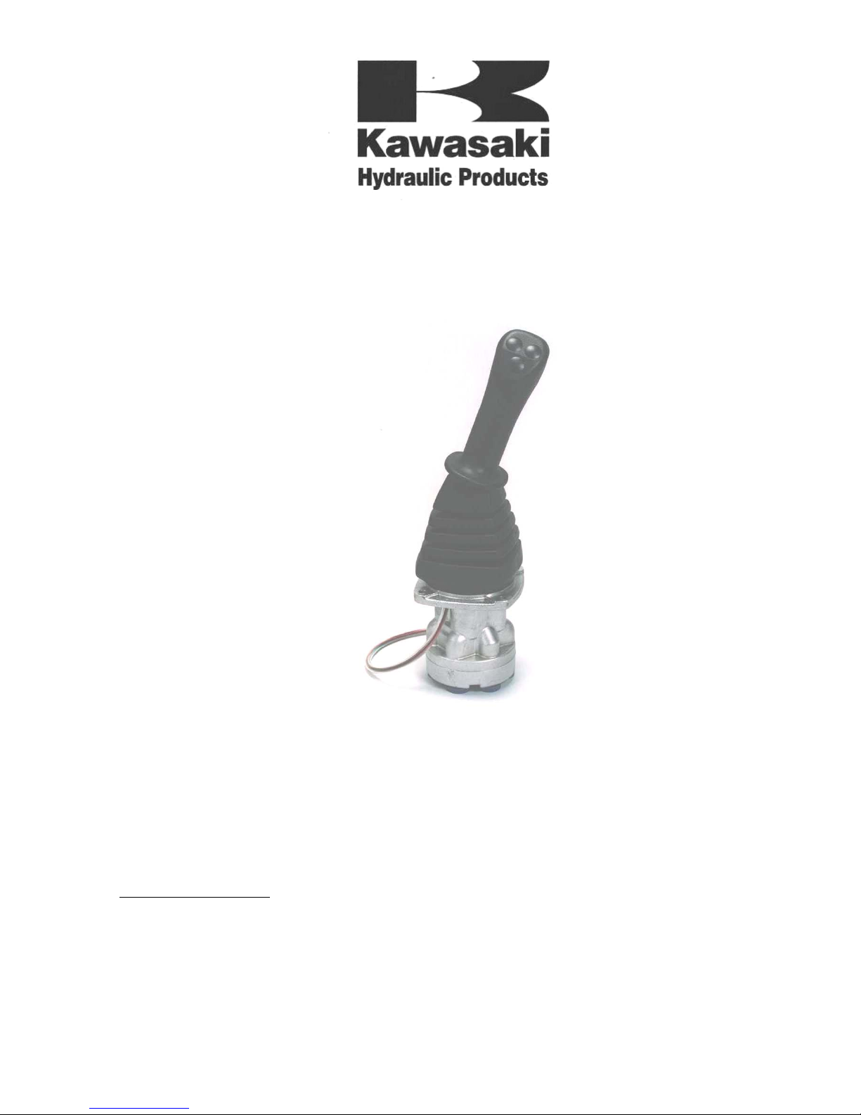
PILOT VALVE
PV48K SERIES
OVERHAUL & MAINTENANCE MANUAL
KAWASAKI PRECISION MACHINERY OF AMERICA
5080 36
Grand Rapids, MI 49512
www.kawasakipmd.com
Date: July 2004
TH
Street S.E.
Copyright © Kawasaki Heavy Industries Ltd.
Page 2

Page 3
Overhaul & Maintenance Manual Pilot Valve PV48K
06/03
Preliminary Page i
COPYRIGHT
Copyright © Kawasaki Heavy Industries Ltd. 2000
All rights reserved. No part of this publication may be reproduced, stored in a retrieval system,
or transmitted in any form or by any means, electronic, mechanical, photocopying, recording or
otherwise, without the prior permission of Kawasaki Heavy Industries Ltd.
Page 4
Pilot Valve PV48K Overhaul & Maintenance Manual
06/03
Preliminary Page ii
Contents
Section Page
Safety .......................................................................................................................iii
1 Description and operation......................................................................................................1
1.1 General ......................................................................................................................1
1.2 Specifications.............................................................................................................1
1.3 Structure ....................................................................................................................2
1.4 Performance...............................................................................................................3
1.4.1 Basic performance.......................................................................................3
1.4.2 Performance of the main parts (see Figure 1) .............................................3
1.5 Operation ...................................................................................................................4
1.5.1 Control Handle Neutral (see Figure 3).........................................................4
1.5.2 Control Handle Tilted (see Figure 4)............................................................5
1.5.3 Control Handle Held (see Figure 5) .............................................................6
1.5.4 Control Handle Tilted Through a Wide Range.............................................7
2 Maintenance..........................................................................................................................7
2.1 Tools Equipment and Torque Settings....................................................................... 7
2.2 Adjustment Standards................................................................................................ 8
2.3 Disassembly............................................................................................................... 9
2.3.1 Preparations.................................................................................................9
2.3.2 Warnings and Cautions................................................................................9
2.3.3 Sequence of disassembly............................................................................9
2.4 Assembly..................................................................................................................17
2.4.1 Preparations...............................................................................................17
2.4.2 Sequence of Assembly ..............................................................................18
3 Troubleshooting, spares & tools..........................................................................................25
3.1 Troubleshooting .......................................................................................................25
3.2 Parts.........................................................................................................................26
3.2.1 Parts List....................................................................................................
27
Illustrations
Figure Page
1. PV48K Valve – Cross Section 2
2. Hydraulic Circuit Plan (Typical) 4
3. Control Handle in Neutral 4
4. Control Handle Tilted 5
5. Control Handle Held 6
6. Push rod Plug & Seals 20
7. Parts Breakdown 25
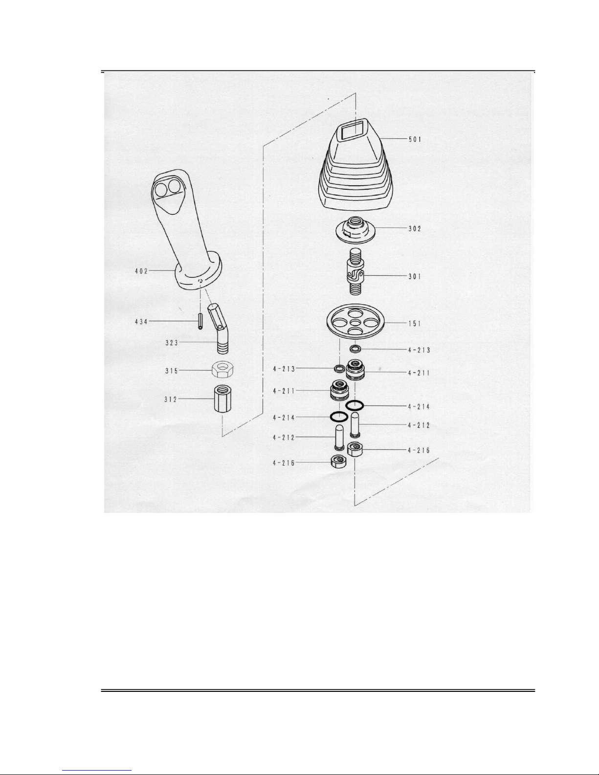
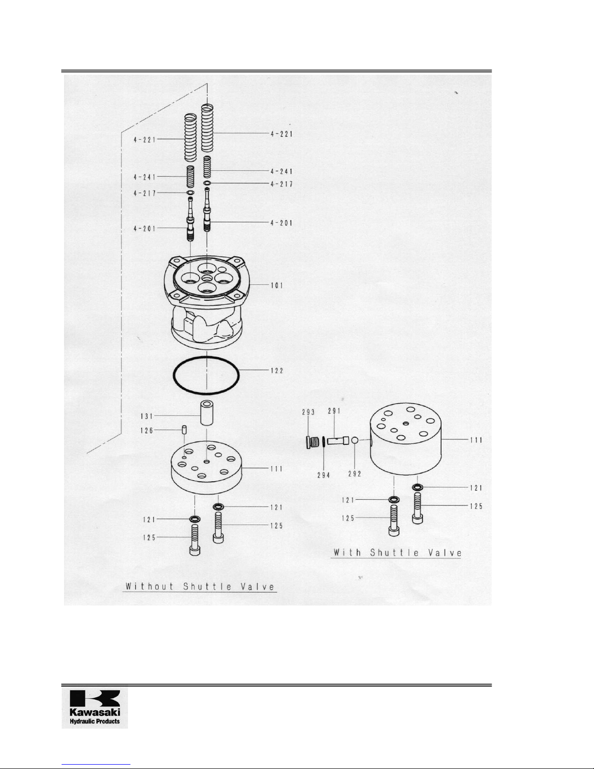
8 Exploded View 29
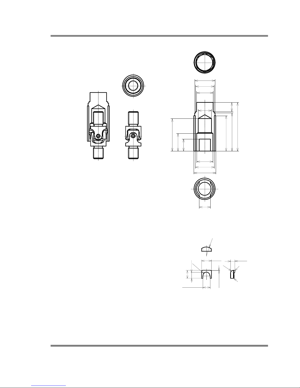
9. Special Jig 31
10. PV48K1THM & PV48KC1THM – Cross Section 32
Page 5
Overhaul & Maintenance Manual Pilot Valve PV48K
06/03
Preliminary Page iii
SAFETY
Liability
Kawasaki Heavy Industries Ltd. guarantee the performance of this valve when supplied new.
Disassembly of the valve will invalidate any remaining warranty. Kawasaki Heavy Industries Ltd
. will not honour any warranty claim resulting from physical impact, mishandling or natural
disaster.
PERSONNEL
Before carrying out any procedures on this valve the safety section of this manual must be read
and understood. Work on the valve, piping and wiring must only be carried out by suitably
qualified personnel.
For safe operation, servicing and checking of this valve, make sure the contents of this manual
are fully understood. Keep this manual available for reference at all times.
These safety notes are intended to ensure that the valve is maintained and operated correctly
and that risks to personnel are minimised.
The instructions in this manual are intended to guide a trained and skilled maintainer to carry
out Overhaul and Maintenance of the valve. The procedures must be combined with current
good Engineering Practices and relevant local safety instructions.
WARNINGS, CAUTIONS AND NOTES
Throughout this manual attention is drawn to specific points as follows:
WARNING!
A WARNING ALERTS THE READER TO POTENTIAL HAZARDS. FAILURE
TO READ AND OBEY THE SAFETY INSTRUCTIONS MAY RESULT IN
SERIOUS INJURY TO PERSONNEL AND DAMAGE TO EQUIPMENT.
CAUTION! A caution alerts the reader to recommendations or instructions, non-
observance of which could cause damage to equipment.
Note: A note provides additional information, which should be given special attention.
Page 6
Pilot Valve PV48K Overhaul & Maintenance Manual
06/03
Preliminary Page iv
OPERATION
During the Operation of the valve Observe the following:
1. Before operating machinery, clear all personnel and obstructions out of the zone of
operation.
2. If the machinery operates dangerously, the pressure source must be isolated
immediately.
3. If anything abnormal (i.e. abnormal noise or oil leaks) occurs, operation should be
stopped immediately and the problem dealt with.
4. Before the valve is run for the first time, confirm that the hydraulic circuits and electrical
wiring are correct and ensure that all fittings and connections are tight.
5. The valve must only be used within the specifications shown in the relevant data sheet.
6. Monitor the temperature of the valve during operation, if the temperature rises suddenly:
(a) Switch off the valve.
(b) Isolate the hydraulic and electrical supplies.
(c) Allow the valve to cool before touching.
(d) Investigate the sudden rise in temperature.
7. Use only the hydraulic oil specified in the relevant data sheet.
8. Make sure that all relevant filters specified in the data sheet are fitted and are in a clean
and operational condition.
HANDLING
Care should be taken with the following when handling the valve:
1. Wear protective clothing when appropriate.
2. Depending on the weight and operating configuration of the main machine, it may be
possible to trap fingers or strain the back.
3. Do not apply weight to, hit, drop or exert external force on the valve.
4. Wipe off any operating oil from the valve and/or floor.
Page 7
Overhaul & Maintenance Manual Pilot Valve PV48K
06/03
Preliminary Page v
REMOV AL AND REPLACEMENT
Precautions for the removal and replacement of the valve:
Removal
Ensure that:
(a) Power to the machine is switched off.
(b) Electric motors, engines etc are at rest.
(c) Pressure inside hydraulic lines is zero.
(d) Residual pressure in the accumulator circuit is released. (i.e. Operate the valve's
lever several (at least ten) times).
Replacement
Ensure that:
(a) Attachment holes and surfaces are kept clean.
(b) The correct bolts are used and tightened to the specified torque values.
(c) Seals are not damaged.
MAINTENANCE AND STORAGE
Precautions for the Maintenance and Storage of the valve:
Maintenance
Ensure that:
(a) No modifications to the product are made by the customer.
(b) Trained personnel carry out maintenance and Overhaul.
Storage
Ensure that:
(a) The ambient temperature and humidity levels are not extreme.
(b) The valve is protected from dust and corrosion.
(c) Provision is made to change the valve seals if the valve is stored for long periods.
Page 8
Pilot Valve PV48K Overhaul & Maintenance Manual
06/03
Preliminary Page vi
Intentionally Blank
Page 9
Overhaul & Maintenance Manual Pilot Valve PV48K
06/03
Page 1
1 DESCRIPTION AND OPERATION
1.1 General
The Pilot PV48K is a remote-control pilot valve with four reduction spools controlling secondary
pressure mounted in a single valve casing. Tilting the control handle controls the output
pressure.
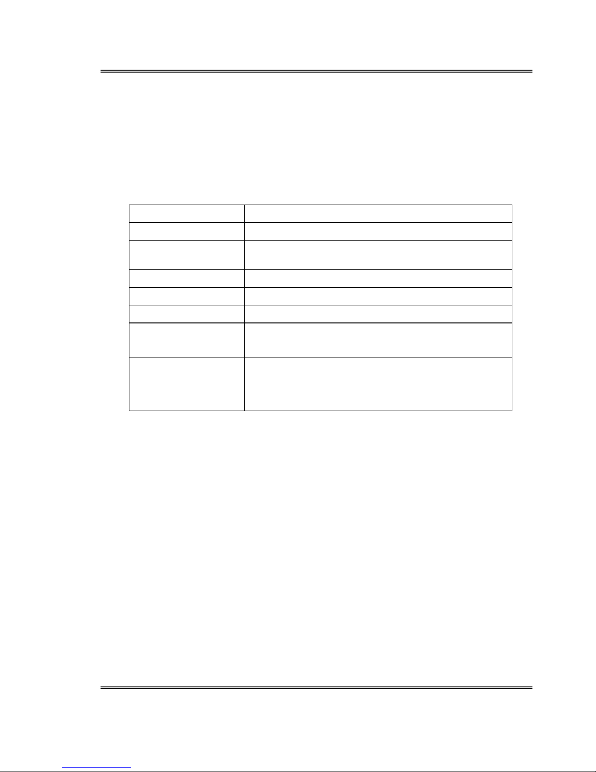
1.2 Specifications
Primary pressure Maximum pressure 6.9Mpa{995psi}
Secondary pressure Maximum control pressure 0~4. 4Mpa{640psi}
Permissible back
pressure
Maximum 0.3Mpa{43psi}
Nominal flow 20L/min{5.3gal/min}
Control angles ±19o, ±25o (single)
Mass 1.9kg
Port size G-1/4(ISO 228/1)
9/16-18UNF(SAE 514)
Piping
A supply pipe approximately φ8mm internal diameter and
a maximum of 3 metres in length should be used to
achieve good responsiveness. The return oil should go
directly to the tank to avoid the effects of back-pressure.
Page 10
Pilot Valve PV48K Overhaul & Maintenance Manual
Issue 1 09/00
Page 2
1.3 Structure
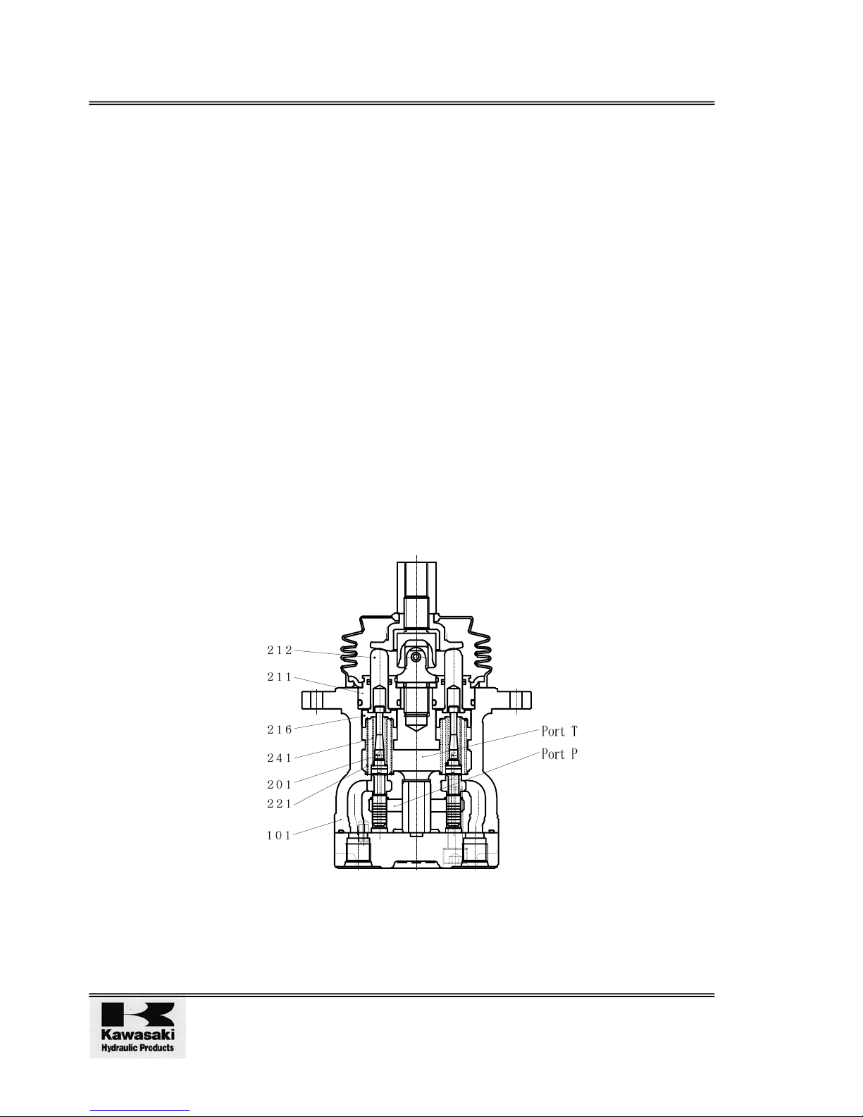
The structure of the pilot valve is as shown in the assembly cross-section (see Figure 1). There
is a vertical axial hole in the casing and the reduction valves are inserted into this.
Each reduction valve comprises:
1. Spool (201)
2. Secondary pressure setting spring (241)
3. Return spring (221)
4. Spring seating (216)
5. Push rod (212)
6. Plug (211)
The secondary pressure setting spring (241) is set such that the secondary pressure is
calculated as 5~10kgf/cm2 (depending on the model). Spool (201) is pushed onto the push rod
(212) by return spring (221).
Tilting the control handle pushes down push rod (212), the spring seat (216) also moves down
and the setting of the secondary pressure setting spring (241) is changed.
Port P, oil inlet (primary pressure) and port T outlet (tank) are in the casing (101).
Por t s 2, 4 Por t s 1, 3
Figure 1 PV48K Valve - Cross-Section
Page 11

Overhaul & Maintenance Manual Pilot Valve PV48K
06/03
Page 3
1.4 Performance
1.4.1 Basic performance
The pilot valve controls the stroke and direction of the control valve spools. This is achieved by
the output pressure of the pilot valve acting on the tip of the control valve spool.
To achieve satisfactory performance, the pilot valve comprises the following elements:
1. An inlet port (P) for oil fed from the hydraulic pump.
2. Multiple output ports (1,2,3 and 4) to allow pressure from the inlet port to act on the
spool tips of the control valve.
3. A tank port (T) to control the output pressure.
4. A spool to connect the output port to the inlet port or tank port.
5. A mechanical assembly, which contains a spring which acts on the spool and controls
the output pressure.
1.4.2 Performance of the main parts (see Figure 1)
The spool (201) operates to take the supply oil pressure from the hydraulic pump. This
switches the oil channel so that the port P oil pressure is directed to the output ports 1,2,3,4 or
to port T. The secondary pressure setting spring (241) determines the output pressure that acts
on the spool (201).
The push-rod (212), which changes the strain of the secondary pressure setting spring (241), is
inserted so that it can move smoothly into the plug (211).
The return spring (221) acts to return the push-rod (212) towards zero displacement without
reference to the output pressure acting on the spring seating (216) and casing (101). This acts
to ensure the return to neutral of the spool (201) and also acts as a resistance spring to provide
the operator with an appropriate operating "feel".
Page 12
Pilot Valve PV48K Overhaul & Maintenance Manual
Issue 1 09/00
Page 4
1.5 Operation
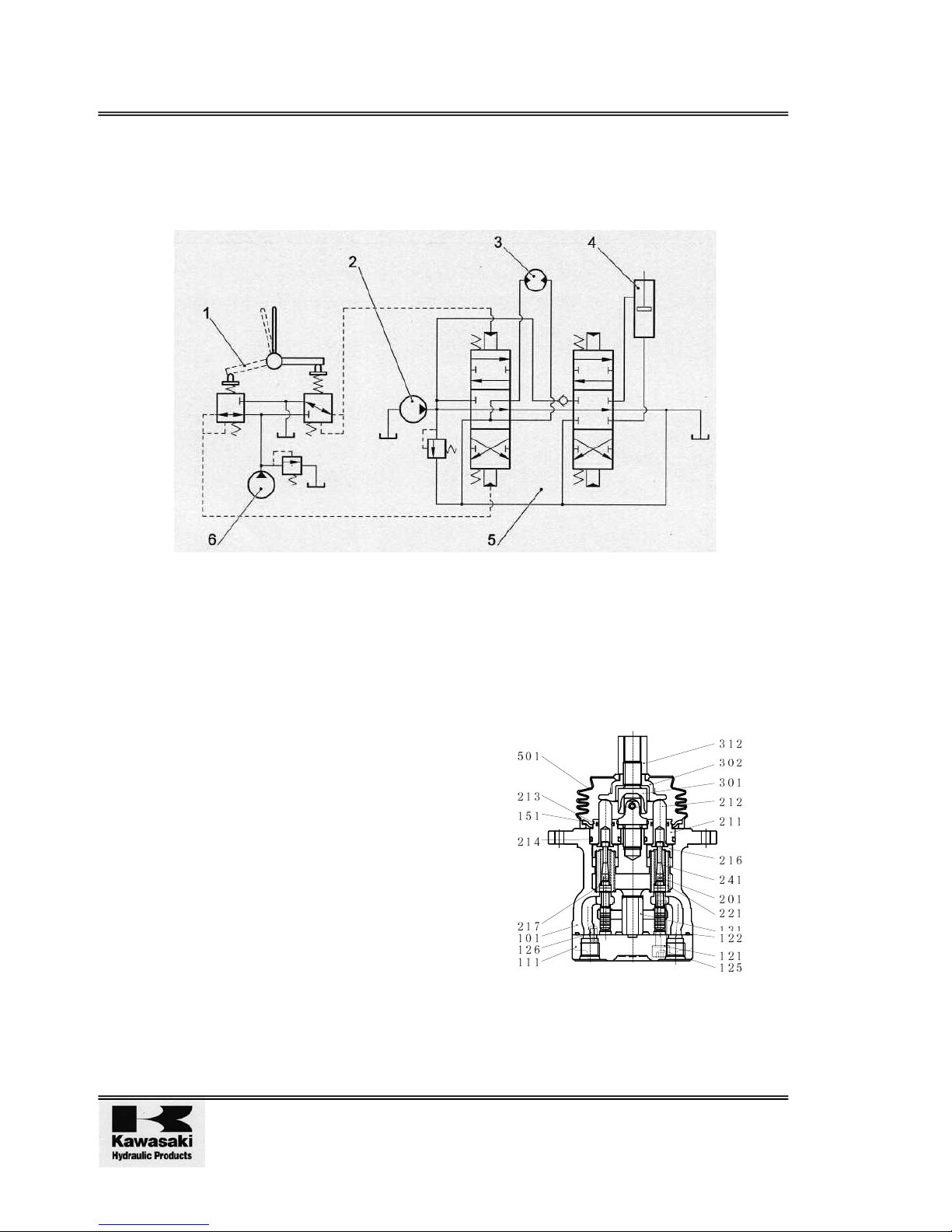
The operation of the pilot valve is described in the hydraulic circuit plan (see Figure 2) and
operation explanatory figures (see Figures 3, 4 and 5). Figure 2 shows a typical example of the
use of the pilot valve.
KEY:
1 Pilot valve 2 Main pump 3 Hydraulic motor
4 Hydraulic cylinder 5 Control valve 6 Pilot pump
Figure 2 Hydraulic Circuit Plan (Typical)
1.5.1 Control Handle Neutral (see Figure 3)
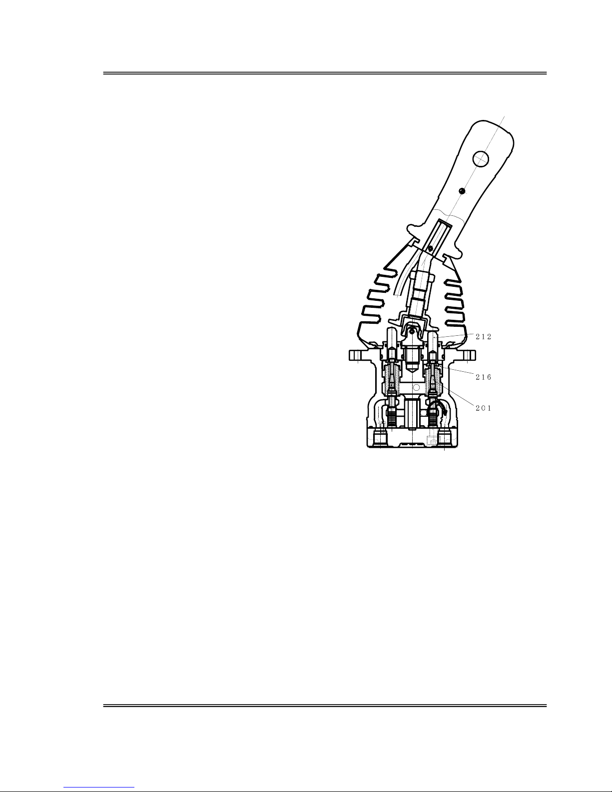
The force of the secondary pressure setting
spring (241) (which determines the output
pressure of the pilot valve) does not act on the
spool (201).
Spool (201) is pressed upward by the return
spring (221)
Spring seating 1 (216) and output ports (2,4)
and port T are open.
The output pressure is the same as the tank
pressure.
Figure 3 Control Handle in Neutral
Page 13
Overhaul & Maintenance Manual Pilot Valve PV48K
06/03
Page 5
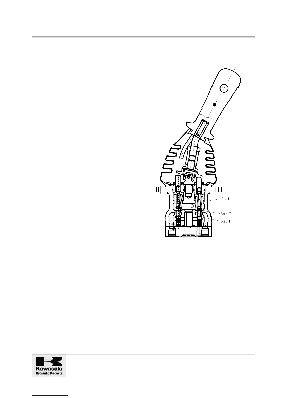
1.5.2 Control Handle Tilted (see Figure 4)
The push-rod moves, (spring seat (216)),
spool (201) moves downward, port P and ports
(2, 4) are open and the oil fed from the pilot
pump flows to ports (2,4) and generates
pressure.
Figure 4 Control Handle Tilted
T
P
Page 14
Pilot Valve PV48K Overhaul & Maintenance Manual
Issue 1 09/00
Page 6
1.5.3 Control Handle Held (see Figure 5)
The pressure of ports (2,4) rises to become
equal to the spring (241) force; the oil pressure
and spring pressures become balanced. If the
pressure of ports (2,4) exceeds the set
pressure. Ports (2,4) and port P close, ports
(2,4) and Port T open and if the pressure of
ports (2,4) falls below the set pressure ports
(2,4) and port P open and ports (2,4) and port
T close. The secondary pressure is kept
constant.
Figure 5 Control Handle Held
P
T
Page 15
Overhaul & Maintenance Manual Pilot Valve PV48K
06/03
Page 7
1.5.4 Control Handle Tilted Through a Wide Range
In some models, when the handle is pressed down beyond a certain angle, the spool top comes
into contact with the inner base of the push rod and the output pressure is continuously
connected to port P.
The spring seating and spring are assembled inside the push rod; when the handle is pressed
down beyond a certain angle, the inner base of the push rod comes into contact with the spring.
The secondary pressure gradient is altered by the force of this spring, before the push-rod base
and the spring seating top come into contact. The output pressure and port P remain
connected.
2 MAINTENANCE
This section details the precautions and procedures required to maintain the valve. The section
does not cover the removal and refitting of the valve to a particular machine.
After assembly of the valve refer to the factory test rig manual and the valve data sheet to test
the valve and check the serviceability of the valve.
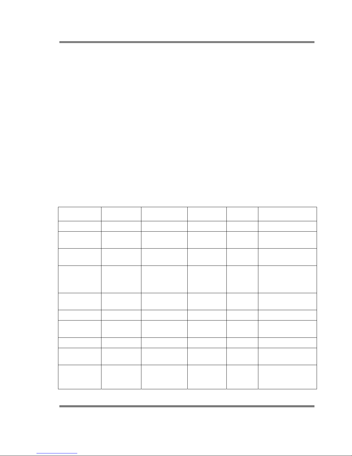
2.1 Tools Equipment and Torque Settings
The following table lists the tools equipment and torque settings that will be required during
disassembly and assembly of the valve.
Tool/
Equipment
Dimensions
(mm)
Part Number Part Name Screw
Size
Tightening Torque
(Nm)
Hex spanner 6 125 Hex bolt M8 20±1.5
Open-Ended
Spanner
22 312 Adjustment
nut
M14 68.6±4.9
Open-Ended
Spanner
32 302 Disc M14 -
Special jig
(page 27,
Figure 8)
24 301 Joint M14 47.1±2.9
Fine Grade
Oilstone
- - - - -
Vice - - - - -
Anti-corrosion
spray
- - - - -
Paraffin - - - - -
Heat-proof
grease
- - - - -
Fine wet/dry
paper #1000,
#2000
- - - - -
Page 16
Pilot Valve PV48K Overhaul & Maintenance Manual
Issue 1 09/00
Page 8
2.2 Adjustment Standards
Items for servicing
and inspection
Standard Notes
Leakage Handle neutral 1000cc/min{0.26gal/
min} maximum
In operation 2000cc/min{0.52gal/
min} maximum
If either of these is reached, the
spool should be changed. If this
does not solve the problem, the
entire pilot valve should be replaced.
Conditions
Primary pressure 2.9Mpa
{427psi} kgf/cm
2
Oil viscosity 23×10-6m2/s
Spool To be replaced when moving parts
are worn down 10µm compared to
non-moving parts.
The same conditions as
above are assumed when
predicting possible leakage
Push-rod To be replaced when the tip is worn
down 10µm or more
Play in control To be replaced when there is 2mm or
more play due to wear of the disc
(302) and joint (301) of the control
Adjustment to be made when
the play is due to e.g.
loosening of parts which
should be tightened.
Operating stability When unusual noise, hunting or
reduction in primary pressure occurs
during operation and it is not
possible to correct this by following
the directions in Paragraph 3
Troubleshooting, the entire pilot
valve should be replaced.
Note: O-rings rings and other sealing materials should preferably be replaced each time the
valve is disassembled but they may be re-used provided a careful check is made that
they are undamaged.
Note: When hexagonal socket (hex) bolts (125) are loosened the seal washers (121) must
be replaced.
Page 17
Overhaul & Maintenance Manual Pilot Valve PV48K
06/03
Page 9
2.3 Disassembly
2.3.1 Preparations
1. Prepare a work bench which is of adequate size to accommodate the parts, tools and
equipment required.
2. Prepare the tools and materials listed in paragraph 2.1.
2.3.2 Warnings and Cautions
WARNING!
SKIN EXPOSURE TO HYDRAULIC FLUIDS, PARAFFIN AND
DEGREASANT CAN BE DAMAGING TO HEALTH. WEAR PROTECTIVE
CLOTHING AND BARRIER CREAMS AS NECESSARY.
CAUTIONS! Care should be exercised when handling all parts.
Parts can be damaged by use of excessive force. Care should be
exercised during maintenance, do not hit or force any part. This may
cause burring or other damage resulting in deterioration in performance.
Parts can be damaged by corrosion caused by humidity and dust. If parts
are to be left in a disassembled condition make sure that all parts are
protected from dust and humidity.
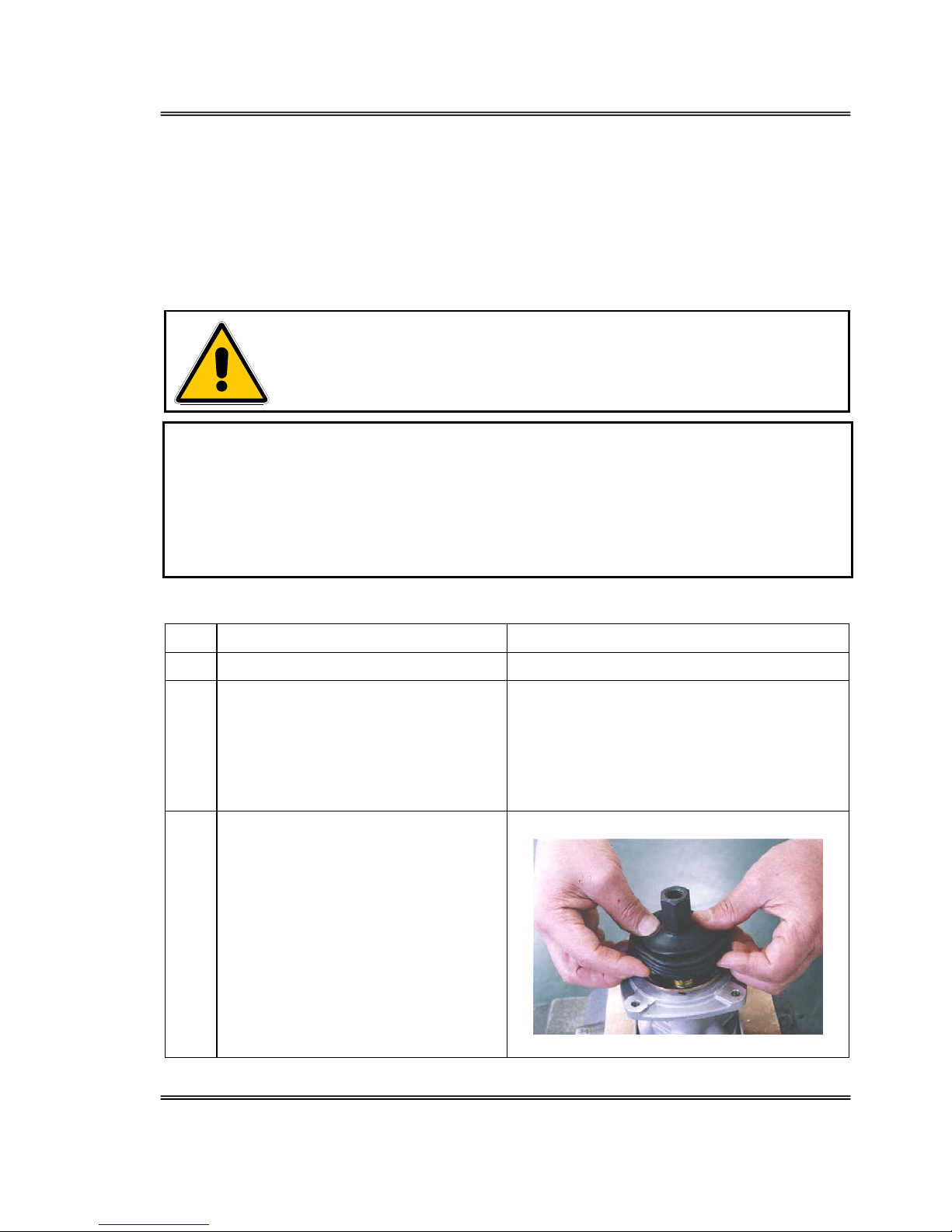
2.3.3 Sequence of disassembly
No. Operation Notes
1. Rinse the pilot valve in paraffin Place blind plug in all ports.
2. Secure the pilot valve in a vice using a
copper or aluminium faced jaws.
Remove the handle assembly from
the valve.[See Figure 10-1 & 10-2
Cross Section]
3. Detach the bellows (501) [See Photo
7-1]
[If outer bellows is attached ,then this
bellows may not be attached.]
Take care not to damage the bellows (501)
Photo 7-1
Page 18
Pilot Valve PV48K Overhaul & Maintenance Manual
Issue 1 09/00
Page 10
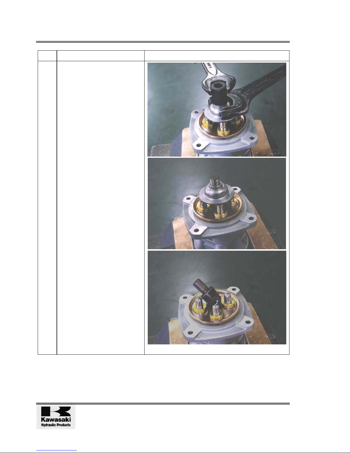
No. Operation Notes
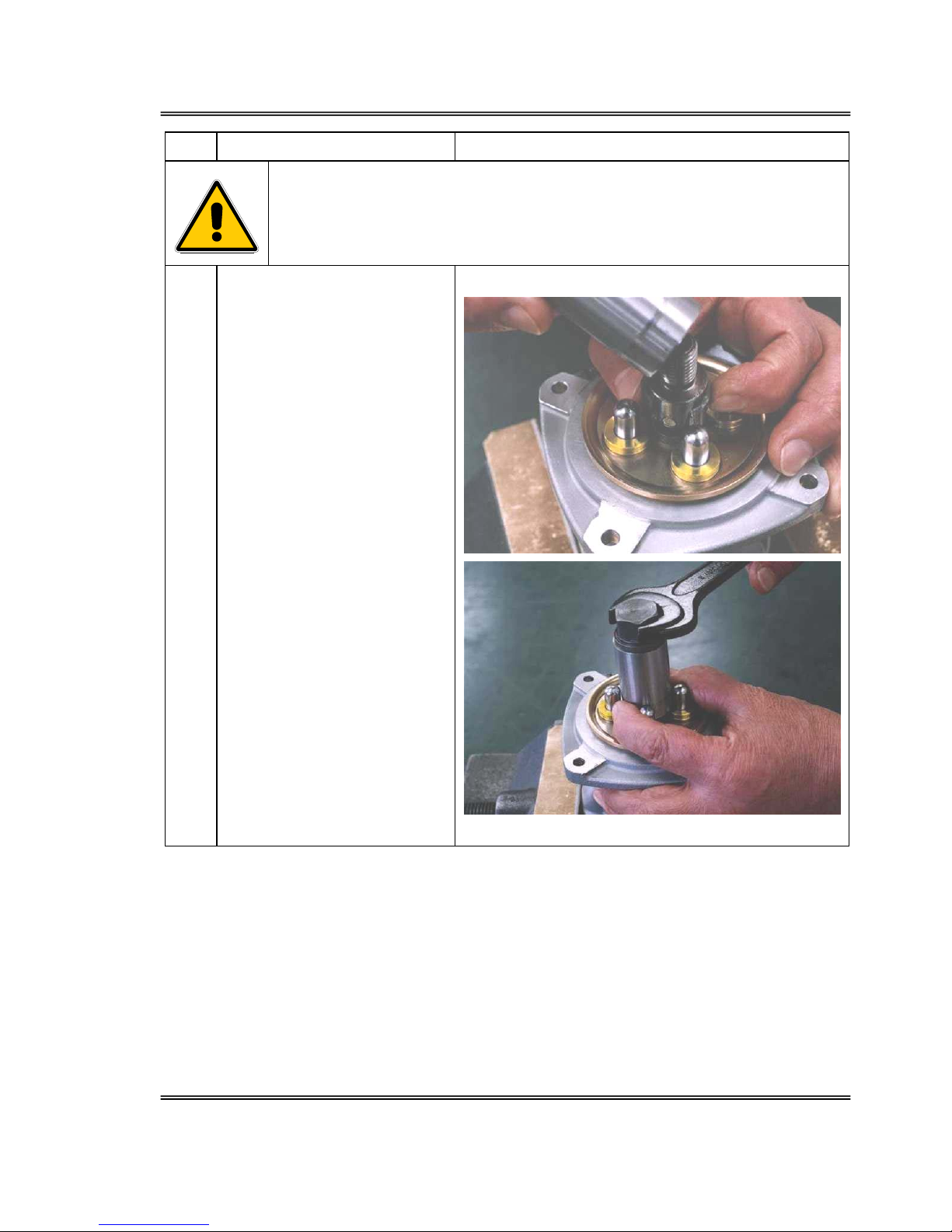
4. Use a spanner applied to both
the adjustment nut (312) and
disc (302) and loosen and then
remove them.
[See Photos 7-2, 7-3, 7-4]
Photos 7-2, 7-3, 7-4
Page 19
Overhaul & Maintenance Manual Pilot Valve PV48K
06/03
Page 11
No. Operation Notes
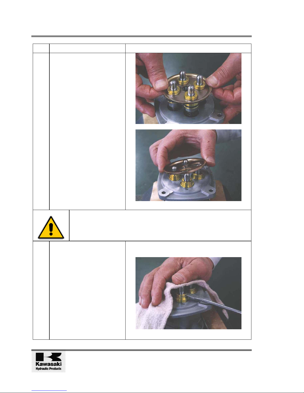
WARNING!
ITEMS UNDER TENSION. THE RETURN SPRING (221), PLATE (151) AND
PUSH-ROD (212) WILL RISE AS JOINT (301) IS LOOSENED. MAKE SURE
THE ITEMS DO NOT FLY OUT AND DAMAGE PERSONNEL IN THE
VICINITY.
5. Using the jig, turn the joint
(301) counter-clockwise to
loosen it
[See Photos 7-5, 7-6]
Photo 7-5 shows the jig attached.
Photos 7-5 & 7-6
Page 20
Pilot Valve PV48K Overhaul & Maintenance Manual
Issue 1 09/00
Page 12
No. Operation Notes
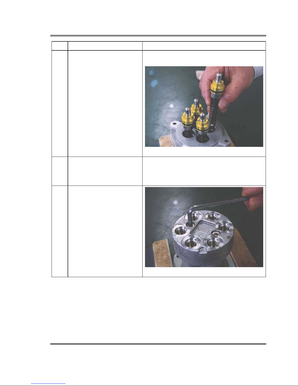
6. Remove the plate (151)
(When the return spring (221)
is strong [See Photo 7-7]
(When the return spring (221)
is weak) [See Photo 7-8]
Photos 7-7 & 7-8
WARNING!
ITEMS UNDER TENSION. THE RETURN SPRING (221) TENSION WILL
BE RELEASED WHEN PLUG (211) IS REMOVED. MAKE SURE THE ITEM
DOES NOT FLY OUT AND DAMAGE PERSONNEL IN THE VICINITY.
7. When the return spring (221) is
weak, the plug (211) is held in
the casing (101) by the friction
of the O-ring. Remove this
using a screwdriver.
[See Photo 7-9]
Use the groove around the plug and take care to
apply force evenly to avoid damage
Photo 7-9
Page 21
Overhaul & Maintenance Manual Pilot Valve PV48K
06/03
Page 13
No. Operation Notes
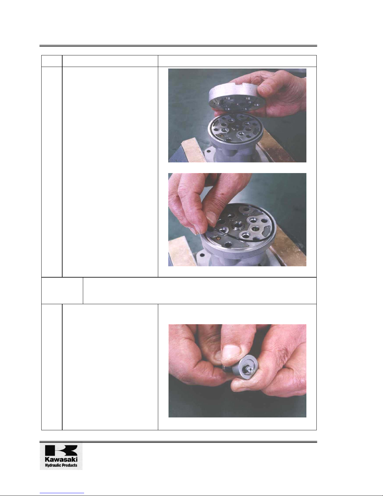
8. Remove the push-rod (212),
plug (211), reduction valve
assembly and return spring
(221) from the casing (101).
[See Photo 7-10]
Note the location in relationship with the casing
aperture.
Photo 7-10
9. Secure the pilot valve in the
vice so that the port plate (111)
is at the top.
10. Loosen the hex bolt (125) with
the Allen wrench.
[See Photo 7-11]
Photo 7-11
Page 22
Pilot Valve PV48K Overhaul & Maintenance Manual
Issue 1 09/00
Page 14
No. Operation Notes
11. Remove the port plate (111)
and O-ring (122) from the
casing (101).
[See Photos 7-12 & 7-13]
Extract the bush (131) from the
casing (101).
Photos 7-12 & 7-13
CAUTION! The surface of the spool (201) and the spring (216) can be damaged by
mis-handling. Take care not to damage the surface of the spool during
removal and do not push the spring seating down more than 6mm.
12. The reduction valve is
disassembled by pressing
down the spring seating (216)
and flexing the secondary
pressure spring (241), sliding
the spring seating (216)
sideways and removing it from
the spool (201) via the larger
aperture. [See Photo 7-14]
Take care not to damage the surface of the spool
(201).
Photo 7-14
Page 23
Overhaul & Maintenance Manual Pilot Valve PV48K
06/03
Page 15
No. Operation Notes
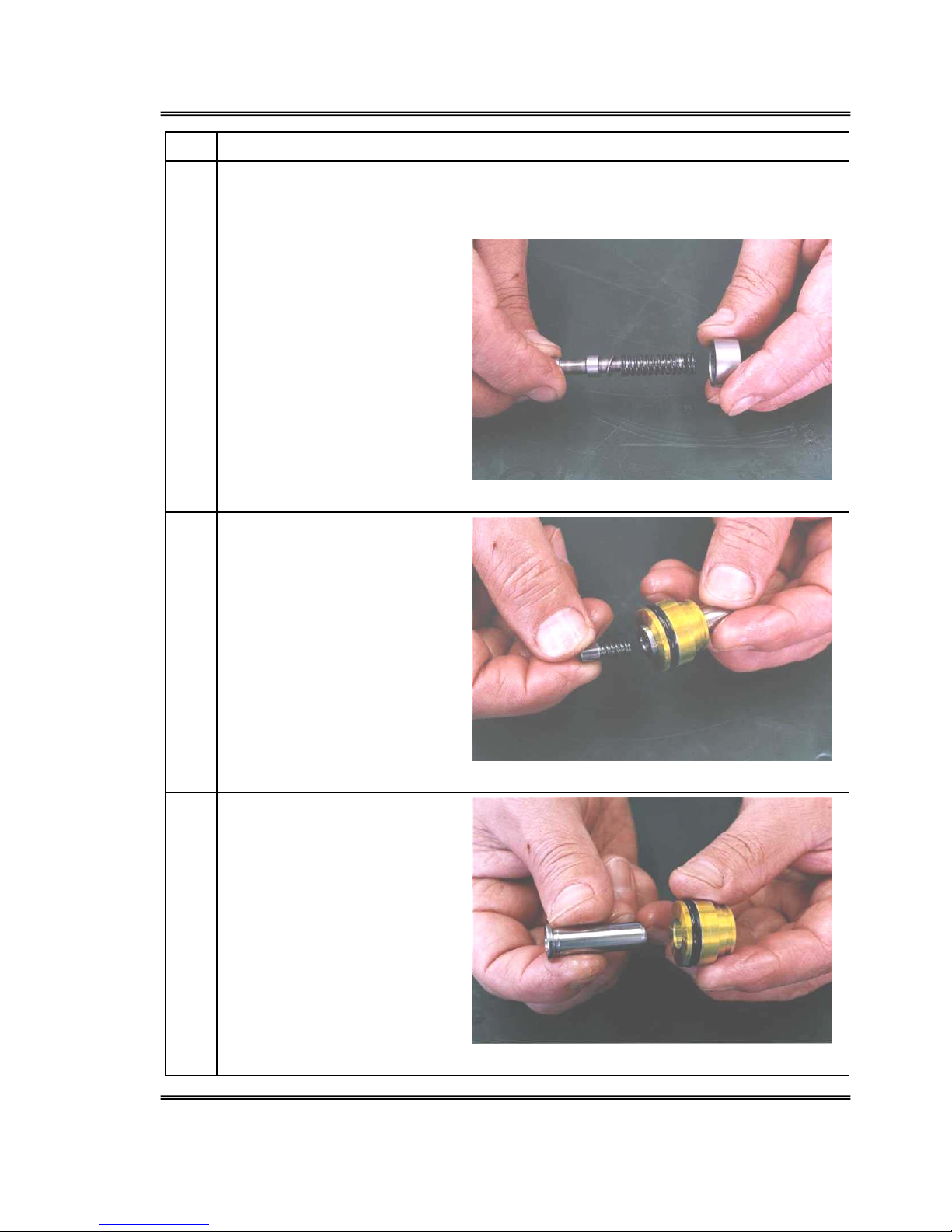
13. Take the spool (201), spring
seating (216), secondary
pressure spring (241) and
washer #2 (217) apart
[See Photo 7-15]
Take care not to damage the surface of the spool
(201).
Keep these parts together until reassembly.
Photo 7-15
14. Remove the secondary spring
(246) and spring seating (218)
from the push-rod (212).
[See Photo 7-16]
Photo 7-16
15. Extract the push-rod (212)
from the plug (211).
[See Photo 7-17]
Photo 7-17
Page 24
Pilot Valve PV48K Overhaul & Maintenance Manual
Issue 1 09/00
Page 16
No. Operation Notes
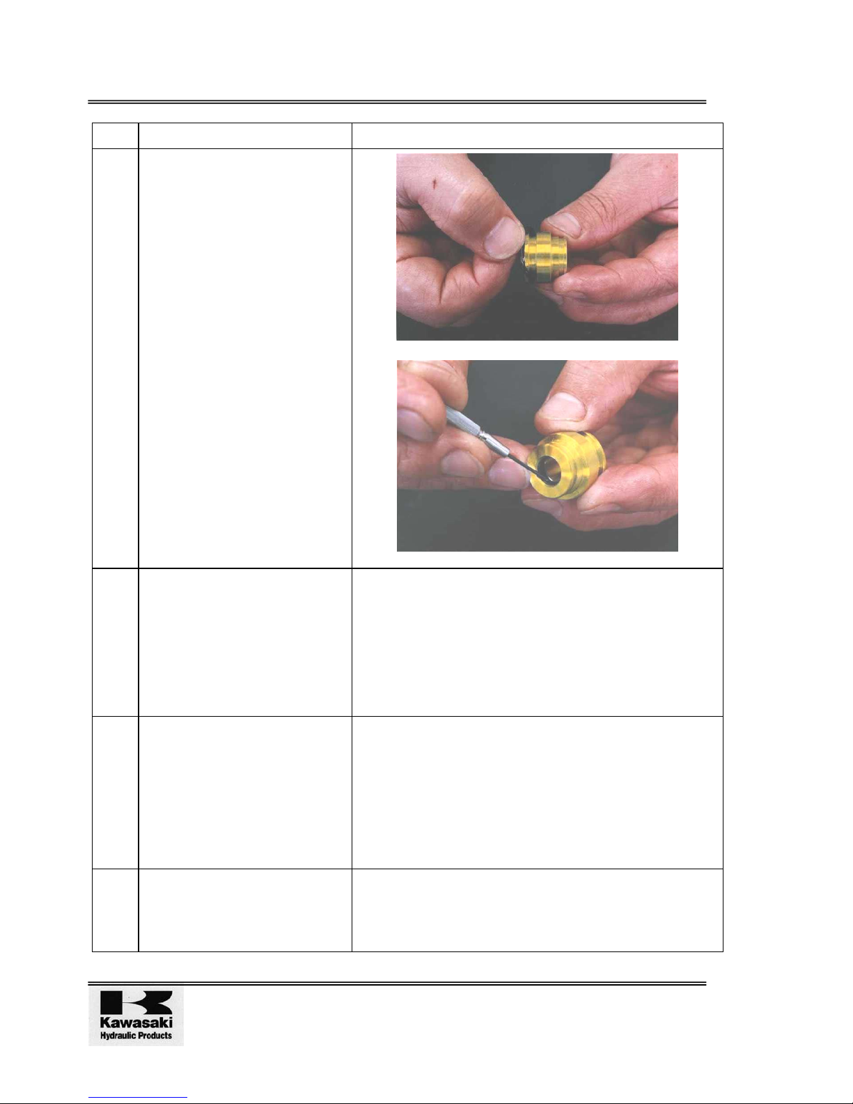
16. Detach the O-ring (214) and
seal (213) from the plug (211).
Detach the seal (213) using a
small screwdriver.
[See Photos 7-18 & 7-19]
Photos 7-18 & 7-19
17. Cleaning of parts:
1. Wash the parts by placing
in an initial bath containing
paraffin (or similar cleaning
fluid).
To reduce the risk of damage if dirty parts are initially
washed in oil. To remove the dirt and oil. Soak
thoroughly so that dirt and oil float to the surface.
Dirty paraffin could result in damage to the parts, and
deterioration in performance after reassembly. Ensure
the contamination of the paraffin is thoroughly
monitored and controlled.
2. Place the parts in a finish
wash container, rotate this
slowly until even the inner
areas of the parts are
clean.
(Finish wash)
Wipe of the paraffin on the
parts using clean cloth.
If compressed air is used for drying, dust and moisture
in the compressed air may damage the parts and make
corrosion more likely.
18. Prevention of corrosion of
parts
Coat the parts with the anti-
corrosion preparation.
If the parts are left to stand for some time after
cleaning, they may start to corrode and the
performance after reassembly will be impaired.
Page 25

Overhaul & Maintenance Manual Pilot Valve PV48K
06/03
Page 17
2.4 Assembly
2.4.1 Preparations
1. Prepare a work bench which is of adequate size to accommodate the parts, tools and
equipment required.
2. Prepare the tools and materials listed in paragraph 2.1.
3. When assembling make sure that all metal particles and foreign bodies are removed
from the parts and all burr and impact marks are removed using the oilstone.
4. All O-rings and backup rings are to be replaced.
5. Take care not to damage the O-rings and backup rings when fitting them (Apply a small
quantity of grease to allow them to be fitted smoothly).
6. When fitting the parts, some grease may be applied to keep them in place.
7. Bolts etc are to be tightened to the torque values shown in Paragraph 2-1. Measure the
torque using a torque wrench.
8. When Assembly is complete, block all ports with blind plugs to keep out dust and
moisture.
Page 26
Pilot Valve PV48K Overhaul & Maintenance Manual
Issue 1 09/00
Page 18
2.4.2 Sequence of Assembly
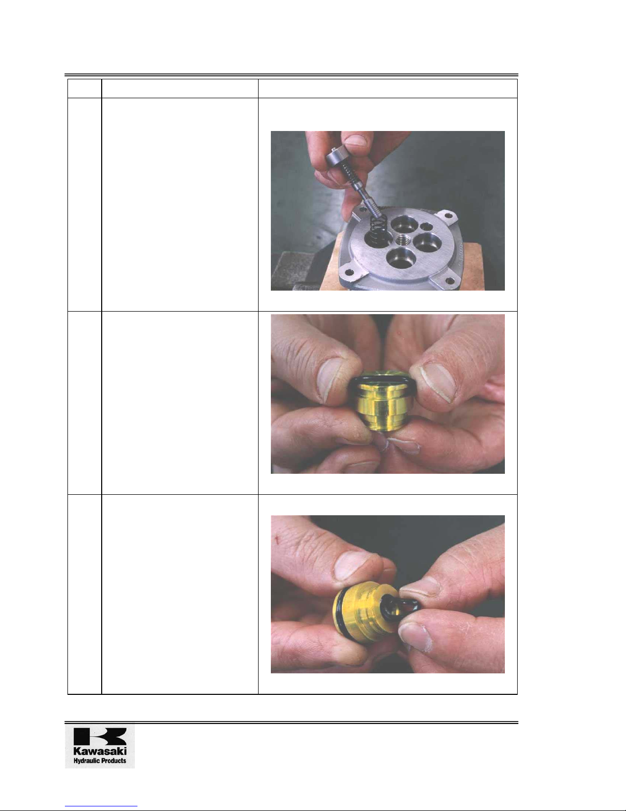
No. Operation Notes
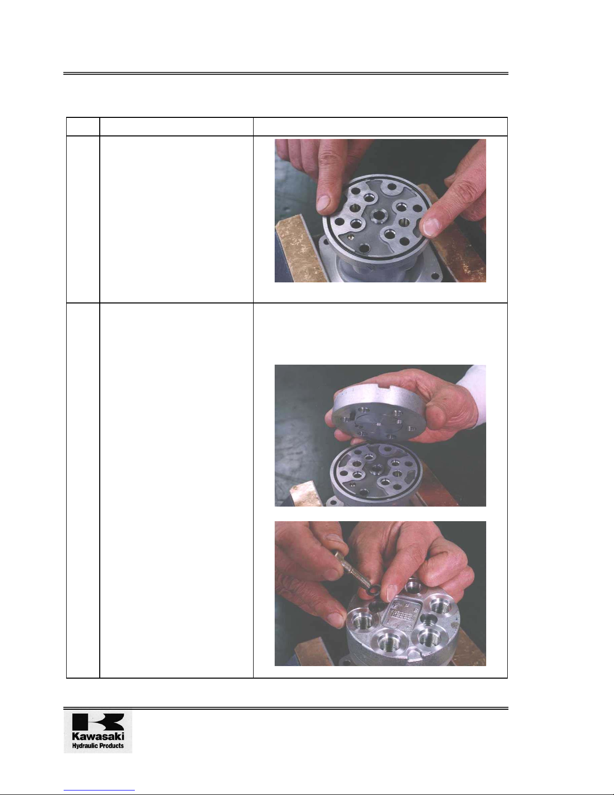
1. Fit the bush (131) and O-ring
(122) into the casing (101).
[See Photo 7-20]
Photo 7-20
2. Attach the port plate (111) to
the casing (101) using hex
bolts (125) and seal washers
(121)
[See Photos 7-21 & 7-22]
Note the fitting position so that the spring pin (126)
can be inserted into the casing aperture.
The sealing washers should be replaced with new
washers.
Photos 7-21 & 7-22
Page 27
Overhaul & Maintenance Manual Pilot Valve PV48K
06/03
Page 19
No. Operation Notes
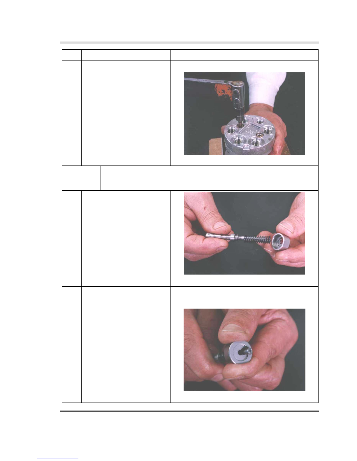
3. Tighten the hex bolts (125) to
the specified torque
[See Photo 7-23]
Slowly tighten the bolt alternately.
Photo 7-23
CAUTION! The surface of the spool (201) and the spring (216) can be damaged by
mis-handling. Take care not to damage the surface of the spool during
assembly and do not push the spring seating down more that 6mm.
4. Insert, in this order, the washer
#2 (217), secondary spring
(241) and spring seating (216)
onto the spool (201).
[See Photo 7-24]
Photo 7-24
5. Press down the spring seating
(216) to flex the secondary
pressure spring (241) while
sliding the spring sideways
through the larger aperture to
attach it to the spool (201).
[See Photo 7-25]
Fit the return spring (221) into
the casing (101).
Do not press the spring seating down more than
6mm
Photo 7-25
Page 28
Pilot Valve PV48K Overhaul & Maintenance Manual
Issue 1 09/00
Page 20
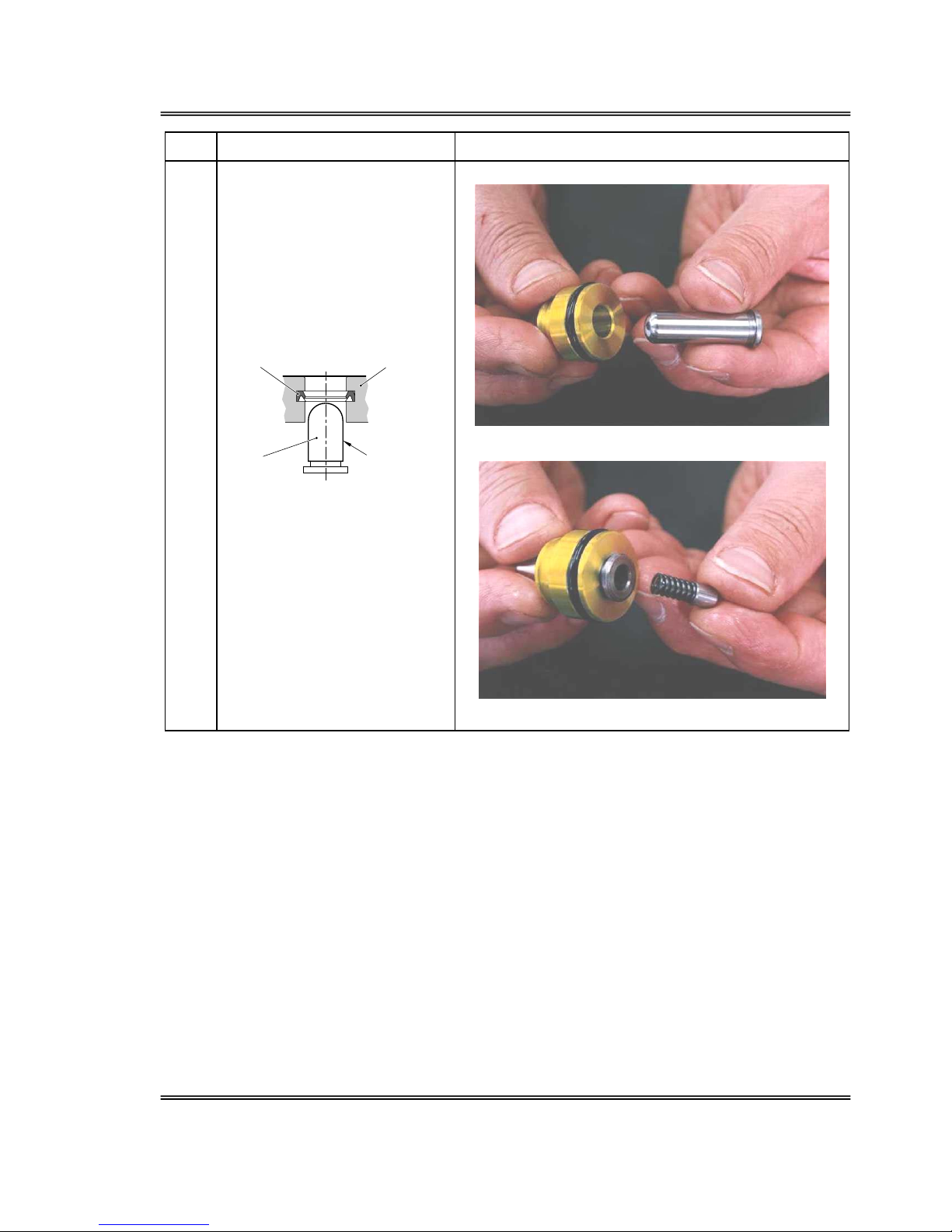
No. Operation Notes
6. Fit the reduction valve
assembly into the casing (101)
[See Photo 7-26]
Fit in the locations noted in step 8 of the disassembly
procedure.
Photo 7-26
7. Fit the O-ring (214) into the
plug (221).
[See Photo 7-27]
Photo 7-27
8. Fit the seal (213) into the plug
(211).
[See Photo 7-28]
Fit the lip of the seal (213) as shown below.
Photo 7-28
Page 29
Overhaul & Maintenance Manual Pilot Valve PV48K
06/03
Page 21
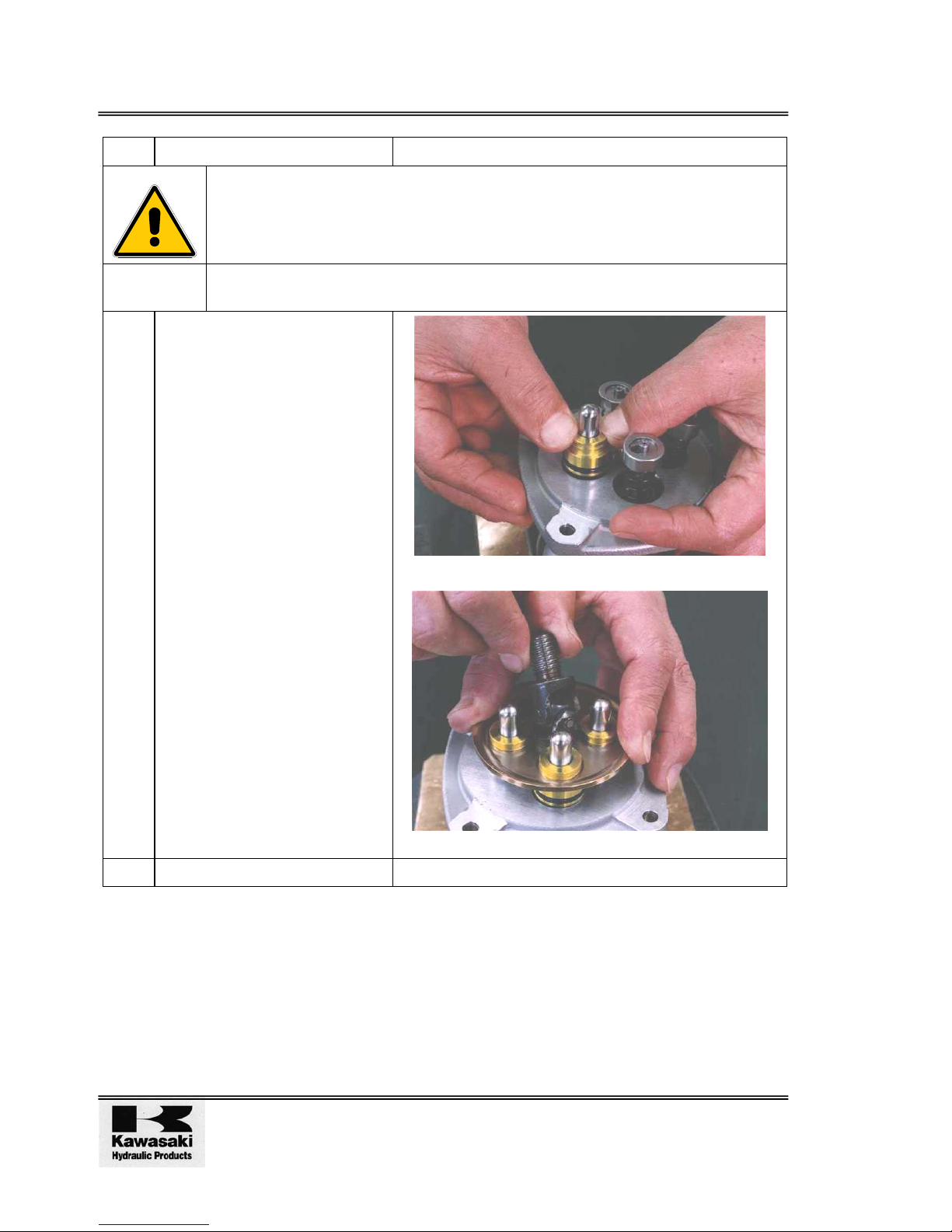
No. Operation Notes
9. Fit the push-rod (212) into the
plug (211)
[See Photo 7-29 and Figure 6]
Fit the secondary spring (246)
and spring seating (218) into
the push-rod (212).
[See Photo 7-30]
Plug
Coated with
Hydraulic Oil
Push
Rod
Seal
Figure 6 Push rod Plug &
Seals
Apply hydraulic oil to the surface of the push-rod.
Photos 7-29 & 7-30
Page 30
Pilot Valve PV48K Overhaul & Maintenance Manual
Issue 1 09/00
Page 22
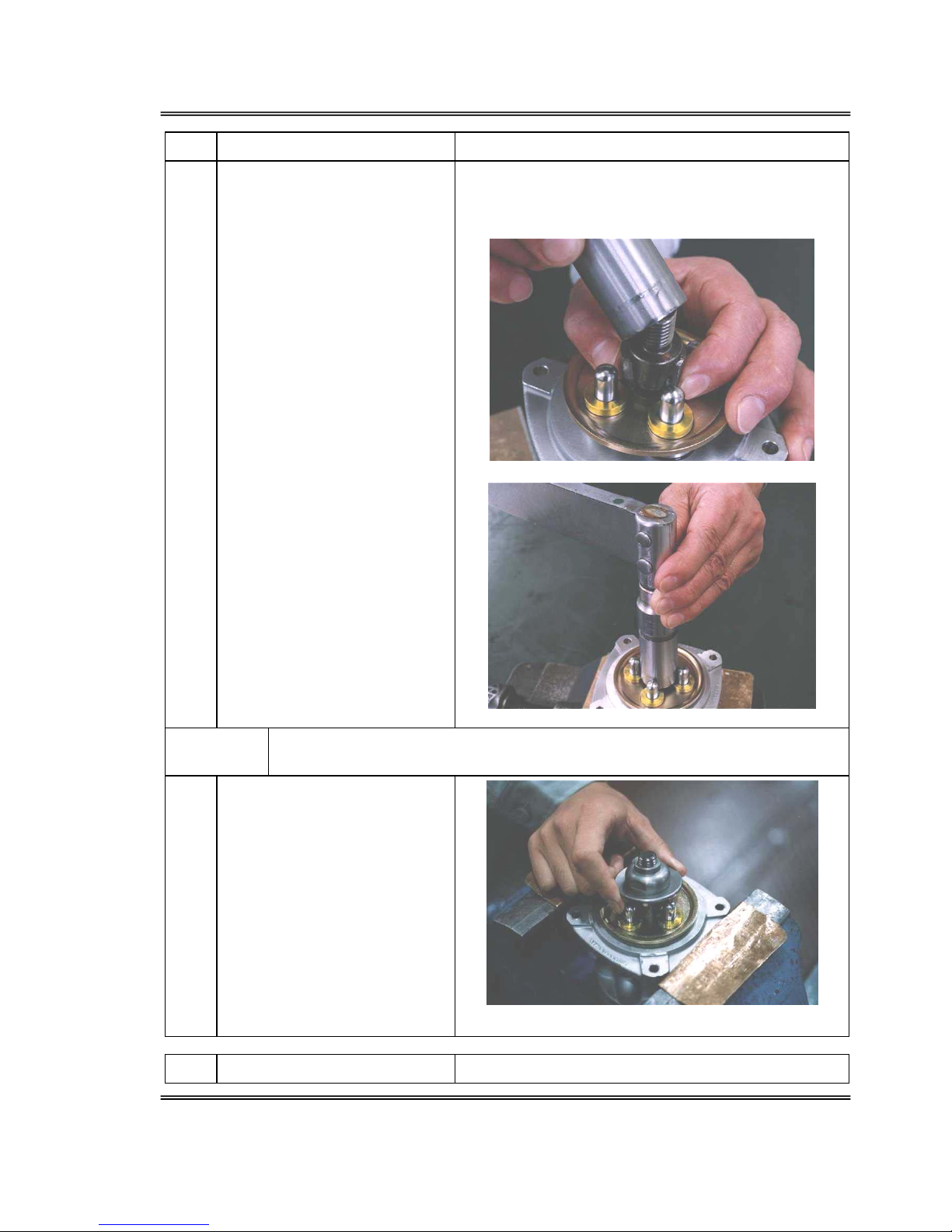
No. Operation Notes
WARNING!
ITEMS UNDER TENSION. THE PLUG ASSEMBLY AND PLATE (151) HAVE
TO BE ASSEMBLED AGAINST SPRING TENSION. MAKE SURE THE ITEM
DOES NOT FLY OUT AND DAMAGE PERSONNEL IN THE VICINITY.
CAUTION! The surface of the spool (201) and aperture (101) can be damaged by mis-
handling. Take care not to damage the surface of either during assembly.
10. Fit the plug assembly into the
casing (101). When the return
spring (221) is weak, it is held
in place by the friction of the
O-ring (214)[
(See Photo 7-31]
When the return spring (221) is
strong, use the plate (151) to
insert all four simultaneously
and temporarily secure them
with the joint (301).
[See Photo 7-32)
Photos 7-31 & 7-32
11. Attach the plate (151).
Page 31
Overhaul & Maintenance Manual Pilot Valve PV48K
06/03
Page 23
No. Operation Notes
12. Tighten the joint (301) to the
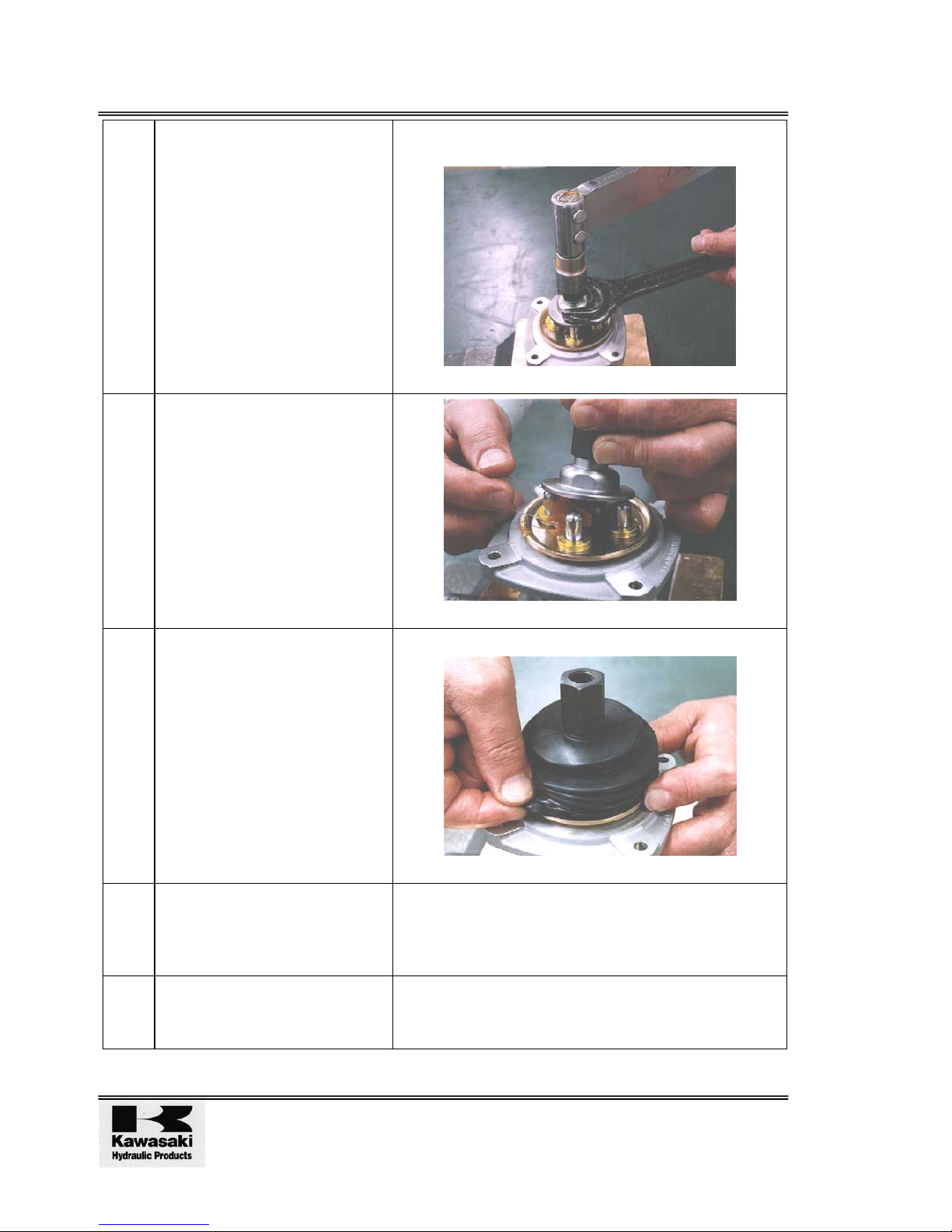
casing (101) to the specified
torque using the special jig.
[See Photos 7-33 & 7-34]
Photo 7-33 shows the jig attached.
Screw down to a position where the four push-rods
(212) are in contact equally.
Photos 7-33 & 7-34
CAUTION! Excessive tightening or wrong positioning of the disc can cause the
valve to malfunction..
13. Attach the disc (302) onto the
joint (301)
[See Photo 7-35]
Photo 7-35
No. Operation Notes
Page 32
Pilot Valve PV48K Overhaul & Maintenance Manual
Issue 1 09/00
Page 24
14. Install the adjustment nut
(312), tighten up the discs
(302) with a spanner on both
and tighten the adjustment nut
to the specified torque
[See Photo 7-36]
Do not allow the position of the disc (302) to shift
during tightening.
Photo 7-36
15. Apply grease to the rotating
part of the joint (301) and end
of the push-rod (212).
[See Photo 7-37]
Photo 7-37
16. Attach the bellows (501).
[ If outer bellows is attached,
then this bellows may not be
attached ].
[See Photo 7-38]
Take care not to tear the bellows.
Photo 7-38
17. Fit the handle assembly into
the valve.
[See Figure 10-1 & 10-2 Cross
Section]
18 Spray anti-corrosion
preparation into each port and
insert blind plugs.
Page 33
Overhaul & Maintenance Manual Pilot Valve PV48K
06/03
Page 25
3 TROUBLESHOOTING, SPARES & TOOLS
3.1 Troubleshooting
The table below shows the faults, the possible causes and the possible solutions. However,
problems with a machine are often not caused by one part but by its relationship with other
parts. It should be noted that it may be necessary to deal with problems other than those listed
below.
The table below does not list all possible causes and solutions. It may be necessary for the
repair technician to investigate other solutions.
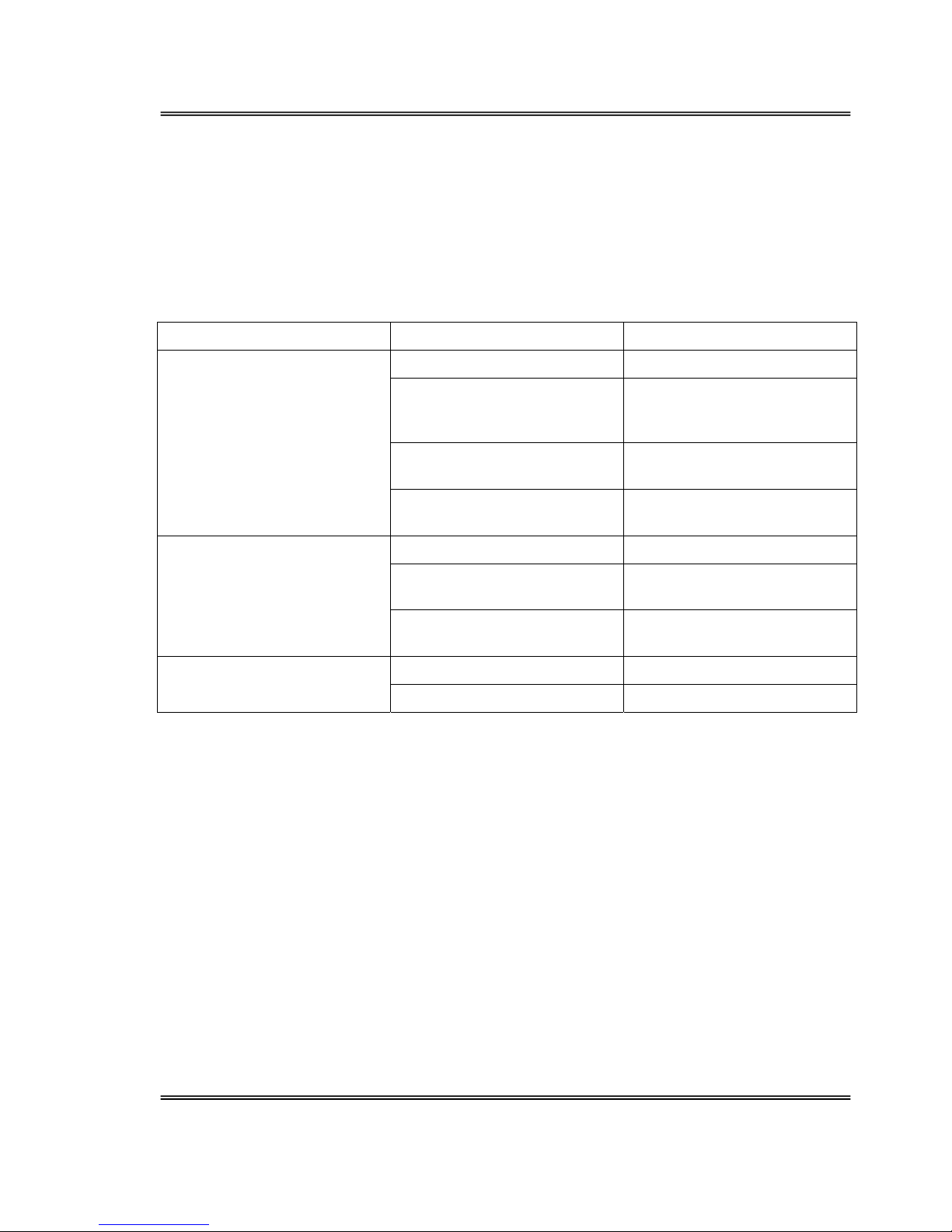
Fault Cause Solution
Inadequate primary pressure Ensure primary pressure
Bending or displacement of
the secondary pressure spring
(241)
Replace with new part
Abnormally large gap between
spool (201) and casing (101)
Replace spool (201)
Secondary pressure does not
rise
Play in control handle Disassemble/re-assemble and
replace control handle.
Sliding parts are catching Fix catching parts.
Variations in tank line
pressure
Return directly to oil tank
Secondary pressure is
unstable
Air in pipe Operate several times to
remove air
High tank line pressure Return directly to oil tank Secondary pressure is high
Sliding parts are catching Fix catching parts
Page 34
Pilot Valve PV48K Overhaul & Maintenance Manual
Issue 1 09/00
Page 26
3.2 Parts
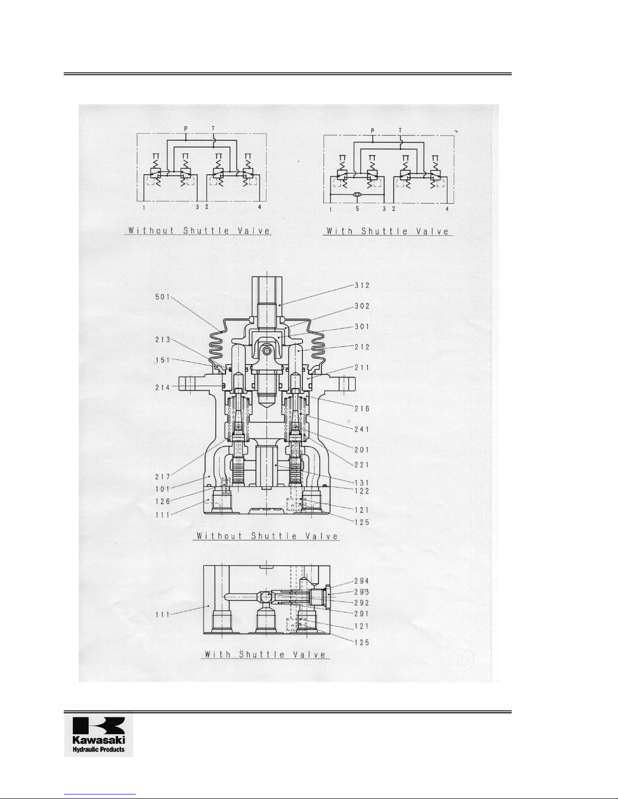
Figure 7 Parts Breakdown
Page 35
Overhaul & Maintenance Manual Pilot Valve PV48K
06/03
Page 27
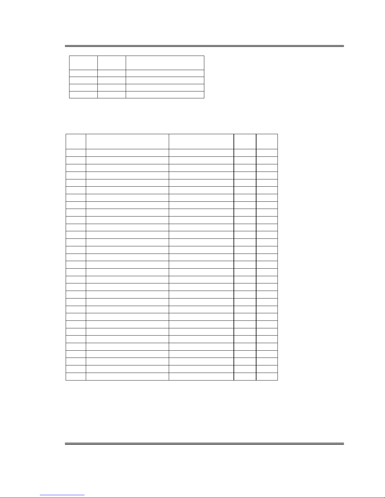
No Screw
Size
Tightening Torque
125 M8 20.6±1.5 Nm
301 M14 47.1±2.9 Nm
312 M14 68.6±4.9 Nm
315 M14 49.0±3.5 Nm
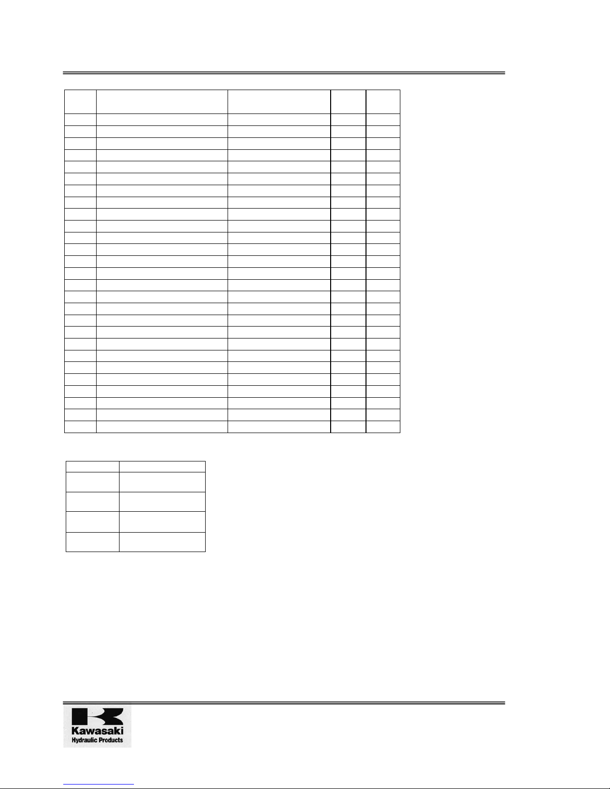
3.2.1 Part List
Pilot valve PV48KC1206
No. Part name Part number Q'ty/
unit
Class
101 Casing P- VZ331701046 1 /
111 Port plate P- VZ333600437 1 C
121 Seal washer P- 5DT01X01121 2 C
122 O-ring P- VZ3319000211 1 C
125 Socket screw P- 0SBM865 2 D
126 Pin; spring P- 0SPV510 1 D
131 Bush P- VZ333400157 1 C
151 Plate P- VZ333600316 1 C
201 Spool P- VZ033201847 4 /
211 Plug P- 5DT01X00211 4 C
212 Push rod P- 5DT01X06212 4 C
213 Seal P- 5DT61X20213 4 C
214 O-ring P- 00RBP20 4 D
216 Seat; spring P- VZ032700191 4 C
217 Washer P- 5DT01X00217 4 C
221 Spring P- VZ033401234 4 C
241 Spring P- VZ033401803 4 C
291 Seat P- VZ3318001341 1 C
292 Ball P- 0DW516 1 C
293 Plug P- 0R0MH12 1 C
294 O-ring P- 00RBP10 1 D
301 Joint P- 5DT61X01301 1 C
302 Circular plate P- VZ333600280 1 C
312 Adjusting nut P- 5DT61X00311 1 C
315 Nut P- 5DT61X00315 1 C
323 Lever P- VZ334100046 1 C
402 Knob P- VZ333100101A 1 C
434 Pin; spring P- VZ035400224 1 C
457 Bush P- VZ3334002152 1 C
501 Boot P- VZ332100026 1 C
Ass'y seal kit P- VZ033850106 1 A
Page 36
Pilot Valve PV48K Overhaul & Maintenance Manual
Issue 1 09/00
Page 28
PV48K1207
No. Part name Part number Q'ty/
unit
Class
101 Casing P- VZ331701046 1 /
111 Port plate P- VZ333600499 1 C
121 Seal washer P- 5DT01X01121 2 C
122 O-ring P- VZ3319000211 1 C
125 Socket screw P- VZ0362001841 2 C
126 Pin; spring P- 0SPV510 1 D
131 Bush P- VZ333400157 1 C
151 Plate P- VZ333600316 1 C
201 Spool P- VZ033201847 4 /
211 Plug P- 5DT01X00211 4 C
212 Push rod P- 5DT01X06212 4 C
213 Seal P- 5DT61X20213 4 C
214 O-ring P- 00RBP20 4 D
216 Seat; spring P- VZ032700191 4 C
217 Washer P- 5DT01X00217 4 C
221 Spring P- VZ033401234 4 C
241 Spring P- VZ033401803 4 C
301 Joint P- 5DT61X01301 1 C
302 Circular plate P- VZ333600280 1 C
312 Adjusting nut P- 5DT61X00311 1 C
315 Nut P- 5DT61X00315 1 C
323 Lever P- VZ334100046 1 C
402 Knob P- VZ333100101A 1 C
434 Pin; spring P- VZ035400224 1 C
457 Bush P- VZ3334002152 1 C
501 Boot P- VZ332100026 1 C
Ass'y seal kit P- VZ033850066 1 A
Class Code Meaning
A Parts supplied sub-
assembled
C Parts individually
supplied
/ Parts not supplied
D Standardised parts
commonly available
Page 37
Overhaul & Maintenance Manual Pilot Valve PV48K
06/03
Page 29
Figure 8-1 PV48K Exploded View
Page 38
Pilot Valve PV48K Overhaul & Maintenance Manual
Issue 1 09/00
Page 30
Figure 8-2 PV48K Exploded View
Page 39
Overhaul & Maintenance Manual Pilot Valve PV48K
06/03
Page 31
Note:
2x inserts (as show right) are required as UJ
inserts (These inserts are required to support
the UJ vertically. Refer to Page 10 Para. 5
Photos 7-5)
φ 29
φ 26. 5
23. 5
φ 19
17
25
46
φ 23
φ 27
φ 31
16
13
50
54
69
12. 5
9. 5
11. 6± 0. 1
R
5
.
8
15.5±0.1
R
1
3
0. 5× 15°
C
0
.
5
C
0
.
5
6. 5± 0. 1
R
4
.
5
Figure 9 Special Jig
Page 40
Pilot Valve PV48K Overhaul & Maintenance Manual
Issue 1 09/00
Page 32
Intentionally Blank
Figure 10-1
Page 41

Overhaul & Maintenance Manual Pilot Valve PV48K
06/03
Page 33
Intentionally Blank
Figure 10-2
Page 42
KAWASAKI HEAVY INDUSTRIES, LTD.
PRECISION MACHINERY DIVISI0N
Tokyo Head Office World Trade Center Bldg.,4-1 Hamamatsu-cho
2-chome,Minato-ku,Tokyo 105-6116,Japan
Tel: 81-3-3435-6862
Fax: 81-3-3435-2023
Nishi-Kobe Works 234 Matsumoto,Hazetani-cho,Nishi-ku,Kobe
651-2239,Japan
Tel:81-78-991-1160
Fax:81-78-991-3186
http://www.khi.co.jp/pmd/
ALL RIGHTS RESERVED, SUBJECT TO REVISION
 Loading...