

Kawasaki PRAIRIE 650, PRAIRIE 650 4X4 Service Manual


PRAIRIE 650
KVF 650
PRAIRIE 650 4X4
KVF 650 4X4
All Terrain Vehicle
Service Manual
All rights reserved. No parts of this publication may be reproduced, stored in a retrieval system, or transmitted in any
form or by any means, electronic mechanical photocopying, recording or otherwise, without the prior written permission of
Quality Assurance Department/Consumer Products & Machinery Company/Kawasaki Heavy Industries, Ltd., Japan.
No liability can be accepted for any inaccuracies or omissions in this publication, although every possible care has been
taken to make it as complete and accurate as possible.
The right is reserved to make changes at any time without prior notice and without incurring an obligation to make
such changes to products manufactured previously. See your dealer for the latest information on product improvements
incorporated after this publication.
All information contained in this publication is based on the latest product information available at the time of publication.
Illustrations and photographs in this publication are intended for reference use only and may not depict actual model
component parts.
© 2002 Kawasaki Heavy Industries. Ltd. 3rd Edition (1) : Jun. 21, 2002 (K)
LIST OF ABBREVIATIONS
A ampere(s) lb pounds(s)
ABDC after bottom dead center m meter(s)
AC alternating current min minute(s)
ATDC after top dead center N newton(s)
BBDC before bottom dead center Pa pascal(s)
BDC bottom dead center PS horsepower
BTDC before top dead center psi pound(s) per square inch
C degree(s) Celcius r revolution
DC direct current rpm revolution(s) per minute
F farad(s) TDC top dead center
F degree(s) Fahrenheit TIR total indicator reading
ft foot, feet V volt(s)
g gram(s) W watt(s)
h hour(s)
ohm(s)
L liter(s)
Read OWNER’S MANUAL before operating.

EMISSION CONTROL INFORMATION
To protect the environment in which we all live, Kawasaki has incor porated crankcase emission (1) and exhaust emission
(2) control systems in compliance with applicable regulations of the California Air Resources Board.
1. Crankcase Emission Control System
A sealed-type crankcase emission control system is used to eliminate blow-by gases. The blow-by
gases are led to the breather chamber through the crankcase. Then, it is led to the air cleaner.
Oil is separated from the gases while passing through the inside of the breather chamber from the
crankcase, and then returned back to the bottom of crankcase.
2. Exhaust Emission Control System
The exhaust emission control system applied to this engine family is engine modifications that consist
of a modified carburetor and an ignition system having optimum ignition timing characteristics.
The carburetor has been calibrated to provide lean air/fuel mixture characteristics and optimum fuel
economy with a suitable air cleaner and exhaust system.
A maintenance free ignition system provides the most favorable ignition timing and helps maintain a
thorough combustion process within the engine which contributes to a reduction of exhaust pollutants
entering the atomosphere.
The Clean Air Act, which is the Federal law covering motor vehicle pollution, contains what is commonly referred to as
the Act’s "tampering provisions."
"Sec. 203(a) The following acts and the causing thereof are prohibited...
(3)(A) for any person to remove or render inoperative any device or element of design installed on or
in a motor vehicle or motor vehicle engine in compliance with regulations under this title prior to
its sale and delivery to the ultimate purchaser, or for any manufacturer or dealer knowingly to
remove or render inoperative any such device or element of design after such sale and delivery
to the ultimate purchaser.
(3)(B) for any person engaged in the business of repairing, servicing, selling, leasing, or trading motor
vehicles or motor vehicle engines, or who operates a fleet of motor vehicles knowingly to remove
or render inoperative any device or element of design installed on or in a motor vehicle or motor
vehicle engine in compliance with regulations under this title following its sale and delivery to the
ultimate purchaser..."
NOTE
The phrase "remove or render inoperative any device or element of design" has been generally
interpreted as follows:
1.Tampering does not include the temporary removal or rendering inoperative of devices or
elements of design in order to perform maintenance.
2.Tampering could include:
a.Maladjustment of vehicle components such that the emission standards are exceeded.
b.Use of replacement parts or accessories which adversely affect the performance or
durability of the vehicle.
c. Addition of components or accessories that result in the vehicle exceeding the standards.
d.Permanently removing, disconnecting, or rendering inoperative any component or element
of design of the emission control systems.
WE RECOMMEND THAT ALL DEALERS OBSERVE THESE PROVISIONS OF FEDERAL LAW, THE VIOLATION OF
WHICH IS PUNISHABLE BY CIVIL PENALTIES NOT EXCEEDING $10,000 PER VIOLATION.

PLEASE DO NOT TAMPER WITH NOISE CONTROL SYSTEM
(US MODEL only)
To minimize the noise emissions from this product, Kawasaki has equipped it with effective intake and exhaust silencing
systems. They are designed to give optimum performance while maintaining a low noise level. Please do not remove
these systems, or alter them in any which results in an increase in noise level.
Foreword
This manual is designed primarily for use by trained
mechanics in a properly equipped shop. However, it
contains enough detail and basic information to make
it useful to the owner who desires to perform his own
basic maintenance and repair work. A basic knowledge
of mechanics, the proper use of tools, and workshop
procedures must be understood in order to carry out
maintenance and repair satisfactorily. Whenever the
owner has insufficient experience or doubts his ability to
do the work, all adjustments, maintenance, and repair
should be carried out only by qualified mechanics.
In order to perform the work efficiently and to avoid
costly mistakes, read the text, thoroughly familiarize
yourself with the procedures before starting work, and
then do the work carefully in a clean area. Whenever
special tools or equipment are specified, do not use
makeshift tools or equipment. Precision measurements
can only be made if the proper instruments are used,
and the use of substitute tools may adversely affect safe
operation.
For the duration of the warranty period, we recommend that all repairs and scheduled maintenance be
performed in accordance with this service manual. Any
owner maintenance or repair procedure not performed in
accordance with this manual may void the warranty.
To get the longest life out of your vehicle:
•
Follow the Periodic Maintenance Chart in the Service
Manual.
•
Be alert for problems and non-scheduled maintenance.
•
Use proper tools and genuine Kawasaki Vehicle parts.
Special tools, gauges, and testers that are necessary
when servicing Kawasaki vehicles are introduced by
the Special Tool Catalog or Manual. Genuine parts
provided as spare parts are listed in the Parts Catalog.
•
Follow the procedures in this manual carefully. Don’t
take shor tcuts.
•
Remember to keep complete records of maintenance
and repair with dates and any new parts installed.
How to Use This Manual
In preparing this manual, we divided the product into
its major systems. These systems became the manual’s
chapters. All information for a particular system from
adjustment through disassembly and inspection is located
in a single chapter.
The Quick Reference Guide shows you all of the
product’s system and assists in locating their chapters.
Each chapter in turn has its own comprehensive Table of
Contents.
The Periodic Maintenance Chart is located in the
General Information chapter. The chart gives a time
schedule for required maintenance operations.
If you want spark plug information, for example, go to
the Periodic Maintenance Chart first. The chart tells you
how frequently to clean and gap the plug. Next, use the
Quick Reference Guide to locate the Electrical System
chapter. Then, use the Table of Contents on the first page
of the chapter to find the Spark Plug section.
Whenever you see these WARNING and CAUTION
symbols, heed their instructions! Always follow safe
operating and maintenance practices.
This warning symbol identifies special instruc-
tions or procedures which, if not correctly fol-
lowed, could result in personal injury, or loss of
life.
CAUTION
This caution symbol identifies special instruc-
tions or procedures which, if not strictly ob-
served, could result in damage to or destruction
of equipment.
This manual contains four more symbols (in addition to
WARNING and CAUTION) which will help you distinguish
different types of information.
NOTE
This note symbol indicates points of particular interest for more efficient and convenient operation.
•
Indicates a procedural step or work to be done.
Indicates a procedural sub-step or how to do the work
of the procedural step it follows. It also precedes the
text of a NOTE.
Indicates a conditional step or what action to take based
on the results of the test or inspection in the procedural
step or sub-step it follows.
In most chapters an expIoded view illustration of the
system components follows the Table of Contents. In
these illustrations you will find the instructions indicating
which parts require specified tightening torque, oil, grease
or a locking agent during assembly.


GENERAL INFORMATION 1-1
General Information
Table of Contents
1
Before Servicing................................................................................................................................................................1-2
Model Identification ........................................................................................................................................................... 1-4
General Specifications ...................................................................................................................................................... 1-7
Periodic Maintenance Chart..............................................................................................................................................1-9
Technical Information — Engine .....................................................................................................................................1-11
Technical Information — K-EBC System ........................................................................................................................ 1-12
Technical Information — Selectable 2WD/4WD ............................................................................................................. 1-19
Technical Information — Drive Belt Failure Detection System.......................................................................................1-24
Techinical Information — Variable Limited Slip Differential Control................................................................................1-26
Technical Information — Rear Brake..............................................................................................................................1-28
Torque and Locking Agent .............................................................................................................................................. 1-30
Special Tools and Sealant...............................................................................................................................................1-35
Cable, Wire, and Hose Routing ......................................................................................................................................1-42

1-2 GENERAL INFORMATION
Before Servicing
Before starting to perform an inspection service or carry out a disassembly and reassembly operation on a vehicle,
read the precautions given below. To facilitate actual operations, notes, illustrations, photographs, cautions, and detailed
descriptions have been included in each chapter wherever necessary. This section explains the items that require particular
attention during the removal and reinstallation or disassembly and reassembly of general parts.
Especially note the following:
(1) Dirt
Before removal and disassembly, clean the vehicle. Any dirt entering the engine will shorten the life of the vehicle.
For the same reason, before installing a new part, clean off any dust or metal filings.
(2) Battery Ground
Disconnect the ground (–) wire from the battery before performing any disassembly operations on the vehicle. This
prevents the engine from accidentally turning over while work is being carried out, sparks from being generated while
disconnecting the wires from electrical parts, as well as damage to the electrical parts themselves. For reinstallation,
first connect the positive wire to the positive (+) terminal of the battery
(3) Installation, Assembly
Generally, installation or assembly is the reverse of removal or disassembly. However, if installation or assembly
sequence is given in this Service Manual, follow it. Note parts locations and cable, wire, and hose routing during
removal or disassembly so they can be installed or assembled in the same way. It is preferable to mark and record
the locations and routing whenever possible.
(4) Tightening Sequence
When installing bolts, nuts, or screws for which a tightening sequence is given in this Service Manual, make sure
to follow the sequence. When installing a part with several bolts, nuts, or screws, start them all in their holes and
tighten them to a snug fit, thus ensuring that the part has been installed in its proper location. Then, tighten them
to the specified torque in the tightening sequence and method indicated. If tightening sequence instructions are not
given, tighten them evenly in a cross pattern. Conversely, to remove a part, first loosen all the bolts, nuts, or screws
that are retaining the part a 1/4–turn before removing them.
(5) Torque
When torque values are given in this Service Manual, use them. Either too little or too much torque may lead to
serious damage. Use a good quality, reliable torque wrench.
(6) Force
Common sense should dictate how much force is necessary in assembly and disassembly. If a part seems especially
difficult to remove or install, stop and examine what may be causing the problem. Whenever tapping is necessary, tap
lightly using a wooden or plastic-faced mallet. Use an impact driver for screws (particularly for the removing screws
held by non-permanent locking agent) in order to avoid damaging the screw heads.
(7) Edges
Watch for sharp edges, as they could cause injury through careless handling, especially during major engine
disassembly and assembly. Use a clean piece of thick cloth when lifting the engine or turning it over.
(8) High-Flash Point Solvent
A high-flash point solvent is recommended to reduce fire danger. A commercial solvent commonly available in North
America is standard solvent (generic name). Always follow manufacturer and container directions regarding the use
of any solvent.
(9) Gasket, O-Ring
Replace a gasket or an O-ring with a new part when disassembling. Remove any foreign matter from the mating
surface of the gasket or O-ring to ensure a perfectly smooth surface to prevent oil or compression leaks.
(10) Liquid Gasket, Locking Agent
Clean and prepare surfaces where liquid gasket or non-permanent locking agent will be used. Apply them sparingly.
Excessive amount may block engine oil passages and cause serious damage.
(11) Press
When using a press or driver to install a part such as a wheel bearing, apply a small amount of oil to the area
where the two parts come in contact to ensure a smooth fit.
(12) Ball Bearing and Needle Bearing
Do not remove a ball bearing or a needle bearing unless it is absolutely necessary. Replace any ball or needle
bearings that were removed with new ones. Install bearings with the manufacturer and size marks facing out, applying
pressure evenly with a suitable driver. Apply force only to the end of the race that contacts the press fit portion, and
press it evenly over the base component.
(13) Oil Seal and Grease Seal
Replace any oil or grease seals that were removed with new ones, as removal generally damages seals. Oil or
grease seals should be pressed into place using a suitable driver, applying a force uniformly to the end of seal until
the face of the seal is even with the end of the hole, unless instructed otherwise. When pressing in an oil or grease
seal which has manufacturer’s marks, press it in with the marks facing out.
GENERAL INFORMATION 1-3
Before Servicing
(14) Circlip, Retaining Ring, and Cotter Pin
When installing circlips and retaining rings, take care to compress or expand them only enough to install them and
no more. Install the circlip with its chamfered side facing load side as well.
Replace any circlips, retaining rings, and cotter pins that were removed with new ones, as removal weakens and
deforms them. If old ones are reused, they could become detached while the vehicle is driven, leading to a major
problem.
(15) Lubrication
Engine wear is generally at its maximum while the engine is warming up and before all the sliding surfaces have
an adequate lubricative film. During assembly, make sure to apply oil to any sliding surface or bearing that has been
cleaned. Old grease or dirty oil could have lost its lubricative quality and may contain foreign particles that act as
abrasives; therefore, make sure to wipe it off and apply fresh grease or oil. Some oils and greases in particular should
be used only in certain applications and may be harmful if used in an application for which they are not intended.
(16) Direction of Engine Rotation
To rotate the crankshaft manually, make sure to do so in the direction of positive rotation. Positive rotation is
counterclockwise as viewed from the left side of the engine. To carry out proper adjustment, it is furthermore necessary
to rotate the engine in the direction of positive rotation as well.
(17) Replacement Parts
When there is a replacement instruction, replace these parts with new ones every time they are removed.
Replacement parts will be damaged or lose their original function once they are removed. Therefore, always
replace these parts with new ones every time they are removed. Although the previously mentioned gasket, O-ring,
ball bearing, needle bearing, grease seal, oil seal, circlip, and cotter pin have not been so designated in their respective
text, they are replacement parts.
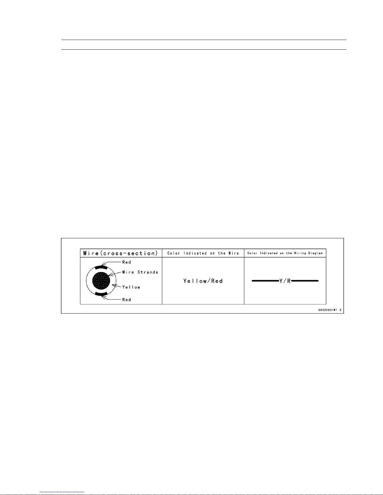
(18) Electrical Wires
All the electrical wires are either one-color or two-color. A two-color wire is identified first by the primary color and
then the stripe color. For example, a yellow wire with thin red stripes is referred to as a “yellow/red” wire; it would
be a “red/yellow” wire if the colors were reversed. Unless instructed otherwise, electrical wires must be connected to
wires of the same color.
Two-Color Electrical
(19) Inspection
When parts have been disassembled, visually inspect these parts for the following conditions or other damage. If
there is any doubt as to the condition of them, replace them with new ones.
Abrasion Crack Hardening Warp
Bent Dent Scratch Wear
Color change Deterioration Seizure
(20) Specifications
Specification terms are defined as follows:
"Standards" show dimensions or performances which brand-new parts or systems have.
"Service Limits" indicate the usable limits. If the measurement shows excessive wear or deteriorated performance,
replace the damaged parts.
(21) Instrument
Use a meter that has enough accuracy for an accurate measurement. Read the manufacture’s instructions thgoughly
before using the meter. Incorrect values may lead to improper adjustments.
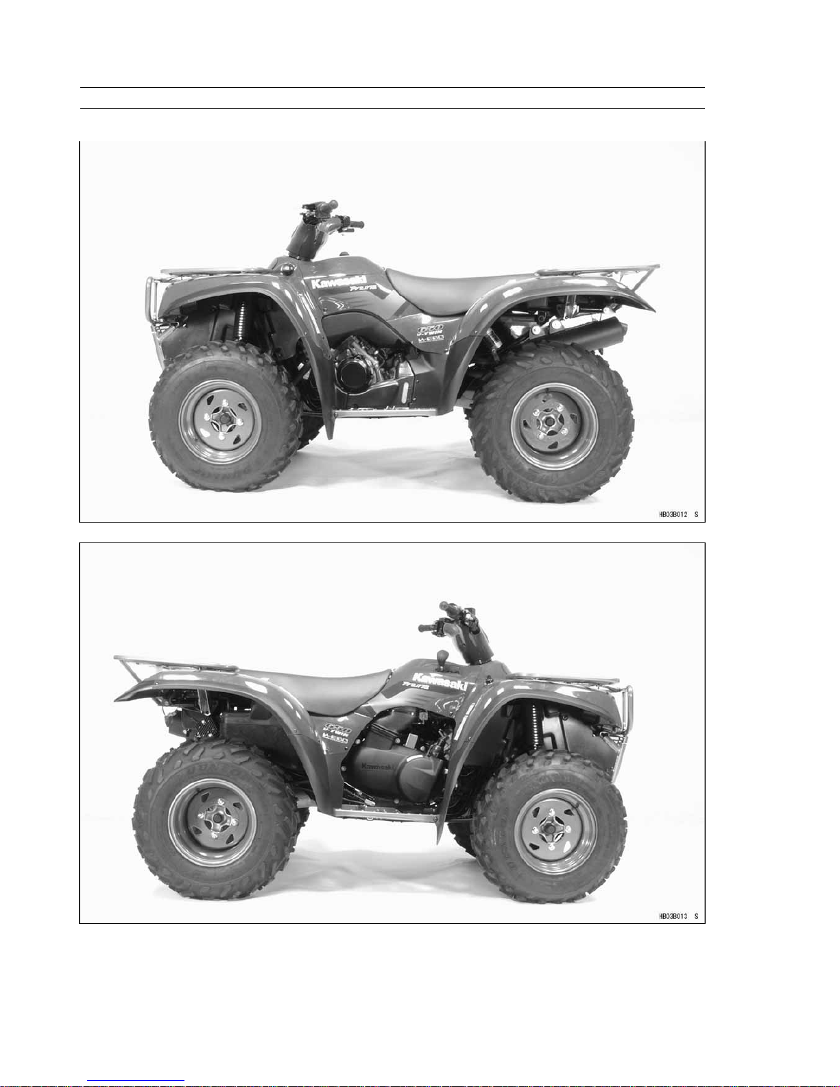
1-4 GENERAL INFORMATION
Model Identification
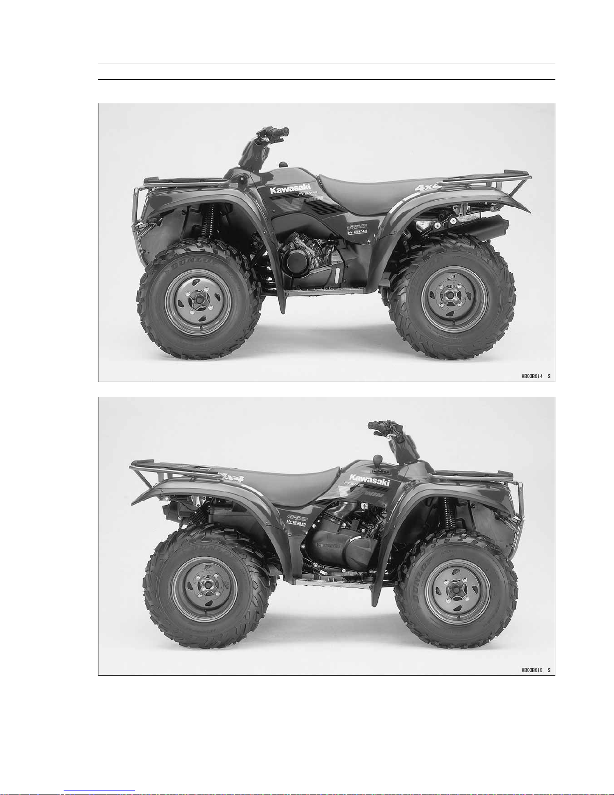
KVF650–A1
GENERAL INFORMATION 1-5
Model Identification
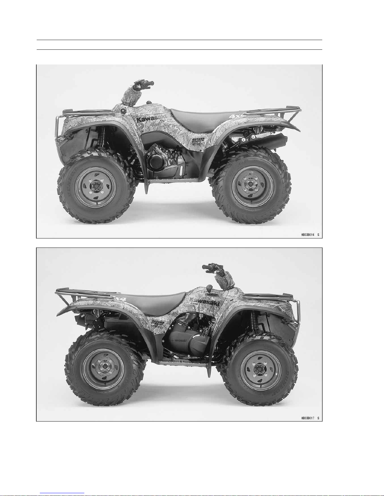
KVF650–A2
1-6 GENERAL INFORMATION
Model Identification
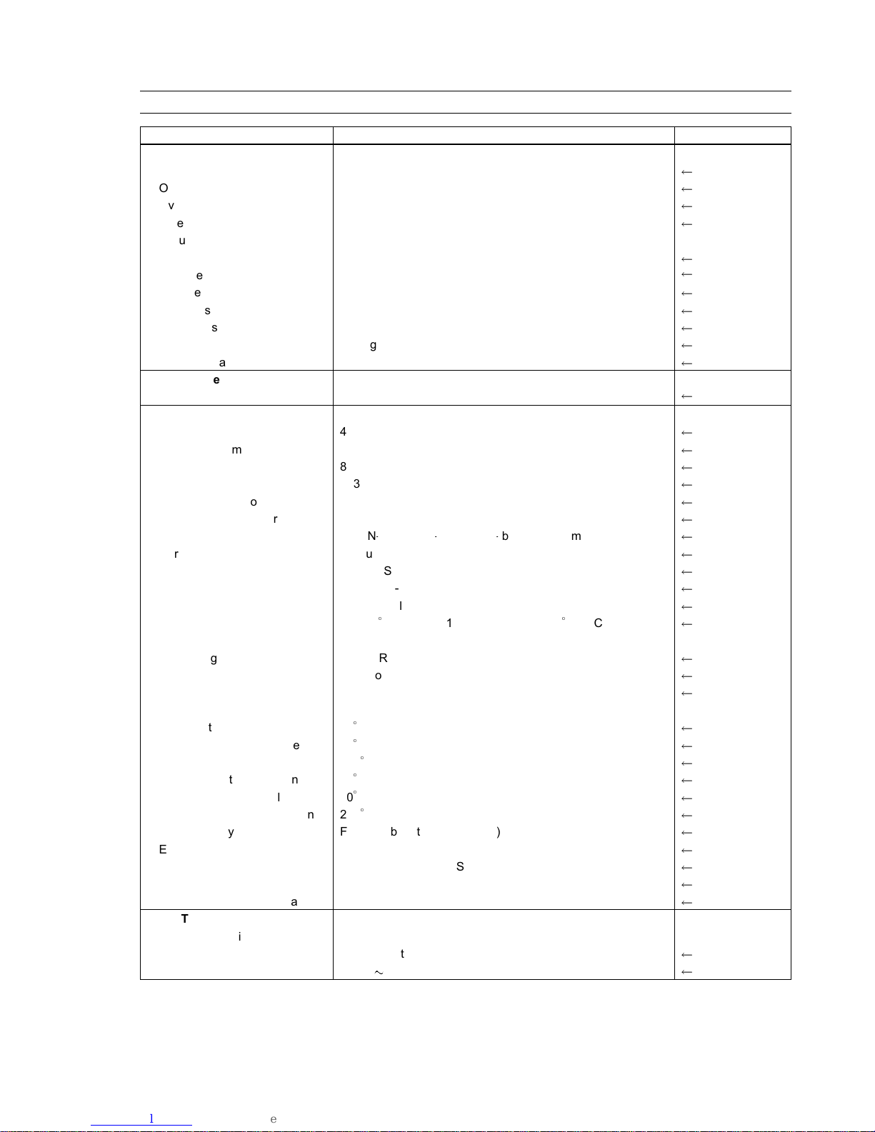
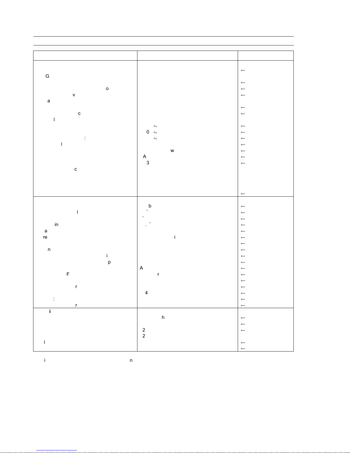
KVF650–B1, B2
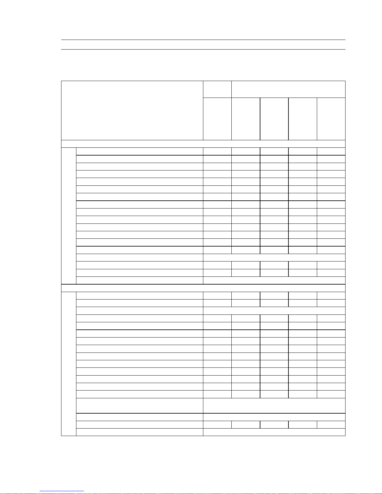
GENERAL INFORMATION 1-7
General Specifications
Items KVF650-A1, B1 KVF650-A2, B2
Dimensions:
Overall length 2 155 mm (84.84 in.)
Overall width 1 170 mm (46.06 in.)
Overall height 1 150 mm (45.28 in.)
Wheelbase 1 295 mm (50.98 in.)
Ground clearance:
Rear final gear case 193 mm (7.60 in.)
Center of frame 240 mm (9.45 in.)
Seat height 855 mm (33.66 in.)
Dry mass 274 kg (604 lb)
Curb mass: Front 155 kg (342 lb)
Rear 138 kg (304 lb)
Fuel tank capacity 17 L (4.5 US gal)
Performance:
Minimum turning radius 3.1 m (10.17 ft)
Engine:
Type 4-stroke, SOHC, V2-cylinders
Cooling system Liquid-cooled
Bore and stroke 80.0 x 63.0 mm (3.15 x 2.48 in.)
Displacement 633 mL (38.6 cu in.)
Compression ratio 9.9:1
Maximum horsepower 30.9 kW (42 PS) @6 500 r/min (rpm), (US) Maximum torque 52.1 N1m (5.3 kgf1m, 38.33 ft1lb) @4 000 r/min (rpm)
Carburetion system Carburetor, Keihin CVKR-D32
Starting system Electric Starter & Recoil Starter
Ignition system Digital DC-CDI
Timing advance Electronically advanced
Ignition timing From 5BTDC @1 100 r/min (rpm) to 28BTDC
@5 000 r/min (rpm)
Spark plug NGK CR7E, DENSO U22ESR-N
Cylinder numbering method Front to rear, 1-2
Firing order 1-2
Valve timing:
Inlet Open 30BTDC
Close 34ABDC
Duration 244
Exhaust: Open 54BBDC
Close 10ATDC
Duration 244
Lubrication system Forced lubrication (wet sump)
Engine oil: Grade API SF or SG class
API SH or SJ with JASO MA class
Viscosity
SAE10W-40
Capacity 2.05 L (2.17 US qt)
Drive Train:
Primary reduction system:
Type Belt converter
Reduction ratio 3.122 0.635
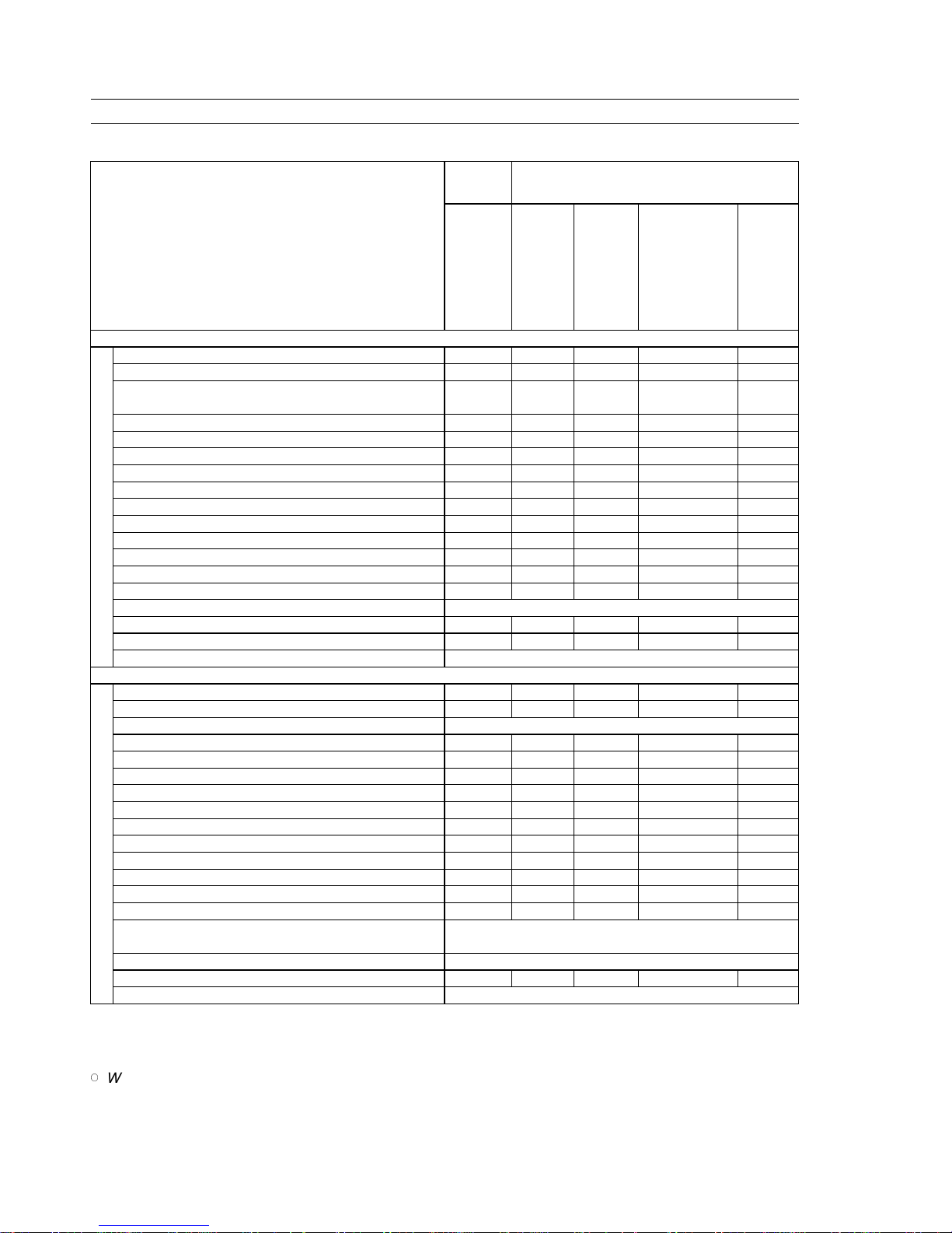
1-8 GENERAL INFORMATION
General Specifications
Items
KVF650-A1, B1 KVF650-A2, B2
Transmission:
Type 2-speed plus reverse
Gear ratios:
Forward: High 3.098 (30/26 x 29/18 x 20/12)
Low 4.833 (36/20 x 29/18 x 20/12)
Reverse: 4.028 (16/12 x 18/16 x 29/18 x 20/12)
Final drive system:
Type Shaft, 2WD/4WD
Reduction ratio 4.375 (35/8)
Overall drive ratio
Forward: High 42.32 8.61
Low 66.02 13.43
Reverse: 55.01 11.19
Front final gear case oil: Grade API SF or SG class
API SH or SJ with JASO MA class
Viscosity
SAE10W-40
Capacity 0.43 L (0.45 US qt)
Rear final gear case oil: Type MOBIL Fluid 424
MOBIL Fluid 424 or
CITGO TRANSGARD
TRACTOR
HYDRAULIC FLUID
Capacity 0.9 L (0.95 US qt)
Frame:
Type Double tubular
Caster (rake angle) 3.5
Camber 0@1 G
King pin angle 15.5
Trail 15 mm (0.59 in.)
Tread Front 914 mm (35.98 in.)
Rear 910 mm (35.83 in.)
Front tire: Type Tubeless
Size AT25 x 8 – 12
Rear tire: Type Tubeless
Size AT25 x 10 – 12
Suspension:
Front Type
MacPherson strut
Wheel travel 170 mm (6.69 in.)
Rear Type Swingarm
Wheel travel 184 mm (7.24 in.)
Brake: Front Disc (Hydraulic) x 2
Rear Enclosed Wet Multi-Plate
Electrical Equipment:
Battery 12 V 12 Ah
Headlight: Type Semi-sealed beam
Bulb 12 V 45/45 W x 2
Tail/brake light Bulb 12 V 8/27 W 12 V 5/21 W
Alternator: Type Three - phase AC
Rated output 25 A, 14 V @6 000 r/min (rpm)
Specifications are subject to change without notice, and may not apply to every country.
US: U.S.A. Model
GENERAL INFORMATION 1-9
Periodic Maintenance Chart
The scheduled maintenance must be done in accordance with this chart to keep the vehicle in good running condition.
The initial maintenance is vitally important and must not be neglected.
KVF650–A1, B1
FREQUENCY First Ser-
vice
Regular Service
OPERATION
After 10
hrs. or
100 km
(60 mi.)
of use
Every 10
days or
200 km
(120 mi.)
of use
Every 30
days or
600 km
(360 mi.)
of use
Every 90
days or
1700 km
(1100
mi.) of
use
Every
year of
use
ENGINE
Converter drive belt wear – check *
•
Converter drive belt deflection - check *
•
Drive belt failure detection system function – check*
•
Engine brake control (K-EBC) lever – check*
•
Air cleaner – service*
• •
Throttle lever play – check*
• •
Valve clearance – check*
•
Fuel system cleanliness – check*
• •
Engine oil – change *
• •
Oil filter – replace*
• •
Spark plug – clean and gap
• •
Spark arrester – clean
•
Radiator – clean*
• •
Radiator hoses, and connections – check*
•
Coolant – change* 2 years
Coolant filter of carburetor – clean
•
Fuel hoses, connections – check
•
Fuel hose – replace 4 years
CHASSIS
Joint boots – check*
• •
Rear brake pedal and lever adjustment – check*
• •
Rear brake plates – change* every 10 000 km (6 000 mi.)
Cable adjustment*
• •
Bolts and nuts – tighten
• •
Front brake pad wear – check*
• •
Brake light switch – check*
• •
Steering – check
• •
Differential control lever play– check
• •
Tire wear – check*
•
Front and rear finial gear case oil – change
• •
General lubrication*
•
Front brake fluid level – check
• •
Front brake fluid – change
•
Brake master cylinder piston assembly and dust
seal – replace
2 years
Caliper piston seal and dust seal – replace 2 years
Brake hoses, connections– check
•
Brake hose – replace 4 years
1-10 GENERAL INFORMATION
Periodic Maintenance Chart
KVF650–A2, B2
FREQUENCY
First
Service
Regular Service
OPERATION
After 10
hrs. or
100 km
(60 mi.)
of use
Every
10 days
or 200
km (120
mi.) of
use
Every
30 days
or 600
km (360
mi.) of
use
Every 90 days of
vehicle use,1700
km (1100 mi.) or
when belt indica-
tor light comes on
(100 hours)
whichever comes
first
Every
year of
use
ENGINE
Converter drive belt wear – check *
•
Converter drive belt deflection - check *
•
Drive belt failure detection system function – check*
•
(Note)
Engine brake control (K-EBC) lever – check*
•
Air cleaner – service*
• •
Throttle lever play – check*
• •
Valve clearance – check*
•
Fuel system cleanliness – check*
• •
Engine oil – change *
• •
Oil filter – replace*
• •
Spark plug – clean and gap
• •
Spark arrester – clean
•
Radiator – clean*
• •
Radiator hoses, and connections – check*
•
Coolant – change* 2 years
Coolant filter of carburetor – clean
•
Fuel hoses, connections – check
•
Fuel hose – replace 4 years
CHASSIS
Joint boots – check*
• •
Rear brake pedal and lever adjustment – check*
• •
Rear brake plates – change* every 10 000 km (6 000 mi.)
Cable adjustment*
• •
Bolts and nuts – tighten
• •
Front brake pad wear – check*
• •
Brake light switch – check*
• •
Steering – check
• •
Differential control lever play– check
• •
Tire wear – check*
•
Front and rear finial gear case oil – change
• •
General lubrication*
•
Front brake fluid level – check
• •
Front brake fluid – change
•
Brake master cylinder piston assembly and dust seal
– replace
2 years
Caliper piston seal and dust seal – replace 2 years
Brake hoses, connections– check
•
Brake hose – replace 4 years
*: Service more frequently when operated in mud, dust, or other harsh riding conditions.
•
: Clean, adjust, lubricate, torque, or replace parts as necessary.
NOTE
When the drive belt failure detection system is activated, return the vehile immediately to an authorized
Kawasaki dealer for drive belt inspection and adjustment or replacement.
GENERAL INFORMATION 1-11
Technical Information — Engine
Engine Main Specification
1. Newly designed, liquid-cooled, 633 cm
3
SOHC, 4–valve V-twin
engine produces 30.9 kW (42 PS)/6,500 rpm.
2. Over square bore and stroke of 80.0 mm x 63.0 mm contributes
to a high torque output of 52.1 N
1
m (5.3 kgf1m)/4,000 rpm and a
flat, user-friendly torque curve.
3. Off-setting the cylinders by 90-degree results in perfect primary
balance, for low vibration levels and comfortable riding.
4. Concave piston crown improves combustion efficiency.
5. Large, 30 mm intake and 26 mm exhaust valves are set at a
narrow 19-degree intake and 21-degree exhaust for a compact,
high-efficiency combustion chamber.
6. Dual, CVKR-D32 downdraft carburetors deliver smooth throttle
response and efficient fuel consumption.
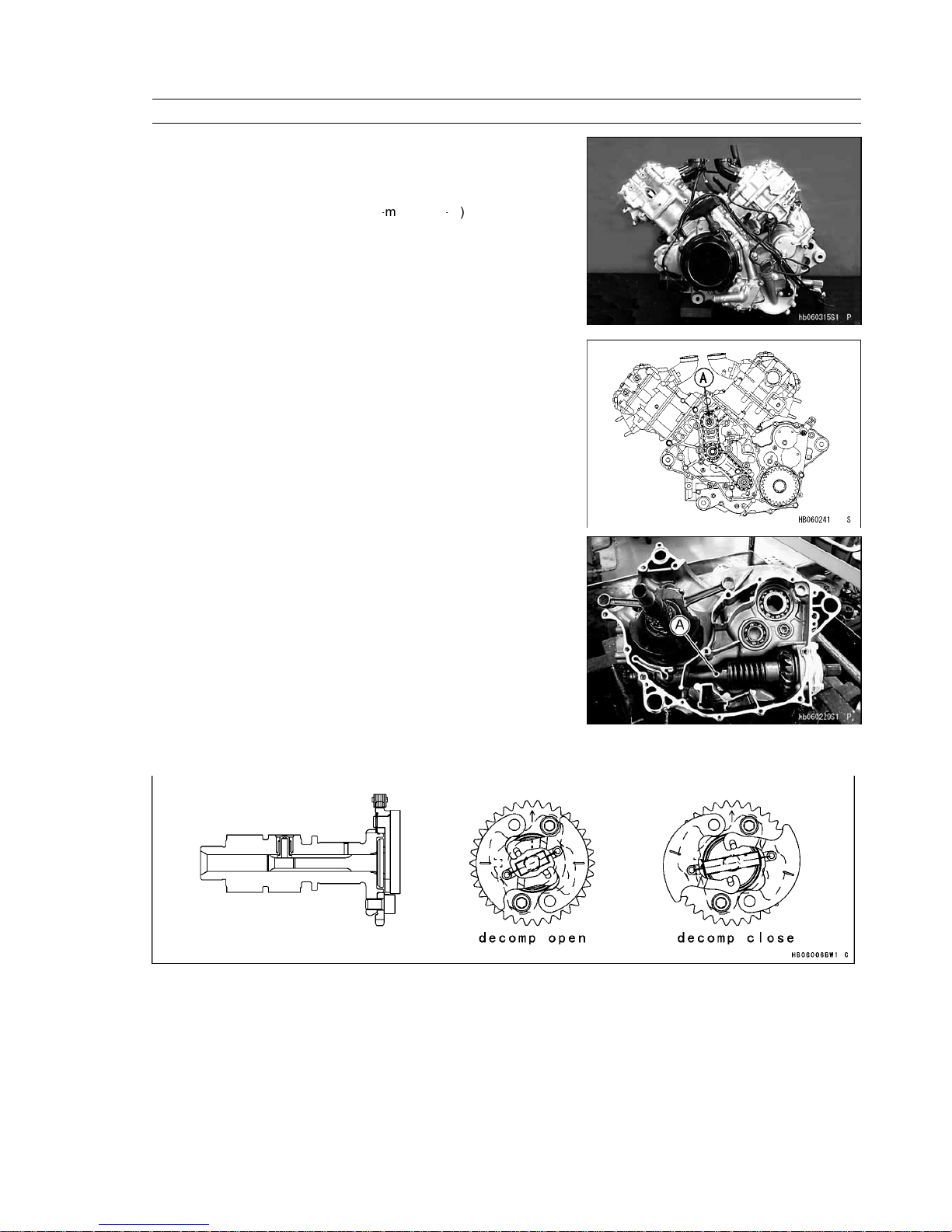
7. An intermediate sprocket is used between the crank and cams for
more compact engine design.
[A] Intermediate Shaft
8. The propeller shaft is built into the crankcase for a compact, low
mass drive train. The capacity of cam-damper is increased.
[A] Propeller Shaft
9. The KVF650A,B comes equipped with both an electric starter and a recoil starter. Together with KACR (Kawasaki
Automatic Compression Release), starting is quick and easy. The deviation of operating degree and lift is improved.
1-12 GENERAL INFORMATION
Technical Information — K-EBC System
1. Outline
This vehicle is equipped with the K-EBC (Kawasaki Engine Brake Control) system. It can assist the operator when
descending hills by supplementing the wheel brake systems with additional braking force that is produced by the engine.
When descending hills, the K-EBC system alone may not supply enough braking force. The operator should apply the
brakes to keep the speed safe for the type of terrain, visibility, operating conditions, and operator’s experience. The K-EBC
system is applied automatically under certain conditions when the throttle is released.
This system detects the ATV’s speed and running direction electrically, and when the conditions are met, a electric
actuator presses the torque converter drive pulley resulting in connecting the drive pulley with the driven pulley through
the belt and then generating braking force by the engine.
The K-EBC is a supplemental braking system when the speed is comparatively low (about 3 km/h — 20 km/h) and does
not function in reverse.
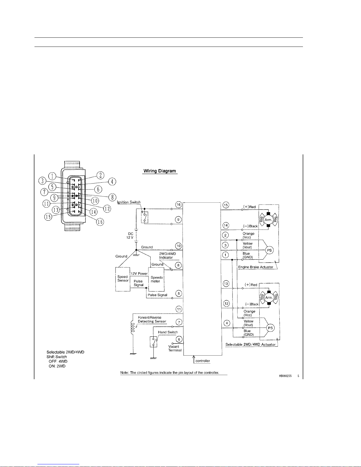
2. Wiring Diagram
The entire system is shown in the wiring diagram. The system is powered by a 12 Volt battery. Always keep the battery
connected even when the battery is discharged and operator needs to start engine. The engine can be started with the
recoil starter with the battery disconnected. However, the controller will not operate correctly.
GENERAL INFORMATION 1-13
Technical Information — K-EBC System
3. Component Parts
This system consists of a controller, actuator, lever assembly, forward/reverse detecting sensor, and a speed sensor.
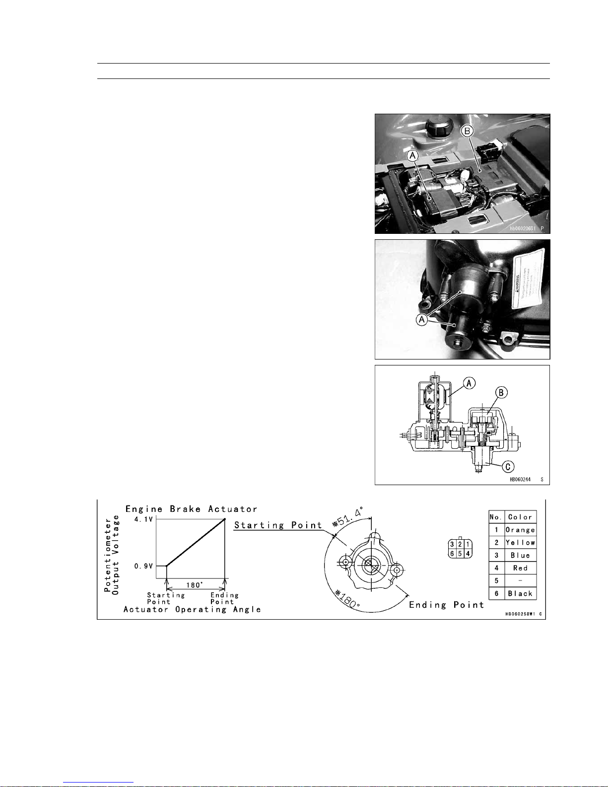
1) Controller
The controller is located under the seat and controls the engine brake
and selectable 2WD/4WD actuators.
[A] Controller
[B] Igniter
2) Engine Brake Actuator
The engine brake actuator is installed on the converter cover. It
consists of a DC motor, reduction gears, and potentiometer.
[A] Engine Brake Actuator
[A] DC Motor
[B] Potentiometer
[C] Output Shaft
Engine Brake Actuator
1-14 GENERAL INFORMATION
Technical Information — K-EBC System
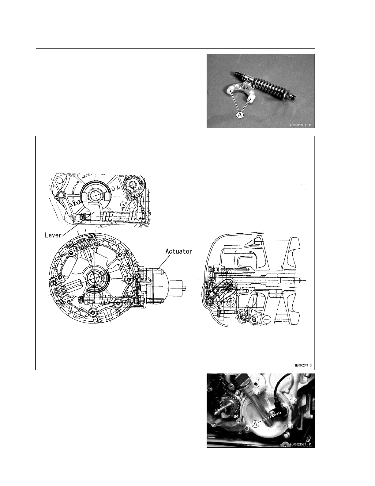
3) Lever Assembly
The lever assembly is installed in the converter cover. This transmits
the actuator’s force to the drive pulley.
[A] Contact Surface
4) Forward/Reverse Detecting Sensor
The sensor is installed on the engine and uses the principle of
electromagnetic induction. The sensor generates AC voltage according
to the speed of the rotor. The output waveforms vary in accordance
with the shape of the rotor teeth. The controller detects the running
direction from the waveforms.
[A] Forward/Reverse Detecting Sensor
GENERAL INFORMATION 1-15
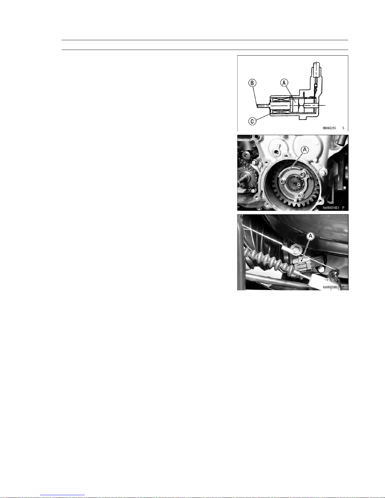
Technical Information — K-EBC System
[A] Magnet
[B] Pole
[C] Coil
[A] Rotor Tooth
5) Speed Sensor
The sensor is installed on the engine and generates pulses according
to the gap difference between the sensor and the rotating gear. The
controller calculates the vehicle’s speed by counting the pulse sent from
the speed sensor.
[A] Speed Sensor
1-16 GENERAL INFORMATION
Technical Information — K-EBC System
Description of Actuator Controller Operation
1. Outline
The actuator controller has a microprocessor that detects the vehicle speed, the state of the selectable 2WD/4WD shift
switch, ignition switch, and the forward/reverse movement of the vehicle in order to control the engine brake and selectable
2WD/4WD actuators.
2. Engine Brake Actuator Controls
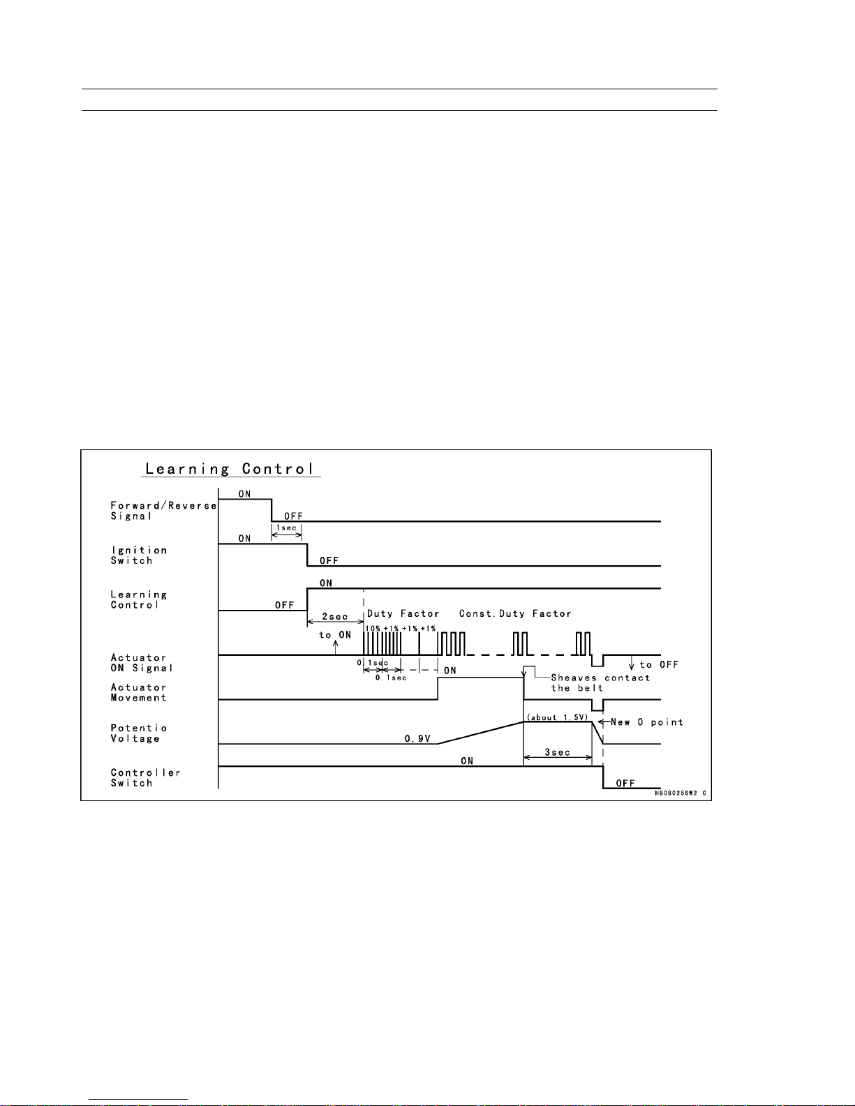
2–1 Learning Control
After the signal from the forward/reverse detecting sensor stops and 1 second elapses, turning the ignition switch OFF
causes the learning control to start.
After the ignition switch is turned OFF and a prescribed length of time elapses, current is applied to the actuator at a
prescribed duty factor in order to move the actuator towards engine brake ON position.
After the application of the current, if the actuator does not move within a prescribed length of time, the duty factor
increases in an attempt to move the actuator. This process is repeated until the actuator moves.
Once the actuator starts moving, the actuator continues to move at that duty factor.
The lever moves the drive pulley’s movable sheave until it contacts the belt. After contact with the belt, the actuator
cannot move any further because of the small duty cycle, and no more play in the system.
After the actuator stops moving, and a prescribed length of time elapses, the voltage (0 point = datum point) of the
potentiometer that is installed in the actuator is recorded on the EEPROM. The actuator returns to the engine brake OFF
position and the power to the controller turns OFF by the power ON/OFF circuit.
Learning Control
GENERAL INFORMATION 1-17
Technical Information — K-EBC System
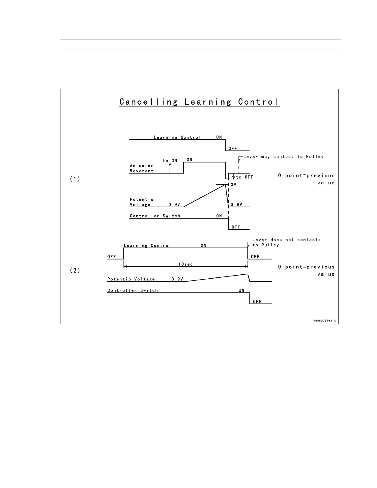
In case the Learning Control has failed, the previously learned value is used for the 0-point position of the actuator.
1) When the voltage of the potentiometer that is installed in the actuator exceeds a prescribed voltage.
2) When the learning control has not finished within 10 seconds.
Canceling Learning Control
1-18 GENERAL INFORMATION
Technical Information — K-EBC System
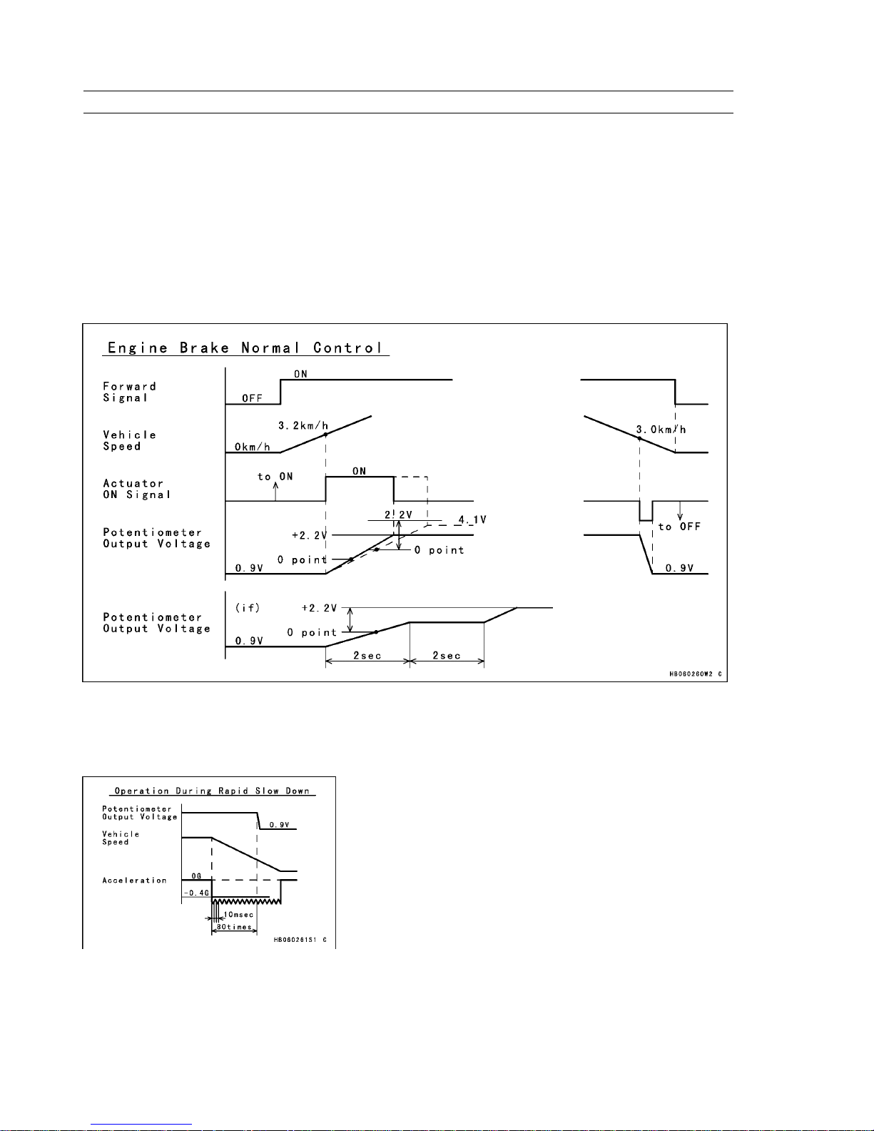
2–2 Normal Control
After forward movement is detected from the forward/reverse detecting sensor:
1) If the vehicle speed is higher than the prescribed value, the actuator moves towards engine brake ON position.
2) If the vehicle speed is less than the prescribed value, the actuator moves towards engine brake OFF position.
The maximum movement of the actuator ranges between the starting position and the ending position. The actuator
moves from the learned 0-point position to a position to which a prescribed voltage has been added.
However, if the sum of the learned value and the prescribed voltage exceeds the voltage of the ending position, the
actuator stops at the ending position.
During actuator operation, if the target value is not attained even if the actuator is moved longer than a prescribed
length of time, the controller stops the actuator temporarily. After a prescribed length of time, the controller resumes the
movement of the actuator. This process is repeated until the actuator attains the target value.
Engine Brake Normal Control
2–3 Operation During Rapid Slow Down
This control works to avoid the engine stopping when the vehicle speeds down rapidly.
When the actuator is in the engine brake ON position, if the deceleration of the vehicle is greater than a prescribed rate
and is detected within an interval time of 10 milliseconds, the actuator returns to engine brake OFF position.
Operation During Rapid Slow Down
GENERAL INFORMATION 1-19
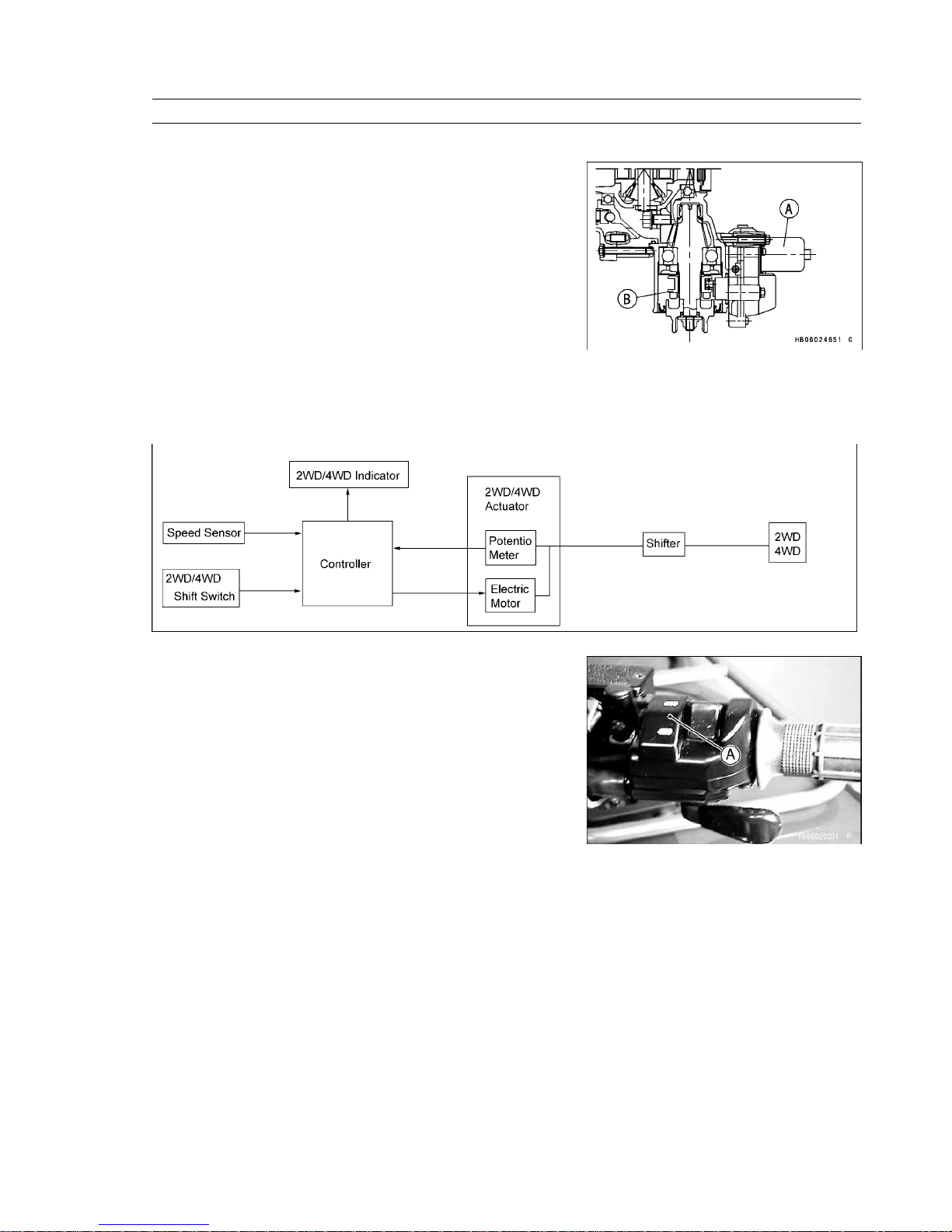
Technical Information — Selectable 2WD/4WD
1. Feature
Selectable 2WD/4WD system allows easy changing between 2WD
and 4WD drive systems to suit changing terrain and applications.
[A] 2WD/4WD Actuator
[B] Shifter
2. System Outline and Component Parts
This system consists of a 2WD/4WD shift switch, speed sensor, 2WD/4WD actuator, controller, and indicator for 2WD/
4WD.
See the wiring diagram in the K-EBC chapter.
(1) 2WD/4WD Shift Switch
The 2WD/4WD shift switch is installed on the right side of the
handlebar. This switch should be used when the vehicle is stopped.
(2) Speed Sensor
The sensor is installed on the right rear of the engine. It generates
pulses according to the gap difference between the sensor and the
rotating gear.
1-20 GENERAL INFORMATION
Technical Information — Selectable 2WD/4WD
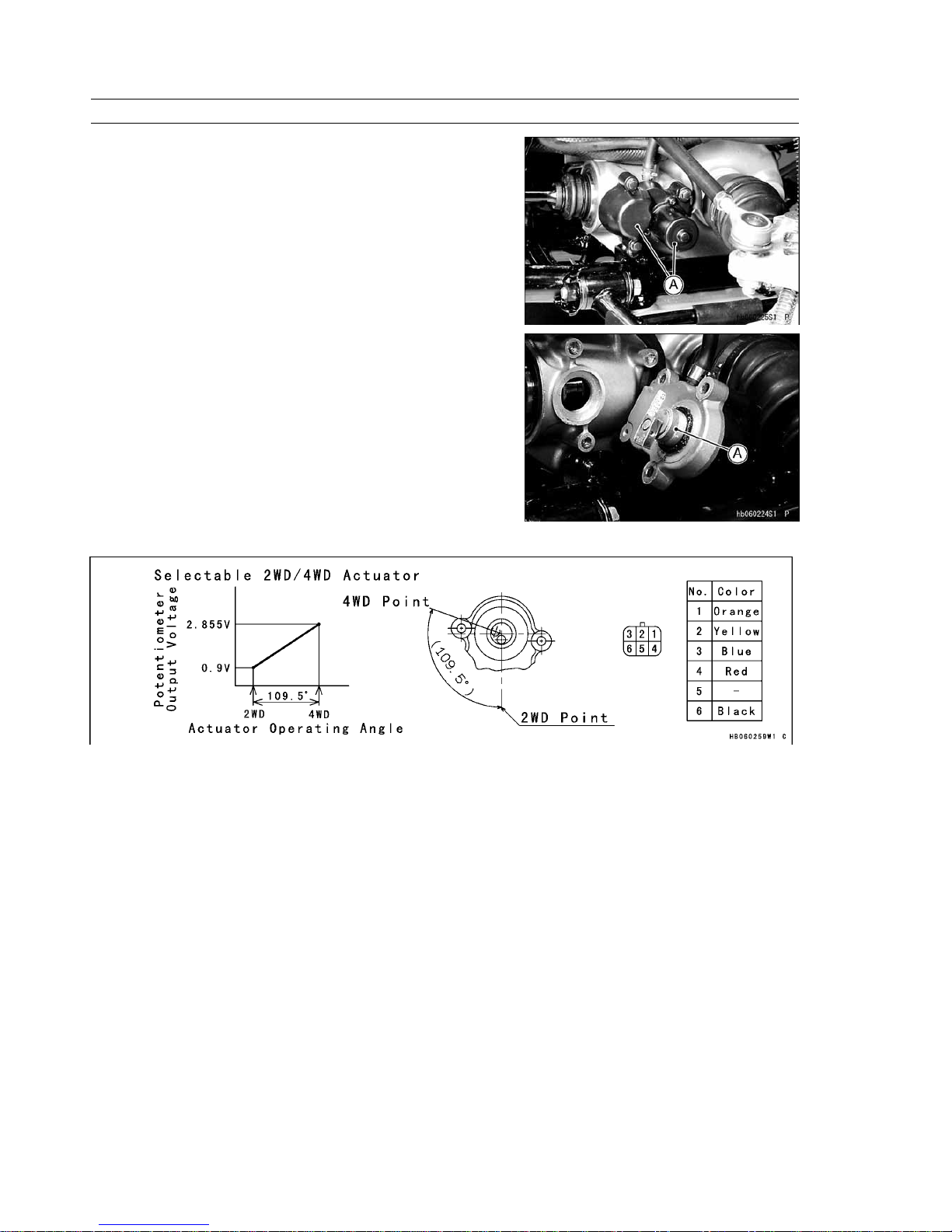
(3) 2WD/4WD Actuator
The actuator is installed on the front gear case. It consists of a DC
motor, reduction gears, and potentiometer.
[A] 2WD/4WD Actuator
[A] Output Shaft of Actuator
This figure shows the operation of the actuator.
(4) Controller
Refer to the K-EBC chapter.
GENERAL INFORMATION 1-21
Technical Information — Selectable 2WD/4WD
2. Selectable 2WD/4WD Actuator Control
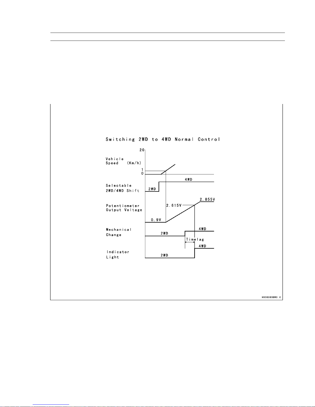
2–1 Switching 2WD to 4WD Control
1) Normal Control
This control operates only if the vehicle speed is within the range of 1 km/h and 20 km/h, and the selectable 2WD/4WD
shift switch is in 4WD.
The movement range of the actuator is between the starting position for 2WD, and the ending position for 4WD.
During actuator operation, at the time the potentiometer voltage becomes greater than a prescribed voltage, the indicator
light on the multifunction meter changes from 2WD to 4WD.
Selectable 2WD/4WD Normal Control
1-22 GENERAL INFORMATION
Technical Information — Selectable 2WD/4WD
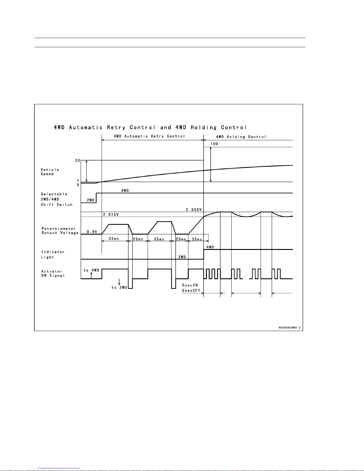
2) 4WD Automatic Retry Control
During actuator operation, if the actual value does not reach the indicator light switching voltage even after the actuator
moves longer than a prescribed length of time, the actuator returns temporarily in the 2WD direction. After a prescribed
length of time elapses, the actuator moves again in the 4WD direction. This process is repeated until the actuator reaches
the indicator light switching voltage.
This control applies to vehicle speeds that range between 1 km/h and 20 km/h.
4WD Automatic Retry Control
GENERAL INFORMATION 1-23
Technical Information — Selectable 2WD/4WD
3) 4WD Holding Control
During the implementation of "4WD Automatic Retry Control", control transfers to "4WD Holding Control" at the time the
potentiometer voltage becomes greater than the indicator light switching voltage and the actuator movement is less than
the ending position.
If the actuator is pushed back toward the 2WD direction, this control moves the actuator in the 4WD direction in order
to return it to the final position. The interval times of the actuator movement consist of ON time toward 4WD and OFF
times, which are repeated until the potentiometer voltage reaches the final position.
This control applies to vehicle speeds that range between 1 km/h and 100 km/h. The control ends when the potentiometer
voltage reaches the ending position voltage.
When the vehicle speed is above 20 km/h, control continues even if the selectable 2WD/4WD shift switch is switched
to 2WD. When the vehicle speed is between 1 km/h to 20 km/h, this control stops and transfers to 2WD control.
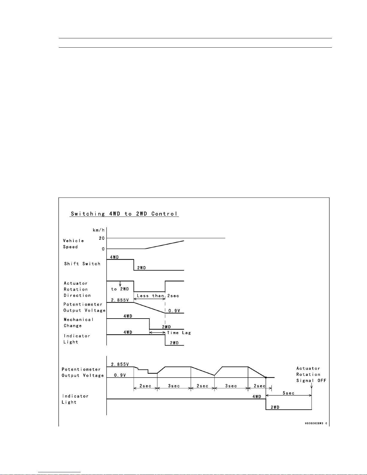
2–2 Switching 4WD to 2WD Control
This control is in effect only when the vehicle speed is between 0 km/h and 20 km/h, and the selectable 2WD/4WD shift
switch is in 2WD.
The movement range of the actuator is between the starting position for 4WD, and the ending position for 2WD.
During actuator operation, at the time the potentiometer output voltage is ending position voltage, the indicator light on
the multifunction meter changes from 4WD to 2WD.
During actuator operation, if the potentiometer output voltage does not reach the ending position voltage even after the
actuator moves longer than a prescribed length of time, the actuator returns temporarily in the 4WD direction, and moves
again in the 2WD direction. This process is repeated until the actuator reaches 2WD position.
Switching 4WD to 2WD Control
 Loading...