

Kawasaki PRAIRIE 360, KVF 360 Service Manual

PRAIRIE 360
KVF 360
All Terrain Vehicle
Service Manual
All rights reserved. No parts of this publication may be reproduced, stored in a retrieval system, or transmitted in any
form or by any means, electronic mechanical photocopying, recording or otherwise, without the prior written permission of
Quality Assurance Department/Consumer Products & Machinery Company/Kawasaki Heavy Industries, Ltd., Japan.
No liability can be accepted for any inaccuracies or omissions in this publication, although every possible care has been
taken to make it as complete and accurate as possible.
The right is reserved to make changes at any time without prior notice and without incurring an obligation to make
such changes to products manufactured previously. See your dealer for the latest information on product improvements
incorporated after this publication.
All information contained in this publication is based on the latest product information available at the time of publication.
Illustrations and photographs in this publication are intended for reference use only and may not depict actual model
component parts.
© 2002 Kawasaki Heavy Industries, Ltd. Second Edition (1) : Jun. 20, 2002 (K)
LIST OF ABBREVIATIONS
A ampere(s) lb pounds(s)
ABDC after bottom dead center m meter(s)
AC alternating current min minute(s)
ATDC after top dead center N newton(s)
BBDC before bottom dead center Pa pascal(s)
BDC bottom dead center PS horsepower
BTDC before top dead center psi pound(s) per square inch
C degree(s) Celcius r revolution
DC direct current rpm revolution(s) per minute
F farad(s) TDC top dead center
F degree(s) Fahrenheit TIR total indicator reading
ft foot, feet V volt(s)
g gram(s) W watt(s)
h hour(s)
L liter(s)
ohm(s)
Read OWNER’S MANUAL before operating.

EMISSION CONTROL INFORMATION
To protect the environment in which we all live, Kawasaki has incorporated crankcase emission (1) and exhaust emission
(2) control systems in compliance with applicable regulations of the California Air Resources Board.
1. Crankcase Emission Control System
A sealed-type crankcase emission control system is used to eliminate blow-by gases. The blow-by
gases are led to the breather chamber through the crankcase. Then, it is led to the air cleaner.
Oil is separated from the gases while passing through the inside of the breather chamber from the
crankcase, and then returned back to the bottom of crankcase.
2. Exhaust Emission Control System
The exhaust emission control system applied to this engine family is engine modifications that consist
of a modified carburetor and an ignition system having optimum ignition timing characteristics.
The carburetor has been calibrated to provide lean air/fuel mixture characteristics and optimum fuel
economy with a suitable air cleaner and exhaust system.
A maintenance free ignition system provides the most favorable ignition timing and helps maintain a
thorough combustion process within the engine which contributes to a reduction of exhaust pollutants
entering the atomosphere.
The Clean Air Act, which is the Federal law covering motor vehicle pollution, contains what is commonly referred to as
the Act’s "tampering provisions."
"Sec. 203(a) The following acts and the causing thereof are prohibited...
(3)(A) for any person to remove or render inoperative any device or element of design installed on or
in a motor vehicle or motor vehicle engine in compliance with regulations under this title prior to
its sale and delivery to the ultimate purchaser, or for any manufacturer or dealer knowingly to
remove or render inoperative any such device or element of design after such sale and delivery
to the ultimate purchaser.
(3)(B) for any person engaged in the business of repairing, servicing, selling, leasing, or trading motor
vehicles or motor vehicle engines, or who operates a fleet of motor vehicles knowingly to remove
or render inoperative any device or element of design installed on or in a motor vehicle or motor
vehicle engine in compliance with regulations under this title following its sale and delivery to the
ultimate purchaser..."
NOTE
The phrase "remove or render inoperative any device or element of design" has been generally
interpreted as follows:
1.Tampering does not include the temporary removal or rendering inoperative of devices or
elements of design in order to perform maintenance.
2.Tampering could include:
a.Maladjustment of vehicle components such that the emission standards are exceeded.
b.Use of replacement parts or accessories which adversely affect the performance or
durability of the vehicle.
c.Addition of components or accessories that result in the vehicle exceeding the standards.
d.Permanently removing, disconnecting, or rendering inoperative any component or element
of design of the emission control systems.
WE RECOMMEND THAT ALL DEALERS OBSERVE THESE PROVISIONS OF FEDERAL LAW, THE VIOLATION OF
WHICH IS PUNISHABLE BY CIVIL PENALTIES NOT EXCEEDING $10,000 PER VIOLATION.

PLEASE DO NOT TAMPER WITH NOISE CONTROL SYSTEM
(US MODEL only)
To minimize the noise emissions from this product, Kawasaki has equipped it with effective intake and exhaust silencing
systems. They are designed to give optimum performance while maintaining a low noise level. Please do not remove
these systems, or alter them in any which results in an increase in noise level.
Foreword
This manual is designed primarily for use by trained
mechanics in a properly equipped shop. However, it
contains enough detail and basic information to make
it useful to the owner who desires to perform his own
basic maintenance and repair work. A basic knowledge
of mechanics, the proper use of tools, and workshop
procedures must be understood in order to carry out
maintenance and repair satisfactorily. Whenever the
owner has insufficient experience or doubts his ability to
do the work, all adjustments, maintenance, and repair
should be carried out only by qualified mechanics.
In order to perform the work efficiently and to avoid
costly mistakes, read the text, thoroughly familiarize
yourself with the procedures before starting work, and
then do the work carefully in a clean area. Whenever
special tools or equipment are specified, do not use
makeshift tools or equipment. Precision measurements
can only be made if the proper instruments are used,
and the use of substitute tools may adversely affect safe
operation.
For the duration of the warranty period, we recommend that all repairs and scheduled maintenance be
performed in accordance with this service manual. Any
owner maintenance or repair procedure not performed in
accordance with this manual may void the warranty.
To get the longest life out of your vehicle:
Follow the Periodic Maintenance Chart in the Service
•
Manual.
Be alert for problems and non-scheduled maintenance.
•
Use proper tools and genuine Kawasaki Vehicle parts.
•
Special tools, gauges, and testers that are necessary
when servicing Kawasaki vehicles are introduced by
the Special Tool Catalog or Manual. Genuine parts
provided as spare parts are listed in the Parts Catalog.
Follow the procedures in this manual carefully. Don’t
•
take shortcuts.
Remember to keep complete records of maintenance
•
and repair with dates and any new parts installed.
How to Use This Manual
In this manual, the product is divided into its major systems and these systems make up the manual’s chapters.
The Quick ReferenceGuideshowsyoualloftheproduct’s
system and assists in locating their chapters. Each chapter in turn has its own comprehensive Table of Contents.
For example, if you want ignition coil information, use
the Quick ReferenceGuidetolocate the Electrical System
chapter. Then, use the Tableof Contents on the first page
of the chapter to find the Ignition Coil section.
Whenever you see these WARNING and CAUTION
symbols, heed their instructions! Always follow safe
operating and maintenance practices.
This warning symbol identifies special instruc-
tions or procedures which, if not correctly fol-
lowed, could result in personal injury, or loss of
life.
CAUTION
This caution symbol identifies special instruc-
tions or procedures which, if not strictly ob-
served, could result in damage to or destruction
of equipment.
This manual contains four more symbols (in addition to
WARNING and CAUTION) which will help you distinguish
different types of information.
NOTE
This note symbol indicates points of particular interest for more efficient and convenient operation.
Indicates a procedural step or work to be done.
•
Indicates a procedural sub-step or how to do the work
of the procedural step it follows. It also precedes the
text of a NOTE.
Indicates a conditionalsteporwhataction to take based
on the results of the test or inspection in the procedural
step or sub-step it follows.
In most chapters an exploded view illustration of the
system components follows the Table of Contents. In
these illustrations you will find the instructions indicating
which parts require specified tightening torque, oil, grease
or a locking agent during assembly.


GENERAL INFORMATION 1-1
General Information
Table of Contents
Before Servicing................................................................................................................................................................1-2
Model Identification...........................................................................................................................................................1-4
General Specifications......................................................................................................................................................1-6
Special Tools and Sealant.................................................................................................................................................1-8
Unit Conversion Table.....................................................................................................................................................1-14
1

1-2 GENERAL INFORMATION
Before Servicing
Before starting to perform an inspection service or carry out a disassembly and reassembly operation on a vehicle,
read the precautions given below. To facilitate actual operations, notes, illustrations, photographs, cautions, and detailed
descriptions havebeen included in each chapter wherever necessary. This section explains the items that require particular
attention during the removal and reinstallation or disassembly and reassembly of general parts.
Especially note the following:
(1) Dirt
Before removal and disassembly, clean the vehicle. Any dirt entering the engine will shorten the life of the vehicle.
For the same reason, before installing a new part, clean off any dust or metal filings.
(2) Battery Ground
Disconnect the ground (–) wire from the battery before performing any disassembly operations on the vehicle. This
prevents the engine from accidentally turning over while work is being carried out, sparks from being generated while
disconnecting the wires from electrical parts, as well as damage to the electrical parts themselves. For reinstallation,
first connect the positive wire to the positive (+) terminal of the battery
(3) Installation, Assembly
Generally, installation or assembly is the reverse of removal or disassembly. However, if installation or assembly
sequence is given in this Service Manual, follow it. Note parts locations and cable, wire, and hose routing during
removal or disassembly so they can be installed or assembled in the same way. It is preferable to mark and record
the locations and routing whenever possible.
(4) Tightening Sequence
When installing bolts, nuts, or screws for which a tightening sequence is given in this Service Manual, make sure
to follow the sequence. When installing a part with several bolts, nuts, or screws, start them all in their holes and
tighten them to a snug fit, thus ensuring that the part has been installed in its proper location. Then, tighten them
to the specified torque in the tightening sequence and method indicated. If tightening sequence instructions are not
given, tighten them evenly in a cross pattern. Conversely, to remove a part, first loosen all the bolts, nuts, or screws
that are retaining the part a 1/4–turn before removing them.
(5) Torque
When torque values are given in this Service Manual, use them. Either too little or too much torque may lead to
serious damage. Use a good quality, reliable torque wrench.
(6) Force
Common sense should dictate how much force is necessary in assembly and disassembly. If a part seems especially
difficult to remove or install, stop and examine what may be causing the problem. Whenever tapping is necessary, tap
lightly using a wooden or plastic-faced mallet. Use an impact driver for screws (particularly for the removing screws
held by non-permanent locking agent) in order to avoid damaging the screw heads.
(7) Edges
Watch for sharp edges, as they could cause injury through careless handling, especially during major engine
disassembly and assembly. Use a clean piece of thick cloth when lifting the engine or turning it over.
(8) High-Flash Point Solvent
A high-flash point solvent is recommended to reduce fire danger. A commercial solvent commonly available in North
America is standard solvent (generic name). Always follow manufacturer and container directions regarding the use
of any solvent.
(9) Gasket, O-Ring
Replace a gasket or an O-ring with a new part when disassembling. Remove any foreign matter from the mating
surface of the gasket or O-ring to ensure a perfectly smooth surface to prevent oil or compression leaks.
(10) Liquid Gasket, Locking Agent
Clean and prepare surfaces where liquid gasket or non-permanent locking agent will be used. Apply them sparingly.
Excessive amount may block engine oil passages and cause serious damage.
(11) Press
When using a press or driver to install a part such as a wheel bearing, apply a small amount of oil to the area
where the two parts come in contact to ensure a smooth fit.
(12) Ball Bearing and Needle Bearing
Do not remove a ball bearing or a needle bearing unless it is absolutely necessary. Replace any ball or needle
bearings that were removed with new ones. Install bearings with the manufacturer and size marks facing out, applying
pressure evenly with a suitable driver. Apply force only to the end of the race that contacts the press fit portion, and
press it evenly over the base component.
(13) Oil Seal and Grease Seal
Replace any oil or grease seals that were removed with new ones, as removal generally damages seals. Oil or
grease seals should be pressed into place using a suitable driver, applying a force uniformly to the end of seal until
the face of the seal is even with the end of the hole, unless instructed otherwise. When pressing in an oil or grease
seal which has manufacturer’s marks, press it in with the marks facing out.
GENERAL INFORMATION 1-3
Before Servicing
(14) Circlip, Retaining Ring, and Cotter Pin
When installing circlips and retaining rings, take care to compress or expand them only enough to install them and
no more. Install the circlip with its chamfered side facing load side as well.
Replace any circlips, retaining rings, and cotter pins that were removed with new ones, as removal weakens and
deforms them. If old ones are reused, they could become detached while the vehicle is driven, leading to a major
problem.
(15) Lubrication
Engine wear is generally at its maximum while the engine is warming up and before all the sliding surfaces have
an adequate lubricative film. During assembly, make sure to apply oil to any sliding surface or bearing that has been
cleaned. Old grease or dirty oil could have lost its lubricative quality and may contain foreign particles that act as
abrasives; therefore, make sure to wipe it off and apply fresh grease or oil. Some oils and greases in particular should
be used only in certain applications and may be harmful if used in an application for which they are not intended.
(16) Direction of Engine Rotation
To rotate the crankshaft manually, make sure to do so in the direction of positive rotation. Positive rotation is
counterclockwiseas viewed from the left side of the engine. To carry out proper adjustment, it is furthermore necessary
to rotate the engine in the direction of positive rotation as well.
(17) Replacement Parts
When there is a replacement instruction, replace these parts with new ones every time they are removed.
Replacement parts will be damaged or lose their original function once they are removed. Therefore, always
replace these parts with new ones every time they are removed. Although the previously mentioned gasket, O-ring,
ball bearing, needle bearing, grease seal, oil seal, circlip, and cotter pin have not been so designated in their respective
text, they are replacement parts.
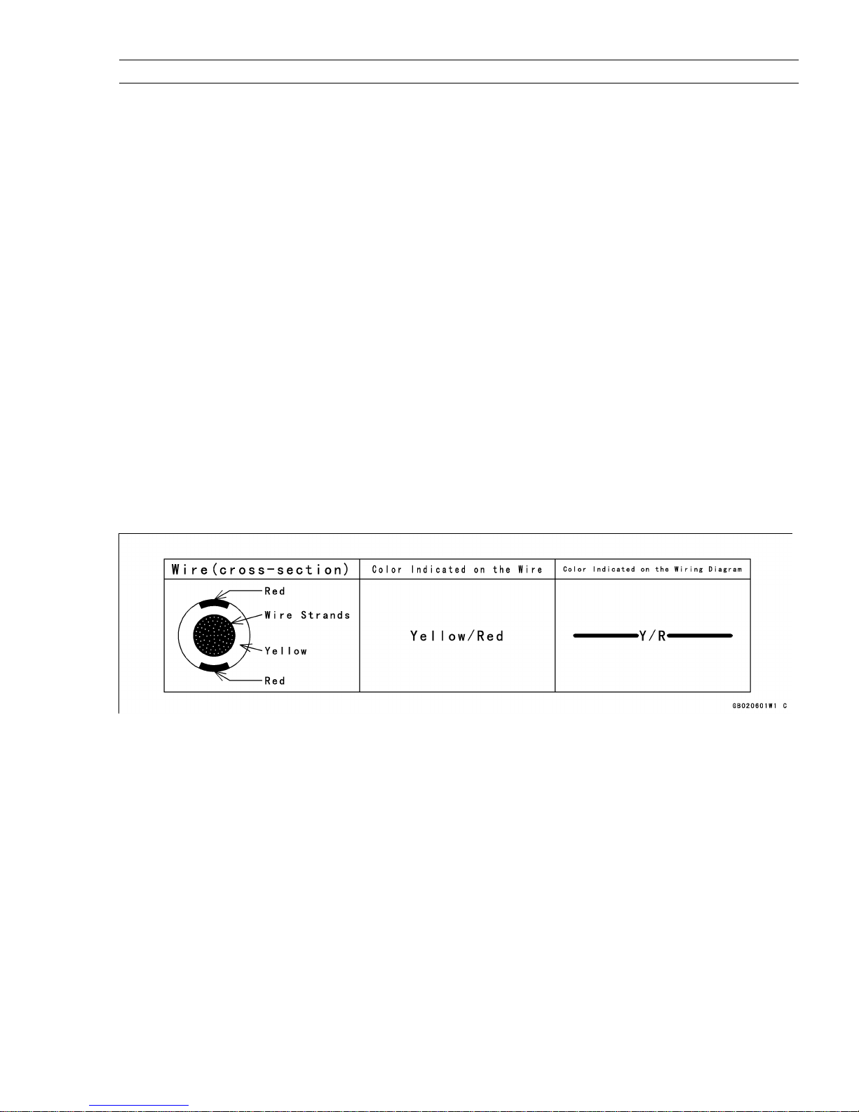
(18) Electrical Wires
All the electrical wires are either one-color or two-color. A two-color wire is identified first by the primary color and
then the stripe color. For example, a yellow wire with thin red stripes is referred to as a “yellow/red” wire; it would
be a “red/yellow” wire if the colors were reversed. Unless instructed otherwise, electrical wires must be connected to
wires of the same color.
Two-Color Electrical
(19) Inspection
When parts have been disassembled, visually inspect these parts for the following conditions or other damage. If
there is any doubt as to the condition of them, replace them with new ones.
Abrasion Crack Hardening Warp
Bent Dent Scratch Wear
Color change Deterioration Seizure
(20) Specifications
Specification terms are defined as follows:
"Standards" show dimensions or performances which brand-new parts or systems have.
"Service Limits" indicate the usable limits. If the measurement shows excessive wear or deteriorated performance,
replace the damaged parts.
1-4 GENERAL INFORMATION
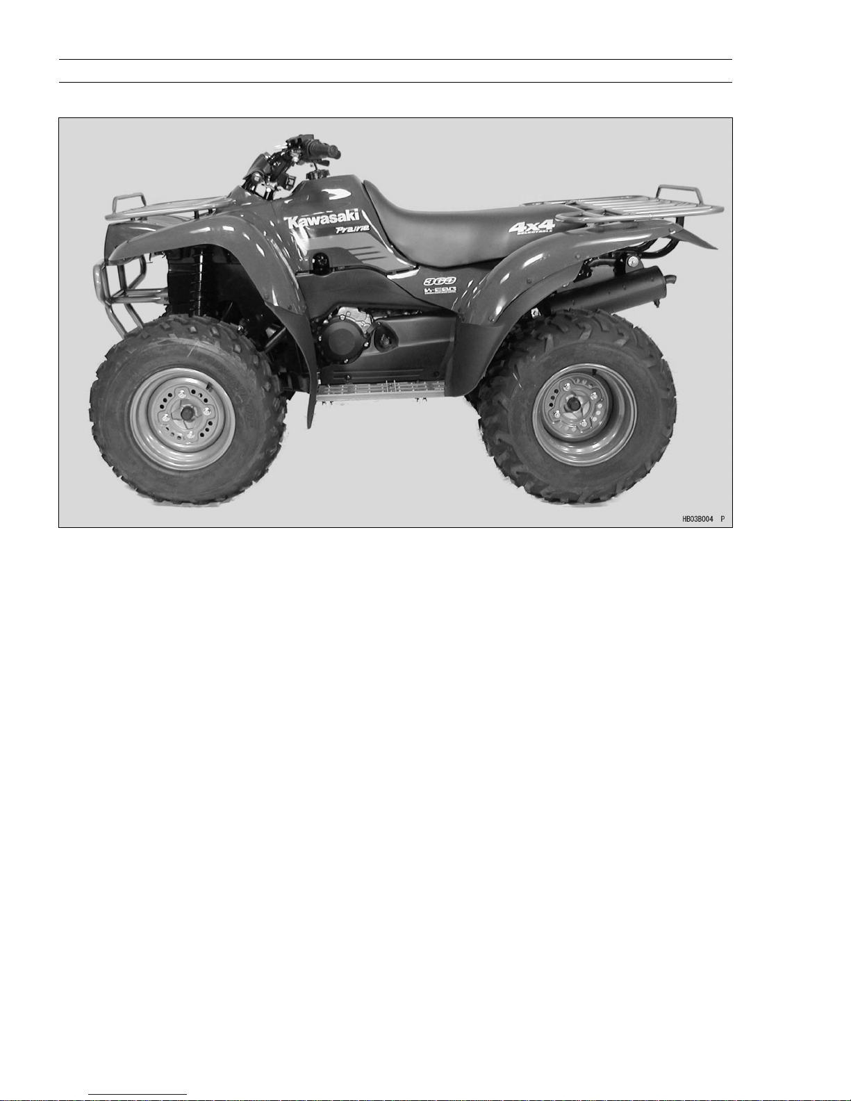
Model Identification
KVF360–A1
Model Identification
KVF360–A1
GENERAL INFORMATION 1-5
1-6 GENERAL INFORMATION
General Specifications
Items KVF360-A1
Dimensions:
Overall length
Overall width 1205 mm (47.44 in.)
Overall height 1175 mm (46.26 in.)
Wheelbase 1250 mm (49.21 in.)
Ground clearance:
Rear final gear case 195 mm (7.68 in.)
Center of frame 250 mm (9.84 in.)
Seat height 890 mm (35.04 in.)
Dry mass 274 kg (604 lb), (US) 272.5 kg (601 lb)
Curb mass: Front 154 kg (340 lb), (US) 153 kg (337 lb)
Rear 135 kg (298 lb), (US) 134 kg (295 lb)
Fuel tank capacity 13.5 L (3.6 US gal)
Performance:
Minimum turning radius 3.1 m (10.17 ft)
Engine:
Type 4-stroke, SOHC, 1-cylinder
Cooling system Air-cooled
Bore and stroke 80.0 x 72.0 mm (3.15 x 2.83 in.)
Displacement 362 mL (22.1 cu in.)
Compression ratio 8.3 : 1
Maximum horsepower 15.7 kW (21.4 PS) @7000 r/min (rpm), (US) Maximum torque 26.1 N1m (2.66 kgf
Carburetion system Carburetor, Keihin CVK34
Starting system Electric Starter & Recoil Starter
Ignition system DC-CDI
Timing advance Electronically advanced
Ignition timing From 10BTDC @1300 r/min (rpm) to 30
Spark plug NGK DPR8EA-9
Valve timing:
Inlet Open 38
Close 58ABDC
Duration 276
Exhaust: Open 68
Close 28ATDC
Duration 276
Lubrication system Forced lubrication (wet sump)
Engine oil: Type API SF or SG
Viscosity SAE 10W-40
Capacity 2.3 L (2.17 US qt)
Drive Train:
Primary reduction system:
Type Belt converter
Reduction ratio 3.122 0.635
2065 mm (81.30 in.)
1
m, 19.25 ft1lb) @4500 r/min (rpm)
BTDC
BBDC
API SH or SJ with JASO MA
BTDC @5 000 r/min (rpm)
General Specifications
GENERAL INFORMATION 1-7
Items
KVF360-A1
Transmission:
Type 2-speed plus reverse
Gear ratios:
Forward: High 3.548 (30/26 x 29/18 x 21/11)
Low 5.536 (36/20 x 29/18 x 21/11)
Reverse 4.613 (16/12 x 18/16 x 29/18 x 21/11)
Final drive system:
Type Shaft, 2WD/4WD
Reduction ratio 4.375 (35/8)
Overall drive ratio:
Forward: High 48.474 9.859
Low 75.619
Reverse 63.016
15.380
12.817
Front final gear case oil: Type API SF or SG
API SH or SJ with JASO MA
Viscosity SAE 10W-40
Capacity 0.43 L (0.45 US qt)
Rear final gear case oil: Type MOBIL Fluid 424 or Kawa Chem Gear & Wet Brake Oil
(CITGO TRANSGARD TRACTOR HYDRAULIC FLUID)
Capacity 900 mL (0.95 US qt)
Frame:
Type Double cradle, tubular steel
Caster (rake angle) 2.5
Camber 0.5
King pin angle 14.5
Trail 15 mm (0.59 in.)
Tread: Front 890 mm (35.04 in.)
Rear 895 mm (35.24 in.)
Front tire: Type Tubeless
Size AT25 x 8 – 12
Rear tire: Type Tubeless
Size AT25 x 10 – 12
Suspension:
Front: Type
Wheel travel 170 mm (6.69 in.)
MacPherson strut
Rear: Type Swingarm
Wheel travel 180 mm (7.09 in.)
Brake: Front Disc x 2
Rear Enclosed wet multi-plate
Electrical Equipment:
Battery 12 V 14 Ah
Headlight: Type Semi-sealed beam
Bulb 12 V 30/30 W x 2
Tail/brake light Bulb 12 V 5/18 W
Alternator: Type Three - phase AC
Rated output 25 A, 14 V @8000 r/min (rpm)
Specifications are subject to change without notice, and may not apply to every country.
US: U.S.A. Model
1-8 GENERAL INFORMATION
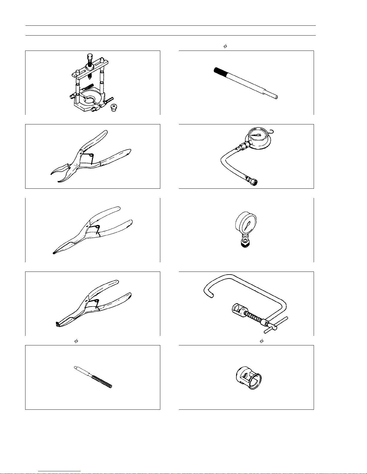
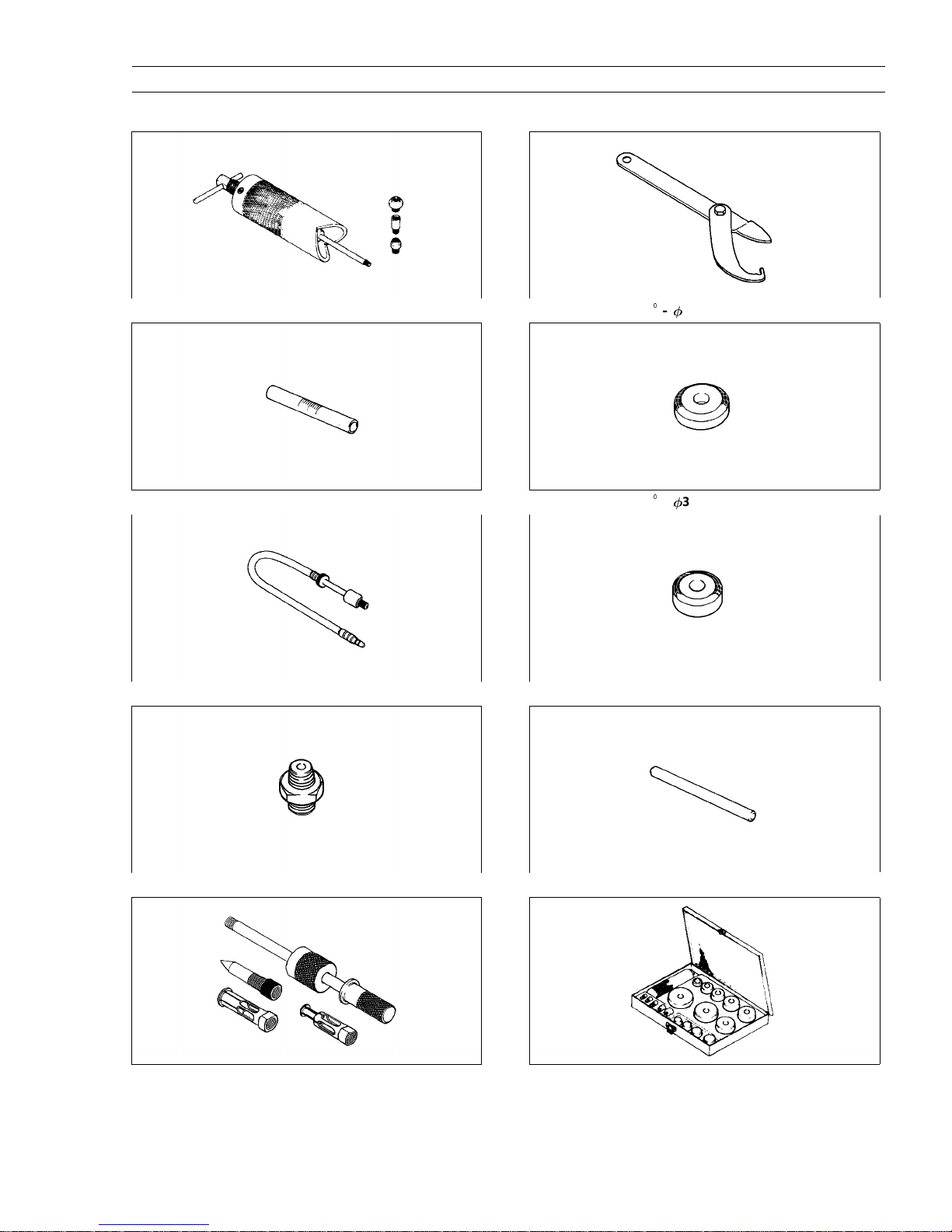
Special Tools and Sealant
Bearing Puller : 57001–135
Inside Circlip Pliers : 57001–143
Outside Circlip Pliers : 57001–144
Valve Guide Arbor,
Oil Pressure Gauge, 10 kg/cm
Compression Gauge : 57001–221
7 : 57001–163
2
: 57001–164
Circlip Pliers : 57001–154
Valve Guide Reamer, 7 : 57001–162
Valve Spring Compressor Assembly : 57001–241
Valve Spring Compressor Adapter, 28.2 : 57001–243
Special Tools and Sealant
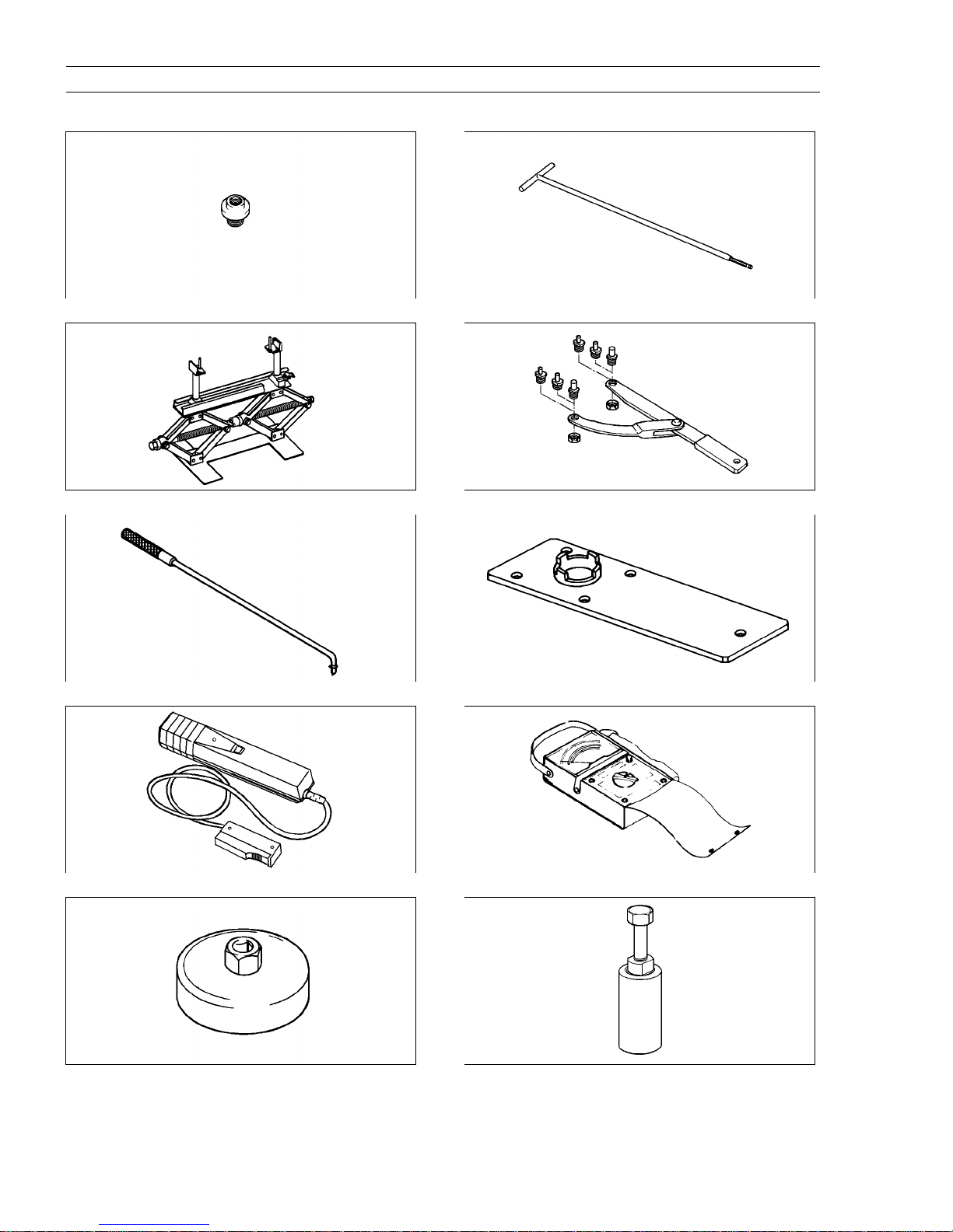
GENERAL INFORMATION 1-9
Piston Pin Puller Assembly : 57001–910
Fuel Level Gauge : 57001–1017
Compression Gauge Adapter, M12 x 1.25 : 57001–1018
Steering Stem Nut Wrench : 57001–1100
Valve Seat Cutter, 45
Valve Seat Cutter, 32– 38.5 : 57001–1122
41.5 : 57001–1117
–
Oil Pressure Gauge Adapter, PT 1/8 : 57001–1033
Oil Seal & Bearing Remover : 57001–1058
Valve Seat Cutter Holder Bar : 57001–1128
Bearing Driver Set : 57001–1129
1-10 GENERAL INFORMATION
Special Tools and Sealant
Piston Pin Puller Adapter : 57001–1211
Jack : 57001–1238
Pilot Screw Adjuster, A : 57001–1239
Carburetor Drain Plug Wrench, Hex 3 : 57001–1269
Flywheel & Pulley Holder : 57001–1343
Socket Wrench : 57001–1363
Timing Light : 57001–1241
Oil Filter Wrench : 57001–1249
Hand Tester : 57001–1394
Flywheel Puller Assembly : 57001–1405
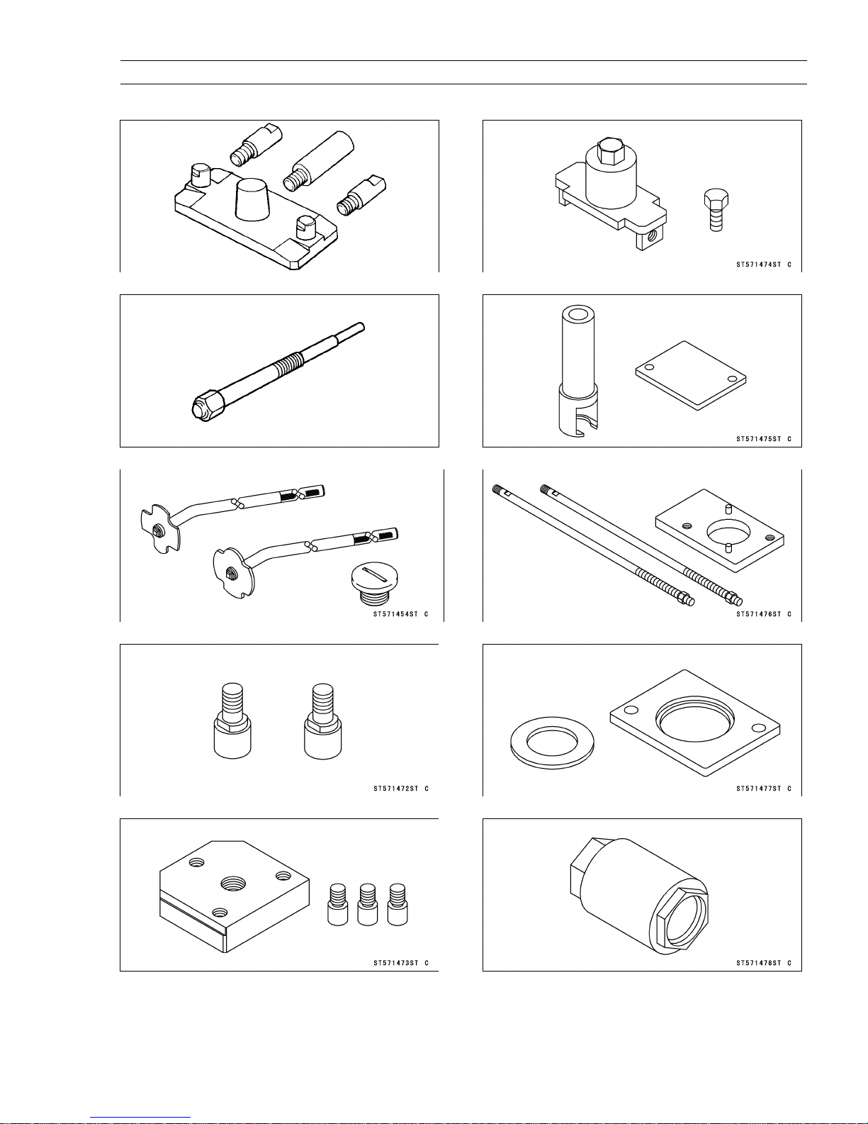
Special Tools and Sealant
GENERAL INFORMATION 1-11
Drive & Driven Pulley Holder : 57001–1412
Drive Pulley Puller Bolt : 57001–1429
Filler Cap Driver : 57001–1454
Drive Pulley Wrench : 57001–1474
Damper Spring Compressor Set : 57001–1475
Holder & Guide Arbor : 57001–1476
Pulley Holder Attachment : 57001–1472
Drive & Driven Pulley Holder : 57001–1473
Spacer & Holder : 57001–1477
Socket Wrench, Hex 50 : 57001–1478
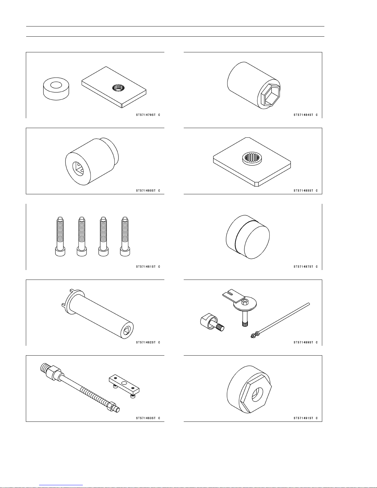
1-12 GENERAL INFORMATION
Special Tools and Sealant
Output Shaft Holder & Spacer : 57001–1479
Pinion Gear Holder : 57001–1480
Nut Holding Bolts : 57001–1481
Socket Wrench, Hex 41 : 57001–1484
Pinion Gear Holder : 57001–1485
Oil Seal Driver: 57001–1487
Socket Wench : 57001–1482
Spring Holder Set : 57001–1483
Gear Holder & Socket Wrench, Hex 24 : 57001–1489
Hexagon Wench, Hex 41 : 57001–1491
Special Tools and Sealant
GENERAL INFORMATION 1-13
Drive Pulley Measurement Tool : 57001–1498
Actuator Lever Measurement Tool : 57001–1499
Oil Seal Driver, 18: 57001–1505
Valve Seat Cutter, 50
Oil Seal Driver: 57001–1517
Belt Measuring Gauge: 57001–1519
44: 57001–1516
-
Oil Seal Driver, 48: 57001–1506
Valve Seat Cutter, 32- 44: 57001–1515
Drive Pulley Holder: 57001–1520
Kawasaki Bond (Silicone Sealant) : 56019–120
1-14 GENERAL INFORMATION
Unit Conversion Table
Prefixes for Units:
Prefix Symbol Power
mega M
kilo k
centi c
milli m
micro
2
2
2
2
2
Units of Mass:
kg
g
2
2
2.205 = lb
0.03527 = oz
Units of Volume:
L
L
L
L
L
L
mL
mL
mL
2
2
2
2
2
2
2
2
2
0.2642 = gal (US)
0.2200 = gal (imp)
1.057 = qt (US)
0.8799 = qt (imp)
2.113 = pint (US)
1.816 = pint (imp)
0.03381 = oz (US)
0.02816 = oz (imp)
0.06102 = cu in
Units of Force:
N
N
kg
kg
2
2
2
2
0.1020 = kg
0.2248 = lb
9.807 = N
2.205 = lb
1 000 000
1 000
0.01
0.001
0.000001
Units of Length:
km
m
mm
2
2
2
Units of Torque:
1
m
N
N
1
m
N
1
m
kg1m
kg
1
kg
1
m
m
2
2
2
2
2
2
Units of Pressure:
kPa
kPa
kPa
kg/cm
kg/cm
cm Hg
2
2
2
2
2
2
2
2
Units of Speed:
km/h
2
Units of Power:
kW
kW
PS
PS
2
2
2
2
0.6214 = mile
3.281 = ft
0.03937 = in
0.1020 = kg
0.7376 = ft
8.851 = in
9.807 = N
7.233 = ft
86.80 = in
0.01020 = kg/cm
0.1450 = psi
0.7501 = cmHg
98.07 = kPa
14.22 = psi
1.333 = kPa
0.6214 = mph
1.360 = PS
1.341 = HP
0.7355 = kW
0.9863 = HP
1
m
1
lb
1
lb
1
m
1
lb
1
lb
2
Units of Temperature:

PERIODIC MAINTENANCE 2-1
Periodic Maintenance
Table of Contents
Periodic Maintenance Chart.......................................2-2
Torque and Locking Agent.........................................2-3
Specifications.............................................................2-8
Periodic Maintenance Procedures...........................2-10
Fuel System..........................................................2-10
Throttle Lever Free Play Inspection..................2-10
Throttle Lever Free Play Adjustment.................2-10
Fuel System Cleanliness Inspection.................2-11
Air Cleaner Element Cleaning and Inspection..2-11
Air Cleaner Draining..........................................2-12
Fuel Hose and Connection Check....................2-12
Fuel Hose Replacement....................................2-12
Engine Top End....................................................2-13
Valve Clearance Inspection...............................2-13
Spark Arrester Cleaning....................................2-13
Converter System.................................................2-14
Actuator Lever (Engine Brake Control Lever) As-
sembly Inspection..............................................2-14
Drive Belt Inspection.........................................2-14
Drive Belt Deflection Inspection........................2-15
Drive Belt Deflection Adjustment.......................2-16
Engine Lubrication System...................................2-17
Engine Oil Change............................................2-17
Oil Filter Change...............................................2-17
Oil Cooler Cleaning and Inspection..................2-17
Oil Hose and Connection Check.......................2-18
Wheels/Tires.........................................................2-18
Tire Inspection...................................................2-18
Final Drive.............................................................2-19
Variable Differential Control Lever Position Inspec-
tion.....................................................................2-19
Variable Differential Control Lever Position Adjust-
ment...................................................................2-19
2
Front Final Gear Case Oil Change...................2-19
Rear Final Gear Case Oil Change....................2-20
Joint Boots Inspection.......................................2-20
Rear Propeller Shaft Joint Boot Inspection.......2-20
Brakes...................................................................2-21
Front Brake Pad Wear Inspection.....................2-21
Brake Hose and Connection Check..................2-21
Brake Hose Replacement.................................2-21
Brake Fluid Level Inspection.............................2-21
Brake Fluid Change...........................................2-22
Brake Master Cylinder Piston Assembly and Dust
Seal Replacement.............................................2-22
Caliper Piston Seal and Dust Seal Replacement2-23
Rear Brake Plates Replacement.......................2-23
Rear Brake Lever Free Play Inspection............2-23
Brake Pedal Free Play Inspection.....................2-23
Rear Brake Lever and Pedal Free Play Adjust-
ment...................................................................2-23
Steering.................................................................2-24
Steering Inspection............................................2-24
Electrical System..................................................2-24
Battery Inspection..............................................2-24
Spark Plug Cleaning / Inspection......................2-24
Spark Plug Gap Inspection...............................2-24
Drive Belt Failure Detection System Inspection2-24
Brake Light Switch Adjustment.........................2-24
General Lubrication...............................................2-26
Lubrication.........................................................2-26
Bolts and Nuts Tightening....................................2-27
Tightness Inspection..........................................2-27
2-2 PERIODIC MAINTENANCE
Periodic Maintenance Chart
The scheduled maintenance must be done in accordance with this chart to keep the vehicle in good running condition.
The initial maintenance is vitally important and must not be neglected.
FREQUENCY
OPERATION
ENGINE
Converter drive belt wear – inspect *
Converter drive belt deflection - inspect *
Drive belt failure detection system function – inspect*
Engine brake control lever – inspect*
Air cleaner – service*
Throttle lever play – inspect
Valve clearance – inspect
Fuel system cleanliness – inspect*
Engine oil – change *
Oil filter – replace*
Spark plug – clean and gap
Spark arrester – clean
Oil cooler– clean*
Oil hoses and connections – inspect*
Fuel hoses and connections – inspect
Fuel hose – replace 4 years
CHASSIS
Joint boots – inspect*
Rear brake pedal and lever adjustment – inspect*
Rear brake plates – change* every 10 000 km (6 000 mi.)
Cables adjustment*
Bolts and nuts – tighten
Front brake pad wear – inspect*
Brake light switch – inspect*
Battery – inspect
Steering – inspect
Differential control lever play– inspect
Tire wear – inspect*
Front and rear finial gear case oil – change
General lubrication*
Front brake fluid level – inspect
Front brake fluid – change
Brake master cylinder piston assembly and dust seal
– replace
Caliper piston seal and dust seal – replace 2 years
Brake hoses and connections– inspect
Brake hose – replace 4 years
*: Service more frequently when operated in mud, dust, or other harsh riding conditions, or when carrying heavy
loads or pulling a trailer.
: Clean, adjust, lubricate, torque, or replace parts as necessary.
•
When the drive belt failure detection system is activated, inspect the drive belt.
First
Service
After 10
hrs. or
100 km
(60 mi.)
of use
Every
10
days
or 200
km
(120
mi.) of
use
Regular Service
Every
30
days
or 600
km
(360
mi.) of
use
Every 90 days or
1700 km (1100 mi.)
of use, or when
BELT indicator light
comes on (100
hrs.) whichever
comes first
•
•
(NOTE)
•
•
• •
• •
• •
• •
• •
• •
• •
•
• •
• •
• •
• •
• •
• •
• •
• •
• •
•
• •
•
• •
2 years
•
NOTE
Every
year of
use
•
•
•
•
PERIODIC MAINTENANCE 2-3
Torque and Locking Agent
The following tables list the tightening torque for the major fasteners, and the parts requiring use of a non-permanent
locking agent or liquid gasket.
Letters used in the “Remarks” column mean:
L: Apply a non-permanent locking agent.
LB: Apply a non-permanet locking agent (Three Bond TB2471, Blue).
MO: Apply molybdenum disulfide oil solution (mixture of the engine oil and molybdenum disulfide grease in a weight
ratio 10:1).
EO: Apply engine oil.
M: Apply molybdenum disulfide grease.
SS: Apply silicone sealant (Kawasaki Bond: 56019-120).
Lh: Left-hand Threads
R: Replacement Parts
S: Follow the specific tightening sequence.
St: Stake the fasteners to prevent loosening.
Torque
Fastener N1m kgf1m ft1lb Remarks
Fuel System:
Throttle Cable Locknut 1.3 0.13 11 in1lb
Air Cleaner Duct Front Clamp Screw 1.4 0.14 12 in1lb
Air Cleaner Duct Rear Clamp Screw 4 0.41 36 in
Air Cleaner Housing Mounting Bolts 6.9 0.7 61 in
Air Cleaner Intake Duct Clamp Screws 1.4 0.14 12 in1lb
Engine Top End:
Camshaft Chain Tensioner Mounting Bolts 8.8 0.9 78 in
Camshaft Sprocket Bolts 14 1.4 10 L
Camshaft Cover Bolts 8.8 0.9 78 in
Bearing Retainer Bolts 12 1.2 104 in
Camshaft Chain Guard Bolts 8.8 0.9 78 in
Rear Camshaft Chain Guide Bolt 9.8 1.0 87 in
Cylinder Head Bolts (M11), first torque 25 2.5 18 MO, S
Cylinder Head Bolts (M11), final torque 44 4.5 33 S
Cylinder Head Bolts (M6) 12 1.2 104 in
Valve Adjusting Screw Locknuts 12 1.2 104 in1lb
Valve Adjusting Cap Bolts 8.8 0.9 78 in
Muffler Mounting Bolts 26 2.7 20
Converter System:
Converter Cover Bolts 8.8 0.9 78 in1lb S
Driven Pulley Nut 93 9.5 69
Ramp Weight Nuts 6.9 0.7 61 in1lb
Spider 275 28 203 Lh
Drive Pulley Cover Bolts 13 1.3 113 in1lb
Drive Pulley Bolt 93 9.5 69 R, Lh
Converter Air Duct Bolts 8.8 0.9 78 in1lb
Recoil Starter:
Recoil Starter Mounting Bolts 5.9 0.6 52 in1lb L
Engine Lubrication System:
Engine Drain Plug 20 2.0 14
Oil Filter 18 1.8 13 R
Oil Pressure Switch 15 1.5 11 SS
Oil Pressure Relief Valve 15 1.5 11 L
Oil Pump Cover Bolt 20 2.0 14
Oil Pump Cover Screws 5.4 0.55 48 in1lb
Oil Pipe Bolts 8.8 0.9 78 in1lb
1
lb
1
lb
1
lb
1
lb
1
lb
1
lb
1
lb
1
lb
1
lb
S
2-4 PERIODIC MAINTENANCE
Torque and Locking Agent
Torque
Fastener N1m kgf1m ft1lb Remarks
Oil Pipe Joint Nuts
Oil Cooler Mounting Bolts 8.8 0.9 78 in1lb
Oil Cooler Fan Switch 16 1.6 12
Oil Temperature Warning Light Switch 16 1.6 12
Oil Filter Mounting Bolt 25 2.5 18 L
Oil Hose Banjo Bolts 29 3.0 22
Oil Pressure Switch Terminal Bolt 1.5 0.15 13 in1lb
Engine Removal/Installation
Engine Mounting Bracket Bolts 25 2.5 18
Engine Mounting Nuts 42 4.3 31
Engine Mounting Upper Bolt 25 2.5 18
Crankshaft/Transmission:
Crankcase Bolts (M8) 20 2.0 14 S, L (1)
Crankcase Bolts (M6) 8.8 0.9 78 in
Shift Shaft Positioning Bolt 25 2.5 18
Tie-Rod End Locknut 20 2.0 14
Tie-Rod End Bolt 9.8 1.0 87 in1lb
Shift Lever Assembly Nut 20 2.0 14
Tie-Rod End Nut 20 2.0 14
Shift Lever Assembly Bracket Bolts 20 2.0 14
Tie-Rod End Rear Locknut 9.8 1.0 87 in
Tie-Rod End Front Locknut 9.8 1.0 87 in
Grip Hold Nut 9.8 1.0 87 in
Shift Shaft Spring Bolt 25 2.5 18 L
Shift Shaft Cover Bolts 8.8 0.9 78 in
Oil Line Plugs 23 2.3 17 L
Wheels/Tires:
Tie-Rod Adjusting Sleeve Locknuts 37 3.8 27
Wheel Nuts 52 5.3 38
Front Axle Nuts 196 20 145
Rear Axle Nuts 265 27 195
Final Drive:
(Output Bevel Gears)
Output Drive Bevel Gear Housing Bolts 26 2.7 20
Rotor Mounting Bolts 12 1.2 104 in1lb
Output Drive Bevel Gear Cover Bolts 8.8 0.9 78 in1lb
Forward/Reverse Detecting Sensor Mounting Bolts 15 1.5 11
Bearing Holder 118 12 87 L
Bevel Gear Holder Nut 157 16 116 L
Output Drive Bevel Gear Housing Bolts 26 2.7 20
Bearing Holder 137 14 101 L
Output Shaft Holder Nut 157 16 116 L
(Front Final Gear Case)
Oil Filler Cap 29 3.0 22
Oil Drain Plug 24 2.4 17
Variable Differential Control Cable Locknut 17 1.7 12
Front Final Gear Case Bolts and Nuts 42 4.3 31
Front Final Gear Case Center Cover Bolts (M8) 24 2.4 17 L, S
Front Final Gear Case Center Cover Bolts (M6) 9.8 1.0 87 in1lb L, S
Pinion Gear Bearing Holder 137 14 101 L
Front Final Gear Case Left Cover Bolts (M6) 9.8 1.0 87 in1lb S, L (4)
29 3.0 22
1
lb
1
lb
1
lb
1
lb
1
lb
Lh
PERIODIC MAINTENANCE 2-5
Torque and Locking Agent
Torque
Fastener N1m kgf1m ft1lb Remarks
Front Final Gear Case Coupling Nut
Variable Front Differential Control Shift Shaft Lever 8.8 0.9 78 in1lb
Ring Gear Bolts 57 5.8 42 LB
Pinion Gear Bearing Holder Nut 127 13 94 St
(Rear Axle)
Bearing Holder 255 26 188 M
Bearing Holder Screws 16 1.6 12 L
(Rear Final Gear Case)
Oil Filler Cap 29 3.0 22
Oil Drain Plug 20 2.0 14
Rear Final Gear Case Bolts 42 4.3 31 S
Pinion Gear Bearing Holder 137 14 101 L
Rear Final Gear Case Right Cover Bolts (M10) 49 5.0 36 L
Rear Final Gear Case Right Cover Bolts (M8) 24 2.4 17 L
Pinion Gear Bearing Holder Nut 157 16 116 L
Brakes:
Reservoir Cap Screws 1.5 0.15 13 in1lb
Bleed Valves 5.9 0.6 52 in
Master Cylinder Clamp Bolts 8.8 0.9 78 in
Brake Hose Banjo Bolts 25 2.5 18
Brake Lever Pivot Bolt 5.9 0.6 52 in
Brake Lever Pivot Bolt Locknut 5.9 0.6 52 in
Caliper Mounting Bolts 25 2.5 18
Caliper Holder Shaft 18 1.8 13
Caliper Holder Shaft (Allen Bolt) 23 2.3 17
Pad Mounting Bolts 18 1.8 13
Disc Mounting Bolts 37 3.8 27 L
Suspension:
Front Shock Absorber Clamp Bolts and Nuts 47 4.8 35
Front Shock Absorber Mounting Nuts 74 7.5 54
Rear Shock Absorber Mounting Nuts 62 6.3 46
Piston Rod Nut 49 5.0 36
Suspension Arm Pivot Bolts 88 9.0 65
Swingarm Pivot Right Shaft 152 15.5 112 L
Swingarm Pivot Left Shaft 20 2.0 14
Swingarm Pivot Left Nut 152 15.5 112
Steering:
Steering Stem Bottom End Nut 62 6.3 46
Steering Stem Clamp Bolts 25 2.5 18
Tie-Rod End Nuts 42 4.3 31
Steering Knuckle Joint Nuts 47 4.8 35
Front Shock Absorber Clamp Bolts and Nuts 47 4.8 35
Tie-Rod Adjusting Sleeve Locknuts 37 3.8 27
Handlebar Lower Holder Nuts 37 3.8 27 L
Handlebar Holder Bolts 27 2.8 20 S
Frame:
Rear Carrier Bolts and Nuts 25 2.5 18
Front Carrier Bolts – – –
Front Guard Bolts 20 2.0 14
Trailer Hitch Bracket Bolts (M10) 49 5.0 36 L
Trailer Hitch Bracket Bolts (M8) 24 2.4 17 L
20 2.0 14
1
lb
1
lb
1
lb
1
lb
L
2-6 PERIODIC MAINTENANCE
Torque and Locking Agent
Torque
Fastener N1m kgf1m ft1lb Remarks
Footboard Mounting Nuts
Electrical System:
Alternator Cover Bolts 8.8 0.9 78 in
Alternator Rotor Bolts 127 13 94
Alternator Stator Bolts 14 1.4 10
Spark Plug 14 1.4 10
Ignition Coil Mounting Bolt 8.8 0.9 78 in1lb
Pickup Coil Mounting Bolts 5.9 0.6 52 in1lb
Starter Motor Mounting Bolts 8.8 0.9 78 in
Starter Motor Terminal Nut 4.9 0.5 43 in1lb
Starter Motor Terminal Locknut 6.9 0.7 61 in
Starter Motor Bolts 3.4 0.3 30 in
Starter Motor Clutch Bolts 34 3.5 25 L
2WD/4WD Actuator Mounting Bolts 9.8 1.0 87 in
Engine Brake Actuator Mounting Bolts 8.8 0.9 78 in
Reverse Position Switch 15 1.5 11
Neutral Switch 15 1.5 11
Starter Relay Terminal Nuts 4.9 0.5 43 in
Igniter Mounting Bolts 2.3 0.23 20 in
Ignition Switch Nut 2.7 0.28 24 in
Oil Pressure Switch Terminal Bolt 1.5 0.15 13 in
Regulator/Rectifier Mounting Bolts 8.8 0.9 78 in
– – – L
1
lb
1
lb
1
lb
1
lb
1
lb
1
lb
1
lb
1
lb
1
lb
1
lb
1
lb
L, S
PERIODIC MAINTENANCE 2-7
Torque and Locking Agent
The tables below, relating tightening torque to thread diameter, lists the basic torque for the bolts and nuts. Use this
table for only the bolts and nuts which do not require a specific torque value. All of the values are for use with dry
solvent-cleaned threads.
Basic Torque for General Fasteners of Engine Parts
Threads dia. Mark of Torque
1
mm (in.) bolt head N
6 (0.24) 9T 12
6 (0.24) 7T 7.8
6 (0.24) 4T 3.9
8 (0.31) 7T 18
8 (0.31) 4T 10
10 (0.39) 7T 39 44 4.0 4.5 29 33
10 (0.39) 4T 20
5 (0.20) 4T 2.2
Basic Torque for General Fasteners of Frame Parts
Threads dia. Torque
mm (in.) N1m kgf1m ft1lb
5 (0.20) 3.4 4.9 0.35 0.5 30 43 in1lb
6 (0.24) 5.9 7.8 0.6 0.8 52 69 in1lb
8 (0.31) 14 19 1.4 1.9 10.0 13.5
10 (0.39) 25 34 2.6 3.5 19.0 25
12 (0.47) 44 61 4.5 6.2 33 45
14 (0.55) 73 98 7.4 10.0 54 72
16 (0.63) 115 155 11.5 16.0 83 115
18 (0.71) 165 225 17.0 23.0 125 165
20 (0.79) 225 325 23 33 165 240
m
15
9.8
4.9
22
14
24
2.6
kgf1m ft1lb
1.5
1.2
0.8
0.4
1.8
1.0
2.0
0.22
1.0
0.5
2.2
1.4
2.4
0.27
104
87
69
35
19
13
14
130 in
87 in
43 in
16
122 in
17
23 in
1
lb
1
lb
1
lb
1
lb
1
lb

2-8 PERIODIC MAINTENANCE
Specifications
Item
Fuel System:
Throttle lever free play 2 ~ 3 mm (0.08 ~ 0.12 in.) –––
Air cleaner element oil High-quality foam air filter oil –––
Engine Top End:
Valve clearance:
Exhaust 0.15 ~ 0.20 mm (0.0059 ~ 0.0079 in.) –––
Inlet 0.08 ~ 0.13 mm (0.0032 ~ 0.0051 in.) –––
Converter System:
Actuator lever guide shoe wear ––– 6 mm (0.24 in.)
Belt width 29.8 ~ 31.0 mm (1.17 ~ 1.22 in.) 29.4 mm (1.16 in.)
Belt deflection 20 ~ 27 mm (0.79 ~ 1.06 in.) –––
Engine Lubrication System:
Engine oil:
Type API SF or SG –––
API SH or SJ with JASO MA –––
Viscosity SAE10W40 –––
Capacity 1.50 L (1.59 US qt) (When filter is not removed) –––
1.74 L (1.84 US qt) (When filter is removed) –––
2.3 L (2.43 US qt) (When engine is completely dry) –––
Wheels/Tires
Tire tread depth:
Front ––– 3 mm (0.12 in.)
Rear ––– 4 mm (0.16 in.)
Standard tire:
Front AT 25 X 8-12 –––
Dunlop, KT121, Tubeless –––
Rear AT 25 x 10-12 –––
Dunlop, KT405C/KT127A, Tubeless –––
Final Drive:
Front Final Gear Case:
Gear Case Oil:
Type API SF or SG –––
API SH or SJ of JASO MA –––
Viscosity SAE 10W-40 –––
Oil level Filler opening bottom –––
Capacity 430 mL (0.45 US qt) –––
Rear Final Gear Case:
Gear Case Oil:
Type MOBIL Fluid 424 or Kawa Chem Gear & Wet Brake Oil –––
(CITGO TRANSGARD TRACTOR HYDRAULIC FLUID)
Oil level Filler opening bottom –––
Capacity 900 mL (0.95 US qt) –––
Brakes:
Front Brake Fluid:
Type DOT 3 or DOT 4 –––
Front Disc Brake:
Pad lining thickness 4.5 mm (0.18 in.) 1 mm (0.04 in.)
Rear Brake Lever, Pedal
and Cables:
Rear brake lever free play 1 ~ 2 mm (0.04 ~ 0.08 in.) –––
Brake pedal free play 15 ~ 25 mm (0.6 ~ 1.0 in.) –––
Electrical System:
Spark plug gap 0.8 ~ 0.9 mm (0.031 ~ 0.035 in.) –––
Rear brake light switch timing On after 10 mm (0.4 in.) of pedal travel –––
Standard Service Limit

Specifications
Special Tools - Carburetor Drain Plug Wrench, Hex 3: 57001–1269
Belt Measuring Gauge: 57001–1519
Flywheel & Pulley Holder: 57001–1343
Pulley Holder Attachment: 57001–1472
Oil Filter Wrench: 57001–1249
PERIODIC MAINTENANCE 2-9
2-10 PERIODIC MAINTENANCE
Periodic Maintenance Procedures
Fuel System
Throttle Lever Free Play Inspection
Check that the throttle lever moves smoothly from full open to close,
•
and the throttle closes quickly and completely in all steering positions
by the return spring.
If the throttle lever does not return properly, check the throttle cable
routing, lever free play, andfor possible cable damage. Then lubricate
the throttle cable.
Run the engine at the idle speed, and turn the handlebar all the way
•
to the right and left to ensure that the idle speed does not change.
If the idle speed increases, check the throttle lever free play and the
cable routing.
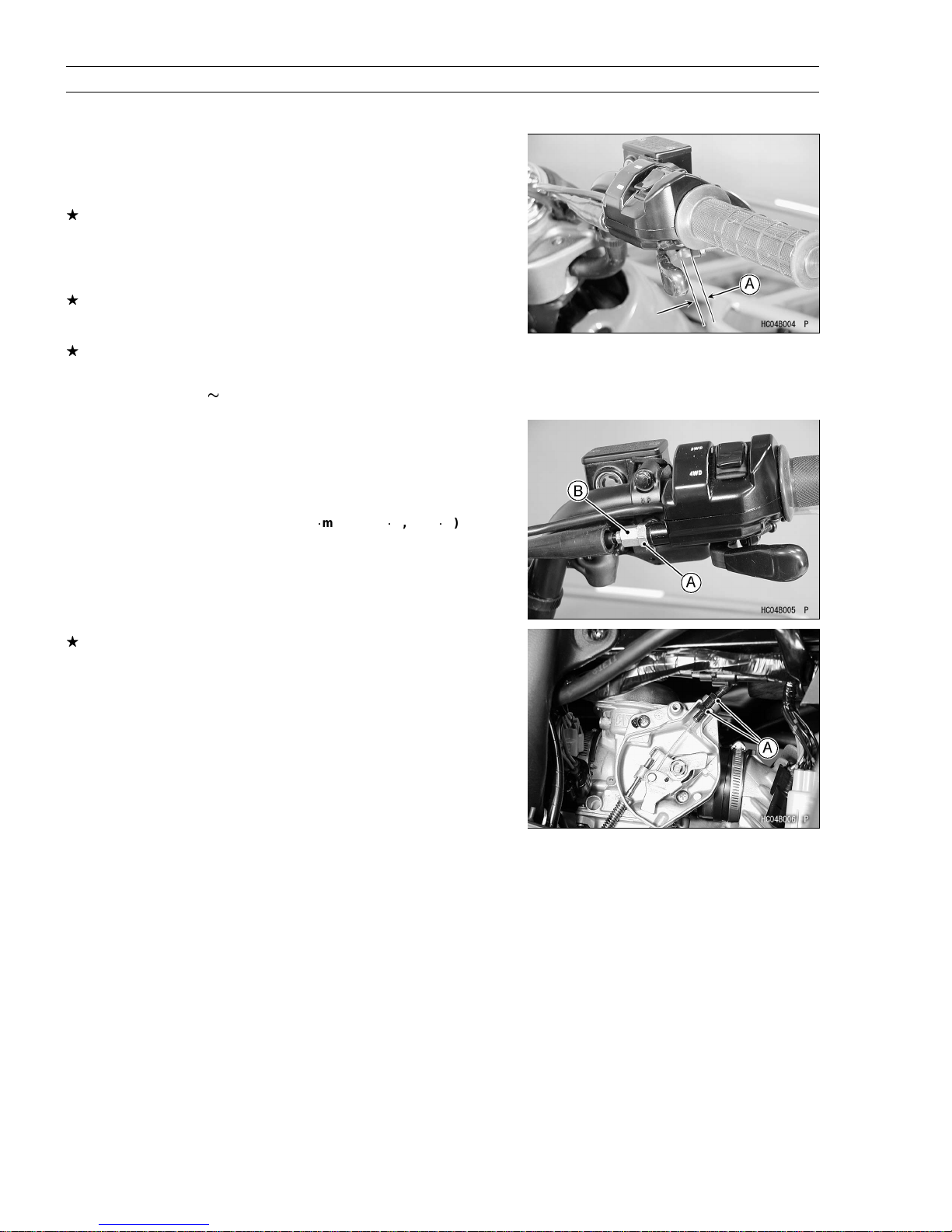
Stop the engine and check the throttle lever free play [A].
•
If the free play is not within the specified range, adjust the cable.
Throttle Lever Free Play
Standard: 2
Throttle Lever Free Play Adjustment
Slide the rubber cover off the adjuster at the throttle case.
•
Loosen the locknut [A] and turn the throttle cable upper adjuster [B]
•
until the cable has proper amount of play.
Tighten the locknut and reinstall the rubber cover.
•
Torque - Throttle Cable Locknut: 13 N
3 mm (0.08 ~ 0.12 in.)
1
m (0.13 kgf1m, 11 in
1
lb)
If the free play cannot be adjusted by using the upper cable adjuster,
removethe throttle cable pulley cover and then use the cableadjusting
nuts [A] at the lower end of the throttle cable and make the necessary
free play.
 Loading...