

Quick Reference Guide
This Quick Reference Guide will
assist you in finding the information
you’re looking for.
A Table of Contents is included after
the Foreword.
SAFETY INFORMATION j
GENERAL INFORMATION j
HOW TO RIDE THE MOTORCYCLE j
MAINTENANCE AND ADJUSTMENT j
APPENDIX j
MAINTENANCE RECORD j
Whenever you see the symbols
shown below, heed their instructions!
Always follow safe operating and maintenance practices.
DANGER
DANGER indicates a hazardous
situation which, if not avoided,
will result in death or serious in-
jury.
WARNING
WARNING indicates a hazardous
situation which, if not avoided,
could result in death or serious
injury.
NOTICE
NOTICE is used to address prac-
tices not related to personal in-
jury.
NOTE
NOTE indicates information that may
○
help or guide you in the operation or
service of the vehicle.
WARNING
Engine exhaust, some of its
constituents, and certain vehicle components contain or emit
chemicals known to the State of
California to cause cancer and
birth defects or other reproductive harm .
NOTICE
THIS PRODUCT HAS BEEN
MANUFACTURED FOR USE IN A
REASONABLE AND PRUDENT
MANNER BY A QUALIFIED OPERATOR AND AS A VEHICLE
ONLY.

Foreword
Congratulations on your purchase of a new Kawasaki motorcycle. Your new motorcycle is the product of Kawasaki’s advanced engineering, exhaustive testing,
and continuous striving for superior reliability, safety and p e rfo rmance.
Please read this Owner ’s Manual carefully before riding so that you will be
thoroughly familiar with the proper operation of your motorcycle’s controls, its features, capabilities, and limitations. This manual offers many safe riding tips, but its
purpose is n ot to provide instruction in all the techniques and skills required to ride
a motorcycle safely. Kawasaki strongly recommends that all operators of this vehicle enroll in a motorcycle rider training program to attain awareness of the mental
and physical requirements necessary for safe motorcycle operation.
To ensure a long, trouble-free life for your motorcycle, give it the proper care and
maintenance described in this manual. For those who would like more detailed information on their Kawasaki Motorcycle, a Service Manual is available for purchase
from any authorized Kawasaki motorcycle dealer. The Service Manual contains detailed disassembly and maintenance information. Those who plan to do their own
work should, of course, be competent mechanics and possess the special tools
described in the Service Manual.
Keep this Owner’s Manual aboard your motorcycle at all times so that you can
refer to it whenever you need information.

This manual should be considered a permanent part of the motorcycle and should
remain with the motorcycle when it is sold.
All rights reserved. No part of this publication may be reproduced without our
prior written permission.
This publication includes the latest information available at the time of printing.
However, there may be minor differences be twee n the actual product and illustrations and text in this manual.
All products are subject to change without prior notice or obligation.
KAWASAKI HEAVY INDUSTRIES, LTD.
Motorcycle & Engine Company
© 2013 Kawasaki H eavy Industries, Ltd. May 17, 2013. (1)

Emission Control Information
To protect the environment in which we all live, Kawasaki has incorporated
crankcase emission (1) and exhaust emission (2) control systems in compliance
with applicable regulations of the U nited States Environmental Protection Agency
and California Air Resources Board. Additionally, K awasaki has incorporated
an evaporative emission control system (3) in compliance with applicable regulations of the United States Environmental Protection Agency and California Air
Resources Board.
1. Crankcase Emission Control System
This system eliminates the release of crankcase vapors into the atmosphere.
Instead, the vapors are routed through an oil separator to the intake side of the
engine. While the engine is operating, the vapors are drawn into the combustion
chamber, where they are burned along with the fuel and air supplied by the fuel
injection system.
2. Exhaust Emission Control System
This system reduces the amount of pollutants discharged into the atmosphere
by the exhaust of this motorcycle. The fuel, ignition and exhaust systems of this
motorcycle have been carefully designed and constructed to ensure an efficient
engine with low exhaust pollutant levels. The exhaust system of this model motorcycle includes a catalytic converter system.

3. Evaporative Emission Control System
The evaporative emission control system for this vehicle consists of low perme-
ation fuel hoses and fuel tank.
3. Evaporative Emission Control System (California)
Vapors caused by fuel evaporation in the fuel system are not vented into the
atmosphere. Instead, fuel vapors are routed into the running engine to be burned,
or stored in a canister when the engine is stopped.
High Altitude Performance Adjustment Information
High Altitude adjustment is not required.

Maintenance and Warranty
Proper maintenance is necessary to ensure that your motorcycle will continue to
have low emission levels. This Owner ’s Manual contains those maintenance recommendations for your motorcycle. Those items identified by the Periodic Maintenance Chart are necessary to ensure compliance with the applicable standards.
As the owner of this motorcycle, you have the responsibility to make sure that
the recommended maintenance is carried out according to the instructions in this
Owner’s Manual at your own expense.
The Kawasaki Limited Emission Control System Warranty requires that you return your motorcycle to an authorized Kawasaki dealer for remedy under warranty.
Please rea d the warranty carefully, and keep it valid by complying with the owner’s
obligations it contains.
You should keep a maintenance record for your motorcycle. To assist you in
keeping this record, we have provided space on pages 180 through 185 of this
manual where an authorized Kawasaki dealer, or someone equally competent, can
record the maintenance. You should also retain copies of maintenance work orders,
bills, etc., as verification of this maintenance.

Tampering With Noise Control System Prohibited
Federal law prohibits the following acts or the causing thereof: (1) the removal or
rendering inoperative by any person other than for purposes of maintenance, repair, or replacement, of any device or element of design incorporated into any new
vehicle for the purpose of noise control prior to its sale or delivery to the ultimate
purchaser or while it is in use, or (2) the use of the vehicle after such device o r
element of design has been removed or rendered inoperative by any person.
Among those acts presumed to constitute tampering are the acts listed below:
* Replacement of the original exhaust system or muffler with a component not in
compliance with Federal regulations.
* Removal of the muffler(s) or any internal portion of the muffler(s).
* Removal of the air box or air box cover.
* Modifications to the muffler(s) or air intake system by cuttin g, drilling, or oth er
means if such modifications result in in crea sed noise levels.

TABLE OF CONTENTS
SAFETY INFORMATION .................... 13
Read Owner’s Manual ..................... 13
Training ............................................ 13
Daily Checks and Periodic
Maintenance ................................. 13
Loading and Accessories
Information.................................... 14
Passenger .................................... 15
Baggage and Luggage ................. 16
Accessories .................................. 16
Other Load.................................... 17
If You are Involved in an Accident .... 17
Safe Operation ................................. 18
Carbon Monoxide Hazard............. 18
Fueling.......................................... 19
Never Ride with Drugs or Alcohol . 19
Protective Gear and Clothing ....... 19
Safe Riding Techniques................ 20
Additional Co nsiderations for High
Speed Operation ....................... 22
GENERAL INFORMATION................. 24
Specifications................................... 24
Serial Number Locations.................. 28
Location of Labels ............................ 29
Location of Parts .............................. 38
Meter Instruments ............................ 41
Tachometer................................... 43
Multifunction Meter ....................... 44
Indicator Lights ............................. 54
Warning Indicator Lights ............... 61
Keys ................................................. 65
Ignition Switch/Steering Lock ........... 66
Right Handlebar Switches ................ 68
Left Handlebar Switches .................. 69
Brake Lever Adjuster........................ 70
Fuel Tank Cap .................................. 70
Fuel Tank ......................................... 71
Side Stand ....................................... 76
Seat.................................................. 77
Helmet Hooks................................... 81

Tool Kit ............................................. 81
Air Cleaner Intake ............................ 82
Event Data Recorder........................ 82
HOW TO RIDE THE MOTORCYCLE .84
Break-In ........................................... 84
Starting the Engine .......................... 85
Jump Starting ................................... 88
Moving Off........................................ 90
Shifting Gears .................................. 91
Braking............................................. 93
Kawasaki Intelligent anti-lock
Brake System (KIBS, For models
equipped with KIBS) ..................... 94
Stopping the Engine......................... 96
Stopping the Motorcycle in an
Emergency ................................... 97
Parking............................................. 98
Kawasaki TRaction Control (KTRC). 99
Power Mode ..................................... 103
KTRC and Power Mode
Combination ................................. 104
MAINTENANCE AND ADJUSTMENT 106
Daily Checks .................................... 108
Periodic Maintenance....................... 111
Engine Oil ........................................ 116
Coolant............................................. 119
Air Cleaner ....................................... 122
Throttle Control System ................... 126
Idle Speed ........................................ 128
Clutch............................................... 129
Drive Chain ...................................... 131
Brakes.............................................. 135
Brake Light Switches........................ 138
Suspension System ......................... 139
Front Fork ..................................... 139
Rear Shock Absorber ................... 142
Setting Tables............................... 1 45
Wheels ............................................. 148
Battery.............................................. 151
Headlight.......................................... 155
Fuses ............................................... 157
General Lubrication.......................... 158
Cleaning Your Motorcycle ................ 1 60
General Precautions ..................... 160
Washing Your Motorcycle ............. 161
APPENDIX .......................................... 166

Storage ............................................ 166
Troubleshooting Guide..................... 169
Your Warranty/Owner Satisfaction ... 170
Reporting Safety Defects ................. 176
Environmental Protection ................. 177
MAINTENANCE RECORD ................. 178
SAFETY INFORMATIO N
SAFETY INFORM ATION 13
Read Owner’s Manual
Read this Owner’s Manual carefully before riding so that you will be
thoroughly familiar with the proper operation of your motorcycle’s controls,
its fe atures , capabilities, and limitations. This manual offers many safe
riding tips, but its purpose is not to provide instruction in all of the techniques
and skills required to ride a motorcycle
safely.
Training
Kawasaki strongly recommends that
all operators of this vehicle complete a
suitable motorcycle rider training program to learn the proper skills and techniques necessary for safe m otorcycle
operation.
Daily Checks and Periodic Maintenance
It is important to keep your motorcycle properly maintained and in safe riding condition. Inspect your motorcycle before every ride and carry out all
periodic maintenance. See the Daily
Checks section and the Periodic Maintenance section in the MAINTENANCE
AND ADJUSTMENT chapter for more
information.
WARNING
Failure to perform these checks
or to correct a problem before
operation may result in serious
damage or an accident. Alwa ys
perform daily checks before op-
eration.
14 SAFETY INFORMATION
To ensure your motorcycle is serviced using the latest servicing information, it is recommended that an
authorized Kawasaki Dealer performs
the periodic maintenance as directed
in the Owner’s Manual.
If you notice any irregular operating condition, have your motorcycle
thoroughly checked at an authorized
Kawasaki dealer as soon as possible.
Loading and Accessories Information
WARNING
Incorrect loading, improper installation or use of accessories
or modification of your motorcycle may result in an unsafe riding
condition. B efore you ride the
motorcycle, make sure it is not
overloaded and that you have
followed these in structions.
Maximum L oad
Weight of rider, passenger, baggage,
and accessories must not exceed 180 kg
(397 lb).
With the exception of genuine
Kawasaki Parts and Accessories,
Kawasaki has no control over the
design or application of accessories.
In some cases, improper installation

SAFETY INFORM ATION 15
or use of accessories, or motorcycle
modification, will void the motorcycle
warranty; can negatively affect performance, stability and safety; and can
even be illegal.
In selecting and using accessories,
and in loading the motorcycle, you are
personally responsible for your own
safety and the safety of othe r persons
involved.
NOTE
Kawasaki Parts and Accessories
○
have been specially designed for
use on Kawasaki motorcycles. We
strongly recommend that all parts
and a ccessories you add to your
motorcycle be genuine Kawasaki
components.
Because a moto rcyc le is sensitive to
changes in weight and aerodynamic
forces, you must take extreme care in
carrying cargo, passengers and/or in
fitting additional accessories. The following general guidelines have been
prepared to assist you in m aking your
determinations.
Passenger
1. Never carry more than one passenger.
2. The passenger should only sit on the
pillion.
3. Any passenger should be thoroughly familiar with motorcycle operation. The passenger can affect
control of the motorcycle by improper positioning during cornering
and sudden movements. It is important that the passenger sits still
while the motorcycle is in motion
and not interfere with the operation
of the motorcycle. Do not carry animals on your motorcycle.
16 SAFETY INFORMATION
4. Do not carry passengers unless
passenger footpegs are installed.
Instruct any passenger before riding
to keep his or her feet on the passenger footpegs and hold on to the
operator or seat strap. Do not carry
a passenger unless he or she is tall
enough to reach the footpegs with
their feet.
Baggage and Luggage
1. All baggage should be carried as
low as possible to reduce the effect
on the motorcycle’s center of gravity. Baggage weight should also be
distributed equally on both sides of
the motorcycle. Avoid carrying baggage that extends beyond the rear
of the motorcycle.
2. Baggage should be securely attached. Make sure that the baggage
will not move around while you are
riding. Recheck baggage security
as often as possible (not while the
motorcycle is in motion) and adjust
as necessary.
3. Do not carry heavy or bulky items
on a luggage rack. It is designed
for light items, and overloading can
affect handling due to changes in
weight distribution and aerodynamic
forces.
Accessories
1. Do not install accessories or carry
baggage that impairs the performance of the motorcycle. Make
sure that you have not adversely
affected any lighting components,
road clearance, banking capability
(i.e., lean angle), control operation,
wheel travel, front fork movement,

SAFETY INFORM ATION 17
or any other aspects of the motorcycle’s operation.
2. Weight attached to the handlebar or
front fork will increase the mass of
the s teering assembly and can result in an unsafe riding condition.
3. Fairings, windshields, backrests,
and other large items have the capability of adversely affecting stability and handling of t he motorcycle,
not only due to their weight, but
also due to the aerodynamic force
acting on these surfaces while the
motorcycle is in operation. Poorly
designed or installed items can result in an unsafe riding condition.
Other Load
1. This motorcycle is not intended to
be equipped with a sidecar or to be
used to tow any trailers or other vehicles. Kawasaki does not manufacture sidecars or trailers for motorcycles and cannot predict the effects of such accessories on handling or stability, but can only warn
thattheeffectscanbeadverseand
that Kawasaki cannot assume responsibility for the results of such
unintended use of the motorcycle.
2. Furthermore, any adverse effects on
motorcycle components caused by
the use of such accessories will not
be remedied under warranty.
If You are Involved in an Accident
Make sure of your own safety first.
Determine the severity of any injuries
and call for emergency assistance if
needed. Always follow applicable laws
18 SAFETY INFORMATION
and regulations if any other person, vehicle or property is involved.
Do not attempt to continue riding
without first evaluating your motorcycle’s condition. Inspect for fluid leaks,
check critical nuts and bolts, and check
the handlebars, control levers, brakes,
and wheels for damage and proper
function. Ride slowly and cautiously
- your motorcycle may have suffered
damage that is not immediately apparent. Have your motorcycle thoroughly
checked at a Kawasaki dealer as soon
as possible.
Safe Operation
The following should be carefully observed for safe and effective vehicle
operation.
Carbon Monoxide Hazard
DANGER
Exhaust gas contains carbon
monoxide, a colorless, odorless
poisonous gas. Inhaling carbon
monoxide can cause serious
brain injury or death.
Do not run the engine in enclosed areas. Operate only in a
well-ventilated area.
SAFETY INFORM ATION 19
Fueling
WARNING
Gasoline is extreme ly flammable
and can be explosive under certain conditions.
To avoid a possible fire or explosion, turn the ignition switch to
“OFF.” Do not smoke. Make sure
theareaiswellventilatedand
free from any source of flame or
sparks; this includes any appliance with a pilot light.
Never Ride with Drugs or Alcohol
Alcohol and drugs impair your judgment and reaction time. Never consume alcohol or drugs before or while
riding motorcycles.
Protective Gear and Clothing
Helmet
Kawasaki strongly recommends both
the operator and passenger wear a
DOT-approved helmet even if this is
not a legal requirement.
- Make sure that your helmet fits cor-
rectly and is p roperly fastened.
- Choose a motorcycle helmet that
meets DOT safety standards. Ask
your motorcycle dealer to advise
you if necessary.

20 SAFETY INFORMATION
Eye Protection
Always use eye protection. If your
helmet does not have a visor installed,
wear goggles.
Gloves
Wear gloves which have suitable
protection for your hands, especially
against abrasion .
Clothing
Wear protective clothing.
- Wear bright, highly visible clothing
that allows freedom of movement
to suit your riding style.
- Always wear a long- s lee ve d jacket
and long trousers which are abrasion resistant and keep you warm.
- Avoid wearing clothes which have
loose cuffs or other fastenings
which could interfere with the controls of your motorcycle.
Boots
Wear proper protective boots that fit
properly and do not interfere with gear
shifting or braking.
Safe Riding Techniques
Keep Hands on Handlebars
When riding always keep both hands
on the handlebars and both feet on the
footpegs. Removing your hands from
the handlebars or feet from the footpegs while riding can be hazardous. If
you remove even one hand or foot, you
reduce your ability to control the motorcycle.
Look Over Your Shoulder
Before changing lanes, look over
your shoulder to make sure the way
is clear. Do not rely so lely on the rear

SAFETY INFORM ATION 21
view mirror; you may misjudge a vehicle’s distance and speed, or you may
not see it at all.
Accelerate and Brake Smoothly
In general your actions should be
smooth as sudden acceleration, braking or turning may cause loss of control,
especially when riding in wet conditions
or on loose road surfaces, when the
ability to maneuver will be reduced.
Select Correct Gear Speeds
When going up steep slopes, shift to
a lower gear so that there is power to
spare rather than overloading the engine.
Use Both Front and Rear Brakes
When applying the brakes, use both
the front and rear brakes. Applying
only one brake for sudden braking may
cause the motorcycle to skid and lose
control.
Use Eng ine Brake
When going down long slopes, help
control vehicle speed by closing the
throttle so that the eng ine can act as an
auxiliary brake. Use the front and rear
brakes for primary braking.
Riding in Wet Conditions
Rely more on the throttle to control
vehicle speed and less on the front and
rear brakes. The throttle should also be
used judiciously to avoid skidding the
rear wheel from too rapid acceleration
or deceleration.
Braking performance is also reduced
in wet conditions. Carefully ride at a
slow speed and apply the brakes several times to help dry and restores them
to normal operating performance.
Lubricate the drive chain after wet
-weather riding to prevent rust and corrosion.
22 SAFETY INFORMATION
Ride Prudently
Riding at the proper speed and avoiding unnecessarily fast acceleration are
important not only for safety and low
fuel consumption but also for long vehicle life and quieter operation.
Riding on Rough Roads
Exercise caution, slow down, and
grip the fuel tank with the knees for
better stability.
Acceleration
When quick acceleration is necessary to pass another vehicle, shift to
a lower gear to obtain the necessary
power.
Downshifting
To avoid engine damage and rear
-wheel lock-up do not downshift at high
rpm.
Avoid Unnecessary Weaving
Unnecessary weaving jeopardizes
the safety of both the rider and other
motorists.
Additional Considerations for
High Speed Operation
WARNING
Handling characteristics of a
motorcycleathighspeedsmay
vary from those you are fam iliar
with at legal highway speeds.
Do not attempt high speed oper-
ation unless you have received
sufficient training and have the
required skills.
Do not operate at high speeds on
public roads.

SAFETY INFORM ATION 23
Brakes
The importance of the brakes, especially during high speed operation,
cannot be overemphasized. Check to
see that they are correctly adjusted and
functioning properly.
Steering
Looseness in the steering can cause
loss of control. Check to see that the
handlebar turns freely but has no play.
Tires
High speed operation is hard on tires,
and good tires are crucial for safe riding. Examine their overall condition, inflate them to the proper pressure, and
check the wheel balance.
Fuel
Have sufficient fuel for the high fuel
consumption during high speed operation.
Engine Oil
To avoid engine seizure and resulting
loss of control, make sure that the oil
level is at the upper level line.
Coolant
To avoid overheating, check that the
coolant level is at the upper level line.
Electrical Equipment
Make sure that the headlight,
tail/brake light, turn signals, horn, etc.,
all work properly.
Miscellaneous
Make sure that all nuts and bolts are
tight and that all safety related parts are
in good condition.

24 GENERAL INFORMATION
GENERAL INFORMATION
Specifications
PERFORMAN
Minimum Turning Radius
DIMENSIO
Overall L
Overall W
Overall H
Wheelbase
Road Cle
Curb Mass
ENGINE
Type
Displacement
Bore × S
CE
NS
ength
idth
eight
arance
troke
3.4 m (134 i
2085mm(8
705 mm (27
1115mm(4
1395mm(
130 mm (5
(ZX636E)192 kg (4
(ZX636F)194 kg (4
DOHC, 4
636 cm³
67.0 × 4
n.)
2.09 in.)
.8 in.)
3.90 in.)
54.92 in.)
.12 in.)
23 lb)
28 lb)
-cylinder, 4-stroke, liquid-cooled
(38.8cuin.)
5.1 mm (2.64 × 1.78 in.)

GENERAL INFORMATION 25
Compression Ratio 12.9 : 1
Starting System Electric starter
Cylinder Numbering Method Left to right, 1-2-3-4
Firing Order 1-2-4-3
Fuel System FI (Fuel Injection)
Ignition System Battery and coil (transistorized ignition)
nTiming
Ignitio
(Electronically advanced)
Spark Plug
Type
12.5° BTDC @1 300 r/min (rpm) ∼ 36.4° BTDC @4
800 r/min (rpm)
NGK CR9E
Gap 0.7 ∼ 0.8 mm (0.028 ∼ 0.031 in.)
Lubrication System Forced lubrication (wet sump)
Engine Oil:
Type
Viscosity
API SG, SH, SJ, SL, or SM with JASO MA, MA1 or MA2
SAE 10W-40
Capacity 3.6 L (3.8 US qt)
Coolant Capacity 2.5 L (2.6 US qt)
TRANSMISSION
Transmission Type
6-speed, return shift

26 GENERAL INFORMATION
Clutch Type Wet, multi disc
Driving System Chain drive
Primary Reduction Ratio 1.900 (76/40)
Final Reduction Ratio 2.688 (43/16)
Overall Drive Ratio 6.638 (Top gear)
Gear Ratio: 1st 2.846 (37/13)
2nd 2.200 (33/15)
3rd 1.850 (37/20)
4th 1.600 (32/20)
5th 1.421 (27/19)
6th 1.300 (26/20)
FRAME
Castor 23.5°
Trail 101 mm (3.98 in.)
Tire Size: Front 120/70ZR17M/C (58W)
Rear 180/55ZR17M/C (73W)

GENERAL INFORMATION 27
Rim Size: Front J17M/C × MT3.50
Rear J17M/C × MT5.50
Fuel Tank Capacity 17 L (4.5 US gal)
Brake Fluid: Front DOT4
Rear DOT4
ELECTRICAL EQUIPMENT
Battery 12 V 8 Ah
Headlight: High Beam 12 V 55 W
Low Beam 12 V 55 W
Tail/Brake Light LED
Even if one of LED (Light Emitting Diode) tail/brake light does not go on, consult
with an authorized Kawasaki dealer.
Specifications are subject to change without notice.
28 GENERAL INFORMATION
Serial Number Locations
The engine and frame serial numbers are used to register the motorcycle. They
are the only means of identifying your particular machine from others of the same
model type. These s erial numbers may be needed by your dealer when ordering
parts. In the event of theft, the investigating authorities will require both numbers
as well as the model type and any peculiar features of your machine that can help
them identify it.
Engine No.
A. Engine Number
Frame No.
A. Frame Number
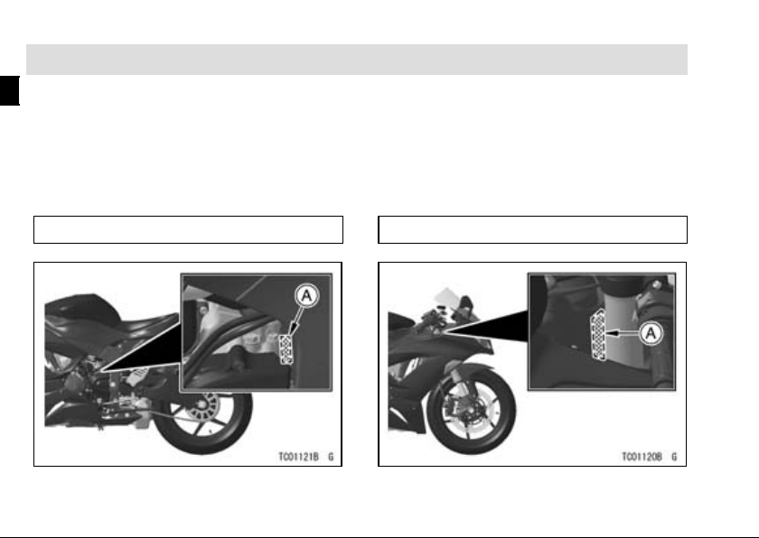
Location of Labels
All warning labels which are on your
vehicle are repeated here. Read labels
on your vehicle and understand them
thoroughly. They contain information
which is important for your safety and
the safety of anyone else who may operate your vehicle. Therefore, it is very
important that all warning labels be on
your vehicle in the locations shown. If
any label is missing, damaged, or worn,
get a replacement from your Kawasaki
dealer and install it in the co rrect position.
NOTE
The sample warning labels in this
○
section have part numbers to help
GENERAL INFORMATION 29
you and your dealer obtain the correct replacement.
Refer to the actual vehicle label for
○
model specific d ata grayed out in the
illustration.
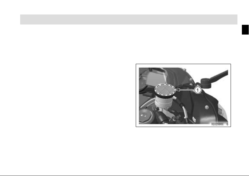
1. Brake Fluid (Front)

30 GENERAL INFORMATION
2. Brake Fluid (Rear)
3. Battery Poison/Danger
4. Rear Shock Ab sorb er Warning

GENERAL INFORMATION 31
5. Radiator Cap Danger
6. Fuel Notice
*7. Fuel Level
8. Vehicle Emission Control Information
*: only on California model

32 GENERAL INFORMATION
*9. Vacuum Ho se Routing Diagram
10. Noise Emission Control Information
11. Weight and Manufacture
12. Important Drive Chain Information
13. Tire and Load Data
*: only on California model

GENERAL INFORMATION 33
1)
2)
3)

34 GENERAL INFORMATION
4) 5)
6)

GENERAL INFORMATION 35
7) only on California model
8)
8) only on California model

36 GENERAL INFORMATION
9) only on California model 10)
11)

12) 13)
GENERAL INFORMATION 37

38 GENERAL INFORMATION
Location of Parts
1. Rear View Mirrors
2. Clutch Lever
3. Starter Lockout Switch
4. Meter Instrument
5. Brake Fluid Reservoir (Front)
6. Front Brake Lever
7. Throttle Grip
8. Left Handlebar Switches
9. Spring Preload Adjuster
10. Ignition Switch/Steering Lock
11. Rebound Damping Force Adjuster
12. Compression Damping Force
Adjuster

GENERAL INFORMATION 39
1. Headlight
2. Fuse Box
3. Spark Plugs
4. Fuel Tank
5. Compression
Damping Force
Adjuster
6. Battery
7. Tool Kit
8. Turn Signal Lights
9. License Plate Light
10. Front Fork
11. Radi ator
12. Idle Adjust Screw
13. Side Stand Switch
14. Shift Pedal
15. Rebound Damping
Force Adjuster
16. Swingarm
17. Drive Chain
18. Chain Adjuster
19. Seat Lock

40 GENERAL INFORMATION
1. Tail/Brake Light
2. Passenger’s Seat
3. Rider’s Seat
4. Rear Shock Absorber
5. Brake Fluid Reservoir (Rear)
6. Fuel Tank Cap
7. Air Cleaner
8. Muffler
9. Brake Calipers
10. Brake Disks
11. Rear Brake Light Switch
12. Rear Brake Pedal
13. Oil Level Inspection Window
14. Coolant Reserve Tank

Meter Instruments
A. Tachometer
B. RESET Button
C. MODE Button
D. Yellow Shift Up Indicator
Light
E. Yellow Engine Warning
Indicator Light
F. Amber Fuel Level Warning
Indicator Light
G. Blue High Beam Indicator
Light
H. Green Neutral Indicator
Light
I. Green Turn Signal Indicator
Light
J. Red Warning Indicator
Light
K. Multifunction Meter
L. Yellow KTRC Warning
Indicator Light
GENERAL INFORMATION 41

42 GENERAL INFORMATION
(For models equipped KIBS)
A. Tachometer
B. Reset Button
C. Mode Button
D. Yellow Shift Up Indicator
Light
E. Yellow Engine Warning
Indicator Light
F. Amber Fuel Level Warning
Indicator Light
G. Blue High Beam Indicator
Light
H. Green Neutral Indicator
Light
I. Green Turn Signal Indicator
Light
J. Red Warning Indicator
Light
K. Multifunction Meter
L. Yellow Warning Indicator
Light
M. Yellow ABS Indicator L igh t

NOTE
For safety, do not operate the instru-
○
ment buttons while riding the motorcycle.
Tachometer
The tachometer shows th e engine speed in revolutions per minute
(r/min, rpm). On the right side of the
tachometer face is a portion called
the“redzone.”Enginer/min(rpm)in
the red zone is above maximum recommended engine speed and is also
above the range for good performance.
NOTICE
Engine r/min (rpm) should not
be allowed to enter the red zone;
operation in the red zone will
overstress the engine and may
cause serious engine damage.
GENERAL INFORMATION 43
A. Tachometer
B. Red Zone
When the ignition switch is turned
on, the tachometer needle momentarily goes from the minimum to the maximum, then goes back from the maximum to the minimum reading to check
its operation. If the tachometer does
not operate correctly, have it checked
by an authorized Kawasaki dealer.

44 GENERAL INFORMATION
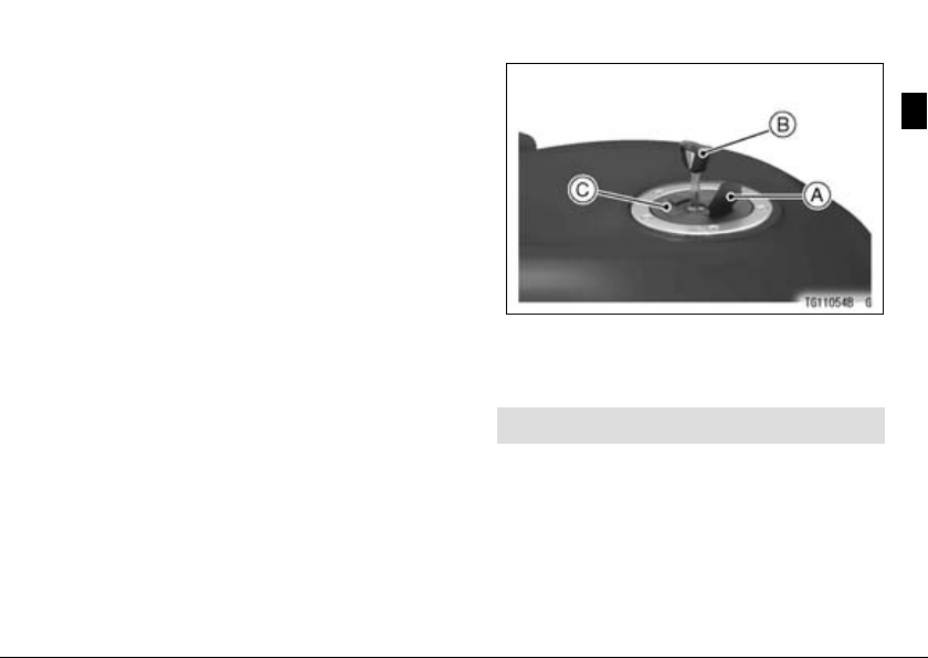
Multifunction Meter
A. Coolant Temperature Meter
B. Gear Position Indicator
C. Power Mode Indicator
D. KTRC Mode Indicator
E. Multifunction Display
-Odometer
-TripMeterA/B
- Current Mi leage
- Average Mileage
-Clock
F. KTRC Level Indicator
G. Warning Symbols
H. Speedometer
I. Economical Riding Indicator
J. KIBS Warning Symbol
(for models equipped
with KIBS)
K. KTRC Warning Symbol
(for models equipped
with KIBS)

When the ignition switch is turned
on, all LCD segments are displayed
with opening display functions for few
seconds, then the multifunction meter
turns to operational mode.
Speedometer
The speedometer shows the speed
of the vehicle in digital values.
Unit Setting
The unit setting in the multifunction
meter c an be changed according to local regulations. Make sure the unit setting is correctly displayed before riding.
GENERAL INFORMATION 45
A. Meter Display Unit
NOTE
Do not operate the motorcycle with
○
wrong unit (mph or km/h) of the
speedometer.
To change the meter display units in
the multifunction meter a s follows:
Display the odometer in the multi-
•
function display.
Push the RESET button while push-
•
ing the MODE button to select the

46 GENERAL INFORMATION
meter display units. The display units
can be shifted in the following order.
Multifunction Display
The multifunction display indicates
the following modes.
Odometer
•
Trip Meter A
•
Trip Meter B
•
Current Mileage
•
Average Mileage
•
Clock
•
When the MODE button is pushed,
the display modes can be shifted as
follows.
NOTE
For safety, do not operate the instru-
○
ment buttons while riding the motorcycle.
The multifunction display is dis-
○
played in the unit depending on the
unit mode setting, refer to the Unit
Setting item in this section.

GENERAL INFORMATION 47
Odometer
The odo meter sh ows the total distance in kilometers or miles that the vehicle has run. If the odometer is displayed, the “ODO” is displayed on the
multifunction display. This meter cannot be reset.
A. Odom eter
B. “ODO”
NOTE
The data are maintained even if the
○
battery is disconnected.
When the figures come to 999999,
○
the display is stopped and locked.
Trip Meter
The trip meter has two meters which
distinguished between the “TRIP A”
and “TRIP B”. The trip meter shows
the distance in kilometers or miles traveled since it was last reset to zero.
TRIP A: 0.0 ∼ 9999.9
TRIP B: 0.0 ∼ 9999.9
A. Trip Meter
B. “TRIP A”
To reset the trip meter:
PushtheMODEbuttontoselectthe
•
trip meter A or B.
Push the RESET button and hold it
•
in.
After two seconds, the figure display
•
turns to 0 .0, a nd then starts countin g

48 GENERAL INFORMATION
when the vehicle is operated. The
meter counts until it is next reset.
NOTE
The data is maintained even if the
○
battery is disconnect.
When the trip meter reaches 9999.9
○
while riding, the meter resets to 0.0
and continues counting.
Current Mileage
This display mode shows the current
mileage by numerical value. The current mileage display is renewed every
4 seconds.
A. Current Mileage
NOTE
The numerical value shows “– –.–”
○
until 4 seconds have passed and the
speedometer is rises to above 0 km/h
(0 mph).
Average Mileage
This display mode shows the average mileage by numerical value
counted from the start of measuring
to present time. The average mileage
display is renewed every 5 seconds.
A. Average Mileage
B. “AV”
While the average milea g e is dis-
•
played, push the RESET button and

GENERAL INFORMATION 49
hold it in until the average mileage
values resets to “– –. –”.
NOTE
The d ata is maintained by backup
○
power if the ignition switch is turned
off.
When the battery is disconnected,
○
the average mileage resets to “– –.–”.
After resetting the average mileage,
○
the numerical value is not displayed
until 5 mL (0.2 US oz.) of fuel has
been used and 100 m (328 ft) has
been traveled.
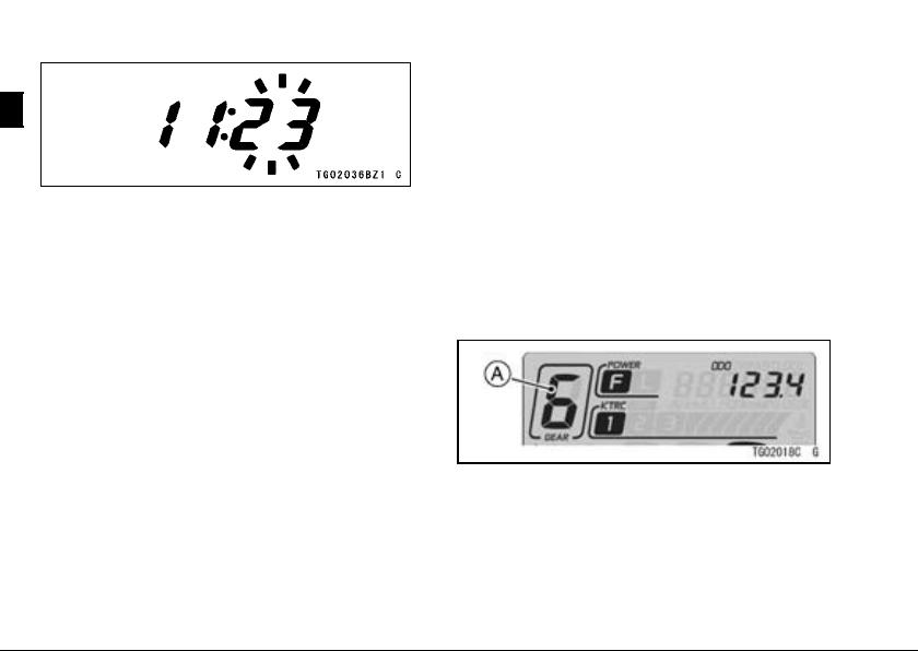
Clock
To adjust hours and minutes, do the
followings while the motorcy cle is at a
stop.
Turn the ignition switch on.
•
PushtheMODEbuttontoselectthe
•
clock.
Push the RESET button for more
•
than 2 seconds. Both the hour and
minute displays start blinking.
Push the RESET button. The hour
•
display only blinks. Push the MODE
button to advance the hours.
Push the RESET button. The hour
•
display stops blinking and the minute
display starts blinking. Push the
MODE button to advance the minutes.
50 GENERAL INFORMATION
When the battery is disconnected,
○
the clock is reset to 1:00 and starts
working again when the battery is
connected.
Push the RESET button. Both the
•
hour and minute displays start blinking again .
Push the MODE button. The dis-
•
plays stop blinking and the clock
starts working.
NOTE
Pushing the MODE button momen-
○
tarily advances the hour or minute
step by step. Pushing and holding the button advances the hour or
minute continuously.
The clock works normally by the back
○
-up power while the ignition switch is
turned off.
Gear Position Indicator
The gear position indicator shows the
corresponding gear positions where
thetransmissionisshifted.
For example, w hen the transmission
is in 6th gear, “6” is displayed.
A. Gear Position Indicator

NOTE
If the gear position is in the neutral
○
position, the gear position is disappears and the neutral indicator light
goes on.
Coolant Temperature Meter
The coolant temperature meter indicates temperature of the engine
coolant.
A. Coolant Temperature Meter
If the coolant temperature is below
•
40°C (104°F), “– – –” is displayed.
GENERAL INFORMATION 51
When the coolant temperature rises
to above 40°C (104°F), the numerical
value of the coolant temperature at the
present state is displayed.
If the coolant temperature rises to
•
above 115°C (239°F) and below
120°C (248°F), the numerical value
of the current coolant temperature
starts blinking, the warning indicator
light and coolant temperature warning symbol also go on. T his warns

52 GENERAL INFORMATION
the operator that the coolant temperature is high.
A. Coolant Temperature Warning Symbol
B. Red Warning Indicator Light
If the coolant temperature rises to
above 120°C (248°F), “HI” is displayed
and starts blinking, the warning indicator light and coolant temperature warningsymbolalsogoon. Thiswarnsthe
operator that the coolant temperature is
too high. Stop the engine and check
the coolant level in the reserve tank after the engine cools down. Have the
coolingsystemcheckedbyanauthorized Kawasaki dealer.
A. Coolant Temperature Warning Symbol
B. Red Warning Indicator Light

NOTICE
Do not let the engine continue
running when the coolant temperature shows “HI”. Prolonged
engine operation will result in
severe engine damage from
overheating.
Economical Riding Indicator
When the operator is driving the motorcycle for optimum fuel-efficiency, the
economical riding indicator appears on
the multifunction meter to indicate favorable fuel consumption. Monitoring
the economical riding indicator can
help the rider maximize fuel efficiency.
GENERAL INFORMATION 53
A. Economical Riding Indicator
WARNING
Failing to properly observe the
road ahead increases the chance
of an accident resulting in severe injury or death. Do not concentrate on the economical riding indicator by taking your eyes
off the road; observe using peripheral vision.
Power Mode Indicator
This indicator shows the selected
Power mode. For more detailed information about the Power mode, see

54 GENERAL INFORMATION
Power mode section in the HOW TO
RIDE THE MOTORCYCLE chapter.
A. Power Mode Indicator
KTRC Mode Indicator
This indicator shows the selected
KTRC mode. For more detailed information about the KTRC mode, see
Kawasaki TRaction Control (KTRC)
section in the HOW TO RIDE THE
MOTORCYCLE chapter.
A. KTRC Mode Ind icator
KTRC Level Indicator
The instantaneous strength and
weakness of the KTRC operation can
be checked with the KTRC level indicator in the multifunction meter while the
motorcycle is running. T h e stronger
thetractioncontrolworks,themorethe
segments go on.
A. KTRC Level Indicator
Indicator Lights
Green Neutral Indicator Light
N : When the transmission is in neutral,
the neutral indicator light goes on.

GENERAL INFORMATION 55
Blue High Beam Indicator Light
: When the headlight is on high
beam, the high beam indicator light
goes on.
Green Turn Signal Indicator Light
: W hen the turn signal switch is
pushed to the left or right, the turn signal indicator light blinks.
Yellow Shift Up Indicator Light
The Shift-up indicator light can be
used in closed cou rs e competition. Do
not use the s hift-up indica tor during everyday riding.
When the engine speed reaches a
pre-set spe e d, the shift-up indicator
light goes on to indicate the timing for
shifting up to prevent engine damage.
The shift-up indicator light ha s five
modes, light off, blinking (fast), blinking (slow), light on (bright) and light on
(dim). The shift-up i ndicator light t i ming
can be adjusted between 10 000 r/min
(rpm) and 16 000 r/min (rpm).
To select a shift-up indicator light
mode or adjust the shift-up engine
speed setting in the tachometer, do the
following while the engine is stopped:
Push the MODE and RESET button
•
simultaneously for more than 2 seconds. The previous shift-up engine
speed setting will be displayed in the
tachometer.
To change the shift-up indicator light
•
mode, push the MODE button and
the shift-up indicator light will shift between light off, blinking (fast), blinking (slow), light on (bright) and light
on (dim). The shift-up engine speed
canonlybeadjustedwhenthelight
is on.
To adjust the shift-up engine speed,
•
press the RESET button and the shift
-up engine speed timing advances in
250 r/min (rpm) increments up to 16

56 GENERAL INFORMATION
000 r/min (rpm). Once the reading
reaches at 16 000 r/min (rpm) while
advancing, it returns to 10 000 r/min
(rpm) and begins advancing.
A. Yellow Shift Up Indicator Light
B. Adjustable Range
To complete the adjustment, push
•
the MODE button and RESET button simultaneously for more than two
seconds. The tachometer now operates normally.
WARNING
Failing to properly observe the
road ahead increases the chance
of an accident. Do not concentrate on the shift-up indicator
light by taking yo ur eyes off the
road, observe using peripheral
vision.
When shifting down to a lower
gear, do not shift at such a high
speed that the engine r/min
(rpm) jumps excessively. Not
only can this cause engine damage, but the rear wheel may skid
and cause an accident. Downshifting should be done below 5
000 r/min (rpm) for each gear.
NOTE
Pushing and holding the RESET but-
○
ton advances the shift–up engine
speed continuously.

GENERAL INFORMATION 57
The data is maintained even if the
○
battery is disconnected.
NOTICE
Engine r/min (rpm) should not
be allowed to enter the red zone;
operation in the red zone will
overstress the engine and may
cause serious engine damage.

58 GENERAL INFORMATION
Yellow ABS Indicator Light (For
models equipped with KIBS)
: Normally the ABS indicator light goes on when the ignition switch is turned
on and goes off shortly after the motorcycle starts moving. If the ABS is normal, it
stays off. If the ABS indicator light shows any of the following, a fault or faults may
have taken place in the ABS. You should have the ABS checked by an autho rize d
Kawasaki dealer.
The light does not go on when the ignition switch is turned o n.
•
The light remains lit after the motorcycle starts moving.
•
The light goes on while riding.
•
Remember that the ABS does not function when the indicator light is on. If the
ABS fails, the front and rear brak es work normally as a conventional brak e system.

GENERAL INFORMATION 59
Status Brake Condition
Normal
Engine
information
communication
error
Battery voltage
decreases
ABS error
Low voltage
Normal brake
Yellow A B S
Indicator Light
KIBS Goes off Goes off
ABS Goes off Goes on KIBS
ABS
Blinks
Goes on Goes off
Yellow War
Indicator Light
Goes off
ning
Multifunction
Meter
None
None
None
NOTE
ABS indicator light may come on under motorcycle riding condition. (ex. The
○
front or rear wheel races.) In this case, first turn the ignition switch to off, and
then back to on, and run the motorcycle at the speed of approx. 5 km/h (3.1
mph) or above. ABS indicator light goes off by this operation, but if it remains lit,
you should have the ABS checked by an authorized Kawasaki dealer.
When the ABS indicator light is blinking, the ABS has been in the low voltage
○
mode (insufficient battery voltage). When it is in the low voltage mode, the KIBS
system does not function, but the ABS functions. To recover the KIBS system,
turn the ignition switch OFF and charge the battery. If the battery is fully charged

60 GENERAL INFORMATION
and the low voltage mode continues, you should have the KIBS checked by an
authorized Kawasaki dealer.

Warning Indicator Lights
Yellow Engine Warning Indicator
Light
: The engine warning indicator
light goes on when the ignition switch
is turned on and goes off soon after
ensuring that its circuit functions properly. This light also goes on or blinking
whenever the troubles occur in digital
fuel injection (DFI) system.
The blinking of this light indicates the
condition that the engine cannot be
started.
Refer to the Stopping the Engine section in the HOW TO RIDE THE MOTORCYCLE chapter for more information. If this light goes on, have the
DFI system checked by an authorized
Kawasaki dealer.
GENERAL INFORMATION 61
Yellow KTRC Warning Indicator
Light
: The KTRC warning indicator
light goes on and the KTRC mode
indicator and Power mode indicator
blink whenever the trouble occurs in
the KTRC system. At this time, the
KTRC system does not function. If the
KTRC warning indicator light goes on,
have the KTRC system checked by an
authorized Kawasaki dealer.
Yellow Warning Indicator Light
(For models equipped with
KIBS)
: This warning indicator light functions as the KTRC warning indicator
light and KIBS warning indicator light.
The yellow warning indicator light and
the KTRC warning symbol go on and
the KTRC mode indicator and Power
mode indicator blink whenever the trouble occurs in the KTRC system.

62 GENERAL INFORMATION
The yellow warning indicator light and
the KIBS warning symbol go on wheneverthetroubleoccursintheKIBSsystem. For more detail information about
the lighting pattern of the KIBS system,
see the Yellow ABS Indicator Light in
this chapter.
If the yellow warning indicator light
goes on, h ave the KTRC system and/or
KIBS system checked by an authorized
Kawasaki dealer.
Amber Fuel Level Warning
Indicator Light
: The fuel level warning indicator
light goes on and “FUEL” blinks in the
multifunction displa y, when approximately 3.5 L (0.9 US gal) of usable
fuel remains. Refuel at the earliest
opportunity when the fuel level warning indicator light goes on and “FUEL”
blinks.
When vehicle stands with Side
Stand, Fuel Level Warning Indicator
Light cannot show the amount of fuel
in the fuel tank exactly. Stand upright
the vehicle to check the fuel level.
A. Yellow Fuel Level Warning Indica tor Light
B. “FUE L”
NOTE
When pushing the mode button while
○
“FUEL” is displayed, the display can
be shifted to the odometer mode.

The Fuel level warning indicator light
and “FUEL” w ill blink in case of the
open or short of the wiring. Have
the wiring inspected by an authorized
Kawasaki dealer immediately.
Red Warning Indicator Light
This warning indicator light and the
oil pressure warning symbol (
should go on whenever the ignit ion
switch is turned on and go off after
starting the engine.
GENERAL INFORMATION 63
)
A. Warning Symbols
B. Red Warning Indicator Light
This warning indicator light has the
three warning functions: engine oil
pressure warning, coolant temperature warning and battery warning.
This warning indicator light goes on
with each warning symbols: e ng in e
oil pressure warning symbol (
coolant temperature warning symbol
) and battery warning symbol
(
).
(
),

64 GENERAL INFORMATION
If the red warning indicator lig ht
goes on with the engine running, have
its cause chec ked by an authorized
Kawasaki dealer.
Oil Pressure Warning Symbol
: The red warning indicator light
and the oil pressure warning symbol
) goes on whenever the oil pres-
(
sure is dangerously low or the ignition
switch is in the “ON” position with the
engine not running, and go off when
the engine oil pressure is high enough.
Refer to the MAINTENANCE AN D ADJUSTMENT chapter for more detailed
engine oil information.
Coolant Temperature Warning
Symbol
: The red warning indicator light
and the coolant tem perature warning
symbol go on whenever the coolant
temperature rises to about 115°C
(239°F) when the motorcycle is in operation. If they go on, stop the engine
and check the coolant level in the reserve tank after the engine cools down.
Havethecoolingsystemcheckedby
an authorized Kawasaki dealer.
NOTICE
Do not let the engine continue
running when the coolant temperature warning symbol goes
on. Prolonged engine operation
will result in severe damage from
overheating.
Battery Warning Symbol
: The red warning indicator light
and the battery warning symbol (
go on whenever the battery voltage is
less than 11.0 V or more than 16.0 V.
If they go on, have the battery voltage
)

GENERAL INFORMATION 65
checked by an authorized Kawasaki
dealer.
NOTE
When the all indicator lights and dis-
○
play of the multifunction meter go
off, the battery vo ltage is insufficient.
Have the machine checked by an
authorized Kawasaki dealer promptly
because the engine might stop suddenly when keeping running in that
condition.
Keys
This motorcycle has a combination
key,whichisusedfortheignition
switch, steering lock, seat lock, and
fuel tank cap.
Included with the key is a key number, which may be stamped on a separate plate. Record the key number in
the space provided and store the number in a safe place. If your keys came
with a plate, store it in a safe place as
well.
A. Ignition Key
B. Tag
C. Key Number
Write your key number here.

66 GENERAL INFORMATION
In the event you lose your keys, you
will need the key number to have a duplicate made. If you cannot locate your
key number, contact the dealer where
you purchased your Kawasaki motorcycle. It’s possible the dealer may have
the number in its records. If the key
number is lost completely, you will need
to replace the ignition switch and all
other locks operated by that key.
Contact your Kawasaki dealer to purchase additional spare keys either using your original key as a master or using the key code on the tag or your key.
Store one key at home and keep another spare in your wallet or riding gear,
in case the original is lost.
Ignition Switch/Steering Lock
This is a three-position, key-operated
switch. The key can be removed from
theswitchwhenitisinthe“OFF”or
“LOCK” position.
A. Ignition Switch/Steering Lock
B. ON position
C. OFF position
D. LOCK position

GENERAL INFORMATION 67
OFF
ON
LOCK
Engine off. Electrical circuits
off.
Engine on. All electrical
equipment can be used.
Steering locked. Engine off.
Electrical circuits off.
NOTE
The tail, city and license plate lights
○
are on whenever the ignition key is in
the “ON” position. Headlights go on
when the starter button is released
after starting the engine. To avoid
battery discharge, always start the
engine immediately after turning the
ignition key to “ON.”
Ifyouleavethekeyinthe“ON”po-
○
sition on for a long time, the battery
may become totally discharged.

68 GENERAL INFORMATION
Right Handlebar Switches
A. Engine Stop Switch
B. Starter Button
Engine Stop Switch
In addition to the ignition switch,
theenginestopswitchmustbein
the
operate.
position for the motorcycle to
Theenginestopswitchisforemer-
gency u se. If required, move the switch
to the
position.
NOTE
Although the engine stop switch
○
stops the engine, it does not turn off
all the electrical circuits. Ordin arily,
the ignition switch should be used to
stop the engine.
Starter Button
The starter button operates the electric starter when the transmission is in
neutral.
Refer to the Starting the Engine sectioninthe“HowtoRidetheMotorcycle”
chapter for starting instructions.

GENERAL INFORMATION 69
Left Handlebar Switches
A. Dimmer Switch
B. Power/KTRC Button
C. Turn Signal Switch
D. Horn Button
E. Passing Button
Dimmer Switch
High or low beam can be selected
with the dimmer switch. When the
headlight is on high beam (
high beam indicator light goes on.
), the
High beam.......(
Low beam.......(
)
)
NOTE
When the headlight is on high beam,
○
both headlights go on. When the
headlight is on low beam, only one
headlight goes on.
Turn Signal Switch
When th e turn signal sw itch is
pushed to the left (
), the corresponding turn sig-
(
nals blink on and off.
To stop blinking, push the switch in.
)orright
Horn Button
When the horn button is pushed, the
horn sounds.
Passing Button
When the passing button is pushed,
the headlight high beam (passing

70 GENERAL INFORMATION
beam) goes on to signal the driver
of the vehicle ahead that you are about
to pass. The passing light is shut off as
soon as the button is released.
Power/KTRC Button
Refer to the KTRC or Power mode
system instruc tions of the “How to Ride
the Motorcycle” chapter for operations.
Brake Lever Adjuster
There is an adjuster on the brake
lever. The adjuster has 6 positions so
that the released lever position can be
adjusted to suit the operator’s hands.
Push the lever forward and turn the adjuster to align the number with the mark
on the lev er holder. The distance from
thegriptothereleasedleverisminimum at Number 6 and maximum at
Number 1.
A. Adjus ter
B. Mark
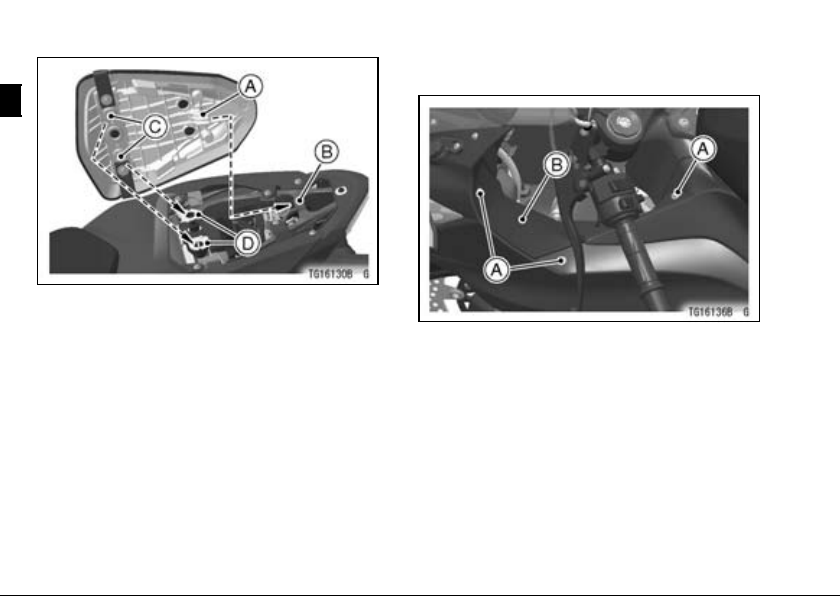
Fuel Tank Cap
To open the fuel tank cap, pull up the
key hole cover. I nsert the ignition key
into the fuel tank cap and turn the key
to the right.
To close the cap, push it down into
place with the key inserted. The key
can be removed by turning it to the left
to the original position. Close the key
hole cover.
NOTE
The fuel tank cap cannot be closed
○
without the key inserted, and the key
cannot be removed unless the cap is
locked properly.
Do not push on the key to close the
○
cap, or the cap cannot be locked.
GENERAL INFORMATION 71
A. Key Hole Cover
B. Ignition Key
C. Fuel Tank Cap
Fuel Tank
The following octane rating gasoline is recommended for the fuel tank.
Avoid filling the tank in the rain or where
heavy dust is blowing so that the fuel
does not get contaminated.

72 GENERAL INFORMATION
A. Tank Cap
B. Fuel Tank
C. Top Level
D. Filler Neck
WARNING
Gasoline is extremely flammable
and can be explosive under certain conditions, creating the potential for serious burns. Turn
the ignition switch off. Do not
smoke. Make sure the area is
well ventilated and free from any
source of flame or sparks; this
includes any appliance w ith a pilot light. Never fill the tank completelytothetop. Ifthetankis
filled completely to the top, heat
may cause the fuel to expand
and overflow through the vents
in the tank cap. After refueling,
make sure the tank cap is closed
securely. If gasoline is spilled on
the fuel tank, wipe it off immediately.

GENERAL INFORMATION 73
NOTICE
California model only: Never fill
the tank so the fuel level rises
into the filler neck. If th e tank is
overfilled, heat may cause the
fuel to expand and flow into the
Evaporative Emission Control
System resultin g in h ard starting and engine hesitation and
in compliance with the emission
regulation.
Fuel Requirement
Fuel Type
Use clean, fresh unleaded gasoline
with a minimum Antiknock Index of 90.
The Antiknock Index is posted on service station pumps. The octane rating
ofagasolineisameasureofitsresistance to detonation or “knocking.” The
Antiknock Index is an average of the
Research Octane Number (RON) and
the Motor Octane Number (MON) as
shown in the table.
Octane Rating Method
Antiknock
Index
(RON + MON)
2
Minimum
Rating
90
NOTICE
Use only unleaded gasoline.
Never use leaded gasoline.
Leaded gasoline significantly
reduces the capability of the catalytic converter in the exhaust
system.

74 GENERAL INFORMATION
NOTICE
Use minimum of 90 octane gasoline only to prevent severe engine damage.
NOTICE
If engine “knocking” or “pinging” occurs, use a different
brand of gasoline of a higher
octane rating. If this condition is
allowed to continue it can lead
to severe engine damage.
Gasoline quality is important.
Fuels of low quality or not meeting standard industry specifications may result in unsatisfactory performance. Operating
problems that result from the
use of poor quality or nonrecommended fuel may not be covered
under your warranty.
Fuels Containing Oxygenates
Gasoline frequently contains oxygenates (alcohols and ethers) especially in areas of the U.S. and Canada
which a re required to sell such reformulated fuels as part of a strategy to
reduce exhaust emissions.
The types and volume of fuel oxygenates approved for use in unleaded
gasoline by the U.S. Environmental
Protection Agency include a broad
range of alcohols and ethers, but only
two components have seen any significant level of comme rcia l use.
Gasoline/Alcohol Blends - Gasoline
containing up to 10% ethanol (alcohol produced from agricultural products
such as corn), also known as “gasohol”
is approved for use.

GENERAL INFORMATION 75
NOTICE
Avoid using blends of unleaded
gasoline and methanol (wood
alcohol) whenever possible, and
never use “gasohol” containing more than 5% methanol.
Fuel system damage and performance problems may result.
Gasoline/Ether Blends - The most
common ether is methyl tertiary butyl
ether (MTBE). You may use gasoline
containing up to 15% MTBE.
NOTE
Other oxygenates approved for use
○
in unleaded gasoline include TAME
(up to 16.7%) and ETBE (up to
17.2%). Fuel containing t hese oxygenates can also be used in your
Kawasaki.
NOTICE
Never use gasoline with an octane rating lower than the minimum specified by Kawasaki.
Never use “gasohol” with more
than 10% ethanol, or more than
5% methanol. Gasoline containing methanol must also be
blended with cosolvents and
corrosion inhibitors.
Certain ingredients of gasoline
may cause paint fading or damage. Be extra careful not to spill
gasoline or gasoline oxygenate
blends during refueling.
When not operating your
Kawasaki for 30 to 60 days, mix a
fuel stabilizer (such a s STA-BIL)
withthegasolineinthefueltank.
Fuel stabilizer additives inhibit
oxidation of the fuel which minimizes gummy deposits.

76 GENERAL INFORMATION
NOTICE
Never store this product with
“gasohol” in the fuel system.
Beforestorageitisrecommended that you drain all fuel
from the fuel system. See the
Storage section in this manual.
Side Stand
The motorcycle is equipped with the
side stand.
A. Side Stand
NOTE
When using the side stand, turn the
○
handlebar to the left.
Do not sit on the motorcycle while it is
on its side stand. Always kick the stand
fully up befor e sitting on the motorcycle.

NOTE
The motorcycle is equipped with a
○
side stand switch. This switch is designed so that the engine does not
start if the transmission is in gear and
the side stand is down .
Seat
GENERAL INFORMATION 77
Passenger’s Seat Removal
Insert the ignitio n key into the se a t
•
lock.
Remove the passenger’s seat up-
•
ward while turning the key clockwise.
A. Ignition Key
B. Seat Lock
C. Passenger’s Seat
Passenger’s Seat Installation
Insert the tab on the rear of the pas-
•
senger’s seat into the slot in the
frame.
Insert the projections at the front of
•
the passenger’s seat into the holes
on the frame.
Push down the front part of the pas-
•
senger’s seat until the lock clicks.
78 GENERAL INFORMATION
A. Tab
B. Slot
C. Projections
D. Holes
Pull up the front and rear ends of the
•
passenger’s seat to make sure they
are securely locked.
Rider’s Seat Removal
Remove the bolts and washers on
•
the inner cover.
Remove the inner cover.
•
A. Bolts and Washers
B. Inner Cover
Remove the wellnut.
•
Pull out the side cover out slowly to
•
clear the projections and the hook
-and-loop fasteners.
Clear the hook and remove the side
•
cover.

GENERAL INFORMATION 79
A. Wellnut
B. Projections
C. Hook-and-Loop Fasteners
D. Hook
E. Side Cover
Remove the other side of the inner
•
cover and side cover in the same
way.
Remove the bo lts and pull off the s e at
•
upward.
A. Bolt (Both Sides)
B. Rider’s Seat
Rider’s Seat Installation
Insert the tab on the rear of the rider’s
•
seat into the slot in the frame and
tighten the bolts.

80 GENERAL INFORMATION
A. Rider’s Seat
B. Tab
C. Slot
When install the side cover, insert the
•
hook into the slot, and then insert the
projections into the holes and attach
the hook-and-loop fasteners.
Install the wellnut.
•
A. Ho ok
B. Slot
C. Projections
D. Holes
E. Hook-and-Loop Fasteners
Install the inner cover.
•
Install the bolts and washers.
•
Install the other side of the inner
•
cover and side cover in the same
way.

Helmet Hooks
Helmets can be secured to the motorcycle using the helmet hooks. The helmet hooks are located under the passenger’s seat.
WARNING
Riding with helmets attached to
the hooks could cause an ac-
cident by distracting the oper-
ator or interfering with normal
vehicle operation. Do not ride
the motorcycle with helmets at-
tached to the hooks.
GENERAL INFORMATION 81
A. Helmet Hooks
Tool Kit
The tool kit is located under the pas-
senger’s seat.
The kit contains tools that can be
helpful in making roadside repairs,
adjustments, and some maintenance
procedures explained in this manual.
Keep the tool kit in the original place.

82 GENERAL INFORMATION
A. Tool Kit
B. Band
Air Cleaner Intake
The air cleaner intake allows air to
enter the fue l system. Never allow anything to restrict the flow of air into the
air cleaner. A res tricted air cleaner will
reduce performance and increase exhaust emissions.
A. Air Cleaner Intake
Event Data Recorder
This vehicle is equipped at the factory with an event data recorder (EDR).
The main purpose of this device is to
record data that assists with understanding of how a vehicle’s systems
performed during a short period of time.
Among other things, this data can help
provide a better understanding of the

GENERAL INFORMATION 83
circumstances in which crashes occur. This device does not collect or
store personal data or information (e.g.
name, gender, age). The EDR in this
vehicle is designed to record such data
as: vehicle speed, engine crankshaft
rotational speed, throttle opening.
To read the data recorded by the
EDR, special equipment is required,
and access to the vehicle or EDR is
necessary. In addition to Kawasaki,
other parties, such as law enforcem ent
that have special equipment, can read
the information if they have access to
the EDR. Kawasaki does not access
the EDR information without obtaining
consent, unless pursuant to court order
or where required by law enforcement ,
other government authorities, or other
third parties acting with lawful authority. Other parties may seek to access
the recorded data independently of
Kawasaki.
84 HOW TO RIDE THE MOTORCYCLE
HOW TO RIDE THE MOTORCYCLE
Break-In
The first 1 600 km (1 000 mi) that the
motorcycle is ridden is designated as
the break-in period. If the motorcycle
is not used carefully during this period,
you may very well end up with a “broken down” instead of a “broken in” motorcycle after a few thousand kilometers.
The following rules should be observed during the break-in period.
The table shows maximum recom-
•
mended engine speed during the
break-in period.
Distance traveled
0 ∼ 800 km (0 ∼
500 mi)
800 ∼ 1600km
(500 ∼ 1 000 mi)
Maximum engine
speed
4 000 r/min (rpm)
6 000 r/min (rpm)
NOTE
When operating on public roadways,
○
keep maximum speed under traffic
law limits.
Do not start moving or race the en-
•
gine immediately after starting it,
even if the engine is already warm.
Run the engine for two or three minutes at idle speed to give the o il a
chance to wo rk up into all the engine
parts.

HOW TO RIDE THE MOTORCYCLE 85
Do not race the engine while the
•
transmission is in neutral.
WARNING
New tires are slippery and may
cause loss of control and injury.
A break-in period of 160 km (100
miles) is necessary to establish normal tire traction. During
break-in, a void sudden and maximum braking and acceleration,
and hard cornering.
In addition to the above, at 1 000 km
(600 mi) it is extremely important tha t
the owner has the initial maintenance
service performed by a competent mechanic following the procedures in the
Service Manual.
Starting the Engine
Check that the engine stop switch is
•
in the
A. Engine Stop Switch
B. Starter Button
Turn th e ignition key to “ON” position.
•
Makesurethetransmissionisinneu-
•
tral.
position.

86 HOW TO RIDE THE MOTORCYCLE
motorcycle falls down. The engine
warning indicator light (
when the starter button is pressed if
the engine cannot be started. After
righting the motorcycle, first turn the
ignition key to “OFF” and then back
to “ON” before starting the engine.
Without holding the throttle grip, push
•
the starter button to start the e ngine.
) blinks
A. Green Neutral Indicator Light
B. Ignition Switch
C. ON position
NOTE
The motorcycle is equipped with a
○
vehicle-down sensor which causes
the engine to stop automatically if the
NOTE
While the engine is cold, the fast idle
○
system automatically raises the engine idling speed. At this time , the
engine warning indicator light may go
on if you operate the throttle grip unnecessarily.

NOTICE
Do not operate the starter con-
tinuously for more than 5 sec-
onds, or the starter will overheat
and the battery power will drop
temporarily. Wait 15 seconds
between each operation of the
starter to let it cool and the bat-
tery power recover.
HOW TO RIDE THE MOTORCYCLE 87
NOTE
The motorcycle is equipped with a
○
starter lockout sw itch. This switch is
designed so that the engine does not
start if the transmission is in gear and
the side stand is down. However, the
engine can be started if the clutch
lever is pulled and the side stand is
fully u p.
A. Clutch Lever
B. Starter Lockout Switch
NOTICE
Donotlettheengineidlelonger
than five minutes, or engine
overheating and damage may
occur.

88 HOW TO RIDE THE MOTORCYCLE
Jump Starting
If your motorcycle battery is “run
down”, it should be removed and
charged. If this is not pra ctica l, a 12
volt booster battery and jumper cables
may be used to start the engine.
DANGER
Battery acid generates hydrogen gas which is flammable and
explosive under certain conditions. It is present within a
battery at all times, even in a
discharged condition. Keep all
flames and sparks (cigarettes)
away from the ba ttery. Wear eye
protection when working with a
battery. In the event of battery
acid contact with skin, eyes, or
clothing, wash the affected areas immediately with water for at
least five minutes. Seek medical
attention.
Connecting Jumper Cables
Make sure the ignition switch is
•
turned off.
Remove the side cover and rider’s
•
seat.

Slide the red cap from the positive (+)
•
terminal.
Connect a jumper cable from the
•
positive (+) terminal of the booster
battery to the positive (+) terminal of
the motorcycle battery.
NOTICE
Be careful not to contact the
jumper cable slip on the positive
battery terminal to the frame, or
it will cause a short circuit.
HOW TO RIDE THE MOTORCYCLE 89
A. Motorcycle Battery Positive (+) Terminal
B. From Boos ter Battery P ositive (+) Terminal
C. Shift Pedal Bracke t
D. From Booster Battery Negative (–)
Terminal
Connect another jumper cable from
•
the negative (–) terminal of the
booster battery to your motorcycle
shift pedal bracket or other unpainted
metal surface. Do not use the negative (–) terminal of the battery.

90 HOW TO RIDE THE MOTORCYCLE
DANGER
Batteries contain sulfuric acid
that can cause burns and pro-
duce hydrogen gas which is
highly explosive. Do not make
this last connection at the fuel
system or battery. Take care not
to touch the positive and nega-
tive cables together, and do not
lean over the battery when mak-
ing this last connection. Do not
connect to a frozen battery. It
could explode. Do not reverse
polarity by connecting positive
(+) to negative (–), or a battery
explosion and serious damage
to the electrical system may oc-
cur.
Follow the standard engine starting
•
procedure.
NOTICE
Do not operate the starter continuously for more than 5 seconds or the starter will overheat
and the battery power will drop
temporarily. Wait 15 s ec onds
between each operation of the
starter to let it cool and the battery power recover.
After the engine has started, discon-
•
nect the jumper cables. Disconnect
the negative (–) cable from the motorcycle fir s t.
Reinstall the parts removed.
•
Moving Off
Check that the s ide stand is up.
•
Pull in the clutch lever.
•
Shift into 1st gear.
•

HOW TO RIDE THE MOTORCYCLE 91
Open the throttle a little, and start to
•
let out the clutch lever very slowly.
As the clutch starts to engage, open
•
the throttle a little more, giving the engine just enough fuel to keep it from
stalling.
A. Shift Pedal
NOTE
Themotorcycleisequippedwitha
○
side stand switch. This switch is designed so that the engine does not
start if the transmission is in gear and
the side stand is down.
Shifting Gears
Close the th ro ttle while pulling in the
•
clutch lever.
Shift into the next higher or lower
•
gear.
Open the throttle part way, while re-
•
leasing the clutch lever.
For smooth riding, each gear position
•
should cover the proper rate of speed
shown in the table.

92 HOW TO RIDE THE MOTORCYCLE
WARNING
Downshifting to a lower gear at
high speed causes engine rpm
to increase excessively, poten-
tially damaging the engine and
it may also cause the rear wheel
to skid and cause an accident.
Downshifting should be done
below the vehicle speeds for
each gear shown in the table.
Vehicle speed when shifting
Shifting up km/h (mph)
1st → 2nd 15 ( 9)
2nd → 3rd 25 (15)
3rd → 4th 35 (21)
4th → 5th 45 (27 )
5th → 6th 55 (34 )
Shifting down km/h (mph)
6th → 5th 30 (19)
5th → 4th 25 (15)
4th → 3rd 20 (12)
3rd → 2nd 15 ( 9)
2nd → 1st 15 ( 9)
NOTE
Thetransmissionisequippedwitha
○
positive neutral finder. When the motorcycle is standing still, the transmission cannot be shifted past neutral
from 1st gear. To use the positive
neutral finder, shift down to 1st gear,
then lift up on the shift pedal while
standing still. The transmission will
shift only into neutral.

HOW TO RIDE THE MOTORCYCLE 93
Braking
Close the throttle completely, leav-
•
ing the clutch engaged (except when
shifting gears) so that the eng in e will
help slow down the motorcycle.
Shift down one gear at a time so that
•
you are in 1st gear when you come
to a complete stop.
When stopping, always apply both
•
brakes at the same time. Normally
the front brake sho uld be applied a little more than the rear. Shift down or
fully disengage the clutch as necessary to keep the engine from stalling.
Never lock the brakes, or it will cause
•
the tires to skid. When turning a corner, it is better not to brake at all. Reduce your speed before you get into
the corner.
Even in motorcycles equipped with
•
ABS, braking during cornering may
cause wheel slip. When turning a
corner, it is better to limit braking to
the light application of both brakes
or not to brake at all. Reduce your
speed before you get into the corner.
For emergency braking, disregard
•
downshifting, and concentrate on
applying the brakes as hard as possible without skidding.
A. Front Brake Lever

94 HOW TO RIDE THE MOTORCYCLE
A. Rear Brake Pedal
Kawasaki Intelligent anti-lock Brake System (KIBS, For models equipped with KIBS)
KIBS re gu la tes anti-loc k braking performance with more precision during
sports riding compared to a conventional ABS system.
KIBS is designed to help prevent
thewheelsfromlockingupwhenthe
brakes are applied hard while riding
straight. KIBS automatically regulates
brake force using engine data in addition to front and rear wheel speed
to help prevent wheel lock-up and allows more stab le steering control while
stopping.
KIBS helps pro vid e stability while
stopping by preventing wheel lock-up,
but you should be aware of the following:
To apply the brakes effectively, use
•
the front brake lever and rear brake
pedal simultaneously in the same
manner as a conventional motorcycle brake system.
KIBS cannot compensate for ad-
•
verse road conditions, misjudgment
or improper application of brakes.
You must use the same discretion

HOW TO RIDE THE MOTORCYCLE 95
as you would with motorcycles not
equipped with KIBS.
KIBS is not designed to shorten the
•
braking distance. On loose, uneven
or downhill surfaces, the stopping
distance of a motorcycle with KIBS
may be longer than that of an equivalent motorcycle without KIBS. Use
special caution in such areas.
KIBS will help prevent wheel lock-up
•
when braking in a straight line, but it
cannot control wheel slip which may
be caused by braking during cornering. When turning a corner, it is better to limit braking to a light application of both brakes or not to brake at
all. Reduce your speed before you
get into the corner.
Same as conventional brake system,
•
an excessive sudden braking may
cause wheel lock up that makes it
harder to control a motorcycle.
KIBS will not prevent the rear wheel
•
lifting.
WARNING
KIBS cannot protect the rider
from all possible hazards and
is not a substitute for safe riding practices. Be aware of how
the KIBS system operates and
its limitations. It is the rider’s
responsibility to ride at appropriate speeds and manner for
weather, road surface and traffic
conditions.
The computers integrated in
•
the KIBS compares vehicle
speed with wheel speed. Since
non-recommended tires can affect
wheel speed, they may cause the

96 HOW TO RIDE THE MOTORCYCLE
computers to make incorrect calculations that can extend braking
distance.
WARNING
Use of non-recommended tires
can cause the KIBS to malfunctionandleadtoextendedbraking distanc e, resultin g in a crash
causing serious injury or death.
Always use the recommended
standard tires for this motorcycle.
NOTE
When the KIBS is functioning, you
○
may feel a pulsing in the brake lever
and/or pedal. This is normal. Maintain pressure on the lever and/or
pedal for most effective braking.
KIBS does not function below speeds
○
of approx. 5 km/h (3.1 mph).
KIBS does not function if the battery
○
is discharged. When riding with an
insufficiently charged battery, KIBS
may not function. Keep the battery in
good condition according to the “Battery Maintenance” section.
Stopping the Engine
Close the throttle completely.
•
Shift the transmission into neutral.
•
Turn the ignition key to “OFF.”
•
Support the motorcycle on a firm,
•
level surface with the side stand.
Lock the steering.
•
NOTE
The motorcycle is equipped with a
○
vehicle-down sensor which c auses
the engine to stop automatically if the
motorcycle falls down. The engine
warning indicator light (
) blinks

HOW TO RIDE THE MOTORCYCLE 97
when the starter button is pressed if
the engine cannot be started. After
righting the motorcycle, first turn the
ignition key to “OFF” and then back
to “ON” before starting the engine.
Stopping the Motorcycle in an Emergency
Your Kawasaki Motorcycle has been
designed and manufactured to provide you optimum safety and convenience. However, in order to fully benefit from Kawasaki’s safety engineering
and craftsmanship, it is essential that
you, the owner and operator, properly
maintain your motorcycle and become
thoroughly familiar with its operatio n.
Improper maintenance can create a
dangerous situation known as throttle f ailure. Two of the most common
causes of throttle failure are:
1. An improperly serviced or clogged
air cleaner may allow dirt and dust
to enter the throttle body and stick
the throttle open.
2. During removal of the air cleaner,
dirt is allowed to enter and jam the
fuel injection system.
In an emergency situation such as
throttle failure, your vehicle may be
stopped by applying the brakes and
disengaging the clutch. Once this
stopping procedure is initiated, the engine stop switch may be used to stop
the engine. If the engine stop switch is
used, turn off the ignition switch after
stopping the motorcycle.

98 HOW TO RIDE THE MOTORCYCLE
Parking
WARNING
Operating or parking the vehicle near flammable materials can
cause a fire, and can result in
property damage or severe personal injury.
Do not idle or park your vehicle
in an area where tall or dry vegetation, or other flammable materials could come into contact
with the muffler or exhaust pipe.
WARNING
The engine and exhaust system
get extremely hot during normal
operation and can cause serious
burns.
Never touch a hot engine, exhaust pipe, or muffler during operation or after stopping the engine.
Shift the transmission into neutral
•
and turn the ignition key to “OFF.”
Support the motorcycle on a firm,
•
level surface with the side stand.
NOTICE
Do not park on a soft or steeply
inclined surface, or the m o torcycle may fall over.
If parking inside a garage or other
•
structure, be sure it is well ventilated

HOW TO RIDE THE MOTORCYCLE 99
and the motorcycle is not close to
any sou rce of flame or sparks; this
includes any appliance with a pilot
light.
WARNING
Gasoline is extreme ly flammable
and can be explosive under certain conditions, creating the potential for serious burns. Turn
the ignition switch to “OFF”. Do
not smoke. Make sure the area is
well ventilated and free from any
source of flame or sparks; this
includes any appliance with a pilot light.
Lock the steering to help prevent
•
theft.
Kawasaki TRaction Control (KTRC)
KTRC is an intelligent system that
calculates the slip level of the rear
wheel (wheelspin) during acceleration
and controls the optimum slip ratio to
suit the riding conditions. KTRC can
contribute to a stable ride not only for
sports riding but also when riding on a
rough or slippery road surface.
KTRC is designed for use on public
roads. KTRC cannot respond to every condition. Acceleration may be delayed under certain conditions.
 Loading...