

Page 1

FS730V Electronic Fuel Injection
4 stroke air-cooled V-twin gasoline engine
OWNER’S MANUAL
Page 2

Page 3

SAFETY AWARENESS
Whenever you see the symbols shown below,
heed their instructions! Always follow safe operating
and maintenance practices.
DANGER
DANGER indicates a hazardous situation
which, if not avoided, will result in death or
serious injury.
WARNING
WARNING indicates a hazardous situation
which, if not avoided, could result in death
or serious injury.
NOTICE
NOTICE is used to address practices not
related to personal injury.
NOTE
○NOTE indicates information that may help or guide
you in the operation or service of the vehicle.
Page 4
READ THIS FIRST
For your safety, read this Owner’s Manual and understand it thoroughly before operating this ENGINE.
DANGER
Exhaust gas contains carbon monoxide, a colorless, odorless poisonous gas. Inhaling carbon monoxide can cause
serious brain injury or death.
DO NOT run the engine in enclosed areas. Operate only in a well-ventilated area. Gasoline is extremely ammable
and can be explosive under certain conditions, creating the potential for serious burns. When refueling, servicing
fuel system, draining gasoline and/or adjusting the carburetor:
Stop engine and allow it to cool before refueling.
DO NOT smoke.
Make sure the area is well-ventilated and free from any source of ame or sparks, including the pilot light of any
appliance.
DO NOT ll the tank so the fuel level rises into the ller neck or level surface of level gauge. If the tank is overlled,
heat may cause the fuel to expand and overow through the vents in the tank cap.
Wipe off any spilled gasoline immediately.
Engines can become extremely hot during normal operation.
To prevent re hazard:
Keep the engine at least 1 m (3.3 ft) away from buildings, obstructions and other burnable objects.
DO NOT place ammable objects close to the engine.
DO NOT expose combustible materials to the engine exhaust.
DO NOT use the engine on any forest covered, brush covered or grass covered unimproved land unless spark
arrester is installed on the mufer.
To avoid getting an electric shock, DO NOT touch spark plugs, plug caps or spark plug leads during engine
running.
To avoid a serious burn, DO NOT touch a hot engine or mufer. The engine becomes hot during operation. Before
you service or remove parts, stop engine and allow the engine to cool.
DO NOT place hands or feet near moving or rotating parts. Place a protective cover over pulley, V belt or coupling.
DO NOT run engine at excessive speeds. This may result in injury.
Always remove the spark plug caps from spark plugs when servicing the engine to prevent accidental starting.
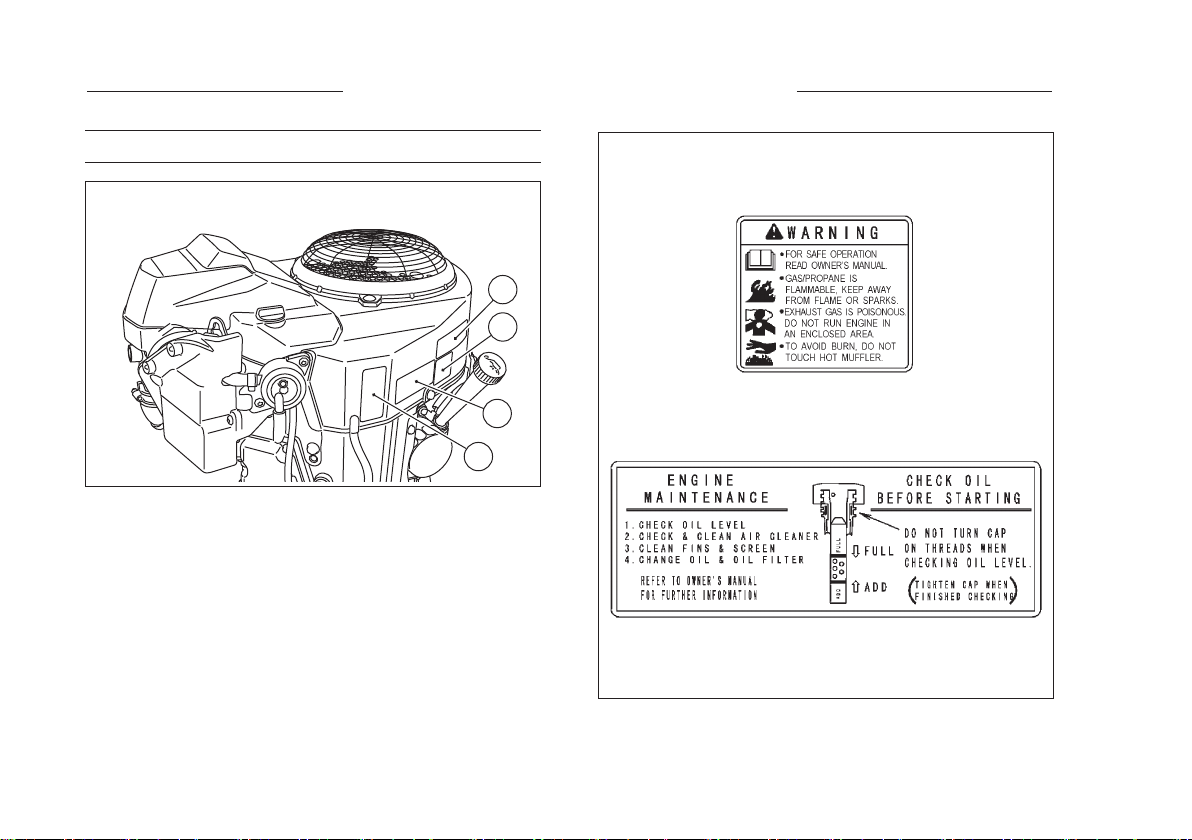
Read warning labels which are on the engine and understand them. If any label is missing, damaged, or worn get a
replacement from your Kawasaki engine dealer and install it in the correct position.
Page 5

EMISSION CONTROL INFORMATION
Fuel Information
THIS ENGINE IS CERTIFIED TO OPERATE ON UNLEADED REGULAR GRADE GASOLINE ONLY. A
minimum of 87 octane of the antiknock index is recommended. The antiknock index is posted on service station
pumps in the U.S.A.
Emission Control Information
To protect the environment in which we all live, Kawasaki has incorporated an exhaust emission control
system in compliance with applicable regulations of the United States Environmental Protection Agency and
the California Air Resources Board. Also, depending on when your engine was produced, it may have an
assigned emissions durability period.
* See below for the engine emissions durability period that may apply to your engine.
Exhaust Emission Control System
The exhaust emission control system applied to this engine consists of a Electronic Fuel Injection (EFI)
system and an ignition system having optimum ignition timing characteristics. The EFI system has been
calibrated to provide lean air/fuel mixture characteristics and optimum fuel economy with a suitable air cleaner
and exhaust system.
A sealed-type crankcase emission control system is also used to eliminate blow-by gasses. The blow-by
gasses are led to a breather chamber through the crankcase and from there to the air cleaner.
Engine Emission Compliance Period
California
Engines Greater Than or Equal To 225cc
Model Year-2015 and later
Durability period-500 hours
All Other States
Engines Greater Than or Equal To 225cc
Model Year-2015 and later
Durability Period-500 hours (Category B)
* If your engine has an assigned emissions durability period it will be located on the certication label
attached to the engine (IMPORTANT ENGINE INFORMATION).
Page 6

High Altitude Performance Adjustment Information
To improve the EMISSIONS CONTROL PERFORMANCE of engines operated above 1000 meters
(3300 feet), Kawasaki requires the following Environmental Protection Agency (EPA) and California Air
Resources Board (CARB) approved modications. High altitude adjustment requires replacement of carburetor
main jets. Installation of these optional parts may be performed by an authorized Kawasaki dealer, or the
consumer, following repair recommendations specied in the appropriate Kawasaki Service document or parts
catalog.
Operating with wrong conguration at an altitude may increase its emission and decrease fuel efciency and
performance.
NOTE
○When properly performed, these specied modications only are not considered to be emissions system
"tampering" and engine performance is generally unchanged as a result.
○Engine models with fuel injection do not require high altitude performance adjustment.
Maintenance and Warranty
Proper maintenance is necessary to ensure that your engine will continue to have low emission levels. This
Owner’s Manual contains those maintenance recommendations for your engine. Those items identied by the
Periodic Maintenance Chart are necessary to ensure compliance with the applicable standards.
As the owner of the engine, you have the responsibility to make sure that the recommended maintenance is
carried out according to the instructions in this Owner’s Manual at your own expense.
The Kawasaki Limited Emission Control System Warranty requires that you return your engine to an
authorized Kawasaki dealer for remedy under warranty. Please read the warranty carefully, and keep it valid by
complying with the owner’s obligations it contains.
Page 7

Tampering with Emission Control System Prohibited
Federal law and California State law prohibits the following acts or the causing there of: (1) the removal or
rendering inoperative by any person other than for purposes of maintenance, repair, or replacement, of any
device or element of design incorporated into any new engine for the purposes of emission control prior to its
sale or delivery to the ultimate purchaser or while it is in use, or (2) the use of the engine after such device or
element of design has been removed or rendered inoperative by any person.
Among those acts presumed to constitute tampering are the acts listed below:
Do not tamper with the original emission related parts:
●Carburetor or fuel injection system, and their internal parts
●Spark Plug
●Magneto or electronic ignition system
●Fuel lter element
●Air cleaner element
●Crankcase
●Cylinder head
●Breather chamber and internal parts
●Intake pipe and tube
Page 8

FOREWORD
We wish to thank you for purchasing this Kawasaki engine.
Please read this Owner’s Manual carefully before starting your new engine so that you will be thoroughly
familiar with the proper operation of your engine’s control, its features, capabilities and limitations.
Also read the manual of the equipment to which this engine is attached.
To ensure a long, trouble-free life for your engine, give it the proper care and maintenance described in this
manual. Always keep this manual at your ngertip so that you can refer to it whenever you need information.
This manual should be considered a permanent part of the engine and should remain with the engine when it
is sold.
Please note that the photographs and illustrations shown in this manual are based on Model FS730V EFI as
a typical example among other similar models.
All rights reserved. No part of this publication may be reproduced without our prior written permission.
This publication includes the latest information available at the time of printing. However, there may be minor
differences between the actual product and illustrations and text in this manual.
All products are subject to change without prior notice or obligation.
KAWASAKI HEAVY INDUSTRIES, LTD.
Motorcycle & Engine Company
© 2014 Kawasaki Heavy Industries, Ltd. Dec. 2014 (1) (I)
Page 9

TABLE OF CONTENTS
TABLE OF CONTENTS ..................................... 7
GENERAL INFORMATION ................................ 8
Location of Safety Related Labels ................... 8
Location of Parts ............................................. 9
Engine Serial Number ..................................... 10
Tune-up Specications .................................... 10
Engine Oil Capacity ......................................... 11
Battery Capacity .............................................. 11
FUEL AND OIL RECOMMENDATIONS ............ 12
Fuel ................................................................. 12
Engine Oil ........................................................ 13
Fuel ................................................................. 14
PREPARATION ................................................. 14
Engine Oil ........................................................ 15
STARTING ......................................................... 16
Start Engine ..................................................... 16
OPERATING ...................................................... 18
Warming Up .................................................... 18
Engine Inclination ............................................ 19
STOPPING ......................................................... 20
Stopping the Engine ........................................ 20
Ordinary Stop ............................................... 20
Emergency Stop ........................................... 20
ADJUSTMENT ................................................... 21
Engine Speed Adjustment ............................... 21
MAINTENANCE ................................................. 22
Periodic Maintenance Chart ............................ 22
Oil Level Check ............................................... 24
Oil Change ...................................................... 25
Oil Filter Change ............................................. 26
Air Cleaner Service ......................................... 27
Foam Element .............................................. 27
Paper Element .............................................. 27
Fuel Filter and Fuel Pump Service .................. 29
Spark Plug Service .......................................... 30
Fuse Service ................................................... 31
MIL (Malfunction Indicator Light) ..................... 31
Cooling System Cleaning ................................ 32
STORAGE .......................................................... 35
Engine Storage Procedure .............................. 35
TROUBLESHOOTING GUIDE ........................... 36
ENVIRONMENTAL PROTECTION .................... 37
SPECIFICATIONS ............................................. 38
WIRING DIAGRAM ............................................ 39
Page 10
8 GENERAL INFORMATION
GENERAL INFORMATION
Location of Safety Related Labels
A. Engine Maintenance
B. Warning Label
C. Emission Label
D. Product Label (Engine Serial Number)
A
B
C
D
Page 11

GENERAL INFORMATION 9
Location of Parts
D
M
N
K
L
G
G
J
D
H
A
I
R
E
P
O
F
B
F
C
A. Oil Gauge / Filler
B. Oil Filter
C. Oil Drain Plug
D. Air Cleaner
E. Throttle Body / ECU
F. Spark Plug Cap /
Spark Plug
G. Guard /
Air Inlet Screen
H. Fan Housing
I. Electric Starter
SQ
J. Voltage Regulator
K. Fuel Tube
L. Fuel Filter
M. Fuel Pump (Electric)
N. Fuel Pump (Pulse)
O. Injector
P. Diagnostic Connector
Q. 10 Pin Connector
R. 8 Pin Connector
S. Fuse
Page 12
10 GENERAL INFORMATION
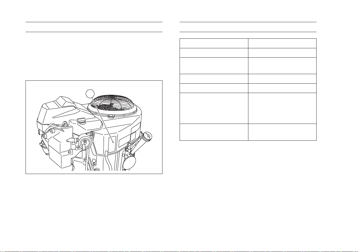
Engine Serial Number
The engine serial number is your only means of
identifying your particular engine from others of the
same model type.
This engine serial number is needed by your
dealer when ordering parts.
A
A. Engine Serial Number
Tune-up Specications
ITEM Specications
Ignition Timing Unadjustable
Spark Plugs:
Gap
Low Idle Speed 1550 r/min (rpm)
High Idle Speed 3600 r/min (rpm)
Valve Clearance
Other Specications
NGK BPR4ES
0.75 mm (0.030 in)
IN 0.05 - 0.10 mm
(0.002 - 0.004 in)
EX 0.05 - 0.10 mm
(0.002 - 0.004 in)
No other adjustment
needed
NOTE
○High and low idle speeds may vary depending on
the equipment on which the engine is used. Refer
to the equipment specication.
Page 13
GENERAL INFORMATION 11
Engine Oil Capacity
Engine Oil Capacity
1.8 L (1.9 US·qt)
[when oil lter is not removed]
FS730V
2.0 L (2.1 US·qt)
[when oil lter is removed]
Battery Capacity
WARNING
For electrical safety, always remove cable
from negative (–) side of battery before
attempting any repair or maintenance.
Battery Capacity Recommended
Minimum Recommended Battery Capacity
12 V 550 CCA Class
Page 14

12 FUEL AND OIL RECOMMENDATIONS
FUEL AND OIL RECOMMENDATIONS
Fuel
Use only clean, fresh, unleaded regular grade
gasoline.
NOTICE
Do not mix oil with gasoline.
Octane Rating
The octane rating of a gasoline is a measure of its
resistance to "knocking". Using a minimum of 87
octane by the antiknock index is recommended.
The antiknock index is posted on service station
pumps in the U.S.A.
NOTE
○If "knocking" or "pinging" occurs, use a different
brand of gasoline or higher octane rating.
○When not operating your kawasaki engine more
than once per month, you can mix a fuel stabilizer
with gasoline in the fuel tank. Fuel stabilizer
additive could inhibit oxidation of fuel.
Oxygenated Fuel
Oxygenates (either ethanol or MTBE) are added
to the gasoline. If you use the oxygenates, be sure
it is unleaded and meets the minimum octane rating
requirement.
The followings are the EPA approved percentages
of fuel oxygenates.
ETHANOL: (Ethyl or Grain Alcohol)
You may use gasoline containing up to 10%
ethanol by volume.
MTBE: (Methyl Tertiary Butyl Ether)
You may use gasoline containing up to 15%
MTBE by volume.
METHANOL: (Methyl or Wood Alcohol)
You may use gasoline containing up to 5%
methanol by volume, as long as it also contains
cosolvents and corrosion inhibitors to protect the
fuel system. Gasoline containing more than 5%
methanol by volume may cause starting and/or
performance problems. It may also damage metal,
rubber, and plastic parts of your fuel system.
Page 15
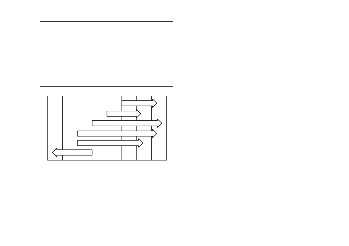
Engine Oil
The following engine oils are recommended.
API Service Classication: SF, SG, SH, SJ or SL.
Oil Viscosity
Choose the viscosity according to the temperature
as follows:
-20ºC -10ºC 0ºC 10ºC 20ºC 30ºC 40ºC
SAE40
SAE30
SAE20W-50
FUEL AND OIL RECOMMENDATIONS 13
SAE5W-20
SAE5W-20
-4ºF 14ºF 32ºF 50ºF 68ºF 86ºF 104ºF
SAE10W-40
SAE10W-30
NOTE
○Although 10W-40 engine oil is the recommended
oil for most conditions, the oil viscosity may need
to be changed to accommodate atmospheric
conditions. Using 20W-50 oil in higher ambient
temperatures may reduce oil consumption.
Page 16

14 PREPARATION
PREPARATION
Fuel
WARNING
Gasoline is extremely ammable and can be
explosive under certain conditions, creating
the potential for serious burns. Turn the
ignition switch to "OFF". Do not smoke.
Make sure the area is well-ventilated and
free from any source of ame or sparks;
this includes any appliance with a pilot light.
Never ll the tank completely to the top. If
the tank is lled completely to the top, heat
may cause the fuel to expand and overow
through the vents in the tank cap. After
refueling, make sure the tank cap is closed
securely. If gasoline is spilled on the fuel
tank, wipe it off immediately.
●Place the engine on level surface before fueling.
●Remove the fuel tank cap.
●Slowly pour fuel into the tank through the fuel
strainer.
●Close the tank cap securely.
Page 17
Engine Oil
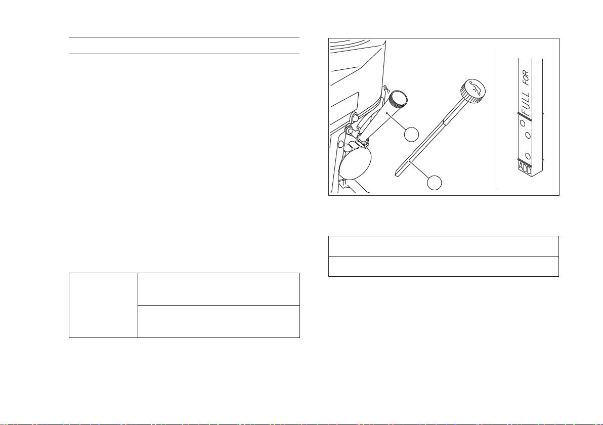
Check the engine oil daily before starting the engine
otherwise shortage of the engine oil may cause
serious damage to the engine such as seizure.
●Place the engine on level surface. Clean area
around the oil gauge before removing it.
●Remove the oil gauge and wipe it with a clean
cloth.
●Pour the oil slowly to "FULL" mark on the oil
gauge.
●Insert the oil gauge into tube WITHOUT
SCREWING IT IN.
●Remove the oil gauge to check the oil level. The
level should be between "ADD" and "FULL" marks.
Do not over ll.
●Install and tighten the oil gauge.
Engine Oil Capacity
1.8 L (1.9 US·qt)
[when oil lter is not removed]
FS730V
2.0 L (2.1 US·qt)
[when oil lter is removed]
PREPARATION 15
B
A
A. Oil Gauge
B. Tube
NOTICE
The engine is shipped with out engine oil.
Page 18
16 STARTING
STARTING
Start Engine
DANGER
Exhaust gas contains carbon monoxide, a
colorless, odorless poisonous gas. Inhaling
carbon monoxide can cause serious brain
injury or death. DO NOT run the engine in
enclosed areas. Operate only in a wellventilated area.
WARNING
Engine exhaust may ignite combustible
materials and cause a re.
Keep the area around the exhaust outlet
clear. Locate the unit so that the exhaust
outlet points toward an open area and is
located at least one meter (3.3 feet) from any
obstructions.
NOTE
○Be aware of the following in order to start the
engine easily in cold weather.
○Use proper oil for expected temperature (See
FUEL AND OIL RECOMMENDATIONS chapter).
Use fresh gasoline.
○Protect the engine or the equipment from direct
exposure to weather when not in operation.
○Before starting the engine, disconnect all possible
external loads.
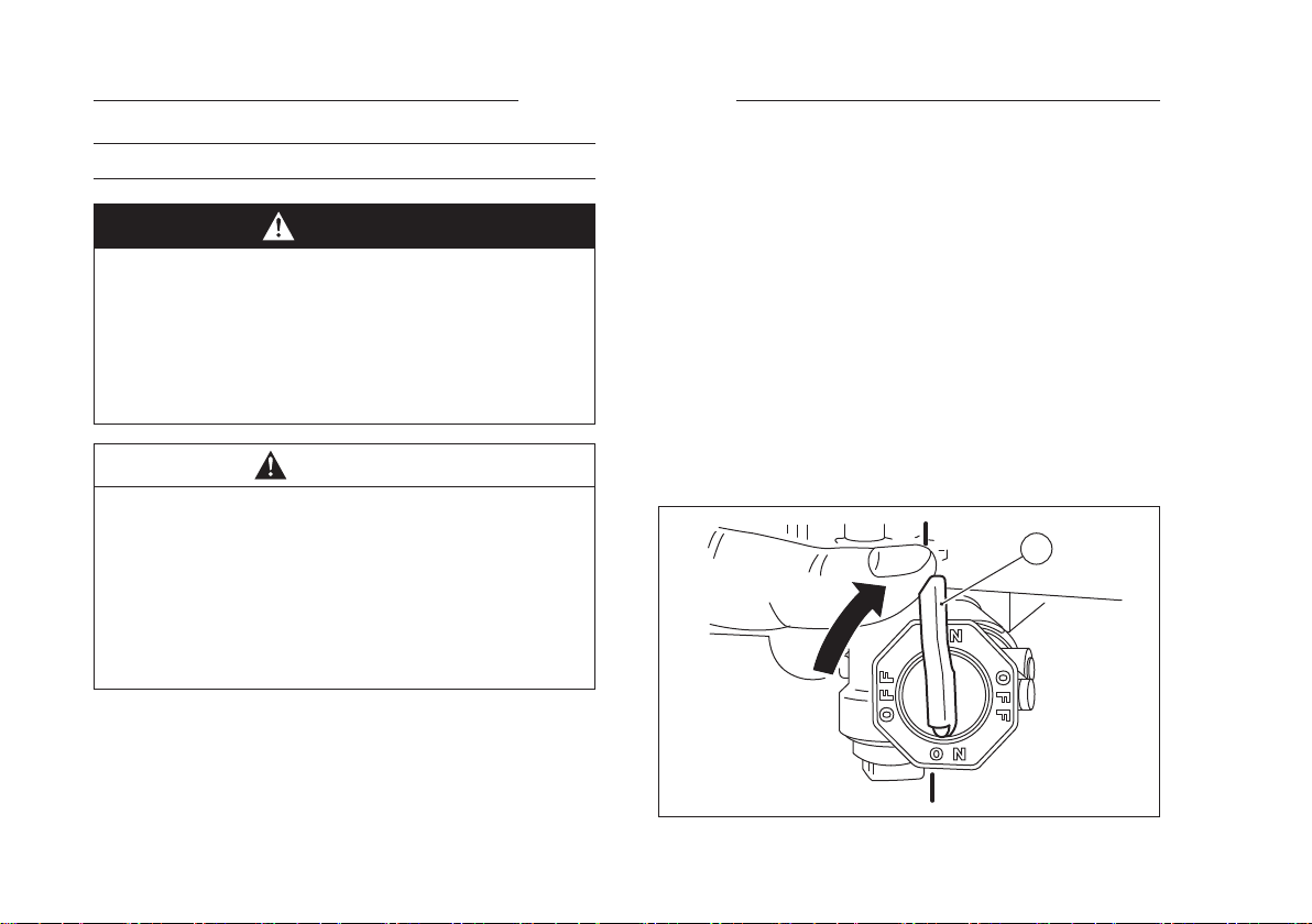
●Open the fuel valve on the equipment.
●Put the engine switch key into the engine switch
and turn to the ON or RUN position.
●Turn the switch key to the START position on the
equipment. Normally the engine will start within
3 seconds.
ON
ON
A
A. Fuel Valve
Page 19
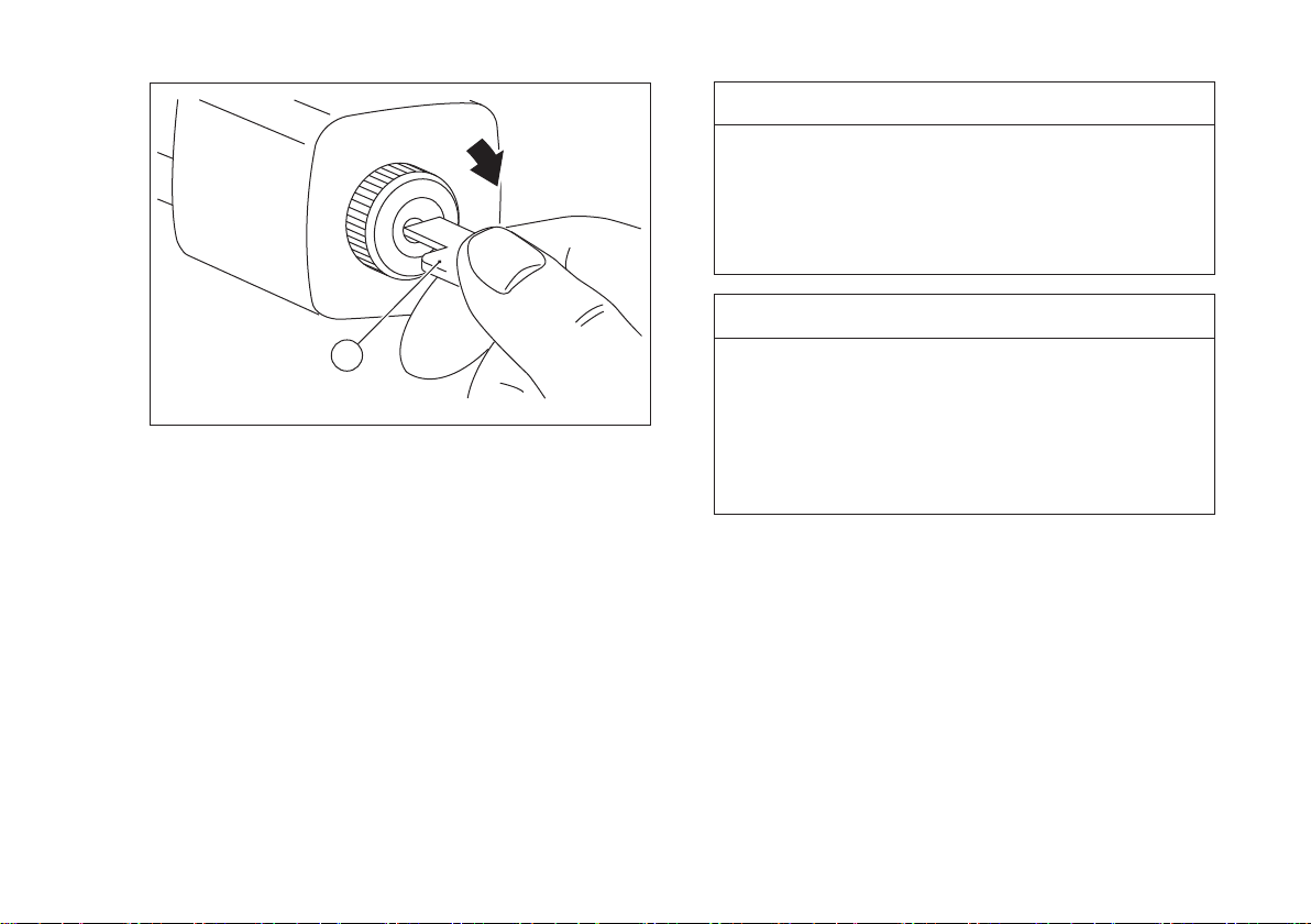
A. Engine Switch Key
STARTING 17
NOTICE
OFF
ON
START
Do not run the electric starter continuously
for more than 5 seconds, otherwise the
battery may discharge quickly. If the engine
does not start right away, wait 15 seconds
and try again.
NOTICE
A
Whenever you start engine, make sure
warning light is not illuminated after engine
starts.
If warning light comes on, stop engine
immediately and check oil level (If
equipped).
Page 20

18 OPERATING
OPERATING
Warming Up
To warm up the engine, run it for 3 to 5 minutes
with the throttle lever in the same load position
before putting the equipment under load. Then,
move the throttle lever on the equipment to its
"FAST "position.
NOTICE
Allow engine to warm up sufciently (3 to
5 minutes at idle) before applying a load.
This will allow oil to reach all engine parts,
and allow piston clearance to reach design
specications.
NOTICE
While warming up the engine, make sure the
warning light (oil pressure) on dash is not
on. The warning light must not be illuminated
during engine operation (if equipped).
Page 21

Engine Inclination
This engine will operate continuously at angles up
to 25° in any direction.
Refer to the operating instructions of the equipment
this engine powers. Because of equipment design or
application, there may be more stringent restrictions
regarding the angle of operation.
NOTICE
Do not operate this engine continuously
at angles exceeding 25° in any direction.
Engine damage could result from insufcient
lubrication.
OPERATING 19
Page 22
20 STOPPING
STOPPING
Stopping the Engine
Ordinary Stop
●Move throttle lever to "SLOW" position.
●Lower the engine speed to the idle speed. Keep
running at the idle speed for about one minute.
NOTICE
Engine damage can occur from run-on or
after-burning if engine is stopped suddenly
from high speed loaded operation. Reduce
engine speed to idle for one minute before
shutting engine off.
●Turn the engine switch or the switch key to "OFF"
position.
Emergency Stop
●Immediately turn the engine switch or the switch
key to "OFF" position.
●Close the fuel valve on the equipment.
WARNING
Leaving the equipment with the key hanging
in the ignition can allow operation by
someone who does not know how to operate
it. It may cause serious accident with injury.
Always remove the key from unattended
equipment.
Page 23

ADJUSTMENT
Engine Speed Adjustment
NOTE
○Do not tamper with the EFI system setting to
increase the engine speed. Every EFI system is
adjusted at the factory.
○If any adjustment is necessary, see your
authorized Kawasaki engine dealer to perform the
adjustment.
ADJUSTMENT 21
Page 24
22 MAINTENANCE
MAINTENANCE
Maintenance, replacement, or repair of the emission control devices and systems may be performed by any
nonroad engine repair establishment or individual.
Periodic Maintenance Chart
WARNING
Prevent accidental starting during engine service by removing the spark plug caps.
NOTE
○The service interval scan be used as a guide. Service more frequently as necessary by operating conditions.
Page 25
MAINTENANCE 23
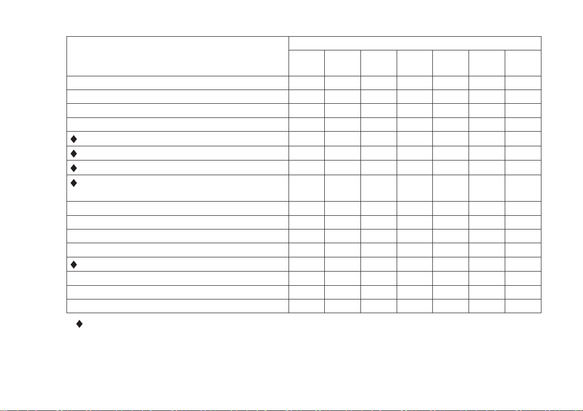
INTERVAL
MAINTENANCE
Check and add engine oil.
Check for loose or lost nuts and screws. ●
Check for fuel and oil leakage. ●
Check battery electrolyte level. ●
Check or clean air inlet screen. ●
Clean air cleaner foam element. ●
Clean air cleaner paper element. ●
Clean dust and dirt from cylinder and cylinder
head ns.
K
Tighten nuts and screws. ●
Change engine oil. ● ●
Clean and regap spark plugs. ●
Change oil lter. ●
Replace air cleaner paper element. ●
K Clean combustion chamber. ●
K Check and adjust valve clearance. ●
K Clean and lap valve seating surface. ●
Daily
●
First
8 hr.
Every
25 hr.
Every
100 hr.
●
Every
200 hr.
Every
250 hr.
Every
300 hr.
: Service more frequently under dusty conditions.
K: Service to be performed by an authorized Kawasaki dealer.
Page 26
24 MAINTENANCE
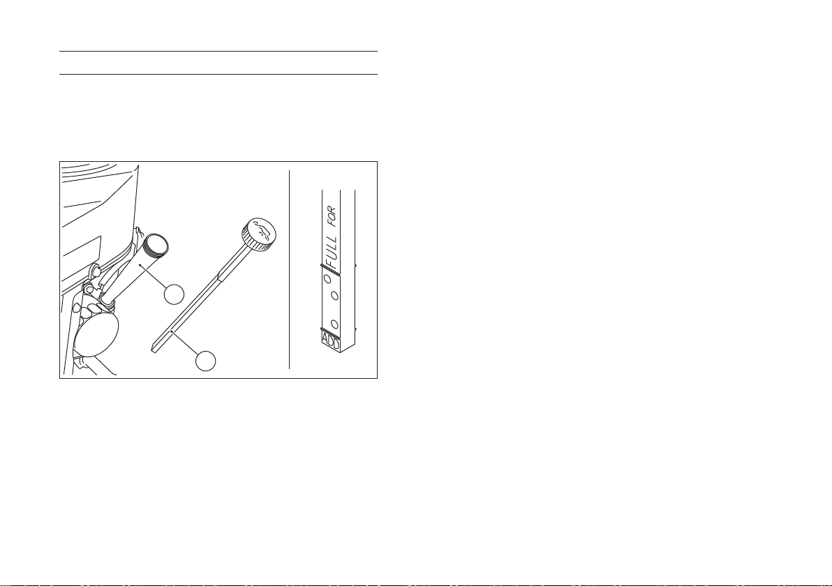
Oil Level Check
Check the oil level daily and before each time of
operation. Be sure the oil level is maintained. See
PREPARATION chapter.
B
A
A. Oil Gauge
B. Tube
Page 27
MAINTENANCE 25
Oil Change
Change oil after first 8 hours of operation.
Thereafter change oil every 100 hours.
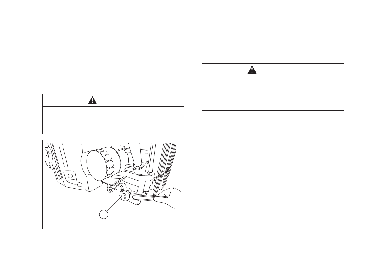
●Run the engine to warm oil.
● Be sure the engine (equipment) is on level surface.
●Stop the engine.
●Remove the oil drain plug and drain the oil into a
suitable container while engine is warm.
WARNING
Hot engine oil can cause severe burns.
Allow engine temperature to drop from hot to
warm level before draining and handling oil.
●Install the oil drain plug.
●Remove the oil gauge and rell with fresh oil (See
FUEL AND OIL RECOMMENDATIONS chapter).
●Check the oil level (see PREPARATION
chapter).
WARNING
Engine oil is a toxic substance. Dispose
of used oil properly. Contact your local
authorities for approved disposal methods
or possible recycling.
A. Oil Drain Plug
A
Page 28
26 MAINTENANCE
Oil Filter Change
●Change the oil lter every 200 hours of operation.
WARNING
Hot engine oil can cause severe burns.
Allow engine temperature to drop from hot to
warm level before attempting to remove oil
lter.
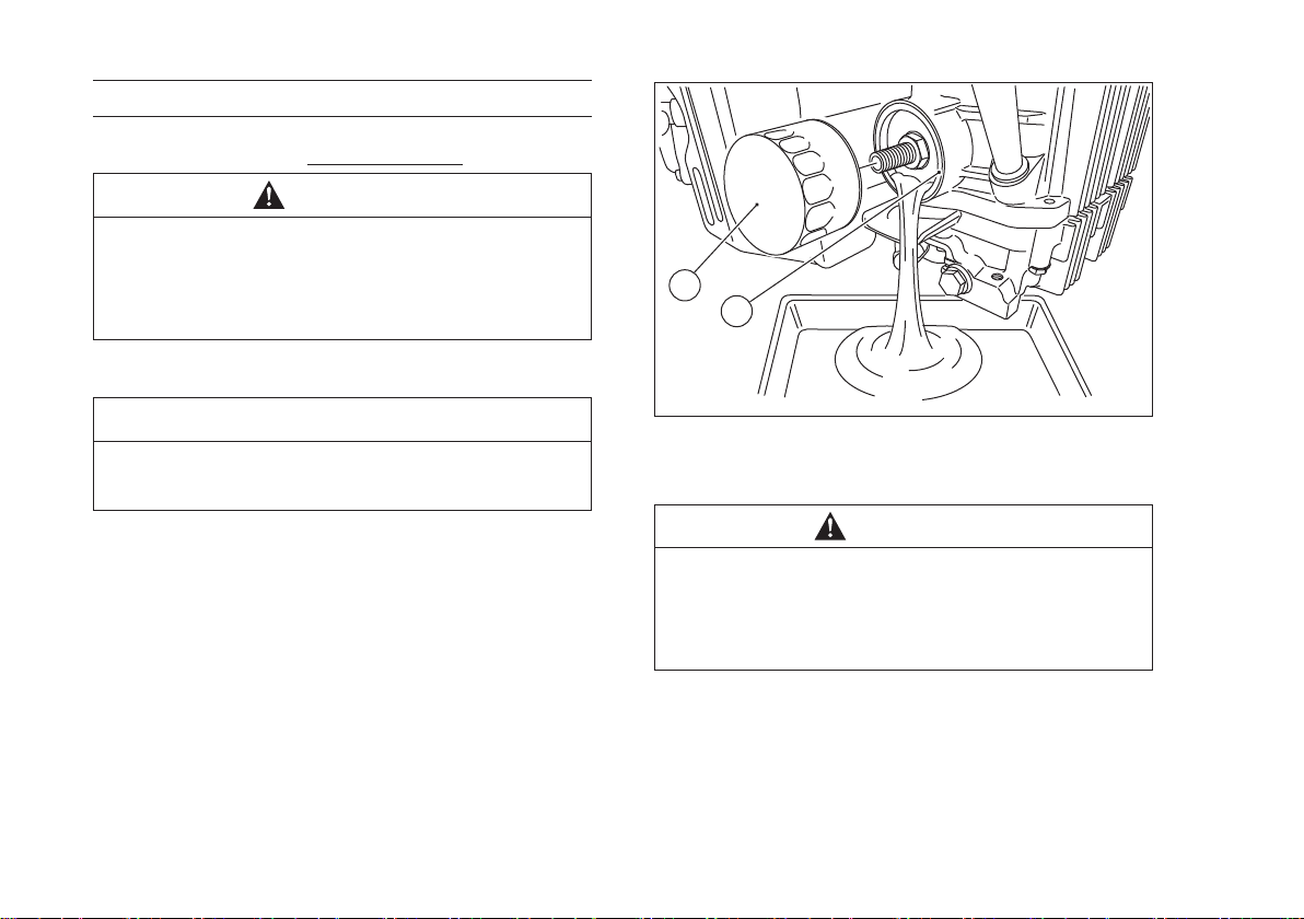
●Drain the engine oil into a suitable container.
A
B
NOTICE
Before removing the oil lter, place suitable
pan under lter connection.
●Rotate the oil lter counterclockwise to remove it.
●Coat a lm of clean engine oil on the seal of new
lter.
●Install new lter rotating it clockwise until the seal
contacts the mounting surface. Then rotate the
lter 3/4 turn more by hand.
●Supply engine oil as specied.
●Run the engine for about 3 minutes, stop the
engine, and check any oil leakage around the
lter.
●Add oil to compensate for oil level drop due to oil
lter capacity (see PREPARATION chapter).
A. Oil Filter
B. Mounting Surface
WARNING
Engine oil is a toxic substance. Dispose
of used oil properly. Contact your local
authorities for approved disposal methods
or possible recycling.
Page 29
MAINTENANCE 27
Air Cleaner Service
NOTICE
To prevent excessive engine wear, do not
run the engine with the air cleaner removed.
Foam Element
Clean the foam element every 25 hours.
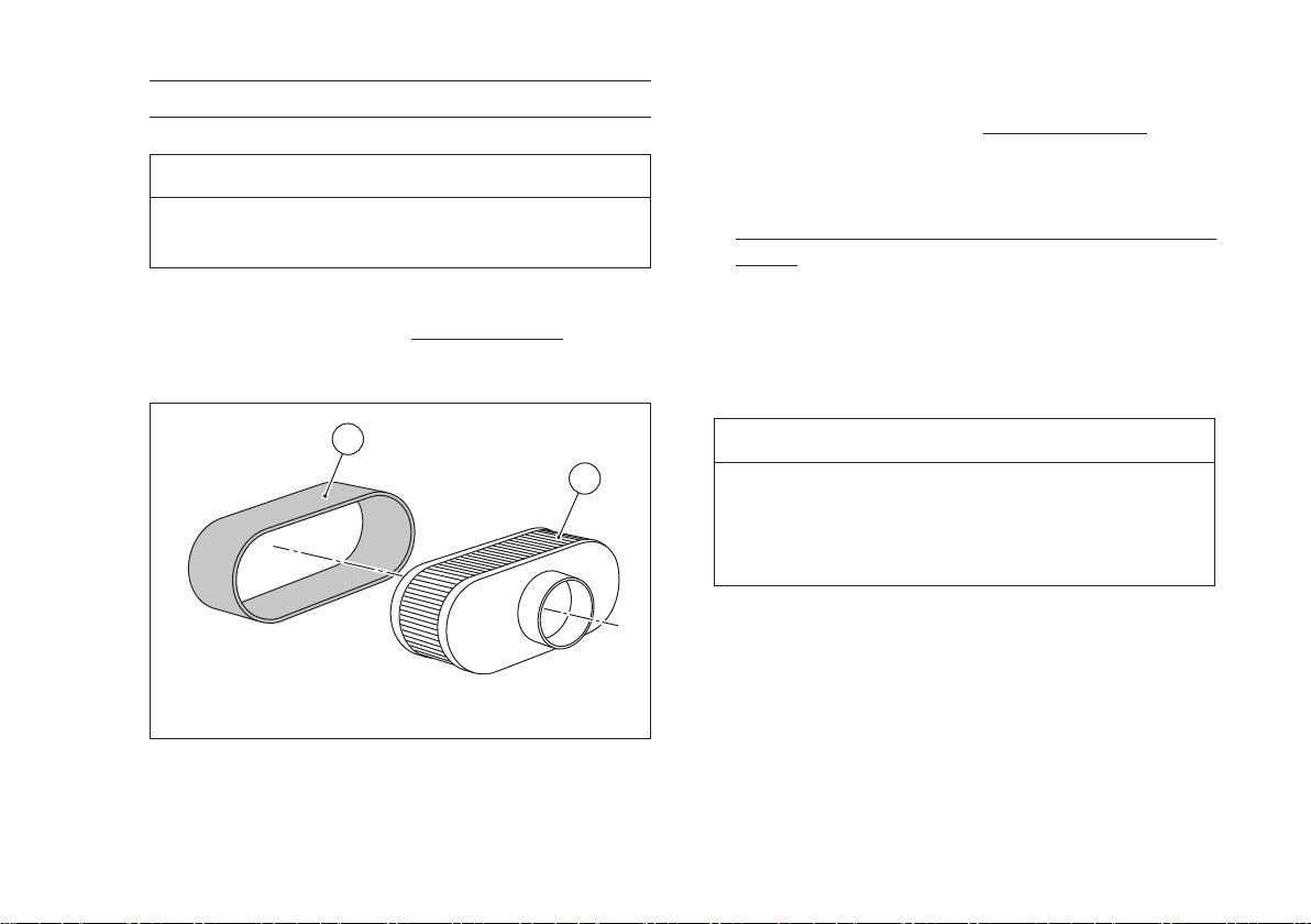
●Wash the foam element in detergent and water,
and dry it thoroughly.
A
B
Paper Element
Clean the paper element every 100 hours.
●Clean the paper element by tapping gently to
remove dust. If very dirty, replace the paper
element with a new one.
Replace with a new paper element yearly or 200
hours. Whichever comes rst.
NOTE
○Operating in dusty condition may require more
frequent maintenance than above.
NOTICE
Do not wash paper element.
Do not oil foam or paper element.
Do not use pressurized air to clean paper
elements.
A. Foam Element
B. Paper Element
Page 30
28 MAINTENANCE
B
A
D
E
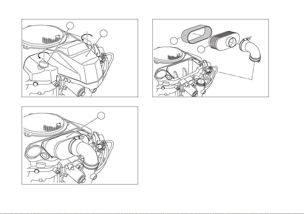
A. Air Cleaner Cover
B. Knob
C
C. Air Cleaner
D. Foam Element
E. Paper Element
Page 31
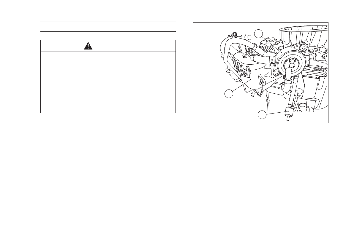
Fuel Filter and Fuel Pump Service
WARNING
Improper use of solvents can result in re or
an explosion.
Do not use gasoline or low ash-point
solvents to clean the fuel lter and/or the fuel
pumps.
Clean only in a well ventilated area away
from sources of sparks or ame, including
any appliances with a pilot light.
●The fuel lter can not be disassembled. If the fuel
lter gets clogged, replace it with a new one.
●The fuel pumps can not be disassembled. If the
fuel pump fails, replace it with a new one.
MAINTENANCE 29
C
B
A
A. Fuel Filter
B. Fuel Pump (Electric)
C. Fuel pump (Pulse)
Page 32
30 MAINTENANCE
Spark Plug Service
WARNING
Engines can become extremely hot during
normal operation. Hot engine components
can cause severe burns. Stop the engine and
allow it to cool before checking spark plugs.
Clean or replace the spark plugs and reset the
gap every 100 hours of operation.
●Disconnect the spark plug caps from the spark
plugs and remove the spark plugs.
●Clean the electrodes by scraping or using a wire
brush to remove carbon deposits.
●Inspect for cracked porcelain, other wear or
damage. Replace the spark plug with a new one
if necessary.
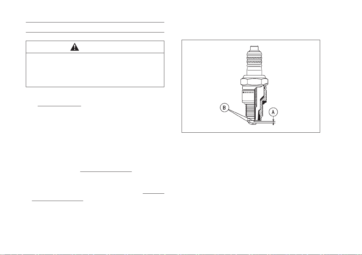
●Check the spark plug gap and reset it if necessary.
The gap must be 0.75 mm (0.030 in). To change
the gap, bend only the side electrode, using a
spark plug tool.
●Install and tighten the spark plugs to 22 N·m
(2.2 kgf·m, 16 ft·lb).
●Fit the spark plug caps on the spark plugs
securely.
●Pull up the spark plug caps lightly to make sure of
the installation of the spark plug caps.
RECOMMENDED SPARK PLUG
NGK..................................BPR4ES
A. Spark Plug Gap
B. Electrodes
Page 33
MAINTENANCE 31
Fuse Service
A blade type fuse is in the fuse case located on
the side of the engine.
If a fuse blows during operation, inspect the
cause, and then replace it with a new fuse of proper
amperage.
Fuse Rating 30-amp Automotive Blade-type
MIL (Malfunction Indicator Light)
The equipment has a MIL to indicate malfunction
of the EFI system.
When the ECU of the engine detects the EFI
system trouble, MIL illuminates.
If the MIL illuminates, consult your Kawasaki
dealer.
NOTE
○The ECU also detects overheating of the engine
and lights the MIL. When the MIL illuminates,
conrm if debris or dust is inside the shroud or
fan housing before going to the shop. If there is
debris, remove them and clean inside the shroud
and housing. (refer to Cooling System Cleaning)
Page 34
32 MAINTENANCE
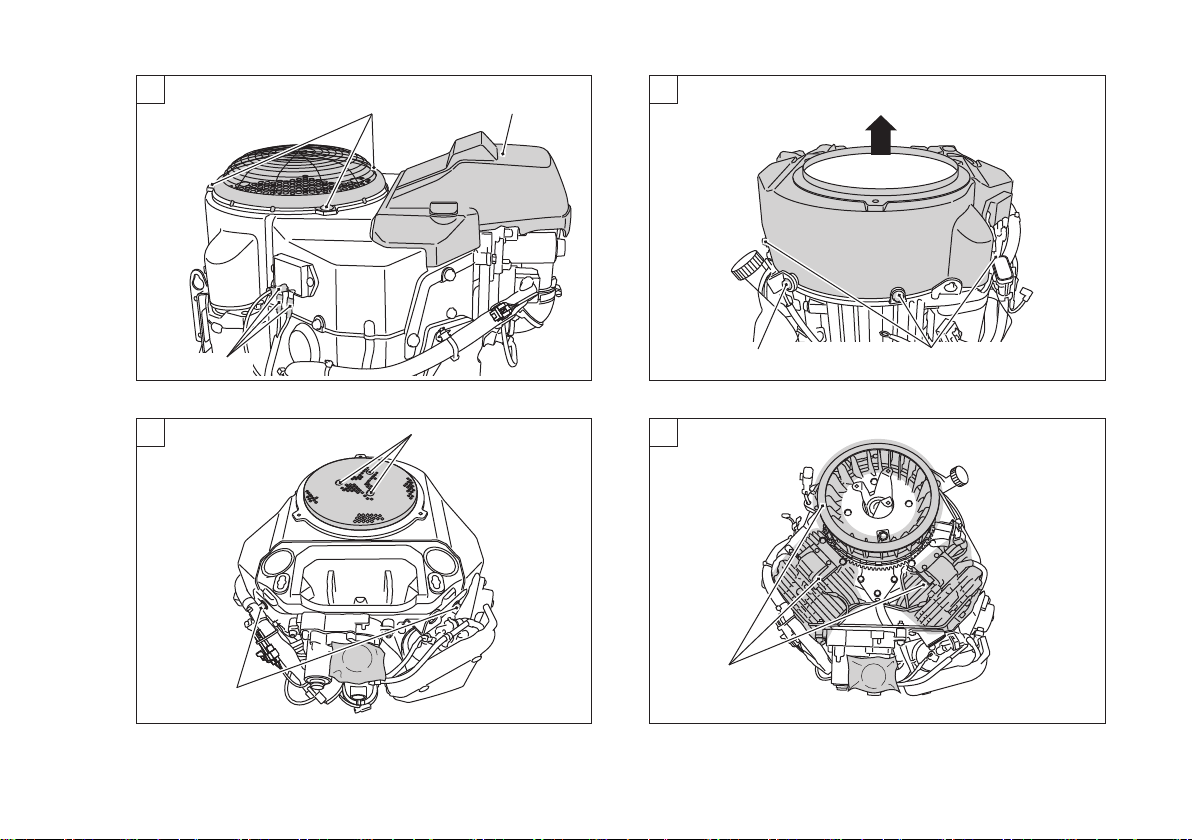
Cooling System Cleaning
Before each operation, check that the air inlet
(rotary) screen is free from grass and debris. Clean
the screen if necessary.
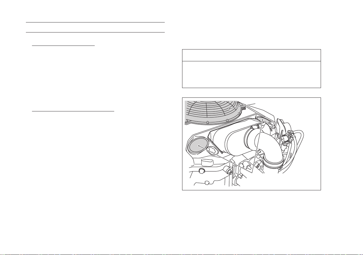
Check dust or debris inside fan housing. To check
inside, remove the air cleaner cover and see inside
from the inspection ports of fan housing. Clean or
blow the dust if needed. If it is difcult to clean the
dust with the ports, remove the fan housing and
clean the dirt completely.
Every 100 hours of operation, check and clean
the cooling ns and the inside of engine shrouds
to remove grass, chaff or dirt clogging the cooling
system and causing overheating.
Cleaning procedures are as below.
●Remove the air cleaner cover and cleaner element
assembly.
●Disconnect the voltage regulator wires.
●Loose the screws and remove the air inlet guard.
●Remove torx bolts and remove the air inlet screen.
●Loose three bolts and remove three bolts at the
fan housing.
●Remove the fan housing.
●Clean and blow out the dust or debris from the
cooling fan and the engine body.
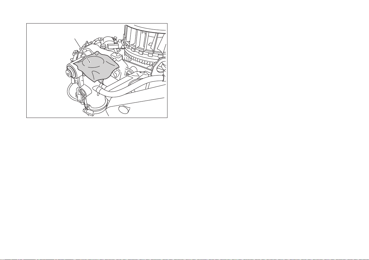
NOTE
○Cover the inlet port of the throttle body to keep
dust off the port.
NOTICE
Do not run engine before all cooling system
parts are reinstalled to keep cooling and
carburetion as intended.
Check the inlet screen.
Check and see dust
from the inspection ports.
Page 35
MAINTENANCE 33
1
2
3
4
Remove Remove
Disconnect
Remove torx bolt
and screen.
Loose bolts.
Clean and blow
dust or debris.
Remove fan housing.
Remove bolts.Loose bolt.
Page 36
34 MAINTENANCE
Cover the intake port.
Page 37
STORAGE
STORAGE 35
Engine Storage Procedure
When not operating your Kawasaki engine more
than 30 days, add fuel stabilizer to fuel tank and run
engine for 5 minutes then drain the fuel tank.
After drain the fuel tank, run the engine at low idle
until engine stalled.
WARNING
Gasoline is extremely ammable and can be
explosive under certain conditions.
Drain fuel before storing the equipment for
extended periods.
Drain gasoline in a well ventilated area
away from any source of ame or sparks,
including any appliances with a pilot light.
Store gasoline in an approved container in
safe location.
WARNING
Gasoline is a toxic substance. Dispose
of gasoline properly. Contact your local
authorities for approved disposal methods.
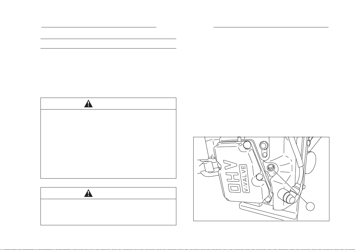
●Remove the spark plugs and pour approx 1-2 mL
(0.06-0.1 cu in.) of engine oil through the spark
plug holes then screw the spark plugs in after
cranking the engine a few times. Slowly crank the
engine until you feel the compression then leave
it there. This traps the air inside the cylinders and
prevents rust inside the engine.
●Wipe the body with oily cloth.
●Wrap the engine with plastic sheeting and store it
in a dry place.
●Change engine oil for next use after period of
storage. (Refer to MAINTENANCE chapter for Oil
Change section).
A
A. Spark Plug Hole
Page 38
36 TROUBLESHOOTING GUIDE
TROUBLESHOOTING GUIDE
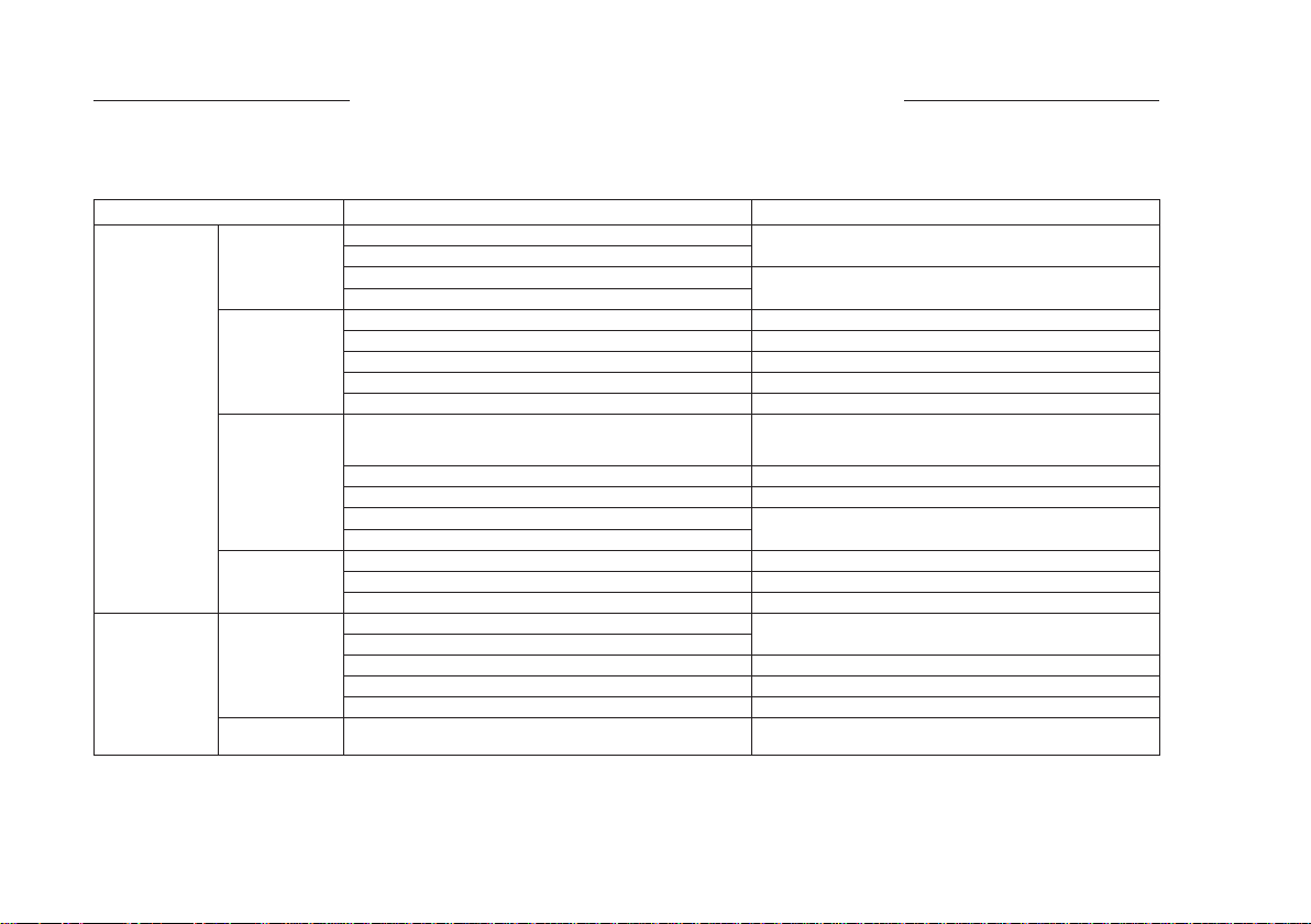
If the engine malfunctions, carefully examine the symptoms and the operating conditions, and use the table
below as a guide to trouble shooting.
Symptom Probable Cause Remedy
Engine won't
start or output
is low
Low output Engine
K : Service to be performed by an authorized Kawasaki dealer.
M : For Control Panel Switch Type, move the throttle lever on the equipment away from it slow speed end to turn the engine
switch to "START" position.
Insufcient
compression
No fuel to
combustion
chamber
Spark plugs
fouled by fuel
No spark or
weak spark
overheats
Engine speed
won't increase
Faulty pistons, cylinders, piston rings, and head gaskets K
Faulty valves
Loose spark plugs Tighten properly
Loose cylinder head bolts
No fuel in fuel tank Fill fuel tank
Fuel valve is not in "ON" position. Open fuel valve lever.
Clogged fuel lter or tube Change fuel lter or fuel tube
Clogged air vent in tank cap Clean fuel tank cap
Faulty fuel system K
Over-rich fuel/air mixture Rotate engine with spark plugs removed to discharge
Clogged air cleaner Clean
Faulty fuel system K
Incorrect grade/type of fuel Change fuel
Water in fuel
Faulty spark plugs Replace spark plugs
Faulty ignition coils K
Engine switch is in "OFF" position Turn engine switch to "START" position (See M)
Clogged air cleaner Clean
Air inlet screen or cooling air path clogged with dirt
Insufcient engine oil Replenish or change oil
Carbon build-up in combustion chamber K
Poor ventilation around engine Select a better location
Faulty E-governor K
excess fuel.
Cleans park plugs.
Page 39

ENVIRONMENTAL PROTECTION 37
ENVIRONMENTAL PROTECTION
To help preserve the environment, properly discard used batteries, oils and uids, or other engine components
that you might dispose of in the future.
Consult your authorized Kawasaki dealer or local environmental waste agency for their proper disposal
procedure. This also applies to disposal of the entire engine at the end of its life.
Page 40
38 SPECIFICATIONS
SPECIFICATIONS
FS730V EFI
Type Air-cooled, 4-stroke OHV 4Valves, V-twin cylinder, gasoline engine
Bore × Stroke 78 × 76 mm (3.07 × 2.93 in.)
Displacement 726 mL (44.30 cu.in.)
Ignition System Inductive ignition
Direction of rotation Counterclockwise facing the PTO Shaft
Starting system Electric starter
Dry weight : kg (lbs) 46.5 kg (102.4 lbs)
NOTE
○Specications are subject to change without notice.
○Dry weight excludes that of the fuel tank and the mufer.
Page 41
NOTE
1. ILLUSTRATIONS OF CONNECTOR
TERMINALS ARE FOR HARNESS SIDE.
WIRE COLORS
WIRE COLOR
BLACK
BLUE
BROWN
GRAY
GREEN
ORANGE
SYMBOL
BK
BL
BR
GR
BN
O
WIRE COLOR
PINK
RED
TAN
VIOLET
WHITE
YELLO
SYMBOL
P
R
T
V
W
Y
POWER TO PTO CLUTCH
FUSED POWER LINE
TO PTO CLUTCH
MAIN RELAY
10A ATO/ATC
FAST-ACTING FUSE
BLADE RELAY
ANALOG INPUT +
RANGE: 0-5VDC SIG
HALL EFFECT PREFERRED -
+12V SIGNAL FROM
MACHINE TO ENGAGE
PTO CLUTCH
MIL LIGHT
+12V
OPTIONAL INPUT:
OIL PRESSURE LIGHT
OR HOUR METER
FUEL RELAY
2A ATO/ATC
FAST-ACTING FUSE
KEYED +12VDC THAT
IS INDEPENDENT OF
OPERATOR PRESENCE
SWITCH.
CAN LOW
CAN HIGH
+12V TO RUN
OPEN TO KILL
(OPS SIGNAL)
10 PIN CONNECTOR
KEY SWITCH
-
A B C D E
OFF
RUN
START
KEY OPERATION
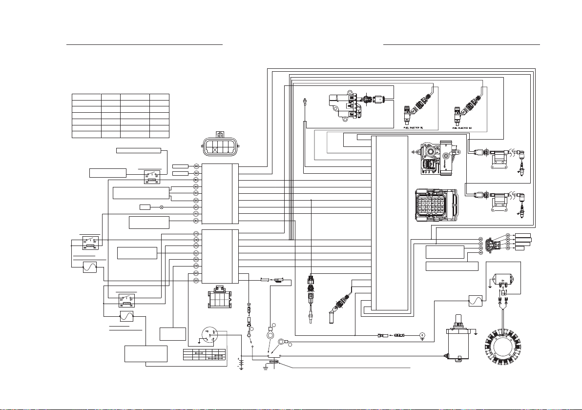
WIRING DIAGRAM
GROUND TO
ENGINE BLOCK
380
370 360
350
340
390
310
320
330
BL
CAN_LOW
380
Y/B R
CAN_HIGH
390
GN
360
BLADE_RLY_CNTL
MAIN_RLY_CNTL
8 PIN CONNECTOR
FUEL_RLY_OUT
MAIN_RLY_OUT
FUEL_RLY_CNTL
BLADE_RLY_SIG
KEY +12V SIG
HTIS_POWER
HTIS_SIGNAL
HTIS_GND
MIL_GND
OPTIONAL_IN
OPS_SW
STARTER
MAIN_RLY_IN
280270 260 250
210220 230 240
BL/W
310
W
330
BK
320
R/P
340
GN/W
370
T
350
BK/W
270
R
280
BR
260
Y/R
210
O
250
Y
230
V
240
R
220
(+) 50 60 GND
B
RED HILEC 400F SLEEVE
16AWG FUSIBLE LINK
A
BATTERY
CYLINDER HEAD
TEMPERATURE
SENSOR
C
SWITCH: PROVIDED BY KMM OR PROCURED BY OEM. IF OEM
PROVIDES, WIRES A, B, AND C MAY NEED LENGTH CHANGES.
ELECTRIC FUEL PUMP
(+) 170
180 (-)
CRANKSHAFT
POSITION
SENSOR
Control
110
120
GND
BL/W
GR
W/B
GN/BK
BK
BK
GN
BL/W
W
BK
R/P
GN/W
R
BR
Y/R
O
Y
GR/R
V/W
W/R
T
BL
Y/BR
BK/W
BK
G4
IGN #2 SIGNAL
IGN #1 SIGNAL
H4
INJ #2 SIGNAL
H1
INJ #1 SIGNAL
F1
POWER_GND
G3
POWER_GND
G2
BLADE_RLY_CNTL
E4
HTIS_POWER
E1
HTIS_SIGNAL
B4
HTIS_GND /CHTS_GND
E2
MIL_GND
F2
MAIN_RLY_CNTL
F4
ECU
VBR (12V)
G1
FUEL_RLY_CNTL
H2
BLADE_RLY_SIG
C1
KEY_12V_SIG
E3
OPS_SW
C2
CHTS (+)
D4
CPS (-)
A2
CPS (+)
A1
OPTIONAL_IN
B1
CAN_LOW
A3
CAN_HIGH
A4
WIRING DIAGRAM 39
GN/BK
R
Signal
70
80
Power
ECU
ECU Connector
(Harness Side)
CONNECTED TO
ENGINE GROUNDING
RING VIA SPLICE
CONNECTED TO 280 OF 8 PIN
CONNECTOR VIA SPLICE
GROUND
TO ENGINE
BLOCK
STARTER
Signal
90
W/BK
100
Power
GR
R
BL/W
R
30A FUSE
R
Signal
140
130
Power
IGNITION COIL #1
Signal
160
150
Power
IGNITION COIL #2
DIAGNOSTIC
REGULATOR
VOLTAGE
STATO R
CYL. #1
CYL. #2
CAN LOW
CAN HIGH
GROUND
+12V
Page 42

Page 43

Page 44
WARNING
The engine exhaust from this product
contains chemicals known to the
State of California to cause cancer,
birth defects or other reproductive
harm.
For repair / warranty assistance please contact
your local Kawasaki Authorized Dealer,
email: [email protected] or
call toll-free 1-877-364-6404
Part No. 99920-2284-01
Printed in Japan
GB
 Loading...