

Page 1

VULCAN 1600 NOMAD
VN1600 CLASSIC TOURER
Motorcycle
Assembly & Preparation
Manual
Page 2
Foreword
In order to ship Kawasaki vehicles as efficiently as possible, they are partially disassembled before crating. Since some of the most
commonly removed parts have a direct bearing on a vehicle’s reliability and safety, conscientious pre-sale assembly and preparation becomes extremely important. Good setup procedures can prevent needless warranty claims
and give customers a greater sense of confidence in Kawasaki and their Kawasaki Dealers.
This Assembly and Preparation Manual explains step by step procedures of the following
items for all Kawasaki motorcycles.
1. Uncrating
2. Assembly
3. Preparation
The selling dealer assumes sole responsibility for any unauthorized modifications prior to
sale. Refer to your Service Binder for any Service Bulletins specifying Factory Directed Modifications (Special Claims) which must be performed before the vehicle is ready for sale.
Whenever you see the following symbols
heed their instructions! Always follow safe
operating and maintenance practices.
WARNING
This warning symbol identifies special
instructions or procedures which, if not
correctly followed, could result in personal injury, or less of life.
CAUTION
This caution symbol identifies special
instructions or procedures which, if not
correctly followed, could result in damage to, or destruction of equipment.
NOTE
żThis note symbol indicates points of particular
interest for more efficient and convenient operation.
Kawasaki Heavy Industries, Ltd. accepts no
liability for any inaccuracies or omissions in this
publication, although every possible measure
has been taken to make it as complete and accurate as possible. All procedures and specifications subject to change without notice.
© 2004 Kawasaki Heavy Industries, Ltd. Nov. 2004 (K)
Page 3

Table of Contents
crating ......................................................................................
Un
Opening Crate ............................................................................. 3
Parts Check ................................................................................. 4
sembly ......................................................................................
As
Handlebar.................................................................................... 8
Throttle Grip and Right Switch Housing ...................................... 8
ront Brake Master Cylinder .......................................................
F
Left Switch Housing..................................................................... 9
Clutch Master Cylinder ................................................................ 10
iring Clamps .............................................................................10
W
Front Fender................................................................................ 11
Front Wheel Installation............................................................... 12
Front Brake Hose Grommets ...................................................... 14
Front and Rear Shift Pedals ........................................................ 14
Front Footboard (Left) ................................................................. 15
Front Guards (Left and Right) ..................................................... 15
Helmet Locks............................................................................... 16
Rear Guards (Left and Right) ...................................................... 16
Backrest Pad ............................................................................... 17
Horn............................................................................................. 17
Choke Knob................................................................................. 18
Rear View Mirrors (Left and Right) .............................................. 18
Windshield................................................................................... 19
License Plate Bracket.................................................................. 21
Rear Reflectors and License Plate Holder .................................. 21
Left Saddlebag ............................................................................ 22
Brake Disc Cleaning .................................................................... 24
Preparation ................................................................................... 24
Battery Service ............................................................................ 24
Front Brake Fluid ......................................................................... 30
Rear Brake Fluid ......................................................................... 31
Clutch Fluid ................................................................................. 32
Rear Shock Absorber .................................................................. 34
Tire Air Pressures........................................................................ 34
Fuel ............................................................................................. 34
Coolant ........................................................................................ 34
Engine Oil (4-stroke) ................................................................... 35
Final Gear Case Oil..................................................................... 36
Throttle Grip and Cable ............................................................... 37
Headlight Aim .............................................................................. 38
Idle Speed Adjustment ................................................................ 38
Rear Brake Light Switch.............................................................. 38
Fastener Check ........................................................................... 40
Standard Torque Table ................................................................ 42
Test Ride the Motorcycle ............................................................. 42
A & P Check List ......................................................................... 42
3
8
9
Page 4

Page 5
Uncrating
Opening Crate
Clear a space about 6 m (20 ft.) square to
•
give yo
Place the crate upright on its base.
•
Remove the cardboard cover.
•
Remov
•
parts box.
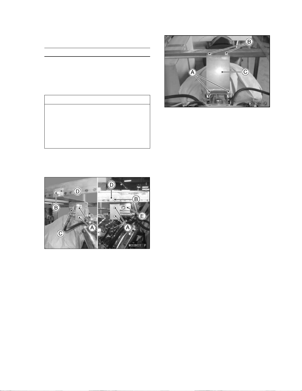
When you remove the crate bracket
from the motorcycle, be careful not to
drop any parts and bracket onto the
fuel tank and other components, and
not to scratch the fuel tank by the crate
bracket. This could damage the fuel
tank or components.
Unscrew the four bolts to remove the front
•
brake and clutch master cylinders.
Remove the two bracket bolts and the crate
•
bracket and discard them.
urself plenty of space to work.
e the handlebar, front wheel, and the
CAUTION
UNCRATI
A. Lower Bolts
B. Upper Bolts
C. Crate Bracket
Take out all the bolts and screws and remove
•
the top and sides of the crate.
NG 3
.Bolts
A
B. Bolt
C. Front Master Cylinder
D. Crate Bracket
E. Clutch Master Cylinder
Unscrew the two lower bolts, and then re-
•
move the two upper bolts and crate bracket.
Discard the bolts and bracket.
Page 6
4 UNCRAT
ING
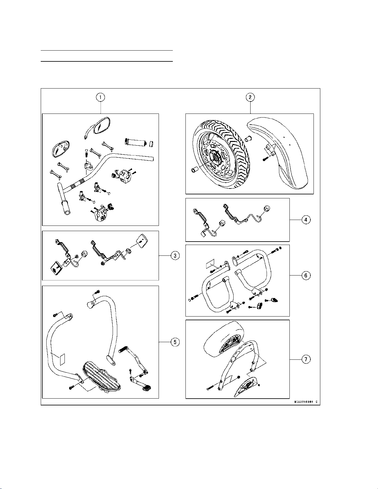
Parts Check
Open the parts box, and check the parts against the illustrations. There may be minor differences
•
between these illustrations and the actual vehicle parts. In the following charts under Remarks, D
= diameter in millimeters, L = length in millimeters, and T = Thickness in m illimeters.
Page 7

UNCRATI
NG 5
No. Part Name
1
Handlebar with Grip
Handlebar Clamp
Clamp Bolt, Socket
Plastic Plug, Clamp Bolt
Throttle Grip
Clamp, Master Cylinder
Clamp Bolt, Master Cylinder, Socket
Plastic Plug, Clamp Bolt
Plastic Clamp, Wiring and Hose
Screw, Switch Housing, LH & RH
Rear View Mirror, LH & RH
Qty
1
2
4 D = 10, L = 23
4 Large
1
2
4 D=6,L=20
4
Small
4 L = 88.5
4 D=5,L=25
2
2 Front Wheel 1
Axle Collar, LH & RH
2 L = 46.5
Front Fender with Brace 1
Socket Bolt, Front Fender
3
For US and CN Models
Brake Hose Clamp, LH & RH
Grommet, Brake Hose
Front Reflector, LH & RH
Flanged Nut, Reflector
4
For other than US and CN Models
Brake Hose Clamp, LH & RH
Grommet, Brake Hose
5
Front Left Footboard Assembly
4 D=8,L=35
2
2
2
2 D=5
2
2
1
Flanged Bolt, Front Footboard, LH 2 D = 10, L = 30
Front Guard, LH & RH
Flanged Bolt, Front Guard
Warning Label, Front Left Guard
Front Shift Pedal
Rear Shift Pedal
Flanged Bolt, Front and Rear Shift Pedals
6
Rear Guard, LH & RH
Flanged Bolt with Washer, Rear Guard, Upper
Socket Bolt, Rear Guard, Lower
Plastic Plug, Socket Bolt, Rear Guard
Flanged Bolt, Rear Guard
Cap Nut, Rear Guard
Helmet Lock 2
Screw with Non-permanent locking agent, Helmet Lock
Warning Label, Rear Left Guard
2
2 D = 10, L = 25
1
US and CN Models Only
1
1
2 D=8,L=25
2
2 D=8,L=30
2 D = 10, L = 50
2 Large
4 D=8,L=35
4 D=8
Located in the left side cover.
2 D=5,L=12
1
US and CN Models Only
7 Backrest Pad 1
Backrest Frame 1
Cover with Mark, Backrest
Cap Nut, Cover
1
4 D=6
Bolt, Backrest Frame 4 D=8,L=50
Nut, Backrest Frame 4 D=8
Remarks
Page 8
6 UNCRAT
ING
* : European Models Only
Page 9

UNCRATI
NG 7
No. Part Name
Qty
Remarks
8 Horn with Bracket 1
Flanged Bolt, Horn 1
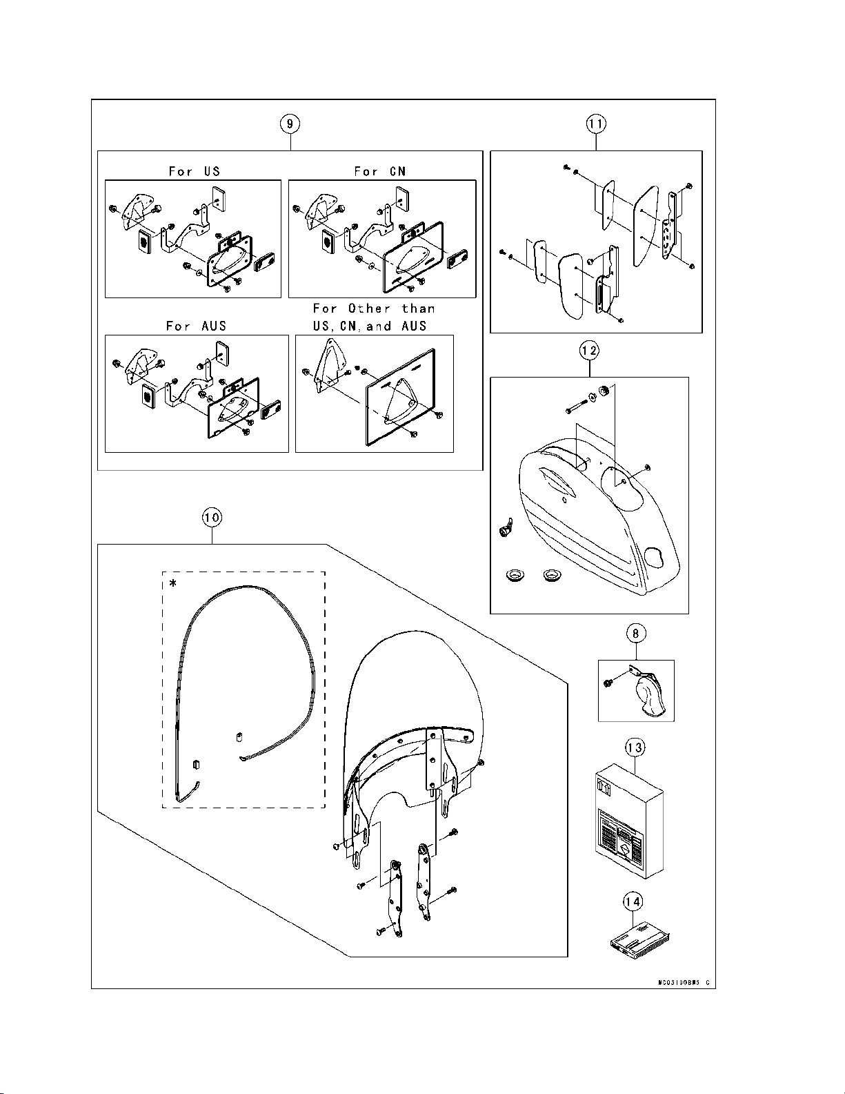
9 Licen
se Plate Bracket
1
Bolt, Bracket, License Plate 2 D=6,L=12
Bracket, Reflector
ector
Refl
1
(US)(CN)(AUS) only
(US)
(CN) only
3
Reflector 1 (AUS) only
Cap Nut, Reflector 3 D = 5, (US)(CN) only
Cap Nut, Reflector 1 D = 5, (AUS) only
Cap Nut, Black, License Plate
Cap Nut, Black, License Plate
Flat Washer, Black, Holder, License Plate 4
4
D = 6, (US) only
2
D = 6, (CN)(AUS)(EUR) only
6.5 × 20 × 1.6, (US) only
D=
Flat Washer, Black, Holder, License Plate 2 D = 6.5 × 20 × 1.6, (CN) (AUS)(EUR) only
Holder, License Plate 1
olt with Flat Washer
B
Bolt with Flat Washer 5
Cap Nut, Holder, License Plate
7 D = 6, L = 14 (US only)
D = 6, L = 14, (CN)(AUS)(EUR) only
3 D=6
10 Windshield Assembly with 1
Center Plate, Outer & Inner (2)
Damper, Center Plate, Outer & Inner (2)
Socket Bolt with Washer, Center Plate (4)
Cap Nut (10)
Vulcan Mark
D=6,L=20
D=6
(1) (US)(CN)(AUS) only
VN1600 Mark (1) (EUR) only
Outer Plate, LH & RH (2)
Inner Plate, LH & RH (2)
Outer Damper, Outer Plate, LH & RH (2)
Inner Damper, Inner Plate, LH & RH (2)
Socket Bolt with Washer, Outer & Inner Plate (6)
D=6,L=25
Sub-windshield (1)
Stay, Windshield, LH & RH (2)
Trim, Windshield 1 L = 1 900, (EUR) only
Clamp, Trim
Socket Bolt, Stay
Bracket, Windshield, LH & RH
2
(EUR) only
4 D=8,L=10
2
Socket Bolt, Bracket, Upper 2 D=8,L=20
Socket Bolt, Bracket, Lower 2 D=8,L=25
11 Outer Plate, Deflector, LH & RH 2
Deflector, LH & RH
Stay, LH & RH
Socket Bolt with Washer
2
2
4 D=6,L=16
Cap Nut 4 D=6
Socket Bolt, Stay 4 D=6,L=16
12 Saddlebag, LH 1
Lock, Saddlebag
1
Located in the left side cover.
Damper, Bottom 2 Large
Damper, Upper 2 D=12
Flanged Collar 2 D = 12, L = 13.1
Flanged Bolt, Saddlebag 2 D=8,L=75
Flat Washer, Saddlebag, Black 4 D = 8.5 × 20, T = 1.6
13
Battery Electrolyte, FTZ16-BS
14
Owner’s Manual
1
1
AUS:
Australian Model EUR: European Model
CN: CN Model US: United States Model
Page 10
8 ASSEMB
LY
Assembly
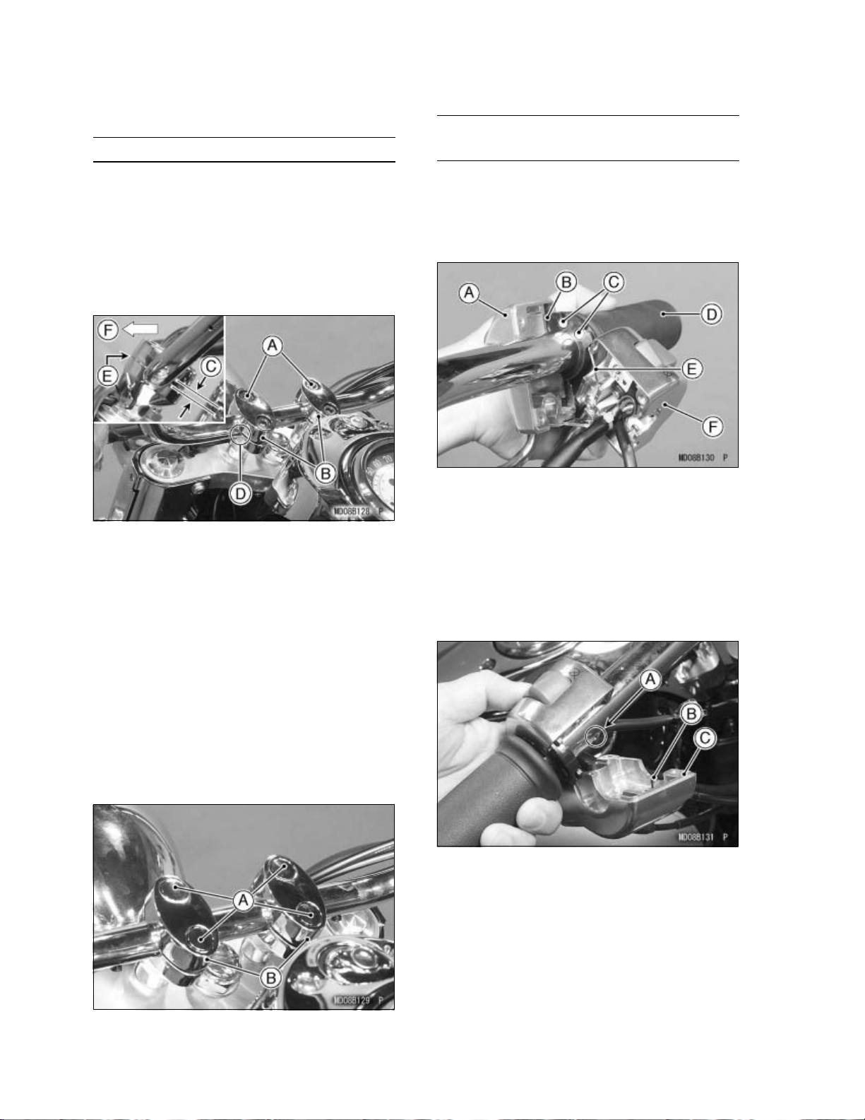
Handlebar
NOTE
żPosition the handlebar clamp on the handle-
bar with the slanted side facing rearward.
e handlebar to match its punched mark
Set th
•
to the rear portion of the lower clamp mating
face and install the upper clamps and bolts (D
=10,L
A. Front Bolts
B. Slanted Side
C.
D. Punched Mark
E. No Gap
. Forward
F
Handlebar Clamp Bolt Tightening
Tighten the front clamp bolts first, and then
•
the rear clamp bolts to the specified torque.
There will be a gap at the rear part of the
clamp after tightening.
Torque:
= 23).
Gap
34 N·m (3.5 kgf·m, 25 ft·lb)
Throttle Grip and Right Switch
Housing
Alignm
Apply a light coat of grease on the exposed
•
portion of the throttle inner cables.
Fit bot
•
socket in the throttle grip.
A. F
B. Throttle Cable (Accelerator)
C. Cable Tips: Apply Grease.
D. Throttle Grip
E. Throttle Cable (Decelerator)
F. Rear Half (Right Switch Housing)
Fit the two halves of the right switch housing
•
so that the pin on the front half fits into the
hole in the handlebar.
ent Pin Type
h throttle cable tips into the nearest
ront Half (Right Switch Housing)
Push the large plastic plugs (4) into the han-
•
dlebar clamp bolts.
A. Plastic Plugs
B. Handlebar Clamps
A. Hole
B. Pin
C. Front Half
Insert the two screws (D = 5, L = 25) and
•
tighten them.
Tighten the holder screw.
•
Check that the throttle grip moves smoothly
•
from full open to close, and the throttle closes
quickly and completely.
Page 11
A. Right Switch Housing
crews (L = 25)
B. S
C. Harness
D. Throttle Cable (Accelerator)
E. Throttle Cable (Decelerator)
F. Holder Screw
Front Brake Master Cylinder
Connect the right switch housing lead con-
•
nectors to the front brake light switch terminals on the front brake master cylinder.
Apply silicone grease or PBC grease to the
•
master cylinder clamp bolts.
Install the front master cylinder with its clamp
•
and the two socket bolts (D = 6, L = 20).
ASSEMBL
Push the small plastic plugs (2) into the mas-
•
ter cylinder clamp bolts.
A. Plastic Plugs
aster Cylinder
B. M
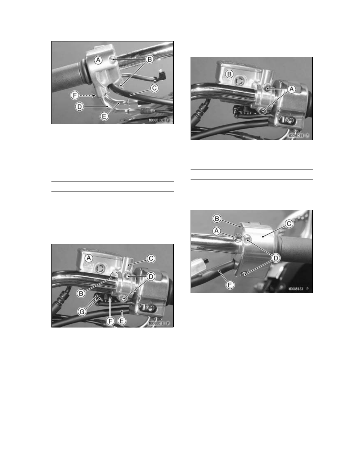
Left Switch Housing
Fit the two halves of the left switch housing
•
together so that the vertical parting line of the
front and rear halves align with the punched
mark on the handlebar.
Y9
A. Front Master Cylinder
B. Punched Mark
C. Clamp
D. Socket Bolts
E. Harness
F. Front Brake Light Switch
G. Connectors and Dust Covers
Position the master cylinder so that the gap
•
between the front and rear master cylinder
clamps aligns with the punched mark on the
handlebar.
Tighten the upper clamp bolt first and then the
•
lower bolt to the specified torque.
Torque:
8.8 N·m (0.90 kgf·m, 78 in·lb)
A. Punched Mark
B. Rear Half (Left Switch Housing)
C. Front Half
D. Screws (L = 25)
E. Harness
Insert the two screws (D = 5, L = 25) and
•
tighten them securely.
Page 12
10 ASSEM
BLY
Clutch Master Cylinder
Apply silicone grease or PBC grease to the
•
master cylinder clamp bolts.
Install the clutch master cylinder with its
•
clamp and the two socket bolts (D = 6, L =
20).
Position the master cylinder so that the gap
•
between the front and rear master cylinder
clamps aligns with the punched mark on the
handlebar.
A. Clamp
B. Clutch Master Cylinder
C. Punched Mark
D. Connector and Dust Cover
E. Starter Lock-out Switch
F. Harness
G. Socket Bolts
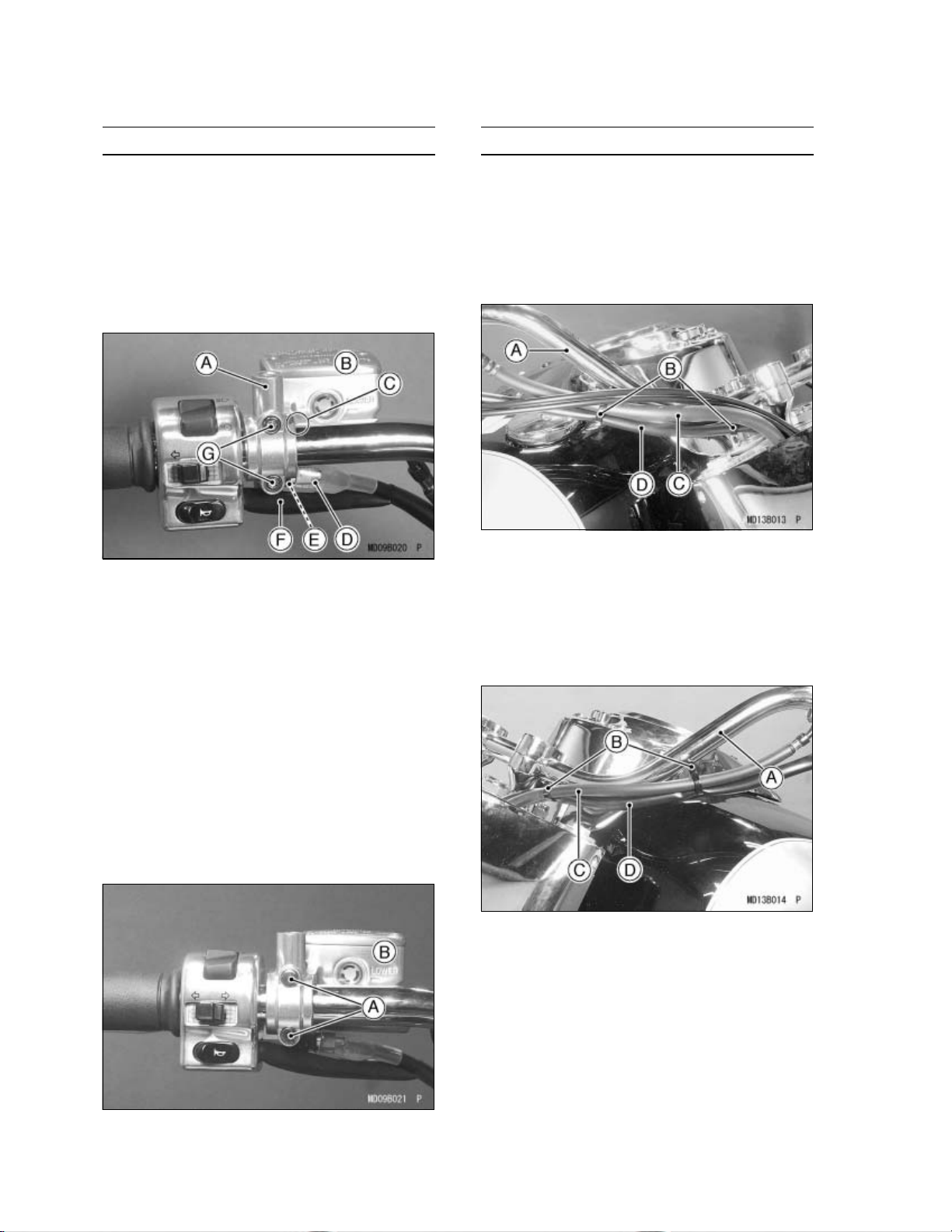
Wiring Clamps
Fasten the front brake hose and the right
•
switch housing harness to the right side of
the handlebar with two plastic clamps.
NOTE
żThe plastic clamp at the inside fastens the
switch harness only.
right
A. Handlebar (Right Side)
lastic Clamps
B. P
C. Front Brake Hose
D. Right Switch Harness
Fasten the clutch hose and the left switch
•
housing harness to the left side of the handlebar with two plastic clamps.
Connect the connector of the left switch hous-
•
ing to the starter lock-out switch on the master
cylinder.
Tighten the upper clamp bolt first and then the
•
lower bolt to the specified torque.
Torque: 11 N·m (1.1 kgf·m, 97 in·lb)
Push the small plastic plugs (2) into the clutch
•
master cylinder clamp bolts.
A. Plastic Plugs
B. Clutch Master Cylinder
A. Handlebar (Left Side)
B. Plastic Clamps
C. Clutch Hose
D. Left Switch Harness
Page 13
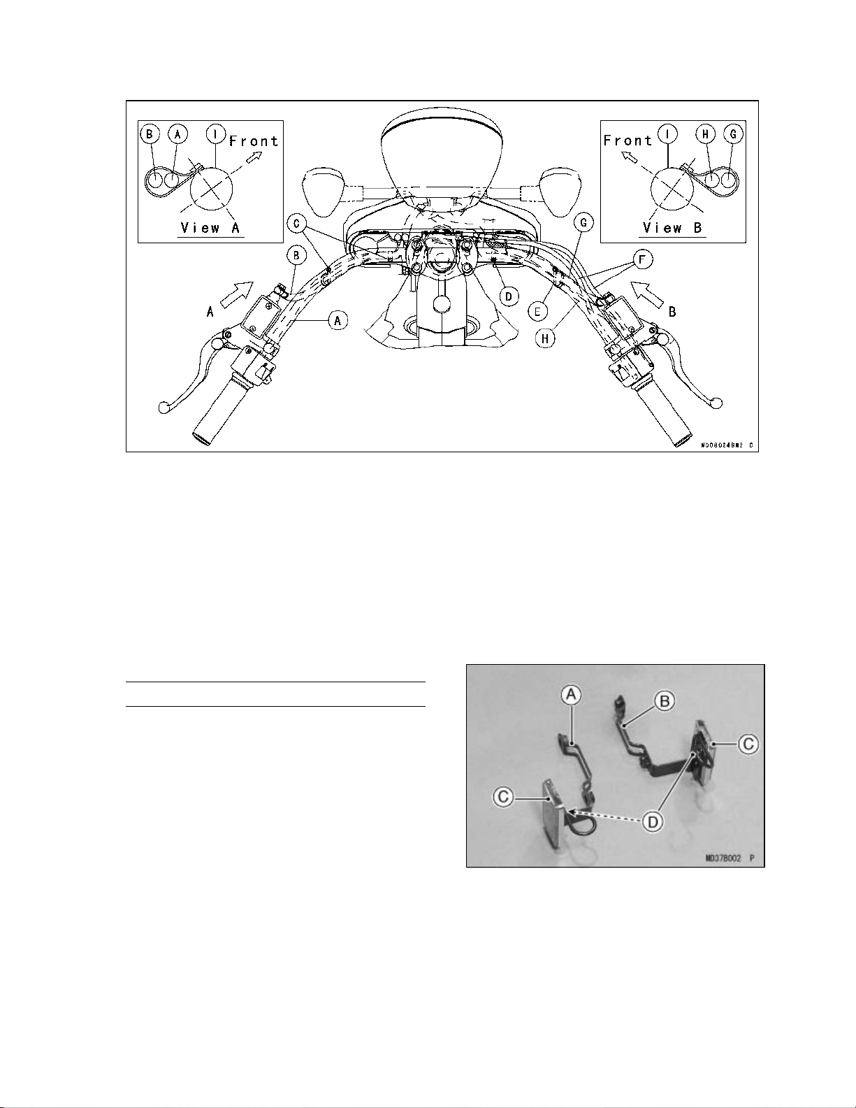
ASSEMBL
Y11
A. Left Switch Lead
B. Clutch Hose
C. Fasten the left switch lead and the clutch hose with two plastic clamps.
D. Fasten the right switch lead with the plastic clamp.
E. Fasten the right switch lead and the brake hose with the plastic clamp.
Throttle Cables
F.
G. Brake Hose
H. Right Switch Lead
Handlebar
I.
Front Fender
Front Reflectors (for US and CN Models
only)
Assemble the front left and right reflectors and
•
the brake hose clamps with the nut (D = 5) on
each.
A. Front Brake Hose Clamp (Left)
B. Front Brake Hose Clamp (Right)
C. Front Reflectors
D. Nuts
Page 14
12 ASSEM
BLY
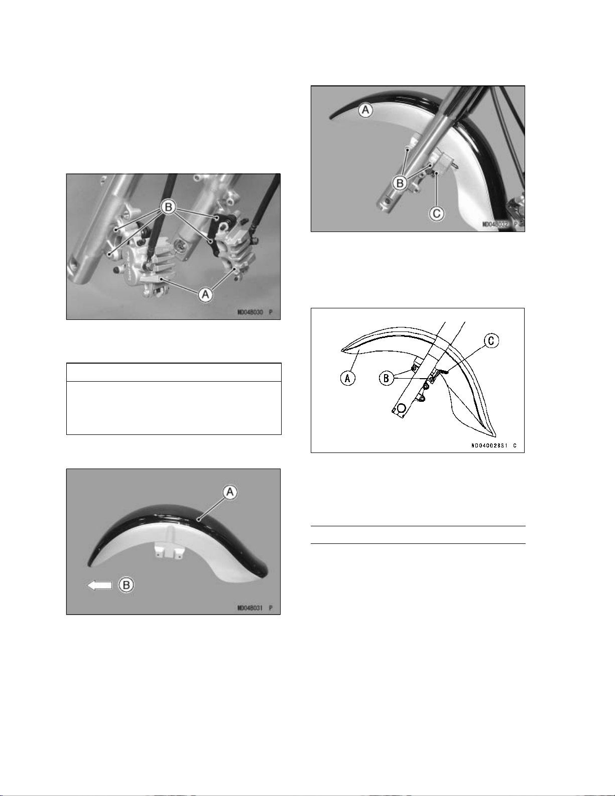
Front Fender Installation
Lift the motorcycle off the crate base and sup-
•
port the motorcycle with a suitable stand or
jack.
Loosen the axle clamp bolts on the right fork
•
leg and remove the front axle.
Loosen the two flanged bolts (D = 10, L = 47)
•
to remove each front brake caliper.
A. Front Brake Calipers
B. Flanged Bolts (D = 10, L = 47)
US and CN Models
A. Front Fender
B. Bolts (D = 8, L = 35)
C. Brake Hose Clamp (Left)
Other than US and CN Models
CAUTION
Do not leave the calipers hanging by
the brake hoses. After removing the
calipers, secure them to the frame using
a suitable band.
Install the front fender with its more rounded
•
end facing forward.
A. Front Fender
B. Forward
Install the front fender on the fork legs, and in-
•
stall the front left and right brake hose clamps
on the inside of the fender with the four bolts
(D = 8, L = 35) and tighten them.
A. Front Fender
B. Bolts (D = 8, L = 35)
C. Brake Hose Clamp (Left)
Front Wheel Installation
Check the wheel rotation mark on the front
•
tire.
NOTE
żThe direction of the wheel rotation is shown
by an arrow on the front tire. Install the wheel
so that the rotation mark coincides with wheel
rotational direction.
Page 15

ASSEMBL
Y13
A. Front Tire
B. Arrow
C. Rotation
Fit the axle collars on both sides of the front
•
wheel hub. The collars are identical.
Put the front wheel assembly between the
•
fork legs.
Insert the front axle from the right side of the
•
wheel and push it completely through.
A. Front Axle
B. Collar (Right)
C. Axle Clamp Bolts (Right)
D. Collar (Left)
A. Pump the fork up and down.
B. Block
Tighten the axle clamp bolts on the right fork
•
leg to the specified torque.
Torque : 29 N·m (3.0 kgf·m, 21 ft·lb)
NOTE
żTighten the two front axle clamp bolts alter-
nately two times to ensure even tightening
torque.
Check the clearance between the right fork
•
leg and the axle collar with a thickness gauge.
There should be about 2.0 mm (0.08 in.) of
clearance. The clearance between 1.05 ~
3.19 mm (0.04 ~ 0.13 in.) is acceptable.
Tighten the front axle to the specified torque.
•
Torque : 108 N·m (11.0 kgf·m, 80 ft·lb)
Temporary install the front brake calipers.
•
Before tightening the axle clamp bolts on the
•
right fork leg, pump the front fork up and down
4 or 5 times to align the right front fork leg and
to seat the front axle. Do not pull the brake
lever when pumping the fork.
NOTE
żDo not apply the front brake during this
process to stop the motorcycle from rolling
forward. Put a block in front of the front wheel
to prevent movement.
A. Right Fork Leg
B. Front Axle
C. Axle Clamp Bolts
D. About 2.0 mm (0.08 in.)
E. Collar (Right)
If the clearance is out of this range, remove
•
the front wheel and check the axle, wheel hub
and other related parts for damage.
Tighten both front brake caliper mounting
•
bolts (D = 10, L = 47) to the specified torque.
Torque : 34 N·m (3.5 kgf·m, 25 ft·lb)
Page 16

14 ASSEM
BLY
Check the front brake.
•
A. Front Brake Caliper (Left)
lts (D = 10, L = 47)
B. Bo
WARNING
Do not attempt to ride the motorcycle until a full brake lever is obtained by pumping the brake lever until the pads are
against the disc. The brake will not function on the first application of the lever if
this is not done.
Other than US and CN Models
A. Front Brake Hose (Left)
B. Grommet
C. Brake Hose Clamp (Left)
Front and Rear Shift Pedals
NOTE
żInstall the front and rear shift pedals after the
“Clutch Fluid” section in the Preparation chapter.
Front Brake Hose Grommets
Fit the grommet onto each front left and right
•
brake hose, and install it in the clamp.
US and CN Models
A. Front Brake Hose (Left)
B. Grommet
C. Brake Hose Clamp (Left)
Install the front shift pedal on the shift shaft
•
aligning the punched marks on the pedal and
the shaft.
Install the pedal bolt (D = 8, L = 25) and
•
tighten it to the specified torque.
Torque : 30 N·m (3.1 kgf·m, 22 ft·lb)
Install the rear shift pedal with the bolt (D =
•
8, L = 25) in the same w ay as the front shift
pedal.
A. Front Shift Pedal
B.Bolt(D=8,L=25)
C. Align the Punched Marks.
D. Rear Shift Pedal
E. Shift Shaft
Page 17

Front Footboard (Left)
NOTE
żInstall the left footboard after the “Clutch Fluid”
n in the Preparation chapter.
sectio
Install the left footboard assembly on the
•
frame with one bolt (D = 10, L = 30) at the
rear and tighten it.
ASSEMBL
Install both front left and right guards on the
•
frame with the upper mounting bolts (D = 10,
L = 25), and on the front footboard brackets
with the lower mounting bolts (D = 10, L = 30).
A. Front Guard (Left)
B. Bolt (D = 10, L = 25)
C. Bolt (D = 10, L = 30)
D. Footboard Bracket
Y15
A. Front Footboard (Left)
olt (Rear)
B. B
NOTE
żThe bolt in front is for tightening the footboard
and the front guard together.
żTighten the front footboard mounting bolts af-
ter installing the front guards to the specified
torque.
Front Guards (Left and Right)
Front Guards Installation
Remove the front side mounting bolt from the
•
front right footboard.
Tighten the front footboard and the guard
•
mounting bolts to the specified torque.
Torque : 34 N·m (3.5 kgf·m, 25 ft·lb)
Label Installation (for US and CN Mod-
els o nly)
Wipe off any oil or grease from the application
•
area.
Peel the warning label off the backing sheet
•
and stick it on the center of the front left guard.
A. Front Guard (Left)
B. Label For US Models (56070-1285)
C. Label Top
D. Label For CN Models (56070-1180)
A. Front Footboard (Right)
B. Bolt
Page 18

16 ASSEM
BLY
Helmet Locks
Unlock the helmet lock with the key and fit
•
the small projection of the lock into the hole
in the bracket of each rear guard and fasten
it with the screw (D = 5, L = 12) having a
non-permanent locking agent.
Lock the helmet lock.
•
A. Bolts (D = 8, L = 75)
Join the rear left guard end and the left sad-
•
dlebag/muffler bracket with the bolts (D = 8, L
= 35)(2) and cap nuts (2) and tighten them.
Install the guard on the brackets with the up-
•
per bolt (D = 10, L = 30) and the lower socket
bolt (D = 10, L = 50) and tighten them.
A. Helmet Lock
B. Ignition Key
C. Projection
D. Screw
E. Rear Guard (Left)
Rear Guards (Left and Right)
Rear Guards Installation
Remove the right saddlebag.
•
Insert the ignition key into the lock and turn
•
the key counterclockwise and pull the knob
outward to open the lid.
A. Rear Guard (Left)
B. Bolts (D = 8, L = 35) and Cap Nuts
C. Bolt (D = 10, L = 30)
D. Socket Bolt (D = 10, L = 50)
Push the large plastic plug into the top of the
•
socket bolt.
A. Saddlebag (Right)
B. Ignition Key
C. Counterclockwise
D. Knob
Open the saddlebag lid and remove the bolts
•
(D = 8, L = 75) inside the saddlebag, and then
pull it up.
A. Plastic Plug
B. Rear Guard (Left)
Install the right guard in the same manner as
•
the left guard.
Page 19

ASSEMBL
Y17
Label Installation (for US and CN Mod-
els only)
Wipe off any oil or grease from the application
•
area.
Peel the warning label off the backing sheet
•
and stick it on the rear left guard.
A. Rear Guard (Left)
B. Label For US Models (56070-1285)
C. Label Top
D. 20 mm (0.8 in.)
E. Label For CN Models (56070-1180)
NOTE
żReinstall the right saddlebag after the “Rear
Brake Fluid” and “Rear Shock Absorber” sections in the Preparation chapter. When installing the right saddlebag, see “Left Saddlebag” section in the Assembly chapter.
Install the backrest between the brackets with
•
the flanged bolts (D = 8, L = 50)(4) and the cap
nuts (D = 8).
Tighten all the bolts and nuts securely.
•
ckrest
A. Ba
B.CapNuts(D=8)
C. Bolts (D = 8, L = 50)
Horn
Connect the horn lead connectors (BK, BK)
•
of the harness to the horn terminals at the left
side of the radiator.
Backrest Pad
Assemble the backrest pad, frame, and cover
•
with the cap nuts (D = 6)(4).
A. Backrest Pad
B. Cover
C. Cap Nut (D = 6)
D. Frame
A. Horn
B. Connectors (BK, BK)
C. Bracket
Install the horn with bracket to the frame with
•
the bolt (D = 8, L = 12) and tighten it.
Page 20

18 ASSEM
BLY
A. Horn
olt (D = 8, L = 12)
B. B
C. Bracket
Choke Knob
Loosen the locknut and fasten the choke knob
•
to the bracket with locknut.
A. Choke Knob
B. Locknut
C. Bracket
Rear View Mirrors (Left and Right)
A. Locknut
B. Rear View Mirror (Left)
Installation and adjustment of the right side
•
mirror is common with the left side. Follow
the procedure specified for the left side.
Turning Stay Type
Screw the mounting area of the left rear view
•
mirror into the holder all the way, and tighten
the lower hexagonal area securely.
A. Lower Hexagonal Area for Tightening
B. Upper Hexagonal Area (Adapter)
C. Rear View Mirror (Left)
Conventional Type (Single Nut)
Loosen the locknut completely.
•
Screw the rear view mirror in completely, and
•
then back it two turns out.
Turn the mirror stay to assure visibility to the
•
rear with the operator sitting on the motorcycle and tighten the locknut securely.
Adjust the rear view mirror by slightly moving
•
only the mirror portion of the assembly.
CAUTION
Do not force to tighten and/or loosen the
upper hexagonal area (adapter) with a
spanner or wrench. Disassembly of this
area is not possible. Non-permanent
locking agent is already applied to the
threads of this inner area. Forcible loosening may damage the adapter and/or
the turning mechanism of the stay.
Page 21

ASSEMBL
Y19
A. Lower Hexagonal Area for Tightening
B. Upper Hexagonal Area (Adapter)
C. Stay
D. Non-permanent Locking Agent applied.
Turn the stay to assure visibility to the rear
•
with the operator sitting on the motorcycle.
Adjust the rear view mirror by slightly moving
•
only the mirror portion of the assembly.
A. Stay
B. Mirror
A. Windshield Assembly
Remove the dummy bolts on the fork cover
•
and discard them.
A. Fork Cover
B. Dummy Bolts (Right Side)
Install the left and right mounting brackets on
•
the fork cover with the socket bolts (D = 8, L
= 20)(D = 8, L = 25).
Installation and adjustment of the right side
•
mirror is common with the left side. Follow
the procedure specified for the left side.
Windshield
CAUTION
Be sure not to damage the surface of the
windshield when installing or handling.
A. Mounting Bracket (Right)
B. Socket Bolt (D = 8, L = 20)
C. Socket Bolt (D = 8, L = 25)
Install the windshield assembly on the mount-
•
ing brackets with the socket bolts (D = 8, L =
10)(4).
Set the windshield all the way down and
•
tighten the bolts securely.
Page 22

20 ASSEM
A. Windshield Assembly
B. Socket Bolts (D = 8, L = 10)
BLY
Install each deflector on the bracket with the
•
socket bolts (D = 8, L = 10)(2) for each side
and tighten them.
Trim Installation [EUR Models Only]
Fit the windshield trim onto the edge of the
•
windshield starting from each lower edge.
Fix the trim ends with the clamps (2).
•
A. Trim
B. Clamps
Deflectors (Left and Right) Installation
Assemble the left and right stays, deflectors,
•
and outer plates with the socket bolts (D = 6,
L = 16)(4) and cap nuts (D = 6)(4).
A. Deflector (Right)
B. Socket Bolts (D = 8, L = 10)
Windshield Height Adjustment
The windshield can be adjusted 50 mm (2 in.)
in height to suit the rider’s preference.
Loosen both the upper and lower bolts on
•
each lower side of the windshield and move
it up or down.
Align both the left and right windshield stays.
•
Tighten the bolts securely.
•
A. Stay (Left)
B. Deflector
C. Outer Plate
D. Socket Bolts (D = 6, L = 16)
E. Stay (Right)
F. Ca p N u t s
A. Windshield
B. Bolts
C. Positioning Marks
Sub-windshield Adjustment
Loosen the windshield bolts on the left and
•
right vertical outer plates and move the sub
-windshield up or down. The distance should
be 10 mm (0.04 in.) between the lower edge
of the sub-windshield and the headlight body.
Tighten the windshield bolts.
•
Page 23

ASSEMBL
Y21
A. Bolts
B. Sub-windshield
License Plate Bracket
License Plate Bracket Installation
Install the license plate bracket onto the rear
•
fender with the bolts (D = 6, L = 12)(2).
A. Rear Fender
B. License Plate Bracket
C. Bolts (D = 6, L = 12)
Rear Reflectors and License Plate
Holder
US and CN Models only
Assemble the rear reflectors, bracket, and li-
•
cense plate holder with the cap nut (D = 5) on
each.
A. Reflectors
B. Reflector Bracket
icense Plate Holder
C. L
D.CapNuts(D=5)
Install the license plate holder and the rear
•
reflector bracket on the license plate bracket
with the bolts (D = 6, L = 14)(3) and plated
cap nuts (3) and tighten them. The remaining
fasteners are used for the license plate.
A. License Plate Holder
B. Reflector Bracket
C. Bolt (D = 6, L = 14)
D. Cap Nut
E. License Plate Bracket
F. For US Models
G. For CN Models
AUS Models only
Install the rear reflector on the license plate
•
holder with the cap nut (D = 5) and tighten it.
Page 24

22 ASSEM
BLY
A. Reflector
B. License Plate Holder
ap Nut (D = 5)
C. C
Install the license plate holder on the license
•
plate bracket with the bolts (D = 6, L = 14)(3)
and plated cap nuts (3) and tighten them. The
remaining fasteners are used for the license
plate.
A. License Plate Holder
B. Bolt (D = 6, L = 14)
C. Cap Nut
D. License Plate Bracket
Other than US, CN, and AUS Models
only
Install the license plate holder on the license
•
plate bracket with the bolts (D = 6, L = 14)(3)
and plated cap nuts (3) and tighten them. The
remaining fasteners are used for the license
plate.
A. License Plate Holder
B.Bolt(D=6,L=14)
ap Nut
C. C
D. License Plate Bracket
Left Saddlebag
NOTE
żInstall the saddlebags after the “Final Gear
Case Oil”, “Rear Brake Fluid”, and “Rear
Shock Absorber” sections in the Preparation
chapter.
Left Saddlebag Lid Lock Installation
NOTE
żAfter the saddlebag is installed, you can install
the left saddlebag lid lock.
Inspect the saddlebags for damage.
•
Insert the ignition key into the lock, and turn
•
the key counterclockwise to the unlocked position (hook faces left).
With the locked-position mark on the lock fac-
•
ing up (toward the handle), insert the hook
of the lock, then the lock into the hole in the
left saddlebag lid, and push it straight ahead
so that the projections on the lock fit into the
notches
Page 25

A. Lock
B. Left Saddlebag
ocked-position Mark
C. L
D. Projections
E. Notches
ASSEMBL
Open the saddlebag lid, and insert the upper
•
dampers (2) into the holes in the saddlebag.
Push the flanged collars (2) into the damper.
•
A. Upper Damper
B. Collars
Y23
NOTE
żPush the lid lock all the way into the hole in
the lid so that the projection ends are inserted
into it.
A. Lock
Turn the key clockwise and counterclockwise,
•
to check the saddlebag lid lock operation.
Left Saddlebag Dampers Installation
Insert the large dampers (2) so that the
•
grooves fit into the holes in the lower brackets of the left saddlebag/muffler bracket.
Left Saddlebag Installation
NOTE
żOnly use the flat washers (T = 1.6 mm) (4)
to adjust the clearance [1.0 mm (0.04 in.) or
more] between the saddlebag upper dampers
and the bracket, as needed.
While aligning the protrusions on the bottom
•
of the saddlebag with the holes in the lower
bracket, engage the hook on the back of the
saddlebag with the upper bracket, then push
it down.
A. Saddlebag
B. Protrusion
C. Hook
D. Upper Bracket
A. Dampers
Page 26

24 PREPA
RATION
Measure the clearances between both the
•
front and rear upper dampers and the upper mounting bracket with the saddlebag
lightly pushed by hand against the mounting
bracket.
If the clearance is 1.0 mm (0.04 in.) or more
•
at the front and/or rear, adjust it. Insert one or
two flat washer(s) between the upper damper
and the mounting bracket until it is less than
1.0 mm (0.04 in.) at the front and/or rear.
A. Saddlebag
B. Top Stay
C. Upper Bracket
D. Upper Dampers
. Clearance
E
F. Flat Washer
G. Bolts
After the saddlebag is installed, open and
•
close the lid several times, and check for
smooth movement of the lid handle and lid
lock operation. If they operate improperly,
remove the bolts and readjust the clearance.
Install the right saddlebag in the same man-
•
ner as the left saddlebag.
Brake Disc Cleaning
Clean the front and rear brake discs using
•
ss solvent.
oille
WARNING
If not removed, the anticorrosive treat-
applied to the brake disc surface
ment
will interfere with brake action, and an
unsafe riding condition could result.
If the clearance is less than 1.0 mm (0.04
•
in.) at the front and/or rear, the flat washer
is unnecessary.
Open the saddlebag lid and install the flanged
•
bolts (D = 8, L = 75)(2), (through the flat
washer(s) if necessary) and tighten them securely.
A. Left Saddlebag
B. Bolts (D = 8, L = 75)
Preparation
Battery Service
The battery used in this motorcycle is a sealed
type and never needs to be refilled. Follow the
procedure for activating a new battery to ensure
the best possible battery performance.
Activating the battery requires two steps, filling the battery with electrolyte, and charging.
Read the electrolyte safety label and the following procedures carefully before battery activation.
CAUTION
Incorrect Battery Activation will reduce
attery performance and service life. Be
b
sure to strictly follow the Battery Service
instructions in this Manual.
Make sure to use the electrolyte packed in the
•
crate with the unit.
Make sure that the model name of the elec-
•
trolyte container matches the model name of
the battery. These names must be the same.
Page 27

BatteryModelNamefor
VN1600–D1: FTZ16–BS
A. Model Name of the Electrolyte
B. Model Name of the Battery
CAUTION
Sealed battery electrolyte has a h igher
concentration of sulfuric acid. Each
container contains the proper amount
of electrolyte for its specific battery.
Insufficient or incorrect electrolyte will
reduce battery performance and service
life. Electrolyte over capacity can lead
to battery cracking or leaking and result
in corrosion damage to the vehicle.
PREPARA
A. Rider’s Seat
olt (D = 6, L = 14)
B. B
Remove the screw (D = 6, L = 14) and pull
•
the right side cover outward to clear the projections.
TION 25
Riders Seat Removal
Remove the bolt (D = 6, L = 14) and pull the
•
passenger’s seat rearward.
A. Bolt (D = 6, L = 14)
B. Passenger’s Seat
Remove the bolt (D = 6, L = 14) and pull the
•
rider’s seat rearward.
A. Right Side Cover
B. Screw (D = 6, L = 14)
C. Projections
Unfasten the wiring clamp.
•
Remove the two battery holder nuts, and dis-
•
connect the white 1 P (Pin), 2 P, and the 3 P
connectors.
Disconnect the 6 P connector and remove
•
the black diagnosis 4 P connector from the
holder, and then unfasten the plastic clamp
on the bottom of the battery holder while lifting the holder.
Page 28

26 PREPA
A. Wiring Clamp
B. 1
C. 2 P Connector
D. 3 P Connector
attery Holder Nuts
E. B
F. Battery Holder
G. Battery
. 6 P Connector (Rear Harness)
H
I. 4 P Connector (Diagnosis)
J. Plastic Clamp
. 15 A Fuse Holder
K
L. Harness (Fuel Pump)
M. Harness (Fuel Gauge)
RATION
P Connector (Negative Lead)
Battery Activation
g the Battery with Electrolyte
Fillin
CAUTION
Do not remove the aluminum sealing
sheet [A] from the filler ports [B] until
just prior to use. Be sure to use the dedicated electrolyte container for correct
electrolyte volume.
Place the battery on a level surface.
•
Check to see that the sealing sheet [A] has no
•
ing, tears, or holes in it.
peel
Remove the sealing sheet [A].
•
NOTE
żThe battery is vacuum sealed. If the sealing
sheet has leaked air into the battery, it may
require a longer initial charge.
Remove the 15 A fuse holder from the battery
•
holder, then remove the battery holder.
A. Battery Holder
B. 15 A Fuse Holder
C. Projection
D. Screwdriver
Take the battery out of the battery case.
•
Clean the terminals.
•
Battery Specifications
Make Furukawa
Battery Type FTZ16-BS
Battery Capacity 12 V 18 Ah
Electrolyte Capacity 0.82 L
Battery/Electrolyte Set P/No. 26012-1371
Remove the electrolyte container from the
•
vinyl bag.
Detach the strip of caps [A] from the container
•
and set aside, these will be used later to seal
the battery.
NOTE
o not pierce or otherwise open the sealed
żD
cells [B] of the electrolyte container. Do not
attempt to separate individual cells.
Page 29

PREPARA
TION 27
Place the electrolyte container upside down
•
with the six sealed cells into the filler ports
of the battery. Hold the container level, push
down to break the seals of all six cells. You
will see air bubbles rising into each cell as the
ports fill.
NOTE
żDo not tilt the electrolyte container.
Check the electrolyte flow.
•
If no air bubbles [A] are coming up from the
•
ller ports, or if the container cells have not
fi
emptied completely, tap the container [B] a
few times.
NOTE
żCharging the battery immediately after filling
can sho
at least 60 minutes after filling.
Initial Charge
Place
•
ports.
A. Strip
Newly activated sealed batteries require an
•
initial charge.
Standard Charge
If using a recommended battery charger, fol-
•
low the charger’s instructions for newly activated sealed battery.
Kawasaki-recommended chargers:
rten service life. Let the battery sit for
the strip of caps loosely over the filler
1.8 A × 5 a 10 hours
Optimate III
Yuasa 1.5 Amp Automatic Charger
Battery Mate 150–9
Keep the container in place for 20 minutes or
•
more. Don’t remove the container from the
battery until it’s empty, the battery requires all
the electrolyte from the container for proper
operation.
CAUTION
Removal of the container before it is
completely empty can shorten the service life of the battery. Do not remove
the electrolyte container until it is completely empty and 20 minutes have
elapsed.
Gently remove the container from the battery.
•
Let the battery sit for 60 minutes prior to
•
charging to allow the electrolyte to permeate
into the plates for optimum performance.
If the above chargers are not available, use
•
equivalent one.
NOTE
żCharging rates will vary depending on how
long the battery has been stored, temperature, and the type of charger used. Let battery
sit 60 minutes after initial charge, then check
voltage using a voltmeter. If it is not at least
12.6 volts, repeat charging cycle.
After charging is completed, press down
•
firmly with both hands to seat the strip of
caps [A] into the battery (don’t pound or hammer). When properly installed, the strip of
caps will be level with the top of the battery.
Page 30

28 PREPA
RATION
CAUTION
Once the strip of caps [A] is installed
onto the battery, never remove the caps,
nor add water or electrolyte to the battery.
NOTE
żTo ensure maximum battery life and customer
satisfaction, it is recommended the battery be
d tested at three times its amp-hour rating
loa
for 15 seconds.
Re-check voltage and if less than 12.6 volts
peat the charging cycle and load test. If still
re
below 12.6 volts the battery is defective.
Battery Installation
rn the ignition switch OFF.
Tu
•
Place the battery into the battery case.
•
A. Negative Cable (–)
B. Positive Cable (+)
C. Battery Holder
D. Plastic Clamp
E. Battery
F. 15 A Fuse Holder
G. Run the positive cable (+) through
the guide in the right side of the
battery case.
Pull the battery positive cable (+) downward
•
and through the guide in the right side of the
battery case, and then route t he cable as
shown.
Reinstall the 15 A fuse holder and the battery
•
holder, and then install the black diagnosis 4
P connector on the holder and connect the 6
P connector, and fasten the harness with the
plastic clamp.
Pull the Positive Cable (+) downward.
A.
B. Positive Cable (+)
C. Battery
4 P Connector (Diagnosis)
D.
E. 6 P Connector (Rear Harness)
F. 15 A Fuse Holder
. Wiring Clamp
G
H. 3 P Connector
I. 2 P Connector
J. 1 P Connector (Negative Lead)
K. Negative Cable (–)
Connect the 1 P, 2 P, and 3 P connectors,
•
and fasten the harness of the 2 P and 3 P
connectors with the wiring clamp.
First connect the red capped positive cable
•
(+) to the positive terminal, and then connect
the negative cable (–) to the negative terminal.
Put a light coat of grease on the terminals to
•
prevent corrosion.
Cover the (+) terminal with its protective cap,
•
and install the battery holder nuts and tighten
them.
NOTE
żInstall the right side cover after the “Coolant”
section in the Preparation chapter.
Page 31

PREPARA
TION 29
Viewed from Right
A. Positive Terminal (+)
B. Battery
C. Positive Cable (+)
D. ECU Relay
E. Negative Cable (–)
Viewed from Top
Rider’s Seat Installation
Insert the projection at the front of the rider’s
•
seat into the receptacle on the frame.
A. Projection
B. Receptacle
Install the bolt (D = 6, L = 14) and tighten it.
•
A. Negative Cable (–)
B. Run the Positive Cable (+) through
the Guide in the Battery Case.
C. Positive Cable (+)
D. Battery
E. 4 P Connector (Diagnosis)
F. 6 P Connector (Rear Harness)
G. Plastic Clamp
H. 15 A Fuse Holder
I. ECU Connector
J.3Connectors(1P,2P,3P)
A. Rider’s Seat
B. Bolt (D = 6, L = 14)
Insert the projection at the front of the passen-
•
ger’s seat into the receptacle on the frame.
A. Receptacle
B. Projection
Install the bolt (D = 6, L = 14) and tighten it.
•
Page 32

30 PREPA
RATION
A. Bolt (D = 6, L = 14)
assenger’s Seat
B. P
Front Brake Fluid
Front Brake Fluid Level Inspection
With the front brake fluid reservoir held hori-
•
zontal, check that the fluid level is above the
lower level line.
A. Front Brake Fluid Reservoir
B. Lower Level Line
If the f luid level in the reservoir is lower than
•
the lower level line, check for fluid leaks in the
front brake lines and fill the reservoir.
Loosen the screws to remove the front brake
•
fluid reservoir cap and diaphragm.
Fill the reservoir to the upper level line with
•
DOT4 brake fluid. Inside the front brake
reservoir is a stepped line showing the upper
level line.
A. Front Brake Fluid Reservoir
B. Upper Level Line
WARNING
Never reuse old b rake fluid.
Do not use fluid from a container that
has been left unsealed or that has been
open for a long time.
Do not mix two types of fluid for use in
the brakes. This lowers the brake fluid
boiling point and could reduce brake effectiveness. It may also cause the rubber brake parts to deteriorate.
Don’t leave the reservoir cap off for any
length of time to prevent moisture contamination of the fluid.
Don’t add or change brake fluid in the
rain or during conditions of blowing dust
or debris.
CAUTION
Brake fluid quickly ruins painted surfaces. Wipe up any spilled fluid immediately.
Operate the brake lever several times.
•
If it feels spongy, there might be air in the
•
brake line.
If necessary, bleed the air in the front brake
•
lines.
Also check for fluid leakage around the fit-
•
tings.
Front Brake Line Air Bleeding
Remove the reservoir cap and diaphragm,
•
and check that there is plenty of fluid in the
reservoir.
NOTE
żThe fluid level must be checked several times,
during the bleeding operation and replenished
as necessary. If the fluid in the reservoir runs
completely out any time during bleeding, the
bleeding operation must be repeated from the
beginning since air will have entered the line.
Page 33

Attach a clear plastic hose to the bleed valve
•
on each front brake caliper and run the other
end of the hose into a container.
With the reservoir cap off, slowly pump the
•
brake lever several times until no air bubbles
can be seen rising up through the fluid from
the holes at the bottom of the reservoir. This
bleeds the air from the brake master cylinder
end of the line.
Pump the brake lever a few times until it
•
becomes hard and then, holding the lever
squeezed, quickly open (turn counterclockwise) and close the bleed valve. Then release
the lever. Repeat this operation until no more
air can be seen coming out into the plastic
hose.
PREPARA
A. Rear Brake Fluid Reservoir
B. Cover
C. Upper Level Line
ower Level Line
D. L
If the fluid level in the reservoir is lower than
•
the lower level line, check for fluid leaks in the
brake line, and fill the reservoir.
Loosen the bolt to remove the cover from the
•
reservoir.
Remove the reservoir cap and diaphragm,
•
and fill the reservoir to the upper level line with
DOT4 brake fluid.
TION 31
A. Hold the brake lever applied.
B. Quickly open and close the bleed
alve.
v
C. Release the brake lever.
Repeat the previous step one more time for
•
the other front disc brake.
When air bleeding is finished, check that the
•
fluid level is between the upper and lower
level lines.
Install the diaphragm and reservoir cap.
•
Tighten the bleed valve(s) to the specified
•
torque.
Torque: 7.8 N·m (0.80 kgf·m, 69 in·lb)
Apply the brake forcefully for a few seconds,
•
and check for fluid leakage around the fittings.
Rear Brake Fluid
Rear Brake Fluid Level Inspection
With the rear brake fluid reservoir held hor-
•
izontal, check that the fluid level is between
the upper and lower level lines.
CAUTION
Brake fluid quickly ruins painted surfaces. Wipe up any spilled fluid immediately.
NOTE
żFirst, tighten the rear brake fluid reservoir cap
clockwise by hand until slight resistance is felt
indicating that the cap seated on the reservoir body, then tighten the cap an additional
1/6 turn while holding the brake fluid reservoir
body.
A. Reservoir
B. Cap
C. Clockwise
D. 1/6 turn
Page 34

32 PREPA
RATION
Operate the brake lever several times.
•
If it feels spongy, there might be air in the
•
brake line.
If necessary, bleed the air in the rear brake
•
line.
Also check for fluid leakage around the fit-
•
tings.
Rear B
•
rake Line Air Bleeding
Remove the rear brake reservoir cap and diaphragm, and check that there is plenty of
d in the reservoir.
flui
NOTE
żThe fluid level must be checked several times,
during the bleeding operation and replenished
as necessary. If the fluid in the reservoir runs
completely out any time during bleeding, the
bleeding operation must be repeated from the
beginning since air will have entered the line.
ach a clear plastic hose to the bleed valve
Att
•
on the rear brake caliper and run the other
end of the hose into a container.
th the reservoir cap off, slowly pump the
Wi
•
brake pedal several times until no air bubbles can be seen rising up through the fluid
om the holes at the bottom of the reservoir.
fr
This bleeds the air from the rear brake master
cylinder end of the line.
ump the brake pedal a few times until it
P
•
becomes hard and then, holding the pedal
pushed down, quickly open (turn counter-
lockwise) and close the bleed valve. Then
c
release the pedal. Repeat this operation until
no more air can be seen coming out into the
plastic hose.
When air bleeding is finished, check that the
•
fluid level is between the upper and lower
level lines.
Tighten the bleed valve(s) to the specified
•
torque.
Torque: 7.8 N·m (0.80 kgf·m, 69 in·lb)
Install the diaphragm and reservoir cap.
•
NOTE
żFirst, tighten the rear brake fluid reservoir cap
clockwise by hand until slight resistance is felt
indicating that the cap seated on the reservoir body, then tighten the cap an additional
1/6 turn while holding the brake fluid reservoir
body.
Apply the brake forcefully for a few seconds,
•
and check for fluid leakage around the fittings.
Install the cover with the bolt.
•
Clutch Fluid
Clutch Fluid Level Inspection
With the clutch reservoir held horizontal,
•
check that the fluid level is above the lower
level line.
A. Hold the brake pedal applied.
B. Quickly open and close the bleed
valve.
C. Release the brake pedal.
A. Clutch Fluid Reservoir
B. Lower Level Line
If the fluid level in the reservoir is lower than
•
the lower level line, check for fluid leaks in the
clutch line and fill the reservoir.
NOTE
żSince the clutch fluid is the same as the brake
fluid, refer to the “Front or Rear Brake Fluid”
section for further details.
Loosen the screws to remove the clutch fluid
•
reservoir cap and diaphragm.
Fill the reservoir to the upper level line with
•
DOT4 clutch fluid. Inside the clutch reservoir
is a stepped line showing the upper level line.
Page 35

A. Clutch Fluid Reservoir
B. Upper Level Line
Operate the clutch lever several times.
•
If it feels spongy, there might be air in the line.
•
If necessary, bleed the air in the lines.
•
Also check for fluid leakage around the fit-
•
tings.
Clutch Line Air Bleeding
Loosen the mounting bolts to remove the al-
•
ternator outer cover.
PREPARA
Attach a clear plastic hose to the bleed valve
•
on the clutch slave cylinder and run the other
end of the hose into a container.
With the reservoir cap off, slowly pump the
•
clutch lever several times until no air bubbles
can be seen rising up through the fluid from
the holes at the bottom of the reservoir. This
bleeds the air from the clutch master cylinder
end of the line.
Pump the clutch lever a few times until it
•
becomes hard and then, holding the lever
squeezed, quickly open (turn counterclockwise) and close the bleed valve.
Then release the lever. Repeat this operation
until no more air can be seen coming out into
the plastic hose.
TION 33
A. Alternator Outer Cover
B. Socket Bolts and Washers
Remove the reservoir cap and diaphragm,
•
and check that there is plenty of fluid in the
reservoir.
NOTE
żThe fluid level must be checked several times
during the bleeding operation and replenished
as necessary. If the fluid in the reservoir runs
completely out any time during bleeding, the
bleeding operation must be repeated from the
beginning since air will have entered the line.
A. Hold the clutch lever applied.
B. Quickly open and close the bleed
valve.
C. Release the clutch lever.
When air bleeding is finished, check that the
•
fluid level is between the upper and lower
level lines.
Install the diaphragm and reservoir cap.
•
Tighten the bleed valve to the specified
•
torque.
Torque: 7.8 N·m (0.80 kgf·m, 69 in·lb)
Apply the clutch forcefully for a few seconds,
•
and check for fluid leakage around the fittings.
Apply a soap and water solution or rubber
•
lubricant to the body of the alternator cover
bolts for easy installation.
Reinstall the alternator outer cover with the
•
bolts and washers and tighten the bolts to the
specified torque.
Torque:
Reinstall the front and rear shift pedals. See
•
“Shift Pedal” section in the Assembly chapter.
Reinstall the left footboard assembly. See
•
“Front Footboard (Left)” section in the Assembly chapter.
6.9 N·m (0.70 kgf·m, 61 in·lb)
Page 36

34 PREPA
RATION
Rear Shock Absorber
Air Pre
STD Air pressure: Atmospheric
ssure Adjustment
Rebound Damping Force Adjustment
Check the position of the rebound damping
•
force adjuster at the upper end of each rear
shock absorber. It has four positions. The
numbers on the adjuster show the setting position.
STD Rebound Damping Force:
No. 2 position
A. Air Valve
B. Rebound Damping Force Adjuster
C. Number
Turn the rebound damping force adjuster to
•
the No. 2 position.
Tire Air Pressures
To prevent flat-spotting during shipment, the
•
tires are over-inflated before crating. Adjust
the pressures to the specified values in the
front and rear, and make sure to tighten the
caps securely.
Tire Air Pressure [when cold]:
Front:
Rear:
225 kPa (2.25 kgf/cm², 32 psi)
280 kPa (2.80 kgf/cm², 40 psi)
A. Tire Air Pressure Gauge
Fuel
WARNING
Fill the tank in a well-ventilated area, and
take ample care that there are no sparks
or open flames anywhere near the work
area.
Open the fuel tank cap, and check for debris
•
in the fuel tank.
Fill the fuel tank with one gallon or four liters
•
of unleaded gasoline. Use a gasoline with a
minimum Antiknock Index rating according to
the recommendation of your country. Refer to
the following table.
The antiknock index is an average of the Research Octane Number (RON) and the Motor
Octane Number (MON), as shown in the table.
Octane Rating Method
Antiknock
Index
Research Octane Number
Close the fuel tank cap, and check for any
•
leaks.
(RON + MON)
2
(RON)
Minimum
Rating
90
95
Coolant
Coolant Level Inspection
Situate the motorcycle so that it is perpendic-
•
ular to the ground.
Check the coolant level through the coolant
•
level gauge. The coolant level should be between the F (Full) and L (Low) marks.
NOTE
żCheck the level when the engine is cold (room
or atmospheric temperature).
Page 37

PREPARA
NOTE
TION 35
żA permanent type of antifreeze is installed in
the coo
ored green and contains ethylene glycol. It is
mixed at 50 % and has the freezing point of –
35°C (
Engine Oil (4-stroke)
Engine Oil Level Inspection
ling system when shipped. It is col-
– 31°F).
Full) Mark
A. F (
B. L (Low) Mark
C. Right Side Cover
Coolant Filling
If the amount of coolant is insufficient, remove
•
the right side cover, pull open the cap from the
reserve tank and add coolant through the filler
opening to the F (Full) mark.
A. Cap
B. F (Full) Mark
C. L (Low) Mark
Install the cap.
•
To install the right side cover, insert the pro-
•
jections into the grommets.
Tighten the screw.
•
NOTE
żThis vehicle’s engine is filled with 10W-40 oil
he factory. DO NOT DRAIN and refill
from t
the crankcase before u se. Check oil level and
drain plug tightness.
Engine Oil Drain Plug Torque:
20 N·m (2.0 kgf·m, 14 ft·lb)
A. Oil Drain Plug
Park the vehicle on level ground.
•
Before starting the engine, check that the en-
•
gine has oil.
Check that the engine has oil through the oil
•
level sight gauge in the lower right side of the
engine.
CAUTION
If the engine is run without oil, it will be
severely damaged.
A. Right Side Cover
B. Projections
C. Grommets
Start the engine and run it for several minutes
•
at idle speed. Stop the engine, then wait several minutes until the oil settles.
With the motorcycle held level, check the en-
•
gine oil level through the oil level sight gauge.
The oil level should come up between the
H (High) and L (Low) level lines next to the
gauge.
Page 38

36 PREPA
RATION
Final Gear Case Oil
A. Oil Filler Cap
il Level Sight Gauge
B. O
C. H (High) Level Line
D. L (Low) Level Line
If the oil level is too high, remove the excess
•
oil through the oil filler opening, using a syringe or some other suitable device.
If the oil level is too low, add oil to reach the
•
correct level. Use the same type of oil that is
already in the engine.
When replacing the cap, be sure the O-ring is
•
in place, and tighten the cap.
Recommended Engine Oil
Type :
Viscosity:
Capacity: 2.9 L (3.1 US qt)
Although 10W-40 engine oil is the recommended oil for most conditions, the oil viscosity
may need to be changed to accommodate
atmospheric conditions in your riding area.
API SE, SF or SG
APISHorSJwithJASOMA
SAE 10W-40
[when filter is not removed]
3.1 L (3.3 US qt)
[when filter is removed]
Final G
Have a helper hold the motorcycle vertical on
•
level ground.
Remove
•
Check the oil level. If it is low, add oil as
•
necessary. The oil level should come to the
botto
motorcycle held vertical on level ground.
A. Bottom Thread
B. Filler Cap
If the oil level is too low, add the specified oil.
•
If the oil level is too high, remove the excess
•
oil, using a syringe or some other suitable
device.
ear Case Oil Level Inspection
the filler cap.
m thread of the filler opening with the
WARNING
Be careful that no oil gets on the tire, rim,
and brake disc. Clean off any oil that
inadvertently gets on them with oilless
solvent.
CAUTION
Be careful not to allow any dirt or foreign
materials to enter the gear case.
NOTE
żUse the same type of oil that is already in the
final gear case.
Page 39

When replacing the filler cap, be sure the O
•
-ring is in place, and install the cap.
Final G
Type :
Viscosity: SAE 90 [above 5°C (41°F)]
Capacity: 0.2 L (0.21 US qt)
Final Gear Case Oil Drain Plu g Torque:
ear Case Oil
API “GL-5”
Hypoid gear oil
SAE 80 [below 5°C (41°F)]
8.8 N·m (0.90 kgf·m, 78 in·lb)
PREPARA
A. Throttle Grip
~ 3 mm (0.08 ~ 0.12 in.)
B. 2
Run the engine at idle speed, and turn the
•
handlebar all the way to the right and left to
ensure that the idle speed does not change.
If the idle speed increases, check the throttle
grip free play.
TION 37
A. Oil Drain Plug
Reinstall the saddlebags. See “Left Saddle-
•
bag” section in the Assembly chapter.
Throttle Grip and Cable
Throttle Grip Free Play Inspection
Inspect the throttle grip free play. If the free
•
play is incorrect, adjust the throttle cables.
Throttle Grip Free Play:
2~3mm(0.08~0.12in.)
Check that the throttle grip moves smoothly
•
from full open to close, and the throttle closes
quickly and completely in all steering positions by the return spring. If the throttle grip
does not return properly, check the throttle cable routing, grip free play, and for possible cable damage. Then lubricate the throttle cables.
WARNING
Operation with an improperly adjusted,
incorrectly routed, or damaged cable
could result in an unsafe riding condition.
Throttle Grip Free Play Adjustment
Loosen both locknuts of the throttle cables
•
and turn both adjusters in completely to give
the throttle grip plenty of play.
Turn out the decelerator cable adjuster until
•
there is no play when the throttle grip is completely closed. Tighten the locknut.
A. Accelerator Cable
B. Decelerator Cable
C. Locknuts
D. Adjusters
Turn out the accelerator cable adjuster un-
•
til the specified amount of play is obtained.
Tighten the locknut.
Page 40

38 PREPA
RATION
Headlight Aim
The headlight beam is adjustable both horizontally and vertically. Headlight aim must be
correctly adjusted for safe riding as well as oncoming drivers. In most areas it is illegal to ride
with an improperly adjusted headlight.
Horizontal Adjustment
Turn th
•
headlight rim in or out until the beam points
straight ahead.
e horizontal adjusting screw on the
A. Idle Adjusting Screw
Open and close the throttle grip a few times
•
to make sure that the idle speed does not
change.
With the engine idling, turn the handlebar to
•
each side. If handlebar movement changes
the idle speed, check the throttle cable routing
and free play.
A. Horizontal Adjusting Screw
B. Vertical Adjusting Screw
Vertical Adjustment
Turn the vertical adjusting screw on the head-
•
light rim in or out to adjust the headlight vertically.
NOTE
żOn high beam, the brightest point should be
slightly below horizontal with the motorcycle
on its wheels and the rider seated. Adjust
the headlight to the proper angle according to
local regulation.
Idle Speed Adjustment
Start the engine and warm it up thoroughly.
•
Adjust the idle speed to 900 ~ 1 000 r/min
•
(rpm) by turning the idle adjusting screw.
Idle Speed: 900 ~ 1 000 r/min (rpm)
WARNING
Operation with improperly routed, or
damaged throttle cables could result in
an unsafe riding condition.
Check for any exhaust leaks and correct if
•
necessary.
Rear Brake Light Switch
Rear Brake Light Switch Adjustment
Turn on the ignition switch. The brake light
•
should illuminate when the brake pedal is depressed about 10 mm (0.4 in.)
A. Brake Pedal
B. 10 mm (0.4 in.)
If it does not, turn the adjusting nut at the rear
•
brake light switch as required.
Page 41

A. Rear Brake Light Switch
B. Adjusting Nut
C. Lights sooner.
D. Lights later.
CAUTION
To avoid damaging the electrical connections inside the switch, be sure that
the switch body does not turn during adjustment.
PREPARA
TION 39
Page 42

40 PREPA
RATION
Fastener Check
The torque values listed are for assembly and
•
preparation items only, see the appropriate
Service Manual for a more comprehensive
list. Check tightness of all fasteners that are
in the table before retail delivery. Also check
to see that each cotter pin or circlip is in place.
Page 43

PREPARA
TION 41
No. Fastener
N·m kgf·m ft·lb
Torque
Remarks
Steering
1 Handlebar clamp bolts 34 3.5 25
2 Steering stem head nut 88 9.0 65
Brake
3 Front master cylinder clamp bolts 8.8 0.90 78 in·lb S
4 Front caliper mounting bolts (Left and Right) 34 3.5 25
5 Front brake bleed valves (Left and Right) 7.8 0.80 69 in·lb
6 Rear master cylinder mounting bolts 25 2.5 18
7 Rear caliper mounting bolts 34 3.5 25
8 Rear brake bleed valves 7.8 0.80 69 in·lb
Wheel
9 Front axle shaft 108 11.0 80
10 Front axle clamp bolts (Right) 29 3.0 21 AL
Suspe
Other
nsion
Rear shock absorber mounting nuts (Left and
11
Right)(Uper and Lower)
s
12
Front footboard bracket bolts (Left and Right)
34 3.5 25
34 3.5 25
13 Rear footboard bracket bolts (Left and Right) 25 2.5 18
14 Clutch master cylinder clamp bolts 11 1.1 97 in·lb
Engine
Engine Oil Drain Plugs:
15 Engi
ne oil drain plug
20 2.0 15
16 Final gear case drain plug 8.8 0.90 78 in·lb
Cotter P in or Circlip
17 Rear axle nut cotter pin – – –
18 Rear master cylinder cotter pin – – –
19 Front footboard pin circlips (Left and Right) – – –
20 Rear footboard pin circlips (Left and Right) – – –
AL: Tighten the two clamp bolts alternately two times to ensure even tightening torque.
S: Tighten the upper clamp bolt first, and then the lower clamp bolt.
Page 44

42 PREPA
RATION
Standard Torque Table
This table relating tightening torque to thread
diameter, lists the basic torque for bolts and
nuts. Use this table for only the bolts and nuts
which do not require a specific torque value.
All of the values are for use with dry solvent
-cleaned threads.
General Fasteners:
Threads Torque
dia. mm N·m
5 3.4~4.9 0.35~0.50
6 5.9~7.8 0.60~0.80
8 14~19 1.4~1.9 10.0~13.5
10 25~34 2.6~3.5 19.0~25
12 44~61 4.5~6.2 33~45
14 73~98 7.4~10.0 54~72
16 115~155 11.5~16.0 83~115
18 165~225 17.0~23.0 125~165
20 225~325 23~33 165~240
kgf·m ft·lb
30 ~ 43
in·lb
52 ~ 69
in·lb
Test Ride the Motorcycle
Complete the test ride checklist.
•
Control
Cables:
Steering: Action is free from
Suspension: Check operation front and
Engine: Electric starter works
Transmission
and Clutch:
Brakes: Adequate, smooth stopping
Speedometer: Check operation
Electrical System:
Headlight - check high and low beams.
Taillight - check operation.
Brake Light - check operation
Turn Signal Lights - check operation.
Horn - check operation
Instrument Lights and Indicator Lights -
Check operation.
Engine Stop Switch Works:
Starter Interlock Switch Works:
No Unusual Noises:
No Fuel, Oil, Brake Fluid, Clutch Fluid,
or Coolant Leaks:
PREPARATION COMPLETE.
Throttle control cables must
work without binding in any
steering position.
to-lock.
lock-
rear.
properly and engine starts
promptly. Good throttle
ponse and return.
res
Smooth operation.
power, No drag.
WARNING
New tires are slippery and may cause
loss of control and injury. A break-in period of 160 km (100 miles) is necessary
to establish normal tire traction.
During break-in, avoid sudden and maximum braking and acceleration, and hard
cornering.
A & P Check List
CompletetheA&PCheckList.
•
Page 45

Page 46

MODEL APPLICATION
Year Model Name
2005 VN1600–D1
VULCAN 1600 NOMAD
VN1600 CLASSIC TOURER
Part No. 99931-1445-01
 Loading...