

Page 1

KaVo Scan eXam™ One
Digital Intraoral Imaging Plate System
User Manual
ENGLISH
209643 rev. 5
0.805.5080
Reviewed: Jalkanen Joni 2017-02-13 16:00
Approved:
See PDM system to determine the status of this document. Printed out: 2017-03-17 10:35:17
Copyright © by PaloDEx Group Oy. All rights reserved.
D510414, 5
Reviewed
Page 2

Reviewed: Jalkanen Joni 2017-02-13 16:00
Approved:
See PDM system to determine the status of this document. Printed out: 2017-03-17 10:35:17
Copyright © by PaloDEx Group Oy. All rights reserved.
D510414, 5
Reviewed
Page 3

Copyright Copyright © 2017 by, PaloDEx Group Oy.
All rights reserved.
Scan eXam™ is a common law trademark of
Kaltenbach & Voigt GmbH.
IDOT™ is common law trademark of PaloDEx Group
Oy.
All other trademarks are property of their
respective owners.
Documentation, trademark and the software are
copyrighted with all rights reserved. Under the
copyright laws the documentation may not be
copied, photocopied, reproduced, translated, or
reduced to any electronic medium or machine
readable form in whole or part, without the prior
written permission of PaloDex Group Oy.
This is the original approved English language
version.
The manufacturer reserves the right to make
changes in specification and features shown herein,
or discontinue the product described at any time
without notice or obligation. Contact your
representative for the most current information.
Manufacturer PaloDEx Group Oy
Nahkelantie 160
FI-04300 Tuusula
FINLAND
Tel. +358 10 270 2000
www.kavokerrgroup.com
For service, contact your local distributor.
Reviewed: Jalkanen Joni 2017-02-13 16:00
Approved:
See PDM system to determine the status of this document. Printed out: 2017-03-17 10:35:17
Copyright © by PaloDEx Group Oy. All rights reserved.
D510414, 5
Reviewed
Page 4

Reviewed: Jalkanen Joni 2017-02-13 16:00
Approved:
See PDM system to determine the status of this document. Printed out: 2017-03-17 10:35:17
Copyright © by PaloDEx Group Oy. All rights reserved.
D510414, 5
Reviewed
Page 5

Table of Contents
1 Introduction.................................................................................... 1
1.1 Unit with accessories................................................................... 1
1.2 System setup ............................................................................. 2
1.3 Controls and indicators ................................................................ 3
2 Basic use......................................................................................... 7
2.1 Preparing the imaging plates ........................................................ 9
2.2 Positioning and exposure ........................................................... 10
2.3 Processing the imaging plates..................................................... 12
3 Advanced use................................................................................ 15
3.1 Scan eXam™ One setup options.................................................. 15
3.1.1 Status............................................................................. 15
3.1.2 Image Scanning ............................................................... 16
3.1.3 Using the dental chart....................................................... 16
3.1.4 Resolution ....................................................................... 16
3.1.5 Image Processing - Noise Filtering ...................................... 16
3.1.6 Retrieve last image........................................................... 17
3.1.7 Scanner Unit Serial number ............................................... 17
3.2 Settings................................................................................... 17
3.3 Workflow ................................................................................. 18
3.3.1 Readout start................................................................... 18
3.3.2 Plate eject mode .............................................................. 20
3.4 Power options .......................................................................... 20
3.5 Occlusal 4C projection imaging (not included in delivery) ............... 21
4 Accessories introduction ............................................................... 23
4.1 Hygiene accessories .................................................................. 23
4.2 Imaging plates ......................................................................... 24
4.3 Imaging plate storage box ......................................................... 25
4.4 Holders ................................................................................... 25
4.5 Occlusal projection imaging with Occlusal 4C start-up kit and
accessories .............................................................................. 26
4.6 Microfiber cloth......................................................................... 26
4.7 Imaging plate care.................................................................... 26
4.8 Imaging plate cleaning .............................................................. 27
5 Introduction to imaging plate technique ....................................... 29
5.1 Imaging plate........................................................................... 29
5.2 Hygiene accessories .................................................................. 30
5.3 Processing ............................................................................... 31
5.4 Background radiation ................................................................ 32
5.5 Light ....................................................................................... 33
6 Installation of the imaging plate system....................................... 35
6.1 Positioning the unit ................................................................... 35
6.2 Connecting the unit to a network ................................................ 36
rev i
Reviewed: Jalkanen Joni 2017-02-13 16:00
Approved:
See PDM system to determine the status of this document. Printed out: 2017-03-17 10:35:17
Copyright © by PaloDEx Group Oy. All rights reserved.
D510414, 5
Reviewed
Page 6

6.3 Install the Application software ................................................... 37
6.4 Accessing the unit from the software ........................................... 38
6.4.1 Direct connection method (uses the unit s/n) ....................... 38
6.4.2 IP method (using the unit static address) ............................ 39
6.4.3 EXPRESS Share................................................................ 39
6.5 Other devices........................................................................... 40
7 Troubleshooting............................................................................ 41
7.1 Error images ............................................................................ 41
7.1.1 Improper use of the hygiene accessories and imaging plates .. 41
7.1.2 Application errors ............................................................. 42
7.1.3 Imaging plate wearing ...................................................... 45
7.2 Error messages ........................................................................ 46
8 Other information ......................................................................... 47
8.1 Quality control.......................................................................... 47
8.2 Unit care ................................................................................. 47
8.3 Unit cleaning............................................................................ 47
8.4 Disinfecting the unit .................................................................. 48
8.5 Maintenance ............................................................................ 48
8.6 Repair ..................................................................................... 48
8.7 Disposal .................................................................................. 48
9 Technical specifications ................................................................ 49
9.1 Unit ........................................................................................ 49
9.2 System requirements and connections......................................... 51
9.3 Imaging plate specifications ....................................................... 52
9.4 Hygiene bag specifications ......................................................... 53
9.5 Electromagnetic Compatibility (EMC) tables .................................. 54
10 Symbols and labeling .................................................................... 58
10.1Symbols .................................................................................. 58
10.2Main label ................................................................................ 59
10.3Warnings and precautions .......................................................... 60
ii rev
Reviewed: Jalkanen Joni 2017-02-13 16:00
Approved:
See PDM system to determine the status of this document. Printed out: 2017-03-17 10:35:17
Copyright © by PaloDEx Group Oy. All rights reserved.
D510414, 5
Reviewed
Page 7

Reviewed: Jalkanen Joni 2017-02-13 16:00
Approved:
See PDM system to determine the status of this document. Printed out: 2017-03-17 10:35:17
Copyright © by PaloDEx Group Oy. All rights reserved.
D510414, 5
Reviewed
Page 8

Reviewed: Jalkanen Joni 2017-02-13 16:00
Approved:
See PDM system to determine the status of this document. Printed out: 2017-03-17 10:35:17
Copyright © by PaloDEx Group Oy. All rights reserved.
D510414, 5
Reviewed
Page 9
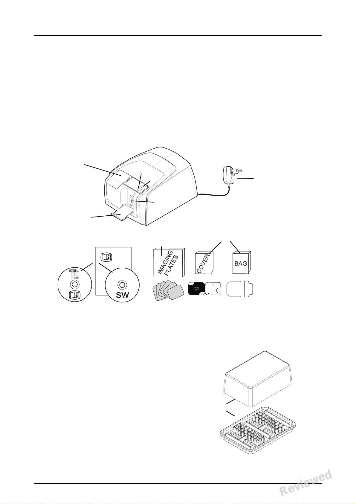
1Introduction
1. ON/OFF key
2. START key
3. Display
4. Imaging plate collector
5. Plate slot and plate carrier
6. Power supply
CAUTION:
Only use the power supply delivered with the unit or an approved
spare power supply supplied by
an authorized distributor (See
chapter Technical Specifications).
7. Documentation and
imaging application software
media
8. Hygiene accessories
9. Imaging plates
10. Imaging plate storage box
10
8
9
7
6
3
2
1
5
4
KaVo Scan eXam™ One system is intended to be
used by dentist and other qualified dental
professionals to process x-ray images exposed to
the imaging plates from the intraoral complex of
the skull.
1.1 Unit with accessories
1 Introduction
See PDM system to determine the status of this document. Printed out: 2017-03-17 10:35:17
Copyright © by PaloDEx Group Oy. All rights reserved.
KaVo Scan eXam One 1
Reviewed: Jalkanen Joni 2017-02-13 16:00
Approved:
D510414, 5
Reviewed
Page 10
1 Introduction
1
2
3
4
5
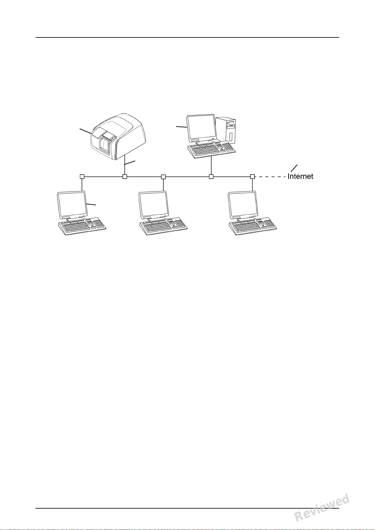
1.2 System setup
An example of a typical system set up in a local
area network (LAN).
1. Scan eXam™ One unit
2. Ethernet cable
3. Workstation (WS) computer (not included) contains
- patient data, images and a license server
4. Internet connection (optional, recommended)
5. Optional workstation (WS) computers (not included)
For more options and details of installing and
setting up the Scan eXam™ One system see
chapters 6 Installation of the imaging plate system
and 9 Technical specifications.
2 KaVo Scan eXam One
Reviewed: Jalkanen Joni 2017-02-13 16:00
Approved:
See PDM system to determine the status of this document. Printed out: 2017-03-17 10:35:17
Copyright © by PaloDEx Group Oy. All rights reserved.
D510414, 5
Reviewed
Page 11
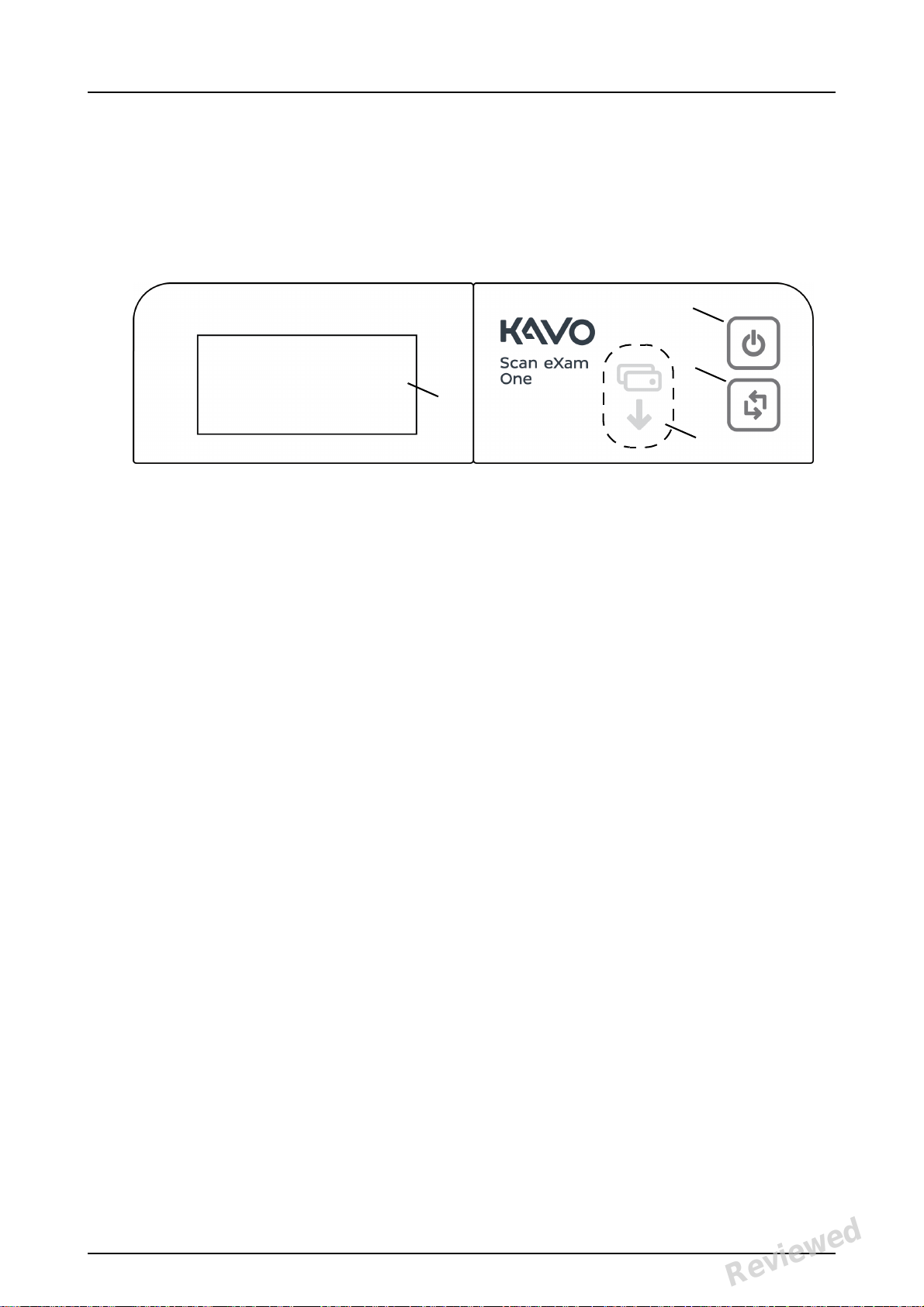
1.3 Controls and indicators
4
1
2
3
Control panel layout
1. ON/OFF key
2. START key
3. Plate feeding indicator
4. Status display
1 Introduction
ON/OFF key
• Press ON/OFF key to turn the unit on.
• Press and hold for 3 seconds to turn the unit
off.
• They key has a light when the unit is on.
• The light is softly blinking when the unit is in
a stand by mode.
• Press the ON/OFF key or the START key to
wake the unit.
START key
• Use the start key to wake the unit from the
stand by mode or
• to start processing in the manual mode or to
cancel (skip) the 2nd plate in the Occlusal 4C
mode.
• to access startup screen-information (IP, se-
rial number) when the scanner is not reserved by any user.
KaVo Scan eXam One 3
Reviewed: Jalkanen Joni 2017-02-13 16:00
Approved:
See PDM system to determine the status of this document. Printed out: 2017-03-17 10:35:17
Copyright © by PaloDEx Group Oy. All rights reserved.
D510414, 5
Reviewed
Page 12
1 Introduction
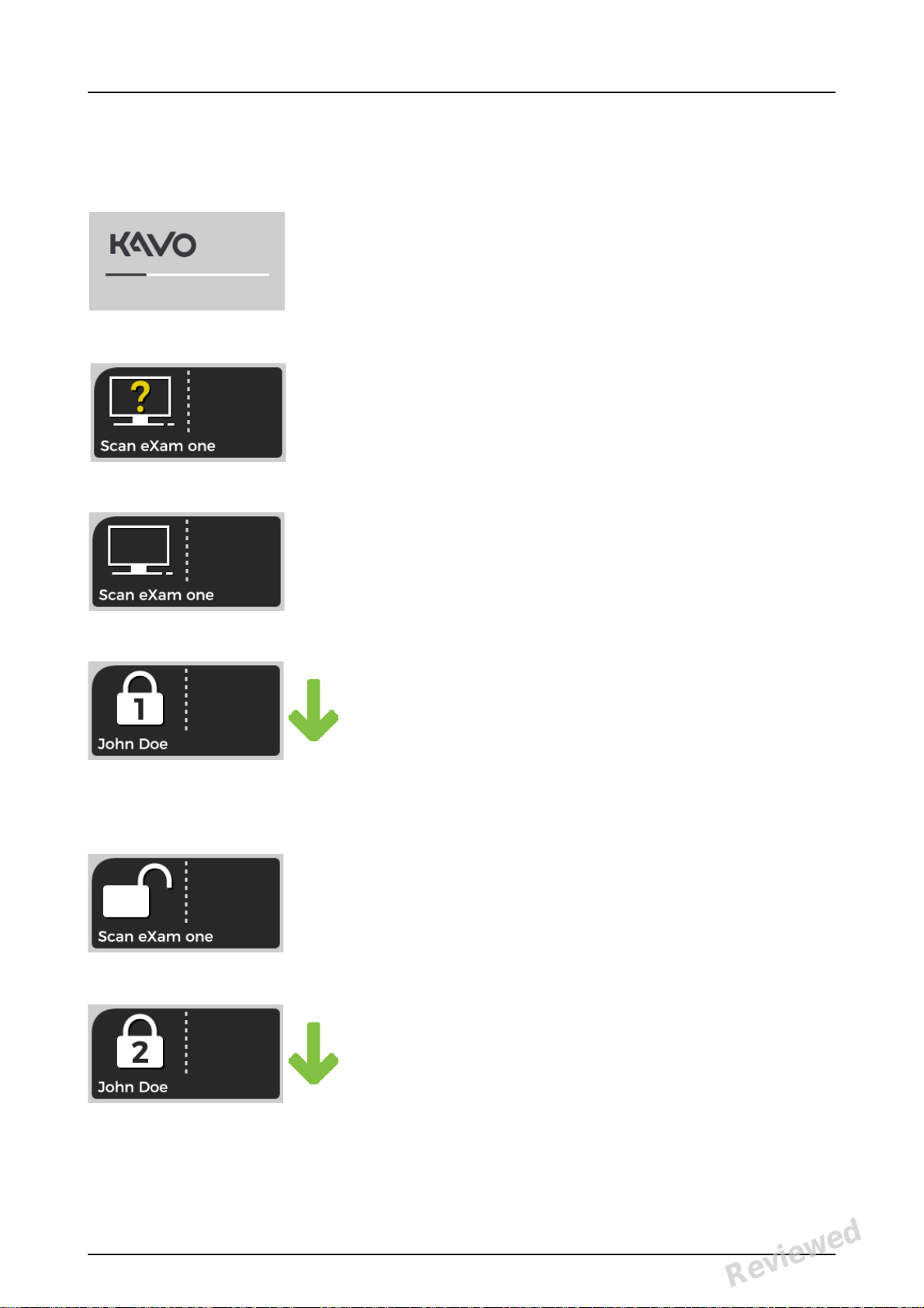
Display and plate feeding indicators
Startup
During startup the unit serial number, IP address
and other information will appear on the unit display.
Waiting dental imaging software
Software not open, not ready or waiting for user
action.
Unit name is displayed.
Software active
Unit has a connection to a software. Unit not in
use.
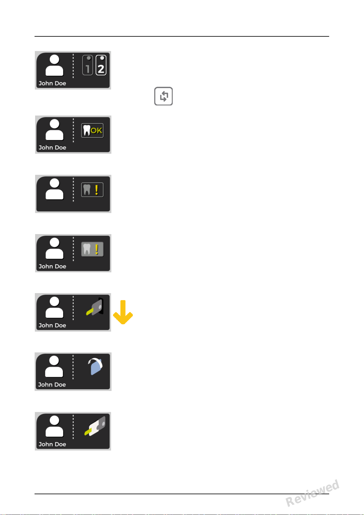
Express Share reservation
The unit has been reserved using Express Share.
The workstation identifier is shown in the padlock. The name of the current patient is shown.
The green plate feeding indicator is showing
readiness for plate insert.
Express Share ready
Unit has a connection to a software using Express Share.
The unit is not reserved by any workstation in the
system.
Unit is activated
The unit is activated for image processing. The
name of the current patient is shown.
The green plate feeding indicator is showing
readiness for plate insert.
4 KaVo Scan eXam One
Reviewed: Jalkanen Joni 2017-02-13 16:00
Approved:
See PDM system to determine the status of this document. Printed out: 2017-03-17 10:35:17
Copyright © by PaloDEx Group Oy. All rights reserved.
D510414, 5
Reviewed
Page 13
1 Introduction
Insert 2nd plate
Insert the second plate of the Occlusal 4C format.
Press Start to treat the first plate as a
single size 3 image.
Image processing complete
Exposure level OK.
Image processing complete
Image considered over exposed. Check exposure
settings.
Image processing complete
Image considered under exposed. Check exposure settings.
Remove plate
Remove the imaging plate from the plate carrier.
Rotate the plate
Rotate the imaging plate. Light blue side to the
left.
Remove cover
Remove the hygienic cover gently leaving the
imaging plate in the plate carrier.
KaVo Scan eXam One 5
Reviewed: Jalkanen Joni 2017-02-13 16:00
Approved:
See PDM system to determine the status of this document. Printed out: 2017-03-17 10:35:17
Copyright © by PaloDEx Group Oy. All rights reserved.
D510414, 5
Reviewed
Page 14
1 Introduction
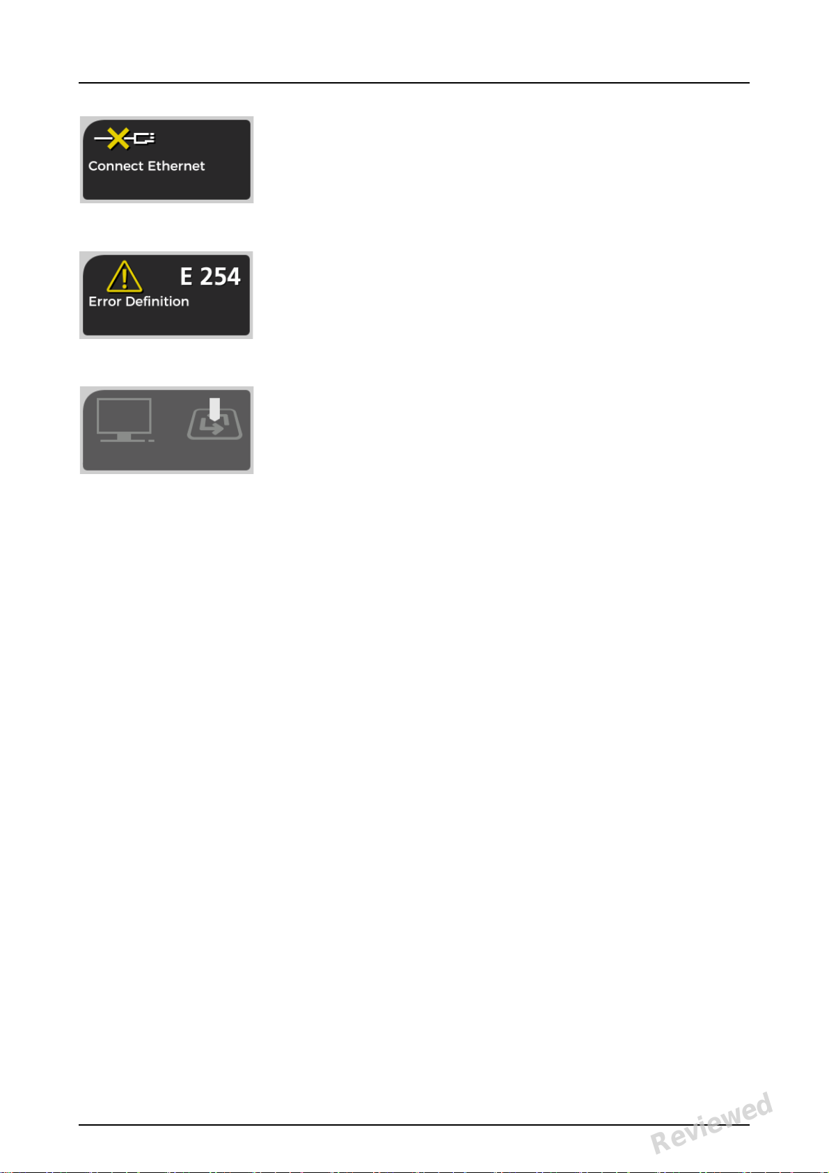
Unit disconnected
Missing ethernet connection. Check the connectors, cables and the network.
Error
Error ID and a short description is displayed.
Contact service.
Press START
Press the START button to wake the unit from a
standby mode.
6 KaVo Scan eXam One
Reviewed: Jalkanen Joni 2017-02-13 16:00
Approved:
See PDM system to determine the status of this document. Printed out: 2017-03-17 10:35:17
Copyright © by PaloDEx Group Oy. All rights reserved.
D510414, 5
Reviewed
Page 15
2 Basic use
1
2
5
4
3
6
1
2
3
4
2 Basic use
Prepare imaging plates.
See chapter 2.1 for more information.
Activate the Scan eXam™ One from the imaging application.
Refer to the application software manual for
more information.
Position and take an exposure.
See chapter 2.2 for more information.
Process the imaging plate.
See chapter 2.4 for more information.
KaVo Scan eXam One 7
Reviewed: Jalkanen Joni 2017-02-13 16:00
Approved:
See PDM system to determine the status of this document. Printed out: 2017-03-17 10:35:17
Copyright © by PaloDEx Group Oy. All rights reserved.
D510414, 5
Reviewed
Page 16
2 Basic use
CAUTION! Process unexposed imaging plates to
erase potentially accumulated background radiation
when
• Taking new imaging plates into use.
• Imaging plates have been packaged and un-
used for more than 24 hours.
• Imaging plates have stored in dark (not ex-
posed to ambient light) susceptible for background radiation for more than 24 hours.
This will remove any potential fogging due to
collected natural background radiation.
8 KaVo Scan eXam One
Reviewed: Jalkanen Joni 2017-02-13 16:00
Approved:
See PDM system to determine the status of this document. Printed out: 2017-03-17 10:35:17
Copyright © by PaloDEx Group Oy. All rights reserved.
D510414, 5
Reviewed
Page 17

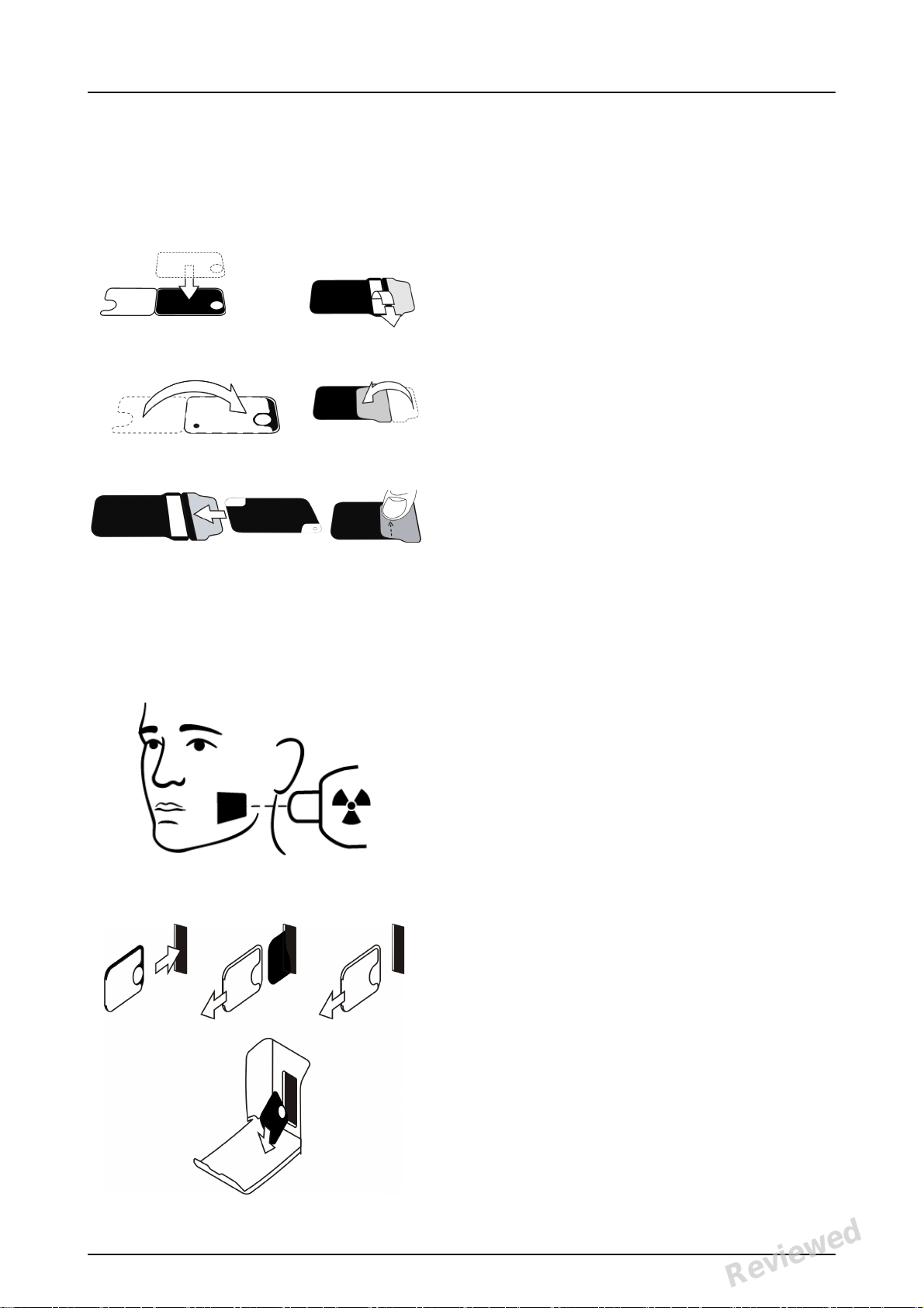
2.1 Preparing the imaging plates
Apply protective cover and package the plates into
the original hygiene bag.
Seal the bag properly.
Observe the orientation of the plates, cover and the
bag.
Active side of the imaging plate has a light blue
color.
2 Basic use
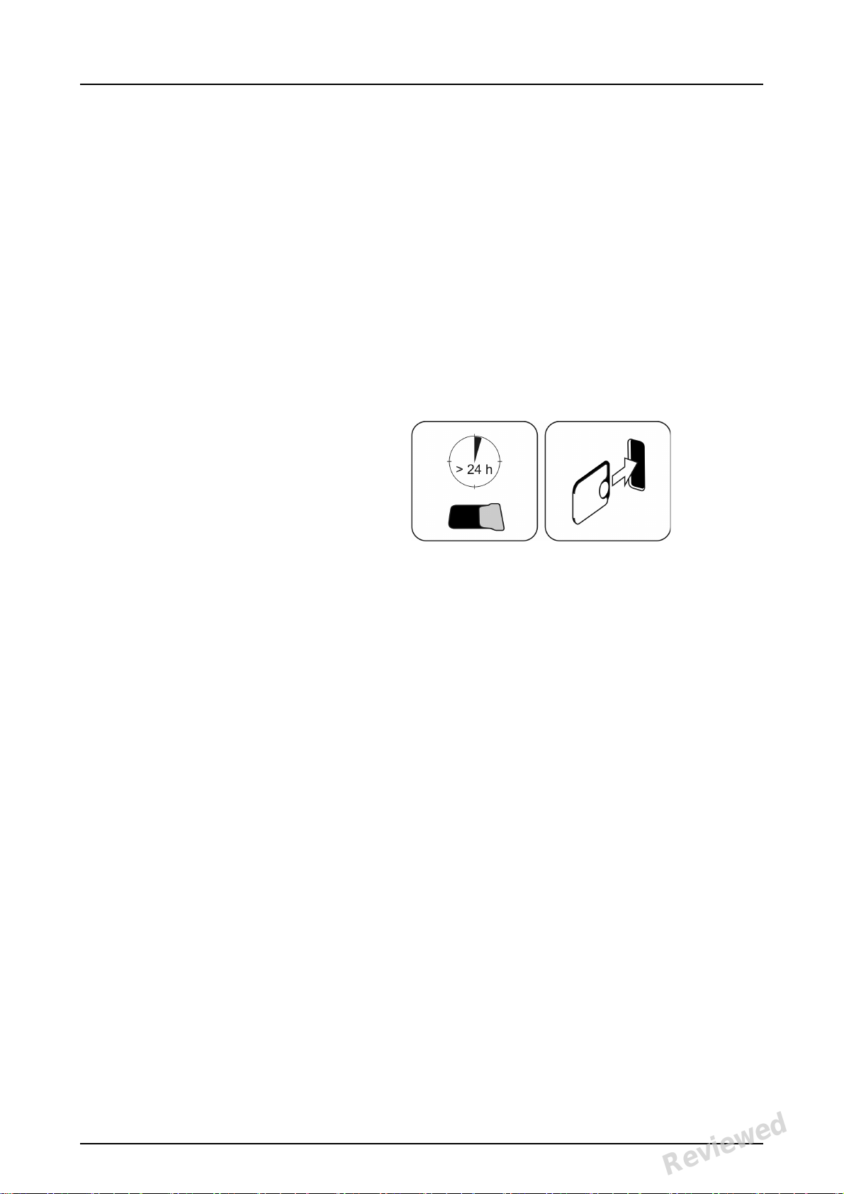
NOTICE! Keep the imaging plates packed max. 24
hours before using. Packaged plates accumulate
radiation from the background. Plates can be
erased by reading the plate.
KaVo Scan eXam One 9
Reviewed: Jalkanen Joni 2017-02-13 16:00
Approved:
See PDM system to determine the status of this document. Printed out: 2017-03-17 10:35:17
Copyright © by PaloDEx Group Oy. All rights reserved.
D510414, 5
Reviewed
Page 18

2 Basic use
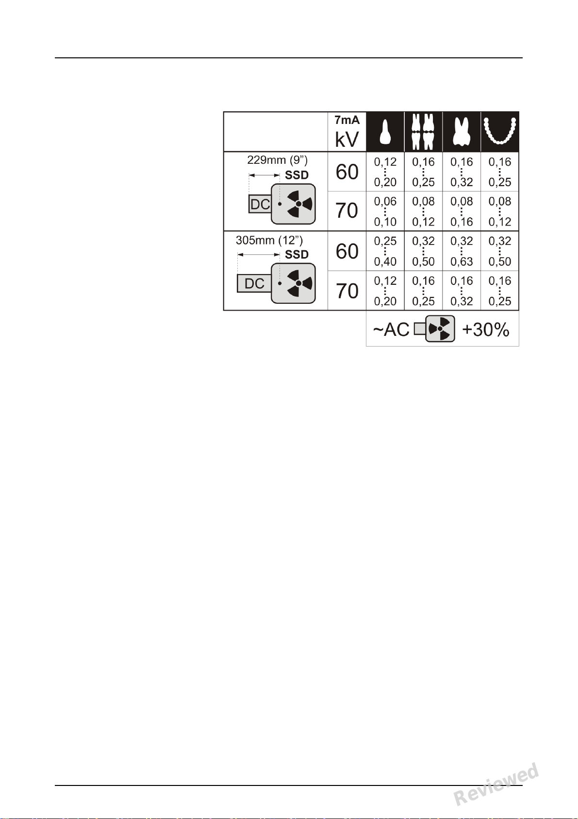
2.2 Positioning and exposure
Position the imaging plate according to the
anatomical area of interest. Holders (petitioners)
are recommended for the best positioning
accuracy. See the chapter 4.4 Holders, for more
information.
Apply X-ray according to the anatomical area of
interest and on the intraoral X-ray tube in use.
Find guidelines of exposure times in seconds for a
standard DC X-ray unit in the table below.
Correct exposure settings depend on the X-ray unit
type in use. For an AC-unit or for a low tube current
(i.e. portable X-ray) apply higher exposure times.
10 KaVo Scan eXam One
Reviewed: Jalkanen Joni 2017-02-13 16:00
Approved:
See PDM system to determine the status of this document. Printed out: 2017-03-17 10:35:17
Copyright © by PaloDEx Group Oy. All rights reserved.
D510414, 5
Reviewed
Page 19
2 Basic use
Exposure factors close to F-speed film are often
appropriate.
KaVo Scan eXam One 11
Reviewed: Jalkanen Joni 2017-02-13 16:00
Approved:
See PDM system to determine the status of this document. Printed out: 2017-03-17 10:35:17
Copyright © by PaloDEx Group Oy. All rights reserved.
D510414, 5
Reviewed
Page 20
2 Basic use
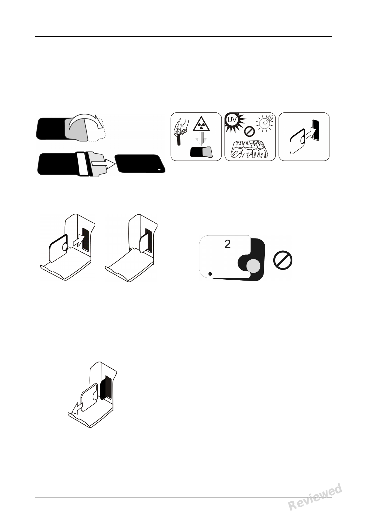
2.3 Processing the imaging plates
Unpack and process the imaging plates
immediately after unpacking.
NOTICE! Ambient light harms the image information when not protected by the protective cover.
Insert the imaging plate with the cover.
NOTICE! Do not partially slide the imaging
plate from the cover. You can place the
plate with cover and leave it to the plate carrier. Unit will not start the processing before
removing the cover.
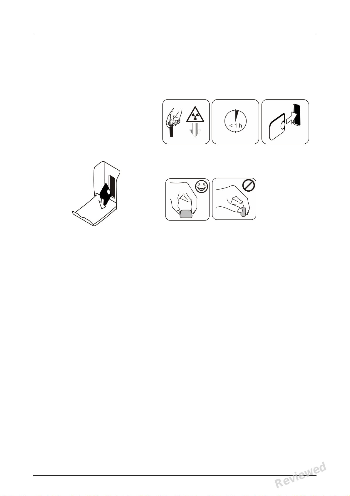
Remove the cover.
12 KaVo Scan eXam One
Reviewed: Jalkanen Joni 2017-02-13 16:00
Approved:
See PDM system to determine the status of this document. Printed out: 2017-03-17 10:35:17
Copyright © by PaloDEx Group Oy. All rights reserved.
D510414, 5
Reviewed
Page 21
2 Basic use
The image appears on the imaging application screen.
NOTICE! Process within one hour after exposure.
Processed imaging plate is ready to be
packed and exposed again.
KaVo Scan eXam One 13
Reviewed: Jalkanen Joni 2017-02-13 16:00
Approved:
See PDM system to determine the status of this document. Printed out: 2017-03-17 10:35:17
Copyright © by PaloDEx Group Oy. All rights reserved.
D510414, 5
Reviewed
Page 22

2 Basic use
14 KaVo Scan eXam One
Reviewed: Jalkanen Joni 2017-02-13 16:00
Approved:
See PDM system to determine the status of this document. Printed out: 2017-03-17 10:35:17
Copyright © by PaloDEx Group Oy. All rights reserved.
D510414, 5
Reviewed
Page 23

3Advanced use
3.1 Scan eXam™ One setup options
The Scan eXam™ One setup options allow you to
configure the Scan eXam™ One to the user’s
clinical preferences.
From the imaging application software you are
using select unit Setup/Scanner page (for more
instruction on how to access setup page review
application software manual).
3 Advanced use
3.1.1 Status
Shows the scanner type, firmware version and unit
serial number.
KaVo Scan eXam One 15
Reviewed: Jalkanen Joni 2017-02-13 16:00
Approved:
See PDM system to determine the status of this document. Printed out: 2017-03-17 10:35:17
Copyright © by PaloDEx Group Oy. All rights reserved.
D510414, 5
Reviewed
Page 24

3 Advanced use
3.1.2 Image Scanning
If Show Image Preview and Dental Chart is selected
a preview image with a dental chart for tooth
numbering appears before the image is saved.
3.1.3 Using the dental chart
1. After an imaging plate has been processed a
window
2. opens that shows a preview image and a dental
chart.
Click the tooth / teeth on the chart that correspond to the tooth / teeth in the image. Tooth
numbers are assigned to the selected teeth.
The tools at the top of the window allow the image
to be manipulated.
3. Click OK to save the image and tooth numbers.
3.1.4 Resolution
Super gives a pixel size of 30 μm. This results in
images with better resolution, but may require
longer exposure time to compensate.High
(recommended default) gives a pixel size of 60 μm.
This results in images with less noise especially if
short exposure times are used.
3.1.5 Image Processing - Noise
Filtering
Noise filtering makes images smoother when they
are taken at short exposure times. There are two
options available: Classic mode offers traditional
noise filtering algorithms that has been applied to
all previous models of imaging plate systems.
The Progressive mode applies another algorithm
that reduces noise while efficiently retaining image
clarity. The progressive algorithm requires
appropriate exposure level for efficient
16 KaVo Scan eXam One
Reviewed: Jalkanen Joni 2017-02-13 16:00
Approved:
See PDM system to determine the status of this document. Printed out: 2017-03-17 10:35:17
Copyright © by PaloDEx Group Oy. All rights reserved.
D510414, 5
Reviewed
Page 25

3 Advanced use
performance. Ensure that the exposure level
indicator is Ok.
3.1.6 Retrieve last image
If the last image processed is not transferred to the
PC because of a network, communication, PC or
software failure, the last image processed can be
retrieved.
NOTICE! The LAST processed image can only be
retrieved if the unit is left on. If the unit is switched
off the image is lost.
1. To retrieve the last processed image:
1. Correct the problem that caused the communication failure. When the connection between the
unit and the PC is re-established the last processed image is automatically transferred to the
PC.
2. PC: If the image is not automatically transferred
to the PC, select the Setup > Scanner page from
the imaging application software your are using.
3. PC: In the Last Image field, click Retrieve now
to retrieve the last processed image.
NOTICE! If required you can select different parameters (e.g. resolution, show image preview
etc.) for the image to be retrieved.
4. PC: Click OK to close the Setup window. The last
processed image is transferred to the PC.
3.1.7 Scanner Unit Serial number
Adds the unit serial number to all new images.
KaVo Scan eXam One 17
Reviewed: Jalkanen Joni 2017-02-13 16:00
Approved:
See PDM system to determine the status of this document. Printed out: 2017-03-17 10:35:17
Copyright © by PaloDEx Group Oy. All rights reserved.
D510414, 5
Reviewed
Page 26

3 Advanced use
3.2 Settings
See chapter Installation for more information on
connecting the unit to a PC/LAN.
3.3 Workflow
From the imaging application software you are
using select unit Setup / Workflow page.
3.3.1 Readout start
Select Automatic if you want the unit to start
automatically image plate processing.The Start
after options all ow to select when the unit starts
image plate processing:
• After Plate insert: processing starts auto-
matically when it detects right way inserted
imaging plate in the plate carrier.
• After Cover removal: after the imaging plate
and protective cover have been inserted into
18 KaVo Scan eXam One
Reviewed: Jalkanen Joni 2017-02-13 16:00
Approved:
See PDM system to determine the status of this document. Printed out: 2017-03-17 10:35:17
Copyright © by PaloDEx Group Oy. All rights reserved.
D510414, 5
Reviewed
Page 27

3 Advanced use
the plate carrier, processing starts automatically when the protective cover is removed.
The Start delay options allow the start delay time
to be selected.
• Short = approximately 0.2 seconds
• Medium = approximately 0.4 seconds (rec-
ommended default)
• Long = approximately 0.6 seconds
Select Manual if you want processing to start only
when the START key is pressed.
NOTICE! Processing starts even if the plate is:
• Wrong way round
•Not detected
• Not inserted at all
NOTICE! Unit turns off in manual mode if user is
pressing ON/ OFF key regardless of imaging plate
sensing in the plate carrier.
KaVo Scan eXam One 19
Reviewed: Jalkanen Joni 2017-02-13 16:00
Approved:
See PDM system to determine the status of this document. Printed out: 2017-03-17 10:35:17
Copyright © by PaloDEx Group Oy. All rights reserved.
D510414, 5
Reviewed
Page 28

3 Advanced use
3.3.2 Plate eject mode
•The options are:Drop in plate collector:
the imaging plate is ejected into the plate
collector after the imaging plate has been
processed.
• Leave in plate carrier: the imaging plate
remains in the plate carrier after the imaging
plate has been processed.
The Leave in plate carrier option is recommended for users who want to handle the
imaging plates with more care and reduce
wear and tear on them. This option extends
service life of the imaging plates and allows
greater hygiene standards to be observed.
3.4 Power options
From the imaging application software you are
using select unit Setup / Power options page.
Standby after (seconds): Allows you to select
the period of time the unit remains unused before it
enters the standby mode (plate carrier is driven
20 KaVo Scan eXam One
Reviewed: Jalkanen Joni 2017-02-13 16:00
Approved:
See PDM system to determine the status of this document. Printed out: 2017-03-17 10:35:17
Copyright © by PaloDEx Group Oy. All rights reserved.
D510414, 5
Reviewed
Page 29

3 Advanced use
inside the unit, door is closed and ON/OFF key dims
on and off). Press ON/OFF key to recover.
Beep when entering standby mode: Audible
signal is heard before the unit enters the standby
mode.
Shutdown after (minutes): Allows you to select
the period of time the unit remains in standby
mode before automatically switching itself off.
3.5 Occlusal 4C projection imaging (not included in delivery)
To change Occlusal 4C projection imaging settings
select from the imaging application software unit
Setup / Occlusal page.
Occlusal 4C projection image is formed from two
sequential size 3 plates. Image plates are
processed separately and then stitched together to
form a single Occlusal 4C projection image.
Following text shortly describe how Occlusal 4C
projection image is taken. For more information
refer to instructions supplied with the Occlusal 4C
kit.
1. Place two size 3 imaging plates into their corre-
sponding protective covers.
2. Slide the two size 3 imaging plates and protec-
KaVo Scan eXam One 21
Reviewed: Jalkanen Joni 2017-02-13 16:00
Approved:
See PDM system to determine the status of this document. Printed out: 2017-03-17 10:35:17
Copyright © by PaloDEx Group Oy. All rights reserved.
D510414, 5
Reviewed
Page 30

3 Advanced use
tive covers into the Occlusal 4C bite protector.
3. Insert the Occlusal 4C bite protector and imag-
ing plates into the Occlusal 4C hygiene bag.
4. Seal the bag. Place the sealed Occlusal 4C hy-
giene bag into the patient’s mouth and take an
exposure.
5. Remove the sealed Occlusal 4C hygiene bag
from the patient’s mouth. Open it.
6. Remove each individual imaging plate from the
Occlusal 4C bite protector and process one at a
time.
7. Occlusal 4C image appear on the imaging
application software.
NOTICE! When you are in the Occlusal 4C mode it
is possible to temporarily override the mode and
process a single size 3 imaging plate. Insert the
size 3 imaging plate into the unit so that it can be
processed. When the insert second plate symbol
appears on the unit user interface press the start
key. This cancels the Occlusal 4C mode for this
operation and produce a single size 3 image.
Size 3 image mode from each size 3 plate allows
size 3 imaging plates to process as individual
imaging plates.
NOTICE! Due to Occlusal 4C projection imaging
geometry and imaging plate positioning, accurate
distance and angle measurements cannot be taken
from Occlusal 4C projection images.
22 KaVo Scan eXam One
Reviewed: Jalkanen Joni 2017-02-13 16:00
Approved:
See PDM system to determine the status of this document. Printed out: 2017-03-17 10:35:17
Copyright © by PaloDEx Group Oy. All rights reserved.
D510414, 5
Reviewed
Page 31

4 Accessories introduction
Protective covers
Hygiene bags
4 Accessories introduction
NOTICE! USE ONLY GENUINE ACCESSORIES FROM
THE MANUFACTURER to ensure the optimal clinical
results, safe use of the system and long service life
for the imaging plates.
NOTICE! Never use hygiene accessories more than
once.
4.1 Hygiene accessories
KaVo Scan eXam One 23
Reviewed: Jalkanen Joni 2017-02-13 16:00
Approved:
See PDM system to determine the status of this document. Printed out: 2017-03-17 10:35:17
Copyright © by PaloDEx Group Oy. All rights reserved.
D510414, 5
Reviewed
Page 32

4 Accessories introduction
4.2 Imaging plates
Compatible with all intraoral sizes equal to film: 0,
1, 2, 3 and Occlusal 4C, all with film-like usability.
IDOT™ imaging plates have individual
identification marking that appear on the images.
Standard (STD) imaging plates (optional)
have no identification mark on the sensitive side of
the plate.
24 KaVo Scan eXam One
Reviewed: Jalkanen Joni 2017-02-13 16:00
Approved:
See PDM system to determine the status of this document. Printed out: 2017-03-17 10:35:17
Copyright © by PaloDEx Group Oy. All rights reserved.
D510414, 5
Reviewed
Page 33

4 Accessories introduction
4.3 Imaging plate storage box
Practical, dedicated storage box keeps imaging
plates clean and ready for use by protecting the
plates from:
• Dust (which will be visible in the image)
• Airborne contamination
• Fogging caused by background radiation
(which may decrease image quality)
• Ultraviolet radiation (which is harmful for the
imaging plates)
Base part of the storage box is autoclavable at 121
°C
(250 F) or 134 °C (272 F). The top cover cannot be
autoclaved.
4.4 Holders
It is recommended to use imaging plate holders to
ensure accurate patient positioning and
consistently good image quality. Problems caused
by manually positioning the imaging plate include:
• incorrect vertical alignment
• distortion
• cone cut off
• poor projection standardization
• inferior image quality
• contamination risk
Contact your distributor for more information on
imaging with plate holders.
KaVo Scan eXam One 25
Reviewed: Jalkanen Joni 2017-02-13 16:00
Approved:
See PDM system to determine the status of this document. Printed out: 2017-03-17 10:35:17
Copyright © by PaloDEx Group Oy. All rights reserved.
D510414, 5
Reviewed
Page 34

4 Accessories introduction
4.5 Occlusal projection imaging with Occlusal 4C start-up kit and accessories
The complete image is produced automatically from
two size 3 imaging plates. The plates are shielded
from biting damage with a rigid bite protector. For
more information see instructions provided with the
Occlusal 4C kit and on chapter Advanced use.
4.6 Microfiber cloth
Imaging plate microfiber cloth is used for dry
cleaning of the imaging plates (comparable to
eyeglasses cleaning).
4.7 Imaging plate care
Sensitive surface,
handle with care
You can bend. Do not fold or
Touch the edges
only.
Do not scratch. Do not stab.
Use only original
accessories.
Single use only!
bend
excessively.
Do not touch the
sensitive surface.
26 KaVo Scan eXam One
Reviewed: Jalkanen Joni 2017-02-13 16:00
Approved:
See PDM system to determine the status of this document. Printed out: 2017-03-17 10:35:17
Copyright © by PaloDEx Group Oy. All rights reserved.
D510414, 5
Reviewed
Page 35

4 Accessories introduction
Avoid moist and
water.
Allowed
temperature.
Avoid direct
sunlight and
UV radiation.
4.8 Imaging plate cleaning
Do not sink.
Avoid dust.
Not household
waste.
Use ONLY > 70%
Ethanol
Do not apply
Ethanol directly
on the plate.
Apply Ethanol on
lint free soft fabric.
KaVo Scan eXam One 27
Reviewed: Jalkanen Joni 2017-02-13 16:00
Approved:
See PDM system to determine the status of this document. Printed out: 2017-03-17 10:35:17
Copyright © by PaloDEx Group Oy. All rights reserved.
D510414, 5
Reviewed
Page 36

4 Accessories introduction
Wipe the plate
gently.
Wipe dry or let dry
for 1 minute.
Pack the plate.
NOTICE! Pack the imaging plates in advance, but
no longer than 24 hours before the exposure.
28 KaVo Scan eXam One
Reviewed: Jalkanen Joni 2017-02-13 16:00
Approved:
See PDM system to determine the status of this document. Printed out: 2017-03-17 10:35:17
Copyright © by PaloDEx Group Oy. All rights reserved.
D510414, 5
Reviewed
Page 37

5 Introduction to imaging plate technique
Sensitive side
1. Protective (topcoat)
layer
2. Photo-stimulable layer
3. Support material layer
(=back side, black)
5 Introduction to imaging plate
technique
5.1 Imaging plate
Imaging plate is a film-like thin, flexible and
wireless phosphorescent plate, which works as a
wireless receptor. Imaging plate is better than film
because:
• no need for film development chemicals and
darkroom.
• tolerates wider range of exposure values,
both overexposure and underexposure are
practically eliminated.
• All benefits of digital images.
Imaging plate sizes:
•0 child
• 1 small adult
•2 large adult
•3 bitewing
• 4C occlusion
The support base material is black plastic. On top of
the base material is blueish photo-stimulable layer
(does not contain any prosphor/phosphorus). On
top of the blueish material is a top coat protective
layer and the edges are closed with lacquer.
The phosphorescent side of the plate records and
stores the image. This side is sensitive and should
be protected against dust and dirt.
Visible light clears the image information from the
plate, so it must be protected from ambient light
between exposure and processing.
Even when packed properly, the image starts to
fade out slightly within time.
See PDM system to determine the status of this document. Printed out: 2017-03-17 10:35:17
Copyright © by PaloDEx Group Oy. All rights reserved.
KaVo Scan eXam One 29
Reviewed: Jalkanen Joni 2017-02-13 16:00
Approved:
D510414, 5
Reviewed
Page 38

5 Introduction to imaging plate technique
5.2 Hygiene accessories
The imaging plate is protected with a protective cover and a hygiene bag before the exposure. Protective cover and hygiene bag are protecting the plate
from:
•Ambient light
• Contamination
•Mechanical wearing
•Moisture
NOTICE! USE ONLY GENUINE, ORIGINAL HYGIENE
ACCESSORIES AND IMAGING PLATES DESIGNED
FOR THIS SYSTEM AND SUPPLIED BY AUTHORIZED
DISTRIBUTOR. The manufacturer of this system
will not be held responsible for any problems
caused by using accessories from other
manufacturers. PROPER USE OF ORIGINAL
HYGIENE ACCESSORIES ENSURES THE BEST
IMAGE QUALITY AND MAXIMUM SERVICE LIFE OF
THE IMAGING PLATES.
The packed imaging plate is positioned with a
holder in the patient’s mouth. The exposure is
made as with film. The hygiene bag should be
disinfected after exposure and disposed off after
single use.
1. Imaging plate is inserted together with the protective cover all the way into the plate slot.
2. Magnet on the plate carrier grabs the imaging
plate.
3. Processing starts automatically after you remove the protective cover.
Dispose protective cover after single use.
30 KaVo Scan eXam One
Reviewed: Jalkanen Joni 2017-02-13 16:00
Approved:
See PDM system to determine the status of this document. Printed out: 2017-03-17 10:35:17
Copyright © by PaloDEx Group Oy. All rights reserved.
D510414, 5
Reviewed
Page 39

5 Introduction to imaging plate technique
1.
2.
3.
KaVo Scan eXam One 31
Reviewed: Jalkanen Joni 2017-02-13 16:00
Approved:
See PDM system to determine the status of this document. Printed out: 2017-03-17 10:35:17
Copyright © by PaloDEx Group Oy. All rights reserved.
D510414, 5
Reviewed
Page 40

5 Introduction to imaging plate technique
1.
2.
4.
5.3 Processing
1. Red laser light stimulates the sensitive surface
of the imaging plate.
2. Imaging plate glows blue light in relation to the
amount of X-ray information stored to the plate.
3. Glowing blue light is optically collected pixel by
pixel (line by line) and measured with extremely
sensitive photodetector.
4. Digital image is formed from the measured light
intensity variation.
After stimulating, imaging plate is exposed to
bright light, which clears the remaining image
information from the plate. The imaging plate is
dropped out of the unit.
X-ray exposures and processing are not aging the
imaging plate, so it is re-usable hundreds of times.
In practice, mechanical wearing limits the service
life of the plate.
32 KaVo Scan eXam One
Reviewed: Jalkanen Joni 2017-02-13 16:00
Approved:
See PDM system to determine the status of this document. Printed out: 2017-03-17 10:35:17
Copyright © by PaloDEx Group Oy. All rights reserved.
D510414, 5
Reviewed
Page 41

5 Introduction to imaging plate technique
5.4 Background radiation
The user can pack imaging plates ready for use.
However, it is not recommended to store prepacked plates more than 24 hours.
NOTICE! Imaging plates react sensitively to
natural background radiation, which may cause
“fogging” and lack of contrast on the image.
The X-ray dose of single intraoral imaging is
approximately the same as the dose one person
gets from natural background radiation during one
day.
Imaging plates may gather radiation also during
transportation from the manufacturer. Therefore it
is recommended to perform initial erasing for the
new plates. This means that all imaging plates
should be processed once prior to use.
KaVo Scan eXam One 33
Reviewed: Jalkanen Joni 2017-02-13 16:00
Approved:
See PDM system to determine the status of this document. Printed out: 2017-03-17 10:35:17
Copyright © by PaloDEx Group Oy. All rights reserved.
D510414, 5
Reviewed
Page 42

5 Introduction to imaging plate technique
5.5 Light
Ambient light is good when storing the imaging
plates:
it keeps the plates clean from background radiation
“fogging”.
NOTICE! Ambient light is harmful for the image
information on the plate between the exposure and
processing.
NOTICE! UV light is harmful for the imaging plates.
34 KaVo Scan eXam One
Reviewed: Jalkanen Joni 2017-02-13 16:00
Approved:
See PDM system to determine the status of this document. Printed out: 2017-03-17 10:35:17
Copyright © by PaloDEx Group Oy. All rights reserved.
D510414, 5
Reviewed
Page 43

6 Installation of the imaging plate system
6 Installation of the imaging plate
system
Imaging plate system is formed of one or more PC
that connects the imaging plate scanner unit,
software, accessories and consumables.
Electronic equipment that does not fulfill medical
safety standards (office PC, network connecting
units etc.) must not be installed in the patient area.
The definition of the patient area is 1,5 m in
horizontal distance and 2.5 m in vertical distance to
the patient. The Scan eXam™ One meets safety
requirements of a medical electrical unit and it can
be installed also in the patient area.
6.1 Positioning the unit
Position the unit on a stable flat surface so that any
potential vibrations do not degrade the image
quality. The unit must not be positioned so that it is
touching other equipment. It must not be placed on
top of or under other equipment.
Do not position the unit in direct sunlight or near
bright light. Sunlight or bright light must not be
allowed to shine directly on the unit door into which
the imaging plates are inserted.
Typical location for a scanner unit in a shared use
by multiple operators is somewhere in a common
space for all users having an easy access to.
KaVo Scan eXam One 35
Reviewed: Jalkanen Joni 2017-02-13 16:00
Approved:
See PDM system to determine the status of this document. Printed out: 2017-03-17 10:35:17
Copyright © by PaloDEx Group Oy. All rights reserved.
D510414, 5
Reviewed
Page 44

6 Installation of the imaging plate system
If the X-ray images are being captured and images
scanned in a single location only (X-ray room or
single user environments) it is most convenient to
place the scanner unit near to the X-ray.
NOTICE! Always position the unit so that you can
easily detach the power supply (PSU) from supply
mains.
6.2 Connecting the unit to a network
The unit can be connected directly to a single PC or
several PC using a wired local area network (LAN).
It is recommended to use a LAN in all installations.
Also any workstation used for managing an image
capture should be connected to a wired LAN.
It is recommended to have an internet connection
from the LAN. This makes registering potential
software license easier.
36 KaVo Scan eXam One
Reviewed: Jalkanen Joni 2017-02-13 16:00
Approved:
See PDM system to determine the status of this document. Printed out: 2017-03-17 10:35:17
Copyright © by PaloDEx Group Oy. All rights reserved.
D510414, 5
Reviewed
Page 45

6 Installation of the imaging plate system
Connect the Ethernet cable from the unit to the
local area networking unit (router/switch). Consult
a computer network specialist to build up a local
area network if needed.
The unit can obtain an IP address automatically
(DHCP) or it can be set manually (static IP).
The unit will show its IP number during the boot up
sequence when powered on.
6.3 Install the Application software
The imaging plate system is delivered with an
software required to operate the system. In a
functional system there are two main parts: a
server for storing the patient data and images and
client software for operating the system and the
units. Both parts can be on the same computer but
there must be only one computer acting as
database server in a network. If the imaging plate
system is operated and images are viewed from
multiple PC in a network install only the client
software on the remaining other PC. The PC that is
acting as a server must be powered at any times
the system is used on any of the PC.
In addition there can be a license server in the local
area network to manage software licenses for
multiple PC.
KaVo Scan eXam One 37
Reviewed: Jalkanen Joni 2017-02-13 16:00
Approved:
See PDM system to determine the status of this document. Printed out: 2017-03-17 10:35:17
Copyright © by PaloDEx Group Oy. All rights reserved.
D510414, 5
Reviewed
Page 46

6 Installation of the imaging plate system
Turn the unit on by pressing the power ON/OFF
button before installing the software.
Insert the software installation media (DVD) and
launch the software installer if it does not start
automatically.
Read the software installation manual. Follow the
instructions of the installation wizard to complete
the software installation. Refer the software
installation manual for details.
6.4 Accessing the unit from the software
In order to operate the scanner unit from a PC the
software needs to access the desired scanner unit
in the network. There can be multiple scanners in
one network. When using multiple scanners each
unit can be assigned a unique call name by the user
to separate the scanners in the network. By default
the name of the scanner unit is “Scan eXam™
One”.
There are multiple ways of configuring the
connection between the scanner unit and the
operators software. The automatic connection is
based on automatically detecting the scanner in the
network. This is a preferred method.
6.4.1 Direct connection method (uses
the unit s/n)
NOTICE! It may not be possible to connect the unit
to the PC using the direct connection method if
another device is al ready connected to the PC
using direct connection. If the direct connection
field is not active (greyed out) or the system does
not work correctly after the unit has been
connected, reconnect the unit using the imaging
plate connection method.
1. After positioning the unit connect it to the PC(s)
in the local area network using the Ethernet cable (not included in delivery).
2. Switch the unit on. The imaging application soft-
ware symbol appears in the unit user interface.
This indicates that the unit is not communicating
with the PC(s)
in the network.
38 KaVo Scan eXam One
Reviewed: Jalkanen Joni 2017-02-13 16:00
Approved:
See PDM system to determine the status of this document. Printed out: 2017-03-17 10:35:17
Copyright © by PaloDEx Group Oy. All rights reserved.
D510414, 5
Reviewed
Page 47

6 Installation of the imaging plate system
3. PC: Install the imaging application software to
be used
in the PC(s).
4. PC: Open the imaging application software and
select the scanner setup window.
5. PC: From the scanner setup window select the
Settings tab to open the Scanner Connection
page.
6. PC: Select Direct Connection.
Key the serial number of the unit into the Scanner
serial number field. The serial number of the unit
appears on the type label on the back of the unit.
Make sure that the Computer network connection
that provides the LAN network connection is
selected.
6.4.2 IP method (using the unit static
address)
If your system does not allow the direct connection
method to be used to connect the PC(s), connection
can be done using an IP address.
1. Follow steps 1 to 5 from the previous section,
Direct connection method (uses the unit s/n).
2. PC: From the Settings tab select IP based and
then select the Enable changing IP address box.
Obtain an IP address for the unit from your network administrator and key it into the IP field in
the Scanner IP address area.
NOTICE! The PC and the unit must be in the
same subnet when setting the IP address of the
unit.
3. PC + Unit: Press and hold down the Start key
on the unit and then click Send to Scanner on
the settings window. You hear a beep which indicates that the PC is now sending the IP address the unit.
4. PC: Click OK to connect the PC to the unit.
5. Now connect the other PCs in the network to the
KaVo Scan eXam One 39
Reviewed: Jalkanen Joni 2017-02-13 16:00
Approved:
See PDM system to determine the status of this document. Printed out: 2017-03-17 10:35:17
Copyright © by PaloDEx Group Oy. All rights reserved.
D510414, 5
Reviewed
Page 48

6 Installation of the imaging plate system
unit. Just enter the IP address into the IP field
and then click OK to connect the PC to the unit
(it is not necessary to hold down the Start key
and click Send to Scanner with the other PCs
once the unit has already got an IP address).
6.4.3 EXPRESS Share
1. PC: If the unit is to be used with several PCs se-
lect the Use Multiconnect check box and select a
unique Workstation identifier number (between
1 and 4), for the PC being configured, from the
drop down list. Addition workstation information, for example, user name, location etc, can
be entered into the field next to the work
station identifier number.
NOTICE! If only one PC is connected to the unit
do not select the Use Multiconnect check box.
The Scanner Autorelease timeout is the length
of time that the unit remains reserved and unused by a PC before the PC automatically released the unit so that it can be used by another
PC in the system (the scanner can be reserved
in advance from another PC). The default setting
is 40 seconds. This can be changed by keying in
a new value.
2. Click OK to connect the PC to the unit.
3.
NOTICE! An automatic technique automatically
locates the unit within the local area network
and connect the PC.
4. Repeat the above process for all the other PCs in
the network. Make sure that you give each PC a
different Workstation identifier.
5. Check the installation by starting image capture
using the imaging application software. If the
Use Multiconnect was selected the Workstation
identifier of the PC (1 - 4) being used appears on
the unit user interface.
40 KaVo Scan eXam One
Reviewed: Jalkanen Joni 2017-02-13 16:00
Approved:
See PDM system to determine the status of this document. Printed out: 2017-03-17 10:35:17
Copyright © by PaloDEx Group Oy. All rights reserved.
D510414, 5
Reviewed
Page 49

6 Installation of the imaging plate system
6.5 Other devices
DO NOT connect any other devices to the unit or
the PC connected to the unit that are:
• not part of the supplied system
• not supplied by the manufacturer of the unit
• not recommended by the manufacturer of
the unit.
The PC connected to the unit should not be used in
the patient environment. The minimum horizontal
distance between the patient and the PC is 1.5 m
(4.5 ft). The minimum vertical distance between
the patient and the PC is 2.5 m (6.5 ft).
KaVo Scan eXam One 41
Reviewed: Jalkanen Joni 2017-02-13 16:00
Approved:
See PDM system to determine the status of this document. Printed out: 2017-03-17 10:35:17
Copyright © by PaloDEx Group Oy. All rights reserved.
D510414, 5
Reviewed
Page 50

6 Installation of the imaging plate system
42 KaVo Scan eXam One
Reviewed: Jalkanen Joni 2017-02-13 16:00
Approved:
See PDM system to determine the status of this document. Printed out: 2017-03-17 10:35:17
Copyright © by PaloDEx Group Oy. All rights reserved.
D510414, 5
Reviewed
Page 51

7Troubleshooting
7.1 Error images
7.1.1 Improper use of the hygiene accessories and imaging plates
Decreased contrast, shadows or shading,
ghost images…
Shows a “ghost image” (having shape of the plate
or other object). Plate not properly shielded from
light between exposure and process. Part of the
image erased by ambient light.
• Protective cover misused or not used at all.
• Hygiene bag not sealed properly.
• Improper, non-genuine hygiene accessories use.
7 Troubleshooting
• Improper storing of the imaging plates or
excessively high X-ray dose used.
• Imaging plate has been exposed to ultraviolet (UV) radiation.
• Imaging plate has collected background
radiation because:
- Plate has been stored near X-ray unit
- Plate has been stored in the bag or in
dark too long
• Use dedicated imaging plate storage box
to avoid these.
• Alternatively, perform initial erasing for
the plate(s) if they have been stored in
dark and/or near X-ray unit.
KaVo Scan eXam One 41
Reviewed: Jalkanen Joni 2017-02-13 16:00
Approved:
See PDM system to determine the status of this document. Printed out: 2017-03-17 10:35:17
Copyright © by PaloDEx Group Oy. All rights reserved.
D510414, 5
Reviewed
Page 52

7 Troubleshooting
7.1.2 Application errors
Improper x-ray settings used
Too dark image. Some areas showing uniform
“black”. Decreased diagnostic value.
• Too long exposure time/too high X-ray
dose.
Too light, noisy image with decreased diagnostic
value. Showing only part of the image.
Showing wrong size of the image (Image smaller
than imaging plate).
• Too short exposure time / Too low X-ray
dose.
42 KaVo Scan eXam One
Reviewed: Jalkanen Joni 2017-02-13 16:00
Approved:
See PDM system to determine the status of this document. Printed out: 2017-03-17 10:35:17
Copyright © by PaloDEx Group Oy. All rights reserved.
D510414, 5
Reviewed
Page 53

7 Troubleshooting
Ghost images, shadows
• Imaging plate has been exposed twice
without processing in
between.
• More than one image exposed to the same
plate.
• Imaging plate has not been erased properly after processing.
• Unit erasing leds are monitored during
normal operation. If leds are defected, application SW shows warning.
Circular shape on the image
Imaging plate has been exposed from the wrong
side, which shows the phantom of the metal disc
on the rear side of the plate.
KaVo Scan eXam One 43
Reviewed: Jalkanen Joni 2017-02-13 16:00
Approved:
See PDM system to determine the status of this document. Printed out: 2017-03-17 10:35:17
Copyright © by PaloDEx Group Oy. All rights reserved.
D510414, 5
Reviewed
Page 54

7 Troubleshooting
Cone cut
X-ray beam has exposed only part of the imaging
plate surface. Image may show on different
(smaller) size than the imaging plate used.
• Check exposure procedure.
• Use of proper holder avoids this.
Unsharp or blurred images, motion artefact
Patient or X-ray cone has moved during the exposure.
• Check exposure procedure.
• Check the stability of your intraoral X-ray
unit.
• Use proper holders.
• Too long exposure time may have been
used.
Use shorter exposure time (increase kV if
necessary to compensate effect of shorter
exposure time).
Geometry distortion
Improper patient positioning.
• Use proper holders to avoid this.
NOTICE! Never do accurate measurements on intraoral images unless having known size of reference object in the imaging plane.
44 KaVo Scan eXam One
Reviewed: Jalkanen Joni 2017-02-13 16:00
Approved:
See PDM system to determine the status of this document. Printed out: 2017-03-17 10:35:17
Copyright © by PaloDEx Group Oy. All rights reserved.
D510414, 5
Reviewed
Page 55

7 Troubleshooting
7.1.3 Imaging plate wearing
White or grey dots, spots or stains in images
• Dust or stains on the imaging plates.
•Any extra particle on top of the active sensitive surface of the plate is visible on the
image.
- Clean the plate(s).
- Replace if cleaning does not help.
- Pay attention on handling, storing and
mai nte nan ce. Ens ure that only the genuine
hygiene accessories are used.
Wearing of the imaging plate
Scratches
- Clean the plate(s).
- Replace if cleaning does not help.
- Pay attention on handling, storing and
mai nte nan ce. Ens ure that only the genuine
hygiene accessories are used.
Spots, dots (white or gray) or any visible pattern.
• Most probably caused by wearing of the
imaging plate.
• Can be caused by moisture or improper
cleaning.
- Clean the plate(s), ONLY >70% ETHANOL
MUST BE USED.
- Replace if cleaning does not help.
- Pay attention on handling, storing and
mai nte nan ce. Ens ure that only the genuine
hygiene accessories are used.
KaVo Scan eXam One 45
Reviewed: Jalkanen Joni 2017-02-13 16:00
Approved:
See PDM system to determine the status of this document. Printed out: 2017-03-17 10:35:17
Copyright © by PaloDEx Group Oy. All rights reserved.
D510414, 5
Reviewed
Page 56

7 Troubleshooting
7.2 Error messages
In unit user interface the wrench symbol and error
number indicates the error.
Number Description
1 K100 error
(CPU / main controller error)
2 PMT error (imaging plate infor-
mation cannot be read due to
photo detector not working)
3 Laser error (imaging plate infor-
mation cannot be read due to
laser not working)
4 Resonator error (imaging plate
information cannot be read due
mirror not moving properly)
12 K200 board not connected prop-
erly (laser detection, erasing &
movement control)
13 K300 board not connected prop-
erly (imaging plate sensing /
detection)
23 K200 error (erase LED, linear
movement detection sensor or
laser synchronization error)
24 Plate carrier movement error
34 Plate sensor error (imaging
plate cannot be detected)
123 Door movement error (position
of the door not detected or
movement is blocked)
124 Safety cover error (light cover
inside the unit is not in its place
/ not detected)
234 K400 control panel error (con-
1234 Other, see driver status window
Turn power off and on to see if the unit recovers. If
not, please contact local dealer or distributor.
46 KaVo Scan eXam One
Reviewed: Jalkanen Joni 2017-02-13 16:00
Approved:
See PDM system to determine the status of this document. Printed out: 2017-03-17 10:35:17
Copyright © by PaloDEx Group Oy. All rights reserved.
trol panel button defected /
stuck)
D510414, 5
Reviewed
Page 57

8 Other information
8.1 Quality control
To ensure maximum system performance
1. Observe “Exposure level” indication on the application SW to see that the x-ray settings are
optimal.
2. Perform self quality control regularly according
instructions provided with quality control test
set SP00267
(Intra digi QC IEC phantom w. instructions).
8.2 Unit care
WARNING:
Switch the unit off and disconnect it from the main
power supply before cleaning or disinfecting the
unit. Do not allow liquids to enter the unit.
8 Other information
8.3 Unit cleaning
To clean the unit use a non abrasive cloth
moistened with:
• cool or lukewarm water
•soapy water
• mild detergent
• isopropyl alcohol
• or ethanol (ethyl alcohol) 70 - 96%
• CaviCide, CaviWipes by Metrex
• FD322 by Dürr Dental
• Easydes by Kiilto
After cleaning wipe the unit with a non abrasive
cloth moistened with water. Never use solvents or
abrasive cleaners to clean the unit. Never use
unfamiliar or untested cleaning agents. If you are
not sure what the cleaning agent contains, DO NOT
use it.
If you use a spray cleaning agent DO NOT spray it
directly into the unit door.
KaVo Scan eXam One 47
Reviewed: Jalkanen Joni 2017-02-13 16:00
Approved:
See PDM system to determine the status of this document. Printed out: 2017-03-17 10:35:17
Copyright © by PaloDEx Group Oy. All rights reserved.
D510414, 5
Reviewed
Page 58

8 Other information
8.4 Disinfecting the unit
CAUTION:
Wear gloves and other protective clothing when
disinfecting the unit.
Wipe the unit with a cloth dampened with a suitable
disinfectant solution such as ethanol 96%. Never
use abrasive, corrosive or solvent disinfectants. All
surfaces must be dried before the unit is used.
WARNING:
Do not use any disinfecting sprays as the vapor
could ignite and cause injury.
Disinfecting techniques for both the unit and the
room where the unit is used must comply with all
local and national regulations and laws concerning
such equipment and its location.
8.5 Maintenance
The unit does not require any maintenance.
8.6 Repair
The unit does not require any maintenance. If the
unit is damaged or malfunctions in any way it must
only be repaired by service personnel authorized by
the manufacturer of the unit.
8.7 Disposal
At the end of the useful working life of the unit and/
or its accessories make sure that you follow
national and local regulations regarding the
disposal of the unit, its accessories, parts and
materials. The unit includes some or all of the
following parts that are made of or include
materials that are non-environmentally friendly or
hazardous:
• electronic circuit boards
• electronic components
• imaging plates
48 KaVo Scan eXam One
Reviewed: Jalkanen Joni 2017-02-13 16:00
Approved:
See PDM system to determine the status of this document. Printed out: 2017-03-17 10:35:17
Copyright © by PaloDEx Group Oy. All rights reserved.
D510414, 5
Reviewed
Page 59

9 Technical specifications
9 Technical specifications
9.1 Unit
Product name
Model
Product type
Intended use
Manufacturer
Quality system
KaVo Scan eXam™ One
eXam6
Intraoral digital imaging plate system
System is intended to be used only by dentist
and other qualified dental professionals to
process x-ray images exposed to the imaging
plates from the intraoral complex of the skull.
USA only
Federal law restricts this unit to sale by or on
the order of a dentist or other qualified professional.
PaloDEx Group Oy, Nahkelantie 160 (P.O.
Box 64)
FI-04300 Tuusula, FINLAND
In accordance with ISO13485 and ISO9001
standard
Environmental management
system
Conformity to standards
eXam6 Classification
IEC60601-1
In accordance with ISO14001
standard
IEC 60601-1: 1988 and A1+A2
IEC 60601-1-1: 2000
IEC 60601-1-4: 1996 and A1
IEC 60601-1-2: 2001
IEC 60601-1: 2005
EN 60825-1: 2007
UL 60601-1: 2003
CAN/CSA –C22.2 No. 601-1-M90 and S1+A2
/
DHHS 21 CFR Chapter I,
Subchapter J at the date of manufacture.
In conformity with the provisions of Council
Directive 93/ 42/EEC as amended by the Directive 2007/47/EC concerning medical devices.
- Class 2 equipment
- No applied part
- Continuous operation
- IPX0 (enclosed equipment without protection against ingress of liquids
KaVo Scan eXam One 49
Reviewed: Jalkanen Joni 2017-02-13 16:00
Approved:
See PDM system to determine the status of this document. Printed out: 2017-03-17 10:35:17
Copyright © by PaloDEx Group Oy. All rights reserved.
D510414, 5
Reviewed
Page 60

9 Technical specifications
Laser Safety Classification
Dimensions (H x W x D)
Weight
Power supply unit (PSU)
Operating voltage
Operating current
Power consumption
Pixel size (selectable)
Bit depth
Theoretical resolution
CLASS 1 LASER PRODUCT,
EN 60825-1 :2007
168 mm x 233 mm x 328 mm
(6.6 x 9.2 x 12.9 inches)
3,7 kg (8.2 lb)
CINCON TR30RAM240
FRIWO FW7362M/24
PHIHONG PSAM30R-240
24 VDC (External PSU:
100 – 240 VAC, 50/60 Hz)
Less than 1.25 A
Less than 30VA
30 μm (Super resolution) /
60 μm (High resolution)
16-bit
16,7 lp/mm
Firmware version
Interface connection
Plastic materials
Operating environment
Storage / transportation
environment
Other
1.0 or higher
Connection type RJ-45
Unshielded CAT 6 Ethernet cable
Used materials are phthalate free containing
< 0.1% w/w of DEHP and is not
manufactured from raw materials containing
or derived from Bisphenol A (BPA).
+10°C - +40°C, 30 – 90 RH%,
700 – 1060 mbar
-10°C – +50°C, 0 – 90 RH%,
500 – 1080 mbar
Integrated Kensington security slot for
securing unit with Microsaver series locks.
50 KaVo Scan eXam One
Reviewed: Jalkanen Joni 2017-02-13 16:00
Approved:
See PDM system to determine the status of this document. Printed out: 2017-03-17 10:35:17
Copyright © by PaloDEx Group Oy. All rights reserved.
D510414, 5
Reviewed
Page 61

9 Technical specifications
9.2 System requirements and connections
Minimum requirements for the PC/laptop, network adapter and network
switch
PC / laptop network switch
Network connection settings
Use
Class I or Class II according IEC 60950
10/100Mbs LAN
UDP/IP protocol traffic allowed
Traffic to UDP port 10000 allowed (unit UDP
port)
UDP broadcast traffic allowed
CAT6 Ethernet cable
DHCP server is recommended but not necessary
Use antivirus software.
Use firewall.
When LAN configuration is changed or devices are added/removed, it may affect existing
devices in the LAN. Therefore keep in mind
that correct operation of the imaging system
needs to be checked after changes are
made.
When adding new devices to LAN, make sure
they all have unique IP address, otherwise
they may cause communication problems
with existing LAN devices. Place unit and PC
with imaging application software to same
subnet in LAN.
NOTICE! Image is not transferred from unit to PC imaging application software in
case of connection lost during image processing. Image is stored in unit memory
until it has been transferred to PC. Unit cannot be turned off in that case. When
network is operational again, image is automatically transferred to imaging
application software. Do not disconnect unit PSU adapter before network is
operational and image has been transferred to imaging application software.
For more details of the hardware requirements running the imaging application
software please refer to the user manual of it.
KaVo Scan eXam One 51
Reviewed: Jalkanen Joni 2017-02-13 16:00
Approved:
See PDM system to determine the status of this document. Printed out: 2017-03-17 10:35:17
Copyright © by PaloDEx Group Oy. All rights reserved.
D510414, 5
Reviewed
Page 62

9 Technical specifications
9.3 Imaging plate specifications
Imaging plates
Plate size Size 0 Size 1 Size 2 Size 3 Size 4C
Dimensions (mm) 22 x 31 24 x 40 31 x 41 27 x 54 48 x 54
nominal
Image size (pixels)*734 x
1034
Image size (MB) * 1.44 2.03 2.69 3.09 5.49
Environmental
conditions
Storage
and
transportation
Use +10°C …+40 °C / max 80% RH / NO UV radiation
-10°C … +40 °C / max 80% RH / NO UV radiation
800 x
1334
1034 x
1368
900 x
1800
1600 x
1800
nominal
nominal
Material Layer of small photo-stimulable particles (that exhibit the
phenomenom of phosphorescence) uniformly coated on
a support plastic material. Shielded with a protective top
coat layer on the sensitive surface and encapsulated with
lacquer around the edges. Imaging plates do not not include phosphorous / phosphorus (P).
Use
The typical service life for an imaging plate is several
hundreds of cycles provided that the imaging plate is
handled with care and according to the supplied instructions. The use of genuine hygiene accessories (protective
covers and hygiene bags) will extend the service life of
the imaging plates.
Disposal Imaging plates are industrial waste and must be dis-
posed of in accordance with local and national regulations concerning the disposal of such material. Never use
damaged imaging plates.
* High resolution mode image sizes are
approximately half of the values in the table.
52 KaVo Scan eXam One
Reviewed: Jalkanen Joni 2017-02-13 16:00
Approved:
See PDM system to determine the status of this document. Printed out: 2017-03-17 10:35:17
Copyright © by PaloDEx Group Oy. All rights reserved.
D510414, 5
Reviewed
Page 63

9 Technical specifications
9.4 Hygiene bag specifications
Hygiene bags
Material Latex-free, food-grade polyethylene
Biocompatibil-
ity conformity
to
standard
Packaging Supplied in boxes
Use For the best performance it is recommended the hygiene bags
Disposal Observe relevant national requirements.
Not having irritative, toxic or injurious effects on biological
system in
accordance with ISO 10993-1 and ISO 10993-5.
are used within two years from the date of manufacture. The
date of manufacture is printed on the bottom of the box containing the hygiene bags (DDMMYYXX). Extended storage time
or exceeding the specified storage conditions may compromise
the performance of the adhesive tape and/or the plastic material from which the hygiene bags are made of.
KaVo Scan eXam One 53
Reviewed: Jalkanen Joni 2017-02-13 16:00
Approved:
See PDM system to determine the status of this document. Printed out: 2017-03-17 10:35:17
Copyright © by PaloDEx Group Oy. All rights reserved.
D510414, 5
Reviewed
Page 64

9 Technical specifications
9.5 Electromagnetic Compatibility (EMC) tables
NOTICE! Medical electrical equipment needs
special precautions regarding EMC and needs to be
installed according to EMC information.
NOTICE! Mobile RF communications equipment
can effect medical electrical equipment
Guidance and manufacturer’s declaration - electromagnetic emissions
The eXam6 is intended for use in the electromagnetic environment specified
below. The customer or the user of the eXam6 should assure that it is used in
such an environment.
Emissions
Test
RF emissions
CISPR 11E
RF emissions
CISPR 11
Harmonic
emissions
IEC 61000-3-2
Voltage
fluctuations/
flicker
emissions
IEC 61000-3-3
Compliance Electromagnetic environment - guidance
Group 1 The eXam6 uses RF energy only for its
internal function. Therefore, its RF emissions
are very low and are not likely to cause any
interference in nearby electronic equipment.
Class B The eXam6 is suitable for use in all establish-
ments, including domestic establishments
Not
applicable
and those directly connected to the public
low-voltage power supply network that supplies buildings used for domestic purposes.
Complies
54 KaVo Scan eXam One
Reviewed: Jalkanen Joni 2017-02-13 16:00
Approved:
See PDM system to determine the status of this document. Printed out: 2017-03-17 10:35:17
Copyright © by PaloDEx Group Oy. All rights reserved.
D510414, 5
Reviewed
Page 65

9 Technical specifications
Guidance and manufacturer’s declaration – electromagnetic immunity
The eXam6 is intended for use in the electromagnetic environment specified
below. The customer or the user of the eXam6 should assure that it is used in
such an environment.
Immunity
Test
Electrostatic
discharge
(ESD) IEC
61000-4-2
Electrical fast
transients/
bursts
IEC 610004-4
Surge
IEC 610004-5
Voltage dips,
short interruptions and
voltage variations on
power supply
lines
IEC 610004-11
IEC 60601
Test Level
± 6 kV contact
± 8 kV air
± 2 kV for
power supply
lines
± 1 kV for
input/output
lines
± 1 kV differential mode
line to line
< 5% U
T
(> 95% dip in
UT) for 0.5 cy-
cle
40% U
T
(60% dip in
)
U
T
for 5 cycles
70% U
T
(30% dip in
UT)
for 25 cycles
Compliance
Level
± 6 kV contact
± 8 kV air
± 2 kV for
power supply
lines
± 1 kV for
input/output
lines
± 1 kV differential mode
< 5% U
T
(> 95% dip in
UT) for 0.5 cy-
cle
40% U
T
(60% dip in
)
U
T
for 5 cycles
70% U
T
(30% dip in
UT)
for 25 cycles
Electromagnetic Environment - guidance
Floors should be wood, concrete or ceramic tile. If floors
are covered with synthetic
material, the relative humidity should be at least 30%.
Mains power quality should
be that of a typical commercial or hospital environment.
Mains power quality should
be that of a typical commercial or hospital environment.
Mains power quality should
be that of a typical commercial or hospital environment.
If user of the eXam6 requires
continued operation during
power mains interruptions, it
is recommended that the
eXam6 be powered from an
uninterruptible power supply
or a battery.
< 5% U
T
(> 95% dip in
)
U
T
for 5 sec
KaVo Scan eXam One 55
Reviewed: Jalkanen Joni 2017-02-13 16:00
Approved:
See PDM system to determine the status of this document. Printed out: 2017-03-17 10:35:17
Copyright © by PaloDEx Group Oy. All rights reserved.
< 5% U
T
(> 95% dip in
)
U
T
for 5 sec
D510414, 5
Reviewed
Page 66

9 Technical specifications
Guidance and manufacturer’s declaration – electromagnetic immunity
The eXam6 is intended for use in the electromagnetic environment specified
below. The customer or the user of the eXam6 should assure that it is used in
such an environment.
Immunity
Test
Power
frequency
(50/60 Hz)
magnetic
field
IEC 60601
Test Level
Compliance
Level
Electromagnetic Environment - guidance
3 A/m 3 A/m Power frequency magnetic
field should be at levels characteristic of a typical location
in a typical commercial or
hospital environment.
IEC 610004-8
NOTE: UT is the AC mains voltage prior to application of the test level.
56 KaVo Scan eXam One
Reviewed: Jalkanen Joni 2017-02-13 16:00
Approved:
See PDM system to determine the status of this document. Printed out: 2017-03-17 10:35:17
Copyright © by PaloDEx Group Oy. All rights reserved.
D510414, 5
Reviewed
Page 67

9 Technical specifications
80 MHz to 800 MHz
800 MHz to 2.5 GHz
Guidance and manufacturer’s declaration – electromagnetic immunity
The eXam6 is intended for use in the electromagnetic environment
specified below. The customer or the user of the eXam6 should assure
that it is used in such an environment.
Immunity
Test
Conducte
d RF IEC
61000-4-
6
Radiated
RF IEC
61000-4-
3
IEC
60601
Test Level
3 Vrms
150 kHz to
80 MHz
3 V/m
80 MHz to
2.5 GHz
Compliance
Level
3 Vrms
3 V/m
Electromagnetic environment - guidance
Portable and mobile RF communications equipment should be used no closer to any part of the
eXam6,
including cables, than the recommended separation
distance calculated from the equation applicable to
the frequency of the transmitter.
Recommended Separation Distance:
where P is the maximum output power rating of
the transmitter in watts (W) according to the
transmitter manufacturer and d is the recommend-
ed separation distance in metres (m). Field
strengths from fixed RF transmitters, as determined by an electromagnetic site survey,
be less than the compliance level in each frequency
range.
equipment marked with the following symbol:
b
Interference may occur in the vicinity of
a
should
NOTE 1 At 80 MHz and 800 MHz, the higher frequency range applies.
NOTE 2 These guidelines may not apply in all situations. Electromagnetic
propagation is affected by absorption and reflection from structures, objects
and people.
KaVo Scan eXam One 57
Reviewed: Jalkanen Joni 2017-02-13 16:00
Approved:
See PDM system to determine the status of this document. Printed out: 2017-03-17 10:35:17
Copyright © by PaloDEx Group Oy. All rights reserved.
D510414, 5
Reviewed
Page 68

9 Technical specifications
Guidance and manufacturer’s declaration – electromagnetic immunity
The eXam6 is intended for use in the electromagnetic environment
specified below. The customer or the user of the eXam6 should assure
that it is used in such an environment.
Immunity
Test
IEC
60601
Test Lev-
Compliance
Level
Electromagnetic environment - guidance
el
a
Field strengths from fixed transmitters, such as base stations for radio (cellular/cordless)
telephones and land mobile radios, amateur radio, AM and FM radio broadcast
and TV
broadcast cannot be predicated theoretically with accuracy. To assess the electromagnetic environment due to fixed RF transmitters, an electromagnetic site
survey should be considered.
If the measured field strength in the location in which the eXam6 is used exceeds the applicable RF compliance level above, the eXam6 should be observed to verify normal operation. If abnormal performance is observed,
additional measures may be necessary, such as reorienting of relocating the
eXam6.
b
Over the frequency range 150 kHz to 80 MHz, field strengths should be less
than 3 V/m.
58 KaVo Scan eXam One
Reviewed: Jalkanen Joni 2017-02-13 16:00
Approved:
See PDM system to determine the status of this document. Printed out: 2017-03-17 10:35:17
Copyright © by PaloDEx Group Oy. All rights reserved.
D510414, 5
Reviewed
Page 69

9 Technical specifications
Recommended separation distances between portable and mobile RF
communications equipment and the eXam6.
The eXam6 is intended for use in an electromagnetic environment in
which radiated RF disturbances are controlled. The customer or the
user of the eXam6 can help prevent electromagnetic interference by
maintaining a minimum distance between portable and mobile RF
communications equipment (transmitters) and the eXam6 as recommended below, according to the maximum output power of the communications equipment.
Rated
Separation distance according to frequency of transmitter m
maximum output
power of transmitter W
150 kHz to
80 MHz
80 MHz to
800 MHz
800 MHz to
2,5 GHz
0.01 0.12 0.12 0.23
0.1 0.37 0.37 0.74
1 1.17 1.17 2.33
10 3.69 3.69 7.38
100 11.67 11.67 23.33
For transmitters rated at a maximum output power not listed above, the recommended separation distance d in meters (m) can be estimated using the
equation applicable to the frequency of the transmitter, where P is the maximum output power rating of the transmitter
in watts (W) according to the transmitter manufacturer.
NOTE 1. At 80 MHz and 800 MHz, the separation distance for the higher frequency range applies.
NOTE 2. These guidelines may not apply in all situations. Electromagnetic
propagation is affected by absorption and reflection from structures, objects
and people.
KaVo Scan eXam One 59
Reviewed: Jalkanen Joni 2017-02-13 16:00
Approved:
See PDM system to determine the status of this document. Printed out: 2017-03-17 10:35:17
Copyright © by PaloDEx Group Oy. All rights reserved.
D510414, 5
Reviewed
Page 70

10 Symbols and labeling
10 Symbols and labeling
10.1 Symbols
Name and address of the
manufacturer
Date of manufacture
Serial number
Reference number
Do not reuse (Single use)
Operating instructions
Refer to operating instructions for
more information. The operating
instructions can be supplied electronically or in paper format
CLASS II equipment
(Double insulated electrical appliance)
UL symbol
Indoor use
58 KaVo Scan eXam One
Reviewed: Jalkanen Joni 2017-02-13 16:00
Approved:
See PDM system to determine the status of this document. Printed out: 2017-03-17 10:35:17
Copyright © by PaloDEx Group Oy. All rights reserved.
Dangerous voltage
Laser radiation
D510414, 5
Reviewed
Page 71

10 Symbols and labeling
-1.
5r1
, FI-04300 TUUSULA, Finland
Direct current power supply unit
inlet
Ethernet connector
CE (0537) Symbol MDD
93/42/EEC
This unit is marked according to
the Medical Device Directive 93/
42/EEC (if the unit contains the
CE mark)
ETL symbol
10.2 Main label
The unit is class I, type B and with IPX0 protection.
GOST-R symbol
This symbol indicates that the
waste of electrical and electronic
equipment must not be disposed
as unsorted municipal waste and
must be collected separately.
Please contact an authorized representative of the manufacturer
for information concerning the
decommissioning of your equipment.
Scan eXam™ One This product complies with DHHS 21 CFR Chapter I,
Ser. No: KL1300001
Manufactured: June 2013
24 V
30 VA
IEC 60601-1
KaVo Scan eXam One 59
Reviewed: Jalkanen Joni 2017-02-13 16:00
Approved:
See PDM system to determine the status of this document. Printed out: 2017-03-17 10:35:17
Copyright © by PaloDEx Group Oy. All rights reserved.
Rx only
Subchapter J at the date of manufacture.Type: eXam6-1
CONFORMS TO UL STD 60601
CERTIFIED TO CSA
STD C22.2 NO 601.1.
3155129
Manufactured by PaloDEx Group Oy
Nahkelantie 160
Made in Finland
Reviewed
20999
D510414, 5
Page 72

10 Symbols and labeling
10.3 Warnings and precautions
THE UNIT IS A CLASS 1 LASER PRODUCT
NOTICE! When covers are removed the unit is a
class 3B laser product – avoid exposure to the laser
beam.
Use of controls or adjustments or performance of
procedures other than those specified herein may
result in hazardous laser radiation exposure or
other non-compliance.
• When handling imaging plates, protective
covers and hygiene bags always take the appropriate hygiene measures and precautions
to prevent cross contamination. New protective cover must be used on every use.
• The imaging plates are harmful if swallowed.
• Do not mo ve or k nock t he unit w he n it is processing an imaging plate.
• This unit must only be used to process image
plates supplied by the manufacturer and
must not be used for any other purpose.
• NEVER use imaging plates, protective covers
or hygiene bags from other manufacturers.
• This unit, or its accessories, must not be
modified, altered or remanufactured in any
way.
• Only the manufacturer’s authorized service
personnel are authorized to carry out maintenance and repair of the unit. There are no
user serviceable parts inside the unit.
• Unit is not suitable for use in the presence of
flammable anaesthetic mixture with air or
with oxygen or nitrous oxide.
• In order to maintain safe and correct functioning of the unit, only the power supply
unit (PSU) delivered with the unit or distributed by authorized dealers. Please refer to
the unit technical specifications for a list of
the PSUs.
• For ethernet connections, use an unshielded
CAT6 RJ-45 LAN cable, so that multiple
chassis must not be connected! The PC /
Ethernet switch to which unit is connected to
must be class I or class II according IEC
60950. After installation check that the IEC
60601-1 leakage current levels are not exceeded.
•If the PC/ Ethernet switch to which the de-
60 KaVo Scan eXam One
Reviewed: Jalkanen Joni 2017-02-13 16:00
Approved:
See PDM system to determine the status of this document. Printed out: 2017-03-17 10:35:17
Copyright © by PaloDEx Group Oy. All rights reserved.
D510414, 5
Reviewed
Page 73

10 Symbols and labeling
vice is connected to is used in the patient environment it should be approved
appropriately and meet the requirements of
60601-1 standard.
• The PC and any other external device(s)
connected to the system outside the patient
area must meet the IEC 60950 standard
(minimum requirement). Devices that do
not meet the IEC 60950 standard must not
be connected to the system as they may
pose a threat to operational safety.
• The PC and any other external devices shall
not be connected to an extension cable.
• Multiple extension cables shall not be used.
• If this device will be used with 3rd party imaging application software not supplied by
the manufacturer, the 3rd party imaging application software must comply with all local
laws on patient information software. This
includes, for example, the Medical Device
Directive 93/42/EEC and/or FDA if applicable.
• Do not position the PC where it could be
splashed with liquids.
• Clean the PC in accordance with the manufacturer’s instructions.
• Image is not transferred from unit to PC imaging application software in case of connection lost during image processing. Image is
stored in unit memory until it has been
transferred to PC. Unit cannot be turned off
in that case. When network is operational
again, image is automatically transferred to
imaging application software. Do not disconnect unit PSU adapter before network is operational and image has been transferred to
imaging application software.
• Due to Occlusal 4C projection imaging geometry and imaging plate positioning, accurate distance and angle measurements
cannot be taken from occlusal projection images.
KaVo Scan eXam One 61
Reviewed: Jalkanen Joni 2017-02-13 16:00
Approved:
See PDM system to determine the status of this document. Printed out: 2017-03-17 10:35:17
Copyright © by PaloDEx Group Oy. All rights reserved.
D510414, 5
Reviewed
 Loading...