


KaVo OP 3D Vision
Service Manual
Cone Beam 3D + 2D Panoramic
Dental Imaging System
Downloaded from www.Manualslib.com manuals search engine

KaVo OP 3D Vision Service Manual
IMPORTANT! . . . X-RAY PROTECTION
X-ray equipment may cause injury if used improperly. The instructions contained in this manual must be read and followed when installing this scanner. The scanner provides a high degree of protection from unnecessary X-radiation. However, no practical design can provide complete protection, nor prevent operators from exposing themselves or others to unnecessary radiation. It is important that you become fully acquainted with applicable government radiation protection regulations. Many provisions of these regulations are based on the recommendations of the National Council on Radiation Protection and Measurements. Recommendations for dental X-ray protection are published in NCRP Report Number 35 available from NCRP Publications, 7910 Woodmont Ave., Suite 800, Bethesda, MD 20814, or at www.ncrp.com. Personal radiation monitoring and protective devices are available. You are urged to use them to protect against unnecessary X- radiation exposure.
032-0358-EN Rev B
Downloaded from www.Manualslib.com manuals search engine

TABLE OF CONTENTS
Chapter 1 - Corrective Action
Replace External Fuses ..................................................................... |
1-1 |
Panel Cover ......................................................................................... |
1-2 |
Chapter 2 - Illustrated Parts Breakdown
System Assemblies ............................................................................ |
2-2 |
System Assembly Parts List .................................................................................. |
2-3 |
Overhead Assembly ........................................................................... |
2-4 |
Overhead Assembly Parts List .............................................................................. |
2-5 |
Rotation Drive Assembly ................................................................... |
2-6 |
Rotation Drive Assembly Parts List ....................................................................... |
2-7 |
X-Ray Source Assembly .................................................................... |
2-8 |
X-Ray Source Assembly Parts List ........................................................................ |
2-9 |
Flip Receptor Panel Assembly ........................................................ |
2-10 |
Flip Receptor Panel Assembly Parts List ............................................................ |
2-11 |
Chair Assembly ................................................................................. |
2-12 |
Chair Assembly Parts List .................................................................................... |
2-13 |
Upper Chair Assembly ..................................................................... |
2-14 |
Upper Chair Assembly Parts List ......................................................................... |
2-15 |
Chapter 3 - Software Backup and Restore, Recovery, and Updates
Backup and Restore ........................................................................... |
3-1 |
Backup Files ............................................................................................................ |
3-1 |
Restore Files ............................................................................................................ |
3-4 |
Backup and Restore User Account Data ............................................................... |
3-4 |
Restore Operating Environment ....................................................... |
3-5 |
Boot the Scanner Controller from the Bootable UFD .......................................... |
3-5 |
Install the Operating System Image ....................................................................... |
3-5 |
Software Updates ............................................................................... |
3-6 |
Update Scanner Controller Software to Latest Version ....................................... |
3-6 |
Update Clinical Software ........................................................................................ |
3-7 |
Copy a License File for V-Series Upgradeable Systems ................ |
3-8 |
SmartScan STUDIO Manager Status Indicators .............................. |
3-9 |
Make a Backup Copy of the Software Package |
|
onto a Blank UFD ................................................................................ |
3-9 |
032-0358-EN Rev B
-iii
Downloaded from www.Manualslib.com manuals search engine

KaVo OP 3D Vision Service Manual
SmartScan STUDIO Manager Settings Window ............................. |
3-10 |
Product Version ..................................................................................................... |
3-10 |
Rescan .................................................................................................................... |
3-10 |
Chapter 4 - Service Account Menu
Log In ................................................................................................... |
4-1 |
Run Utilities ......................................................................................... |
4-2 |
Roll-Off ..................................................................................................................... |
4-2 |
Chapter 5 - IEC Command Codes |
|
Home Commands ............................................................................... |
5-1 |
Movement Commands ....................................................................... |
5-1 |
Read Commands ................................................................................ |
5-2 |
Set Commands .................................................................................... |
5-4 |
X-Ray Commands ............................................................................... |
5-5 |
Miscellaneous Commands ................................................................. |
5-5 |
Chapter 6 - Safety Checks |
|
Recommended Safety Checks .......................................................... |
6-1 |
Safety Tests ......................................................................................... |
6-1 |
Test Equipment/Forms Required ........................................................................... |
6-2 |
Procedures .......................................................................................... |
6-2 |
Visual Inspection ..................................................................................................... |
6-2 |
Protective Earth Resistance ................................................................................... |
6-2 |
Insulation Resistance ............................................................................................. |
6-3 |
Earth Leakage Current ............................................................................................ |
6-5 |
Functional Test ........................................................................................................ |
6-5 |
Test Results Form .............................................................................. |
6-7 |
Chapter 7 - System Schematics
032-0358-EN Rev B
-iv
Downloaded from www.Manualslib.com manuals search engine
Chapter |
Corrective Action |
1 |
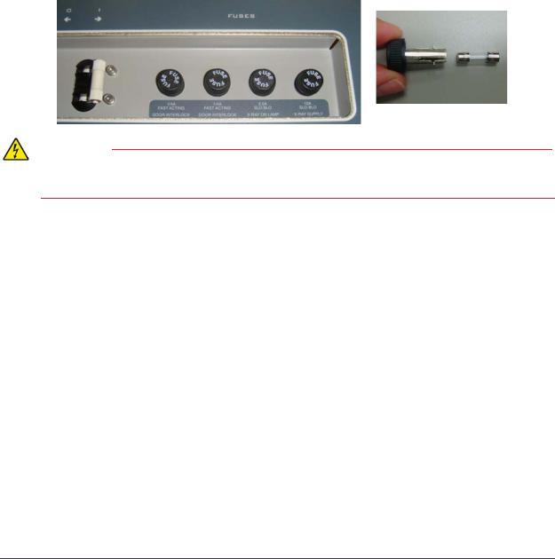
Replace External Fuses
Four external fuses are located on the back of the overhead.
WARNING
To avoid electrical shock, remove power from the system before removing fuses. Do not touch the metal parts of the fuse holder until fully removed from the system. Touch the plastic cap only.
1. |
Press the OFF button on the operator control box. The scanner shuts down and the POWER |
||||
|
indicators on the operator control box and scanner go OFF. |
||||
2. |
At rear of overhead, switch circuit breaker to off position. |
||||
3. |
Using plastic cap, turn fuse holder counterclockwise and pull out. |
||||
4. |
Replace the fuse in the holder. |
|
|
||
|
|
|
|
|
|
|
|
1, 2 |
Door Interlock |
0.25A, 250V (fast acting) |
|
|
|
|
|
|
|
|
|
3 |
Warning System |
2.5A, 250V (slow blow) |
|
|
|
|
|
|
|
|
|
4 |
X-Ray Power |
10A, 250V (slow blow) |
|
|
|
|
|
|
|
5. |
Align fuse holder in hole, push in and turn clockwise to secure. |
||||
032-0358-EN Rev B
1-1
Downloaded from www.Manualslib.com manuals search engine

Corrective Action
Panel Cover
The panel cover on the receptor panel fits very tightly over the panel. If this panel cover is removed and re-installed for any reason, perform the following:
•Crosshair Laser Adjustment
•Chair Calibration
•Centerline Laser Adjustment
•Geometric Calibration
Refer to the Installation Manual for instructions
Panel
Cover
032-0358-EN Rev B
1-2
Downloaded from www.Manualslib.com manuals search engine

Chapter |
Illustrated Parts Breakdown |
2 |
This chapter provides replacement part numbers. Ensure power is removed before servicing the scanner.
WARNING
High voltage is present in the scanner. Remove power from scanner before removing covers or cables. To avoid personal injury from electrical shock, do not operate the system with any covers open or cables removed.
To ensure power to the scanner is locked out from the main supply:
1.At rear of scanner, turn circuit breaker off.
2.Remove the overhead cord bracket.
3.Unplug the scanner line cord.
4.Re-install overhead cord bracket so that line cord cannot be
plugged in. |
3 |
2 |
1 |
The following assemblies are illustrated.
•System Assemblies (page 2-2)
•Overhead Assembly (page 2-4)
•Rotation Drive Assembly (page 2-6)
•X-Ray Source Assembly (page 2-8)
•Flip Receptor Panel Assembly (page 2-10)
•Chair Assembly (page 2-12)
•Upper Chair Assembly (page 2-14)
032-0358-EN Rev B
2-1
Downloaded from www.Manualslib.com manuals search engine
KaVo OP 3D Vision Service Manual
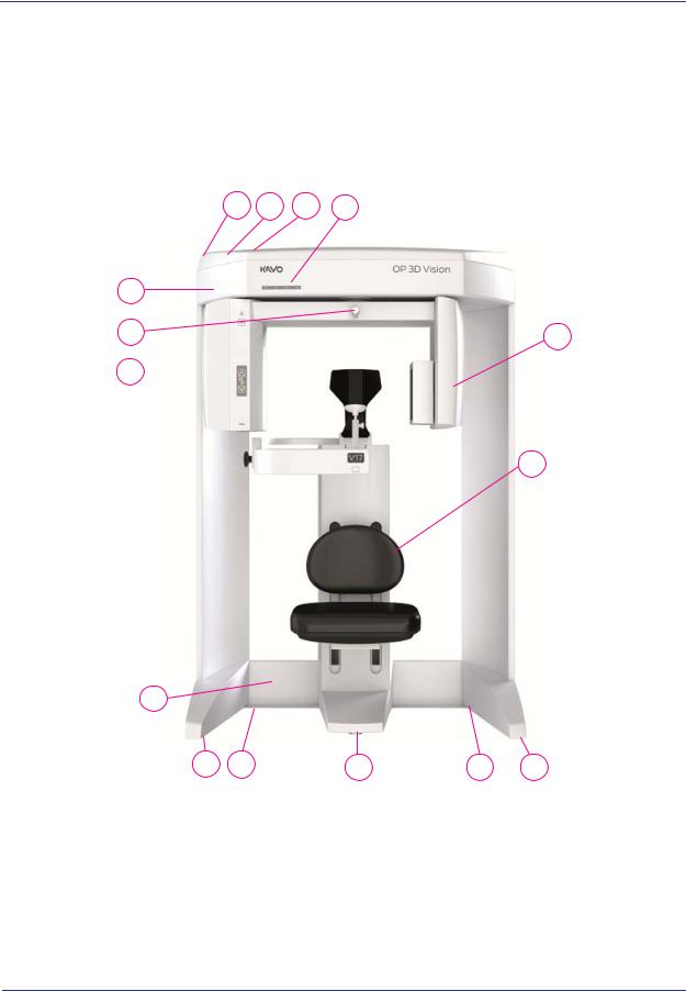
System Assemblies
1 |
2 |
3 |
4 |
13
12 |
5 |
11 
6
10
7 |
8 |
9 |
8 |
7 |
032-0358-EN Rev B
2-2
Downloaded from www.Manualslib.com manuals search engine

Illustrated Parts Breakdown
System Assembly Parts List
Item |
Part No. |
Description |
1 |
1.007.6265 |
Wall Stabilizer (not shown) |
2 |
1.006.5157 |
Upper Cover |
3 |
|
BHCS #8-32 x 3/8 Long |
4 |
1.013.0489 |
Resident Indicator Panel |
5 |
1.011.1964 |
Receptor Assembly |
6 |
1.013.1578 |
Chair Assembly |
7 |
1.011.4086 |
Leveler - 3/8-16 LG HX BC 1000# Cap |
8 |
0.830.0200 |
Leveler - 3/8-16 LG BC 1000# Cap |
9 |
1.011.4014 |
Leveler - 3/8-16 LG HX SL1000# Cap |
10 |
0.830.5669 |
Lower Plate Weldment |
11 |
1.011.1954 |
X-Ray Source Assembly |
12 |
1.007.4085 |
Laser Line Assembly |
13 |
1.013.0173 |
Lower Cover Assembly |
|
|
|
032-0358-EN Rev B
2-3
Downloaded from www.Manualslib.com manuals search engine

KaVo OP 3D Vision Service Manual
Overhead Assembly
30
29
28
27
26
|
25 |
|
24 |
|
23 |
|
22 |
|
21 |
|
20 |
|
19 |
15 |
18 |
15 |
17 |
1516
14
13
12
1
2
3
4
5
6
7
 8
8
 9
9
10
11
032-0358-EN Rev B
2-4
Downloaded from www.Manualslib.com manuals search engine
Illustrated Parts Breakdown
Overhead Assembly Parts List
Item |
Part No. |
Description |
1 |
1.006.3077 |
24V Power Supply |
2 |
0.830.0360 |
Hook and Loop Fastener |
3 |
|
#10-32 Nut |
4 |
1.006.3078 |
2520 Varian Power Supply |
5 |
0.830.0360 |
Hook and Loop Fastener |
6 |
|
#10-32 Nut |
7 |
1.007.1007 |
Limit Switches (set) |
8 |
0.830.2548 |
Spindle Assembly |
9 |
1.006.5842 |
Rotation Stepper Motor |
10 |
0.830.0457 |
Network Switch and Power Cable |
11 |
0.830.0360 |
Hook and Loop Fastener |
12 |
0.830.1997 |
Toroid Isolation Transformer |
13 |
|
SHCS 5/16-18 x 1 Long |
14 |
1.010.0953 |
Power Bracket Assembly |
15 |
1.007.4094 |
Buss #HTB-84M |
16 |
1.006.3075 |
10A Fuse Digi-Key #F985-ND |
17 |
1.006.3074 |
2.5A Fuse Digi-Key #F979-ND |
18 |
1.006.3076 |
0.25 A Fuse Digi-Key #F939-ND |
19 |
1.005.8617 |
10A/115VAC Circuit Breaker |
20 |
1.007.4095 |
Fuse Label (not shown) |
21 |
1.007.6324 |
Line Choke |
22 |
1.005.8629 |
Platform Motor |
23 |
1.007.6644 |
Ethernet Panel Mount Cable |
24 |
1.005.8632 |
System Board |
25 |
1.005.8624 |
Embedded Board |
26 |
1.007.4097 |
Warning System External Cable Assembly |
27 |
1.007.4098 |
Door Interlock External Cable Assembly |
28 |
1.007.4099 |
Control Box External Cable Assembly |
29 |
1.007.4100 |
Chair External Cable Assembly |
30 |
1.007.4101 |
Overhead Fan (pair) |
032-0358-EN Rev B
2-5
Downloaded from www.Manualslib.com manuals search engine

KaVo OP 3D Vision Service Manual
Rotation Drive Assembly
1 |
|
|
2 |
|
|
|
3 |
|
|
|
4 |
15 |
|
8 |
|
9 |
|
5 |
6 |
10 |
7 |
11
12
13
 14
14
032-0358-EN Rev B
2-6
Downloaded from www.Manualslib.com manuals search engine

Illustrated Parts Breakdown
Rotation Drive Assembly Parts List
Item |
Part No. |
Description |
1 |
|
SHCS #10-24 x 5/8 Long |
2 |
|
Split Washer #10 |
3 |
1.007.4102 |
Drive Gear |
4 |
1.006.8180 |
Gear Encoder Disk |
5 |
1.007.4105 |
Gear Clamp |
6 |
1.007.4106 |
Rotation Motor Bracket |
7 |
1.007.4107 |
Al. Round Spacer |
8 |
1.007.3996 |
Gear Encoder |
9 |
|
Split Washer #6 |
10 |
|
SHCS #6-32 x 1/2 Long |
11 |
1.005.8631 |
Stepper Motor |
12 |
1.007.5725 |
Thomson Micron #NTR23-025 |
13 |
|
Split Washer #10 |
14 |
|
SHCS #10-24 x 1/2 Long |
15 |
|
SHCS #10-24 x 3/4 Long |
|
|
|
032-0358-EN Rev B
2-7
Downloaded from www.Manualslib.com manuals search engine

KaVo OP 3D Vision Service Manual
X-Ray Source Assembly
1
2
6
7 8
3 4
5
9 10
11 |
12 |
13 |
|
|
14 |
||
|
|
||
|
|
|
15 |
16 |
17 |
|
|
|
18 |
|
||
|
|
19 |
||
|
|
|
||
|
|
|
|
032-0358-EN Rev B
2-8
Downloaded from www.Manualslib.com manuals search engine

|
|
|
Illustrated Parts Breakdown |
|
|
|
|
|
|
X-Ray Source Assembly Parts List |
||||
|
|
|
|
|
|
Item |
Part No. |
Description |
|
|
1 |
0.830.4966 |
Rear X-Ray Source Cover Assembly |
|
|
2 |
|
BHCS #8-32 x 1/2 Long |
|
|
3 |
|
SHCS 1/4-20 x 1 Long |
|
|
4 |
|
Split Washer 1/4 |
|
|
5 |
1.005.8633 |
Tube Head Assembly |
|
|
6 |
1.005.8622 |
Cross Laser Assembly |
|
|
7 |
0.830.0492 |
Cross Laser Mirror |
|
|
8 |
|
BHCS #6-32 x 1/4 Long |
|
|
9 |
|
Split Washer #10 |
|
|
10 |
|
SHCS #10-24 x 3/8 Long |
|
|
11 |
1.010.9900 |
Beam Limiter |
|
|
12 |
1.013.0493 |
Patient Align Panel |
|
|
13 |
0.830.4965 |
Front X-Ray Source Cover Assembly |
|
|
14 |
1.006.5158 |
Beam Limiter Panel |
|
|
15 |
1.006.3236 |
Beam Limiter Control PCB |
|
|
16 |
1.007.4110 |
#6-32 x 1/2 Long Standoff McMaster #91 |
|
|
17 |
1.007.6278 |
Beam Limiter Board Shield |
|
|
18 |
|
Split Washer #6 |
|
|
19 |
|
SHCS #6-32 x 1/4 Long |
|
|
|
|
|
|
032-0358-EN Rev B
2-9
Downloaded from www.Manualslib.com manuals search engine
KaVo OP 3D Vision Service Manual
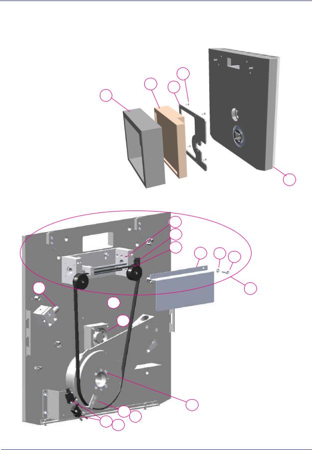
Flip Receptor Panel Assembly
Panel Side
2
1
6
14 
15
16 17
18 19
4
3
5
8
9
10
11 12 13
7
Panel
Drive Side
20
032-0358-EN Rev B
2-10
Downloaded from www.Manualslib.com manuals search engine

Illustrated Parts Breakdown
Flip Receptor Panel Assembly Parts List
Item |
Part No. |
Description |
1 |
1.009.9646 |
Cover, Receptor Panel |
2 |
1.009.9456 |
2520DX Receptor Panel |
3 |
0.830.0627 |
Mounting Plate, Receptor 2520D |
4 |
|
Flat Soc. Hd. M5 |
5 |
1.011.1955 |
Rear Receptor Cover Assy |
6 |
1.007.4114 |
Stop Screw |
7 |
1.007.4001 |
Drive Screw Assembly |
8 |
|
SHCS M3 x 8mm Long |
9 |
1.005.8630 |
Flip Stepper Motor |
10 |
1.007.4003 |
Idler |
11 |
1.007.4115 |
Cable Shield |
12 |
|
Split Washer #10 |
13 |
|
SHCS #10-32 x 5/8 Long |
14 |
1.007.4116 |
Belt McMaster #6484K511 |
15 |
0.830.0778 |
Flip Receptor Fan |
16 |
1.007.4005 |
Belt Key |
17 |
|
Flat Head Screw #8-32 x 3/8 Long |
18 |
1.007.4007 |
Flip Receptor Limit Switch Assembly |
19 |
|
SHCS #4-40 x 5/8 Long |
20 |
|
SHCS #10-32 x 3 1/2 Long |
|
|
|
032-0358-EN Rev B
2-11
Downloaded from www.Manualslib.com manuals search engine
 Loading...