

Page 1

ORTHOPANTOMOGRAPH™ OP 3D
Service manual
ENGLISH
215241 rev. 4
0.805.4918
Page 2

Page 3

Contents
1 Disclaimer................................................................... 6
2 Introduction................................................................ 7
2.1 ORTHOPANTOMOGRAPH™ OP 3D............................................................. 7
2.2 Intended use......................................................................................... 7
2.3 Abbreviations......................................................................................... 7
2.4 Disposal and recycling............................................................................ 8
2.5 Associated documentation....................................................................... 8
3 Safety..........................................................................9
3.1 Service precautions and warnings.............................................................9
3.1.1 Signal words...............................................................................9
3.1.2 General servicing precautions........................................................9
3.1.3 Electrical safety........................................................................... 9
3.1.4 Electrostatic discharge................................................................10
3.1.5 Device modifications during service..............................................10
3.1.6 Radiation safety.........................................................................10
3.1.7 Symbols that may appear on the device or its parts....................... 11
4 Device description.....................................................13
4.1 Mechanical description...........................................................................13
4.1.1 Main parts................................................................................ 13
4.1.2 Device movements.....................................................................14
4.1.3 Device covers............................................................................14
4.1.4 Status indicator light.................................................................. 15
4.1.5 Device labels.............................................................................16
4.1.6 Emergency stop switch...............................................................16
4.2 Device software....................................................................................17
4.2.1 Firmware overview.....................................................................17
4.2.2 Firmware update....................................................................... 17
4.3 Electrical description............................................................................. 19
4.3.1 Circuit board locations................................................................19
4.3.2 Circuit boards overview.............................................................. 19
4.3.3 Position control..........................................................................20
4.3.4 Exposure logic........................................................................... 20
4.3.5 Power supply.............................................................................20
4.3.6 Fuses....................................................................................... 21
4.4 User Interfaces.....................................................................................22
4.4.1 Graphical User Interface (GUI).................................................... 22
4.4.2 Positioning panel....................................................................... 33
4.5 Circuit boards.......................................................................................34
4.5.1 i2000 image capture board......................................................... 34
4.5.2 i3000 Main control board............................................................ 37
4.5.3 i4000 power supply board.......................................................... 40
4.5.4 i4100 back panel board.............................................................. 42
4.5.5 i6000 user interface board..........................................................42
4.5.6 i8000 LED indicator board.......................................................... 42
4.5.7 i9000 chin rest sensor board.......................................................44
ORTHOPANTOMOGRAPH™ OP 3D 3
Page 4

5 Diagrams...................................................................45
5.1 Wiring diagram.....................................................................................45
5.2 Fusing diagram.....................................................................................47
5.3 Emergency stop....................................................................................47
5.4 Mains voltage distribution...................................................................... 47
5.5 Power distribution +24Vdc..................................................................... 48
5.6 Ethernet communication........................................................................ 48
5.7 CAN communication.............................................................................. 48
5.8 i2C self diagnosis communication........................................................... 49
5.9 Rotation movement...............................................................................49
5.10 Linear movement................................................................................ 50
5.11 Pivot movement..................................................................................50
5.12 Z movement...................................................................................... 51
5.13 Collimator movements......................................................................... 51
5.14 Positioning lights.................................................................................52
5.15 Imaging chain 3D............................................................................... 52
5.16 Exposure control 1..............................................................................53
5.17 Exposure control 2..............................................................................53
5.18 Exposure warning light........................................................................ 54
5.19 Device control panel............................................................................54
5.20 Chin rest detection..............................................................................55
6 Maintenance..............................................................56
6.1 Annual maintenance..............................................................................56
6.1.1 Cleanliness of the device............................................................ 56
6.1.2 Condition of the cables...............................................................56
6.1.3 Device movements and functionality............................................ 57
6.1.4 Exposure indicator functionality................................................... 58
6.1.5 Changing the fuses.................................................................... 59
6.1.6 Monitor calibration..................................................................... 59
6.2 Calibrations.......................................................................................... 60
6.2.1 When to calibrate the device....................................................... 60
7 Troubleshooting........................................................ 62
7.1 Initial actions....................................................................................... 62
7.1.1 Error codes............................................................................... 62
7.1.2 Acknowledging errors................................................................. 62
7.1.3 Image transfer.......................................................................... 62
7.2 List of error codes................................................................................ 63
8 Part replacement instructions................................. 100
8.1 Before replacing parts......................................................................... 100
8.2 Removing the covers........................................................................... 100
8.2.1 Disconnecting power supply...................................................... 100
8.2.2 Removing upper shelf covers.....................................................100
8.2.3 Removing the carriage covers....................................................102
8.2.4 Removing the rotating unit covers..............................................107
8.2.5 Removing the lower shelf covers................................................111
8.3 Replacing parts................................................................................... 113
8.3.1 Disconnecting and connecting the cables.....................................113
8.3.2 Replacing the PAN/3D sensor.................................................... 113
8.3.3 Replacing the horizontal lasers.................................................. 116
8.3.4 Replacing the i4000 power supply board..................................... 120
8.3.5 Replacing the carriage cable set.................................................122
4 ORTHOPANTOMOGRAPH™ OP 3D
Page 5

8.3.6 Replacing the main cable set..................................................... 125
8.3.7 Replacing the i2000 image capture board....................................128
8.3.8 Replacing the i3000 main control board...................................... 129
8.3.9 Replacing the tube head........................................................... 130
8.3.10 Replacing the lower shelf upper cover assembly......................... 134
8.3.11 Replacing the collimator.......................................................... 137
8.3.12 Removing the upper shelf plate................................................140
8.3.13 Replacing the linear and pivot movement and motor................... 140
8.3.14 Replacing the speaker with cable............................................. 145
8.3.15 Replacing the firmware card.................................................... 146
8.3.16 Replacing the emergency stop switch with cable......................... 147
8.3.17 Replacing the i8000 LED indicator board................................... 147
8.3.18 Replacing the i4100 back panel board.......................................148
8.3.19 Replacing the mains switch..................................................... 149
8.3.20 Replacing the pivot and linear movement sensors....................... 150
8.3.21 Replacing the linear movement sensor wiper..............................152
8.4 After service work...............................................................................152
8.5 Safety tests for maintenance................................................................153
8.5.1 Introduction............................................................................ 153
8.5.2 Warnings and precautions......................................................... 153
8.5.3 Measurement equipment...........................................................153
8.5.4 Protective earth resistance test..................................................153
8.5.5 Measuring protective earth........................................................154
ORTHOPANTOMOGRAPH™ OP 3D 5
Page 6

1 Disclaimer
1 Disclaimer
ORTHOPANTOMOGRAPH™ OP 3D Service manual, 215241 r4.
Copyright © 2017 by PaloDEx Group Oy. All rights reserved.
ORTHOPANTOMOGRAPH™, OP™, ORTHOselect™, QUICKcompose™, SMARTview™,
ORTHOfocus™ and Low Dose Technology™ are either registered trademarks or
trademarks of KaVo Kerr Group Finland in the United States and/or other countries.
KaVo™ is either registered trademark or trademark of Kaltenbach & Voigt GmbH in the
United States and/or other countries.
All other trademarks are property of their respective owners.
Documentation, trademark and the software are copyrighted with all rights reserved.
Under the copyright laws the documentation may not be copied, photocopied,
reproduced, translated, or reduced to any electronic medium or machine-readable form
in whole or part, without the prior written permission of PaloDEx Group Oy.
The original language of this manual is English, code 215241 rev 2. In a case of
interpretation disagreement the English text is applied.
PaloDEx Group Oy reserves the right to make changes in specification and features
shown herein, or discontinue the product described at any time without notice or
obligation. Contact your PaloDEx Group Oy representative for the most current
information.
The manufacturer has no liability for consequential damage, personal injury, loss,
damage or expense directly or indirectly caused by the use of the product. No agent,
distributor or other party is authorized to give warranty or other liability on behalf of the
manufacturer with respect to its products.
Manufacturer:
PaloDEx Group Oy
Nahkelantie 160
FI-04300 Tuusula
FINLAND
Tel. +358 10 270 2000
www.kavokerrgroup.com
6 ORTHOPANTOMOGRAPH™ OP 3D
Page 7

2 Introduction
2 Introduction
2.1 ORTHOPANTOMOGRAPH™ OP 3D
The ORTHOPANTOMOGRAPH™ OP 3D (later called device) is a dental X-ray device
producing high quality digital images of dentition, TM-joints and skull. To take images,
you need a suitable workstation connected to the device and a dental imaging software
to capture and manage the images.
The ORTHOPANTOMOGRAPH™ OP 3D can be used for the following procedures:
Panoramic Imaging
• Standard Panoramic
• Segmented Panoramic
• Pediatric Panoramic
• Bitewing
• TMJ, lateral projection
3D CBCT Imaging
Volume Height x Diameter (H x D)
• 5 x 5 cm; implant and other single tooth imaging
• 6 x 9 cm; single jaw imaging
• 9 x 11 cm; whole dental area imaging (both jaws)
• 9 x 14 cm (optional); both jaws including TMJ
• FOV position and height fine-tuning is possible according to scout images
CAUTION! USA only: Federal law restricts this device to sale by or on the order
of a dentist or other qualified professional.
2.2 Intended use
ORTHOPANTOMOGRAPH™ OP 3D is an X-ray device that is configured to take panoramic
and 3D images of the cranio-maxillofacial complex for use in diagnostic support.
ORTHOPANTOMOGRAPH™ OP 3D must only be used and operated by dentist and other
qualified professionals.
2.3 Abbreviations
PCBA Printed Circuit Board Assembly
THA Tube Head Assembly
GUI Graphical User Interface
EMI Electromagnetic Interference
ESD Electrostatic Discharge
DUT Device Under Test
ORTHOPANTOMOGRAPH™ OP 3D 7
Page 8

2 Introduction
2.4 Disposal and recycling
The device and its components are lead-free, including its radiation protection
components. The device meets the RoHS Directive 2011/65/EU, WITHOUT any
exemptions mentioned in Annex IV.
At least the following parts of the device should be re-cycled according to local and
national regulations regarding disposal of non-environmentally friendly materials:
• Tubehead (oil)
• All electronic circuits and electronic boards
• Plastic parts
2.5 Associated documentation
• ORTHOPANTOMOGRAPH™ OP 3D User and Installation Manual
• Dental imaging software documentation
• ORTHOPANTOMOGRAPH™ OP 3D Sparepart Catalogue.
8 ORTHOPANTOMOGRAPH™ OP 3D
Page 9

3 Safety
3 Safety
3.1 Service precautions and warnings
3.1.1 Signal words
The following signal words and labels are used in this document:
WARNING! Indicates a hazardous situation which, if not avoided, could result in
death or serious injury.
CAUTION! Indicates a hazardous situation which, if not avoided, could result in
minor or moderate injury.
NOTICE! Highlights suggestions which will result in enhanced installation,
reliability, or operation. Not used for safety related hazards.
3.1.2 General servicing precautions
CAUTION! Only trained and qualified service persons authorized by the
manufacturer of the device are allowed to service the device.
• Use only the original spare parts that are provided by the manufacturer when you
repair the device or replace any parts in it.
• Before you attempt to service the device make sure that you know how to operate it.
Read the ORTHOPANTHOMOGRAPH OP 3D User and Installation Manual.
• Attach the covers before you hand over the device after service.
• Ensure the electrical safety of the device by inspecting the proper grounding of user
touchable metallic parts before handing the device to the user.
• Clean the device from dust.
• Attach and tighten all screws that have been removed or loosened during service
work.
• Check the tightness of the screws in the device, especially in the carriage and the wall
mount.
• For connection requirements and safety, see the Connection requirements section in
the User manual.
• Read and understand the warnings and precautions listed in the following sections of
this service manual and in the User and Installation manual.
3.1.3 Electrical safety
• Disconnect the device from the main power supply before repairing or replacing any
mechnical parts, circuit boards or installing accessories.
• Disconnect the device from the main power supply before removing the covers.
• Disconnect the device from the main power supply before replacing circuit boards or
other electrical components.
• The circuit boards and electrical components of the device can contain capacitors with
high voltages. Wait ten (10) minutes, after disconnecting the device from the power
supply, before handling the board or component.
• If you have to leave the device unattended during service or maintenance, disconnect
the device from main power supply to protect people, who may touch the device, from
electric shock.
• The device must only be used in areas that are provided with a protective earth
connection to ensure an equipotential ground connection.
• Assemble the device according to the instructions in User and Installation manual,
always use the correct materials and original spare parts.
ORTHOPANTOMOGRAPH™ OP 3D 9
Page 10

3 Safety
Do not compromise:
• EMI enclosures and tightness of cases and screw contacts
• Gaskets
• Cable shields and their grounding to the chassis
• Electromagnetic immunity by incorrect cabling.
3.1.4 Electrostatic discharge
Electrostatic Discharge (ESD) can damage or destroy electronic components.
When you service the device take precautions to avoid electrostatic charge to build up
and discharge (ESD). Follow the local and national recommendations for the prevention
of ESD. If no recommendations are available, follow the guidelines below:
• Leave all new or replacement circuit boards and electrical parts in their protective
packaging until the boards are needed.
• Before handling circuit boards and electrical parts make sure that any static electricity
charge that has built up in your body is discharged.
• When examining and checking circuit boards use an antistatic wrist wrap which is
connected to a ground point through a 1 Mohm current limiting cable. Also use a cable
to connect the device to the same ground potential as the wrist wrap.
• When handling circuit boards hold them by their edges and do not touch any
components or connectors.
• If an antistatic mat is used, connect the wrist wrap to the mat and the mat to the
ground potential.
• To make sure that the wrist wrap is in good condition, check and wash it frequently.
3.1.5 Device modifications during service
CAUTION! Only authorized service technicians are allowed to service,
install and replace parts of the device.
CAUTION! Only approved spareparts supplied by the manufacturer are allowed
to be used.
CAUTION! Make sure that any modifications done to the device do not degrade
the EMC performance of the device.
• Never make unauthorized changes or modifications to the device or its parts.
• Never dismantle or remanufacture any part of the tube head assembly or beam
limiting device.
• Never adjust any part of the beam limiting device unless under the direction of the
manufacturer.
• Ensure that the EMC performance of the device is not degraded when the device is
upgraded, serviced and repaired.
NOTICE! Ensure that the EMC performance is not degraded thoughout the whole
service life of the device.
3.1.6 Radiation safety
CAUTION! When you take test exposures, take adequate precautions to protect
youself from radiation. Stand behind a suitable radiation shield that is positioned
at least two meters from the device.
10 ORTHOPANTOMOGRAPH™ OP 3D
Page 11
3 Safety
Before you use or service the device familiarize yourself with local and national radiation
safety standards and requirements relating to dental x-ray equipment.
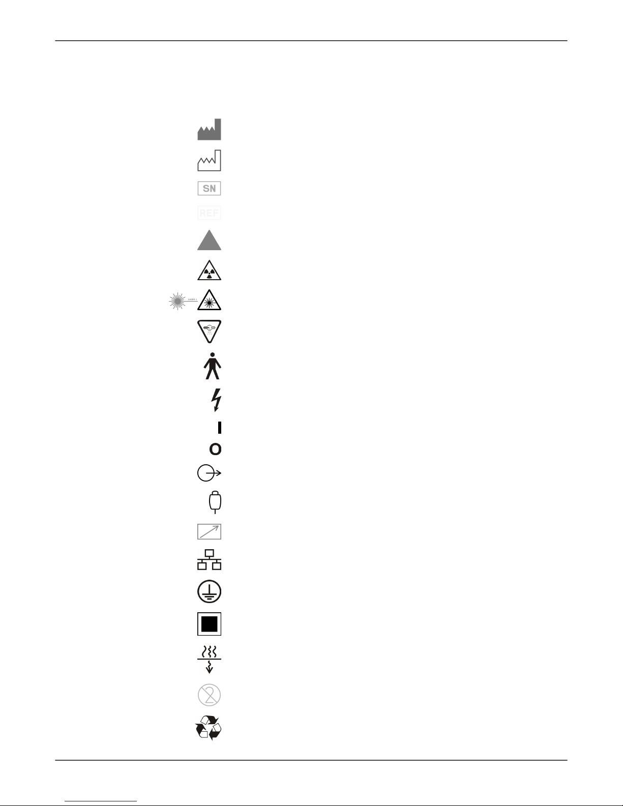
3.1.7 Symbols that may appear on the device or its parts
Manufacturer
Date of manufacture
Serial number
Catalog or model number
Caution
Radiation warning
Laser warning
Radiation emitting device
Type B Applied part
Dangerous voltage
On or enabled
Off or disabled
External warning light
Exposure switch
Remote exposure switch
Ethernet
Protective earth (ground)
Focal spot
Total X-ray filtration
Do not reuse
Recyclable
ORTHOPANTOMOGRAPH™ OP 3D 11
Page 12
3 Safety
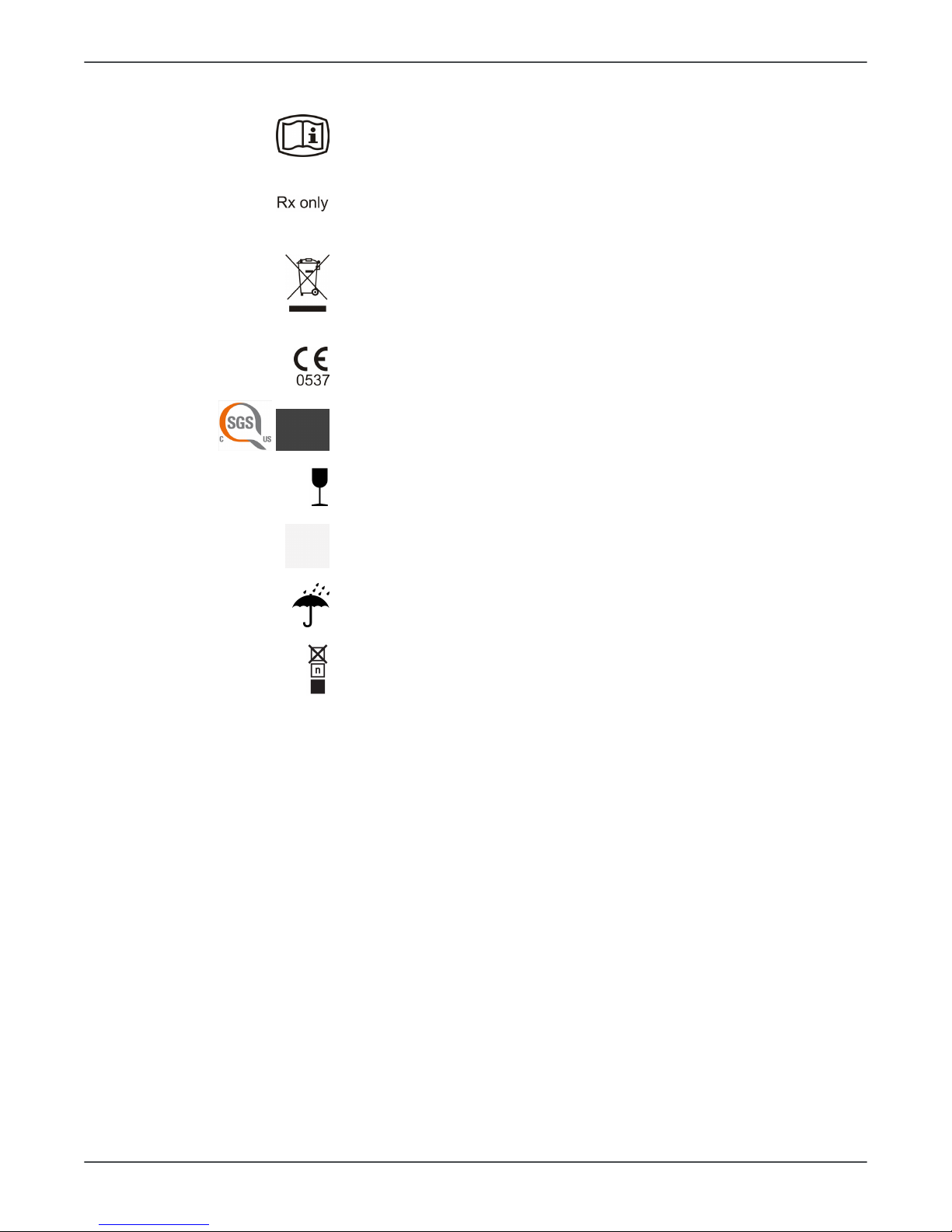
Operating instructions
Refer to operating instructions for more information. The
operating instructions can be supplied electronically or in
paper format.
Caution: Federal law restricts this device to sale by or on the
order of a licensed healthcare practitioner.
This symbol indicates that the waste of electrical and
electronic equipment must not be disposed as unsorted
municipal waste and must be collected separately. Please
contact an authorized representative of the manufacturer
for information concerning the decommissioning of your
equipment.
CE (0537) symbol
NRTL Mark
Conforms to AAMI ES60601-1:2006. Certified to CSA.
Fragile, Handle with Care (Packaging)
This way up (Packaging)
Keep dry (Packaging)
Maximum number of boxes that can be stacked on the
bottom box (Packaging)
12 ORTHOPANTOMOGRAPH™ OP 3D
Page 13
4 Device description
4 Device description
4.1 Mechanical description
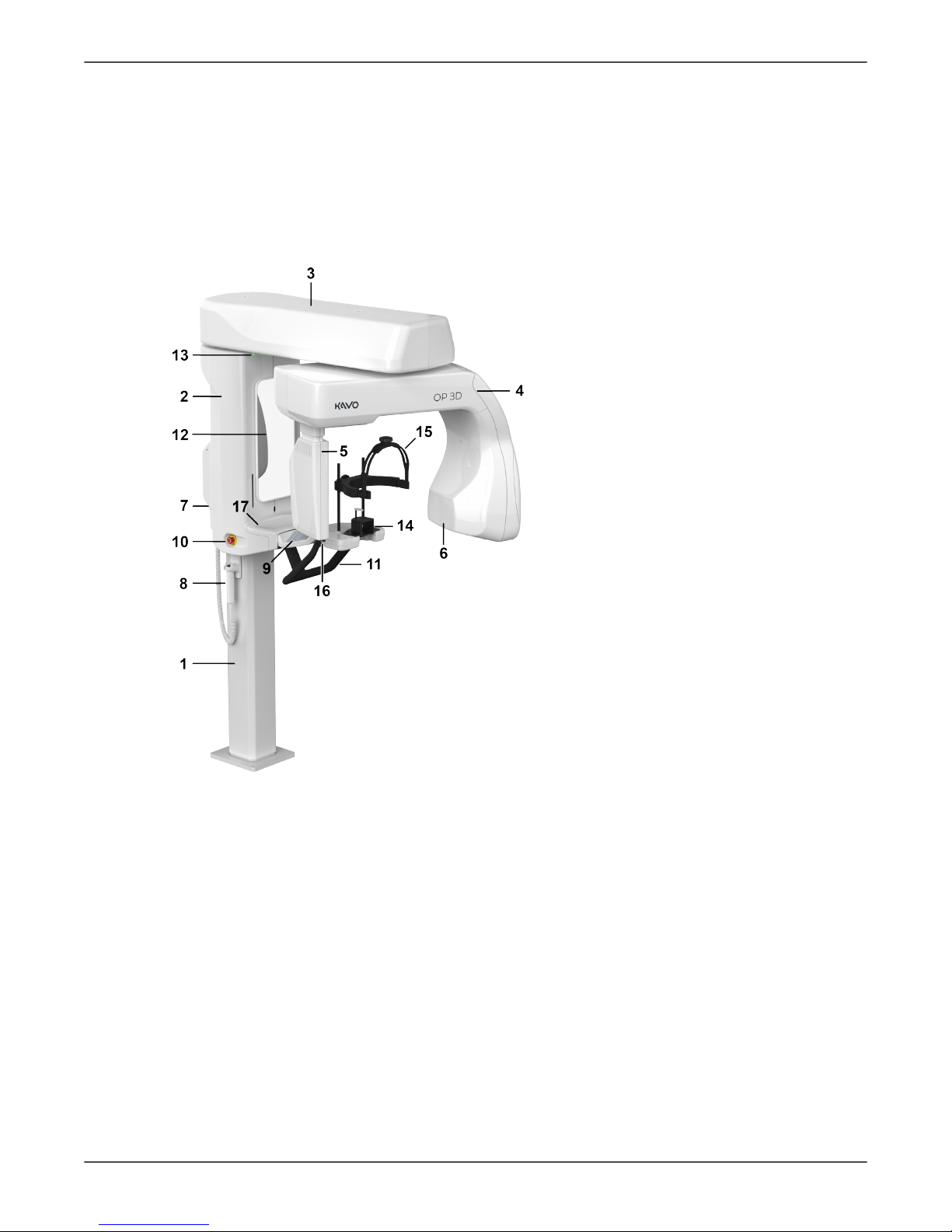
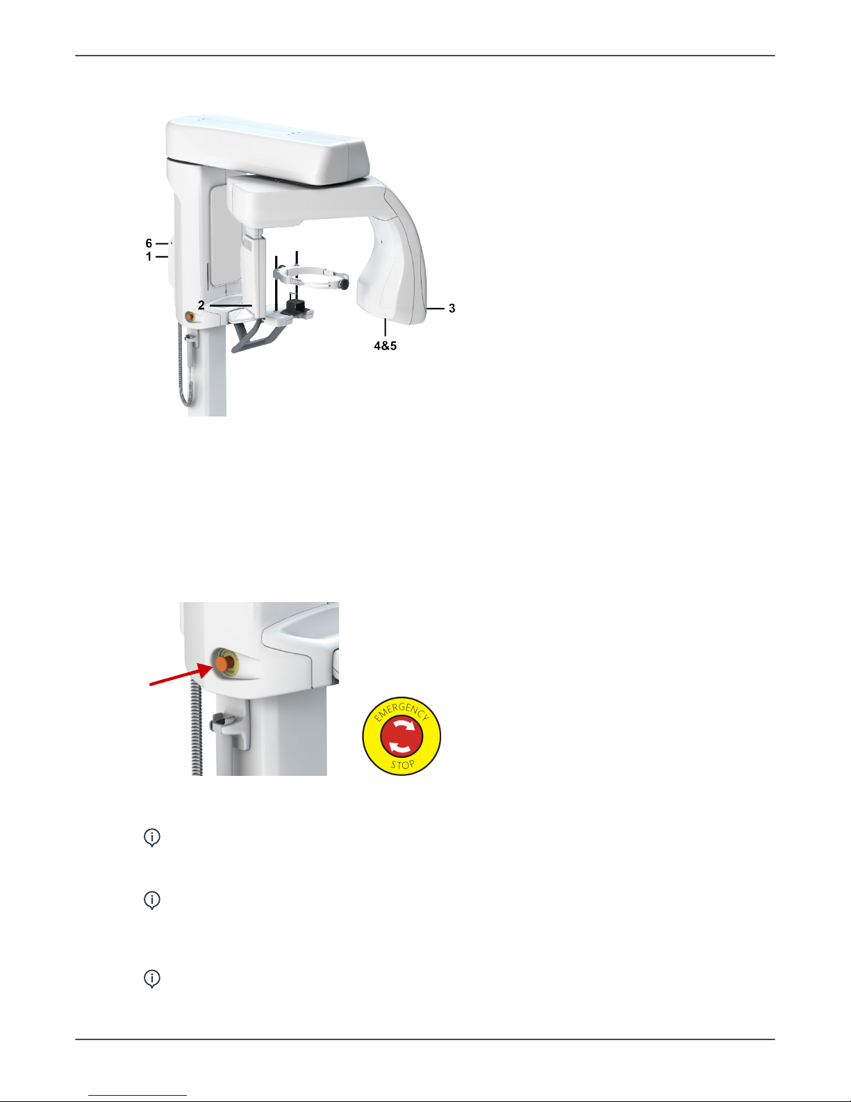
4.1.1 Main parts
1. Column
2. Carriage
3. Upper shelf
4. Rotating unit
5. Sensor
6. Tubehead
7. Power switch (Back of
the device)
8. Exposure switch
9. Positioning panel
10. Emergency stop switch
11. Patient handles
12. Mirror
13. Status indicator light
14. Chin rest
15. Head support
16. Head support locking
lever
17. Lower shelf tray
ORTHOPANTOMOGRAPH™ OP 3D 13
Page 14
4 Device description
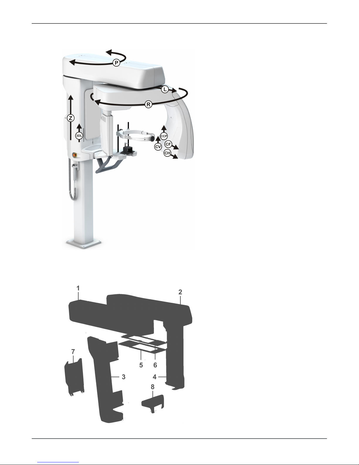
4.1.2 Device movements
Z - Column UP/DOWN movement
P - Pivot movement of the upper
shelf
L - Linear movement of the
rotating unit
R - Rotating movement of the
rotating unit
CV - Vertical movement of the
collimator plate
CH - Horizontal movement of the
collimator plate
CF - Collimator filter movement
3DL - 3D Horizontal and PAN FH
Laser movement
CCP - Child collimator plate
movement (Panoramic only)
4.1.3 Device covers
Carriage covers
1 Upper shelf cover left
2 Upper shelf cover right
3 Carriage side cover left
4 Carriage side cover right
5 Finger shield plate 1
6 Finger shield plate 2
7 Back panel cover
8 Lower shelf tray
14 ORTHOPANTOMOGRAPH™ OP 3D
Page 15
4 Device description
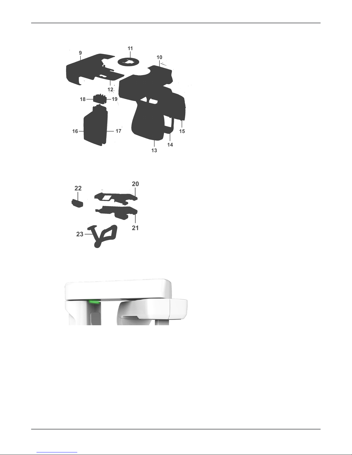
Rotating unit covers
9 Rotator back cover
10 Rotator front cover
11 Rotator finger protection
upper
12 Rotator finger protection
lower
13 Tube head front cover
14 Tube head back cover
15 Tube head plate
16 3D sensor back cover
17 3D sensor front cover
18 Outer sensor collar cover
19 Inner sensor collar cover
Lower shelf covers
20 Lower shelf cover set with
control panel
21 Lower shelf bottom cover set
22 Layer laser cover assembly
23 Patient handle
4.1.4 Status indicator light
Device status indicator light, located on the top of the carriage, illuminates according the
device status:
• YELLOW: Device is radiating.
• BLUE: Device is in error state or pending user action. Check the GUI for details.
• BLUE (blinking): Press HOME button or no EHT connection.
• GREEN: Device is ready for imaging.
• GRAY: Power down mode. Device is not ready for imaging, follow the instructions on
the status message bar
ORTHOPANTOMOGRAPH™ OP 3D 15
Page 16
4 Device description
4.1.5 Device labels
1. Type label
2. Sensor label
3. THA label
4. Collimator label
5. Filtration label
6. Warning label
4.1.6 Emergency stop switch
An emergency stop switch is located on the left side of the carriage.
Pressing the emergency stop switch immediately terminates the imaging and all device
movements and resets all circuit boards.
NOTICE! An interrupted imaging process cannot be resumed. A new image needs
to be taken.
To release the emergency stop switch, rotate it clockwise.
NOTICE! Make sure that the emergency stop switch is not pressed down when
you start the imaging process.
The Graphical User Interface (GUI) has indication if the emergency stop is active and the
device status indication lights are blue.
NOTICE! Activating the emergency stop causes the device to restart.
16 ORTHOPANTOMOGRAPH™ OP 3D
Page 17

4 Device description
4.2 Device software
4.2.1 Firmware overview
Firmware description
The device firmware (FW) consists of board and processor component specific binary
files, that are loaded on various system board locations.
NOTICE! The device Firmware versions can be found under the System info on
the Settings menu on the GUI.
The device components communicate via CAN buses and other interfaces.
The FW system is split into four main areas:
1. Real time operations
2. Image data capturing
3. General functions
4. GUI client
The main control functions are located in different parts of the system:
• PCBA i4000: Controls generator, tube head, column
• PCBA i3000: Controls pivot and linear movement
• PCBA i2000: Controls image capturing hardware, rotating unit movement
Non-time critical tasks are handled by the main application controlling the overall
operations. The main application includes, for example:
• graphical user interface
• interfaces to modality SW
• device data storage
• device reservation.
The device has a remote Graphical User Interface (GUI) which is interfaced over
Ethernet. The i3000 board includes a SD-card for the permanent storage of data.
4.2.2 Firmware update
The firmware update can be performed through the device GUI. See chapter Settings
menu.
NOTICE! You can update the firmware only in the Service menu.
To update the firmware, do the following:
1. Download the firmware distribution package.
NOTICE! The package is named in format OP3D-FW_x_x_x_216403D519721-y.zip where the x_x_x indicates the firmware version.
2. Unzip the firmware distribution package to the hard drive of the workstation
connected to the device.
3. Ensure that the workstation software and drivers are up to date so that they meet
the requirement of the firmware release.
4. Update SW and drivers, if needed.
5. Browse to Settings> Service menu.
ORTHOPANTOMOGRAPH™ OP 3D 17
Page 18
4 Device description
6. Enter PIN code 1917 to access the Service menu.
7. Browse to Service> FW Update.
8. Click Select File and browse to the location to the firmware file to be loaded, for
example C:\temp\OP_3D_EMBEDDED_SOFTWARE_Rx_y_z_abcd.tar.gz. Select the
update file.
9. Click Start Update.
10. Wait for the update to finish.
11. Close the GUI to disconnect the device from the imaging software.
12. Re-connect the device by using the imaging software to finalize the update.
13. Perform all the device calibrations in accordance to the calibrations procedure, refer
to Complete device calibration chapter of the OP 3D User and Installation manual.
18 ORTHOPANTOMOGRAPH™ OP 3D
Page 19
4 Device description
4.3 Electrical description
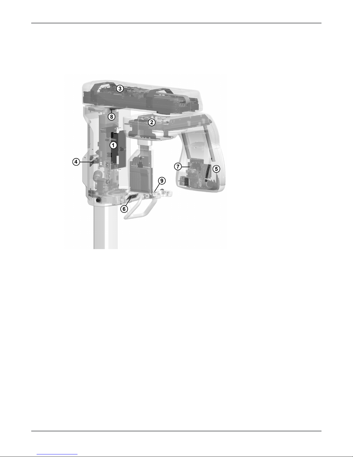
4.3.1 Circuit board locations
1. i4000 Power Supply
board
2. i2000 Image Capture
Board
3. i3000 Main Control
Board
4. i4100 Back panel
board
5. i5000 Cascade board
(in the Tubehead
assembly)
6. i6000 User interface
board
7. i7000 Tubehead
interface board (in the
Tubehead assembly)
8. i8000 LED indicator
board
9. i9000 Chin rest
sensor board
4.3.2 Circuit boards overview
The OP 3D HW structure is based on three main electrical boards. Each board
implements certain control functions, such as exposure control and motion control, and
they interact with each other through the communication buses.
The main boards are:
i2000 Image Capture Board
i3000 Main Control Board
i4000 Power Supply board
The device also contains seven smaller boards:
i4100 Back panel board
i5000 Cascade board (part of the tube head)
i6000 User interface board
i7000 Tubehead interface board (part of the tube head)
i8000 LED indicator board
i9000 Chin rest sensor board
ORTHOPANTOMOGRAPH™ OP 3D 19
Page 20

4 Device description
For further information on the boards, see the relevant sections in this document.
4.3.3 Position control
Positioning of the device is done by stepper- and DC-motors, using feedback from
optical, resistive and Hall sensors. The control chain per actuator is described below.
Upper shelf linear and pivot movement, rotator movement
The movement is driven by a stepper motor. A resistive sensor determines the
approximate position of the actuator. A number of exact positions is determine by
matching the approximate position with feedback from an optical sensor changing state
at regular intervals. Positioning between these points is based on by counting steps fed
to the stepper motor.
Lasers and collimator movement
The movement is driven by a stepper motor. An optical sensor is used to determine the
Home position. Driving to wanted position is done by first finding the Home position, and
then counting steps fed to the stepper motor.
Z-movement
The movement is driven by a DC motor. An optical sensor is used to determine the Home
position. The Z-position is determined by using the home position as reference and
counting pulses generated by a Hall sensor connected to the motor.
Imaging chain overview / Image data transfer
Image capturing is handled by the i2000 Image Capture Board. This board is responsible
for both triggering the sensor and capturing image data. The data is stored in the i2000
Image Capture Board until transferred through the I3000 board to the image capturing
workstation.
4.3.4 Exposure logic
Exposure logic is solely controlled by i4000 board. The i4000 board includes power
supply, inverter and filament power supply that are responsible for supplying the X-ray
tube head.
Filament pre-heat
Prior the high voltage generation at the tube head the filament is pre-heated. The preheating process is controlled and monitored by the i4000 board.
Exposure
After the filament pre-heat, the exposure is enabled. Exposure is monitored by the i4000
board by utilizing the KVFB and MAFB signals and comparing them against the selected
reference signals.
Backup timer
The exposure timing is controlled by the firmware. In the event of malfunction there
is an added safety timer implemented in hardware, which will cut the exposure in case
EXPENA-signal is active too long.
4.3.5 Power supply
The mains power supply comes from the wall socket through the back panel to the i4100
board. For further information, see i4100 back panel board en la página 42. See also
Power distribution +24Vdc en la página 48.
Mains power configuration
Detach the indicated screw on the back panel cover and lift it off to access the device
back panel.
20 ORTHOPANTOMOGRAPH™ OP 3D
Page 21

4 Device description
Refer to User and Installation manual, chapter Mains power configuration for detailed
instructions.
NOTICE! In i4100 back panel board there is a switch (SW1) that is used for
changing, for example, from permanent to plug connection. Refer to User and
Installation manua, chapter Mains power configuration.
4.3.6 Fuses
The allowed main fuse types are listed in the table below. See also Fusing diagram.
Table 1: Main fuses
Location Ref Value Type
i4100
220-240Vac
(6.3x32mm)
Littelfuse 215 (Time-Lag) 10A
Cooper Bussman (Time Delay)
S505H-10-R
Back panel
F1 & F2
100-120Vac
(6.3x32mm)
Littelfuse 326 (SlowBlow) 15A
Cooper Bussman (Time Delay)
MDA-15
External warning light
fuse (i4100)
F3 Cooper Bussmann (Time Delay)
S506-2-R
For fuses in circuit boards, see:
i2000 image capture board
i3000 Main control board
i4000 power supply board
ORTHOPANTOMOGRAPH™ OP 3D 21
Page 22
4 Device description
4.4 User Interfaces
4.4.1 Graphical User Interface (GUI)
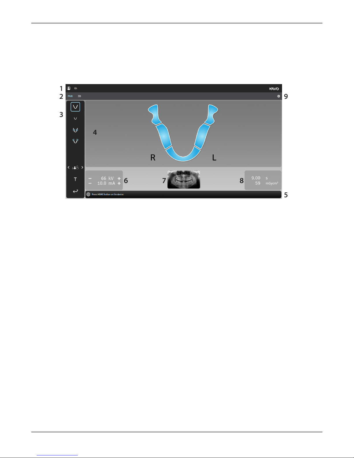
GUI Overview
1. Selected patient name and Patient Identification (ID).
2. Selection of imaging modality, PAN or 3D.
3. Imaging program settings.
4. Main view area. Shows a dental chart for the selected modality and previews of the
taken images.
5. Status message bar shows the device status and provides messages and instructions
to the user. Click on the bar to show messages if there are more than the ones
shown.
6. Imaging parameters. Imaging parameters, kV (PAN only) and mA, can be manually
adjusted according to the patient size and skull anatomy using the - & + icons.
7. Sample image of the selected Panoramic program or 3D FOV size and location
illustration.
8. Scan time and DAP display. Shows the duration of X-ray radiation and the dose
production with the selected imaging program and parameters.
9. Device settings. Opens a menu which is used to access the device settings, quality
control and calibration programs and to show the device information, like serial
number and software versions.
22 ORTHOPANTOMOGRAPH™ OP 3D
Page 23
4 Device description
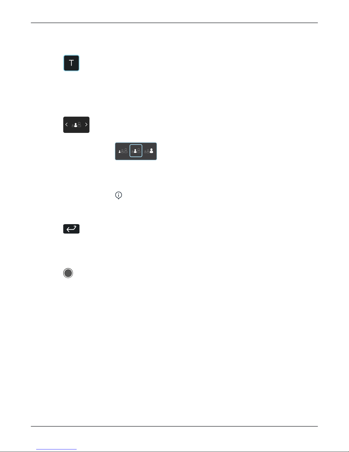
IMAGING PROGRAM SETTINGS:
Test mode
Indicates if Test mode is active.
Press Test mode icon to disable/enable device radiation production.
This mode can be used for example to demonstrate the device
movements.
You can also use the positioning panel to activate the Test mode.
Patient size
Indicates the currently selected patient size preset.
Press the Patient size selection icon to open a list of patient sizes;
Small, Medium & Large.
Press on the listed patient size icon to activate it.
Selecting a patient size, according to the scanned patient, adjusts
the kV and mA to preset levels.
NOTICE! Patient size presets can be adjusted from settings
menu.
End Study
Press End Study icon to finalize the imaging procedure and return to
the main view.
STATUS MESSAGE BAR:
Device status indicator
Status message bar shows the device status with a colored Device
status indicator.
Refer to Status indicator light for more information.
ORTHOPANTOMOGRAPH™ OP 3D 23
Page 24
4 Device description
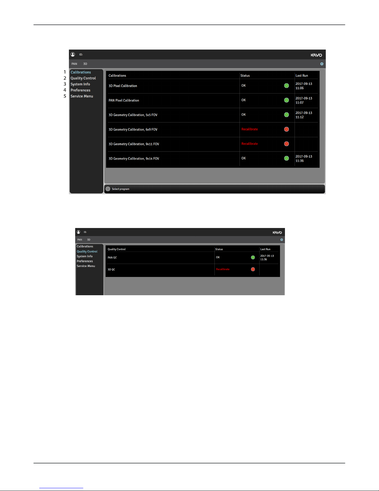
Settings menu
1. QUALITY CONTROL
Shows a list of Quality Control (QC) programs, their completion status and last
completion date.
24 ORTHOPANTOMOGRAPH™ OP 3D
Page 25
4 Device description
2. CALIBRATIONS
Shows a list of user performable device calibrations, their completion status and last
completion date. The calibrations are performed through this menu.
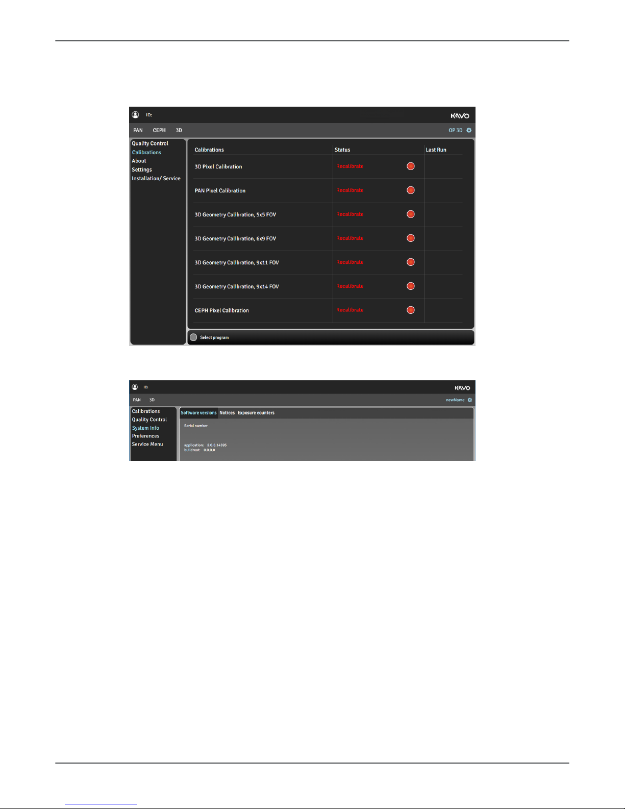
3. SYSTEM INFO
Software
versions
Show the device serial number and firmware versions.
Notices Legal information and terms and conditions for use.
Exposure
counters
Show amount of exposures taken with the device.
ORTHOPANTOMOGRAPH™ OP 3D 25
Page 26

4 Device description
4. PREFERENCES
Friendly name Set a name for the device, which is shown
next to the settings icon and on the
imaging software.
3D Metal Artefact
Reduction
Enable or disable MAR, Metal Artefact
Reduction. MAR is used to reduce
the effect of metals and other dense
radiopaque objects on the 3D image.
It is recommended to keep MAR activated.
Force device
language
Change the language of the GUI if needed.
It is recommended not to force the
language of the GUI but change the
language profile of the workstation.
Configurations
Default to Scout
before 3D
Enable or disable automatic Scout image
activation when a 3D imaging modality is
selected.
It is recommended to have the Scout
image taking enabled.
NOTICE! If the selection is set to
"disabled", a Scout image mode can
still be activated manually in the 3D
imaging program selection view.
26 ORTHOPANTOMOGRAPH™ OP 3D
Page 27

4 Device description
Patient size
configuration
Adjust the default mA and kV values for imaging programs.
5. SERVICE MENU
NOTICE! This menu is intended for authorized service personnel only.
The Service menu can be accessed only with a PIN code.
The Service menu contains:
• Device settings
• Calibrations for installation and service of the device
• Optional imaging programs activation
• Demonstration mode activation for exhibition use
• Verification programs for radiation related testing
ORTHOPANTOMOGRAPH™ OP 3D 27
Page 28
4 Device description
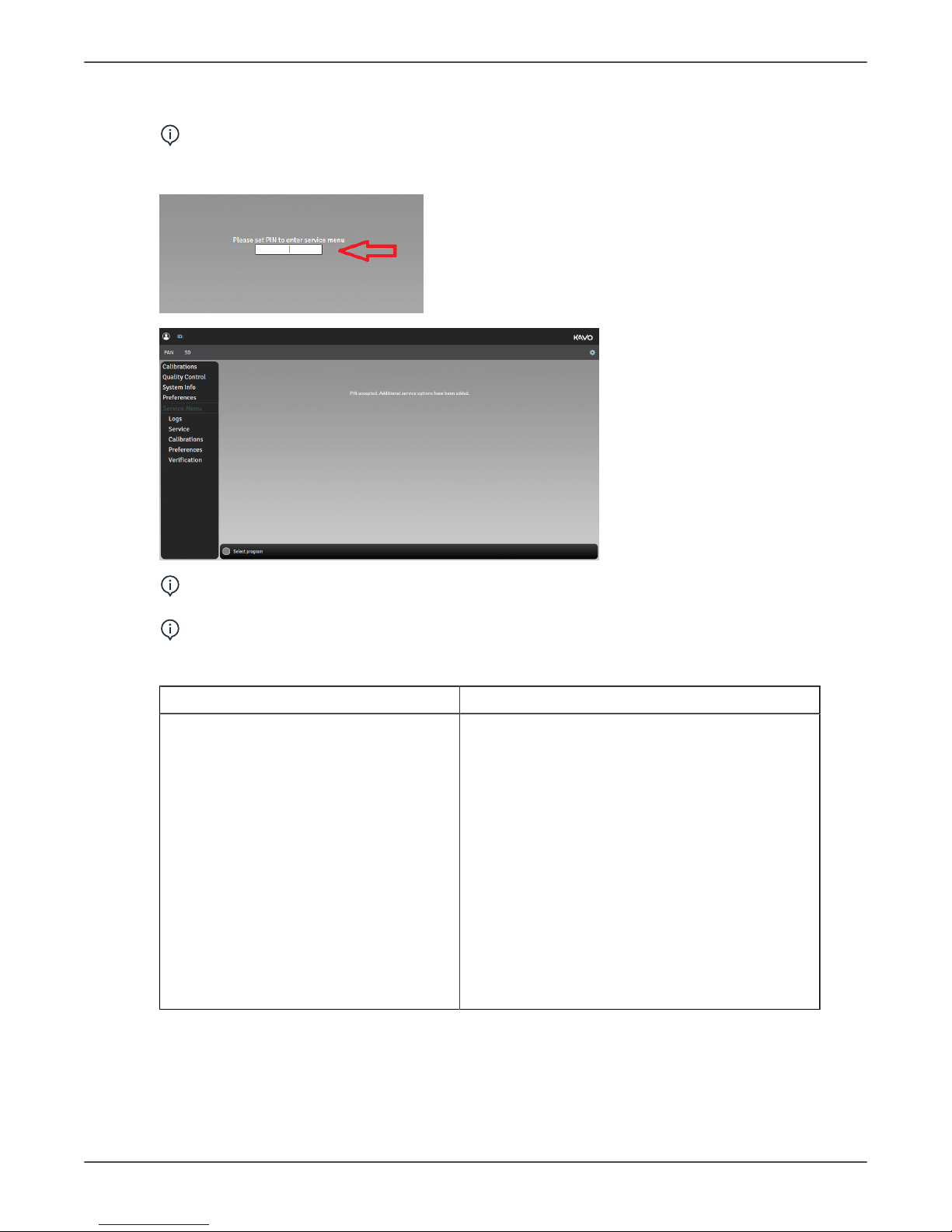
Service menu
NOTICE! The Service menu is intended only for authorized service men for
service use.
To access the Service menu from the Settings, input PIN code 1917 to the field:
NOTICE! PIN code 0612 is intended for installation only and contents of the
Service menu is limited. See the table below.
NOTICE! As a user of the OP 3D Service manual, you have a full access to the
Service menu.
In the Service menu you can:
PIN 1917 PIN 0612
• Access the device logs and errors
(Logs)
• Update the device sofware
(Service)
• Drive the device to packing position
(Service)
• Perform motion tests(Service)
• Perform device calibrations
(Calibrations)
• View and modify configuration
preferences, for example: Define
calibration intervals, enter license
keys, select country (Preferences)
• Perform PAN and 3D tests
(Verification).
• Drive the device to packing position
(Service)
• Perform device calibrations (Calibrations)
• View and modify configuration preferences,
for example: Define calibration intervals,
enter license keys, select country
(Preferences)
• View and modify patient size configurations
(Preferences)
• Demo mode (Preferences)
• Perform PAN and 3D tests (Verification)
28 ORTHOPANTOMOGRAPH™ OP 3D
Page 29
4 Device description
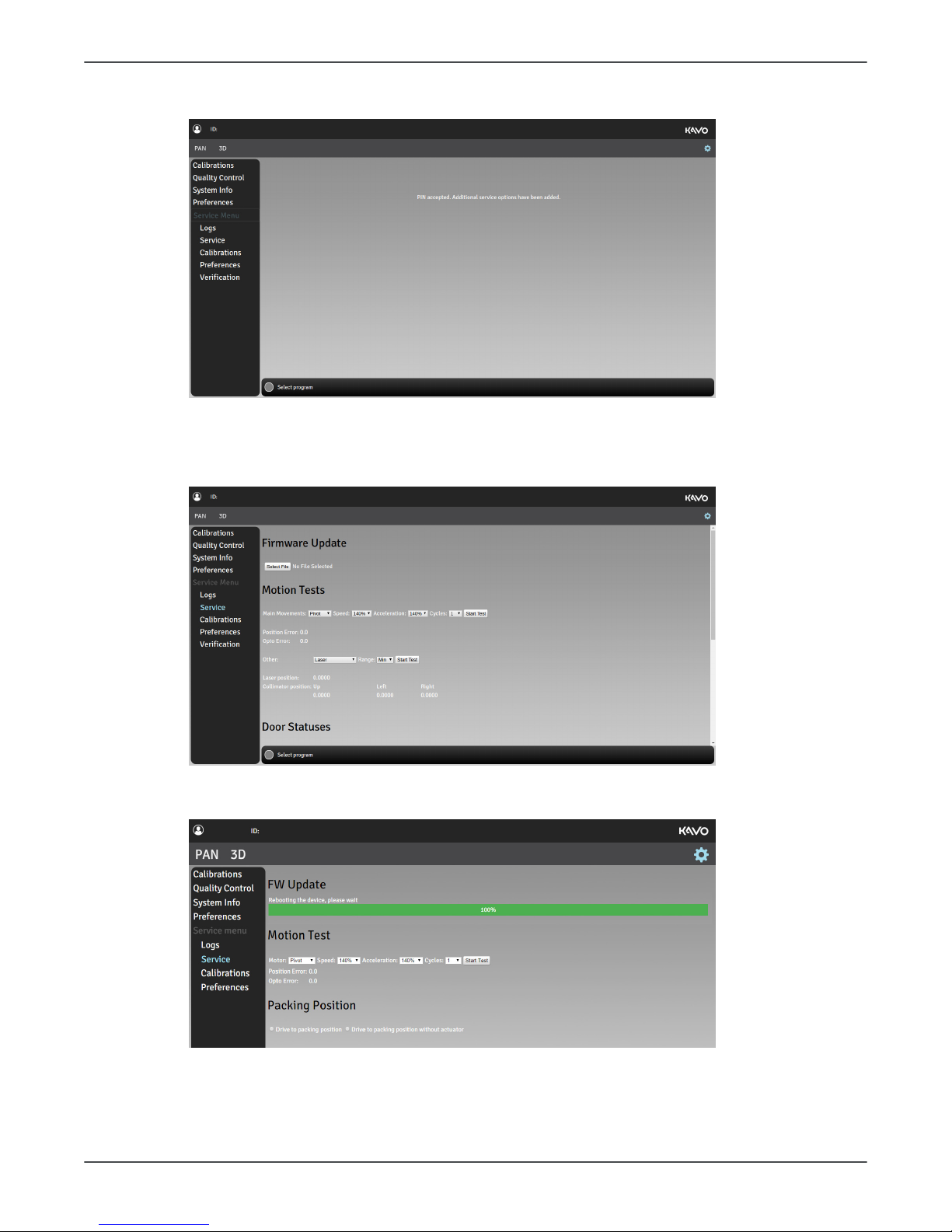
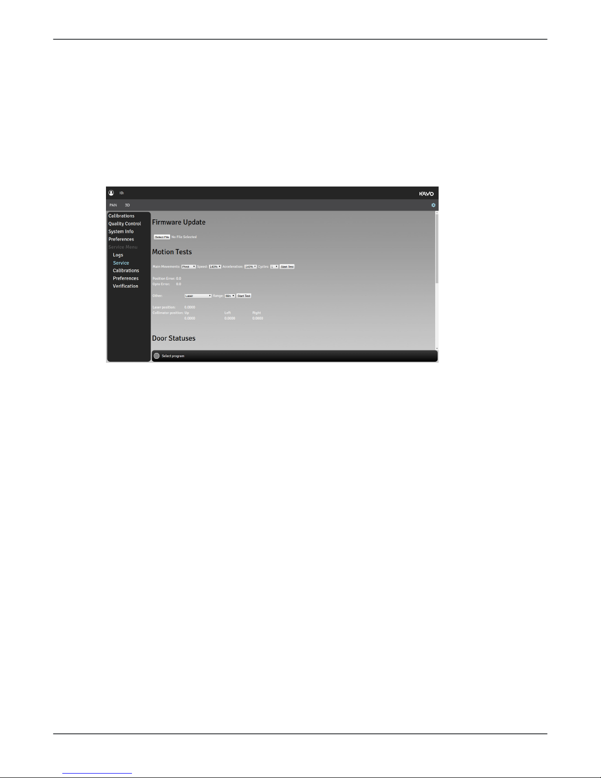
Service
In the Service menu you can:
• update the device firmware
• perform accelerated motion test for different main movents
• test the door and mirror door switch status change
• drive the device to packing position
• test the 3D sensor connectivity
• test the functionality of internal communication buses
• check the statuses of the internal power supplies.
For more information on how to update the device firmware, see chapter Firmware
update.
Motion tests are used for testing the individual movements of the device. To perform a
motion test to the following:
• Select the main movement (PIVOT, ROTATION, LINEAR) or other movement (LASER,
UPPER COLLIMATOR, LEFT COLLIMATOR, RIGHT COLLIMATOR)
• For main movements, select the number of movements for the test.
• For other movements, select the range of movement (min/max). Change the range
between tests when you test the same movement.
• Press the exposure button to perform the movement.
• Verify the selected movement visually.
Internal communication bus test results and power supply status results are provided in
the system logs. After you have executed the test, check the results from Logs menu by
clicking log/messages.
Logs
In the Logs menu you can access device logs and error messages.
To dowload logs or error messages to the workstation, select the logs/error messages
and click Download.
ORTHOPANTOMOGRAPH™ OP 3D 29
Page 30
4 Device description
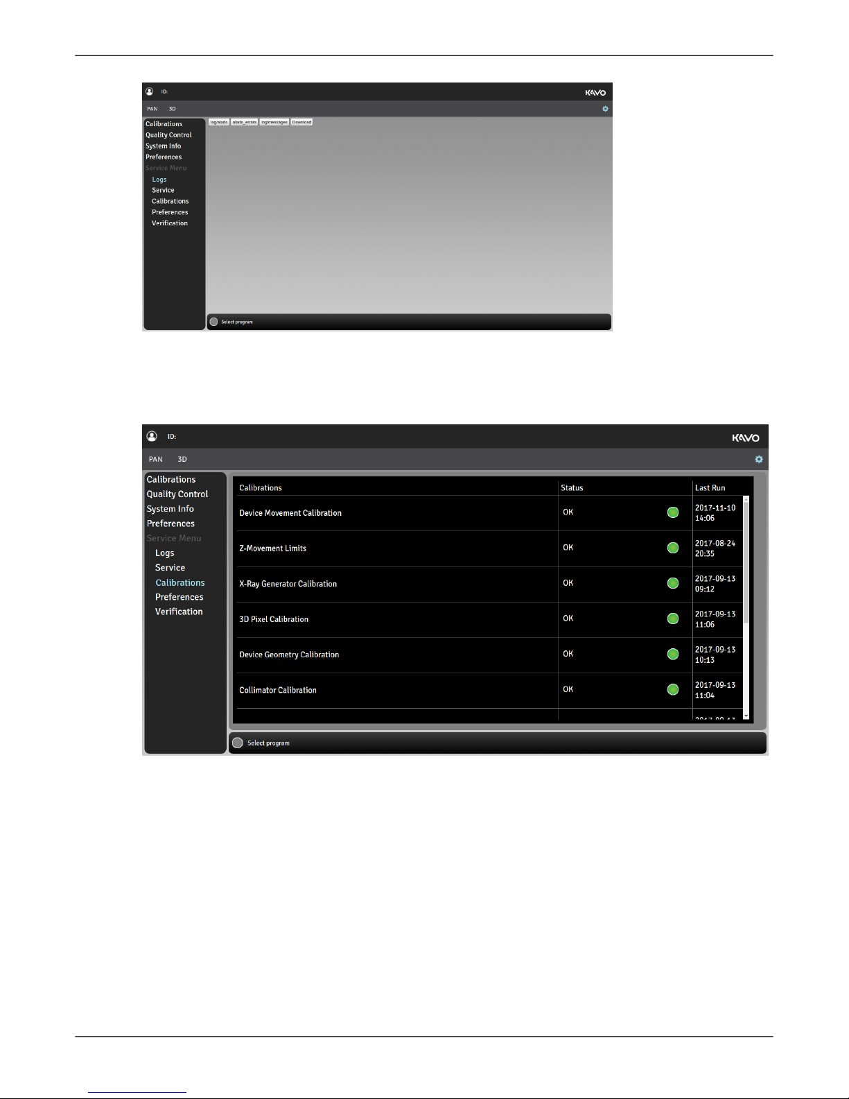
Calibrations
In the Calibrations menu you can select the device calibrations that you want to
perform.
For information on how to perform the calibrations, see User and Installation manual.
Preferences
In the Preferences> Configurations you can:
• enter a friendly name (for the device)
• select the desired intervals for User calibrations, Service calibrations, PAN QC, 3D QC
• enter licence keys
• change the device language
• enable the default Scout before 3D
• select the country
• enable the Door switch
• enable the Demo mode
• specify the DAP calibration factor.
30 ORTHOPANTOMOGRAPH™ OP 3D
Page 31

4 Device description
Refer to User and Installation manual, chapter Device configuration for instructions on
setting and using the Preferences menu items.
In the Preferences > Patient Size Configuration you can:
• adjust the medium size patient values
Verification
The device offers Panoramic and 3D verification test programs with the device
movements disabled. These programs can be used for radiation related measurements.
A separate radiation measuring device/equipment is required for taking the radiation
measurements.
1. Go to Settings menudevice settings.
2. Select Service menu and enter PIN code 1917.
3. Select Verification menu that appears under the Service menu.
4.
ORTHOPANTOMOGRAPH™ OP 3D 31
Page 32

4 Device description
5. Select the PAN testing tab for Panoramic verification test or 3D testing tab for 3D
verification test.
6. Adjust the verification test settings:
PAN testing
• Select the mA and kV values for the test program using the + and - buttons.
7. Attach the measuring device in front of the sensor cover. The detector of the
measuring device must be positioned to the area where the X-ray beam hits. The
center of this area is located approximately 2,5 cm from the left side of the detector
opening.
NOTICE! The X-ray beam must fully hit the detector of the measuring device.
NOTICE! You may use a fluorescent screen to pinpoint the beam location
more accurately.
NOTICE! When using the PAN testing program, the X-Ray beam is adjusted
wider (over 2 cm) than in normal imaging programs to allow easier positioning
of the measurement device.
8. Protect yourself from radiation.
9. Press and hold down the exposure button to start the test program.
10. When the exposure warning stops and the program end tone is played, the program
is complete.
11. Review the measurement data. The measured kV shouldn't differ more than 5kV
from the set value.
32 ORTHOPANTOMOGRAPH™ OP 3D
Page 33

4 Device description
12. If the verification fails, ensure the alignment of the measurement device and redo
the test program. If the problem persists, contact service.
13. Adjust the verification test settings:
3D testing
• Select the length of the radiation pulse, 5ms (LDT/standard), 10ms (Standard
resolution) or Constant (High/ENDO resolution).
• Select the mA value for the test program using the + and - buttons.
14. Perform the 3D testing.
4.4.2 Positioning panel
1. Carriage up/down slider. The carriage can be driven up and down by sliding a finger
on the carriage up/down slider. The speed of the carriage movement depends on the
distance the finger is moved.
2. Test mode button. Disables radiation production of the device. You can also use the
GUI to activate the Test mode.
3. Patient positioning lights button. Turns the patient positioning lights on/off.
4. HOME button. Drives the rotating unit to HOME (Patient-In) and scan start positions.
5. Exposure indicator (YELLOW). Illuminates when the device is radiating.
6. Status indicator (BLUE). Illuminates when the device is in Error state. The error
details are shown on the GUI.
7. Ready indicator (GREEN). Illuminates when the device is ready for imaging.
NOTICE! If carriage up/down slider backlight is not illuminated, the carriage up/
down slider is in safe mode and cannot be used. Wait until the light comes back on
or wipe the panel clean if it is dirty.
ORTHOPANTOMOGRAPH™ OP 3D 33
Page 34

4 Device description
4.5 Circuit boards
4.5.1 i2000 image capture board
The i2000 image capture board is located on top of the rotating unit, see Locations of
circuit boards.
The i2000 board handles image capturing function of the OP 3D X-ray imaging system.
The main functions of the i2000 board are listed below.
• Image capturing from both the 3D and the PAN sensor
• Image storing to the image memory
• Image transmission to the modality workstation.
• Driving the
• spinning of the rotation unit
• collimator plates.
• Providing voltage for the sensors.
34 ORTHOPANTOMOGRAPH™ OP 3D
Page 35

4 Device description
Table 2: Indicators
LED # Color Default
state
Function Notes
H1 Green ON Configuration done
H2 Green ON Ethernet Link
H3 Green ON FPGA init done
H4 Green Blinking Ethernet RX/TX activity
H5 Green ON P1V35 PG OFF when device is
in the sleep mode
H6 Red OFF FPGA PIO LED5
H7 Green OFF PAN_P5V_D_3D ON when 3D
imaging mode
selected and device
is reserved.
H8 Green OFF PAN_P5V_A_CEPH ON when 3D
imaging mode
selected and device
is reserved and.
H9 Green OFF Panel supply P12/P6V PG ON when the device
is reserved
H10 Green OFF PAN_P12V ON when 3D
imaging mode
selected and device
is reserved.
H11 Green ON P24V Board input voltage
H12 Red OFF FPGA FW_ERR ON when error state
H13 Red OFF FPGA CORE_ERR ON when error state
H14 Green Blinking FPGA PIO LED1
FPGA PIO LED0-2
forms a group of
running lights.
Fast blinking (1s
round time) when
FPGA boots up.
Slow blinking
(8s round time)
when FPGA fully
operational.
H15 Green ON P3V3 PG OFF when device is
in the sleep mode.
H16 Red OFF FPGA PIO LED4
H17 Green ON P5V PG OFF when device is
in the sleep mode
H18 Green Blinking FPGA PIO LED2 See H14
H19 Green OFF FPGA PIO LED3
H20 Green Blinking FPGA PIO LED0 See H14
ORTHOPANTOMOGRAPH™ OP 3D 35
Page 36

4 Device description
LED # Color Default
state
Function Notes
H21 Red OFF Motor driver POR on ON when a motor
malfunction
detected
H22 Green ON DDR_VTT OFF when device is
in the sleep mode
H23 Green Blinking MCU STAT0 MCU SW controlled
LED
H24 Green ON NSTATUS
H25 Red OFF FPGA RESET
H26 Green OFF CPAN_P12V ON when PAN
imaging mode
selected.
H27 Red OFF MCU STAT1 SW controlled LED
H28 Green ON P24V_MOTOR +24Vdc power input
for motors.
H29 Green OFF PAN_P5V_D_CEPH ON when
PANimaging mode
selected.
H30 Green OFF PAN_P5V_A_3D ON when PAN
imaging mode
selected.
36 ORTHOPANTOMOGRAPH™ OP 3D
Page 37

4 Device description
i2000 fuses
Location Ref Value Type Replaceable
i2000 F1 FUSE slow 4A
250Vac 5x20 mm
Cooper Bussmann
S506-4-R
Yes
i2000 F2 FUSE slow 6.3A
250Vac 5x20mm
Cooper Bussmann
S506-6.3-R
Yes
i2000 F3 Resettable Fuse
PPTC 16V, 0.25A,
Itrip 0.5A
Cooper Bussmann
PTS120616V025
No
Replacing the i2000 image board
To replace the board, follow the instructions given in chapter Replacing the i2000 image
capture board.
4.5.2 i3000 Main control board
The i3000 main control board is located on top of the upper shelf. See figure Locations of
circuit boards.
The i3000 board is the main controller of the OP 3D X-ray imaging system. The main
features of i3000 board are listed below.
Functionality
The main functions of the i3000 Main control board are:
• Main control of the system
• Linear and pivot motion drive and position sensing
• Exposure control
• Image data streaming between i2000 and MWS
• Audio output
• User interfaces
• Remote GUI through LAN
• I4000 and i2000 firmware & FPGA updates.
ORTHOPANTOMOGRAPH™ OP 3D 37
Page 38

4 Device description
Indicators
LED # Color Default state Function Notes
H1 Green ON VAUX33 power on
H2 Green ON MWS Ethernet link
H3 Green ON i2000 Ethernet link
H4 Green ON/blink MWS Ethernet RX/TX
activity
H5 Green OFF Motor in reset (POR)
H6 Green ON
+24V supply connected to
board and
FUSE ok
H8 Green ON/blink MPU STAT0 SW controlled LED
H9 Green ON P3V7 power on
H10 Green ON/blink i2000 Ethernet RX/TX
activity
H11 Green ON
+24V supply connected to
board and
FUSE ok
H12 Green ON Photo interrupter power on
H13 Green OFF Motor in reset (POR)
H14 Green ON/blink MCU STAT0 SW controlled LED
H15 Green ON P3V3 power on
H16 Green OFF Board main reset active
(power up)
H17 Green ON P5V power on
H18 Red OFF MPU STAT1 SW controlled LED
H19 Red OFF Peripheral reset active Control reset
H20 Green ON P1V8 power on
H21 Green ON VMMC power on
H22 Green ON DDR VTT ok
H23 Red OFF MCU STAT1 SW controlled LED
38 ORTHOPANTOMOGRAPH™ OP 3D
Page 39

4 Device description
i3000 fuses
Location Ref Value Type Replaceable
i3000 F1 6,3AT/250Vac Cooper Bussmann
S506-6.3-R
Yes
i3000 F2 4A 250Vac slow (5x20mm) Cooper
Bussmann S506-4-R
Yes
i3000 F3 1,1A/6V Resetable PTC#fuse No
i3000 F4 1,1A/6V Resetable PTC#fuse No
i3000 F5 0,25A/16V Resetable PPTC#fuse No
i3000 F6 2A/6V Resetable PTC#fuse No
i3000 F7 0,25A/16V Resetable PPTC#fuse No
i3000 F8 0,25A/16V Resetable PPTC#fuse No
Replacing the i3000 circuit board
To replace the board, follow the instructions given in chapter Replacing the i3000 main
control board.
ORTHOPANTOMOGRAPH™ OP 3D 39
Page 40

4 Device description
4.5.3 i4000 power supply board
The i4000 power supply board is located on the carriage. See figure Locations of circuit
boards.
The i4000 board is one of three control boards of the OP 3D X-ray imaging system. The
main features of the i4000 power supply board are listed below.
Functionality
• Generate all main supplies to OP 3D
• UI control
• Z motor control and position sensing
• Laser motor control and position sensing
• Chin rest sensor interface
• Patient positioning lights control
• Scan motor control and positioning
• Filament control
• HV control
Indicators
LED # Color Default state Function
H1 Green ON +3V3HV is on
H2 Green ON #15V is on
H3 Green ON +20V Triac is on
H4 Green ON +17V is on
H5 Green ON HV395 is on
H6 Green ON PFC power is on
H7 Green ON P15V is on
H8 Green OFF Preheat is on
H9 Green ON P3V3 is on
H10 Green ON P5V is on
H11 Green ON +24V is on
H12 Red OFF Tubefail error
H13 Green ON +20V DCDC
H14 Yellow OFF Exposure on
H15 Yellow OFF Power detected
LA100 ON Mains voltage on
40 ORTHOPANTOMOGRAPH™ OP 3D
Page 41

4 Device description
i4000 fuses
Location Ref Value Type Replaceable
i4000 F1 FF8A/500Vac (6,3x32mm) Siba
70-125-40 8A
Yes
i4000 F2 2A/6V
Resetable PPTC
fuse Littelfuse
0805L200SLTHYR
No
i4000 F3 8AT/250Vac (5x20mm) Cooper
Bussmann S506-8-R
Yes
i4000 F4,
F6-9
0.5A/6V Resetable PTC#
fuse Bourns MFPSMF050X
No
i4000 F5 0.25A/16V Resetable PPTC#fuse No
i4000 F10 0.5A/6V Resetable PTC#fuse No
i4000 F11,
F12
2A/250Vac (TE5) Littelfuse
39212000440
No
Replacing the i4000 circuit board
To replace the board, follow the instructions given in chapter Replacing the i4000 power
supply board.
ORTHOPANTOMOGRAPH™ OP 3D 41
Page 42

4 Device description
4.5.4 i4100 back panel board
The i4100 back panel board is located on the backside of the carriage. See Locations
of circuit boards. The board has a mains input connector and mains fuses. It also has
several connectors to external features.
The main features of the i4100 back panel board are listed below.
Functionality
• Mains fuses
• Switch of permanent or non-permanent mains installation:
• When the non-permanent installation is made, both L (live) and N (neutral) fuses
must be used. Switch SW1 must be set to 2F position.
• When the permanent installation is made, only L (live) fuse must be used. Switch
SW1 must be set to 1F position.
• Mains switch is connected to this board
• Exposure switch connector
• Remote exposure switch connector
• Door switch connector
• External warning light connector
Table 3: Indicators
LED # Color Default state Function Notes
H1 Green ON Green led
controlled by
FW.
Replacing the i4100 circuit board
To replace the board, follow the instructions given in chapter Replacing the i4100 back
panel board.
i4100 fuses
See chapter Fuses.
4.5.5 i6000 user interface board
The i6000 user interface board is located on the lower shelf. See figure Locations of
circuit boards.
The i6000 user interface board contains no parts that can be serviced. The board comes
as a part of the lower shelf assembly.
Replacing the i6000 circuit board
To replace the i6000 board you need to replace the lower shelf upper cover assembly,
see chapter Replacing the lower shelf upper cover assembly.
Test points
J3 GND test clip
4.5.6 i8000 LED indicator board
The i8000 LED indicator board is located between the carriage and the upper shelf. See
figure Locations of circuit boards.
Functionality
42 ORTHOPANTOMOGRAPH™ OP 3D
Page 43

4 Device description
The i8000 board generates exposure warning, ready and error status indications. The
status is indicated with colored LEDs.
Indicators
Refer to Status indicator light for the indicators.
Replacing the i8000 circuit board
For instructions on how to replace the i8000 LED indicator board, see chapter Replacing
the i8000 LED indicator board.
ORTHOPANTOMOGRAPH™ OP 3D 43
Page 44

4 Device description
4.5.7 i9000 chin rest sensor board
The i9000 chin rest sensor board is located in the lower shelf. See figure Locations of
circuit boards.
Functionality
The i9000 board senses the chin rest positions and calibration phantoms with three HALL
sensors.
Indicators
Replacing the i9000 board
For instructions on how to replace the i9000 chin rest sensor board, see chapter
Replacing the i9000 chin rest sensor with lasers.
Fuses
None.
Test points
None.
44 ORTHOPANTOMOGRAPH™ OP 3D
Page 45

5 Diagrams
5 Diagrams
5.1 Wiring diagram
ORTHOPANTOMOGRAPH™ OP 3D 45
Page 46

5 Diagrams
ROTATING UNITTHA
PAN3D
i7000 TUBEHEAD
INTERFACE BOARD
i2000 IMAGE
CAPTURE BOARD
J2013 J2017
J2005
J7005
J7003
J7001
J7000 J7002
SELF
DIAGNOSTICS
i5000 CASCADE BOARD
J5001J5005
J5003 J5002
TUBE
J1036
COL RIGHT
BORDER
2PH
J1035
COL LEFT
BORDER
2PH
J1034
COL UPPER
BORDER
2PH
J1031
J1032
J1033
CRB HOME
CLB HOME
CUB HOME
J2003
J1028
J1029
LIMIT 3D
LIMIT PAN/CEPH
J1014
DETECTOR
SWAP (D)
2PH
J2012
J2015
J2007
J2015
J2007
J2003 J2001J2002
J1012
ROTATING
2PH
ROT. HOME
J1027 J1013
ABS.
ANGLE
J2000 J2011 J2004J2010
J0601
J0100
J0101
J0300
J0301
J0200
J0201
J0400
J0401
J0500
J0501
SENSOR ASSEMBLY
J1107
J1106
1
2
3
4
5
6
7
46 ORTHOPANTOMOGRAPH™ OP 3D
Page 47

5 Diagrams
5.2 Fusing diagram
i4100 BACK PANEL BOARD
i4000 POWER SUPPLY i2000 IMAGE CAPTURE
i3000 MAIN CONTROL
PFC DC/DC
GENERATOR
STAND-BY
SUPPLY
SUPPLY
SWITCH
F1
F2
SW1
F12
F11
F1
F1
F2
F3
F6
Motors
Logic
Motors
Motors
Logic
L
N
MAINS INLET
5.3 Emergency stop
i4000
10
J1011
J4002
Emergency stop button
11
3
6
1
3
3
1
5.4 Mains voltage distribution
i4100 i4000
MAINS SWITCH
4 2 1 3
L
LIVE
NEUTRAL
PROTECTIVE EARTH
MAINS CORD
J4107
2
1
F1
F2
J4018
L N
N
SW1
J4106
1A 2A 2 1
J4001
2
1
ORTHOPANTOMOGRAPH™ OP 3D 47
Page 48

5 Diagrams
5.5 Power distribution +24Vdc
13
2 5
P24V
P24V_MOT
i2000
P24V_MOT ON
P24V ON
24V
P24V_MOT
P24V
P24V ON P24V MOTOR ON
24V
i4000
P24V ON
P24V P24V
J4016
J4019
i4100
i3000
F1
F2
F1
F2
24V
J4101
THA
J1005
J7000
24V
8
13
8
J4013
24V power supply
2 5
1
2
J4020
1
2
13
8
13
8
1
2
J3002
J3003
1
2
J2000
5.6 Ethernet communication
i2000 i3000
Back panel
J1002
J2011
J3007
J3006
Link
OK
Link
OK
Link
OK
LAN
or
MWS
5.7 CAN communication
2
i2000
i3000
i4000
J2010
J3009
J4009
1
2
1
2
1
2
1
48 ORTHOPANTOMOGRAPH™ OP 3D
Page 49

5 Diagrams
5.8 i2C self diagnosis communication
i2000
i3000
3
1
2
4
3
J3008
J2004
+5Vdc
i4000
4
+24Vdc
J4019
i7000
THA
PAN
+5V ON
2
1
+5Vdc
3
J3001
+5Vdc
4
2
1
3
1
2
4
J4006
+5Vdc
2 6 12 5
10
2
9
5
J7000
+5Vdc
5.9 Rotation movement
i2000
J2001
J2010
J2002
CAN BUS
FROM
i3000
J1013
J1027
ROT. ABS.
ROT. HOME
J1012
M
2ph Step
MOTOR
ERROR
ORTHOPANTOMOGRAPH™ OP 3D 49
Page 50

5 Diagrams
5.10 Linear movement
i3000
J3004
J
J3010
J3011
CAN BUS
FROM
i4000
J1017
J1025
LINEAR ABS.
LINEAR HOME
J1015
M
2ph Step
5.11 Pivot movement
i3000
J3005
J
J3010
J3011
CAN BUS
FROM
i4000
J1018
J1026
PIVOT ABS.
PIVOT HOME
J1016
M
2ph Step
50 ORTHOPANTOMOGRAPH™ OP 3D
Page 51

5 Diagrams
5.12 Z movement
UI PANEL
+
i6000
i4000
Z-ACTUATOR
CAN BUS
From i3000
E
J1037
Z-HOME
J6001
J4007
J4009
J4002
M
DC
TACOMETER
J1011
J1039
5.13 Collimator movements
ORTHOPANTOMOGRAPH™ OP 3D 51
Page 52

5 Diagrams
5.14 Positioning lights
i4000
J4018
J4009
J4010
J4003
LASER LIFT
J1022
J1008
J1009
J1003
J1010
3D FOV
HEIGHT
POSTERIOR
ANTERIOR
SHARP
LAYER
MID
SAGITTAL
LASER HOME
M
2ph Step
CAN BUS
FROM
i3000
5.15 Imaging chain 3D
1
2
4
3
1
2
3D X-ray
sensor
J601
3
4
7
8
J101
i2000
J0301
J2015
J3007
IMG.MEM
i3000
J2013
J2013
J3006
Status
J1002
Back
panel
J2013- 3:GND (trigger)
- 4: Ext.trigger
- 7: +12Vdc
- 8: GND (PWR)
H10
+12V OK
IMG.DATA
LVDS
LAN
LAN
52 ORTHOPANTOMOGRAPH™ OP 3D
Page 53

5 Diagrams
5.16 Exposure control 1
i4000
THA PAN
i7000
THA CEPH
i7000
1
J4019 J7000
J7002
J1004
J1005
J4016
J7000
J4005
J4004
J7002
2
3
4
5
8
12
9
1
2
3
4
5
7
11
8
1
2
1
2
1
2
3
4
5
7
11
8
1
2
1
2
3
4
5
7
11
8
1
2
1
2
3
4
5
7
11
8
1
2
5.17 Exposure control 2
i4100
i4000
2
P5V
P3V3
J4103
J4014
J4102
J4102
Door switch
1
2
1
2
1
8
7
Remote exposure
button
Remote exposure
button
Exposure button
J4101
2
1
6
3
8
7
2
1
6
3
8
7
J4013
ORTHOPANTOMOGRAPH™ OP 3D 53
Page 54

5 Diagrams
5.18 Exposure warning light
3
5 6
5
6
Remote controller
Exposure
warning
J4104/
J4102
1
J4105
External
warning
lamp
i4100
i4000
J4101
J4013
J4007
J6001
i6000
Exposure
warning
Error
Ready
J8000
i8000
Exposure
warning
Error
Ready
J4022
7
8
12
13
3
7
8
12
13
1
2
8
9
6
10
1
2
8
9
6
10
1
2
3
4
5
6
1
2
3
4
5
6
2
F3
5.19 Device control panel
i6000
J6001
i4000
J4007
J4009
CAN
BUS
FROM
i3000
Positioning
panel
54 ORTHOPANTOMOGRAPH™ OP 3D
Page 55

5 Diagrams
5.20 Chin rest detection
1
HAL-C
HAL-B
HAL-A
J4009
i4000
CAN
BUS
FROM
i3000
J9001
i9000
4
3
7
6
10
2
1
3
4
5
6
ORTHOPANTOMOGRAPH™ OP 3D 55
Page 56

6 Maintenance
6 Maintenance
The maintenance and calibration procedure intervals described here are minimum
requirements and can be made more frequent and stringent to comply with local
regulations regarding the use and maintenance of dental X-ray devices.
6.1 Annual maintenance
Annual maintenance procedures must be performed annually to ensure that the
performance and functionality of the device remains consistent. Annual maintenance
consists of visual inspections, functional tests and calibrations.
Carry out the following inspections during the annual maintenance:
• Check that all fixing screws are tight.
• Check that all covers and mechanical parts are correctly secured and have not come
loose.
• Check that the protective earth is connected.
• Check that no oil is leaking from the tube head.
Perform the following maintenance procedures:
• Confirm the cleanliness of the device. See chapter Cleanliness of the device.
• Check the condition of external cables. See chapter Condition of the cables.
• Check device movements and common device functionality. See chapter Device
movements and functionality.
• Check that the exposure warning indicators work correctly. See chapter Exposure
indicator functionality.
• Perform all calibrations and QC programs described in the User and Installation
Manual.
NOTICE! Compare the QC program results to the previous reference images
and if no noticeable image quality degradation is apparent, save the images as
new reference images and inform the user of their location.
6.1.1 Cleanliness of the device
The device has to be cleaned regularly as instructed in the User and Installation Manual.
NOTICE! Switch the device off before cleaning it.
Use a soft cloth dampened with a mild detergent to clean the:
• Device covers and outer surfaces in general
• Patient positioning mirror
• Positioning panel
Check, that any vents in the covers are not blocked with dust and that no dust has
accumulated inside the device. Clean the vents and remove the covers to remove the
dust inside the device if necessary.
6.1.2 Condition of the cables
1. Visually check that the power supply cord is in good condition and not damaged in
any way.
2. Visually check that the exposure button cable is in good condition and not damaged
in any way.
56 ORTHOPANTOMOGRAPH™ OP 3D
Page 57

6 Maintenance
3. Visually check that the Ethernet cable is in good condition and not damaged in any
way.
4. Visually check that the Remote exposure switch cable, Remote warning light cable
and door switch cable, if installed, are in good condition and not damaged in any
way.
5. Check that all of the cable connectors are properly attached and are routed through
the strain relief.
6. Replace the damaged cables if necessary.
6.1.3 Device movements and functionality
1. Power the device on from the power switch.
2. Power the workstation on and launch the imaging software to access the device GUI.
3. Select 3D modality and the largest FOV size available.
4. Set the device into Test mode.
5. Press and hold the exposure switch down.
6. Check the smoothness of the rotation and pivot movements. Monitor the device
operation and observe for any excessive noises or evident vibrations of the device
during its rotation and pivot movements. Also make sure that the rotation and pivot
movements are continuous until the end of exposure.
NOTICE! If the exposure switch is released, the device movements should
stop.
7. Press the HOME button to drive the device back to Home position.
8. Monitor the device operation and observe for any excessive noises or evident
vibrations of the device during its rotation movement.
9. Drive the device Up/Down using the positioning panel.
10. Monitor the device during up and down movement and observe for any excessive
noises or non-smoothness of the movement.
NOTICE! Check that the upward movement stops at the set Z-movement
limit.
ORTHOPANTOMOGRAPH™ OP 3D 57
Page 58

6 Maintenance
11. Select Pan and 3D imaging modalities from the device GUI and press the Patient
positioning lights button. Check that the correct lights are lit according to the
selected modality. For more information on the positioning lights, see the User and
Installation Manual.
12. Press the emergency stop switch.
13. Check that the device GUI indicates that the emergency stop switch has been
pressed.
NOTICE! The device restarts after the emergency stop has been pressed.
14. Make sure that the device cannot be driven up/down, rotated by pressing the HOME
button and that an exposure cannot be taken while the emergency stop switch is
activated.
15. Release the emergency stop switch by rotating it clockwise.
16. Check that the GUI indication disappears and that the movements work normally
again.
17. Switch the device off from the power switch.
18. Check that the device and all of its parts are isolated from mains and all device
functions are disabled.
6.1.4 Exposure indicator functionality
NOTICE! This check can be also done while performing the QC programs.
1. Power the device on.
2. Power the workstation on and launch the imaging software to access the device GUI.
3. Open or create a patient on the imaging software for the annual maintenance.
4. Prepare the device for Panoramic imaging and disable the Test mode.
NOTICE! Select the lowest imaging parameters available.
5. Protect yourself from radiation.
6. Press and hold the exposure button down.
58 ORTHOPANTOMOGRAPH™ OP 3D
Page 59

6 Maintenance
7. When the exposure starts, check that all exposure warning indicators are working:
• Exposure warning indicator on the GUI
• Yellow exposure indicator light on the Positioning panel
• Yellow exposure indicator light on the Status indicator light on top of the carriage.
• Audible exposure warning signal
• Remote exposure switch (if in use)
• Warning light (if in use)
8. When the exposure ends, check that the indicator lights go out, exposure warning
signal stops and a program end tone is played.
9. Check that the taken image transfers to the imaging workstation.
6.1.5 Changing the fuses
Main fuses are located at the rear of the carriage, under the back panel cover. To reach
the fuses, remove the cover first.
NOTICE! See chapter Fuses for details on the correct fuses.
To release a fuse cap, push it inwards and rotate counterclockwise with a flat head
screwdriver.
Remove the fuse from the socket and replace it with a new one. Install the fuse by
pushing the fuse cap in and rotating it clockwise with a screwdriver.
The 10A and 15A fuses are physically of different sizes and have their own fuse caps. If
you need to change the fuse rating, also the fuse cap needs to be changed. The fuses
are supplied with the corresponding fuse caps.
6.1.6 Monitor calibration
It is recommended to calibrate or check a test image with the primarily used workstation
monitor. Refer to the monitor/software manuals for information on how to do this.
ORTHOPANTOMOGRAPH™ OP 3D 59
Page 60

6 Maintenance
If you are using the Display Calibration Kit purchaceable from PaloDEx Group Oy, refer to
the Display Calibration Kit Instructions.
6.2 Calibrations
6.2.1 When to calibrate the device
The device must be calibrated and, if necessary, adjusted at regular intervals in
accordance with the national regulations regarding the use, maintenance and service of
dental X-ray devices.
The device must be re-calibrated completely at least once a year, by a service
technician according to ORTHOPANTOMOGRAPH™ OP 3D User and Installation manual.
The last calibration date for each program is listed in the calibration menu.
The device must be calibrated after the first installation or when parts are replaced:
QC images have to be taken always after calibration.
NOTICE! Refer to the OP 3D User and installation manual for the complete
calibration instructions.
60 ORTHOPANTOMOGRAPH™ OP 3D
Page 61

6 Maintenance
Table 4: Calibration matrix
i2000i3000 i4000 i3000
SD
card
CollimatorTube
head3DPanel
Pivot
and
linear
sensors
Lasers Any
part
in the
imaging
chain
Device
Movement
Calibration
X X X X
ZMovement
Limits
X X
X-ray
generator
Calibration
X X
3D Pixel
Calibration
X X X X
Device
Geometry
Calibration
X X X X
Collimator
Calibration
X X X X
PAN Pixel
Calibration
X X X X
3D
Geometry
Calibration,
5x5 FOV
X X X X
3D
Geometry
Calibration,
6x11 and
9x11 FOV
X X X X
3D
Geometry
Calibration,
9x14 FOV
X X X X
Pan QC X X X X X X X X X
3D QC X X X X X X X X X
Lasers
alignment
X
ORTHOPANTOMOGRAPH™ OP 3D 61
Page 62

7 Troubleshooting
7 Troubleshooting
Problem Possible cause Solution
Taken image is not
transferred to the modality
workstation.
Local network connection
is disrupted, which causes
loss of data.
The device stores the latest
image until a confirmation
of a succesfull transfer to
the workstation has been
received. Re-establish the
local network connection
and the image data is
transferred automatically.
Do not power the device off
or the image will be erased.
Device cannot be driven
upwards or downwards.
1. Up/down slider is on
safe mode.
2. Mechanical safety
device on the driving
motor has activated.
3. Positioning panel not
working.
1. Clean the positioning
panel and wait for the
safe mode to clear out.
2. Contact service.
No connection to the device.
1. The device is not
powered on.
2. Problem with the local
area network (LAN).
3. Check the device
configuration.
1. Power the device on.
2. Check the Ethernet
cable connections on
the workstation and the
device.
3. Restart the device and
the workstation.
7.1 Initial actions
7.1.1 Error codes
When an error code appears on the display the device will stop working and cannot be
operated while the error code is on the display.
7.1.2 Acknowledging errors
The device responds to error situations by reporting an error. Most errors may be
acknowledged using the touch screen display (by closing the dialog box the error is
reported in). Some errors require the unit to be rebooted.
If an error that requires rebooting occurs or the device fails to operate as described in
the User manual:
1. Switch off the power.
2. Wait for a few seconds.
3. Switch the power back on.
7.1.3 Image transfer
If an image is not transferred successfully to the workstation, close and then reopen the
dental imaging software and/or restart the workstation. DO NOT restart the unit as this
62 ORTHOPANTOMOGRAPH™ OP 3D
Page 63

7 Troubleshooting
will erase any image that is stored in the unit memory and this retrievable image will be
lost.
7.2 List of error codes
How to read the error codes table:
• Have the OP 3D wiring diagram available and refer to it.
NOTICE! Follow the troubleshooting procedures in the List of error codes. After
you have replaced one circuit board, switch the power back on and check if the
error has been solved. If not, proceed with the troubleshooting.
ORTHOPANTOMOGRAPH™ OP 3D 63
Page 64

7 Troubleshooting
Error code Problem Solution
E00002 Invalid error code, you should
not receive this.
Software error. Take logs and boot the
device.
E08402 Emergency button active
1. Check that emergency button is
not pressed.
2. Check connections: J4002, J1011,
Emergency button
If fail => replace emergency stop
switch with cable/column cable
extension
3. Replace i4000 board.
E08403 Exposure button active on boot
1. Release the button.
2. Check connections (no short
circuits):
* Exposure switch, J4103
* J4101, J4013
If fail => Replace exposure switch or
back panel cable
3. Replace i4100 board
4. Replace i4000 board.
E08404 Remote exposure button active
on boot
1. Release the button.
2. Check connections (no short
circuits).
* Remote exposure switch, J4104
* J4101, J4013
If fail => Replace remote exposure
switch, exposure cabling, or back
panel cable.
3. Replace i4100 board
4. Replace i4000 board.
E09002 Z motor overcurrent
1. Check that there are no obstacles
for lifting.
2. Check that no extra weight is
loaded.
3. Replace the column.
4. Replace i4000.
E09003 Z motor short circuit
1. Check cabling (that there is no
short circuit between wires or to
mechanics).
* J1037, J4002
If fail => replace column cable
extension
2. Unplug J1037, drive lift motion
64 ORTHOPANTOMOGRAPH™ OP 3D
Page 65

7 Troubleshooting
Error code Problem Solution
If same fail occurs => replace i4000
3. Replace the column.
E09004 Fan failing
1. Check that there are no obstacles/
dirt in the fan.
If fail => remove obstacles/dirt
2. Check connections:
* J4023, FAN
If fail => replace the fan
3. Check that the fan is spinning.
If fail => replace the fan
If fail => replace i4000.
E09005 Pan tubehead temperature
invalid
1. Check connections:
* J4019, J1005, J7000 (pan-THA)
If fail => replace main cable and
twister cable assembly
2. Check temperature value shown by
device
- Temperature near 0 C°
=>
* Replace main cable and E3 twister
cable assembly
* Replace THA
* Replace i4000
- Temperature near 100 C° or above
=>
* Replace THA
* Replace i4000.
E09006 Laser opto missing
1. Check connections:
* J4018, J1022
If fail => replace cable laser motor
cable
2. Replace opto fork
3. Replace i4000.
E09007 Jaw sensor missing
1. Check connections:
* J4003, J9001
If fail (open) => replace lower shelf
cable
2. Replace i9000
3. Replace i4000.
ORTHOPANTOMOGRAPH™ OP 3D 65
Page 66

7 Troubleshooting
Error code Problem Solution
E09008 UI panel missing
1. Check connections:
* J4007, J6001
If fail (open) => replace user
interface cable
2. Replace i6000
3. Replace i4000.
E09009 Z motor opto missing
1. Check connections:
* J4002, J1011, J1039
If fail (open) => replace emergency
stop with cable
* J1011, J1039
If fail (open) => replace column cable
extension
2. Replace opto fork
3. Replace i4000.
E09010 Back panel board missing
1. Check connections:
* J4013, J4101
If fail (open) => replace back panel
cable
2. Replace i4100
3. Replace i4000.
E09011 Pivot opto missing
1. Check connections:
* J3005, J1026
If fail (open) => replace pivot sensor
movement cable
2. Replace opto fork
3. Replace i3000.
E09012 Linear opto missing
1. Check connections:
* J3004, J1025
If fail (open) => replace linear sensor
cable
2. Replace opto fork
3. Replace i3000.
E09013 Rotator opto missing
1. Check connections:
* J2001, J1027
If fail (open) => replace linear sensor
cable
2. Replace opto fork
3. Replace i2000.
66 ORTHOPANTOMOGRAPH™ OP 3D
Page 67

7 Troubleshooting
Error code Problem Solution
E09014 Coll up opto missing
1. Check connections:
* J2005, J1034
If fail (open) => replace collimator
motors optos cable
* J1034, J1031
If fail (open) => replace collimator
2. Replace i2000.
E09015 Coll right opto missing
1. Check connections:
* J2005, J1036
If fail (open) => replace collimator
motors optos cable
* J1036, J1033
If fail (open) => replace collimator
2. Replace i2000.
E09016 Coll left opto missing
1. Check connections:
* J2005, J1035
If fail (open) => replace collimator
motors optos cable
* J1035, J1032
If fail (open) => replace collimator
2. Replace i2000.
E09017 Resistive sensor pivot missing
1. Check that the wiper is pressing
mechanically onto the surface of an
resistive position sensor.
If fail => replace wiper, spring and
body
2. Check connections:
* J3005, J1018
If fail (open) => replace pivot sensor
movement cable
3. Replace the resistive position
sensor
4. Replace i3000.
E09018 Resistive sensor linear missing
1. Check that the wiper is pressing
mechanically onto the surface of an
resistive position sensor.
If fail => replace linear wiper
assembly
2. Check connections:
* J3004, J1017
ORTHOPANTOMOGRAPH™ OP 3D 67
Page 68

7 Troubleshooting
Error code Problem Solution
If fail (open) => replace linear sensor
cable
3. Replace the resistive position
sensor
4. Replace i3000.
E09019 Resistive sensor rotator missing
1. Check that the wiper is pressing
mechanically onto the surface of an
resistive angle sensor.
If fail => replace wiper and spring
• Check connections:
2. Check connections:
* J2001, J1013
If fail (open) => replace rotating
sensor cable
3. Replace the resistive angle sensor
4. Replace i2000.
E09020 Stepper thermal warning
Let the device cool down.
E09021 Stepper thermal shutdown
1.1 For pivot, linear:
Replace i3000
1.2 For rotation, sensor swap:
Replace i2000
1.3 For scan motions:
Replace i4000
2.1 For collimator:
- Replace collimator
- Replace i2000
2.2 For laser lift motion:
- Replace horizontal 3D laser
assembly
- Replace i4000.
E09022 Stepper open coil
1 For pivot, linear:
1.1 Check connections:
* J3011, J1015, J1016
If fail (open) => replace linear and
pivot high torque cable
1.2 Replace motor
1.3 Replace i3000
2 For rotation:
2.1 Check connections:
68 ORTHOPANTOMOGRAPH™ OP 3D
Page 69

7 Troubleshooting
Error code Problem Solution
* J2002, J1012
If fail (open) => replace rotating high
torq mot cable
2.2 Replace motor
2.3 Replace i2000
3 For sensor swap:
3.1 Check connections:
* J2003, J1014
If fail (open) => Replace detector
swap cable
3.2 Replace motor
3.3 Replace i2000
4 For collimator:
4.1 Check connections:
* J2005, J1034, J1035, J1036
If fail (open) => replace collimator
motors optos cable
4.2 Replace collimator
4.3 Replace i2000
5 For laser lift motion:
5.1 Replace horizontal 3D laser
assembly
5.2 Replace i4000.
E09023 Mirror opto missing
1. Check connections:
* J4025, J1023
If fail (open) => replace mirror opto
cable
2. Replace opto fork
3. Replace i4000.
E09024 24V power supply voltage out of
range
Replace i4000.
E09025 24V motor voltage out of range
1.i2000:
1.1 Check fuse F2
If the fuse is blown replace the fuse.
If the fuse blows again => replace
i2000.
1.2 Replace i2000
2. i3000:
2.1. Check fuse F1
If the fuse is blown replace the fuse.
ORTHOPANTOMOGRAPH™ OP 3D 69
Page 70

7 Troubleshooting
Error code Problem Solution
If the fuse blows again => replace
i3000.
2.2 Replace i3000
E09026
Sensor current too high 1. Remove power supply connection
J2013 from i2000
1.1 Check H9 and H10 LED on i2000
board during preparation (should be
green)
If fail then
=> Replace i2000
2. Check connection: J2013, J0101
If fail then
=> Replace PAN- 3D power cable
3. Replace sensor
E10002 Invalid state shift
1.i2000:
1.1 Check fuse F2. If fuse is blown
then replace the fuse.
If the fuse blows again => replace
i2000
1.2 Replace i2000
E10003 Preheat feedback out of range
1. Re-run THA calibrations
2. Check connections: J4019, J1005,
J7000 (pan-THA)
3. Re-run THA calibrations
4. Replace i4000
5. Re-run THA calibrations
6. Replace pan-THA
7. Re-run THA calibrations
8. Replace main cable and twister
cable assembly
9. Re-run THA calibrations.
E10004 Invalid boost time
Software error. Take logs and boot the
device.
E10005 Invalid kV value
Software error. Take logs and boot the
device.
E10006 Invalid MA value
Software error. Take logs and boot the
device.
E10007 Invalid ma kV value on prepare
Software error. Take logs and boot the
device.
E10202 mA feedback out of range
1. Re-run THA calibrations
70 ORTHOPANTOMOGRAPH™ OP 3D
Page 71

7 Troubleshooting
Error code Problem Solution
2. Check connections: J4019, J1005,
J7000 (pan-THA)
3. Re-run THA calibrations
4. Replace i4000
5. Re-run THA calibrations
6. Replace pan THA
7. Re-run THA calibrations
8. Replace main cable and twister
cable assembly
9. Re-run THA calibrations.
E10203 kV feedback out of range
1. Re-run THA calibrations
2. Check connections: J4005, J4019,
J1004, J1005, J7000 and J 7002 (pan
THA)
3. Re-run THA calibrations
4. Replace i4000
5. Re-run THA calibrations
6. Replace pan-THA
7. Re-run THA calibrations
8. Replace main cable and twister
cable assembly
9. Re-run THA calibrations.
E10204 Tube fail
1. Re-run THA calibrations
2. Check connections: J4005, J4019,
J1004, J1005, J7000 and J7002 (pan
THA)
3. Re-run THA calibrations
4. Replace i4000
5. Re-run THA calibrations
6. Replace pan THA
7. Re-run THA calibrations
8. Replace main cable and twister
cable assembly
9. Re-run THA calibrations.
E10205 Calibration feedback not
increasing
1. Check connections: J4005, J4019,
J1004, J1005, J7000 and J 7002 (pan
THA)
2. Re-run THA calibrations
3. Replace i4000
4. Re-run THA calibrations
5. Replace pan THA
ORTHOPANTOMOGRAPH™ OP 3D 71
Page 72

7 Troubleshooting
Error code Problem Solution
6. Re-run THA calibrations
7. Replace main cable and twister
cable assembly
8. Re-run THA calibrations.
E10206 Calibration feedback constant
1. Check connections: J4005, J4019,
J1004, J1005, J7000 and J7002 (pan
THA)
2. Re-run THA calibrations
3. Replace i4000
4. Re-run THA calibrations
5. Replace pan THA
6. Re-run THA calibrations
7. Replace main cable and twister
cable assembly
8. Re-run THA calibrations.
E10207 Calibration feedback not raising
enough
1. Check connections: J4005, J4019,
J1004, J1005, J7000 and J 7002 (pan
THA)
2. Re-run THA calibrations
3. Replace i4000
4. Re-run THA calibrations
5. Replace pan THA
6. Re-run THA calibrations
7. Replace main cable and twister
cable assembly
8. Re-run THA calibrations.
E10208 Calibration invalid pwm
Software error. Take logs and boot the
device.
E10209 Calibration feedback invalid on
scan
1. Check connections: J4005, J4019,
J1004, J1005, J7000 and J7002 (pan
THA)
2. Re-run THA calibrations
3. Replace i4000
4. Re-run THA calibrations
5. Replace pan THA
6. Re-run THA calibrations
7. Replace main cable and twister
cable assembly
8. Re-run THA calibrations.
72 ORTHOPANTOMOGRAPH™ OP 3D
Page 73

7 Troubleshooting
Error code Problem Solution
E10210 Calibration feedback flat on scan
1. Check connections: J4005, J4019,
J1004, J1005, J7000 and J7002 (pan
THA)
2. Re-run THA calibrations
3. Replace i4000
4. Re-run THA calibrations
5. Replace pan THA
6. Re-run THA calibrations
7. Replace main cable and twister
cable assembly
8. Re-run THA calibrations.
E10211 Program unexpected event
Software error. Take logs and boot the
device.
E10402 Tube fail recovering
Software error. Take logs and boot the
device.
E10403 Calibration Unexpected event
Software error. Take logs and boot the
device.
E11002 Timeout on ack
1. Re-program i2000 board
2. Replace i2000 board.
E11003 Invalid panel mode
Software error. Take logs and boot the
device.
E11004 Unknown event
Software error. Take logs and boot the
device.
E11005 Unknown reply
Software error. Take logs and boot the
device.
E11006 Receive buffer full
Software error. Take logs and boot the
device.
E11202 Too short reply
Software error. Take logs and boot the
device.
E11203 CRC check failed
Software error. Take logs and boot the
device.
E11204 Invalid token count
Software error. Take logs and boot the
device.
E11205 Invalid cropping settings
Software error. Take logs and boot the
device.
E11206 Capturix Failed
Software error. Take logs and boot the
device.
ORTHOPANTOMOGRAPH™ OP 3D 73
Page 74

7 Troubleshooting
Error code Problem Solution
E12402 Process queue full
Software error. Take logs and boot the
device.
E12403 Parity error on wire
Software error. Take logs and boot the
device.
E12404 Overrun error
Software error. Take logs and boot the
device.
E13002 Error passive
Error source i3000:
1. Check connections:
* J3009, J2010
If fail => replace main cable
2. Replace i2000
3. Replace i3000
Error source, i2000 or i3000:
1. Check connections:
* J4009, J3010
If fail => replace twister cable
assembly
* J3009, J2010
If fail => replace main cable
2. Replace i3000
3. Replace i2000
4. Replace i4000
Error source, i4000:
1. Check connections:
* J4009, J3010
If fail => replace twister cable
assembly
2. Replace i4000
3. Replace i3000.
E13003 Error warning
Error source i3000:
1. Check connections:
* J3009, J2010
If fail => replace main cable
2. Replace i2000
3. Replace i3000
Error source, i2000 or i3000:
1. Check connections:
* J4009, J3010
74 ORTHOPANTOMOGRAPH™ OP 3D
Page 75

7 Troubleshooting
Error code Problem Solution
If fail => replace twister cable
assembly
* J3009, J2010
If fail => replace main cable
2. Replace i3000
3. Replace i2000
4. Replace i4000
Error source, i4000:
1. Check connections:
* J4009, J3010
If fail => replace twister cable
assembly
2. Replace i4000
3. Replace i3000.
E13004 Bus-off
Error source i3000:
1. Check connections:
* J3009, J2010
If fail => replace main cable
2. Replace i2000
3. Replace i3000
Error source, i2000 or i3000:
1. Check connections:
* J4009, J3010
If fail => replace twister cable
assembly
* J3009, J2010
If fail => replace main cable
2. Replace i3000
3. Replace i2000
4. Replace i4000
Error source, i4000:
1. Check connections:
* J4009, J3010
If fail => replace twister cable
assembly
2. Replace i4000
3. Replace i3000.
E13005 Stuff error
Error source i3000:
1. Check connections:
ORTHOPANTOMOGRAPH™ OP 3D 75
Page 76

7 Troubleshooting
Error code Problem Solution
* J3009, J2010
If fail => replace main cable
2. Replace i2000
3. Replace i3000
Error source, i2000 or i3000:
1. Check connections:
* J4009, J3010
If fail => replace twister cable
assembly
* J3009, J2010
If fail => replace main cable
2. Replace i3000
3. Replace i2000
4. Replace i4000
Error source, i4000:
1. Check connections:
* J4009, J3010
If fail => replace twister cable
assembly
2. Replace i4000
3. Replace i3000.
E13006 Form error
Error source i3000:
1. Check connections:
* J3009, J2010
If fail => replace main cable
2. Replace i2000
3. Replace i3000
Error source, i2000 or i3000:
1. Check connections:
* J4009, J3010
If fail => replace twister cable
assembly
* J3009, J2010
If fail => replace main cable
2. Replace i3000
3. Replace i2000
4. Replace i4000
Error source, i4000:
1. Check connections:
* J4009, J3010
76 ORTHOPANTOMOGRAPH™ OP 3D
Page 77

7 Troubleshooting
Error code Problem Solution
If fail => replace twister cable
assembly
2. Replace i4000
3. Replace i3000.
E13007 Ack error
Error source i3000:
1. Check connections:
* J3009, J2010
If fail => replace main cable
2. Replace i2000
3. Replace i3000
Error source, i2000 or i3000:
1. Check connections:
* J4009, J3010
If fail => replace twister cable
assembly
* J3009, J2010
If fail => replace main cable
2. Replace i3000
3. Replace i2000
4. Replace i4000
Error source, i4000:
1. Check connections:
* J4009, J3010
If fail => replace twister cable
assembly
2. Replace i4000
3. Replace i3000.
E13008 Bit recessive
Error source i3000:
1. Check connections:
* J3009, J2010
If fail => replace main cable
2. Replace i2000
3. Replace i3000
Error source, i2000 or i3000:
1. Check connections:
* J4009, J3010
If fail => replace twister cable
assembly
* J3009, J2010
ORTHOPANTOMOGRAPH™ OP 3D 77
Page 78

7 Troubleshooting
Error code Problem Solution
If fail => replace main cable
2. Replace i3000
3. Replace i2000
4. Replace i4000
Error source, i4000:
1. Check connections:
* J4009, J3010
If fail => replace twister cable
assembly
2. Replace i4000
3. Replace i3000.
E13009 LEC dominant
Error source i3000:
1. Check connections:
* J3009, J2010
If fail => replace main cable
2. Replace i2000
3. Replace i3000
Error source, i2000 or i3000:
1. Check connections:
* J4009, J3010
If fail => replace twister cable
assembly
* J3009, J2010
If fail => replace main cable
2. Replace i3000
3. Replace i2000
4. Replace i4000
Error source, i4000:
1. Check connections:
* J4009, J3010
If fail => replace twister cable
assembly
2. Replace i4000
3. Replace i3000.
E13010 LEC transfer error
Error source i3000:
1. Check connections:
* J3009, J2010
If fail => replace main cable
2. Replace i2000
78 ORTHOPANTOMOGRAPH™ OP 3D
Page 79

7 Troubleshooting
Error code Problem Solution
3. Replace i3000
Error source, i2000 or i3000:
1. Check connections:
* J4009, J3010
If fail => replace twister cable
assembly
* J3009, J2010
If fail => replace main cable
2. Replace i3000
3. Replace i2000
4. Replace i4000
Error source, i4000:
1. Check connections:
* J4009, J3010
If fail => replace twister cable
assembly
2. Replace i4000
3. Replace i3000.
E13011 FIFO0 overrun
Software error. Take logs and boot the
device.
E13012 FIFO1 overrun
Software error. Take logs and boot the
device.
E13013 Unkown status
Software error. Take logs and boot the
device.
E14002 Handle locked
Software error. Take logs and boot the
device.
E14003 Diag listener failed
Software error. Take logs and boot the
device.
E14402 HAL error callback
Software error. Take logs and boot the
device.
E14403 Operation read failed
Software error. Take logs and boot the
device.
E14404 Operation write failed
Software error. Take logs and boot the
device.
E15002 Flash read failed
Software error. Take logs and boot the
device.
E15003 Flash data verify failed
Software error. Take logs and boot the
device.
ORTHOPANTOMOGRAPH™ OP 3D 79
Page 80

7 Troubleshooting
Error code Problem Solution
E18202 Wrong state
Software error. Take logs and boot the
device.
E18204 Drive aborted timeout
Software error. Take logs and boot the
device.
E18205 Opto not found
1. Check connections:
* J4002, J1011, J1039
If fail (open) => replace emergency
stop with cable
* J1011, J1039
If fail (open) => replace cable column
cable extension
2. Replace opto fork
3. Replace i4000.
E18206 No pulses
1. Check connections:
* J1037, J4002
If fail => Replace column cable
extension
2. Replace i4000
3. Replace column.
E18402 Overheat
Let the device cool down.
E18404 Proximity disabled or no pulses
Software error. Take logs and boot the
device.
E18405 Drive aborted button
Software error. Take logs and boot the
device.
E19002 Self-calibration failed
1. Check that there are no objects on
the UI panel.
If fail => remove object
2. Replace the upper cover of the
lower shelf (contains the UI panel
module).
E19003 Invalid state shift
Software error. Take logs and boot the
device.
E19004 Self-diagnostic failed
1. Check connections:
* J4007, J6001
If fail => replace user interface cable
2. Replace the upper cover of the
lower shelf (contains the UI panel
module)
3. Replace i4000.
80 ORTHOPANTOMOGRAPH™ OP 3D
Page 81

7 Troubleshooting
Error code Problem Solution
E19005 Bus failing
1. Check connections:
* J4007, J6001
If fail => replace user interface cable
2. Replace the upper cover of the
lower shelf (contains the UI panel
module)
3. Replace i4000.
E19402 ESD error ref
Software error. Take logs and boot the
device.
E19403 ESD error signal
Software error. Take logs and boot the
device.
E19404 ESD error proximity
Software error. Take logs and boot the
device.
E19405 ESD error bus
Software error. Take logs and boot the
device.
E19406 Slider disabled too large change
Software error. Take logs and boot the
device.
E19407 Slider disabled all channels
active
Software error. Take logs and boot the
device.
E19408 Proximity active after reset
1. Check that there are no objects on
the UI panel.
Remove any objects.
2. Restart the device.
If error still exists => Replace
the upper cover of the lower shelf
(contains the UI panel module with
i6000).
E19409 Slider disabled proximity active
1. Check that there are no objects on
the UI panel.
Remove any objects.
2. Restart the device.
If error still exist => Replace the
upper cover of the lower shelf
(contains the UI panel module with
i6000).
Pivot
movement
errors
E21xxx:
E21002 Route - waypoints on invalid
state
Software error. Take logs and boot the
device.
ORTHOPANTOMOGRAPH™ OP 3D 81
Page 82

7 Troubleshooting
Error code Problem Solution
E21202 Goto Fixed - no opto found
1. Check connections:
* J3005, J1026
If fail (open) => replace cable pivot
sensor movement cable
2. Replace opto fork
3. Replace opto ring if any of the
teeth are broken
4. Replace i3000.
E21203 Calib ABS - opto hit invalid ADC
value
See E09017 Resistive sensor missing.
E21204 Calib ABS - opto hit ADC value
change too small
See E09017 Resistive sensor missing.
E21205 Calib ABS - opto hit too early
See E09017 Resistive sensor missing.
E21206 Calib ABS verify - too large error
See E09017 Resistive sensor missing.
E21207 Route - no valid route found
Software error. Take logs and boot the
device.
E21208 Goto ADC - Invalid start position
Software error. Take logs and boot the
device.
E21209 Goto ADC - Opto hit too fast
See E26203 Goto ADC -Opto hit too
fast.
E21210 Goto ADC - Opto edge missing
See E26204.
See E26205.
E21211 Goto ADC - Edges end not found
1. Check the location of the resistive
position sensor.
If fail => replace sensor and
reposition it.
E21212 Goto ADC - Adc value not
changing
See E09017.
E21213 Goto ADC - Adc value changing
to wrong direction
1. Check connections:
* J2002, J1012
If fail => replace rotating high torq
motor cable
* J2001, J1013
If fail => replace rotating sensor
cable.
E22002 Route - waypoints on invalid
state
Software error. Take logs and boot the
device.
E22202 Goto Fixed - no opto found
1. Check connections:
* J3004, J1025
82 ORTHOPANTOMOGRAPH™ OP 3D
Page 83

7 Troubleshooting
Error code Problem Solution
If fail (open) => Replace linear
sensor cable
2. Replace opto fork
3. Replace opto comb if any of teeth
are broken.
4. Replace i3000.
E22203 Calib ABS - opto hit invalid ADC
value
See E09018
E22204 Calib ABS - opto hit ADC value
change too small
See E09018
E22205 Calib ABS - opto hit too early
See E09018
E22206 Calib ABS verify - too large error
See E09018
E22207 Route - no valid route found
Software error. Take logs and boot the
device.
E22208 Goto ADC - Invalid start position
Software error. Take logs and boot the
device.
E22209 Goto ADC - Opto hit too fast
See E27203
E22210 Goto ADC - Opto edge missing
See E27204
See E27205
E22211 Goto ADC - Edges end not found
1. Check the location of the resistive
position sensor.
If fail => Replace sensor and
reposition it.
E22212 Goto ADC - Adc value not
changing
See E09018
E22213 Goto ADC - Adc value changing
to wrong direction
1. Check connections:
* J3011, J1015
If fail => Replace linear and pivot
high torq cable
* J3005, J1018
If fail => Replace linear sensor cable.
Rotation
movement
errors
E23xxx:
E23002 Route - waypoints on invalid
state
Software error. Take logs and boot the
device.
E23202 Goto Fixed - no opto found
1. Check connections:
* J2001, J1027
ORTHOPANTOMOGRAPH™ OP 3D 83
Page 84

7 Troubleshooting
Error code Problem Solution
If fail (open) => Replace rotating
sensor cable
2. Replace opto fork
3. Replace belt wheel if any of teeth
are broken
4. Replace i2000.
E23203 Calib ABS - opto hit invalid ADC
value
See E09019
E23204 Calib ABS - opto hit ADC value
change too small
See E09019
E23205 Calib ABS - opto hit too early
See E09019
E23206 Calib ABS verify - too large error
See E09019
E23207 Route - no valid route found
Software error. Take logs and boot the
device.
E23208 Goto ADC - Invalid start position
Software error. Take logs and boot the
device.
E23209 Goto ADC - Opto hit too fast
See E28203
E23210 Goto ADC - Opto edge missing
See E28204
See E28205
E23211 Goto ADC - Edges end not found
1. Check the location of the resistive
position sensor.
If fail => Replace sensor and
reposition it.
E23212 Goto ADC - Adc value not
changing
See E09019
E23213 Goto ADC - Adc value changing
to wrong direction
1. Check connections:
* J2002, J1012
If fail => Replace rotating high torq
motor cable
* J2001, J1013
If fail => Replace rotating sensor
cable.
E26202 Position fail
1. Pushed/blocked externally.
2. See additional errors:
* E09011 Opto missing
* E09017 Resistive sensor missing
* E09020 Stepper thermal warning
* E09021 Stepper thermal shutdown
* E09022 Stepper open coil.
84 ORTHOPANTOMOGRAPH™ OP 3D
Page 85

7 Troubleshooting
Error code Problem Solution
E26203 Unexpected opto hit
1. Actuator pushed externally.
2. See additional errors:
* E09011 Opto missing
* E09017 Resistive sensor missing.
E26204 Missed opto
1. Motion blocked externally.
2. See additional errors:
* E09011 Opto missing
* E09020 Stepper thermal warning
* E09021 Stepper thermal shutdown
* E09022 Stepper open coil.
E26205 Calibration missing edges
1. Motion blocked externally.
2. See additional errors:
* E09011 Opto missing
* E09020 Stepper thermal warning
* E09021 Stepper thermal shutdown
* E09022 Stepper open coil.
E26206 Calibration extra edges
1. Actuator pushed externally.
2. See additional errors:
* E09011 Opto missing
* E09017 Resistive sensor missing.
E26207 Calibration invalid edge
Software error. Take logs and boot the
device.
E26402 Position guard failed
Unintended angle change of the upper
shelf.
E26403 Timeout
Software error. Take logs and boot the
device.
E27202 Position fail
1. Pushed/blocked externally.
2. See additional errors:
* E09012 Opto missing
* E09018 Resistive sensor missing
* E09020 Stepper thermal warning
* E09021 Stepper thermal shutdown
* E09022 Stepper open coil.
E27203 Unexpected opto hit
1. Actuator pushed externally.
2. See additional errors:
* E09012 Opto missing
ORTHOPANTOMOGRAPH™ OP 3D 85
Page 86

7 Troubleshooting
Error code Problem Solution
* E09018 Resistive sensor missing.
E27204 Missed opto
1. Motion blocked externally.
2. See additional errors:
* E09012 Opto missing
* E09020 Stepper thermal warning
* E09021 Stepper thermal shutdown
* E09022 Stepper open coil.
E27205 Calibration missing edges
1. Motion blocked externally.
2. See additional errors:
* E09012 Opto missing
* E09020 Stepper thermal warning
* E09021 Stepper thermal shutdown
* E09022 Stepper open coil.
E27206 Calibration extra edges
1. Actuator pushed externally.
2. See additional errors:
* E09012 Opto missing
* E09018 Resistive sensor missing
E27207 Calibration invalid edge
Software error. Take logs and boot the
device.
E27402 Position guard failed
Unintended linear position change of
the rotating unit.
E27403 Timeout
Software error. Take logs and boot the
device.
E28202 Position fail
1. Pushed/blocked externally.
2. See additional errors:
* E09013 Opto missing
* E09019 Resistive sensor missing
* E09020 Stepper thermal warning
* E09021 Stepper thermal shutdown
* E09022 Stepper open coil.
E28203 Unexpected opto hit
1. Actuator pushed externally.
2. See additional errors:
* E09013 Opto missing
* E09019 Resistive sensor missing.
E28204 Missed opto
1. Motion blocked externally.
2. See additional errors:
86 ORTHOPANTOMOGRAPH™ OP 3D
Page 87

7 Troubleshooting
Error code Problem Solution
* E09013 Opto missing
* E09020 Stepper thermal warning
* E09021 Stepper thermal shutdown
* E09022 Stepper open coil.
E28205 Calibration missing edges
1. Motion blocked externally.
2. See additional errors:
* E09013 Opto missing
* E09020 Stepper thermal warning
* E09021 Stepper thermal shutdown
* E09022 Stepper open coil.
E28206 Calibration extra edges
1. Actuator pushed externally.
2. See additional errors:
* E09013 Opto missing
* E09019 Resistive sensor missing.
E28207 Calibration invalid edge
Software error. Take logs and boot the
device.
E28402 Position guard failed
Unintended rotation of the rotating
unit.
E28403 Timeout
Software error. Take logs and boot the
device.
E31202 Unexpected event
Software error. Take logs and boot the
device.
E31203 Invalid target
Software error. Take logs and boot the
device.
E31204 Unexpected opto hit
Replace horizontal 3D laser assembly.
E31205 Edge to home opto not found
See E09006.
See E31204
See E09020
See E09021
See E09022.
E31206 Motor driving error
See E09020
See E09021
See E09022.
E32202 Unexpected event
Software error. Take logs and boot the
device.
ORTHOPANTOMOGRAPH™ OP 3D 87
Page 88

7 Troubleshooting
Error code Problem Solution
E32203 Invalid target
Software error. Take logs and boot the
device.
E32204 Unexpected opto hit
Replace collimator assembly.
E32205 Edge to home opto not found
See E09006
See E31204
See E09020
See E09021
See E09022.
E32206 Motor driving error
See E09020
See E09021
See E09022.
E33202 Unexpected event
Software error. Take logs and boot the
device.
E33203 Invalid target
Software error. Take logs and boot the
device.
E33204 Unexpected opto hit
Replace collimator assembly
E33205 Edge to home opto not found
See E09006
See E31204
See E09020
See E09021
See E09022.
E33206 Motor driving error
See E09020
See E09021
See E09022.
E34202 Unexpected event
Software error. Take logs and boot the
device.
E34203 Invalid target
Software error. Take logs and boot the
device.
E34204 Unexpected opto hit
Replace collimator assembly.
E34205 Edge to home opto not found
See E09006
See E31204
See E09020
See E09021
See E09022.
E34206 Motor driving error
See E09020
88 ORTHOPANTOMOGRAPH™ OP 3D
Page 89

7 Troubleshooting
Error code Problem Solution
See E09021
See E09022.
E50002 Transmit error
Software error. Take logs and boot the
device.
E50003 Error callback
Software error. Take logs and boot the
device.
E51002 Init handle
Software error. Take logs and boot the
device.
E51003 Init channel
Software error. Take logs and boot the
device.
E51004 Init config
Software error. Take logs and boot the
device.
E51005 Init start ch1
Software error. Take logs and boot the
device.
E51006 Init start ch2
Software error. Take logs and boot the
device.
E51007 Set value
Software error. Take logs and boot the
device.
E52002 Too high frequency
Software error. Take logs and boot the
device.
E52003 Error callback
Software error. Take logs and boot the
device.
E52004 Too large pos diff
Software error. Take logs and boot the
device.
E53002 Invalid channel
Software error. Take logs and boot the
device.
E53003 Timer init
Software error. Take logs and boot the
device.
E53004 Timer start
Software error. Take logs and boot the
device.
E54002 Program not implemented
Software error. Take logs and boot the
device.
E54003 Transfer from wrong event
Software error. Take logs and boot the
device.
E54004 Transfer from wrong program
Software error. Take logs and boot the
device.
E54005 Event queue full
Software error. Take logs and boot the
device.
ORTHOPANTOMOGRAPH™ OP 3D 89
Page 90

7 Troubleshooting
Error code Problem Solution
E54203 Event timeout
Software error. Take logs and boot the
device.
E54204 Button up during exposure
Software error. Take logs and boot the
device.
E54205 Run cannot lock settings
Software error. Take logs and boot the
device.
E54206 Z calibration without homing
Software error. Take logs and boot the
device.
E54402 Button up during start
Software error. Take logs and boot the
device.
E54403 Unhandled event
Software error. Take logs and boot the
device.
E55002 Workspace locked
Software error. Take logs and boot the
device.
E55003 Invalid state
Software error. Take logs and boot the
device.
E55004 Locked
Software error. Take logs and boot the
device.
E56002 Invalid channel
Software error. Take logs and boot the
device.
E56003 Timer init
Software error. Take logs and boot the
device.
E56004 Timer start
Software error. Take logs and boot the
device.
E57002 Failed to send message
Error source i3000:
1. Check connections:
* J3009, J2010
If fail => replace main cable
2. Replace i2000
3. Replace i3000
Error source, i2000 or i3000:
1. Check connections:
* J4009, J3010
If fail => replace twister cable
assembly
* J3009, J2010
If fail => replace main cable
2. Replace i3000
90 ORTHOPANTOMOGRAPH™ OP 3D
Page 91

7 Troubleshooting
Error code Problem Solution
3. Replace i2000
4. Replace i4000
Error source, i4000:
1. Check connections:
* J4009, J3010
If fail => replace twister cable
2. Replace i4000
3. Replace i3000.
E57003 Received message with no
service registered
Software error. Take logs and boot the
device.
E57004 Isr invalid service
Software error. Take logs and boot the
device.
E57005 Isr frame queue full
Software error. Take logs and boot the
device.
E57006 Isr interupt enabled failed
Software error. Take logs and boot the
device.
E57007 Buffer full force reboot
Software error. Take logs and boot the
device.
E57202 ACK timeout
Error source i3000:
1. Check connections:
* J3009, J2010
If fail => replace the main cable
2. Replace i2000
3. Replace i3000
Error source i2000 or i3000:
1. Check connections:
* J4009, J3010
If fail => replace the twister cable
* J3009, J2010
If fail => replace the main cable
2. Replace i3000
3. Replace i2000
4. Replace i4000
Error source i4000:
1. Check connections:
* J4009, J3010
If fail => replace the twister cable
2. Replace i4000
ORTHOPANTOMOGRAPH™ OP 3D 91
Page 92

7 Troubleshooting
Error code Problem Solution
3. Replace i3000.
E57203 ACK timeout dropped
Error source i3000:
1. Check connections:
* J3009, J2010
If fail => replace the main cable.
2. Replace i2000
3. Replace i3000
Error source i2000 or i3000:
1. Check connections:
* J4009, J3010
If fail => replace the twister cable.
* J3009, J2010
If fail => replace the main cable.
2. Replace i3000
3. Replace i2000
4. Replace i4000
Error source i4000:
1. Check connections:
* J4009, J3010
If fail => replace the twister cable.
2. Replace i4000
3. Replace i3000.
E57204 Invalid sender
Software error. Take logs and boot the
device.
E57205 New before end
Error source i3000:
1. Check connections:
* J3009, J2010
If fail => replace the main cable.
2. Replace i2000
3. Replace i3000
Error source i2000 or i3000:
1. Check connections:
* J4009, J3010
If fail => replace the twister cable.
* J3009, J2010
If fail => replace the main cable
2. Replace i3000
3. Replace i2000
92 ORTHOPANTOMOGRAPH™ OP 3D
Page 93

7 Troubleshooting
Error code Problem Solution
4. Replace i4000
Error source i4000:
1. Check connections:
* J4009, J3010
If fail => replace the twister cable.
2. Replace i4000
3. Replace i3000.
E57206 Mixed messages
Software error. Take logs and boot the
device.
E57207 Eof
Error source i3000:
1. Check connections:
* J3009, J2010
If fail => replace the main cable.
2. Replace i2000
3. Replace i3000
Error source i2000 or i3000:
1. Check connections:
* J4009, J3010
If fail => replace the twister cable.
* J3009, J2010
If fail => replace the main cable.
2. Replace i3000
3. Replace i2000
4. Replace i4000
Error source i4000:
1. Check connections:
* J4009, J3010
If fail => replace the twister cable.
2. Replace i4000
3. Replace i3000.
E57208 Order
Software error. Take logs and boot the
device.
E57402 Cannot re enable receiving
Software error. Take logs and boot the
device.
E57403 Extra ack
Software error. Take logs and boot the
device.
E57404 Invalid ack
Error source i3000:
1. Check connections:
ORTHOPANTOMOGRAPH™ OP 3D 93
Page 94

7 Troubleshooting
Error code Problem Solution
* J3009, J2010
If fail => replace the main cable.
2. Replace i2000
3. Replace i3000
Error source i2000 or i3000:
1. Check connections:
* J4009, J3010
If fail => replace the twister cable.
* J3009, J2010
If fail => replace the main cable.
2. Replace i3000
3. Replace i2000
4. Replace i4000
Error source i4000:
1. Check connections:
* J4009, J3010
If fail => replace the twister cable.
2. Replace i4000
3. Replace i3000.
E57405 Failed to send message retry
Software error. Take logs and boot the
device.
E58002 Cannot get workspace
Software error. Take logs and boot the
device.
E58003 Cannot write flash
Software error. Take logs and boot the
device.
E58004 Rebooting while receiving
Software error. Take logs and boot the
device.
E58005 Timeout on receive
Software error. Take logs and boot the
device.
E59002 Start without prepared
Software error. Take logs and boot the
device.
E59003 Set when not idle
Software error. Take logs and boot the
device.
E59004 Trajectory function jammed.
Queue empty.
Software error. Take logs and boot the
device.
E59005 Trajectory function internal error
Software error. Take logs and boot the
device.
94 ORTHOPANTOMOGRAPH™ OP 3D
Page 95

7 Troubleshooting
Error code Problem Solution
E59202 Bigmotor check failed
Software error. Take logs and boot the
device.
E59402 Abort from intercom
Software error. Take logs and boot the
device.
E60202 Receiver queue full
Software error. Take logs and boot the
device.
E61402 Task queue full
Software error. Take logs and boot the
device.
E61403 Debug print queue full
Software error. Take logs and boot the
device.
E61404 Debug print skipped canbuffer
high
Software error. Take logs and boot the
device.
E62002 OK
Software error. Take logs and boot the
device.
E62003 NULL POINTER
Software error. Take logs and boot the
device.
E62004 DATA NOT AVAILABLE
Software error. Take logs and boot the
device.
E62005 DATA TX FAILED
Software error. Take logs and boot the
device.
E62006 DATA TX BUFFERS FULL
Software error. Take logs and boot the
device.
E62007 UNKNOWN MCU MESSAGE
Software error. Take logs and boot the
device.
E62008 BAD MCU COMMAND LENGTH
Software error. Take logs and boot the
device.
E62009 BAD MCU COMMAND ARGS
Software error. Take logs and boot the
device.
E62010 GRABBER_NOT_PREPARED Software error. Take logs and boot the
device.
E62011 GRABBER IRQ INIT FAILED
Software error. Take logs and boot the
device.
E62012 BAD MCU MESSAGE CRC
Software error. Take logs and boot the
device.
E62013 GRABBER NOT IDLE
Software error. Take logs and boot the
device.
E62014 UNKNOWN UART
Software error. Take logs and boot the
device.
ORTHOPANTOMOGRAPH™ OP 3D 95
Page 96

7 Troubleshooting
Error code Problem Solution
E62015 UART IRQ REGISTER FAILED
Software error. Take logs and boot the
device.
E62016 PANEL UART TIMEOUT
Software error. Take logs and boot the
device.
E62017 PANEL UART TOO LONG MSG
Software error. Take logs and boot the
device.
E62018 READING PANEL MODEL NAME
Software error. Take logs and boot the
device.
E62019 FRAME COUNT MISMATCH
1. Check panel power during
preparation (M2M: )
* PC15_PG_PANEL_PSU_INPUT
* PANEL_CURRENT
If fail:
=> re-program i2000
=> replace i2000
2. Check LED on sensor during
preparation (must be first orange and
then turn green)
If fail:
=> Check connections J2013, J0601
=> Replace PAN 3D cable power
213859
=> Replace the sensor
3. Check connections: J2015, J0301
(data cable)
=> replace data cable PAN 3D or data
cable PAN 3D combo
4. re-program i2000
5. Replace i2000.
E62020 PANEL ERROR
1. Check H9 and H10 LED on i2000
board during preparation (should be
green).
If fail => replace i2000
2. Check connection J2013 on i2000
and J0101 on PAN/3D COMBO sensor
side.
If fail => replace PAN- 3D power
cable
3. Check connection J2015 on i2000
and PAN/3D COMBO sensor side
connection.
If fail => replace data cable PAN 3D
96 ORTHOPANTOMOGRAPH™ OP 3D
Page 97

7 Troubleshooting
Error code Problem Solution
4. Replace the sensor.
E62021 UNEXPECTED PANEL BOOT
1. Check H9 and H10 LED on i2000
board during preparation (should be
green).
If fail => replace i2000
2. Check connection J2013 on i2000
and J0101 on PAN/3D COMBO sensor
side.
If fail => replace cable PAN 3D power
213859
3. Check connection J2015 on i2000
and PAN/3D COMBO sensor side
connection.
If fail => replace data cable PAN 3D
4. Replace sensor.
E62022 PANEL ROI SETUP ERROR
1. Check connection J2015 on i2000
and PAN/3D COMBO sensor side
connection.
If fail => replace data cable PAN 3D
2. Replace sensor.
E62023 FRONT BUFFER FAILED
1. Re-program i2000
If fail => replace i2000.
E62024 MEMORY READ FAILED
1. Re-program i2000
If fail => replace i2000.
E63002 Initialization failed.
1. Restart the device.
If still fails => replace i4000.
E63003 Communication failed
1. Restart the device.
If still fails => replace i4000.
E63402 Invalid Adc Value
1. Mains voltage dropped under
specified value on the wall socket.
2. Restart the device.
If still fails and mains voltage is in
limits => replace i4000.
E63403 Poweroff detected
1. If normal device power down =>
N/A
2. Restart the device.
If still fails and mains voltage is
in limits => check i4100 and its
connections.
if fail => replace i4100
=> check i4000 and its connections.
ORTHOPANTOMOGRAPH™ OP 3D 97
Page 98

7 Troubleshooting
Error code Problem Solution
if fail => Replace i4000.
E64002 Init failed
Software error. Take logs and boot the
device.
E64003 Start failed
Software error. Take logs and boot the
device.
E64202 Control loop too slow
Software error. Take logs and boot the
device.
E64203 Watchdog fail
Software error. Take logs and boot the
device.
E90002 No error
Software error. Take logs and boot the
device.
E90003 Invalid command
Software error. Take logs and boot the
device.
E90004 Invalid arguments
Software error. Take logs and boot the
device.
E90005 Resource not available
Software error. Take logs and boot the
device.
E90006 Error while executing
Software error. Take logs and boot the
device.
E91202
Network speed too low 1. Check the Ethernet link partner
(MWS) switch or PC settings support
Gigabit Ethernet.
2. Check that the Ethernet cabling is
CAT5e or CAT6.
3. Replace i3000.
E92202 Phy register write error 1. Restart the device.
If fail => replace i2000.
E99602 Debug point 0
Software error. Take logs and boot the
device.
E99603 Debug point 1
Software error. Take logs and boot the
device.
E99604 Debug point 2
Software error. Take logs and boot the
device.
E99605 Debug point 3
Software error. Take logs and boot the
device.
E99606 Debug point 4
Software error. Take logs and boot the
device.
98 ORTHOPANTOMOGRAPH™ OP 3D
Page 99

7 Troubleshooting
Error code Problem Solution
E99607 Debug point 5
Software error. Take logs and boot the
device.
E99608 Debug point 6
Software error. Take logs and boot the
device.
E99609 Debug point 7
Software error. Take logs and boot the
device.
E99610 Debug point 8
Software error. Take logs and boot the
device.
E99611 Debug point 9
Software error. Take logs and boot the
device.
ORTHOPANTOMOGRAPH™ OP 3D 99
Page 100

8 Part replacement instructions
8 Part replacement instructions
8.1 Before replacing parts
CAUTION! Circuit boards i2000, i3000 and i4000 can be replaced individually
only! Refer to the error code to find out the faulty board. Do not replace two or
more of these boards at the same time.
NOTICE! Follow the troubleshooting procedures in the List of error codes. After
you have replaced one circuit board, switch the power back on and check if the
error has been solved. If not, proceed with the troubleshooting.
8.2 Removing the covers
8.2.1 Disconnecting power supply
WARNING! Disconnect the device from the main power supply before replacing
circuit boards or other electrical components.
To disconnect the power supply do as follows:
1. Disconnect the plug from the device.
2. Disconnect the external warning light (if installed) from connector J4105.
CAUTION! Disconnect the power feed to the warning light.
8.2.2 Removing upper shelf covers
CAUTION! Disconnect the device from the main power supply before you remove
the covers.
NOTICE! Be careful not to damage the covers when removing them. Avoid
excessive use of power.
Required tools: Allen key 3mm
1. Remove the two screws from top of the upper shelf.
2. Turn the rotating unit so that you can access the underside of the main support.
100 ORTHOPANTOMOGRAPH™ OP 3D
 Loading...