

Page 1

KaVo OP 3D Vision
Service Manual
Cone Beam 3D + 2D Panoramic
Dental Imaging System
Page 2

KaVo OP 3D Vision Service Manual
IMPORTANT! . . . X-RAY PROTECTION
X-ray equipment may cause injury if used improperly. The instructions contained in this
manual must be read and followed when installing this scanner. The scanner provides a
high degree of protection from unnecessary X-radiation. However, no practical design can
provide complete protection, nor prevent operators from exposing themselves or others to
unnecessary radiation. It is important that you become fully acquainted with applicable
government radiation protection regulations. Many provisions of these regulations are
based on the recommendations of the National Council on Radiation Protection and
Measurements. Recommendations for dental X-ray protection are published in NCRP
Report Number 35 available from NCRP Publications, 7910 Woodmont Ave., Suite 800,
Bethesda, MD 20814, or at www.ncrp.com. Personal radiation monitoring and protective
devices are available. You are urged to use them to protect against unnecessary Xradiation exposure.
032-0358-EN Rev B
Page 3

TABLE OF CONTENTS
Chapter 1 - Corrective Action
Replace External Fuses .....................................................................1-1
Panel Cover .........................................................................................1-2
Chapter 2 - Illustrated Parts Breakdown
System Assemblies ............................................................................2-2
System Assembly Parts List ..................................................................................2-3
Overhead Assembly ...........................................................................2-4
Overhead Assembly Parts List ..............................................................................2-5
Rotation Drive Assembly ...................................................................2-6
Rotation Drive Assembly Parts List .......................................................................2-7
X-Ray Source Assembly ....................................................................2-8
X-Ray Source Assembly Parts List ........................................................................2-9
Flip Receptor Panel Assembly ........................................................2-10
Flip Receptor Panel Assembly Parts List ............................................................2-11
Chair Assembly .................................................................................2-12
Chair Assembly Parts List ....................................................................................2-13
Upper Chair Assembly .....................................................................2-14
Upper Chair Assembly Parts List .........................................................................2-15
Chapter 3 - Software Backup and Restore, Recovery, and Updates
Backup and Restore ...........................................................................3-1
Backup Files ............................................................................................................3-1
Restore Files ............................................................................................................3-4
Backup and Restore User Account Data ...............................................................3-4
Restore Operating Environment .......................................................3-5
Boot the Scanner Controller from the Bootable UFD ..........................................3-5
Install the Operating System Image .......................................................................3-5
Software Updates ...............................................................................3-6
Update Scanner Controller Software to Latest Version .......................................3-6
Update Clinical Software ........................................................................................3-7
Copy a License File for V-Series Upgradeable Systems ................3-8
SmartScan STUDIO Manager Status Indicators ..............................3-9
Make a Backup Copy of the Software Package
onto a Blank UFD ................................................................................3-9
032-0358-EN Rev B
-iii
Page 4

KaVo OP 3D Vision Service Manual
SmartScan STUDIO Manager Settings Window .............................3-10
Product Version .....................................................................................................3-10
Rescan ....................................................................................................................3-10
Chapter 4 - Service Account Menu
Log In ...................................................................................................4-1
Run Utilities .........................................................................................4-2
Roll-Off ..................................................................................................................... 4-2
Chapter 5 - IEC Command Codes
Home Commands ...............................................................................5-1
Movement Commands .......................................................................5-1
Read Commands ................................................................................5-2
Set Commands ....................................................................................5-4
X-Ray Commands ...............................................................................5-5
Miscellaneous Commands .................................................................5-5
Chapter 6 - Safety Checks
Recommended Safety Checks ..........................................................6-1
Safety Tests .........................................................................................6-1
Test Equipment/Forms Required ...........................................................................6-2
Procedures ..........................................................................................6-2
Visual Inspection .....................................................................................................6-2
Protective Earth Resistance ...................................................................................6-2
Insulation Resistance .............................................................................................6-3
Earth Leakage Current ............................................................................................6-5
Functional Test ........................................................................................................6-5
Test Results Form ..............................................................................6-7
Chapter 7 - System Schematics
-iv
032-0358-EN Rev B
Page 5
Chapter
1
Corrective Action
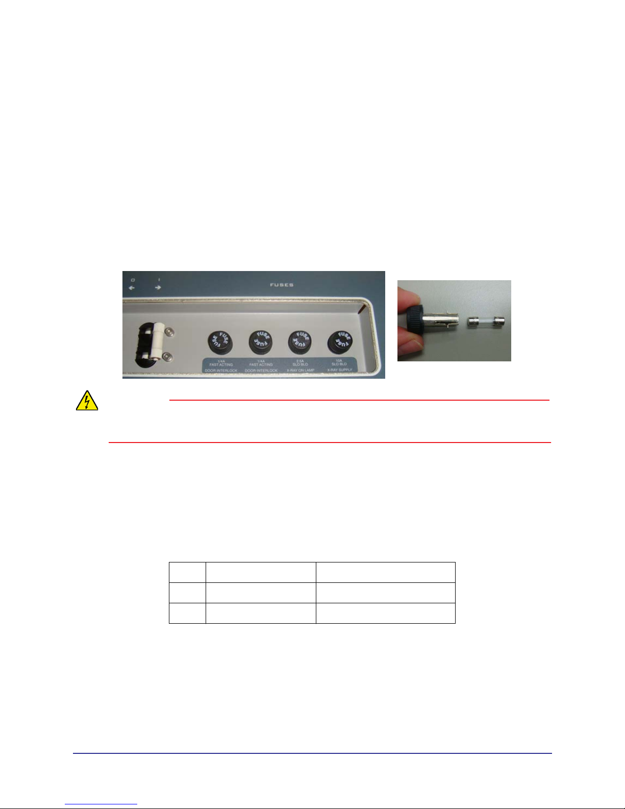
Replace External Fuses
Four external fuses are located on the back of the overhead.
WARNING
To avoid electrical shock, remove power from the system before removing fuses. Do not touch the
metal parts of the fuse holder until fully removed from the system. Touch the plastic cap only.
1. Press the OFF button on the operator control box. The scanner shuts down and the POWER
indicators on the operator control box and scanner go OFF.
2. At rear of overhead, switch circuit breaker to off position.
3. Using plastic cap, turn fuse holder counterclockwise and pull out.
4. Replace the fuse in the holder.
1, 2 Door Interlock 0.25A, 250V (fast acting)
3 Warning System 2.5A, 250V (slow blow)
4 X-Ray Power 10A, 250V (slow blow)
5. Align fuse holder in hole, push in and turn clockwise to secure.
032-0358-EN Rev B
1-1
Page 6
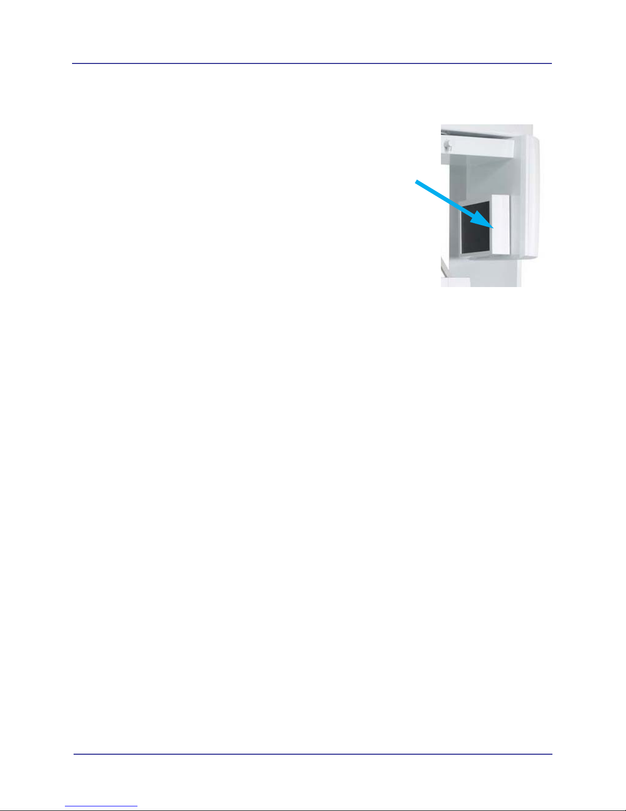
Panel Cover
The panel cover on the receptor panel fits very tightly over the
panel. If this panel cover is removed and re-installed for any
reason, perform the following:
• Crosshair Laser Adjustment
• Chair Calibration
• Centerline Laser Adjustment
• Geometric Calibration
Refer to the Installation Manual for instructions
Corrective Action
Panel
Cover
1-2
032-0358-EN Rev B
Page 7
Chapter
2
This chapter provides replacement part numbers. Ensure power is removed before servicing the scanner.
Illustrated Parts Breakdown
WARNING
High voltage is present in the scanner. Remove power from scanner before removing covers or
cables. To avoid personal injury from electrical shock, do not operate the system with any covers
open or cables removed.
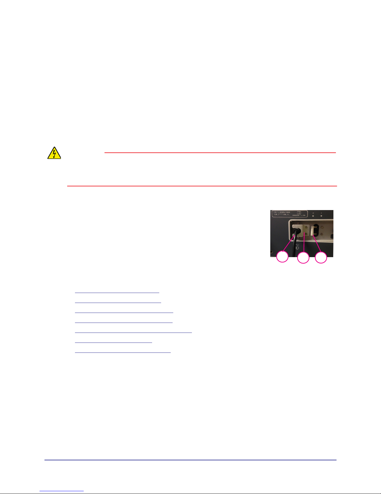
To ensure power to the scanner is locked out from the main supply:
1. At rear of scanner, turn circuit breaker off.
2. Remove the overhead cord bracket.
3. Unplug the scanner line cord.
4. Re-install overhead cord bracket so that line cord cannot be
plugged in.
3
1
2
The following assemblies are illustrated.
• System Assemblies (page 2-2)
• Overhead Assembly (page 2-4)
• Rotation Drive Assembly (page 2-6)
• X-Ray Source Assembly (page 2-8)
• Flip Receptor Panel Assembly (page 2-10)
• Chair Assembly (page 2-12)
• Upper Chair Assembly (page 2-14)
032-0358-EN Rev B
2-1
Page 8
KaVo OP 3D Vision Service Manual
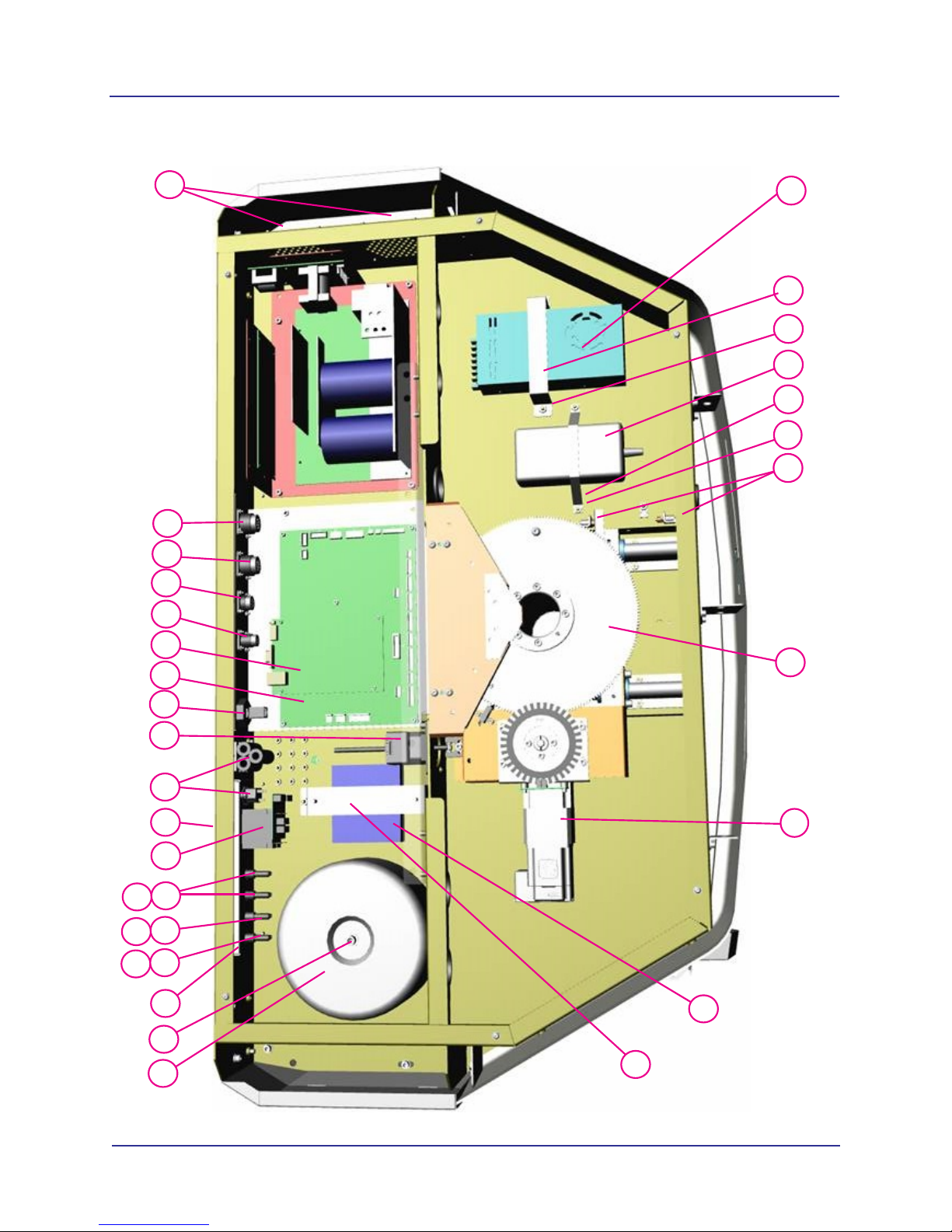
System Assemblies
13
12
11
1
3
2
4
5
6
10
2-2
7
8
9
8
7
032-0358-EN Rev B
Page 9

System Assembly Parts List
Item Part No. Description
1 1.007.6265 Wall Stabilizer (not shown)
2 1.006.5157 Upper Cover
3 BHCS #8-32 x 3/8 Long
4 1.013.0489 Resident Indicator Panel
5 1.011.1964 Receptor Assembly
6 1.013.1578 Chair Assembly
7 1.011.4086 Leveler - 3/8-16 LG HX BC 1000# Cap
8 0.830.0200 Leveler - 3/8-16 LG BC 1000# Cap
9 1.011.4014 Leveler - 3/8-16 LG HX SL1000# Cap
Illustrated Parts Breakdown
10 0.830.5669 Lower Plate Weldment
11 1.011.1954 X-Ray Source Assembly
12 1.007.4085 Laser Line Assembly
13 1.013.0173 Lower Cover Assembly
032-0358-EN Rev B
2-3
Page 10
KaVo OP 3D Vision Service Manual
Overhead Assembly
29
28
27
26
30
1
2
3
4
5
6
7
15
15
15
25
24
23
22
21
20
19
18
17
16
14
13
12
8
9
10
11
2-4
032-0358-EN Rev B
Page 11

Overhead Assembly Parts List
Item Part No. Description
1 1.006.3077 24V Power Supply
2 0.830.0360 Hook and Loop Fastener
3 #10-32 Nut
4 1.006.3078 2520 Varian Power Supply
5 0.830.0360 Hook and Loop Fastener
6 #10-32 Nut
7 1.007.1007 Limit Switches (set)
8 0.830.2548 Spindle Assembly
9 1.006.5842 Rotation Stepper Motor
10 0.830.0457 Network Switch and Power Cable
11 0.830.0360 Hook and Loop Fastener
12 0.830.1997 Toroid Isolation Transformer
13 SHCS 5/16-18 x 1 Long
14 1.010.0953 Power Bracket Assembly
15 1.007.4094 Buss #HTB-84M
16 1.006.3075 10A Fuse Digi-Key #F985-ND
17 1.006.3074 2.5A Fuse Digi-Key #F979-ND
18 1.006.3076 0.25 A Fuse Digi-Key #F939-ND
19 1.005.8617 10A/115VAC Circuit Breaker
20 1.007.4095 Fuse Label (not shown)
21 1.007.6324 Line Choke
22 1.005.8629 Platform Motor
23 1.007.6644 Ethernet Panel Mount Cable
24 1.005.8632 System Board
25 1.005.8624 Embedded Board
26 1.007.4097 Warning System External Cable Assembly
27 1.007.4098 Door Interlock External Cable Assembly
28 1.007.4099 Control Box External Cable Assembly
29 1.007.4100 Chair External Cable Assembly
30 1.007.4101 Overhead Fan (pair)
Illustrated Parts Breakdown
032-0358-EN Rev B
2-5
Page 12
KaVo OP 3D Vision Service Manual
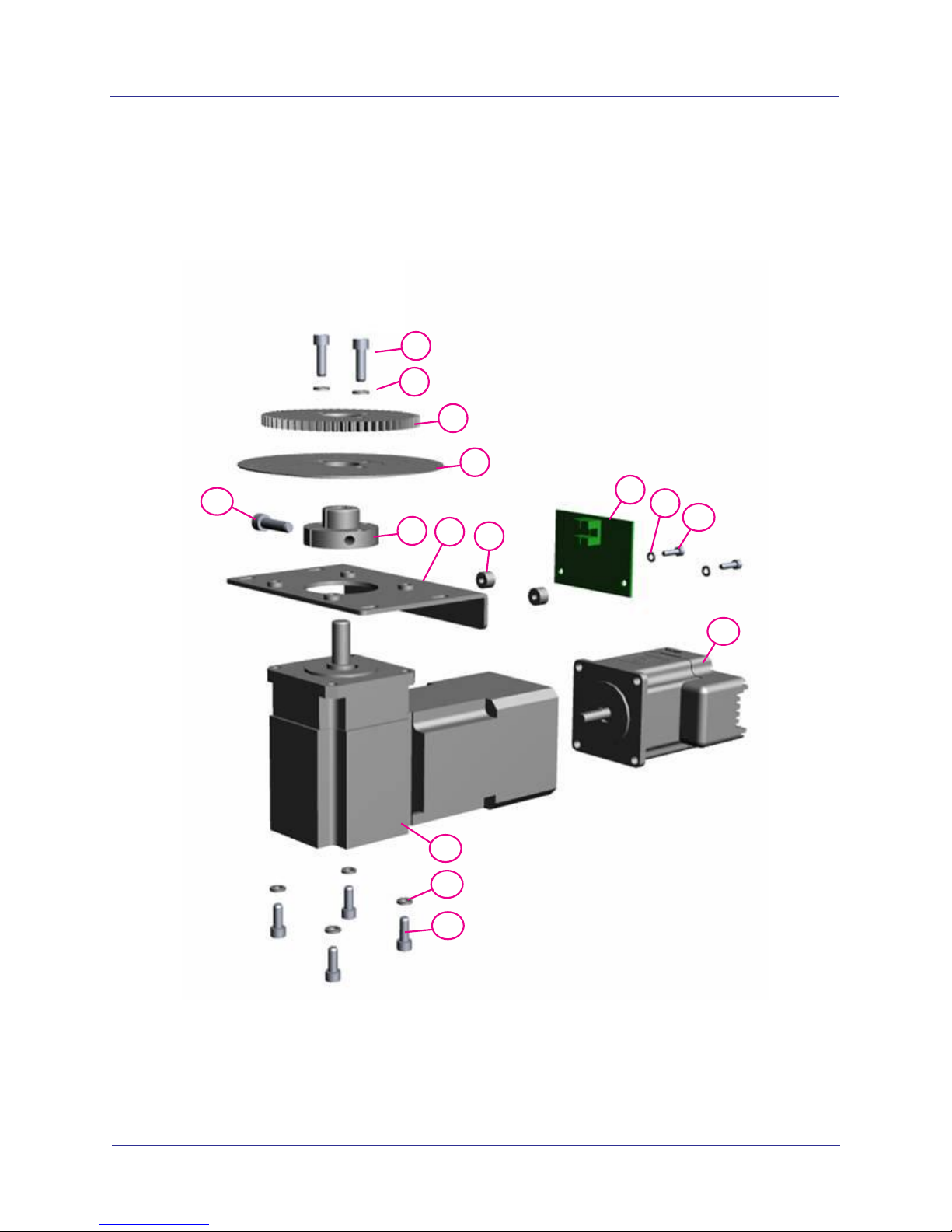
Rotation Drive Assembly
1
2
3
4
15
8
9
5
6
7
12
13
14
10
11
2-6
032-0358-EN Rev B
Page 13

Rotation Drive Assembly Parts List
Item Part No. Description
1 SHCS #10-24 x 5/8 Long
2 Split Washer #10
1.007.4102
3
1.006.8180
4
1.007.4105
5
1.007.4106
6
1.007.4107
7
1.007.3996
8
9 Split Washer #6
Drive Gear
Gear Encoder Disk
Gear Clamp
Rotation Motor Bracket
Al. Round Spacer
Gear Encoder
Illustrated Parts Breakdown
10 SHCS #6-32 x 1/2 Long
1.005.8631
11
12
1.007.5725
Stepper Motor
Thomson Micron #NTR23-025
13 Split Washer #10
14 SHCS #10-24 x 1/2 Long
15 SHCS #10-24 x 3/4 Long
032-0358-EN Rev B
2-7
Page 14
KaVo OP 3D Vision Service Manual
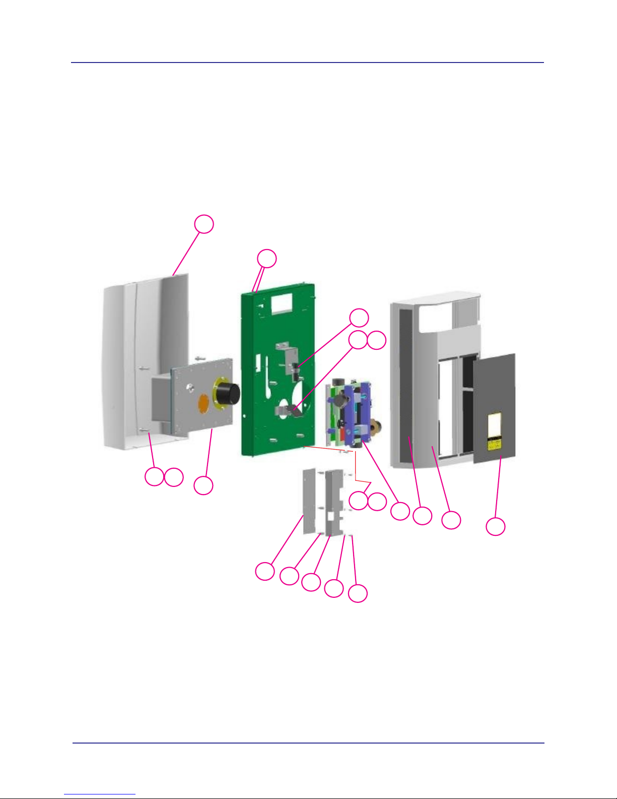
X-Ray Source Assembly
1
2
6
7
8
3
4
5
9
10
11
12
15
16
17
18
13
19
14
2-8
032-0358-EN Rev B
Page 15

X-Ray Source Assembly Parts List
Illustrated Parts Breakdown
1
Part No.
0.830.4966
Description
Rear X-Ray Source Cover Assembly
Item
2 BHCS #8-32 x 1/2 Long
3 SHCS 1/4-20 x 1 Long
4 Split Washer 1/4
1.005.8633
5
6
7
1.005.8622
0.830.0492
Tube Head Assembly
Cross Laser Assembly
Cross Laser Mirror
8 BHCS #6-32 x 1/4 Long
9 Split Washer #10
10 SHCS #10-24 x 3/8 Long
1.010.9900
11
12
13
1.013.0493
0.830.4965
Beam Limiter
Patient Align Panel
Front X-Ray Source Cover Assembly
1.006.5158
14
15
16
17
1.006.3236
1.007.4110
1.007.6278
Beam Limiter Panel
Beam Limiter Control PCB
#6-32 x 1/2 Long Standoff McMaster #91
Beam Limiter Board Shield
18 Split Washer #6
19 SHCS #6-32 x 1/4 Long
032-0358-EN Rev B
2-9
Page 16
KaVo OP 3D Vision Service Manual
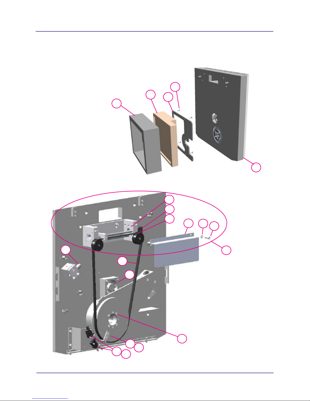
Flip Receptor Panel Assembly
Panel Side
1
4
2
3
5
8
9
10
6
14
15
11
12
13
7
Panel
Drive Side
20
16
18
17
19
2-10
032-0358-EN Rev B
Page 17

Flip Receptor Panel Assembly Parts List
Item Part No. Description
1 1.009.9646 Cover, Receptor Panel
2 1.009.9456 2520DX Receptor Panel
3 0.830.0627 Mounting Plate, Receptor 2520D
4 Flat Soc. Hd. M5
5 1.011.1955 Rear Receptor Cover Assy
6 1.007.4114 Stop Screw
7 1.007.4001 Drive Screw Assembly
8 SHCS M3 x 8mm Long
9 1.005.8630 Flip Stepper Motor
Illustrated Parts Breakdown
10 1.007.4003 Idler
11 1.007.4115 Cable Shield
12 Split Washer #10
13 SHCS #10-32 x 5/8 Long
14 1.007.4116 Belt McMaster #6484K511
15 0.830.0778 Flip Receptor Fan
16 1.007.4005 Belt Key
17 Flat Head Screw #8-32 x 3/8 Long
18 1.007.4007 Flip Receptor Limit Switch Assembly
19 SHCS #4-40 x 5/8 Long
20 SHCS #10-32 x 3 1/2 Long
032-0358-EN Rev B
2-11
Page 18

KaVo OP 3D Vision Service Manual
Chair Assembly
See Upper Chair Assembly
1
19
20
2 4
3
7
8
5
6
2-12
14
15
16
17
18
13
12
9
10
11
032-0358-EN Rev B
Page 19

Chair Assembly Parts List
Item Part No. Description
1.007.4118
1
1.006.6066
2
1.007.4119
3
1.007.4121
4
5 SHCS 1/4-20 x 5/8 Long
6 1/4 Split Washer
1.007.4122
7
0.830.2024
8
1.007.4125
9
Chair Receptacle Plate Assembly
Patient Alignment Board
Patient E-Stop External Cable
Chair Junction Cable
Rail
Slider Plate
Wheel
Illustrated Parts Breakdown
1.007.4126
10
11
12
13
14
15
16
1.007.4127
1.007.4128
1.013.1577
1.013.1576
1.007.6283
0.830.0362
Wheel Axle
Actuator Plate
Receptacle Flange
Assembly, Seat Bottom
Pad, Seat Bottom
Seat Frame
Plastic Spacers
17 M6 Split Washer
18 SHCS M6 x 45mm Long PHP ZN
1.013.1579
19
20
1.011.8381
Seat Pad, Back
Bracket, Chair Mounting
032-0358-EN Rev B
2-13
Page 20

KaVo OP 3D Vision Service Manual
Upper Chair Assembly
45
1
2
3
4
5
6
7
8
44
43
42
41
37
40
39
23
38
24
25
26
27
16
17
18
9
10
11
12
13
14
15
19
20
21
22
36
35
34
33
2-14
28
29
30
31
32
032-0358-EN Rev B
Page 21

Upper Chair Assembly Parts List
Item Part No. Description
1.007.3598
1
1.007.3029
2
3 Nylon Flat Washer 5/16 ID - 3/4 OD
1.007.4135
4
5 SS 5/16-18 x 1.25 Long
6 SHCS 1/4 - 20 x 5/8 Long
7 Flat Washer 1/4
1.007.4136
8
9 SHCS #8-32 x 1/2 Long
1.007.4137
10
11 Flat Head 1/4-20 x 1/2 Long
1.007.1675
12
1.007.1676
13
14 Split Washer 1/4
15 SHCS 1/4-20 x 5/8 Long
0.830.1440
16
17 Split Washer #10
18 SHCS #10-32 x 5/8 Long
19 SHCS 1/4-20 x 1 1/4 Long
20 Split Washer 1/4
21 Flat Washer 1/4
0.830.4997
22
1.007.4140
23
1.007.4010
24
1.007.4141
25
26 SHCS #10-24 x 1/4 Long
1.006.8102
27
1.007.4142
28
29 BHCS #6-32 x 1/4 Long
1.007.4143
30
31 SHCS #6-32 x 1/2 Long
1.007.4144
32
33 SHCS 1/4-20 x 5/8 Long
1.012.7078
34
35 Dowel Pin 1/4 x 1 Long
0.830.4998
36
1.007.4147
37
1.007.4152
38
39 SHCS #10-32 x 3/4 Long
0.830.4993
40
41 Bronze Bushing .375 ID x .625 OD x .50 Long
1.007.4154
42
1.007.4155
43
1.007.4156
44
0.830.4994
45
Clamp Knob
Support Plate
Clamp Plate
Slider Block
Roller Plate
Left Cap Plate
Right Cap Plate
Bearing V Guide Dual-Vee #W1
Hinge Bar
Bunting #BM4971
Tee Nut
Magnet Plate
Gate Label
Upper Guide
Lower Guide
3/8 Spring Plunger McMaster Carr #8499A85
V-Series Slide Block
Gate
Gate Pivot Pin
Glide
Clamp Handle
Clamp Washer
Lock Shaft
Hand Knob, Lobed
Arm
Illustrated Parts Breakdown
032-0358-EN Rev B
2-15
Page 22

KaVo OP 3D Vision Service Manual
2-16
032-0358-EN Rev B
Page 23

Chapter
3
Software Backup and Restore,
Recovery, and Updates
Backup and Restore
FBackup is a utility for backing up and restoring files on the scanner controller. The utility has both a Backup
wizard and a Restore wizard that walks you through the process of selecting the files and location for each
operation. Refer to the online help within FBackup for more information.
Also, user accounts that have been added by the site need to be manually copied and restored. This data
is not stored in the two files above.
The recommended workflow is to use a USB-connected device (USB Flash Drive or external drive with a
USB connection) as the storage media. The following folders contain site-specific files that should be
backed up:
• Imagers
• Data
NOTE: If you are using a USB Flash Drive (UFD), be sure it has enough storage space to hold the files being
backed up.
Backup Files
1. Install USB-connected device to a
USB port on the scanner controller.
2. Login with Service account and select
Backup & Restore from menu.
3. Select New to create a new backup
job.
032-0358-EN Rev B
3-1
Page 24

KaVo OP 3D Vision Service Manual
4. On the New Backup Wizard,
complete the following:
a. Enter a name for the backup
job.
b. Select Local to save to the
USB device.
c. Select drive location of the
USB device.
d. To save backup files to a
specific folder, browse to
desired folder location.
Otherwise, a folder will be
created on the media with the
backup job name.
e. Select Next.
5. Select folders to be backup
up:
a. Select Add Folder.
b. On pop-up window, select
Computer, the select
Imagers (D:). Press OK.
c. Repeat above step and
select Data (E:). Press
OK.
d. Press Next.
3-2
032-0358-EN Rev B
Page 25

6. Ensure Make Full and Encrypt No
options are selected. Press Next.
7. Ensure Manually option is
selected. Press Save, then select
Save and run. Backup job
parameters are saved and job
executes. A progress bar is
displayed at the bottom of the
window.
NOTE: The duration of the backup
operation will vary depending on
the amount of data being backed
up.
Software Backup and Restore, Recovery, and Updates
8. When backup job completes, Last
backup status field will indicate
status.
NOTE: To view a log of the
backup operation, select View ->
Job Logs -> Last Backup Log. The
log may indicate that one file was
skipped. This is the System
Volume file, which cannot be
copied because permission is
denied. It is not necessary to
backup this file.
9. Un-install USB-connected device
and label media.
032-0358-EN Rev B
3-3
Page 26

KaVo OP 3D Vision Service Manual
Restore Files
1. Install USB-connected device
containing the files to be restored
to a USB port on the scanner
controller.
2. Select Backup & Restore from
menu.
3. Select backup job to be restored
from left side of window.
4. Press Restore.
5. On Restore Wizard, ensure the
following defaults are selected:
• Use original location
• Restore the latest version of
all files
6. Press Finish. Restore begins.
You may be prompted to confirm
overwriting of files.
NOTE: The duration of the restore
operation will vary depending on
the amount of data being restored.
7. A progress bar is displayed at the
bottom of the window. When
complete, select View -> Job Logs
-> Last Restore Log view a log of
the restore operation.
NOTE: If any errors are encountered during the restore, a pop-up displays with an option to view
the log file.
8. Un-install USB-connected device.
Backup and Restore User Account Data
Currently, the only way to backup user accounts that have been added by the site is to manually copy
the account names and then recreate the accounts after the operating environment has been restored.
Recreated accounts will have to be assigned default passwords, that can later be changed to a
password selected by the user.
3-4
032-0358-EN Rev B
Page 27

Software Backup and Restore, Recovery, and Updates
Restore Operating Environment
The operating system image on the scanner controller (model 800137) is pre-loaded at the factory. Sites
receive a USB Flash Drive (UFD) of this image. Follow the procedures below in case the operating
environment must be restored.
Boot the Scanner Controller from the Bootable UFD
1. Insert the bootable UFD into an available USB port on the scanner controller.
2. Boot the scanner controller (power off/power on) to the BIOS setup screen by pressing the Delete
key at the beginning of the boot sequence, typically when the SmartScan STUDIO splash screen
is displayed and beeps are audible. You may want to press Delete several time when the splash
screen is displayed to ensure entry into the BIOS setup screen.
3. Press the Right Arrow key until the BOOT options tab is selected, and then press the Up Arrow
key to select the Hard Drive BBS Priorities option.
4. Press the Enter key twice to access the hard drive boot options. Use the Down Arrow key to select
the UFD entry (indicated by the device description of the UFD).
5. Press the Enter key to select the UFD.
6. Press the F4 key to display a save dialog, then select Yes and press the Enter key to save the
change and initiate a reboot. The scanner controller will reboot from the UFD.
7. From this point, continue with one of the following operations:
•
Install the Operating System Image (page 3-5)
• Make a Backup Copy of the Software Package onto a Blank UFD (page 3-9)
Install the Operating System Image
NOTE: The touch screen interface is not active in this application. Attach a mouse or use keyboard
commands (tab to move between fields, up and down arrow keys to make selections in a field,
space bar or Enter key to enter).
1. Obtain the bootable UFD and follow instructions in Boot the Scanner Controller from the Bootable
UFD (page 3-5).
2. After the scanner controller has booted from the
UFD, the Installation Progress Monitor is displayed,
followed by a window with the message: Verifying
packages. Wait (about five minutes) until the
message Package verification passed is
displayed and options on the window become
active. If package verification fails, obtain a new
bootable UFD.
3. Select Install from the Select Action drop-down
menu.
032-0358-EN Rev B
3-5
Page 28

KaVo OP 3D Vision Service Manual
4. Select Start. A warning is displayed that the disk will be erased on the PC.
5. Select Continue. A message displays stating the disk will be erased.
6. Select Continue again. The disk is erased and software installation begins.
7. After the software is written to the internal
hard drive, remove the UFD from the USB
port.
8. Select Quit. The scanner controller will
reboot and start first-time boot processing
(5-10 minutes). It will reboot again.
NOTE: Failure to remove the UFD will
cause the scanner controller to boot from
it again. In this case, remove the UFD and
turn the scanner controller off, then on.
9. When the Login screen is displayed, log in using the Service account and select Explorer from the
menu. Check to see if Imagers is empty:
a. Navigate to Imagers (typically D drive). Check for a folder named for the serial number of the
detector panel (for example: E259-04B). If this file exists, installation is complete. Otherwise,
continue with step b.
b. Obtain the Imagers DVD for the panel. Obtain an external DVD drive or copy the DVD
contents to a UFD.
c. Navigate to the Imagers content on the DVD or UFD.
d. Start Setup.exe and follow instructions.
Software Updates
To check the current software version on the scanner controller , select on the login screen. To perform
a software update, use the following procedures:
• Update Scanner Controller Software to Latest Version (page 3-6)
• Update Clinical Software (page 3-7)
Update Scanner Controller Software to Latest Version
1. Insert the bootable UFD into an available USB port on the scanner controller.
2. Login to SmartScan STUDIO using the Service Account.
3. Select Upgrade from the menu. The system searches for the update package, then displays the
package information.
4. Verify the listed update is correct, then select . A status window is displayed with Setting Up
Package selected. This process may take about 5 minutes to complete.
5. When the package set up is complete, the update window displays with the message: Verifying
packages. Wait until the message Package verification passed is displayed and options on the
window become active. If package verification fails, obtain a new bootable UFD.
3-6
032-0358-EN Rev B
Page 29

Software Backup and Restore, Recovery, and Updates
6. Select Upgrade from the Select Action drop-down menu.
7. Select Start. A warning is displayed that the inactive partition on the PC will be erased.
8. Select Continue when prompted. The software update continues and status is displayed.
9. Review status messages as needed. When the Quit button becomes active, select Quit.
10. Select to reboot and complete update. The scanner controller will reboot and start first-time
boot processing (5-10 minutes). It will reboot again, and perform checks and configuration, then
display the Login screen. No manual system configuration is required since the previous
configuration has been maintained.
11. Remove the UFD from the USB port.
12. A unique software license is now required to establish the accessible field of view on the V-series
upgradeable scanners. A license file is included on the installer media that should contain the
unique license. If the license is missing, you will not be able to access the protocol screen in
SmartScan STUDIO.
a. Log in, select Acquire from the menu, and navigate to the Protocol screen.
b. Check that the screen is accessible and that the protocols displayed are for the correct
system. Refer to the appropriate User Manual for a list of protocols for each system.
c. Contact Technical Support if a license is required.
13. Perform updates to clinical software installed at the site. See Update Clinical Software (page 3-7).
Update Clinical Software
Clinical software at the site must be updated to the most current versions after the scanner controller
software is updated. Access Control Panel at each site workstation to view the current clinical software
versions loaded.
CAUTIONCAUTION
It is REQUIRED that the most current versions of the clinical software are installed after the
scanner controller is updated. The software checks for mismatched versions. A database error will
be indicated on the SmartScan STUDIO Manager status display if versions do not match.
All servers and client workstations must be running one of the following operating systems. The update
software performs a check, and will not continue if the computer is not running one of these operating
systems.
• Windows
• Windows
• Windows
• Windows
• Windows
• Windows
• Windows
®
7 Professional, Ultimate, and Enterprise (64-bit) SP1
®
8.1 Pro and Enterprise (64-bit)
®
10 Pro and Enterprise (64-bit)
®
Server 2008 R2 SP1
®
Server 2012 (all versions)
®
Server 2012 R2 (all versions)
®
Server 2016 (all versions)
032-0358-EN Rev B
3-7
Page 30

KaVo OP 3D Vision Service Manual
Prior to beginning the update, ensure that the system is operational and all network connections exist
and are valid. Previous settings and locations are retained, so it is important to know that the system is
fully operational before beginning the update.
Follow the installation procedures in the Installation Manual to update clinical software that is required
at the site. Clinical software should be updated in the following order:
• SmartScan STUDIO Integration Services (all sites)
• DEXIS i-CAT FLX Server Plugin (DEXIS-FLX sites only)
• DEXIS i-CAT FLX Client (DEXIS-FLX sites only)
• SmartScan STUDIO Manager (all sites)
NOTE: Any non-default permissions set for the SmartScan STUDIO Integration Services
services are deleted during an update and will need to be reset.
Copy a License File for V-Series Upgradeable Systems
1. If license file is on a USB, insert USB into an available USB port on the scanner controller.
2. Login to SmartScan STUDIO using the Service Account.
3. Select Licenses from the menu.
4. For license files on the USB, available license files are displayed. Select license to copy, then press
.
5. For license files located in a download folder or on a network drive:
a. Press .
b. Select Download Folder, then select license file. Or, select Network Path, enter the path of
the license file location and select the license file.
c. Press .
6. The message License files copied successfully is displayed when complete. Press to
return to the menu.
7. Perform Panel Cal, Shutter Cal, and Geo Cal. Refer to the Installation Manual for instructions.
3-8
032-0358-EN Rev B
Page 31

Software Backup and Restore, Recovery, and Updates
SmartScan STUDIO Manager Status Indicators
SmartScan STUDIO Manager displays three status indicators in the top, righthand corner of the display . Move the mouse over the indicator to display more
detail about the status condition.
Scanner - indicates status of the connectivity between the workstation
running SmartScan STUDIO Manager and the scanner controller.
Database -
• The first indicator shows status of the communication between
the workstation running SmartScan STUDIO Manager and the
SmartScan STUDIO Integration Services web service.
• The second indicator shows status of the communication
between the workstation running SmartScan STUDIO Manager
and the Image Root folder.
If a status check fails, the status indicator changes to a red X.
Refer to Installation Manual for more information on troubleshooting failed
status indicator conditions. Contact Technical Support if problem is not
corrected or the error persists.
Make a Backup Copy of the Software Package onto a Blank UFD
NOTE: The touch screen interface is not active in this application. Attach a mouse or use keyboard
commands (tab to move between fields, up and down arrow keys to make selections in a field,
space bar or Enter key to enter).
1. Insert the bootable UFD into an available USB port on the scanner controller.
2. Follow instructions in Boot the Scanner Controller from the Bootable UFD (page 3-5).
3. After the scanner controller has booted from the
UFD, the Installation Progress Monitor is displayed,
followed by a window with the message: Verifying
packages. Wait (about five minutes) until the
message Package verification passed is
displayed and options on the window become
active. If package verification fails, obtain a new
bootable UFD.
4. Select MakeUFD from the Select Action drop-down
menu.
5. Insert a blank UFD into an available USB port.
6. Select the correct drive letter for the blank UFD from the UFD drop-down menu.
7. Select Start. You are prompted to ensure a blank UFD is attached.
8. Select Continue. A warning is displayed that all contents will be lost on the UFD.
032-0358-EN Rev B
3-9
Page 32

KaVo OP 3D Vision Service Manual
9. Select Continue. A message is displayed that the UFD drive will be erased, and the software will
be copied.
10. Select Continue. The UFD is erased, then the copy operation begins.
NOTE: The copy operation takes approximately 30 minutes, depending on the size of the update.
11. When the copy is complete, a success message is displayed. Select Continue.
12. Remove both UFDs from the scanner controller.
13. Select Quit. Installation Progress Monitor is displayed briefly, followed by a message stating no
update was performed.
14. Select . The scanner controller will reboot to the Login screen.
SmartScan STUDIO Manager Settings Window
In addition to providing options for configuring SmartScan STUDIO Manager (described in Installation
Manual), the Settings window also contains the product version and a rescan option.
In SmartScan STUDIO Manager, select to access the Settings window.
Product Version
Starting with version 2.1, the current installed version number of SmartScan STUDIO Manager can be
found on the Settings window.
Rescan
The Rescan option rebuilds the patient exam list database. Use this option if it is suspected that the
exam list is corrupted. Depending on the size of the database, this can be a time-consuming operation.
3-10
032-0358-EN Rev B
Page 33

Chapter
4
Service Account Menu
Log In
Service personnel are assigned specific service account access when logging into SmartScan STUDIO on
the scanner controller. To log in:
1. Enter your user name and password.
2. Press to log into service menu.
Option Purpose
Acquire exam images and access Utilities. Refer to Technical Guide for
Acquire
Exam List Access utility to add, update, delete and view status of exams.
Configurator Access user account management, network information, file maintenance, and
instructions on performing Calibrations and QA tests.
export dose logbook and activity logs. Refer to Technical Guide.
Technical Support Access Technical Support website.
Remote Assistance Access website for remote Helpdesk assistance.
Backup & Restore Access FBackup for backing up or restoring files on the scanner controller.
Refer to Software Backup, Recovery, and Updates.
Explorer Displays Windows Explorer.
Control Panels Displays Windows Control Panel.
Upgrade Initiate a software update.
Licenses Copy a license file to the scanner controller.
Analytic Options Select options to opt out of analytics mode or software download updates.
Send Logs Send system logs to the factory for troubleshooting purposes.
IEC Displays command line window for entering IEC commands. Refer to IEC
Command Codes for information.
Vendor Diagnostics Access utility for vendor diagnostics.
Viva Displays Varian Image Viewing and Acquisition application used with the
sensor panel.
Set Support URLs Set the webpage URLs for technical support and remote assistance for the
region of the world for the scanner.
Date and Time Change system date, time and time zone.
032-0358-EN Rev B
4-1
Page 34

KaVo OP 3D Vision Service Manual
Run Utilities
1. Select Acquire from the menu.
2. Press to access Utilities menu.
Option Description
PanelCal
Refer to Installation Manual.
ShutterCal
ChairCal
GeoCal
QA Line Pair
QA Material
QA Air Water
QA Pan
Reprocess Exam Refer to User Manual.
Favorites Manager Refer to User Manual.
Roll-off Roll-off is used for field of view collimation testing.
Roll-Off
Roll-off is used for field of view collimation testing and checks that the extents of the field of view are
visible. It can be run for both Full Beam (landscape) and Half Beam (portrait) orientation.
1. Perform both a PanelCal and a ShutterCal, described earlier in this chapter.
2. Select Roll-off and press .
3. Remove all objects from the field of view.
4. Select desired orientation (Full Beam or Half Beam) and press .
5. To fine-tune adjust the beam limiter shutter collimation amount, enter roll-off values as desired for
top, bottom, left and/or right borders. Each border can be independently adjusted. Positive values
shift the collimation out; negative values shift the collimation in.
6. Press to initiate a scout scan. Review scout scan for evidence of beam limiter shutter
collimation on all four borders.
NOTE: For Full Beam, two scout scans are taken in landscape position. For Half Beam, one scout
is taken in portrait position.
• Make note of any test configuration that requires roll-off adjustment greater than 10.00 (mm)
vertically or horizontally in either direction (plus or minus).
• Make note of any test configuration that does not show evidence of beam limiter shutter
collimation.
7. When scout scans are complete, press to continue with additional roll-off testing or
to exit.
4-2
032-0358-EN Rev B
Page 35

Chapter
5
IEC Command Codes
Home Commands
HB Home Beam Limiter
Homes all four shutters; right, left, top and bottom. At the completion of this
command the shutters are all open and at a position of zero.
Upon completion of the HB command it is recommended to move all four shutters
to a position of 10 steps. This avoids a potential lockup issue on version 4 of the
Beam Limiter assembly once powered off.
HP Home Platform
Homes the platform axis to the rear of the gantry and sets the position to 1500.
HFR Home Rotation Fast
Homes the rotation drive from any location such that the Tube-Head and Beam
Limiter assembly are located perpendicular to patients’ right when seated. This
position is then set to be 100000 in stepper motor space. Subsequent
MR 100000 commands will move back to this position.
HSR Home Rotation Short
Performs a quick check within approximately 1 degree of the current location for
home. If home is not located, the rotation proceeds to perform an HFR. If the
rotation is already home, this command will complete much more quickly.
Movement Commands
MB Move Beam Limiter right left top bottom shutter
Command syntax: MB right left top bottom (Example: MB 700 700 3000 1500)
Right, Left and Bottom shutters: 0 to 2900
Top shutter: 0 to 3300
MP Move Platform
Command syntax: MP Target Speed (Example: MP 1500 1500)
Target: 1500 to 100000
Speed: 1000 to 54000
MPM Move Platform in mm
Command syntax: MPM Target Speed (Example: MPM 20 1500)
Target: 0 to 90 mm (home position is zero-absolute)
Speed: 1000 to 54000
MPP Move Panel Position
Command syntax: MPP Position Type
(Example: MPP 1 0 (Half-Beam))
Position: 0 = Full-Beam (Landscape), 1 = Half-Beam (Portrait)
Type: 0 = large field of view, 1 = medium field of view
032-0358-EN Rev B
5-1
Page 36

KaVo OP 3D Vision Service Manual
MR Move Rotation
Command syntax: MR Distance Speed (Example: MR 35000 1000)
Distance: 35000 to 733333
Speed: 1000 to 65000
MRD Move Rotation in Degrees
Command syntax: MRD Target Speed (Example: MRD 180 1000)
Target: -40 to 430 degrees
(home position is equal to zero degrees - absolute)
Speed: 1000 to 65000
Read Commands
RB Read Beam Limiter
Returns a four digit position of each shutter (right, left, top, bottom) in stepper motor
positions in the following format.
Return Value = OK r:xxxx l:xxxx t:xxxx b:xxxx
RD Read Door Status
0 = Closed and 1 = Open
RE The Read Exception register command returns a 13-bit integer of packed bits
indicating which exceptions are set.
Results returned in format: OK xxxx
The table below shows the values for the occurrence of each exception as a single
occurrence. Most often more than one exception occurs at a time such as all three
“not home/initialized” exceptions. In the case of the three “not home/initialized”
exceptions, occurring at the same time the return value would be 448. These
exceptions are unique in that they occur at any time when their respective motors are
not in the home position; which occurs practically any time the machine is in use. For
example if a stall occurs it will do so because the rotation is moving with the platform
and shutters moved into position for a patient scan. Therefore, the stall exception
typically returns an exception value of 450 instead of the signature value of 2.
Bit Binary Value Decimal
N/A 0b 0000 0000 0000 0000 0 No Exceptions
1 0b 0000 0000 0000 0001 1 Emergency Stop activated
2 0b 0000 0000 0000 0010 2 Stall Detected
3 0b 0000 0000 0000 0100 4 X-ray Tube Short
4 0b 0000 0000 0000 1000 8 X-ray watchdog Time-out
5 0b 0000 0000 0001 0000 16 Linux watchdog error
6 0b 0000 0000 0010 0000 32 X-ray Fault from the X-ray controller
7 0b 0000 0000 0100 0000 64 Platform needs to be homed
8 0b 0000 0000 1000 0000 128 Rotation needs to be homed
9 0b 0000 0001 0000 0000 256 Beam Limiter Not Initialized
10 0b 0000 0010 0000 0000 512 Machine is turned off
11 0b 0000 0100 0000 0000 1024 Door was opened during an X-ray exposure
12 0b 0000 1000 0000 0000 2048 Ethernet cable was disconnected during an exposure
13 0b 0001 0000 0000 0000 4096 Panel Position error – both limits reading high or low
5-2
Description
Value
032-0358-EN Rev B
Page 37

IEC Command Codes
RI The Read Input register command returns a 23-bit integer of packed bits indicating
which inputs are set.
Results returned in format: OK xxxx
The table below documents the values for the occurrence of each input as a single
occurrence. More than one may be set at any given time.
Bit Binary Value Decimal
Description
Value
N/A 0b 0000 0000 0000 0000 0000 0000 0 No Inputs
1 0b 0000 0000 0000 0000 0000 0001 1 Emergency Stop activated
2 0b 0000 0000 0000 0000 0000 0010 2 Machine On Switch
3 0b 0000 0000 0000 0000 0000 0100 4 Machine Off Switch
4 0b 0000 0000 0000 0000 0000 1000 8 Scan Enable button status
5 0b 0000 0000 0000 0000 0001 0000 16 X-ray controller error
6 0b 0000 0000 0000 0000 0010 0000 32 Encoder direction
7 0b 0000 0000 0000 0000 0100 0000 64 Rotation optical switch status
8 0b 0000 0000 0000 0000 1000 0000 128 Rotation limit switch
9 0b 0000 0000 0000 0001 0000 0000 256 Rotation Start of travel status
10 0b 0000 0000 0000 0010 0000 0000 512 Rotation End of travel status
11 0b 0000 0000 0000 0100 0000 0000 1024 Platform Start of travel status
12 0b 0000 0000 0000 1000 0000 0000 2048 Platform End of travel status
13 0b 0000 0000 0001 0000 0000 0000 4096 Door signal
14 0b 0000 0000 0010 0000 0000 0000 8192 Panel horizontal (Landscape / Full-Beam)
15 0b 0000 0000 0100 0000 0000 0000 16384 Panel vertical (Portrait / Half-Beam)
16 0b 0000 0000 1000 0000 0000 0000 32768 Machine power status
17 0b 0000 0001 0000 0000 0000 0000 65536 Right shutter limit switch
18 0b 0000 0010 0000 0000 0000 0000 131072 Left shutter limit switch
19 0b 0000 0100 0000 0000 0000 0000 262144 Top shutter limit switch
20 0b 0000 1000 0000 0000 0000 0000 524288 Bottom shutter limit switch
21 0b 0001 0000 0000 0000 0000 0000 1048576 Panel flip motion, moving signal
22 0b 0010 0000 0000 0000 0000 0000 2097152 Rotation motion, moving signal
23 0b 0100 0000 0000 0000 0000 0000 4194304 Platform motion, moving signal
RMS Read Usage Monitors command returns a quantity of time (usage) for the
requested component.
Results returned in format: OK xxxxdxxhxxmxxs containing the days, hours,
minutes and seconds the component has been in use.
Command syntax: RMS n
0 Beam Limiter Motors
1 Embedded Board
2 Panel
3 Platform Motor
4 24V Power Supply
5 Rotation Motor
6 X-ray
7 Flipper Motor
032-0358-EN Rev B
5-3
Page 38

KaVo OP 3D Vision Service Manual
RP Read Platform position = Reads the platforms stepper motor position.
Results returned in format: OK xxxxx
The home position is the back of the gantry with a position of 1500. Front on the
large field of view is ~70,000 and on the medium field of view it is ~79,000. Each
millimeter of distance will move the motor 1,008 steps.
RPP Read Panel Position - Reads the panel position
Results returned in format: OK n
0 Error (Both limit switches are open)
1 Half-Beam / Portrait mode
2 Full-Beam / Landscape mode
3 Error
RR Read Rotation
Reads the rotation position in stepper motor space.
Results returned in format: OK xxxxxx
One degree of distance is approximately ~1481.50 steps in stepper motor space.
Exceptions do apply, namely when moving to negative target degree locations. The
full range of motion in motor space is 35000-733333 or in degrees -40 through 430.
RX Read X-ray Setup - reads the X-ray Setup register based on the requested KV
range setting.
Command syntax: RX n
0 = 120 KV Range (default) 1 = 90 KV Range
Results returned in format:
OK kV mA TicksPerFrame XrayOn XrayOff PanelRead PulseMode
Set Commands
SP Sets platform position - Sets the counts of the platform.
Command syntax: SP n
n = 0 to 65000
The “HP” (home platform) command moves the platform to the rear of the gantry
and then sets the position to 1500. The position once moved to the rear could be
“set” to 0 using this command. In general, this command is used internally by the
embedded firmware.
SR Sets rotation position - Sets the counts of the rotation.
Command syntax: SR n
n = 35,000 to 733333
The “HFR” (home fast rotation) command moves the rotation to the limit switch.
This location is then set to 100,000. This position, once moved, could be “set” to
50,000 using this command. In general, this command is used internally by the
embedded firmware.
SX Set X-ray
Command syntax:
SX kV mA TicksPerFrame XRayOn XRayOff PanelRead PulseMode TubeRange
kV: 80 to 126 in increments of 2 only
mA: 0 = 3mA, 1 = 5mA, 2 = 7mA
Ticks Per Frame: 50,000,000 to 833,333
50 MHz/Ticks per frame (1-60 frames/sec). Number of 50Mhz clock cycles per
frame. Therefore, frame time equals Ticks Per Frame * 20(ns).
5-4
032-0358-EN Rev B
Page 39

IEC Command Codes
X-ray On: Typically equals 1. 0 to (Ticks per frame - 1)
X-ray Off: Greater than X-ray On and less than (Ticks per frame - 1)
Set as needed for desired length. 50,000 = 1 (ms)
Panel Readout: 0 to (Ticks per frame - 1). Typically set the same as
X-ray Off, except for continuous X-ray mode.
Pulse Mode: 0 or 1. If not entered, defaults to 0.
0 = 200 microsecond pulse for panel blanking and valid frame.
1 = either a 5msec pulse for valid frame or 3msec for panel blanking
Tube Range: If not entered, defaults to zero.
0 = 120 KV tube, 1 = 90 KV tube
X-Ray Commands
XCN Performs a cine X-ray acquisition for the number of frames requested at the
‘Ticks Per Frame’ rate as setup in the X-ray register.
Command syntax: XCN Frames Watchdog
Frames: 1 to 1024
Watchdog: 0 = disabled, 1 = enabled
XCT Perform a CT scan for requested distance, speed, and watchdog settings.
Command syntax: XCT Distance Speed Watchdog
Distance: 1000 to 668563
Speed: 1000 to 65000
Watchdog: 0 = disabled (default), 1 = enabled
XIP Performs a Panoramic scan for the requested parameters.
Command syntax: XIP Distance Speed PlatformOffset PlatformStartSpeed
PlatformStopSpeed RampReduction Watchdog
Distance: 1000 to 668563
Speed: 1000 to 70000
Platform Offset: 1 to (Distance - 25000)
Platform Start: 1000 to 54000
Platform End: 1000 to 54000
Ramp Reduction: 0 to 250
Watchdog: 0 = disabled, 1 = enabled
XP Performs an exposed X-ray acquisition for the number of frames requested at the
‘Ticks Per Frame’ rate as setup in the X-ray register.
Command syntax: XP Frames Watchdog
Frames: 1 to 1024
Watchdog: 0 = disabled, 1 = enabled
Miscellaneous Commands
BD Get Board Information
Command syntax: BD
Retrieves the board component versioning.
Results returned in format: OK KRL:x UBT:x FID:x SWB:x
KRL: Linux kernel version (short)
UBT: U-Boot version (short)
FID: 1210 Board Flash (EEPROM) Chip System ID
SWB: ROMFS Software Build version (HG-ID Date Time)
032-0358-EN Rev B
5-5
Page 40

KaVo OP 3D Vision Service Manual
CE Clear Exception Register
Command syntax: CE
Note that the exception register will not reset, if the exceptional condition is
persisting regardless of the request to clear the register. This is most commonly
observed when one of the motors is not in the home position.
CS Cancel Scan Enable
Command syntax: CS
Clears the control box ready scan button when enabled, effectively canceling the
current scan. Performed via a separate TCP connection on port 1024; due to the
current WSB command blocking on the port where the scan was initiated.
DUMP Performs the following series of commands, with the responses for these
commands formatted as a single dump response for convenience:
Door (RD), Exceptions (RE), System Versions (GS), and Usage Monitors (RMS).
Command syntax: DUMP
GS Get System Information
Command syntax: GS
Results returned in format: OK mv:x hw:x sw:x bv:x sn:x
mv: Machine Version, hw: Hardware Version, sw: Software Version
bv: Beam Limiter Version, sn: Machine Serial Number
Fifth Digit Machine Type
1 Next-Generation medium field of view
2 Smart-Scan medium field of view
8 Next-Generation large field of view
9 Smart-Scan large field of view
RSN Read Serial Number
Command syntax: RSN
Reads the currently configured system serial number of the 1210 board.
Results returned in format: OK xxxxxx
The default system serial number for a board that has not been configured is
080000
SSN Set Serial Number
Command syntax: SSN cccccc
Sets the system serial number of the 1210 board to the requested six character
value, where cccccc is the serial number.
Results returned in format: OK
The default system serial number for a board that has not been configured is
080000
WSB Enable Scan Button
Command syntax: WSB
Enables the wait for ready scan button on the control box; soliciting the user to
initiate a scan. Times out in two minutes if the scan button is not pressed.
QUIT Closes the telnet session.
Command syntax: QUIT
5-6
032-0358-EN Rev B
Page 41

Chapter
6
Safety Checks
Recommended Safety Checks
The safety checks in this chapter must be performed on systems installed in locations that must comply with
VDE 0751-1 and/or IEC 62353 standards. They are recommended for all other installations.
Safety checks are required by standard after:
• System Repair
• Recurrent Maintenance and Interval (2 years)
• System Modifications
• Initial Installation
Qualified personnel must perform these tests. Qualifications include training on the subject, knowledge,
experience, and acquaintance with the relevant technologies, standards and local regulations. The
personnel assessing the safety must be able to recognize possible consequences and risks arising from
non-conforming equipment.
Responsibility is accepted for the safety , reliability , and performance of the component suppliers by Imaging
Sciences International provided:
• Installations, upgrades, adjustments, changes, or repairs are performed by service technicians
trained by ISI or authorized third parties including personnel of authorized distributors.
• The system is operated in accordance with the manufacturer’s instructions, including care and
installation instructions.
Safety Tests
The following tests must be performed.
• Visual Inspection
• Protective Earth Resistance
• Insulation Resistance
• Earth Leakage Current
• Functional Tests
032-0358-EN Rev B
6-1
Page 42

KaVo OP 3D Vision Service Manual
Test Equipment/Forms Required
The following are required to perform the safety tests:
• Fluke 1507 - Insulation Tester, or
• Low Impedance or Bonding Meter capable of supplying 200 mA into 500 milliohm (open
circuit voltage <24 V)
• Megaohm Meter capable of measurements at 250 V or 500 V (for Insulation Resistance test)
• Fluke 360 - Leakage Current Clamp Meter
• Test Results Form or equivalent
Procedures
NOTE:
• The following procedures assume that the recommended test equipment is used. If you use
different test equipment, you will have to adjust the procedure based on the equipment used.
• Tests must to be performed at the ambient temperature, humidity, atmospheric pressure and
mains voltage present at the test site.
Visual Inspection
Perform a visual inspection of system and accessories to include:
• Safety-related markings and labeling are legible and complete
• Integrity of mechanical parts
• Absence of any damage or contamination
• Required documentation is present and reflects the current revision and configuration of the
system
Protective Earth Resistance
Purpose: Measures the protective earth resistance between the ground terminal of the scanner power
cord and grounded metal parts on the scanner.
Test Equipment: Fluke 1507 - Insulation Tester
Acceptable Value: Less than 3 ohms.
1. Power off scanner and disconnect scanner power cord from wall outlet. If retention bracket is
installed over power cord, remove bracket so power cord can be disconnected from outlet.
2. Remove cover from receptor assembly.
6-2
032-0358-EN Rev B
Page 43

3. Set up Fluke 1507 meter and zero out meter:
Safety Checks
a. Insert connector for red probe in receptacle on meter.
b. Insert connector for black clamp in COM receptacle.
c. Set switch to (ZERO) position.
d. Place black clamp on red probe to short probes.
e. Press and hold blue button until ZERO is displayed on meter.
4. At scanner, place black clamp on grounded metal part.
5. Place red probe on safety ground prong of scanner power
cord and push test button on probe.
6. Check reading on meter. Acceptable reading is a value less
than 3 ohms.
7. Leave meter in place, receptor cover off and scanner
unplugged for Insulation Resistance test.
5
Insulation Resistance
Purpose: Measures the insulation resistance between the line and neutral prongs of the scanner power
cord and grounded metal parts on the scanner.
Test Equipment: Fluke 1507 - Insulation Tester
Acceptable Value: Greater than 2 Megaohms.
1. Perform steps 1 - 2 in Protective Earth Resistance procedure if not already done.
2. Set scanner power circuit breaker at rear of scanner to on position.
032-0358-EN Rev B
6-3
Page 44

KaVo OP 3D Vision Service Manual
3. Set up Fluke 1507 meter:
a. Insert connector for red probe in V INSULATION receptacle
on meter.
b. Insert connector for black clamp in COM receptacle.
c. Set switch to 500 V.
4. At scanner, place black clamp on grounded metal part.
WARNING
The next step will apply 500 VDC to probe. Do not touch probe while test button on probe is
engaged.
5. Place red probe across the line and neutral prongs of scanner
power cord and push test button on probe.
6. Check reading on meter. Acceptable reading is a value
greater than 2 Megaohms.
7. Remove meter and replace receptor cover.
8. Plug scanner power cord into wall outlet and replace bracket
(if removed).
5
6-4
032-0358-EN Rev B
Page 45

Earth Leakage Current
Purpose: Measures the earth leakage current.
Test Equipment: Fluke 360 Leakage Current Clamp Meter
Acceptable Value: Less than or equal to 0.5 mA.
WARNING
High voltage is present in the scanner. Use care while performing this procedure.
1. Ensure the scanner is plugged in and power is applied.
2. Remove top cover from scanner overhead.
3. Locate the green and yellow safety wire in the overhead at
the back of the IEC receptacle.
4. Power on the Fluke 360 meter and set to mA scale.
5. Open meter clamp and position around the safety wire.
Close clamp.
Safety Checks
6. Check reading on meter. Acceptable reading is a value of
0.5 mA or less.
7. Remove meter and replace overhead cover.
Functional Test
This test is used to ensure proper functioning of the equipment indicators, mechanical systems, and
safety devices. Perform an interrupted P AN scan (tests the rotation of the gantry , X-ray buzzer , operator
control box, system reset, indications/fault lights, and all motors) and an interrupted CT dry run (tests
the patient e-stop).
1. Perform an interrupted PAN scan:
a. Ensure the scanner is powered on.
• Verify that the Power light is illuminated on the operator control box and the scanner.
b. Log into the workstation, start SmartScan STUDIO and select Acquire.
c. In SmartScan STUDIO, select an exam entry in scheduled exams list.
d. Select to access protocols.
e. Select a protocol, then .
f. Select (full scan), then to continue. The scanner initializes.
• Verify that the Ready light illuminates on the operator control box and the scanner.
032-0358-EN Rev B
6-5
Page 46

KaVo OP 3D Vision Service Manual
g. When prompted, press the Scan button on the operator control box.
• Verify that an audible alarm sounds and the X-ray light illuminates on the operator control
box and the scanner during radiation exposure.
h. While the scan is still in progress, activate the Emergency Stop button on the operator control
box.
• Verify that the gantry rotation stops and the Fault light illuminates on the operator control
box and the scanner.
• Verify that the message dialog box displays a message that the e-stop button was pressed.
i. Reset the Emergency Stop button by turning the button clockwise.
j. Select OK on the message dialog box.
• Verify the scanner automatically resets.
• Verify the message Scanner Reset Successful is displayed.
k. Select on the dialog to cancel scan.
2. Test the patient e-stop with an interrupted CT dry run:
NOTE: Two people are required to test the patient e-stop. X-rays are NOT emitted during a dry run.
a. Seat a person in the scanner with the patient e-stop.
b. In SmartScan STUDIO, select Same Exam from dialog.
c. Select any CT protocol and press to continue.
d. Select (dry run) and press to continue. The scanner initializes.
• Verify that the Ready light illuminates on the operator control box and the scanner.
e. When prompted, press the Scan button on the operator control box.
f. While the dry run is still in progress, have the second person activate the Emergency Stop
button on the patient e-stop.
• Verify that the gantry rotation stops and the Fault light illuminates.
• Verify that the message dialog box displays a message that the e-stop button was pressed.
g. Reset the Emergency Stop button by turning the button clockwise.
h. Select OK on the message dialog box.
• Verify the scanner automatically resets.
• Verify the message Scanner Reset Successful is displayed.
i. Select on the dialog to cancel scan.
3. Perform Calibration and Quality Assurance tests, if not already completed as part of the installation
or service call. Refer to the Installation Manual.
6-6
032-0358-EN Rev B
Page 47

Test Results Form
Testing organization:
Name of testing person:
Responsible organization:
Safety Checks
Test before putting into service (reference value):
Recurrent test:
Test after repair:
Equipment:
Type:
Manufacturer:
Applied part type:
B
ID-Number:
Production No./Serial Nr.:
Class of protection:
Mains connection:
Accessories:
Test:
Measurement equipment:
Visual inspection:
Measurements:
Protective Earth Resistance (Passes Ground Check)
Insulation Resistance
Earth Leakage Current (All readings equal to or below limit)
Functional Test (Passes - equipment operational)
Deficiency / Note:
I
1
PIE
NPS
DPS
Complies:
Yes
No
Overall assessment:
No safety or functional deficiencies were detected.
No direct risk, deficiencies detected may be corrected on short term.
Equipment shall be taken out of operation until deficiencies are corrected.
Equipment does not comply:
Modification / Exchange of components / Taking out of service - is recommended.
Next recurrent test necessary in 6 / 12 / 24 / 36 months
Name:
1
PIE Permanent installed equipment
NPS Non-detachable power supply cord
DPS Detachable power supply cord
032-0358-EN Rev B
Date / Signature:
6-7
Page 48

KaVo OP 3D Vision Service Manual
6-8
032-0358-EN Rev B
Page 49

Chapter
7
This chapter is used to provided system schematics. Ensure power is removed before servicing the scanner.
WARNING
High voltage is present in the scanner. Remove power from scanner before removing covers or
cables. To avoid personal injury from electrical shock, do not operate the system with any covers
open or cables removed.
System Schematics
032-0358-EN Rev B
7-1
Page 50

KaVo OP 3D Vision Service Manual
Schematic - Sheet 1 of 3
7-2
032-0358-EN Rev B
Page 51

Schematic - Sheet 2 of 3
System Schematics
032-0358-EN Rev B
7-3
Page 52

KaVo OP 3D Vision Service Manual
Schematic Sheet 3 of 3
7-4
032-0358-EN Rev B
Page 53

Page 54

Imaging Sciences International LLC
1910 North Penn Road
Hatfield, PA 19440 USA
Tel: 1-215-997-5666
Fax: 1-215-997-5665
032-0358-EN Rev B 2017 October 1
Kaltenbach & Voigt GmbH
Bismarckring 39
88400 Biberach, Germany
Tel: +49 7351 56 0
Fax: +49 7351 56 1488
E-mail: info@kavo.de
 Loading...