

Page 1
Operating instructions
K- Control 4960, 4965, 4970.
Always on the safe side.
Page 2

Hersteller/manufacturer:
Kaltenbach & Voigt GmbH
Bismarckring 39
D-88400 Biberach
Vertrieb/distribution:
KaVo Dental GmbH
Bismarckring 39 D-88400 Biberach
Tel.: 0 73 51 / 56-0 • Fax: 0 73 51 / 56 -14 88
Page 3

A 1 User information ..............................................................................................................................................................2
A 1.1 Meaning of the pictograms ......................................................................................................................................2
A 1.2 Important information ..............................................................................................................................................2
A 1.3 Precautions ..............................................................................................................................................................2
A 1.4 Purpose and potential uses ......................................................................................................................................3
A 1.5 Technical data ..........................................................................................................................................................3
A 1.6 Combination Controller - handpiece ........................................................................................................................4
A 2 Scope of delivery/Accessories ......................................................................................................................................5
A 3 Electrical connection ......................................................................................................................................................5
A 4 Location ............................................................................................................................................................................6
A 5 Mounting and connection ..............................................................................................................................................7
A 5.1 Mounting 4960 ..........................................................................................................................................................7
A 5.2 Mounting 4965 / 4970 ..............................................................................................................................................8
A 5.3 Connection ..............................................................................................................................................................8
A 6 Controls and functional elements ..................................................................................................................................9
A 7 Preparations for commencing operation ....................................................................................................................10
A 8 Operation ........................................................................................................................................................................11
A 8.1 Starting K-Control knee control unit 4960 .............................................................................................................. 11
A 8.2 Starting K-Control Benchtop Control unit 4965. ....................................................................................................11
A 8.3 Starting a K-Control installation with the type 4970 Foot control unit. ..................................................................11
A 9 Operating faults ............................................................................................................................................................12
Guarantee conditions ......................................................................................................................................................14
Spare parts ......................................................................................................................................................................15
EC- Declaration of conformity ..........................................................................................................................................18
Drilling template ................................................................................................................................................................20
K- Control 4960, 4965, 4970.
1
Page 4
K- Control 4960, 4965, 4970.
2
A 1.2 Important information
The instructions for use should be
read by the user before starting up the
unit for the first time, in order to avoid
incorrect operation and other damage. If
other language versions are required, please
request these from your responsible KaVo
agent. Duplication and distribution of the
instructions for use (IU) require KaVo's
prior consent.
All technical data, information and properties of the product described in the IU correspond to the state on going to press.
Modifications and improvements to the
product as a result of new technical developments are possible.
This does not imply any right to retrofitting
of existing units.
KaVo assumes no responsibility for damage
arising through:
• external influences (poor quality of the
media or inadequate installation)
• use of incorrect information
• improper use
• improperly performed repairs.
Repair and maintenance work - apart from
the activities described in these instructions
for use - may be performed only by qualified technical personnel.
In the event of modifications by third parties, the approvals become null and void.
KaVo recommends using only original
spare parts for operation and for repair.
Please note that the EC Directive on
waste electrical and electronic equipment applies to this product. Within Europe
therefore, this product must undergo special
disposal. For more detailed information
about this, please contact KaVo or your
specialist dental supplier.
A 1.3 Precautions
Safe operation and protection of the unit are
ensured only through proper use in accordance with the instructions for use and
using the tools approved for the purpose.
The following should also be observed:
• the work safety regulations,
• the accident prevention regulations.
!
Each time before switching on, check the
set speed.
! Observe the permissible maximum
speed and maximum pressure of the tools
(according to tool manufacturer's
instructions).
A 1.4 Purpose and potential uses
K-Control-installation is versatile and very
suitable for working on crowns and bridges.
A 1.5 Technical data
Dimensions and weight
K-Control Knee-Operated Control Unit
type 4960
Width: 95 mm
Depth: 280 mm
Height: 235 mm
Weight: approx.3 kg
K-Control Benchtop Control Unit
type 4965
Width: 95 mm
Depth: 280 mm
Height: 235 mm
Weight: approx. 3 kg
K-Control Foot Control Unit
type 4960
Width: 245 mm
Depth: 275 mm
Height: 125 mm
Weight: approx.3 kg
Rated voltage
Line voltage fluctuations < ± 10 %
Voltage range: 100 / 120 / 230 V
50 / 60 Hz
Rated power
K-Control units max.220 W
A 1 User information
A 1.1 Meaning of the pictograms
Situations where failure to follow the
instructions may lead to danger,
damage to material or operating faults.
Important information for operator
and engineer.
Automatic mode
Automatic sequence
Close, screw in,
fasten, etc.
Open, release, loosen
+ more, higher
- less, lower
∞ Continuous operation
Time, time sequence
Disconnect mains plug
I Device ON, turned on
O Device OFF, unplug from the power
supply
Page 5
K- Control 4960, 4965, 4970.
3
Speed range
Right-handed rotation:
1 000 - 35 000 min
-1
(K 5 Handpiece)
1 000 - 25 000 min
-1
(K 9 Handpiece)
1 000 - 40 000 min
-1
(K11 Handpiece)
1 000 - 40 000 min
-1
(K10 Handpiece)
1 000 - 50 000 min
-1
(K12 Handpiece)
5 000 - 60 000 min
-1
(SF-Handpiece)
1000 - 50 000 min
-1
(K-POWERgrip)
1000 - 50 000 min
-1
(K-ERGOgrip)
Left-handed rotation, limited to about 5,000
min
-1
Intermittent service 2 min / on
8 min / off
Pollution level 2
Overvoltage category ll
Amblent conditions:
Max. elevation 2000 m above sea level
• Permissible in inner rooms
• Permissible ambient temperature range
5 C - 40 C
• Permissible up to a max. relative humidity
of 80%
We reserve the right to make any alterations.
Transportation and storage conditions
Temperature range: -20 °C to +70°C
Relative humidity: 5% to 95% (noncondensing)
Air pressure: 700 hPa to 1060 hPa
Prior to start-up, very cold products
must be heated to a temperature of
20 ° to 25 °C. Avoid condensation.
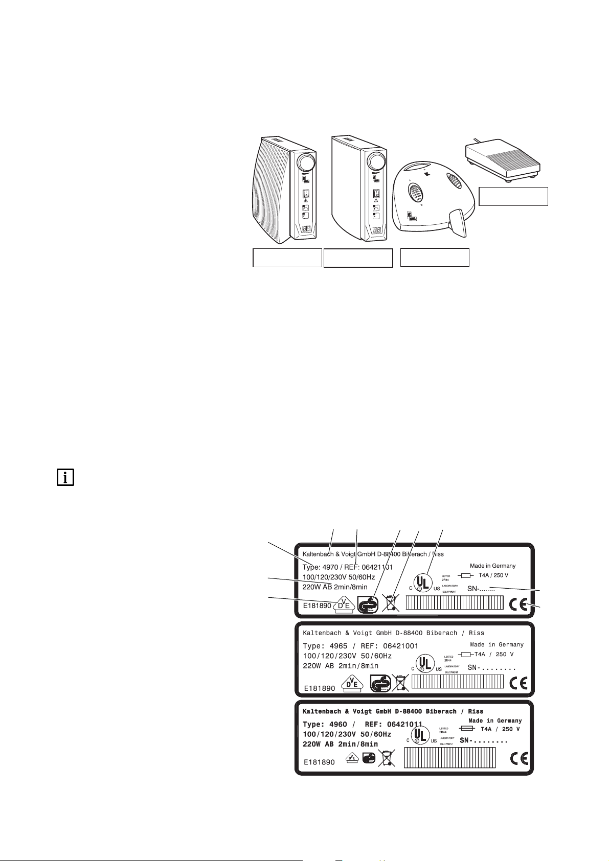
Rating plate
Provides information on:
@ Manufacturer
2 Order number (REF number)
3 GS-Mark
4 For information about proper disposal,
see A1.2
5 CSA-Mark
6 Year of manufacture - Serial number
7 CE-Mark according to 89/336 EWG
8 VDE-Mark
9 Mode:
intermittent service: 2 min, 8 min pause
0 Unit type
@
4
2
6
0
5
7
8
3
9
x
a
m
l
o
r
t
n
o
c
K
l
ro
t
n
o
K
l
o
tr
n
co
0
3
x
a
m
n
n
i
m
/
0
0
0
1
x
c
0
3
x
a
m
n
n
i
m
/
0
0
0
1
x
0
3
/m
0
0
0
n
i
4620
4960
4965
4970
Page 6
K- Control 4960, 4965, 4970.
4
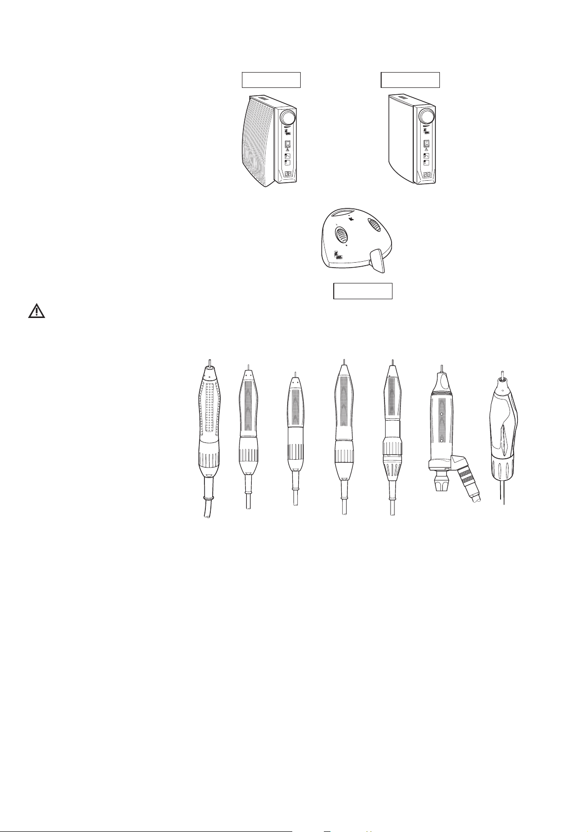
A 1.6 Combination Controller - handpiece
In the combination with K-Control control
units of types 4960, 4965 and 4970, the
following handpieces can be operated:
K 5 Handpiece 4910
K 9 Handpiece 950/955
K 9 Handpiece 4930
K 9 Compact motor 970
K 9 Cutter spindle 960
K 10 Handpiece 4950
(with Adapter 0.674.4721)
K 11 Handpiece 4990
K 12 Handpiece 4940
SF Handpiece 4005
(with supply cable 0.674.4921)
K-POWERgrip 4941
K-ERGOgrip 4944
The safty of the K-Control control
units with handpieces can be
guaranteed only with the handpiece/control
unit combinations approved by KaVo.
4960
4965
K
l
o
tr
n
o
K
l
o
r
t
n
o
c
0
3
x
a
m
n
n
i
m
/
0
0
0
1
x
max
l
o
r
t
n
o
c
in
/m
0
0
0
0
3
c
0
3
x
ma
n
x1000/min
4970
-POWERgrip K12 K5 K11 K9 SF K-ERGOgrip
Page 7
K- Control 4960, 4965, 4970.
5
A 2 Scope of delivery/Accessories
K-Control Knee-operated control unit 4960
or
K-Control Benchtop, control unit 4965
optional
Foot switch 4620
Mat.-No. 0.223.2085
or
K-Control Foot control unit 4970
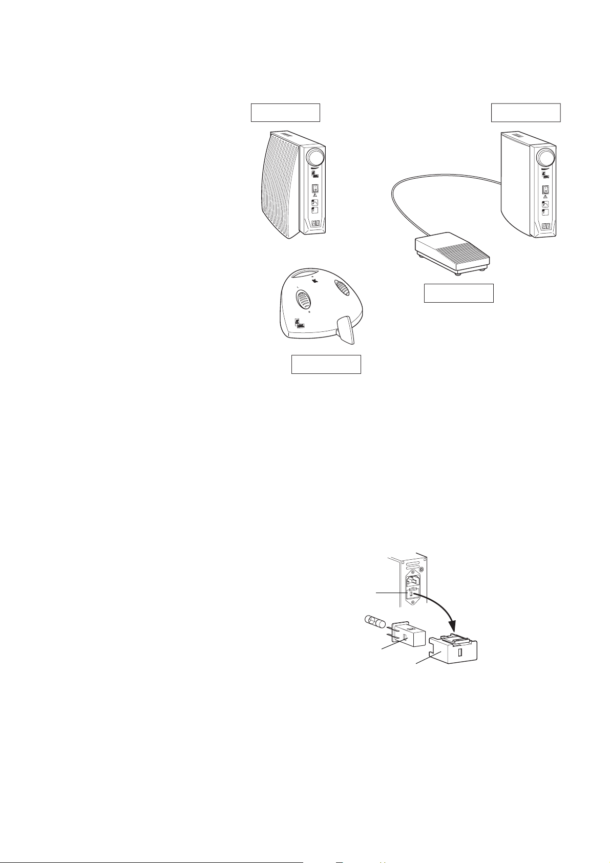
A 3 Electrical connection
Electrical connection
Check that the local mains voltage and
mains frequency conincide with the specifications on the rating plate and the fuse
holder @. Adapt if required.
Voltage adaptation to 100 V/120 V or
230 V.
By removing the fuse holder @, the sleeve
2 with contacts (including fuses) can be
removed. The adaptation is achieved by
appropriately rotating the sleeve ” until
the required voltage, 100 V/120 V or 230 V,
appears in the inspection window of fuse
holder @.
Connected load.
Nominal power max. 220 W.
Disconnection:
Use mains plug as disconnection.
@
2
3
0
1
2
0
1
0
0
4960
0
3
n
m
a
x
x
1
0
0
0
/
m
i
n
K
c
o
n
t
r
o
l
4965
4620
0
3
n
m
a
x
x10
0
0
/
m
i
n
K
co
n
tro
l
4970
c
o
n
t
r
o
l
3
0
0
0
0
/
m
i
n
m
a
x
”
@
Page 8
6
K- Control 4960, 4965, 4970.
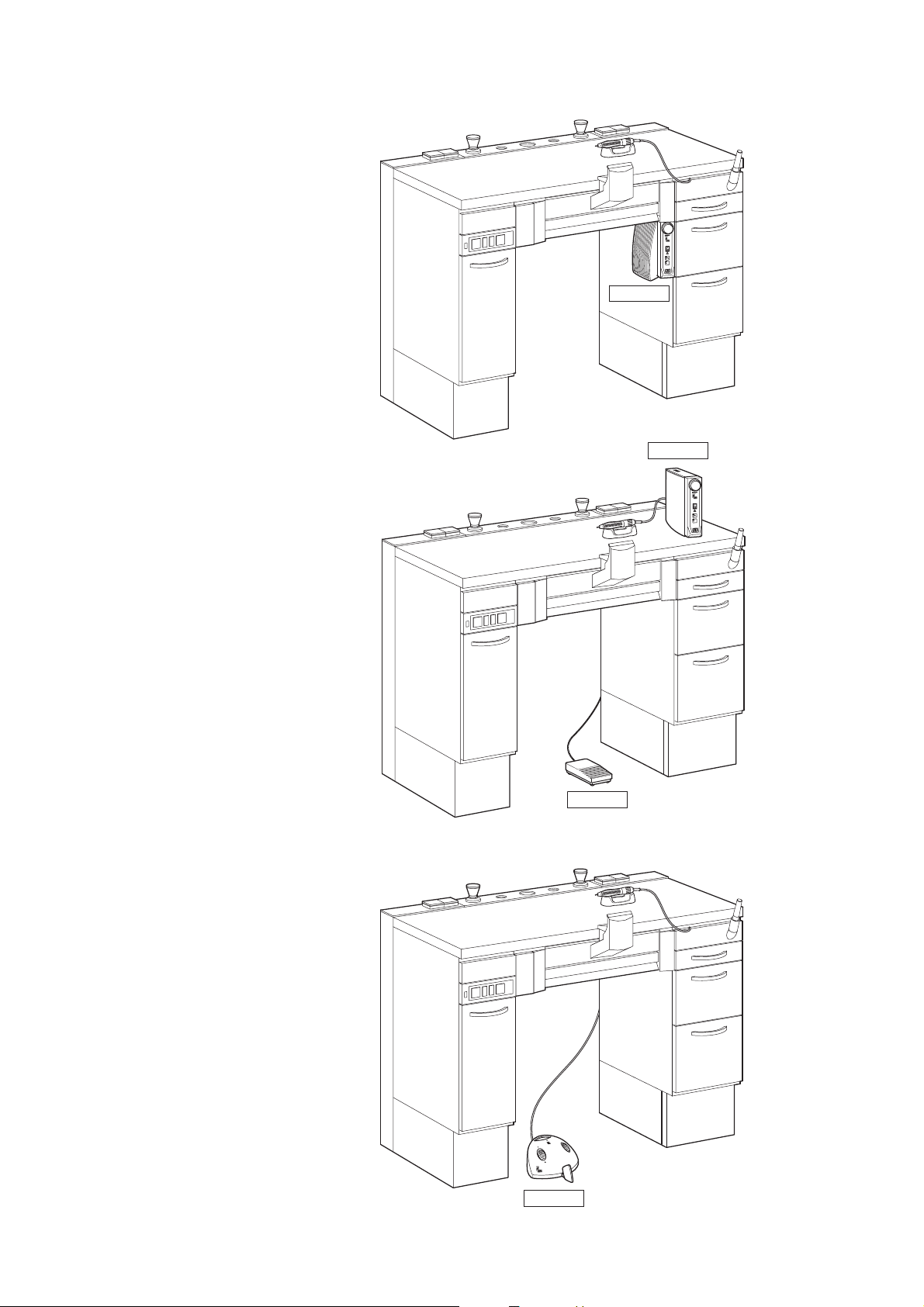
A 4 Location
The K-Control Knee control unit, type
4960, is made to be attached to the side of
a storage cabinet (A 5.1).
The K-Control Benchtop control unit, type
4965, is made to be set on a workbench
and connected underbench with Foot
switch type 4620 (A 5.2).
The K-Control Foot control unit, type
4970, can be set unsecured on the floor (A
5.2).
4960
0
3
n
m
a
x
x
1
0
0
0
/
m
i
n
K
c
o
n
t
r
o
l
4965
0
3
n
m
a
x
x
1
0
0
0
/
m
i
n
K
c
o
n
t
r
o
l
4620
4970
c
o
n
t
r
o
l
3
0
0
0
0
/
m
i
n
m
a
x
Page 9

7
K- Control 4960, 4965, 4970.
A 5 Mounting and connection
A 5.1 Mounting 4960
The K-Control Knee control unit, type
4960, is made to be fastened to the side of
a storage cabinet on a suspenslon
rail 1 (drilling template see page 20).
Fix in place at the front with screws
and insert mains plug into a grounded mains socket which is easy to reach.
(Similarly if using an extension line)
Demounting
page 20
12mm
Ø2,3
Ø3,5
l
tro
n
o
c
K
1
0
3
x
a
m
n
n
i
m
/
0
0
0
1
x
l
tro
n
o
c
K
0
3
x
a
m
n
n
i
m
/
0
0
0
1
x
Page 10

K- Control 4960, 4965, 4970.
8
A 5.2 Mounting 4965 / 4970
Set K-Control Benchtop control unit, type
4965 on a workbench
Set K-Control Foot control unit, type 4970,
on the floor under a workbench.
Fix in place at the front with screw
and insert mains plug into a
grounded mains socket which is easy to
reach. (Similarly if using an extension line)
A 5.3 Connection
Plug in Handpiece and foot switch and
screw finger tight.
Plug in Handpiece and screw finger tight.
control
4965
K
l
tro
n
o
c
0
3
x
a
m
n
n
i
m
/
0
0
0
1
x
x
a
m
n
i
m
/
0
0
0
0
3
4970
4965
4960
4970
Page 11

K- Control 4960, 4965, 4970.
9
A 6 Controls and functional elements
1 Digital speed and malfunction indicator
2 Speed limitation preselector
3 Direction switch (counterclockwise
running limited to max. 5000 min-1)
4 Mains switch "0"/"1"
5 Knee switch
6 Speed preselector (continuous)
7 Suspension rail
8 Fuse holder with voltage adjustment
9 Motor sockets (4-pole)
¯ Starter socket (5-pole)
(Foot switch)
» Foot switch Type 4620
w Foot lever
‰ Control cable jack (connection to the
dust extractor)
0
3
n
m
ax
x
10
0
0
/
m
i
n
K
co
n
tro
l
0
3
n
m
ax
x1
0
0
0
/
m
i
n
K
c
o
n
tro
l
c
o
n
t
r
o
l
3
0
0
0
0
/
m
i
n
m
a
x
#
»
„
@
”
#
£
fi
Ì
\
|
·
¯
@
”
#
£
Ì
@
”
|
·
‰
Page 12

10
A 7 Preparations for commencing
operation
On K-Control control units 4960 and 4965,
push mains switch £ to the "0" OFF position.
Switch the K-Control Foot control unit,
type 4970, to "0" OFF by letting back the
foot lever. Set sliding switch 2 or button
2 for speed limitation to “max. 30,000
min
-1
“.
Set direction switch # to “clockwise“
(yellow LED does not light up) or “R“.
For “counterclockwise“, the handpiece
speed is limited to about 5000 min
-1
.
Do not operate or lay down your
Motorhandpiece, unless an instrument or the test pin is clamped in the
chuck. When the chuck is open, Handpiece
is locked, and inadvertent use will cause
the K-Control control unit to switch to
malfunction. Malfunction indicator
1
lights up or begins to flash.
K- Control 4960, 4965, 4970.
0
3
n
m
a
x
x1
0
0
0
/
m
i
n
K
c
o
n
tro
l
0
3
n
m
a
x
x
1
0
0
0
/m
i
n
K
c
o
n
tr
o
l
c
o
n
t
r
o
l
3
0
0
0
0
/
m
i
n
m
a
x
#
@
”
@
”
#
£
£
#
”
@
Page 13

11
K- Control 4960, 4965, 4970.
A 8 Operation
Check set speed each time before
switching on.
Regulations for prevention of accidents are
to be observed!
When preselecting a speed over 30,000 min
-1
,
button
2
should be pressed (yellow LED
lights up). This additional “enabling“
serves for consciously registering the high
speed and the resultant possible danger
when using tools which may be unsuitable.
A 8.1 Starting K-Control knee control unit 4960
Preselect desired maximum speed on speed
limiter 2.
When the knee switch plate is pressed in
the direction of the arrow the speed can be
continuously regulated from 1000 min
-1
to
the preselected maximum speed.
A 8.2 Starting K-Control Benchtop
Control unit 4965.
Preselect desired maximum speed on speed
limiter 2.
Start your Handpiece at the preselected
speed by depressing Foot switch 4620 q.
A 8.3 Starting a K-Control installation with the type 4970 Foot control
unit.
By pressing the foot control lever in the
direction of the arrow, the speed of the
Handpiece can be regulated (enabled by
sliding switch 2).
Allowing the foot lever | to return under
spring pressure all the way back, stops the
Handpiece.
»
Ì
”
”
”
|
4960
K
l
o
r
nt
o
c
0
3
x
a
m
n
n
i
m
/
0
0
0
1
x
K
l
o
r
t
on
c
0
3
x
a
m
n
n
i
/m
0
0
0
1
x
4620
4965
K
l
o
r
t
n
o
c
0
3
x
a
m
n
n
i
m
/
0
0
0
1
x
K
trol
con
0
3
x
a
m
n
n
i
m
/
x1000
4970
ax
m
l
o
r
t
n
o
c
n
i
30000/m
x
a
m
l
o
r
t
n
o
c
n
i
m
/
0
0
0
0
3
Page 14

12
K- Control 4960, 4965, 4970.
A 9 Operating faults
Repairs and servicing work on the
electrical part of this equipment must
only be undertaken by experts or by persons trained in our factory who are aware
of the safety regulations. Disconnect the
mains plug from the power supply, resp.
switch off the disconnecting switch before
carrying out any maintenance work.
In K-Control knee and table-top con-
trol units, error messages are shown
visually on the display
1
. In the KControl foot control unit, error messages
are indicated by flashing of the malfunction
LED
2
(e.g. error message No. 7 = 7 x
flashes, etc.).
C • Main processor not running
R • Repair or replace motor electronics
C • Overloading of motor, motor current
above 4 A for 7 sec
R • Reduce motor load or stop and re-start
with foot switch.
C • Handpiece blocked for more than 3
seconds
R • Eliminate blocking, stop and restart
C • No handpiece connected (also open
circuit K9, K10)
R • Connect handpiece and restart
C • No handpiece connected (also open
circuit K5, K11, K12, SF)
R • Connect handpiece and restart
C • Handpiece speed too high for longer
than 2 seconds, a phase of the
handpichas been interrupted or
electronics are faulty.
R • Repair handpiece or control unit
F = Fault C = Cause R = Rectificatio
F • Error display: F 6
F • Error display: F 4
F • Error display: F 3
F • Error display: F 2
F • Error display: F 1
F • Error display: F 0
4620
4965
0
3
n
m
ax
x
10
0
0
/
m
i
n
K
co
n
t
r
o
l
0
3
n
m
a
x
x
1
0
0
0
/m
i
n
K
c
o
n
tr
o
l
4960
c
o
n
t
r
o
l
3
0
0
0
0
/
m
i
n
m
a
x
4970
K12 K5 K11 K9 SF
@
@
”
Page 15

K- Control 4960, 4965, 4970.
13
C • Open circuit in speed potentiometer
R • Replace speed potentiometer with
cable
C • Magnets (Knee switch, Foot lever)
inserted twisted
R • Insert magnets correct
C • Fault in hall-effect element
R • For 3 seconds after switching the device
on, a self -diagnosis program is automatically activated.
R • Repair control unit
C • Short-circuit in D.C. chopper transistor
R • Remedy: Repair control unit
C • Measuring device for motor voltage is
faulty
R • Repair control unit
C • Cooling attachment too hot (>90°)
R • Repair control unit
C • Temperature sensor on cooling
R • Repair control unit (short-circuit)
C • Data loss in EEPROM
R • Repair or recalibration of the
control unit
F = Fault C = Cause R = Rectification
F• Error display: F 19
F• Error display: F 18
F • Error display: F 17
F • Error display: F 14
F • Error display: F 13
F • Error display: F 11
F • Error display: F 10
F • Error display: F 9
4620
4965
0
3
n
m
ax
x
10
0
0
/
m
i
n
K
co
n
t
r
ol
0
3
n
m
a
x
x
1
0
0
0
/
m
i
n
K
co
n
t
r
o
l
4960
c
o
n
t
r
o
l
3
0
0
0
0
/
m
i
n
m
ax
4970
K12 K5 K11 K9 SF
Page 16

K- Control 4960, 4965, 4970.
14
Guarantee provisions
For the product cited in the transfer protocol, KaVo warrantees the end customer that the product will function properly, have no material
or manufacturing flaws for 12 months from the date of purchase under the following conditions:
In the case of valid complaints due to defects or a short delivery, KaVo will make good its warranty by replacing the product free of cost or
repairing it according to your wishes. All other claims of any kind are excluded, especially claims for damages.
In case of delayed performance, gross negligence or criminal intent, this shall apply only if there are no compelling legal regulations to the
contrary. KaVo is not liable for defects and their consequences that arise from natural wear, improper cleaning or servicing, the nonobservance of instructions for use, servicing or connection, scale formation or corrosion, impurities in the air and water supply,
or chemical or electrical influences that are unusual or impermissible according to the manufacturer's specifications.
The warranty does not generally extend to lamps, glassware, rubber parts and the colour fastness of plastic parts.
No liability is assumed when defects or their consequences can arise from manipulations or changes to the product by the customer or a
third party.
Claims from this warranty can only be asserted when the transfer protocol (copy) belonging to the product has been sent to KaVo, and the
original can be presented by the operator or user.
Page 17

15
K- Control 4960, 4965, 4970.
4960
2
3
0
1
2
0
1
0
0
0
3
n
m
a
x
x
1
0
0
0
/
m
i
n
K
c
o
n
t
r
o
l
0.642.0561
0.642.0252
0.221.9116
0.642.0272
0.245.5015
0.200.6529
0.200.6528
0.260.9677
0.642.0282
0.692.9051
0.223.2735
0.642.0661
0.692.9031
0.692.9041
0.692.9021
0.696.0221
AT 1.002.6852
0.642.0561
0.696.0311
0.201.7065
0.221.4909
0.242.4012
0.260.8505
0.224.2498
0.223.4142 DE
0.692.6881 CH
0.692.6891 USA/JP
0.692.6901 GB
0.692.6851 AUS
0.223.0050
0.223.2801
F 6,3A 250V
Page 18

16
K- Control 4960, 4965, 4970.
4965
0.245.5015
0.223.0050
0.223.2735
0.642.0561
0.642.0661
0.200.6529
0.200.6528
0.642.0272
0.617.0511
0.692.9051
0.617.0460 1,8 m
0.617.0410 1,0 m
0.224.7001
F 6,3A 250V
0.223.2801
0.223.2085
0.223.2111
0.692.9021
0.220.0423
0.696.0221
AT 1.002.6852
0.642.0561
0.223.4142 DE
0.692.6881 CH
0.692.6891 USA/JP
0.692.6901 GB
0.692.6851 AUS
0.692.9031
0.692.9041
0.221.4909
0.224.2498
0.696.0311
0.242.4012
0.260.8505
0.201.7065
Page 19

17
K- Control 4960, 4965, 4970.
4970
0.642.0572
0.642.0572
0.221.9110
n
i
m
/
0
0
0
0
3
0.642.0582
0.642.0641
0.642.0582
0.223.2059
F 6,3A 250V
0.223.2801
0.221.4909
0.220.0443
0.223.0050
0.251.4545
0.641.7642
0.223.2735 T 4.0A
0.642.0661
0.696.0221
AT 1.002.6852
0.223.4101 DE
0.223.4110 CH
0.223.4127 USA/JP
0.691.8101 GB
0.691.8091 AUS
0.201.7127
0.258.6010
0.221.9116
4x 0.260.9654
0.642.0562
Page 20

18
K- Control 4960, 4965, 4970.
Page 21

19
K- Control 4960, 4965, 4970.
Page 22

20
K- Control 4960, 4965, 4970.
156,5 mm
53 mm MASTERspace
51mm FLEXspace
Ø2,3 mmØ2,3 mm
90 mm MASTERspace
93 mm FLEXspace
Drilling template
Page 23

Page 24

1.000.4575
"
Fk
"
11/07
"
en
"
01.26
KaVo Dental GmbH. D-88400 Biberach/Riss
Telefon +49 7351 56-0 Fax +49 7351 56-1488
Internet: www.kavo.com
 Loading...