

Page 1
Instructions for use
KaVo Dig eXam 3520, 3530
Always be on the safe side.
Page 2

Sales:
KaVo Dental GmbH
Bismarckring 39
D-88400 Biberach
Tel. +49 7351 56-0
Fax +49 7351 56-1488
Manufacturer:
Kaltenbach & Voigt GmbH
Bismarckring 39
D-88400 Biberach
www.kavo.com
Page 3

Instructions for use KaVo Dig eXam 3520, 3530
Contents
Contents
Contents ...........................................................................................................................................................1
1 User notes .....................................................................................................................................................3
1.1 Intended users ......................................................................................................................................... 3
1.2 User guidelines ........................................................................................................................................ 4
1.2.1 Standard documentation ..................................................................................................................4
1.2.2 Abbreviations ...................................................................................................................................4
1.2.3 Symbols used ...................................................................................................................................5
1.2.4 Symbols on nameplates ................................................................................................................... 5
1.3 Service ..................................................................................................................................................... 6
1.4 Implied warranty ....................................................................................................................................... 7
1.5 Limitation of implied warranty ..................................................................................................................8
1.6 Transportation and storage ......................................................................................................................9
1.6.1 Transportation damage ....................................................................................................................9
1.6.2 Information on the packaging: Storage and transport ......................................................................9
2 Safety ..........................................................................................................................................................11
2.1 Explanation of safety symbols ...............................................................................................................11
2.1.1 Hazard warning symbol ..................................................................................................................11
2.1.2 Explanation of different levels of hazard ........................................................................................11
2.1.3 Structure .........................................................................................................................................11
2.2 Intended purpose ................................................................................................................................... 12
2.2.1 General ..........................................................................................................................................12
2.2.2 Product-specific ..............................................................................................................................12
2.3 Safety symbols ....................................................................................................................................... 14
2.4 Prerequisite for proper technical operation ............................................................................................ 16
2.4.1 Data backup ...................................................................................................................................16
2.4.2 Sensor handling .............................................................................................................................17
2.4.3 Standards for IT-components .........................................................................................................18
2.4.4 Standard conformity .......................................................................................................................18
3 Product description ...................................................................................................................................... 20
3.1 Entire system ......................................................................................................................................... 20
3.2 Where to affix the nameplates, power rating plates and caution labels .................................................21
3.2.1 Labeling ..........................................................................................................................................21
3.2.2 Symbols on identification labels .....................................................................................................23
3.3 Sensors ..................................................................................................................................................24
3.3.1 Installation sizes .............................................................................................................................24
3.3.2 KaVo Trigger ..................................................................................................................................25
3.3.3 Data connection via USB 2.0 .........................................................................................................25
3.3.4 Portability of KaVo Dig eXam ......................................................................................................... 26
3.3.5 Holder system for sensor ...............................................................................................................26
3.4 Integration in KaVo In eXam .................................................................................................................. 27
3.4.1 Attaching sensors to KaVo In eXam ..............................................................................................27
3.4.2 Internal USB connection in the scissor arm ...................................................................................28
3.5 Sensor holder ......................................................................................................................................... 29
3.5.1 Active Sensor holder ......................................................................................................................29
3.6 Status icon and sensor status on the PC ...............................................................................................31
1/60
Page 4

Instructions for use KaVo Dig eXam 3520, 3530
Contents
3.7 Technical Data ....................................................................................................................................... 33
3.7.1 KaVo Dig eXam Sensors and Interface .........................................................................................33
3.7.2 IT component requirements ...........................................................................................................33
3.7.3 Ambient conditions for KaVo Dig eXam sensors and interface [compliant with IEC601-1] ............34
3.7.4 Equipment classification .................................................................................................................34
3.7.5 Conformity with standards ..............................................................................................................34
3.7.6 Electrical connection ......................................................................................................................35
3.7.7 Dimensions, mass (original packaging) .........................................................................................35
3.7.8 Exposure times ..............................................................................................................................35
3.7.9 Information on electromagnetic compatibility .................................................................................36
3.8 Dig eXam inspection service (only available in Germany) .....................................................................39
4 Operation ..................................................................................................................................................... 40
4.1 Configuration of the Dig eXam driver software ...................................................................................... 40
4.1.1 Selection Information .....................................................................................................................40
4.1.2 Selection configuration ................................................................................................................... 41
4.1.3 Selection parameters .....................................................................................................................43
4.2 Taking a digital X-ray ............................................................................................................................. 44
4.2.1 Overview ........................................................................................................................................44
4.2.2 Activate programme and select patient .......................................................................................... 44
4.2.3 Prepare and position sensor ..........................................................................................................45
4.2.4 X-ray ...............................................................................................................................................47
4.2.5 Conclude X-ray procedure .............................................................................................................49
4.2.6 Create a diagnosis based on the radiograph .................................................................................49
5 Maintenance/safety inspections ..................................................................................................................50
5.1 Checks ................................................................................................................................................... 50
6 Preparation methods DIN EN ISO 17664 .................................................................................................... 51
6.1 Cleaning and disinfecting .......................................................................................................................51
6.1.1 Cleaning .........................................................................................................................................51
6.1.2 Disinfection .....................................................................................................................................51
7 Accessories and compatibility .....................................................................................................................53
7.1 eXam Family .......................................................................................................................................... 53
7.2 Compatibility ..........................................................................................................................................57
7.2.1 Non-KaVo X-ray machines .............................................................................................................57
7.2.2 IT components ...............................................................................................................................57
8 Troubleshooting ........................................................................................................................................... 58
8.1 Symptoms, causes and solution ............................................................................................................ 59
2/60
Page 5

Instructions for use KaVo Dig eXam 3520, 3530
1 User notes | 1.1 Intended users
1 User notes
1.1 Intended users
This document is intended for use by dentists and other practice or clinic employees
who are conversant with the taking, processing and archiving of computer-based
intraoral X-rays on the Microsoft® Windows operating system .
Prior to using the equipment, it assumed that users have been instructed in the use
of KaVo Dig eXam-Sensors in accordance with the stipulations of the country in
which they are practising, on the safe and proper use of X-ray radiation for the taking
of intraoral dental X-rays.
3/60
Page 6
Instructions for use KaVo Dig eXam 3520, 3530
1 User notes | 1.2 User guidelines
1.2 User guidelines
Requirement
Read these instructions before the initial startup to prevent misuse and damage.
This document has been translated from the German original.
Note
Microsoft and Windows are registered trademarks of Microsoft Corporation and its
registered subsidiaries.
VixWin PRO is a registered trademark of Gendex Dental Systems.
XCP-DS is a registered trademark of DENTSPLY RINN.
KaVo Dig eXam is a protected trademark of KaVo.
The utilisation of company logos or trademarks not named here does not indicate
that they are subject to unrestricted use. Every company logo or trademark men‐
tioned here is the sole property of the company mentioned. Brands, names and
prices are given for information purposes only.
1.2.1 Standard documentation
The product-related documentation consists of the following components. You can
order more of these from KaVo, if necessary:
▪ Customer documents
– User instructions
– Assembly instructions
▪ User instructions Software VixWin PRO.
1.2.2 Abbreviations
Abbrevia‐
tion
ALARA "As low as reasonably achievable": The guiding principle behind radiation protection during the
EMC Electromagnetic compatibility
UI User instructions
Hub A central point: a distribution device that makes available a number of USB interfaces.
IEC International Electrotechnical Commission
AI Assembly instructions
SQL "Structured Query Language": Standardised computer language for querying relational databases
SFC Safety checks
SW Software
STI Service Technician's instructions
USB Universal Serial Bus. Standardised means of connecting peripherals to personal computers.
Meaning
taking of X-rays, meaning that radiation doses for both workers and the public are typically kept
lower than their regulatory limits.
4/60
Page 7
Instructions for use KaVo Dig eXam 3520, 3530
1 User notes | 1.2 User guidelines
1.2.3 Symbols used
See the section Safety/Warning Symbol
Important information for users and technicians
Action request
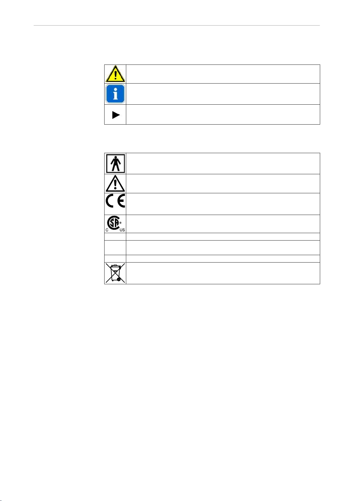
1.2.4 Symbols on nameplates
Type BF application part [5333;IEC 417]
Consult user instructions
CE (Communauté Européenne) mark. Products bearing this mark conform
to the requirements of the pertinent EC directives (applicable European
standards).
CSA label
SN: Serial number
REF: Material number (for sensor size IMat. no. 1.003.4498, for sensor size
IIMat. no. 1.003.4499)
Type: device type (for sensor size I 3520, for sensor size II 3530)
For information about proper disposal, see intended purpose
5/60
Page 8

Instructions for use KaVo Dig eXam 3520, 3530
1 User notes | 1.3 Service
1.3 Service
Service hotline:
+ 49 (0) 7351 56-2900
Service.Roentgen@kavo.com
Please indicate the version number of the program.
Additional information can be obtained at: www.kavo.com
For North America
KaVo Dental
KaVo Technologies / Gendex Imaging
019 West Oakton Street
Des Plaines, IL 60018-1884
USA
+1 (847) 640-48 00
6/60
Page 9

Instructions for use KaVo Dig eXam 3520, 3530
1 User notes | 1.4 Implied warranty
1.4 Implied warranty
The KaVo end-user customer guarantee for the product named in the completion
certificate guarantees that the product functions correctly and that there are no faults
in the material or workmanship for a duration of 12 months following the purchase
date, according to the following conditions:
Following a reasonable complaint relating to defects or short delivery, KaVo will
provide a replacement or perform repairs. KaVo reserves the right to perform re‐
pairs.
Claims of any other nature, damages in particular, are excluded. In case of default
and gross negligence or intent, the latter only applies if there are no compelling legal
provisions opposing it.
KaVo shall not be liable for defects and their consequences, which occur as a result
of normal normal wear and tear, or of improper cleaning and maintenance, nonobservance of the operating, maintenance or connection regulations; calcination or
corrosion; a contaminated air or water supply; or chemical or electrical effects, which
are non-standard or not permitted according to company regulations.
As a general rule, this guarantee does not apply to lamps, glassware, rubber parts
or the colour durability of synthetic materials.
KaVo shall not be liable for defects or their consequences if they are likely to be a
direct result of actions or modifications by a customer or third party.
Any claims arising from this guarantee can only be lodged if the completion certifi‐
cate (carbon copy) has been sent in to KaVo and the operator/user is able to produce
the original.
7/60
Page 10

Instructions for use KaVo Dig eXam 3520, 3530
1 User notes | 1.5 Limitation of implied warranty
1.5 Limitation of implied warranty
KaVo shall assume responsibility for the safety, reliability and performance of all
KaVo system components provided that:
▪ Assembly, upgrades, new settings, modifications or repairs are all carried out
by Service Technicians, who have been trained by KaVo, or by KaVo authorised
dealer personnel
▪ The IT components provided by the operator correspond to the technical hard‐
ware and software requirements included in these user instructions.
▪ The system has been installed and operated in accordance with the User in‐
structions and Assembly instructions.
▪ All servicing is performed in full compliance with DIN VDE-075-1.
▪ In Germany, the location in whichKaVo Dig eXam is installed, must comply with
the regulationsDIN VDE 0100-710: 2002-11 and VDE 0100-560:1995 in its de‐
sign. In other countries, the corresponding national regulations must be respec‐
ted.
▪ The VixWin PRO software has been installed in accordance with the VixWin Pro
user instructions
8/60
Page 11
Instructions for use KaVo Dig eXam 3520, 3530
1 User notes | 1.6 Transportation and storage
1.6 Transportation and storage
1.6.1 Transportation damage
Outside of Germany
Note
KaVo is not liable for damage arising from transportation.
Immediately inspect the delivery after receipt!
If external damage to the packaging is visible upon delivery, follow the procedure
below:
1. The recipient must record the loss or damage in the notice of delivery. The re‐
cipient and employee of the transportation firm must sign the notice of delivery.
The recipient can only assert damages against the transportation company ba‐
sed on these records.
2. Leave the product and packaging unchanged.
3. Do not use the product.
If the product is damaged and there is no discernable damage to the packaging
upon delivery, proceed as follows:
1. Report the damage immediately or at least 7 days after the delivery to the deli‐
very company .
2. Leave the product and packaging unchanged.
3. Do not use a damaged product.
Note
If the recipient does not follow one of the above instructions, the damage will be
held to have occurred after the delivery (according to . CMR law , section 5, Art.
30).
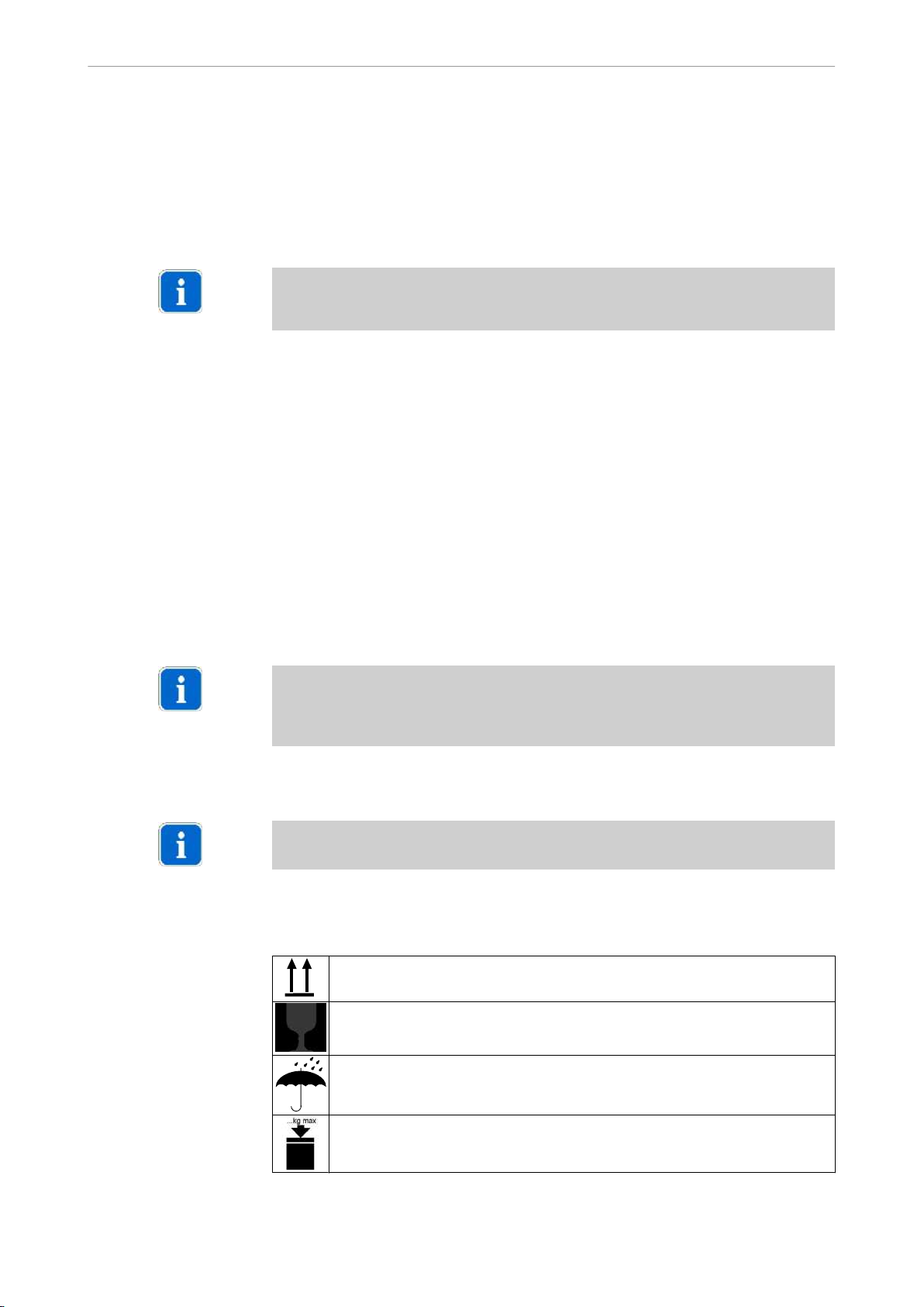
1.6.2 Information on the packaging: Storage and transport
Note
Keep the packaging for returning the product for service or repairs .
The symbols printed on the outside are for transportation and storage, and have the
following meaning:
Transport upright with the arrows pointing upwards
Fragile - protect against knocks
Keep dry
Maximum permitted stacking load
9/60
Page 12
Instructions for use KaVo Dig eXam 3520, 3530
1 User notes | 1.6 Transportation and storage
Temperature range
Humidity
Air pressure
10/60
Page 13
Instructions for use KaVo Dig eXam 3520, 3530
2 Safety | 2.1 Explanation of safety symbols
2 Safety
2.1 Explanation of safety symbols
2.1.1 Hazard warning symbol
Warning symbol
2.1.2 Explanation of different levels of hazard
Safety instructions with three hazard levels are used in this document for avoiding
personal and property damage.
CAUTION
indicates a hazardous situation that can lead to property damage or minor to mo‐
CAUTION
derate injury.
WARNING
DANGER
DANGER
WARNING
indicates a hazardous situation that can lead to serious injury or death.
DANGER
indicates a maximum hazardous situation that can directly cause serious injury or
death.
2.1.3 Structure
The introduction describes the type and source of the hazard.
This section describes the potential consequences of non-observance.
▶ The optional step contains necessary measures for avoiding hazards.
11/60
Page 14
Instructions for use KaVo Dig eXam 3520, 3530
2 Safety | 2.2 Intended purpose
2.2 Intended purpose
2.2.1 General
This KaVo product is intended only for use in the field of dentistry. It is impermissible
to use the product for a purpose for which it was not intended.
"Proper use" includes following all the instructions for use and ensuring that all in‐
spections and service tasks are performed.
Apply and meet the overarching guidelines and/or national laws, national regulati‐
ons and the rules of technology for medical devices applicable for startup and use
of the KaVo product for the intended purpose.
The user must ensure that that the device works properly and is in a satisfactory
condition before each use.
During use, national legal regulations must be observed, in particular:
▪ the applicable health and safety regulations.
▪ the applicable accident prevention regulations.
The user must observe the following:
▪ - only use properly operating equipment.
▪ protect himself or herself and third parties from danger.
▪ avoid contamination from the product.
The safety checks (SFC) must be performed on an annual basis.
Note
The product must be cleaned and serviced according to instructions if it is not to
be used for a long period.
Observe the corresponding country-specific regulations when finally shutting down
a KaVo product. Please direct all questions regarding the proper disposal of KaVo
products to the nearest KaVo branch.
2.2.2 Product-specific
Dig eXamtogether with VixWin PRO is intended for processing dental, intraoral Xrays.
The radiographs are displayed and archived using the software VixWin PRO.
Prior to using the equipment, users of the KaVo Dig eXam-Sensors must have un‐
dergone full instruction, in accordance with the stipulations of the country in which
they are practising, on the safe and proper use of X-ray radiation for the taking of
intraoral dental X-rays.
KaVo Dig eXam has electronic components in the Trigger and Sensor that are to
be disposed of in accordance with the relevant country specific regulations.
12/60
Page 15

Instructions for use KaVo Dig eXam 3520, 3530
2 Safety | 2.2 Intended purpose
Disposal of electronics
Note
According to the EC Directive 2002/96 concerning electrical and electronic used
devices, this product is subject to the cited directive and must be disposed accor‐
dingly within Europe.
Before disassembling and disposing of the product, it must be completely proces‐
sed (disinfected, sterilised) according to the section "Preparation methods".
Additional information can be obtained from KaVo (www.kavo.com) or your dental
supplier.
13/60
Page 16
Instructions for use KaVo Dig eXam 3520, 3530
2 Safety | 2.3 Safety symbols
2.3 Safety symbols
Ionising radiation
Overexposure to X-ray radiation.
CAUTION
CAUTION
CAUTION
▶ The handler can and must take measures, in accordance with country-specific
legal stipulations, to minimise their personal dose of radiation!
Risk of injury by using unsuitable electrical devices.
Increased risks within patient surroundings; e.g. sensing electrical current or re‐
ceiving electric shock through contact with parts
▶ Adhere to the requirements described within these user instructions
▶ Only use IT components that are fully compliant with the requirements descri‐
bed within these user instructions.
▶ If any of the system components are damaged, stop use immediately.
▶ Only use standard-compliant devices.
Injury caused by damaged sensors
Damaged sensors may cause personal injury.
▶ If sensors are damaged, stop using them.
▶ If the sensor wire is damaged, stop using it.
CAUTION
CAUTION
CAUTION
CAUTION
Ignition of ignitable mixtures due to electrical equipment in operation
Deflagration
▶ KaVo Dig eXam must not be operated when using ignitable mixtures.
Malfunctions from electromagnetic fields.
The product meets the applicable requirements regarding electromagnetic fields.
Given the complex interactions between equipment and cell phones, the product
may be influenced by a cell phone that is in use.
▶ Do not use cell phones in medical offices, hospitals, or laboratories.
▶ Turn off electronic devices such as computer storage media, hearing aids, etc.
during operation .
Risks from electromagnetic fields.
The functions of implanted systems (such as pacemakers) can be influenced by
electromagnetic fields.
▶ Ask patients before treatment.
Loss of data when taking x-rays
When the transmission of data from the KaVo Dig eXam sensor to the computer
does not meet the USB 2.0 standard, data may be lost when taking x-rays due to
the limited bandwidth of earlier USB versions.
▶ Each USB connection between the computer and sensor must completely meet
the USB 2.0 standard.
▶ Each port (computer or hub) to which the sensors are connected must offer the
full output of 500 mA specified fur USB.
▶ The operating system for the computer must support USB 2.0 in high-speed
mode. The most recent service pack by Microsoft must be installed.
▶ The protective conductor connections described in these instructions must be
installed.
14/60
Page 17

Instructions for use KaVo Dig eXam 3520, 3530
2 Safety | 2.3 Safety symbols
Monitor image interference preventing accurate diagnosis
The quality of the X-ray image displayed on screen is dependent both on the prac‐
CAUTION
tice or clinic's ambient conditions as well as the monitor settings.
▶ If you suspect interference on the image display, use test images to check
whether the problem lies with the monitor.
▶ Clean the screen on a regular basis.
▶ Make sure that you use correct screen settings only.
Note
When positioning the screen, keep it out of direct sunlight and prevent light reflec‐
ting off it to enable the medical data to be read properly.
15/60
Page 18
Instructions for use KaVo Dig eXam 3520, 3530
2 Safety | 2.4 Prerequisite for proper technical operation
2.4 Prerequisite for proper technical operation
Responsibility is assumed for the safety, reliability and performance of the compo‐
nent supplied by KaVo when:
▪ Installation, expansions, adjustments, changes or repairs is done by technicians
trained by KaVo or third parties authorised by KaVo for the Dig eXam, or by the
personnel of authorised distributors.
▪ The unit is operated according to the instructions for use and installation.
▪ The IT components supplied by the operator meet the technical requirements in
these instruction for use for hardware and software, and they are installed and
set up according to the descriptions of these components.
▪ KaVo Dig eXam is an electronic medical device, and is subject to the special
precautions necessary for EMC. KaVo Dig eXam may only be operated when it
has been installed according to the EMC instructions in the instructions for use
and installation.
▪ When setting up the unit, follow all the requirements of VDE 0751-1, "Repeated
tests and test before startup of electronic medical devices and systems - general
guidelines".
▪ In Germany ,the room in which the Dig eXam is installed must be designed ac‐
cording to the specifications DIN VDE 0100-710:2002-11 ad VDE
0100-560:1995. In other countries, follow the corresponding national specifica‐
tions.
CAUTION
Note
The installation and fitting of IT components for Dig eXam are the responsibility of
the practice or clinic.
Unauthorised accessories
Only original replacement parts and accessories should be used, to ensure that
there is no increase in the emissions and/or a reduction in the stability in terms of
the electromagnetic compatibility.
▶ Only use authorised or recommended spare parts and accessories.
See also: 3.7 Technical Data, Page 33
Observe the corresponding country-specific regulations when finally shutting down
a KaVo product. Please direct all questions regarding the proper disposal of KaVo
products to the nearest KaVo branch.
See also: Technical data in user instructions.
2.4.1 Data backup
It is the user's responsibility alone to back up data.
KaVo recommends daily back-up.
16/60
Page 19
Instructions for use KaVo Dig eXam 3520, 3530
2 Safety | 2.4 Prerequisite for proper technical operation
Data loss
Establish a data backup strategy.
CAUTION
▶ VixWin PROuses the file system supplied with the Microsoft operating system
for saving image data. Correspondingly, this data must also be included within
the backup strategy of your practice or clinic.
Note
The image data produced using KaVo Dig eXam replaces the conventional intraoral
radiographs taken on X-ray film and, as such, is subject to the same country-spe‐
cific requirements governing this; such as the mandatory length of time for storing
X-rays etc.
These country-specific stipulations and requirements may also include the recor‐
ding of dosage levels and information about the patient's indication.
The user should regularly make back-up copies If a hard disk in the PC fails, this
protects from data loss and increases the safety of the system data. Such a copy is
also termed a backup. It should not be confused with the export of data in which the
data remain in the PC.
Store backup copies in a safe place.
There are various backup options. You can choose between:
▪ A full backup, which always backs up every single piece of data on the hard drive
that needs backing up.
▪ An incremental backup, which only saves data that has been modified since the
last backup.
A full backup is a lengthy procedure and cannot be performed on a daily basis.
Therefore, practices nowadays usually decide to implement a hybrid of the two
backup options (full and incremental). whereby, at one point in time, the entire
quantity of stored data is backed up and, on later occasions, backups are run at
regular intervals for modified data only.
Please also note that a hard drive error may occur whilst a backup is being written.
For this reason, you should never overwrite the most recent backup copy.
Note
The computer expert or system administrator at your practice will have the most
up-to-date technical information as regards keeping and running backup copies.
2.4.2 Sensor handling
Precautionary instructions for handling the sensors
Never:
▪ Sterilise the sensors or subject them to high-pressure sterilisation (autoclave).
▪ Drop the sensors.
▪ Twist or tread on the sensor wires.
▪ Let patients bite on the sensor or its wire.
▪ Remove the sensors when in use or while the X-ray is being taken.
▪ Pull or bend the wire..
▪ Immerse the KaVo trigger in the cleaning bath.
17/60
Page 20

Instructions for use KaVo Dig eXam 3520, 3530
2 Safety | 2.4 Prerequisite for proper technical operation
Electrostatic discharge
▪ When the sensors are not in use, it is recommended that they be stored in the
storage containers provided.
▪ Never touch the USB connection contact points!
2.4.3 Standards for IT-components
The IT components used in conjunction with Dig eXam, in particular USB-connec‐
tion between Dig eXam and the PC must correspond with the details given in these
User instructions.
See also: 2.4.4 Standard conformity, Page 18
See also: 3.3.3 Data connection via USB 2.0, Page 25
2.4.4 Standard conformity
The KaVo Dig eXam Sensors and the KaVo Dig eXam Interface comply with the
following standards
▪ IEC 60601-1:1988 +A1:1991 + A2:1995 [For the USA UL 60601-1:2003. For
Canada CAN/CSA 22.2 N0.: 601-1]
▪ IEC 60601-1-2:2001
The KaVo Dig eXamdriver software conforms to standards:
▪ IEC 60601-1-4: 1996 + A1: 1999
Note
The delivered Vix Win Pro software also meets this standard.
KaVo Dig eXam and the IT components together make up a medical, electrical sys‐
tem.
The standards applicable to these IT components depend on their specific location
within the practice or clinic. In general, these IT components must comply with IEC
60950-1:2001.
The system that is formed by these IT components andKaVo Dig eXam when in‐
stalled in accordance with the assembly instructions for KaVo Dig eXam and meets
the requirements stipulated in this section, conforms to standard
- IEC 60601-1-1:2000
Rooms used for medical purposes
The room where KaVo Dig eXam Sensors are operated, must be designed in ac‐
cordance with regulationDIN VDE 0100-710:2002-11. In other countries, the corre‐
sponding national regulations must be respected.
18/60
Page 21

Instructions for use KaVo Dig eXam 3520, 3530
2 Safety | 2.4 Prerequisite for proper technical operation
patient environment
When the above-mentioned IT components are installed in the patient environment,
the requirements of basic specialist standard IEC 60601-1:1988 +A1:1991 +
A2:1995
defines the surroundings of the patient in accordance with IEC 60601-1-1:2000: „ ...
any volume whereby, intentionally or unintentionally, a connection may be created
between the PATIENT and parts of the SYSTEM or other persons who may come
into contact with parts of the SYSTEM. ... “
Medical system
The requirements of the applicable standards have been met if:
▪ The IT-components on the Dig eXam via USB are installed in the same room
and
▪ One of the following applies:
– The Dig eXam Sensor together with the Dig eXam Interface is connected
(integrated solution in In eXam or in connection with the active sensor holder
of Dig eXam). The IT device can be run in accordance with IEC 60950-1 if
arranged outside of the patient surroundings.
– The IT components are located within the patient environment: The device
on which the Dig eXam is connected directly, fulfills the standard IEC
60601-1.
– The IT components are located outside of the patient environment: The de‐
vice is on which the Dig eXamis directly connected, complies with the
standard IEC 60950-1 and has a second permanently connected equipo‐
tential bonding that complies with IEC 60601-1-1.
Monitors
Note
The dental radiographs created byKaVo Dig eXam are examined and diagnosed
using the dental practice's own image representation device (monitor). There are
country-specific regulations in force governing (regular) check-ups of the greyscale
display for these image representation devices.
In Germany, at least one monitor at the dental practice must be tested for constancy
on a regular basis in accordance with DIN-V 6868-57:2001.
19/60
Page 22

Instructions for use KaVo Dig eXam 3520, 3530
HUB
HUB
HUB
HUB
< 5m
< 5m
1
1
2
3
3 Product description | 3.1 Entire system
3 Product description
3.1 Entire system
The entire KaVo Dig eXam consists of:
- the ① Dig eXam Sensors (comprising detector and trigger, the KaVo Dig eXamInterface (optional), the ② Dig eXam-Driver-Software
- the ③ VixWin PRO-Software
- IT-components
- accessories
KaVo Dig eXam and the VixWin PRO-Software together form a complete system
which can easily be used with non-KaVo X-ray machines.
Used in conjunction with KaVo In eXam and the Dig eXam interface, you have a
fully integrated X-ray system with extra functions.
Dig eXam has two additional software programs for customers in Germany:
1. A tool for supporting the required acceptance and constancy test in Germany.
2. A program for listing the existing images (x-ray folder)
20/60
Page 23

Instructions for use KaVo Dig eXam 3520, 3530
K
a
V
o Dig
e
X
am
1
A
C
B
5
3
2
4
X. XX X. XXX X
XXXXX X
Dig eXam Sensor Size 1
Kaltenbach & V oigt Gmb H
Bismarckring 39
D-88400 Biberach / Riss
!
3520 T ype :
Ref : 1.003.4498
SN :
Manufactored : Month, Y ea r
USB 2.0 max. 500 mA
6
3 Product description | 3.2 Where to affix the nameplates, power rating plates and caution labels
3.2 Where to affix the nameplates, power rating plates and caution
labels
3.2.1 Labeling
① Product name ⑥ Rating plate overview (on packaging)
② Consult user instructions (A) Dot to mark position. This is entered
③ Type BF application part (B) Sensor label (sensor I or sensor II)
④ KaVo Dig eXam sensor rating plate (C) USB symbol on connector
⑤ Label for KaVo Trigger/USB lead
automatically on the radiographs by
KaVo Dig eXam.
21/60
Page 24

Instructions for use KaVo Dig eXam 3520, 3530
3 Product description | 3.2 Where to affix the nameplates, power rating plates and caution labels
Hardware driver for Vix-Win Mat. no. 1.002.8220
① Program version ③ Unambiguous ID
② ID and language edition
Installations CD Vix Win Pro. Mat. no. 1.002.4813
22/60
Page 25

Instructions for use KaVo Dig eXam 3520, 3530
3 Product description | 3.2 Where to affix the nameplates, power rating plates and caution labels
3.2.2 Symbols on identification labels
Type BF application part [5333;IEC 417]
Consult user instructions
CE (Communauté Européenne) mark. Products bearing this mark conform
to the requirements of the pertinent EC directives (applicable European
standards).
CSA label
SN: Serial number
REF: Material number (for sensor size IMat. no. 1.003.4498, for sensor size
IIMat. no. 1.003.4499)
Type: device type (for sensor size I 3520, for sensor size II 3530)
For information about proper disposal, see intended purpose
23/60
Page 26

Instructions for use KaVo Dig eXam 3520, 3530
3 Product description | 3.3 Sensors
3.3 Sensors
3.3.1 Installation sizes
Sensor I (left) and sensor II (right).
The receiver side is marked with a dot that is also shown on the digital X-ray.
24/60
Page 27

Instructions for use KaVo Dig eXam 3520, 3530
3 Product description | 3.3 Sensors
3.3.2 KaVo Trigger
KaVo Trigger
The KaVo trigger connects the X-ray image detector to the computer system via a
USB 2.0 data path. This connection takes place in the X-ray device
KaVo In eXamsimply by inserting the interface in the X-ray head and in the
KaVo Dig eXamfitted in the machine.
When using the Dig eXam sensors with other X-ray machines it is possible to con‐
nect the KaVo Trigger to the so-called "active sensor holder" or alternatively to
connect it directly to the computer using the accessory cable supplied. In this case
a Dig eXAM sensor of one size can be exchanged with a sensor of another size by
changing the trigger.
Note
The accessory line is "Pull/Push“-Connection. It must not be twisted when pulled
out and plugged in.
when changing the Dig eXam Sensor from machine to machine or for another sensor
size, the detector can be laid down in the sensor holder fitted on the KaVo Trigger.
This sensor holder can be removed for cleaning the KaVo Trigger..
When the sensor holder is opened and the detector is removed, a button is acces‐
sible.
This button directly activates the system to take x-rays when the Dig eXam sensor
is not connected to the KaVo In eXam or is being operated in mixed-mode.
See also: 3.4.1 Attaching sensors to KaVo In eXam, Page 27
3.3.3 Data connection via USB 2.0
The sensor is connected to the machine via a USB 2.0 connection. The components
are physically connected to each other via simple plug-fit connections. Anchoring
the KaVo trigger into the device on the X-ray generator establishes the physical
connection between the machine and KaVo trigger or sensors. In accordance with
USB standards, the USB data connection may comprise up to four 5m sections.
Hubs that are compliant with USB 2.0 must be used to connect up the individual
sections
25/60
Page 28

Instructions for use KaVo Dig eXam 3520, 3530
3 Product description | 3.3 Sensors
Every hub that is directly connected to a KaVo sensor, i.e. with
noKaVo Dig eXamInterface, must be capable of supplying the requisite current. As
a rule, this means that a transformer will need to be used (also for laptops if neces‐
sary).
The requirements listed in the chapter "Standard conformity" must be complied with.
See also: 2.4.4 Standard conformity, Page 18
Note
When using 5 metre long USB-cables the the USB-connection must plugged di‐
rectly into the so-called motherboard. Insertion in the USB ports that are within the
PC on further cables, is not permitted.
Note
Passive USB extension cords may not be used. The distances between two HUBs
may only be bridged with a cord 5 m or less.
3.3.4 Portability of KaVo Dig eXam
KaVo Dig eXam is can be transported from one location to another, in order to
enable operation of the sensors in different treatment rooms.
KaVo Dig eXam is thus excellently suited for a multi-user installation in dental clinics
or group practices.
The handy size provides optimum flexibility and offers you independence when
using the sensors on a day-to-day basis.
3.3.5 Holder system for sensor
The positions in which the sensor can be placed in the mouth are the same as those
for classic radiology when using X-ray film.
A colour-coded XCP-DS holding system is supplied as standard to assist in the
positioning of KaVo Dig eXam sensors for the parallel/right-angle technique.
This system includes the following:
▪ Blue holder for the anterior teeth
▪ Yellow holder for the molar area
▪ A red holder for bitewing radiographs
▪ A green holder for endodontic use
Note
The use of the retention system is shown on the poster that comes with the retention
system.
See also:
7 Accessories and compatibility, Page 53
26/60
Page 29

Instructions for use KaVo Dig eXam 3520, 3530
3 Product description | 3.4 Integration in KaVo In eXam
3.4 Integration in KaVo In eXam
3.4.1 Attaching sensors to KaVo In eXam
KaVo Dig eXamSensors are specifically intended to be integrated with
theKaVo In eXam. In this case, the optional USB lead is separated from the KaVo
trigger and the KaVo trigger is inserted directly into the prepared opening at the head
of the X-ray machine. The detector itself is placed in its special holder on the KaVo
trigger, meaning that it is always on hand for use by the dentist.
Position of KaVo Sensors on the device
KaVo Dig eXam then enables the sensor to be removed without switching off the
machine, simply by pulling gently and placing in another room.
Storage in the RWT holder.
A Dig eXam sensor can be stored in the provided RWT holder on the In eXam.
The sensor must have hygienic protection and be inserted in the desired variation
of the RWT holding set.
27/60
Page 30

Instructions for use KaVo Dig eXam 3520, 3530
3 Product description | 3.4 Integration in KaVo In eXam
The prepared RWT holder can be inserted with the guide rod into the provide clip
on the In eXam.
Note
KaVo recommends that this option only be used for temporary storage to prevent
damage from bumps, etc.
3.4.2 Internal USB connection in the scissor arm
If the KaVo trigger is operated in conjunction with a KaVo In eXam machine, it is
connected to the system via a plug-fit connection at the X-ray emitter. This establi‐
shes a USB connection to the machine or to KaVo Dig eXam, enabling the transfer
of data.
Technical background:
KaVo X-ray machines are equipped with an internal USB line that leads directly to
theKaVo Dig eXaminterface in the X-ray machine via the scissor arm.
28/60
Page 31

Instructions for use KaVo Dig eXam 3520, 3530
3 Product description | 3.5 Sensor holder
3.5 Sensor holder
A sensor holder belongs to the Dig eXam.
It is fitted on the wall and is used for holding a sensor between treatments when the
Dig eXam-Sensor is not used together with the KaVo In eXam.
The sensor is held in the holder by a magnet.
The sensor holder can be taken off the KaVo Trigger in this case and laid in the
sensor tray.
3.5.1 Active Sensor holder
With the optionally obtainable Dig eXam interface Mat. no. 1.003.2363 the distance
to the PC or hub can be increased to a max. 5 m line length from the USB 2.0, for
example to place the IT components outside of the patient's environment.
The interface in this case is mounted covered by the plastic part of the sensor holder,
and the accessory line to the KaVo trigger is tightly connected to the arising active
sensor holder.
29/60
Page 32

Instructions for use KaVo Dig eXam 3520, 3530
3 Product description | 3.5 Sensor holder
In addition, it is possible in this case to run the line under the wall surface from the
sensor cover to the IT component.
30/60
Page 33

Instructions for use KaVo Dig eXam 3520, 3530
3 Product description | 3.6 Status icon and sensor status on the PC
3.6 Status icon and sensor status on the PC
Two icons are visible in the Windows system area (cut-out in the so-called taskbar
next to the system clock)
The blue -Icon displays that the software interfaces between Dig eXam-Hard‐
ware and VixWin-Software is loaded.
The colour of the -Icon shows the availability of the Dig eXam-Systems connected.
Note
Other icons can be displayed dependent on the set up of the X-ray system. These
icons refer to further KaVo or Gendex equipment and are described in the relevant
documentation.
Note
This area of the Windows desktop in which the status icons are show is a part of
the so-called windows taskbar. Windows should be configured so that the status
icons are always visible when taking an X-ray. The configuration of the taskbar is
described in Windows Help.
The following is a list of all the possible statuses and their icons
31/60
Page 34

Instructions for use KaVo Dig eXam 3520, 3530
3 Product description | 3.6 Status icon and sensor status on the PC
When the icon is green, the electronics, sensor and connections are operating cor‐
rectly.
The sensor is ready to detect the x-rays.
When the icon is YELLOW, the electronics, sensor and connections are operating
correctly.
The sensor is waiting for the exposure to be activated.
Note
If you are using a system that is not connected to KaVo In eXam, the KaVo trigger
must be used to activate the process and must be pressed before the X-ray is taken.
If you are using a system that is connected to KaVo In eXam, activation occurs
automatically once you start taking the X-ray.
The icon in RED status: Dig eXam is not connected to the PC and/or not ready to
take an X-ray.
32/60
Page 35

Instructions for use KaVo Dig eXam 3520, 3530
3 Product description | 3.7 Technical Data
3.7 Technical Data
3.7.1 KaVo Dig eXam Sensors and Interface
Data connection USB 2.0
Pixel size 18,5 µm / theoretical resolution 27 LP/
Pixel binning 1 x 1
System resolution typ. 18 LP/mm / min 16 LP/mm [at
Active surface sensor size (3520) 30 x 22 mm
Active surface sensor size II(3530) 36 x 27 mm
kV range 60-70 kV
3.7.2 IT component requirements
mm
200µGy, 60kV] > 50 µGy
2
2
Compliance with standards when instal‐
IEC 60601-1:1988 +A1:1991 +A2:1995
ling IT components in patient surroun‐
dings
Compliance with standards when instal‐
IEC 60950-1:2001
ling IT components outside of patient
surroundings and using the Dig eXam
interface to connect the sensor.
Compliance with standards when instal‐
ling IT components outside of patient
IEC 60950-1: 2001 and a second pro‐
tective conductor connection
surroundings and connecting sensor di‐
rectly without using the Dig eXam inter‐
face.
Data interface for sensors USB 2.0, 500 mA, High Speed
Data interface for Dig eXam Interface
100 mA
USB 2.0
(self-powered mode)
Data interface for Dig eXam Interface
500 mA
USB 2.0
(bus-powered mode)
Operating system Windows 2000 or Windows 2003 with
most up-to-date service pack, Windows
XP with most up-to-date service pack
Labelling European CE marking
Connection of IT components to mains
supply
Use of portable multiple sockets is pro‐
hibited.
Note
Further information in theuser instructions VixWin PRO.
33/60
Page 36

Instructions for use KaVo Dig eXam 3520, 3530
3 Product description | 3.7 Technical Data
3.7.3 Ambient conditions for KaVo Dig eXam sensors and interface
[compliant with IEC601-1]
Operation
Air humidity Condensation is not permitted to form on
Air pressure between 700 hPa and 1060 hPa
Ambient temperature 10° to 40° Centigrade
Storage and transport
Air humidity relative Air humidity between 10% and
Air pressure between 700 hPa and 1060 hPa
Unpacked 5° to 70° centigrade
In original packaging -20° to 70° centigrade (short term up to
the machine; relative atmospheric humi‐
dity 30-75%
95% (TBC uwezel)
2h: -40° C to 85° centigrade)
3.7.4 Equipment classification
KaVo Dig eXam Sensors
▪ Class I
– in accordance with EC Directive 93/42/EEC of June 14, 1993
▪ Application part type BF (IEC 601-1)
– Not protected from the penetration of water [IP20].
– Not suitable for sterilisation.
– Suitable for wipe or surface disinfection using the cleansers described in the
instructions for use.
– Not suitable for operation in environments with combustible mixtures.
KaVo active sensor holder
▪ Not protected from the penetration of water [IP20].
▪ Not suitable for sterilisation.
▪ Suitable for wipe or surface disinfection using the cleansers described in the
instructions for use.
▪ Not suitable for operation in environments with combustible mixtures.
3.7.5 Conformity with standards
See also: 2.4.4 Standard conformity, Page 18
34/60
Page 37

Instructions for use KaVo Dig eXam 3520, 3530
3 Product description | 3.7 Technical Data
3.7.6 Electrical connection
KaVo Dig eXam Sensors
DC voltage 5V [supply via USB 2.0]
Max. power 500 mA
Data connection USB 2.0
KaVo active sensor holder
DC voltage 12V ±10 %
Max. current 600 mA
Data connection USB 2.0 interface
Compliance with
power supply standards
Length of feeder < 20 m
Must comply with IEC 60950-1:2001
Note
In Europe, the manufacturer's CE marking on the power supply unit confirms that
relevant power supply standards have been complied with.
3.7.7 Dimensions, mass (original packaging)
Size of packaging approx. 300 x 330 x 220 mm³
Weight < 5 kg
3.7.8 Exposure times
KaVo Dig eXam sensors in conjunction with KaVo In eXam
Preset dose level of 5 (60 kV is recommended) in digital mode.
Note
This recommended dosage is based on thresholds which are applicable for the
Federal Republic of Germany and may need to be adjusted in accordance with
relevant country-specific regulations and/or individual diagnostic circumstances.
See also: User instructions KaVo In eXam.
KaVo Dig eXam sensors in conjunction with non-KaVo intraoral X-ray
equipment
The dose must be preselected according to applicable national regulations (ALARA
principle). The sensor can be operated over a wide dose range corresponding to
ISO film speed class F-20% up to speed class D.
35/60
Page 38

Instructions for use KaVo Dig eXam 3520, 3530
3 Product description | 3.7 Technical Data
KaVo recommends that the sensors be operated at 60kV
3.7.9 Information on electromagnetic compatibility
Guidelines and manufacturer's declaration - electromagnetic emissi‐
ons
In eXam is intended for use in an environment as stipulated below. The customer
or user of In eXam should ensure that it is operated in an environment of this type.
Emissions measurements Conformity Electromagnetic environment - gui‐
de
HF-emissions in accordance within
CISPR 11
HF-emissions in accordance with
CISPR 11
Emissions of harmonic oscillations
in accordance with IEC61000-3-2
Emissions of voltage fluctuations /
flicker in accordance with
IEC61000-3-3
Group 1 Dig eXam uses HF energy solely for
its internal functions. Its HF radiati‐
on is therefore very low, and it is
unlikely that nearby devices will be
subject to interference.
Class B Dig eXam is suitable for use in all
devices, including those used in do‐
mestic environments and similar
which are connected directly to a
public supply grid which also sup‐
plies buildings which are used for
residence purposes.
Class A Dig eXam is suitable for use in all
devices, including those used in do‐
mestic environments and similar
which are connected directly to a
public supply grid which also sup‐
plies buildings which are used for
residence purposes.
Compliant Dig eXam is suitable for use in all
devices, including those used in do‐
mestic environments and similar
which are connected directly to a
public supply grid which also sup‐
plies buildings which are used for
residence purposes.
Stability tests IEC 60601 - Test level Compliance level Electromagnetic environment - gui‐
de
Discharge of static
electricity in accor‐
dance with IEC
61000-4-2
Rapid transient electri‐
cal disturbances / burst
in accordance with IEC
61000-4-4
Surges in accordance
with IEC 61000-4-5
+/- 6 kV Contact di‐
scharge
+/- 8 kV Air discharge
+/- 2 kV +/- 2 kV for
mains cables +/- 1 kV
for input and output ca‐
bles
+/- 1 kV Normal mode
voltage
+/- 2 kV Common mode
voltage
+/- 6 kV Contact di‐
scharge
+/- 8 kV Air discharge
+/- 2 kV for mains ca‐
bles
+/- 1 kV for input and
output cables
+/- 1 kV Common mode
voltage
+/- 2 kV Common mode
voltage
36/60
Floors should be made of wood or
concrete or be covered with cera‐
mic tiles If the floor is covered with
a synthetic material, the relative air
humidity must be at least 30 %.
The quality of the supply voltage
should be equivalent to that of a ty‐
pical business or hospital environ‐
ment.
The quality of the supply voltage
should be equivalent to that of a ty‐
pical business or hospital environ‐
ment.
Page 39

Instructions for use KaVo Dig eXam 3520, 3530
3 Product description | 3.7 Technical Data
Stability tests IEC 60601 - Test level Compliance level Electromagnetic environment - gui‐
de
Voltage drops, shortli‐
ved interruptions und
fluctuations in the sup‐
ply voltage in accor‐
dance with IEC
61000-4-11
< 5 % UT (> 95 % drop
in UT) for 1/2 period)
40 % UT (60 % drop in
UT) for 5 periods,
70 % UT (30 % drop in
UT) for 25 periods,
< 5 % UT (> 95 % drop
in UT) for 1/2 periods
< 5 % UT (> 95 % drop
in UT) for 1/2 period)
40 % UT (60 % drop in
UT) for 5 periods,
70 % UT (30 % drop in
UT) for 25 periods,
< 5 % UT (> 95 % drop
in UT) for 1/2 period)
The quality of the supply voltage
should be equivalent to that of a ty‐
pical business or hospital environ‐
ment. When the user of Dig eXam
demands continuing function of the
device even when the power supply
is interrupted, it is recommended
that Dig eXam be powered via an
uninterruptible power supply or a
battery.
Magnetic field at the
supply frequency
(50/60 Hz) in accor‐
dance with IEC
3 A/m 3 A/m Magnetic fields at the mains fre‐
quency should correspond to the
typical values found in business
and hospital environments.
61000-4-8
Guidelines and manufacturer's declaration - electromagnetic stability
Dig eXam is intended for use in the electromagnetic environment stipulated below.
The customer or user of In eXam should ensure that it is operated in an environment
of this type.
Stability tests IEC 60601 - test level Compliance level Electromagnetic environment - gui‐
de
Directed HF disturban‐
ces in accordance with
IEC 61000-4-6
Directed HF disturban‐
ces in accordance with
IEC 61000-4-3
3 V
eff
150 kHz to 80 MHz
3 V/m
80 MHz to 2.5 GHz
3 V
3 V/m
Portable and mobile radio equip‐
ment should not be used near to In
eXam or its cables, as the recom‐
mended safe distance has been
calculated in accordance with the
equation applicable for the trans‐
mitting frequency.
Recommended safe distance :
P
d = 1,2 *
up to 800 MHz
d = 2,3 * P for 800 MHz to 2.5 GHz
where PA is the power rating of the
transmitter in watts (WA) according
to information from the manufactu‐
rer of the transmitter, and d is the
recommended safe distance in me‐
tes (m).
The field intensity of stationary ra‐
dio transmitters should, at all fre‐
quencies according to local investi‐
gations,a be lower than the
compliance levelB.
Near to devices bearing the symbol
, interference is possible.
Comment:
The higher frequency range is applicable at 80 MHz und 800 MHz.
37/60
Page 40

Instructions for use KaVo Dig eXam 3520, 3530
3 Product description | 3.7 Technical Data
a
The field intensity of stationary transmitters such as the base stations of radio
telephones and mobile land radio devices, amateur radio stations, AM and FM
broadcasting services or television transmitters cannot, in theory, be determined
precisely in advance. To determine the electromagnetic environment in respect of
stationary transmitters, a study of the location should be considered.
If the measured field intensity at the location in which Dig eXam is being used ex‐
ceeds the compliance level above, care should be taken with Dig eXam to ensure
that it is functioning in accordance with regulations. If unusual performance features
are noted, additional measures may be required, such as changing the alignment
or moving In eXam somewhere else.
b
The field intensity should be less than 3 V/m over the frequency range 150 kHz to
80 MHz.
Recommended safe distances between portable and mobile telecom‐
munications equipment and Dig eXam
Dig eXam is intended for use in an electromagnetic environment in which HF dis‐
turbances are checked The customer or user of In eXam can help to prevent
electromagnetic disturbances by complying with the minimum distance between
portable and mobile HF telecommunications equipment (transmitters) and In eXam,
depending on the output power of the communication device, as stipulated below.
The table shows the necessary safe distance, as a function of the transmission
frequency, in m:
Rated power of the trans‐
mitter in W
150 kHz to 80 MHz
D=1.2 *
P
80 MHz to 800 MHz
D=1.2 *
P
800 MHz to 2.5 GHz
D= 2.3 *
0.01 0.12 0.12 0.23
0.1 0.38 0.38 0.73
1 1.2 1.2 2.3
10 3.8 3.8 7.3
100 12 12 23
For transmitters for which the rated power is not shown in the table above, the dis‐
tance can be determined using the equation belonging to the relevant column, where
P is the rated power of the transmitter in watts (W) according to information from
the manufacturer of the transmitter.
Note
These guidelines may not be applicable in all situations The propagation of elect‐
romagnetic waves is affected by absorption and reflection due to buildings, objects
and people.
P
38/60
Page 41

Instructions for use KaVo Dig eXam 3520, 3530
3 Product description | 3.8 Dig eXam inspection service (only available in Germany)
3.8 Dig eXam inspection service (only available in Germany)
The function and calibration of connected devices, such as the monitor and X-ray
generator can be inspected and/or reconfigured via a separate service application
(KaVo Dig eXam inspection service).
39/60
Page 42

Instructions for use KaVo Dig eXam 3520, 3530
4 Operation | 4.1 Configuration of the Dig eXam driver software
4 Operation
4.1 Configuration of the Dig eXam driver software
▶ Left click on the X-ray Icon, to open the configuration dialogue.
The configuration dialogue covers three areas that are activated via the selection
tab:
▪ Information ("Information“)
▪ Configuration ("Configure“)
▪ Parameters ("Treatments“)
4.1.1 Selection Information
This dialog shows the software version of the interface between Dig eXam and Vix‐
Win in the top part.
The status of the connected sensors is shown in the middle area. When the Dig
eXam interface is activated in the Configure dialog, the status of the interface is also
shown. By clicking the Update button, this information can be reentered by the
Windows operating system.
When the Dig eXam Interface is not used, click the button "Prepare Acquisition" in
the bottom area (instead of using the button on the KaVo trigger) or in mixed mode
to prepare the device for taking an x-ray.
Note
The button is only displayed in the "Use In eXam" mode when "Mixed mode" is also
active.
40/60
Page 43

Instructions for use KaVo Dig eXam 3520, 3530
4 Operation | 4.1 Configuration of the Dig eXam driver software
4.1.2 Selection configuration
The upper part of the dialogue makes it possible to set the X-ray parameters that
are transferred automatically to VixWin.
The system events (e.g. "Sensor covered", "In eXam switched off") to be displayed
by the operating system in their own windows can be set in the bottom area of the
dialogue window.
Note
These data are used by the separate X-ray folder support program.
Without In eXam
By selecting the mode "Custom“ means that the user can specify standard values
for tube voltage (kV), the tube current (mA) and the exposure time (ms). These
parameters are added to every X-ray produced using Dig eXam and can be dis‐
played later in the VixWin-Software and if necessary adjusted to the parameters
selected for the individual X-ray image.
Using In eXam
When using In eXam the exposure time of the current X-ray image is automatically
recognised by the system and added to the X-ray image taken using Dig eXam. The
possible standard values can be preset for the values for the tube voltage (kV) and
the tube current (mA), in order to add these to the X-ray image as well. All three
parameters can be displayed in VixWin later and if necessary adjusted to the para‐
meters selected for the individual X-ray image.
41/60
Page 44

Instructions for use KaVo Dig eXam 3520, 3530
4 Operation | 4.1 Configuration of the Dig eXam driver software
Dig eXam as the exclusive image receptor
▶ -Deactivate the "Mixed mode" button.
Each time In eXam is triggered, a sensor image is taken.
Dig eXam alternating with other image receptors
Requirement
Each time before a sensor image is taken with Dig eXam, the system must assume
a ready state by pressing the trigger button or the button "Prepare for exposure" to
obtain a sensor image.
▶ Activate the "Mixed mode" button.
42/60
Page 45

Instructions for use KaVo Dig eXam 3520, 3530
4 Operation | 4.1 Configuration of the Dig eXam driver software
4.1.3 Selection parameters
This dialogue enables the setting of the details that are used for displaying the Xray image taken.
Note
It is recommended that the parameters are not altered without consulting the tech‐
nician and or KaVo Customer Services.
43/60
Page 46

Instructions for use KaVo Dig eXam 3520, 3530
4 Operation | 4.2 Taking a digital X-ray
4.2 Taking a digital X-ray
4.2.1 Overview
Taking an X-ray using KaVo Dig eXam together with VixWin PRO takes place in a
few steps that are explained in detail in the following:
▪ Start the program or toggle to it if already open
▪ Select patient
▪ Prepare and position sensor
▪ Take X-ray
▪ Form diagnosis from image
▪ Accept X-ray
4.2.2 Activate programme and select patient
▶ Click the VixWin Pro-Software icon.
44/60
Page 47

Instructions for use KaVo Dig eXam 3520, 3530
4 Operation | 4.2 Taking a digital X-ray
or
▶ Activate the program from the start menu
or
▶ Call up VixWin Pro via the interface administration software used in the practice /
clinic.
VixWin PRO is active.
▶ Select patient.
See also: User instructionsVixWin PRO.
Note
It is possible, as an alternative to the procedure described here, to take the X-ray
first and then after taking the X-ray to allocate the X-ray to the patient.
CAUTION
4.2.3 Prepare and position sensor
Hygiene is a key issue during the preparation and taking of X-rays and must be
considered alongside the issue of radiation protection.
Hygiene
To avoid health risks,KaVo sensors must be placed in a disposable hygienic pro‐
tective cover before each use. So called hygienic covers are placed over the sensor
before each treatment to guarantee the optimum levels of hygiene.
▶ Cover sensor with hygienic covers.
▶ Use a new disposable hygienic sensor cover for every patient.
Risk of infection
Contaminated sensors can transmit infections.
▶ Your practice should have a set of hygiene procedures which must be adhered
to.
▶ Disinfect sensors after contamination.
▶ Disinfect the used parts of the right-angle holder ( XCP-DS) after contamination.
▶ Always use hygienic covers Mat. no. 1.003.2690.
45/60
Page 48

Instructions for use KaVo Dig eXam 3520, 3530
4 Operation | 4.2 Taking a digital X-ray
Prepare the sensor with the hygiene sheet
See also: 6.1 Cleaning and disinfecting, Page 51
Right-angle holder set
Avoidable exposure to radiation.
Increased exposure to radiation through not using a radiation field limitation facility
CAUTION
during the right-angle technique.
▶ Always use a right-angle holder and radiation field limitation facility unless there
is a contra-indication in a particular case.
The XCP DS holding system is supplied with an operating instruction poster. For
further explanations on X-raying techniques, please see related textbooks.
See also:
Pasler, Friedrich A.: Zahnärztliche Radiologie (Dental Radiology), Thieme, 4th edi‐
tion 2003, ISBN 3136046048
Whaites, Eric: Essentials of Dental Radiography and Radiology (Dental Series),
Churchill Livingstone 1996, ISBN 0443053499
Position KaVo Dig eXam
TheKaVo Dig eXamdetector is positioned at the X-ray tube head during use of
theKaVo In eXam so that it is always in close proximity to the patient's head.
Place the sensor
If you are usingKaVo Dig eXam with X-ray sources from other manufacturers, the
patient should either be given the KaVo trigger to hold or have it placed on their
chest.
46/60
Page 49

Instructions for use KaVo Dig eXam 3520, 3530
4 Operation | 4.2 Taking a digital X-ray
Faults as a result of disruption to the USB line.
Breaking the connection between the KaVo trigger and USB line during use can
CAUTION
CAUTION
lead to faults.
▶ During use, never disconnect the KaVo trigger from the USB line!
Faults as a result of patient action.
If patients are unsupervised during the X-ray procedure, they may do something
that results in a fault or disruption.
▶ Ensure that patients are never left unsupervised during the X-ray procedure.
4.2.4 X-ray
▶ Position the X-ray source in accordance with the X-ray machine's operating in‐
structions for the type of X-ray you are about to take.
X-ray radiation danger
Increased exposure to radiation for patient and/or operator.
CAUTION
▶ Adhere to the X-ray machine operating instructions and country-specific regu‐
lations governing patient protection.
▶ Adhere to the X-ray machine operating instructions and country-specific regu‐
lations governing operator protection by keeping a safe distance or using a
screen.
Activate sensors (use eXam with other image receptors)
Requirement
When using third-party x-ray equipment or when the mixed mode setting is activa‐
ted to support the alternating use of other image receptors, activate the status
"Ready to take x-rays".
▶ Press the KaVo trigger button.
KaVo Trigger
or
47/60
Page 50

Instructions for use KaVo Dig eXam 3520, 3530
4 Operation | 4.2 Taking a digital X-ray
▶ Select button "Repair Acquisition“ in the information area of the Dig eXam-driver
software.
Note
This step is not necessary for KaVo In eXam with activatedKaVo Dig eXam Inter‐
face. KaVo Dig eXamis always ready to take an X-ray if the sensor is inserted on
account of its permanent connection to the interface.
Visual inspection
Visual inspection
Before you take the X-ray, have a quick look to make sure that
▪ The green icon is showing in the Windows System area
▪ The patient has not moved at all
▪ When using Dig eXam without In eXam-connection the ready dialogue is visible.
Sensor is activated (operation without In eXam connection)
48/60
Page 51

Instructions for use KaVo Dig eXam 3520, 3530
4 Operation | 4.2 Taking a digital X-ray
Image lost during the taking of X-rays.
The X-ray will not take if the driver is not active.
CAUTION
▶ Before taking an X-ray, make sure the software is ready.
▶ Take X-ray.
4.2.5 Conclude X-ray procedure
After you have finished taking the X-ray
▪ Detach the holding system and sensor
▪ Remove hygienic cover
▪ Restore used holder
▪ Restore contaminated sensor
▪ When using non-KaVo X-ray sources, store the sensor in a safe place
4.2.6 Create a diagnosis based on the radiograph
See also: User instructions VixWin Pro.
49/60
Page 52

Instructions for use KaVo Dig eXam 3520, 3530
5 Maintenance/safety inspections | 5.1 Checks
5 Maintenance/safety inspections
5.1 Checks
The following checks must be made at the times specified
▪ Monthly: Check the data backup function is running smoothly.
▪ Annually: Perform a visual inspection of connection leads, wires and casing to
check for damage.
50/60
Page 53

Instructions for use KaVo Dig eXam 3520, 3530
6 Preparation methods DIN EN ISO 17664 | 6.1 Cleaning and disinfecting
6 Preparation methods DIN EN ISO 17664
Damage resulting from improper equipment preparation
Improper cleaning and disinfection can lead to damage to the KaVo Dig eXam.
CAUTION
▶ Adhere closely to the instructions provided in this section.
▶ Use the correct substances and procedures for the job at hand.
6.1 Cleaning and disinfecting
Note
KaVo Dig eXam does not include any parts requiring sterilisation as part of their
intended use.
The sensor holder can be removed from the KaVo trigger for cleaning and disin‐
fection.
Note
The detector including the connecting line should be provided with a hygiene sheet
to prevent direct contamination by the detector during use.
The sensors used within intraoral dentistry are highly sophisticated electronic devi‐
ces. And as such should be handled with extreme care.
▪ Before you begin cleaning and disinfecting, detach the sensors from the USB
connection.
▪ Do not exert pressure on the sensors during the cleaning and disinfection pro‐
cedure; in particular, do not pull or bend their wires.
▪ Do not entangle the KaVo trigger and USB line when connecting or disconnec‐
ting.
▪ Do not allow moisture to penetrate the KaVo trigger and USB line plug-fit con‐
nections and the line's USB connector.
6.1.1 Cleaning
All external surfaces of the KaVo Dig eXam can be wiped with a soft cloth impreg‐
nated with a mild cleaning fluid.
The sensor holders and separate parts of the right-angle holder set can also be
machine-cleaned.
6.1.2 Disinfection
Disinfect contaminated parts of KaVo Dig eXam after use.
Wipe disinfection with disinfecting agents containing alcohol
All external surfaces of the KaVo Dig eXam can be wiped with a soft cloth impreg‐
nated with a mild cleaning fluid.
The following disinfectant is permitted:
▪ Elastoclean Spray 2
Manufacturer: KaVo Dental GmbH
51/60
Page 54

Instructions for use KaVo Dig eXam 3520, 3530
6 Preparation methods DIN EN ISO 17664 | 6.1 Cleaning and disinfecting
▪ MIKROZID Pump-Spray
Manufacturer: Schülke & Mayr
▪ Dürr System-Hygiene FD 322 Sprühdesinfektion
Manufacturer: DÜRR Dental GmbH
▪ Incidin liquid
Manufacturer: Ecolab
▪ USA: Asepticare Aerosol Spray
Manufacturer: Ecolab
Prohibited disinfectants:
▪ Phenol-based glutaraldehyde
Heat disinfection
When circumstances dictate, the sensor holder and separate parts of the right-angle
holder set may be disinfected at 135°C in an autoclave in accordance with the ma‐
nufacturer's instructions. The plastic parts must not be allowed to come into contact
with the autoclave walls.
Thermodisinfection/Miele
When circumstances dictate, the sensor holder and separate parts of the right-angle
holder set may be heat disinfected (up to a maximum of 50 times) in a thermodi‐
sinfector system, such as Miele's G 7781, in accordance with the manufacturer's
instructions.
52/60
Page 55

Instructions for use KaVo Dig eXam 3520, 3530
7 Accessories and compatibility | 7.1 eXam Family
7 Accessories and compatibility
As a rule, KaVo recommends additional equipment from the eXam range.
7.1 eXam Family
KaVo Dig eXam belongs to the KaVo eXam intraoral X-ray system. The X-ray ma‐
chine KaVo In eXam is available under no. Mat. no. 1.002.4800 .
Presentation Material summary Mat. no.
Rectangular radiation field limi‐
tation, max. radiation field 35 *
45 mm²
Rectangular radiation field limi‐
tation, max. radiation field 35 *
45 mm²
1.003.0341
1.003.7200
53/60
Page 56

Instructions for use KaVo Dig eXam 3520, 3530
7 Accessories and compatibility | 7.1 eXam Family
Presentation Material summary Mat. no.
Test object for constancy
check, digital
1.003.0252
Test object for constancy
check, film
Cable CCU/USB plug 1.003.1828
Hygienic covers 1.003.2690
sensor holder 1.002.4806
1.003.0250
54/60
Page 57

Instructions for use KaVo Dig eXam 3520, 3530
7 Accessories and compatibility | 7.1 eXam Family
Presentation Material summary Mat. no.
eXam holder set for parallel
technique
1.003.2676
55/60
Cone extension 30 cm 1.003.1576
Sensor holder 1.003.7203
Page 58

Instructions for use KaVo Dig eXam 3520, 3530
7 Accessories and compatibility | 7.1 eXam Family
Presentation Material summary Mat. no.
See also: the spare part sheet for the separate parts of the holding system.
Sensor holder active 1.003.2363
Kit for sensor holder on light
mount pole
1.003.0008
56/60
Page 59

Instructions for use KaVo Dig eXam 3520, 3530
7 Accessories and compatibility | 7.2 Compatibility
7.2 Compatibility
7.2.1 Non-KaVo X-ray machines
KaVo Dig eXam is compatible with all X-ray machines whose intended purpose is
to take dental intraoral radiographs, provided that these machines do not have do‐
sage level settings which exceed film sensitivity class D.
Avoidable radiation exposure
Greater radiation exposure from not observing the ALARA principle.
CAUTION
▶ Apart from the technical suitability of the KaVo Dig eXam sensors for the doses
of film sensitivity D, use the smallest possible dose for each indication.
7.2.2 IT components
▪ Image viewers/monitors
– The computer monitors must be suitable for the examination of radiographs.
Observe the relevant federal regulations. The provided test images can also
be used for monitors that are only for showing radiographs.
▪ Printing out radiographs
– The achievable quality of printouts greatly depends on the printer technology.
Printouts are generally unsuitable for diagnostics. X-ray images should ge‐
nerally be diagnosed on suitable monitors.
The technical compatibility requirements of the USB components used to create
radiographs have already been mentioned in the product description.
See also:
3.7.2 IT component requirements , Page 33
2.4.4 Standard conformity, Page 18
57/60
Page 60

Instructions for use KaVo Dig eXam 3520, 3530
8 Troubleshooting | 7.2 Compatibility
8 Troubleshooting
The following table is a troubleshooting guide to help solve typical problems without
requiring any special technical training.
The only precondition is that the KaVo Dig eXam has been installed correctly.
If you are unable to remedy your problem by following the solution methods pre‐
sented here, please contact your responsible KaVo partner.
58/60
Page 61

Instructions for use KaVo Dig eXam 3520, 3530
8 Troubleshooting | 8.1 Symptoms, causes and solution
8.1 Symptoms, causes and solution
Malfunction Cause Remedy
Everything has stopped working. Power supply interrupted. ▶ Make sure equipment is plugged
in at the mains.
No image. Insufficient X-ray radiation. ▶ Increase X-ray radiation in ac‐
cordance with user instructions.
See also: GA X-ray equipment
When using a non-KaVo X-ray ma‐
chine: KaVo Icon red (Dig eXam
was not ready for capturing digital
images).
Image is too dark. The exposure time is too long or the
entry mode selected is not appro‐
priate for Dig eXam.
The entry mode selected does not
match the X-ray dose.
Radiograph is pale or contains in‐
terference
Radiograph is blurred Patient moved whilst X-ray was
The radiograph is white X-ray dosage too low ▶ Increase the X-ray dosage.
KaVo Icon stays red. In eXam switched off. ▶ Switch In eXam on.
The exposure time is too low. ▶ Increase exposure time.
The image entry mode selected
does not match the configured Xray dose.
The voltage set for the X-ray emitter
is too low (< 60 kV).
The X-ray tube head is too far away
from the patient.
Monitor is not positioned optimally. ▶ Check how the monitor is positi‐
Monitor settings are incorrect. ▶ Use appropriate test images to
The parameter settings for automa‐
tic image display using VixWin PRO
have been set to unsuitable values.
being taken.
X-ray tube head was not fastened
down securely enough or was mo‐
ved whilst the X-ray was being ta‐
ken.
The active side of the sensor, which
is sensitive to radiation, was not di‐
rected towards the radiation source.
Sensor not connected properly. ▶ Check connection.
▶ Make ready before triggering the
X-ray radiation by activating
(press the button on the KaVo
Trigger).
▶ Reduce exposure time.
See also: GA X-ray equipment
▶ Consult X-ray emitter operating
instructions.
▶ Inspect X-ray emitter.
▶ Check the settings and positio‐
ning and change if necessary.
oned and alter its position if ne‐
cessary.
test your monitor settings.
See also: VixWin Pro-user Instructi‐
ons.
See also: 4.1.3 Selection parame‐
ters, Page 43
▶ Inform the patient of the problem
and take another X-ray.
▶ Check that the X-ray tube head
is firmly in place and, if neces‐
sary, use the software's filter
function to improve image quali‐
ty.
▶ Direct X-ray tube head and sen‐
sor.
▶ Check that the X-ray emitter is
working.
▶ If necessary, repeat the sensor
installation procedure.
▶ If you have no success after
trying the above, please call the
Service team.
59/60
Page 62

Instructions for use KaVo Dig eXam 3520, 3530
8 Troubleshooting | 8.1 Symptoms, causes and solution
Malfunction Cause Remedy
When using a non-KaVo X-ray ma‐
chine: KaVo Icon red (Dig eXam
was not ready for capturing digital
images).
In eXam the configuration setting of
the Dig eXam-driver software is
deactivated.
The software connection between
Dig eXam-driver and the Windows
operating system is faulty.
The physical USB 2.0-connection
via cables and or hubs between the
KaVo Trigger and the computer is
faulty.
The operating system asks for con‐
firmation to activate the sensor dri‐
ver.
▶ Make ready before triggering the
X-ray radiation by activating
(press the button on the KaVo
Trigger).
▶ Select In eXam in the configura‐
tion area of the Dig eXam-driver
software.
See also: 4.1.2 Using In eXam, Pa‐
ge 41
▶ Reset the software connection
between Dig eXam and Wind‐
ows.
To do this press the Update but‐
ton in the configuration area of
the Dig eXam-driver software.
See also: 4.1.1 Selection Informati‐
on, Page 40
▶ Reset the software connection
by pulling and reinserting the
KaVo-Trigger.
▶ Shutdown the computer (switch
off completely) and then start
again.
▶ Reinsert USB-plug.
or
▶ Insert the hub power supply
again.
or
▶ Have USB-2.0-cables checked
and if necessary replace dama‐
ged cables.
or
▶ Check the potential equalisation
between the PC and eXam.
or
▶ Call service technician/
▶ Confirm the relevant buttons for
activating the drivers queried by
the operating system.
60/60
Page 63

Page 64

1.003.4073 · KF · 20050801 - 03 · en
 Loading...