

Page 1

Technician's instructions
KaVo In eXam 3510
Always be on the safe side.
Page 2

Sales:
KaVo Dental GmbH
Bismarckring 39
D-88400 Biberach
Tel. +49 7351 56-0
Fax +49 7351 56-1488
Manufacturer:
Kaltenbach & Voigt GmbH
Bismarckring 39
D-88400 Biberach
www.kavo.com
Page 3

Technician's instructions KaVo In eXam 3510
Contents
Contents
Contents ............................................................................................................................................................1
1 Product description ........................................................................................................................................2
1.1 Description of electronics .........................................................................................................................2
1.1.1 System overview ..............................................................................................................................2
1.1.2 Control unit .......................................................................................................................................2
1.1.3 HF Mainboard ...................................................................................................................................6
1.2 Functioning of In eXam electronics ........................................................................................................15
1.2.1 Basic mode (idling) .........................................................................................................................15
1.2.2 Switch between 4/7mA ...................................................................................................................15
1.2.3 Exposure ........................................................................................................................................16
1.2.4 Vheat control ..................................................................................................................................16
1.2.5 kV selection and kV control ............................................................................................................16
2 Complete exchange of the x-ray head .........................................................................................................18
2.1 Remove the x-ray head ..........................................................................................................................18
2.2 Install the x-ray head ..............................................................................................................................20
2.3 Final tasks ..............................................................................................................................................21
3 Exchanging the scissor arm .........................................................................................................................22
3.1 Remove the x-ray head ..........................................................................................................................22
3.2 Disassembling the scissor arm ...............................................................................................................24
3.3 Assembling the scissor arm ...................................................................................................................25
3.3.1 Prepare the arm system .................................................................................................................25
3.3.2 Mount the arm system ....................................................................................................................27
3.3.3 Wiring .............................................................................................................................................27
3.4 Final tasks ..............................................................................................................................................28
4 Troubleshooting for service .........................................................................................................................29
4.1 Error messages on the display ...............................................................................................................29
4.2 Measurements ........................................................................................................................................30
4.2.1 Voltage measurement on the mainboard .......................................................................................30
4.2.2 Measure resistance on the main board ..........................................................................................31
4.3 Identifying errors .....................................................................................................................................32
1/32
Page 4
Technician's instructions KaVo In eXam 3510
1 Product description | 1.1 Description of electronics
1 Product description
1.1 Description of electronics
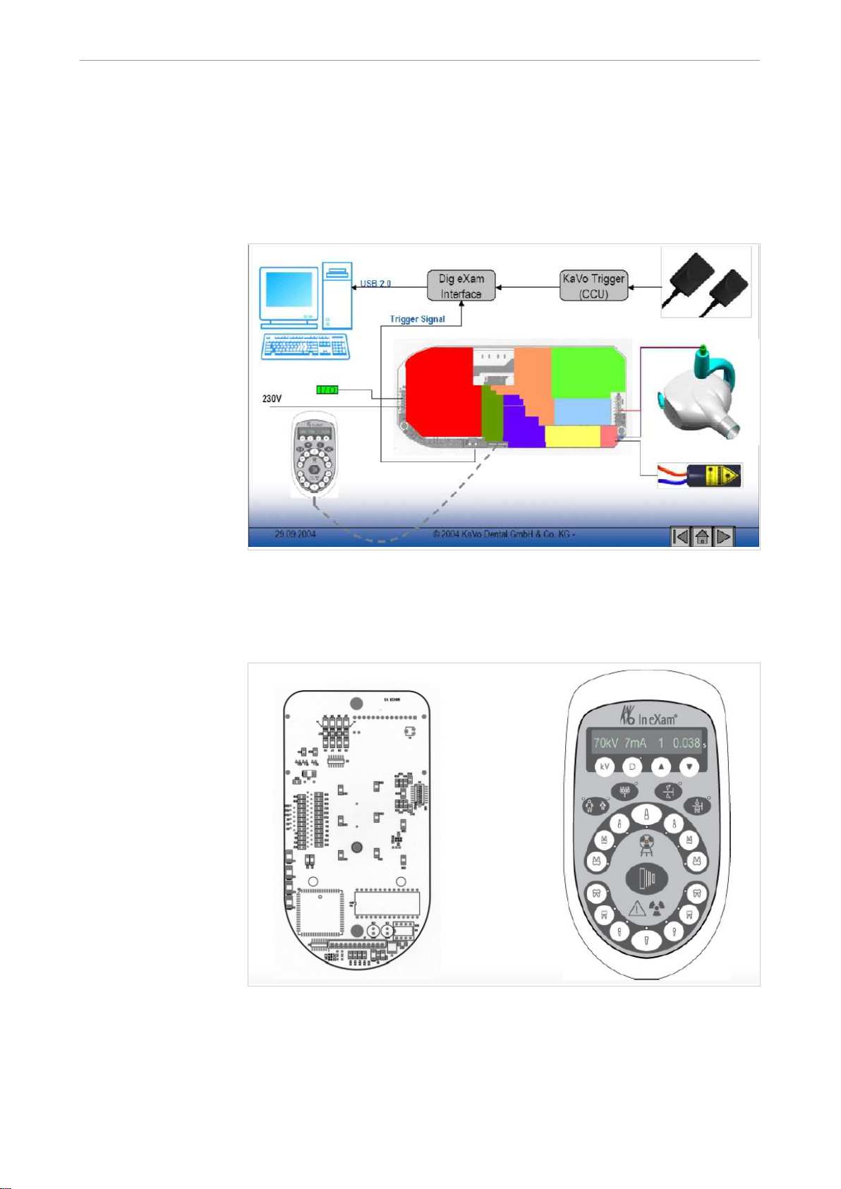
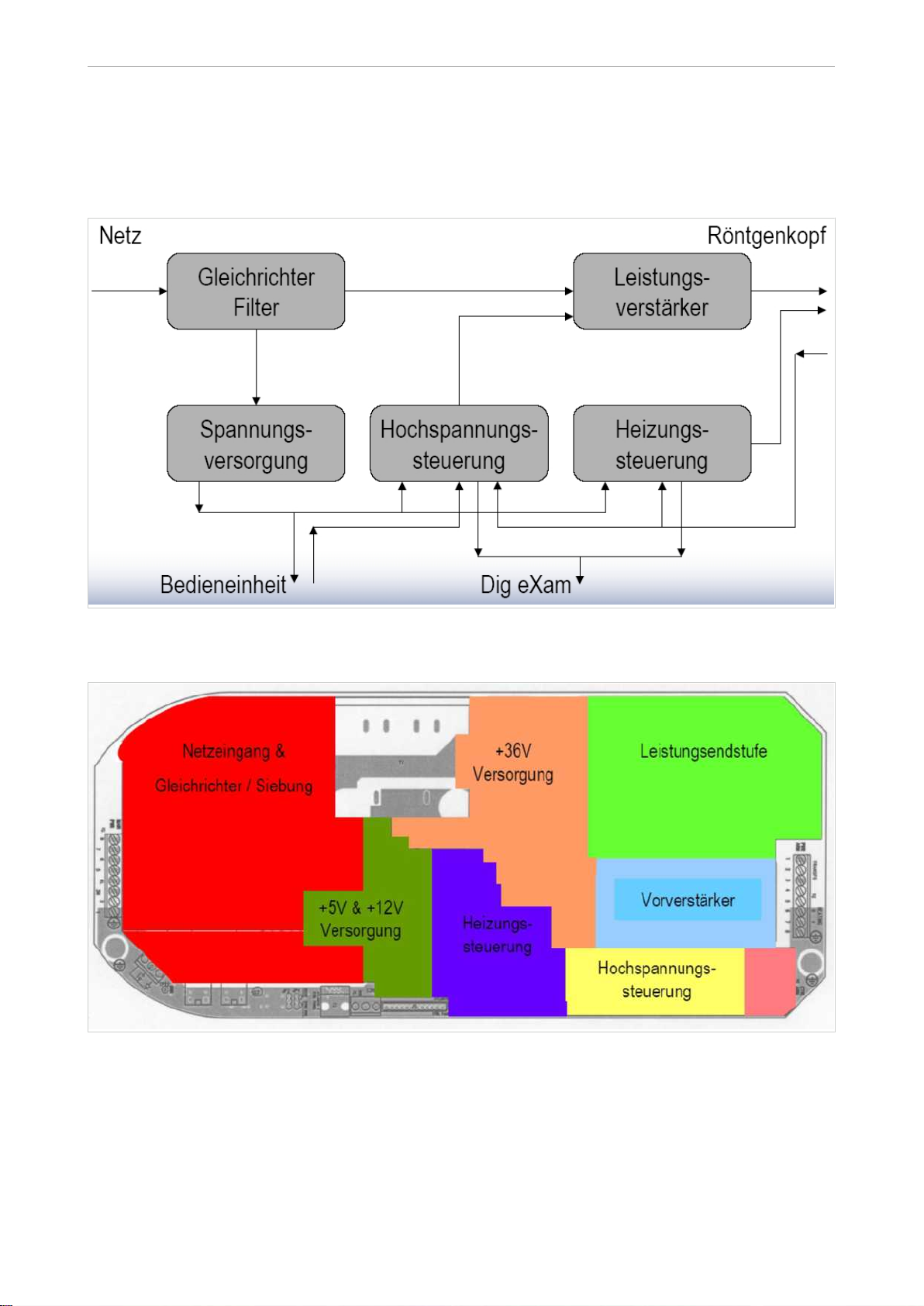
1.1.1 System overview
1.1.2 Control unit
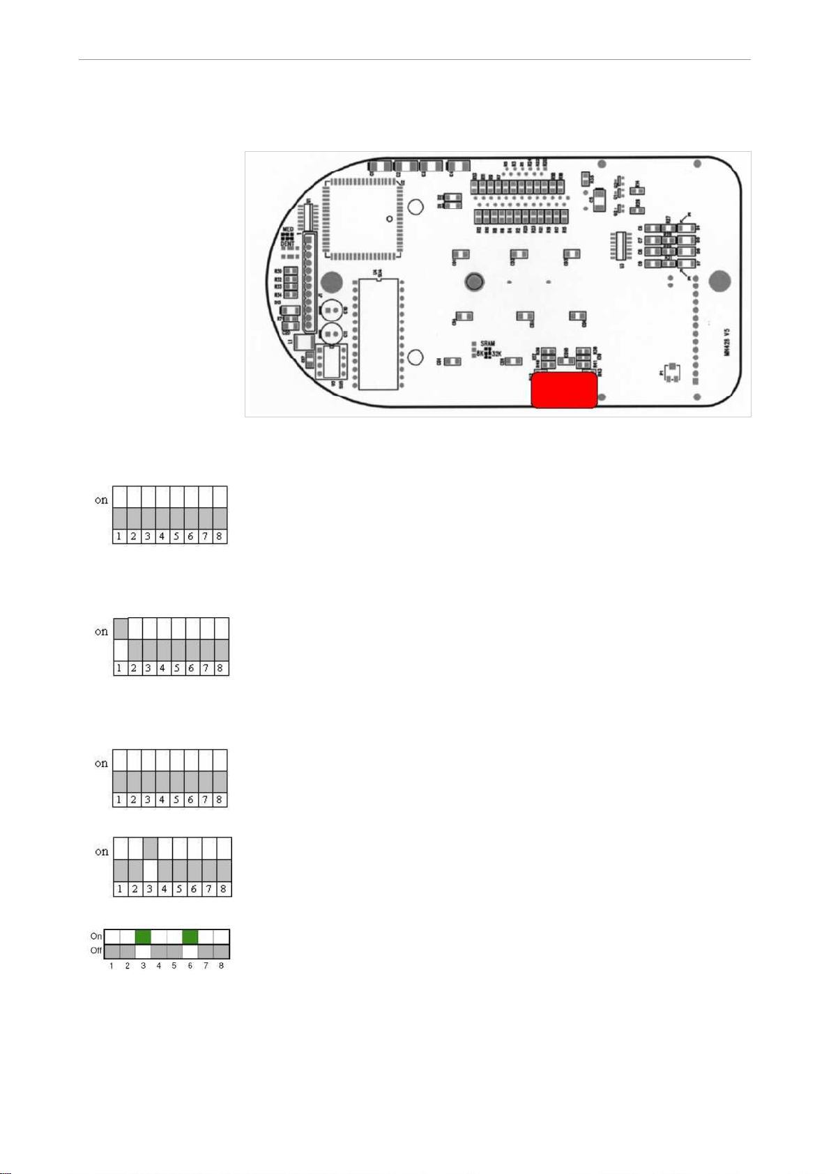
Layout
2/32
Page 5
Technician's instructions KaVo In eXam 3510
1 Product description | 1.1 Description of electronics
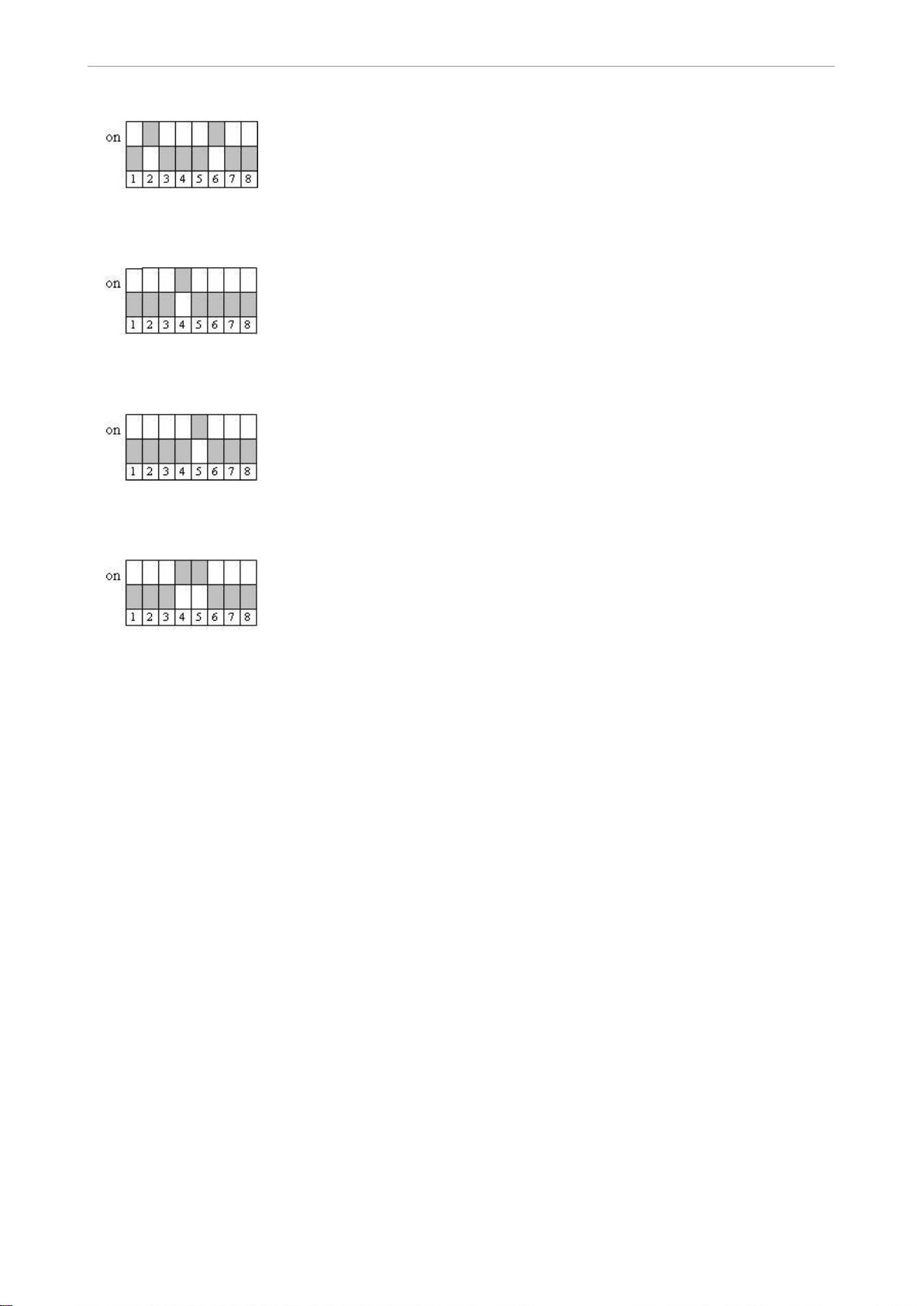
DIP switch
Default
Only the In eXam control unit is connected and active.
Dig eXam-Mode blocked
The tube current cannot be switched to 4 mA.
7 mA is permanently selected.
Special settings for Australia
In Australia, the setting is specified for film correction during the acceptance test
and cannot be changed by the user.
Only film types 0-5 can be selected when the required combination of keys is pres‐
sed.
Only film types 0-7 can be selected when the required combination of keys is pres‐
sed.
3/32
Page 6
Technician's instructions KaVo In eXam 3510
1 Product description | 1.1 Description of electronics
Only film types 0-8 can be selected when the required combination of keys is pres‐
sed.
External exposure switch or control unit
When there is an external exposure switch, the exposure can be independently
triggered by the In eXam control unit or the external switch.
External exposure switch and control unit
Exposure is only triggered when the external exposure switch and the control unit's
exposure switch are simultaneously activated (such as the door safety switch).
External exposure switch
The exposure can only be triggered with the external exposure switch; the control
unit is only used to select the exposure data.
Self test
▶ Turn off the In eXam.
▶ Hold down the D(igital) key, and turn on the In eXam.
▶ Release the D(igital) key when there is nothing on the display.
The following tests are independently run by the system:
▪ The firmware version is displayed
▪ LED Test
▪ Acoustic alarm; four different beeps
▪ Keyboard test
▪ The setting of the DIP switches (SW 1...8) is displayed
▪ The exposure counter is displayed
▪ The exposure counter total is displayed
After a test is successful, the unit switches to user mode.
All LEDs are on, a beep sounds.
The EEPROM has a bad contact in the socket.
Open the control unit, and check the EEPROM for a proper seat.
EEPROM test
▶ Turn off the In eXam
▶ Hold down the film type selection key ▼, and turn on the In eXam
4/32
Page 7
Technician's instructions KaVo In eXam 3510
1 Product description | 1.1 Description of electronics
▶ Once the display no longer shows anything, release the key.
▶ «EEPROM test» appears on the display.
▶ After the test is successful, «EEPROM passed» appears.
▶ The exposure counter is reset
Initialisation
▶ Turn off the In eXam.
▶ Hold down the kV key and D(igital) key, and turn on the In eXam.
▶ Release the key when there is nothing on the display.
▶ The message «Init:Context» appears on the display.
▶ The exposure counter is reset.
Adjust the display brightness
When all functions are okay and there is nothing on the display or the display is dim:
Adjust the display brightness.
▶ Open the In eXam control unit, and adjust with potentiometer P1.
5/32
Page 8
Technician's instructions KaVo In eXam 3510
1 Product description | 1.1 Description of electronics
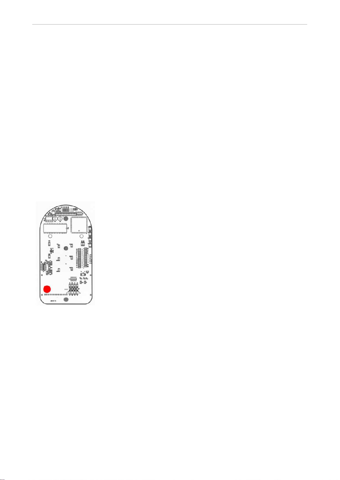
1.1.3 HF Mainboard
Block diagram of mainboard
In eXam HF mainboard
Measure mains voltage
▶ Set the voltmeter to the 300VAC measuring range
▶ Set the voltmeter to the 300VAC measuring range
▶ Connect the measuring tips to L +N
▶ Connect the measuring tips to L +N
6/32
Page 9
Technician's instructions KaVo In eXam 3510
1 Product description | 1.1 Description of electronics
▶ Turn on the In eXam
▶ Turn on the In eXam
▶ Note the no-load voltage: Uo = 230 V (+6%/-10%)
▶ Note the no-load voltage: Uo = 230 V (+6%/-10%)
▶ Set parameters: Film type 9, 60kV, 7mA, occlusal mode
▶ Observe radiation protection measures
▶ Trigger the exposure
▶ Note the load voltage (U
▶ Calculate the voltage fluctuation (Uo – U
▶ When the voltage fluctuation > 9V: Check the power cable
+ 36 V
) during exposure
load
< 9V [~4%])
load
7/32
Page 10
Technician's instructions KaVo In eXam 3510
1 Product description | 1.1 Description of electronics
+ 12 V, isolated
8/32
Page 11

Technician's instructions KaVo In eXam 3510
1 Product description | 1.1 Description of electronics
+ 5 V, isolated
9/32
Page 12

Technician's instructions KaVo In eXam 3510
1 Product description | 1.1 Description of electronics
+ 15 V
10/32
Page 13

Technician's instructions KaVo In eXam 3510
1 Product description | 1.1 Description of electronics
+ 5 V
11/32
Page 14

Technician's instructions KaVo In eXam 3510
1 Product description | 1.1 Description of electronics
Heating voltage
12/32
Page 15

Technician's instructions KaVo In eXam 3510
1 Product description | 1.1 Description of electronics
Anode current
13/32
Page 16

Technician's instructions KaVo In eXam 3510
1 Product description | 1.1 Description of electronics
14/32
Page 17

Technician's instructions KaVo In eXam 3510
1 Product description | 1.2 Functioning of In eXam electronics
1.2 Functioning of In eXam electronics
1.2.1 Basic mode (idling)
▪ Turn on the mains voltage
▪ The mains voltage is applied via F2 (main fuse) and F4 (control circuit fuse) to
the transformer T1, is transformed to 36 VDC, rectified and filtered.
▪ From the 36 VDC, +12 VDC and +5 VDC voltage are generated that are isolated
from the high voltage side. LD 2 and LD 3 shine for the control.
▪ The control unit is supplied with voltage
▪ The control unit runs a self test (buzzer, LEDs and LCD display)
▪ Depending on the setting of the control unit, the HF main board shows the fol‐
lowing:
– at 7mA default > LD 5 shines
– at 70kV default > LD 7 shines
1.2.2 Switch between 4/7mA
▪ Select via the control unit, e.g. 7mA
▪ The relay in the x-ray head is de-energised and thereby bridges one of the re‐
sistors that are series-connected to the cathode >> R > I .
15/32
Page 18

Technician's instructions KaVo In eXam 3510
1 Product description | 1.2 Functioning of In eXam electronics
▪ Switching to 4 mA causes the relay to be energised, and the resistor is again
series-connected >> R > I . LD 5 shines.
1.2.3 Exposure
▪ The trigger in the control unit is activated
▪ In the 1st stage,
– The "Heating Control" signal is emitted by the control unit, and the corre‐
sponding relay is energised. Subsequently, the charging capacitors for cur‐
rent limiter are connected to the mains voltage via a series resistor and the
rectifier, and charged. The voltage supply is therefore available for the power
output stage.
– At the same time, the unisolated voltages +5VDC and +15VDC are applied
at the preamplifier, and LD 1 shines.
– Cathode heating is activated, LD 4 (Vheat) and LD 6 (Fil heat) shine
▪ In the delayed second stage,
– the signal "X ray control" is output by the control unit. Subsequently, the
corresponding relay is operated, whereby the charging resister of the capa‐
citor bank is bridged, and the capacitors are directly supplied from the mains.
– The kV control (described below) is activated, and high voltage is subse‐
quently applied to the tube.
– LD 8 "Cmd KV" shines during the display
1.2.4 Vheat control
The tube current is indirectly regulated by means of the heat voltage.
▪ The reference voltage V
is applied to the comparator. This depends on the
heatref
different components such as tube voltage (60/70 kV) and tube current (4/7 mA).
▪ Depending on this reference voltage, the heating voltage V
is applied to the
heat
filament of the tube.
▪ The heating voltage is simultaneously applied as a feedback signal to the com‐
parator, and compared to the reference voltage V
heatref
. If V
deviates, the
heat
voltage is adjusted and thereby kept constant.
▪ If the heating voltage cannot be adjusted corresponding to the instructions, ex‐
posure is terminated, and in the error message "power error" is output by the
control unit.
1.2.5 kV selection and kV control
▪ The kV is selected with the control unit. By means of the signal CMD kV, a re‐
ference voltage at the comparator is applied to this setting.
▪ The kV controller generates a square wave signal with an f0 that depends on
the preselected kV.
▪ The square wave signal is amplified by the preamplifier and power output stage.
▪ By means of the arm cable, this voltage is transferred to the transformer in the
x-ray head and transformed upward. The higher or lower f0 that is output cor‐
responding to the preselected kV has an effect here. The higher the frequency
of the voltage at the primary winding, the lower the induced voltage at the se‐
condary winding, i.e., the frequency f0 has higher with the selected 60kV than
with the preselected 70kV.
▪ Subsequently, this voltage is quadrupled via an 8-level cascade, and then it is
applied to the anode. Given the relatively higher frequency (~ 300kHz), the low
capacitance of the high-voltage cascade is sufficient to smooth the alternating
16/32
Page 19

Technician's instructions KaVo In eXam 3510
1 Product description | 1.2 Functioning of In eXam electronics
voltage so that a high voltage is applied to the anode of the x-ray that has almost
no residual ripple (DC).
▪ Parallel to the tube is voltage divider by means of which the anode voltage is
returned directly as a feedback signal to the comparator. The reference signal
"CMD kV" and the feedback signal "feedback kV" are compared with each other,
and the frequency f0 is adjusted if there is a difference. This ensures constant
voltage during the entire exposure.
▪ If the anode voltage cannot be controlled within a specific tolerance range, the
high-voltage is interrupted, and the message "kV Error" is output on the control
unit.
17/32
Page 20

Technician's instructions KaVo In eXam 3510
1
2
2 Complete exchange of the x-ray head | 2.1 Remove the x-ray head
2 Complete exchange of the x-ray head
2.1 Remove the x-ray head
Note
Disconnect the In eXam from the mains, and make sure that it cannot be turned
on.
▶ Remove the tube ①.
▶ Remove the lock screws in the x-ray head cover, and remove the cover ②
▶ Unplug the laser diode ③
▶ Unplug the x-ray head from the arm cable ④
▶ Place the scissor arm in a vertical position, and secure it with belts.
Injury from unsecured scissor arm.
18/32
Page 21

Technician's instructions KaVo In eXam 3510
2 Complete exchange of the x-ray head | 2.1 Remove the x-ray head
CAUTION
If the scissor arm is not secured, the arm may shoot up once the x-ray head is
removed. Risk of injury
▶ Before disassembly, attach the safety strap or an equivalent type of retention
before the arm system is lifted out of the bearing.
▶ Loosen the four hexagon socket screws ⑤ at the fastening points
Note
Unscrew the ball-head bolts that prevent disassembly
▶ Hold the x-ray head and remove the loosened hex socket screws.
▶ Remove the x-ray head.
19/32
Page 22

Technician's instructions KaVo In eXam 3510
2 Complete exchange of the x-ray head | 2.2 Install the x-ray head
2.2 Install the x-ray head
▶ Position the x-ray head on the mounting points
▶ Screw back in the 4 hex socket screws ⑤
▶ Connect the x-ray head to the arm cable ④
▶ Plug in the laser diode ③
▶ Screw in the ball-head bolts if applicable
▶ Lock the x-ray head covers in place, and screw them together ②
▶ Remount the tube ①
20/32
Page 23

Technician's instructions KaVo In eXam 3510
2 Complete exchange of the x-ray head | 2.3 Final tasks
2.3 Final tasks
▶ Cut the provided rating plate to size, and affix it on the original rating plate on
the x-ray head.
▶ Check the voltages and functions as described in the section 9 of the installation
instructions, starting the In eXam
▶ Depending on national regulations, run a safety check according to VDE 0751-1
(Installation Instructions, section 10.4)
▶ Depending on national regulations, perform a part acceptance test
▶ Update the x-ray system log
21/32
Page 24

Technician's instructions KaVo In eXam 3510
1
2
3 Exchanging the scissor arm | 3.1 Remove the x-ray head
3 Exchanging the scissor arm
3.1 Remove the x-ray head
Note
Disconnect the In eXam from the mains, and make sure that it cannot be turned
on.
▶ Remove the tube ①.
▶ Remove the lock screws in the x-ray head cover, and remove the cover ②
▶ Unplug the laser diode ③
▶ Unplug the x-ray head from the arm cable ④
▶ Place the scissor arm in a vertical position, and secure it with belts.
Injury from unsecured scissor arm.
22/32
Page 25

Technician's instructions KaVo In eXam 3510
3 Exchanging the scissor arm | 3.1 Remove the x-ray head
CAUTION
If the scissor arm is not secured, the arm may shoot up once the x-ray head is
removed. Risk of injury
▶ Before disassembly, attach the safety strap or an equivalent type of retention
before the arm system is lifted out of the bearing.
▶ Loosen the four hexagon socket screws ⑤ at the fastening points
Note
Unscrew the ball-head bolts that prevent disassembly
▶ Hold the x-ray head and remove the loosened hex socket screws.
▶ Remove the x-ray head.
23/32
Page 26

Technician's instructions KaVo In eXam 3510
3 Exchanging the scissor arm | 3.2 Disassembling the scissor arm
3.2 Disassembling the scissor arm
Note
The puller will help later to pull the new arm line into the support arm. When the old
arm line is pulled out, the puller is pulled into the support arm and left there. Make
sure that there is enough length to stick out at both sides so that the arm line can
be pulled in.
▶ Open the wall box cover.
▶ Disconnect the arm line (terminal block J2, 4-pin plug J6, 2-pin plug or USB plug).
▶ Remove the brake from the bearing block.
▶ The safety strip (or any other fastener) affixed at the bearing block while as‐
sembling the device must be fastened to the arm system.
24/32
Page 27

Technician's instructions KaVo In eXam 3510
3 Exchanging the scissor arm | 3.3 Assembling the scissor arm
3.3 Assembling the scissor arm
▪ Disassemble it as described in Installation Instructions, sections 6.4 & 6.5.
▪ Connect the arm cable as described in Installation Instructions, section 7.1.2
3.3.1 Prepare the arm system
▶ Place the nylon ring on the arm line and then connect the arm line to the line
puller.
▶ Pull mains tubing of the arm line over the exposed cable ends.
CAUTION
▶ Fit approximately 10 cm of the mains cable of the support arm (pull-in aid) and
the mains cable of the arm line together and fix with insulating tape to ensure
they do not separate.
Note
Make sure that all litz wires and plugs are properly insulated since projecting litz
wires can become damage when they are pulled through the support arm, or pro‐
jecting plugs can be torn off.
Undesired unfolding of the scissor arm system during assembly
Injury hazard
Damage to the am system
▶ Before assembly, check if the available distance to the ceiling is sufficient.
▶ Before assembly, check if the safety strap is correctly attached.
▶ Do not remove safety strap while preparing the arm system. Remove the safety
strap during assembly.
25/32
Page 28

Technician's instructions KaVo In eXam 3510
3 Exchanging the scissor arm | 3.3 Assembling the scissor arm
▶ Carefully feed the cable into the extension arm.
▶ Completely attach the extension arm with the bearing bushing onto the scissor
arm pivot pin, making sure that the nylon ring is in the correct position.
Note
Leave the pull-in aid on the arm cable; you will need it later.
26/32
Page 29

Technician's instructions KaVo In eXam 3510
11
12
3 Exchanging the scissor arm | 3.3 Assembling the scissor arm
3.3.2 Mount the arm system
▶ Check that brake ⑪ at the bearing block has been released.
▶ Attach extension arm cover ⑫ of the wall box onto the bearing stud
▶ Position the completely pre-assembled arm system close to the bearing block.
▶ With the aid of the used pull rope pull the arm cable through the bearing block
from the top.
See also:
▶ Use the bearing stud to insert the extension arm into the bearing block from
above. Make sure that the bearing stud is fully held in the bearing bushing. As
it has been designed to be quite a tight fit, you may need to raise the arm system
up slightly to prevent the bearing stud from canting in the bearing bushing.
▶ Remove the pull-in aid and insulating tape from the arm cable
▶ Remove the safety strap from the arm system and fasten it at the bearing block
to the arm line so that it can be reattached if the arm system is disassembled.
3.3.3 Wiring
Note
Run the individual connectors so that they do run over the stop bolt for the cover.
27/32
Page 30

Technician's instructions KaVo In eXam 3510
3 Exchanging the scissor arm | 3.4 Final tasks
3.4 Final tasks
▶ Check the adjustment of the arm system and adjust it if necessary according to
installation instructions
▶ Check the voltages and functions (as described in the section, "Starting the In
eXam" of the installation instructions).
▶ Depending on national regulations, run a safety check according to VDE 0751-1
(Installation Instructions, section 10.4)
▶ Close the wall box cover
▶ Create an exposure for consistency and check it
▶ Fill in the provided rating plate (both values can be taken from the original rating
plate):
Check the voltage version
Enter the serial number of the source head
▶ Update the x-ray system log
28/32
Page 31

Technician's instructions KaVo In eXam 3510
4 Troubleshooting for service | 4.1 Error messages on the display
4 Troubleshooting for service
4.1 Error messages on the display
Error message Reason Display Solution
Error: Cooling The x-ray head is too hot
The message also ap‐
pears when the In eXam
was only turned on for the
exposure. The measure‐
ment is not an actual mea‐
surement but only a calcu‐
lated value.
OP.Error The exposure key was re‐
leased before exposure
was over.
kV Error The maximum voltage in
the tube deviates ≥10 %
from the anticipated value.
Power Error The mains voltage is too
low, or the fluctuations are
too high.
No heating voltage at the
x-ray tube.
The display appears upon
touching the exposure
key.
An error message appears
in the display, and the re‐
maining time is shown.
An acoustic alarm sounds.
The error message is
shown on the display by
pressing the exposure
key.
The error message is
shown on the display by
pressing the exposure
key.
Turn on the In eXam and
leave it connected to the
mains until the message
disappears.
Press any key on the con‐
trol unit.
See the following section
LED V
The voltage between GND
and V
heat
See the following section
must appear.
heat
must be 3-4 VCD
29/32
Page 32

Technician's instructions KaVo In eXam 3510
4 Troubleshooting for service | 4.2 Measurements
4.2 Measurements
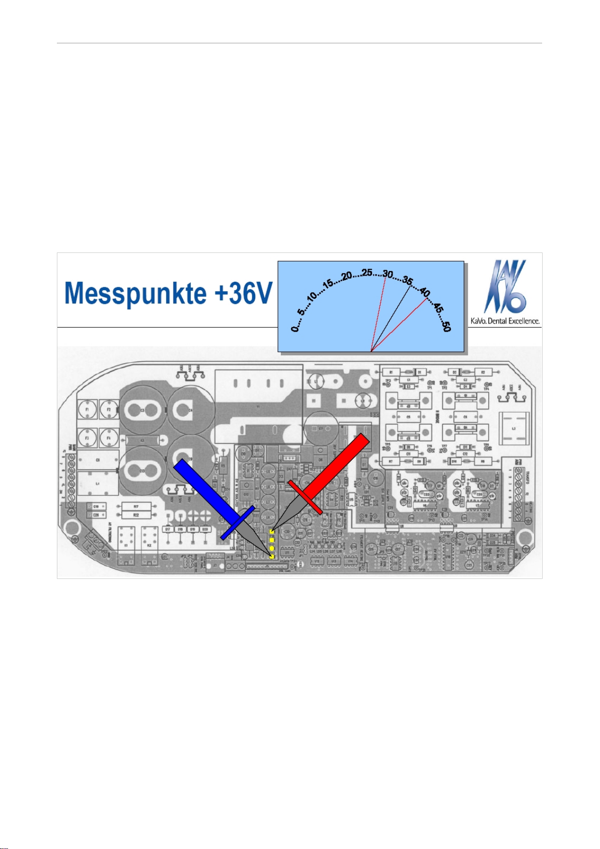
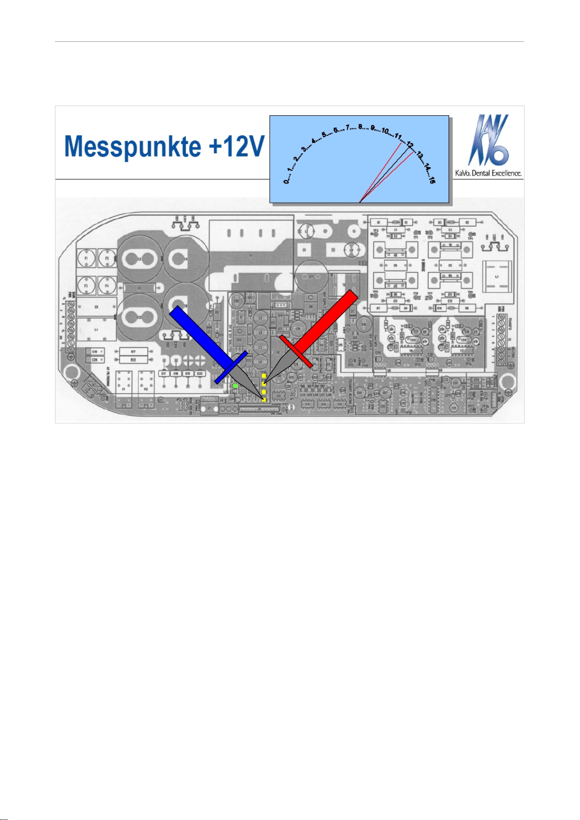
4.2.1 Voltage measurement on the mainboard
Test point
[name]
23 [GND] 15 [+ 36 V] 30 VDC < ...< 41 VDC
23 [GND] 16 [+ 12 V (LD 2)] 11.4 VDC < ...< 12.6 VDC
23 [GND] 17 [+ 5 V (LD 3)] 5.3 VDC < ...< 5.9 VDC
11 [0 V] 9 [+ 15 V (LD 1)] 13.5 VDC < ...< 15 VDC
11 [0 V] 12 [+ 5 VIN] 4.8 VDC < ...< 5.4 VDC
25 [GND] 24 [V
20 [0 mA] 21 [RTN mA] Setting: 4mA 3.4 VDC < ...< 4.6 VDC
20 [0 mA] 21 [RTN mA] Setting: 7mA 6 VDC < ...< 8 VDC
Test point [name] Range
(only measurable during the exposure)
(only measurable during the exposure)
] 3 VDC < ...< 4 VDC
heat
(only measurable during the exposure)
(only measurable during the exposure)
(only measurable during the exposure)
Note
If at least one value lies outside of the tolerance range, the supply electronics must
be exchanged.
30/32
Page 33

Technician's instructions KaVo In eXam 3510
4 Troubleshooting for service | 4.2 Measurements
4.2.2 Measure resistance on the main board
Test point [name] Test point [name] Range
27 [0 kV] 28 [+ kV] 10.6 < ...< 12.6 Ω
20 [0 mA] 21 [RTN mA] 1 kΩ
20 [0 mA] J2 - 8 [PWR ARM] ~ 0 Ω
20 [0 mA] J2 - 7 [PWR ARM] ~ 0 Ω
20 [0 mA] J2 - 6 [PWR ARM] ~ 0 Ω
20 [0 mA] J2 - 3 [PWR ARM] ∞
20 [0 mA] J6 - 1 [CTRL ARM] ~ 3 kΩ
J2 - 1 [PWR ARM] J2 - 3 [PWR ARM] ~ 0 Ω
Note
If at least one value is incorrect, the supply electronics or the arm cable can be
detected.
Disconnect the arm cable
Test point [name] Test point [name] Range
27 [0 kV] 28 [+ kV] 86.5 < ...< 95.5 Ω
20 [0 mA] 21 [RTN mA] 1 kΩ
20 [0 mA] J2 - 8 [PWR ARM] ~ 0 Ω
20 [0 mA] J2 - 6 [PWR ARM] ~ 0 Ω
20 [0 mA] J2 - 3 [PWR ARM] ∞
20 [0 mA] J6 - 1 [PWR ARM] ∞
1 [0 V] 3 [G 1] 10 kΩ
2 [0 V] 4 [G 2] 10 kΩ
6 [Tr 1] 5 [G 4] 10 kΩ
7 [Tr 2] 8 [G 5] 10 kΩ
Note
If at least one value lies outside of the tolerance range, the supply electronics must
be exchanged.
Cable disconnected
Colour / Test Point Colour / Test Point Value Tolerance
blue / J2-6 red / J6-2 ∞
blue / J2-6 yellow / J6-4 12 < …< 14.6 kΩ
blue / J2-6 green / J6-1 3 kΩ
blue / J2-6 purple / J2-7 ~ 0 Ω
blue / J2-6 brown / J2-1 ∞
blue / J2-6 gn/yl/ / J2-8 ~ 0 Ω
gn/yl/ J2-8 brown / J2-1 ∞
gn/yl/ J2-8 shielding / J6-3 ~ 0 Ω
brown / J2-3 orange / J2-3 ~ 0 Ω
Note
If at least one value lies outside of the tolerance range, exchange the arm cable or
x-ray head.
31/32
Page 34

Technician's instructions KaVo In eXam 3510
4 Troubleshooting for service | 4.3 Identifying errors
4.3 Identifying errors
Malfunction Cause Remedy
Nothing works. The device is not directly connec‐
ted.
The fuse on the main board is de‐
fective.
The building fuse has tripped. ▶ Turn on the fuse.
No display on the control unit. The In eXam control unit is not
connected.
The control unit line is defective. ▶ Replace the cable.
The fuse is defective. ▶ Exchange the fuse.
In eXam control unit defective ▶ Exchange the In eXam timer.
No x-rays. The x-ray tube is too hot. ▶ Wait until the "COOLING" mes‐
The release switch is defective. ▶ Run a self test of the In eXam
The dip switch is not adjusted cor‐
responding to the installation.
Image too bright or dark Wrong type of film selected. ▶ Use correct setting.
Tube is in the wrong position. ▶ Correct the position.
Exposure time is too long/short. ▶ Correct the exposure time.
X-rays are okay, but picture is too
bright/dark.
Film development
X-rays are okay, but picture is too
bright/dark.
Other reasons.
Developing time to short/long. ▶ Note the description of the de‐
The developer is too cold/warm. ▶ Check and adjust the tempera‐
The chemicals are too old. ▶ Replace the chemicals.
mA setting is wrong. ▶ Film setting: Select 7 mA.
The film was inserted backwards. ▶ When inserting, note the mar‐
The In eXam was not properly in‐
stalled.
▶ Check the connections.
▶ Exchange the fuse.
▶ Correctly connect the In eXam
timer.
sage disappears.
control unit and exchange it if
necessary.
▶ Check the settings of the dip
switches and external safety
switch.
veloping machine.
ture.
Sensor setting: Select 4mA.
king on the film.
▶ Inform a qualified technician.
32/32
Page 35

Page 36

1.003.5058 · KF · 20080508 - 01 · en
 Loading...