

KaVo ELECTROmatic M, ELECTROmatic C, ELECTROmatic PC, ELECTROmatic PM, ELECTROmatic TM Instructions For Use Manual
...Page 1

Instructions for use
ELECTROmatic M/C and PM/PC
Page 2

Distributed by:
KaVo Dental Technologies, LLC
11727 Fruehauf Drive
Charlotte, NC 28273 USA
Phone: 847 550 6800
Fax: 847 550 6825
Manufacturer:
Kaltenbach & Voigt GmbH
Bismarckring 39
88400 Biberach
Germany
www.kavo.com
Page 3

Instructions for use ELECTROmatic M/C and PM/PC
Table of contents
Table of contents
1 User notes........................................................................................................................... 6
1.1 User guidelines.............................................................................................................. 6
1.1.1 Abbreviations ..................................................................................................... 6
1.1.2 General marks and symbols................................................................................. 6
1.2 Target group................................................................................................................. 7
1.3 Service ......................................................................................................................... 7
1.3.1 Repair Service.................................................................................................... 7
1.4 Warranty terms and conditions........................................................................................ 8
1.5 Transportation and storage............................................................................................. 8
1.5.1 Damage in transit............................................................................................... 8
1.5.2 Information on the packaging: Storage and transport............................................. 9
1.6 Disposal........................................................................................................................ 10
1.7 Disposal of electronic and electrical devices ...................................................................... 11
2 Safety.................................................................................................................................. 12
2.1 Infection hazard ........................................................................................................... 12
2.2 Explosion hazard area.................................................................................................... 12
2.3 Technical condition......................................................................................................... 12
2.4 Ingress of liquids ........................................................................................................... 13
2.5 Accessories and combination with other equipment........................................................... 13
2.6 Qualification of personnel................................................................................................ 14
2.7 Service and repair.......................................................................................................... 14
2.8 Electromagnetic fields .................................................................................................... 14
3 Product description ............................................................................................................16
3.1 Purpose - proper use...................................................................................................... 16
3.2 Scope of delivery........................................................................................................... 18
3.3 ELECTROmatic – Versions............................................................................................... 22
3.4 Motor hose.................................................................................................................... 22
3.5 Control panel (PM/PC only)............................................................................................. 23
3.6 Technical specifications of the ELECTROmatic ................................................................... 25
3.7 Symbols on product and rating plate................................................................................ 28
3.8 Power supply type 4882 ................................................................................................. 29
3.9 Technical data for the power supply type 4882 ................................................................. 29
3.10Symbols on the nameplate of the type 4882 power supply................................................. 30
4 Installation .........................................................................................................................32
4.1 Location........................................................................................................................ 32
4.2 Installation positions ...................................................................................................... 32
4.3 Preparing the installation................................................................................................ 34
4.4 Installation position 1: Mount below a holder.................................................................... 34
4.5 Installation position 2: Mount on the side of a holder......................................................... 36
4.6 Installation position 3: Mount on a holder or on the backside of a holder ............................. 38
4.7 Installation position 4: Mount control panel as remote control (PM/PC only)......................... 40
4.7.1 Disconnect the control panel from the control unit and install it on the mounting
bracket.............................................................................................................. 40
4.7.2 Mount control panel on a holder / on the backside of a holder ................................. 42
3 / 80
Page 4

Instructions for use ELECTROmatic M/C and PM/PC
Table of contents
4.7.3 Mount control panel on the side of a holder ........................................................... 43
4.7.4 Mount control panel to cabinet/wall ...................................................................... 46
4.8 Connect the ELECTROmatic ............................................................................................ 47
4.9 Check the installation ..................................................................................................... 47
5 Commissioning ................................................................................................................... 48
5.1 Connection.................................................................................................................... 48
5.1.1 Electrical operating conditions .............................................................................. 48
5.1.2 Connecting the ELECTROmatic............................................................................. 48
5.1.3 Connecting the motor.......................................................................................... 49
5.1.4 Connect the motor cord....................................................................................... 50
5.1.5 Connect the power supply .................................................................................. 50
5.2 Calibrating the foot control.............................................................................................. 51
5.3 Measure cooling air quantity at motor coupling ................................................................. 52
5.4 Making the device settings.............................................................................................. 52
6 Operation............................................................................................................................ 56
6.1 Switching the ELECTROmatic on/off................................................................................. 56
6.2 Start the motor ............................................................................................................. 57
6.3 Regulating the spray water............................................................................................. 57
6.4 Changing the speed setting............................................................................................. 58
6.5 Changing the direction of rotation.................................................................................... 58
6.6 Protection function SAFEdrive (PM/PC only)...................................................................... 58
6.6.1 Turning SAFEdrive on / off................................................................................... 59
6.6.2 Use with the SAFEdrive function........................................................................... 60
7 Decommissioning ............................................................................................................... 62
7.1 Disconnecting the electrical connection ............................................................................ 62
7.2 Disconnecting the ELECTROmatic from the treatment unit ................................................. 62
7.3 Unplugging the motor/COMFORTdrive.............................................................................. 62
8 Processing steps in accordance with DIN EN ISO 17664...................................................63
8.1 Cleaning ....................................................................................................................... 63
8.1.1 Preparation at the site of use ............................................................................... 63
8.1.2 Manual external cleaning..................................................................................... 63
8.1.3 Manual cleaning of the inside ............................................................................... 63
8.1.4 Mechanical cleaning of the exterior and interior...................................................... 64
8.2 Disinfection................................................................................................................... 64
8.2.1 Manual external disinfection................................................................................. 64
8.2.2 Manual disinfection of the interior......................................................................... 64
8.2.3 Mechanical disinfection of the exterior and interior ................................................. 65
8.3 Packaging..................................................................................................................... 65
8.4 Sterilization................................................................................................................... 65
8.5 Storage ........................................................................................................................ 65
8.6 Service, inspection and testing after processing ................................................................ 65
9 Maintenance .......................................................................................................................66
9.1 Changing the filter - water inlet....................................................................................... 66
9.2 Replacing the LED lamp of the KL 703 motor.................................................................... 67
9.3 Replacing the LED lamp of the COMFORTbase................................................................... 68
9.4 Replacing the motor hose............................................................................................... 68
4 / 80
Page 5

Instructions for use ELECTROmatic M/C and PM/PC
Table of contents
10Troubleshooting .................................................................................................................70
11Accessories and consumables............................................................................................73
12Information on electromagnetic compatibility...................................................................74
12.1Guidelines and manufacturer's declaration - electromagnetic emission ................................ 74
12.2Guidelines and manufacturer's statement - Electromagnetic immunity ................................ 74
12.3Guidelines and manufacturer's statement - Electromagnetic immunity ................................ 75
12.4Recommended safe distances between portable and mobile HF telecommunications
equipment and the ELECTROmatic................................................................................... 77
5 / 80
Page 6
Instructions for use ELECTROmatic M/C and PM/PC
1 User notes | 1.1 User guidelines
1 User notes
1.1 User guidelines
Requirement
Read these instructions prior to first startup to avoid misuse and prevent damage.
Requirement
If other languages are required, they can be requested from the responsible
KaVo branch. Prior approval from KaVo must be obtained before copying and
passing on the instructions for use.
1.1.1 Abbreviations
Abbreviation
IFU Instructions for use
CI Care instructions
Short
IfU
AI Assembly instructions
TI Technician's instructions
IEC International Electrotechnical Commission
RI Repair instructions
RK Retrofitting kit
AS Assembly set
CK Conversion kit
EP Enclosed parts
EMC Electromagnetic compatibility
PI Processing instructions
Explanation
Short instructions for use
1.1.2 General marks and symbols
See section on Hazard levels
Important information for users and technicians
CE mark (European Community). A product bearing this mark meets
the requirements of the applicable EU directive.
Action required
Hazard levels
The warning and safety notes in this document must be observed to prevent
personal injury and property damage. The warning notes are designated as
shown below:
6 / 80
Page 7
Instructions for use ELECTROmatic M/C and PM/PC
1 User notes | 1.2 Target group
DANGER
In cases which – if not prevented – directly lead to death or severe injury.
WARNING
In cases which – if not prevented – can lead to death or severe injury.
CAUTION
In cases which – if not prevented – can lead to minor or moderate injury.
NOTICE
In cases which – if not prevented – can lead to property damage.
1.2 Target group
This document is for dentists, dental practice staff and service staff.
1.3 Service
Note
Send the product in for a service check every two years.
In this service check, the safety checks are performed according to IEC 62353 VDE 0751-1.
Please direct all questions regarding the product, service and maintenance to
the
KaVo Technical Service:
Toll-free: 1-888-ASK-KAVO (888-275-5286)
Email: techservice@kavokerr.com
Please refer to the serial number of the product in all inquiries!
1.3.1 Repair Service
For repairs, please contact KaVo Repair Service.
For scheduling or if you have any questions, please contact:
KaVo Repair Service
KaVo Dental Technologies, LLC
11727 Fruehauf Drive
Charlotte, NC 28273 USA
Toll-free Direct Customer Service: 1-888-ASK-KAVO (888-275-5286)
Email: techservice@kavokerr.com
www.kavo.com
7 / 80
Page 8

Instructions for use ELECTROmatic M/C and PM/PC
1 User notes | 1.4 Warranty terms and conditions
1.4 Warranty terms and conditions
Within the scope of the applicable KaVo delivery and payment conditions, KaVo
guarantees proper function, absence of defects in material and workmanship
for a period of 36 months from the date of purchase as confirmed by the salesperson.
In case of justified complaints, KaVo will honor its warranty with a free replacement or repair.
The warranty does not cover defects and their consequences that arose or may
have arisen due to natural wear, improper handling, cleaning or servicing, noncompliance with operating, maintenance or connection instructions, corrosion,
contaminated media supply or chemical or electrical influences deemed abnormal or impermissible in accordance with factory specifications.
The warranty does not usually cover lamps, light conductors made of glass and
glass fibers, glassware, rubber parts and the colorfastness of plastic parts.
The warranty shall be void if defects or their consequences may be related to
modifications of or changes to the product. Warranty claims can only be asserted when they are immediately reported to KaVo in writing.
This notification must be accompanied by a copy of the invoice or delivery note
on which the manufacturing number is clearly visible. In addition to the warranty, the statutory warranty claims of the purchaser also apply with a warranty period of 12 months.
Defects and the consequences of defects, in particular because of insufficient
servicing of the water filter, are not covered by the warranty.
1.5 Transportation and storage
1.5.1 Damage in transit
In Germany
If the packaging is visibly damaged on delivery, please proceed as follows:
1. The recipient of the package must record the loss or damage on the delivery
receipt. The recipient and the representative of the shipping company must
sign this delivery receipt.
2. Leave the product and packaging in the condition in which you received it.
3. Do not use the product.
4. Report the damage to the shipping company.
5. Report the damage to KaVo.
6. Consult with KaVo first, before returning a damaged product.
7. Send the signed delivery receipt to KaVo.
If the product is damaged but there was no discernable damage to the packaging on delivery, proceed as follows:
1. Report the damage to the shipping company immediately and no later than
7 days after delivery.
2. Report the damage to KaVo.
3. Leave the product and packaging in the condition in which you received it.
4. Do not use a damaged product.
8 / 80
Page 9
Instructions for use ELECTROmatic M/C and PM/PC
1 User notes | 1.5 Transportation and storage
Note
Failure on the part of the recipient to comply with any of the above-mentioned obligations will mean that the damage will be considered to have
arisen only after the time of delivery (in accordance with the General German
Freight Forwarders' Terms and Conditions, Art. 28).
Outside of Germany
Note
KaVo shall not be held liable for damage arising from transportation.
The shipment must be checked on arrival.
If the packaging is visibly damaged on delivery, please proceed as follows:
1. The recipient of the package must record the loss or damage on the delivery
receipt. The recipient and the representative of the shipping company must
sign this delivery receipt.
Without this evidence, the recipient will not be able to assert a claim for
damages against the shipping company.
2. Leave the product and packaging in the condition in which you received it.
3. Do not use the product.
If the product is damaged but there was no discernable damage to the packaging on delivery, proceed as follows:
1. Report any damage to the shipping company immediately and no later than
7 days after delivery.
2. Leave the product and packaging in the condition in which you received it.
3. Do not use a damaged product.
Note
If the recipient fails to comply with any of the above-mentioned obligations,
the damage will be considered to have arisen only after the time of delivery
(in accordance with CMR law, Chapter 5, Art. 30).
1.5.2 Information on the packaging: Storage and
transport
Note
Please keep the packaging in case you need to return the product for servicing or repair.
The symbols printed on the outside are for transportation and storage, and
have the following meaning:
Caution
Follow instructions for use
Please note the electronic instructions for use
HIBC Code
9 / 80
Page 10
Instructions for use ELECTROmatic M/C and PM/PC
1 User notes | 1.6 Disposal
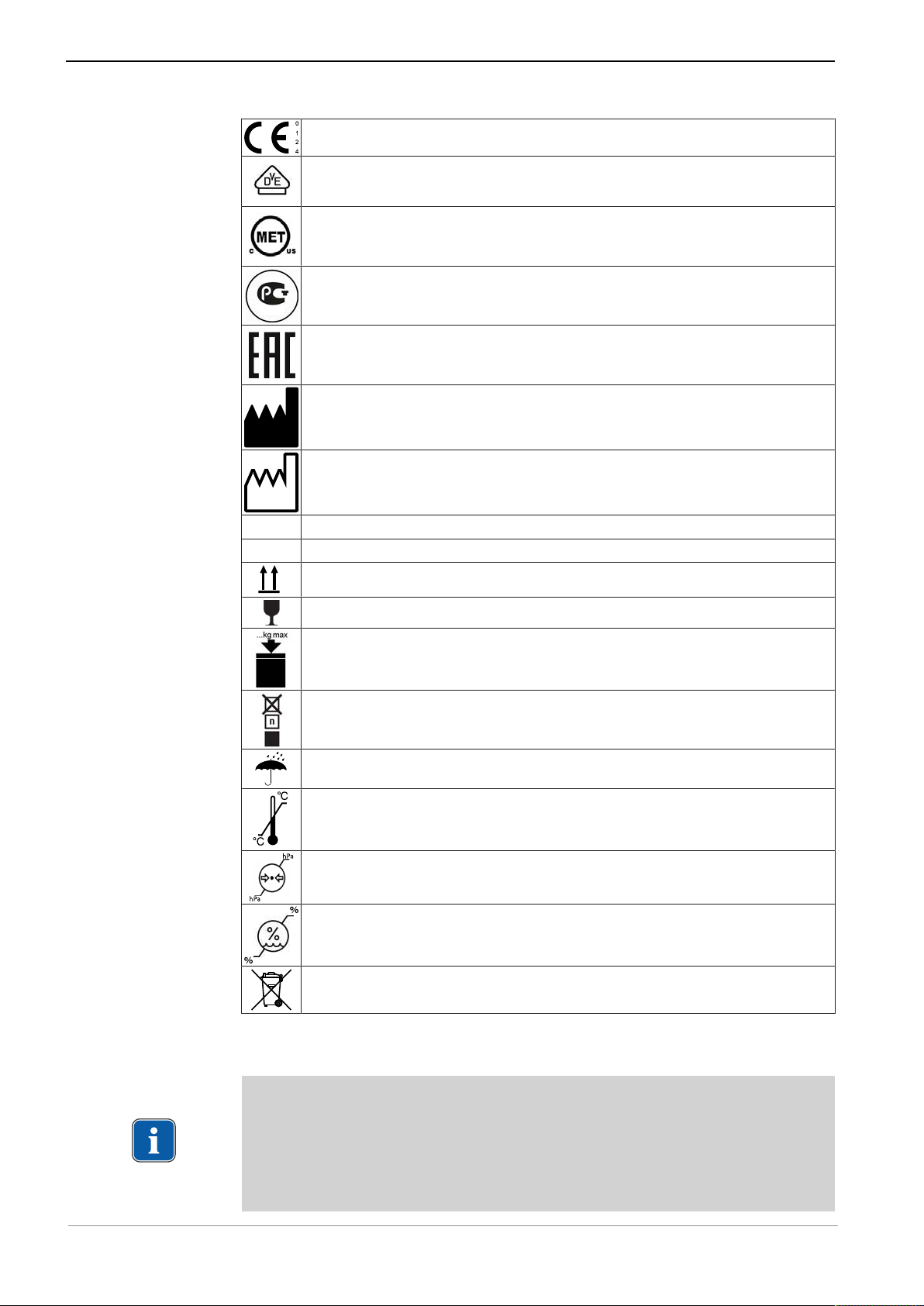
CE mark (European Conformity mark)
VDE mark
MET mark
GOST R certification
EAC conformity mark (Eurasian Conformity = Eurasische Konformität)
Manufacturer
Date of manufacture: Year - Month - Day
SN Serial number
REF Catalog number
Transport upright with the arrows pointing upwards!
Fragile - protect against impact!
Permissible stacking load
Stacking limit by number
Protect from moisture!
Temperature range
Air pressure
Humidity
Do not dispose this product into the ordinary municipal waste or
garbage system
1.6 Disposal
Note
Any waste produced must be recycled or disposed of in strict compliance with
all applicable national regulations in a manner which is safe for both people
and the environment.
If you have any questions regarding proper disposal of the KaVo product,
please contact the KaVo branch.
10 / 80
Page 11

Instructions for use ELECTROmatic M/C and PM/PC
1 User notes | 1.7 Disposal of electronic and electrical devices
1.7 Disposal of electronic and electrical devices
Note
In accordance with EC directive 2012/19 concerning waste electrical and
electronic equipment, this product is subject to the cited directive and must
be disposed of accordingly within Europe.
For more information, please visit www.kavo.com or contact your specialized
dental supplier.
For final disposal:
In Germany
To return an electrical device, you need to proceed as follows:
1. On the homepage www.enretec.de of enretec GmbH, you can download a
form for a disposal order under the menu item, eom. Download the disposal
order or complete it as an online order.
2. Enter the corresponding information to complete the order, and submit it as
an online order or by fax +49 (0)3304 3919 590 to enretec GmbH.
The following contact options are also available for questions and for initiating a disposal order:
Telefon: +49 (0) 3304 3919 500
Email: eom@enretec.de and
Postal address: enretec GmbH, Geschäftsbereich eomRECYCLING®
Kanalstraße 17
D-16727 Velten
3. A unit that is not permanently installed will be picked up at the office.
A permanently installed unit will be picked up at the curb at your address on
the agreed date.
The owner or user of the device will have to bear the cost of disassembly,
transportation and packaging.
International
For country-specific information on disposal, contact your dental supplier.
11 / 80
Page 12

Instructions for use ELECTROmatic M/C and PM/PC
2 Safety | 2.1 Infection hazard
2 Safety
The instructions for use are a component of the product and must be read carefully prior to use and be accessible at all times.
The device may only be used in accordance with the intended use, any other
type of use is not permitted.
2.1 Infection hazard
Patients, users or third parties can be infected by contaminated medical devices.
▶ Take suitable personal protective measures.
▶ Follow the instructions for use of the components.
▶ Before initial startup and after each use, process the product and acces-
sories appropriately.
▶ Carry out the processing as described in the instructions for use. The proce-
dure has been validated by the manufacturer.
▶ If you deviate from this procedure, it is essential to make sure that the pro-
cessing is effective.
▶ Process the product and accessories appropriately before disposal.
2.2 Explosion hazard area
Electrical sparks in the product can lead to explosion or fire.
▶ Do not use product in explosion hazard areas.
▶ Do not operate the product in an oxygen-enriched atmosphere.
▶ Do not use the product in the vicinity of flammable gases.
2.3 Technical condition
A damaged device or components can injure patients, users and third parties. A
damaged power cable or missing protective conductor can lead to electrical
shock.
▶ Use the device and components only if there is no damage on the outside.
▶ Check the power cable before use.
▶ Connect only to sockets with a protective contact that meet the respective
national regulations.
▶ Check the proper working order and proper condition of product and acces-
sories before each use.
▶ Have parts with sites of breakage or surface changes checked by the Ser-
vice.
▶ Safety checks may only be performed by trained service personnel.
▶ Perform a test run with the handpiece before each use.
▶ If any of the following defects on the product or accessories occurs, stop
working and have the service personnel carry out repair work:
▪ Malfunctions
▪ Damage
▪ Irregular running noise
▪ Excessive vibration
12 / 80
Page 13

Instructions for use ELECTROmatic M/C and PM/PC
2 Safety | 2.4 Ingress of liquids
▪ Overheating
▪ Dental bur or diamond is not firmly locked in the handpiece
Careless setup/installation of the product or accessories can cause injury to patients, users and third parties. Power supplies and/or cords/hoses on the floor
can cause slipping or tripping.
▶ Power supply and cord/hoses need to be set-up/routed appropriately such
that they are not on the floor.
Note
The SAFEdrive function is a monitoring function for detection of defective
high-speed handpieces. Defective high-speed handpieces can heat up
strongly during use due to additional friction, especially in the head region,
and possibly cause burn injuries. KaVo recommends to activate the
SAFEdrive function during treatments inside the oral cavity in order to reduce
the risk of burn injuries caused by defective high-speed handpieces.
2.4 Ingress of liquids
Use of the product in moist or electrically conductive environments can lead to
electrical shock and injury to patients, users and third parties.
▶ Use the product in dry environments exclusively.
▶ Use the product only in environments that are not electrically conductive.
▶ Protect openings of the product from any ingress of liquids.
▶ Do not place the product in a trough-like container.
▶ If any liquid is detected on the device, disconnect the power cable from the
supply mains right away and do not touch the product.
▶ Make sure that the surface of the product is absolutely dry before plugging
the power cable back into the socket.
▶ After interventions on and repairs of the device and before re-use, have the
service personnel perform a safety check on the device.
2.5 Accessories and combination with other equipment
Use of un-authorized accessories on the device or un-authorized modifications
to the device can lead to injury.
▶ Only use accessories that have been approved for combination with the
product by the manufacturer.
▶ Only use accessories that are equipped with standardized interfaces.
▶ Do not make any modifications to the device unless these have been ap-
proved by the manufacturer of the product.
Improper use of handpieces can cause injuries.
You need to comply with the following guidelines to ensure the safe use of the
electrically-driven handpieces:
▶ Comply with the instructions for use of the respective handpiece.
▶ Check the speed setting each time you turn on the device.
▶ Comply with the permissible maximum speed and maximum contact pres-
sure of the tools as specified by the tool manufacturer.
▶ Comply with the servicing instructions for handpieces as specified in the re-
spective instructions for use.
13 / 80
Page 14

Instructions for use ELECTROmatic M/C and PM/PC
2 Safety | 2.6 Qualification of personnel
▶ Never press the push-button during operation of the device.
▶ Never use the push-button to lift the cheek or tongue.
Improper use of tools, e.g. wrong drill lengths and files, can cause injuries.
▶ Comply with manufacturer's instructions (mode of operation, speed, torque
levels, torsion resistance, etc.), and use the files according to their intended
use.
2.6 Qualification of personnel
Application of the product by users lacking appropriate medical training can injure the patient, the user or third parties.
▶ Make sure that the user has read and comprehends the instructions for use.
▶ Only employ the device if the user has the appropriate medical training.
▶ Comply with national and regional regulations.
The bluish LED light of the motors can damage the cornea or lens of the eye.
▶ Do not gaze into the lamp when it is in operation.
▶ Use adequate shielding for eye protection.
2.7 Service and repair
Servicing work that is described in the "Servicing" chapter of the present Instructions for Use can be performed by the operator/user.
Repairs and safety checks may only be performed by trained service personnel.
The following persons are authorized to do this:
▪ Service technicians of KaVo branches after the appropriate product training
▪ Service technicians of KaVo authorized dealers after the appropriate product
training
▪ Independent service technicians after the appropriate product training
Comply with the following items during all servicing work:
▶ Have the service and testing tasks carried out in accordance with the autho-
rized personal.
▶ After interventions on and repairs of the device and before re-use, have the
service personnel perform a safety check on the device.
▶ The device should be serviced, cleaned, and stored in a dry location, and
should be disconnected from the power system, according to instructions, if
it is not to be used for extended periods.
Note
KaVo provides wiring diagrams, component lists, descriptions, calibration instructions or other information on request to support the service personnel
during repair work.
2.8 Electromagnetic fields
Electromagnetic fields might interfere with the functions of implanted systems
(such as cardiac pacemakers).
14 / 80
Page 15

Instructions for use ELECTROmatic M/C and PM/PC
2 Safety | 2.8 Electromagnetic fields
Medical electrical devices are subject to special precautions regarding electromagnetic compatibility and must be installed and operated in accordance with
the tables of electromagnetic compatibility.
See also:
2 12 Information on electromagnetic compatibility, Page 74
High-frequency communications devices may interfere with medical electrical
devices.
▶ Ask patients if they have a cardiac pacemaker or other system implanted
before you start the treatment.
▶ Comply with the tables of electromagnetic compatibility during installation
and commissioning.
▶ If the device needs to be used in the immediate vicinity of other equipment,
monitor the device or system for malfunctions.
15 / 80
Page 16
Instructions for use ELECTROmatic M/C and PM/PC
3 Product description | 3.1 Purpose - proper use
3 Product description
The ELECTROmatic dental control unit is a stand-alone system for operating
electric driven handpieces. An external power supply provides electric power to
the unit. The 4-hole tubing connected to the unit supplies chip / cooling air, water and pressure signal. The electrical low-voltage motor is connected to the
KaVo-specific tubing of the ELECTROmatic. The converted pneumatic output
signal (electrical energy) from a dental treatment center drives the motor to
operate an electric driven dental handpiece. The speed of the electric handpiece
is controlled by air pressure of the dental treatment center. The control unit is
positioned close to a treatment unit at the location preferred by the dentist. The
ELECTROmatic system consists of a base unit with a motor hose, an electrical
motor, a transformer, and a power cord.
The following versions of the product can be ordered:
▪ ELECTROmatic M
▪ ELECTROmatic C
▪ ELECTROmatic PM
▪ ELECTROmatic PC
See also:
2 3.2 Scope of delivery, Page 18
Only the ELECTROmatic PM/PC version of the product is depicted in the following. The descriptions apply to all versions of the ELECTROmatic M/C and
ELECTROmatic PM/PC product, unless explicitly stated otherwise.
3.1 Purpose - proper use
Indications for use:
The ELECTROmatic is intended to convert pneumatic output from a dental
treatment center to electrical energy to drive the COMFORTdrive motor handpiece and the INTRA LUX KL 703 LED motor for operation of electrically-driven
dental handpieces. This device is intended for use by a trained professional in
the field of general dental medicine.
CAUTION
US Federal law restricts this device to sale by or on the order of a
healthcare professional / dentist.
For dental use only.
Proper Use:
The overarching guidelines and/or national laws, national regulations and the
rules of technology applicable to medical devices for startup and use of the
KaVo product for the intended indications for use must be applied and followed.
Definition (purpose) Explanation
Primary function Dental treatment for preparations and
endodontics
16 / 80
Page 17

Instructions for use ELECTROmatic M/C and PM/PC
3 Product description | 3.1 Purpose - proper use
Definition (purpose) Explanation
Use For dental treatment of humans
Tooth crown and root
Specification of the primary function Network-dependent add-on devise for
the dentist unit
Duration of use Approximately 30 to 40 minutes with
individual interruptions
KaVo shall not be responsible for damage caused by:
▪ External influences, poor media quality or faulty installation.
▪ The use of incorrect information.
▪ Repair work carried out incorrectly.
▪ If the 2-year service check have not been done
17 / 80
Page 18
Instructions for use ELECTROmatic M/C and PM/PC
3 Product description | 3.2 Scope of delivery
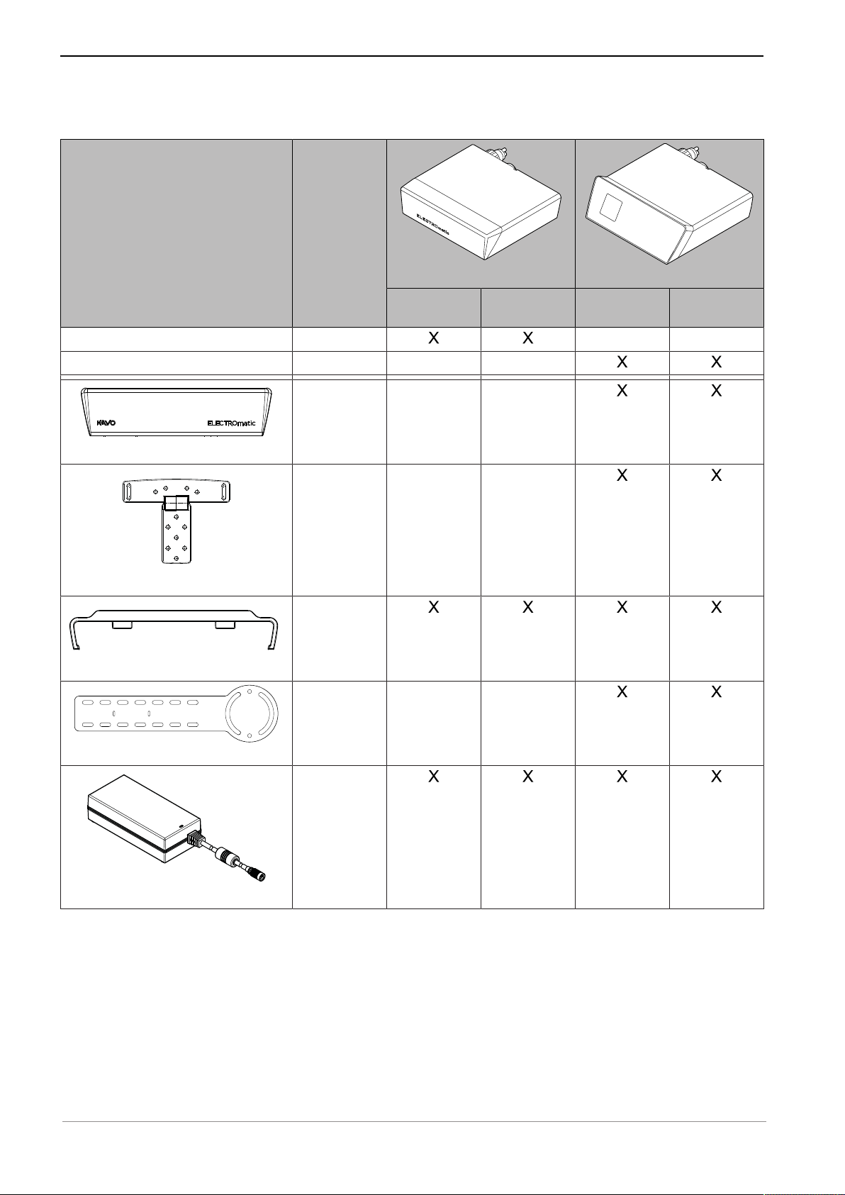
3.2 Scope of delivery
Figure Catalog
number
Control unit 1.011.1800
Control unit 1.011.1900
1.011.8054
Cover panel
1.011.7165
Mounting bracket
1.011.7168
Insert holder
1.011.8106
ELECTROmatic M/C
ELECTROmatic M
ELECTROmatic C
ELECTROmatic PM/PC
ELECTROmatic PM
ELECTROmatic PC
Mounting plate
Power supply type 4882
1.005.0120
18 / 80
Page 19

Figure Catalog
number
Instructions for use ELECTROmatic M/C and PM/PC
3 Product description | 3.2 Scope of delivery
Power cable (country-specific)
INTRA LUX Motor KL 703 LED
1.002.6861
US
0.223.4142
EU
0.692.6901
UK
0.692.6851
AU
1.013.2293
BR
1.004.3850
CN
0.692.6881
CH
1.007.0150
KL Motor
hose 1750
1.011.7200
or
KL Motor
hose 2200
1.011.5668
ELECTROmatic M/C
ELECTROmatic M
ELECTROmatic C
ELECTROmatic PM/PC
ELECTROmatic PM
ELECTROmatic PC
KL Motor hose 1750/2200
COMFORTbase 1750/2200
COMFORTbase 1750
1.011.7335
or
COMFORTbase 2200
1.011.7076
19 / 80
Page 20
Instructions for use ELECTROmatic M/C and PM/PC
3 Product description | 3.2 Scope of delivery
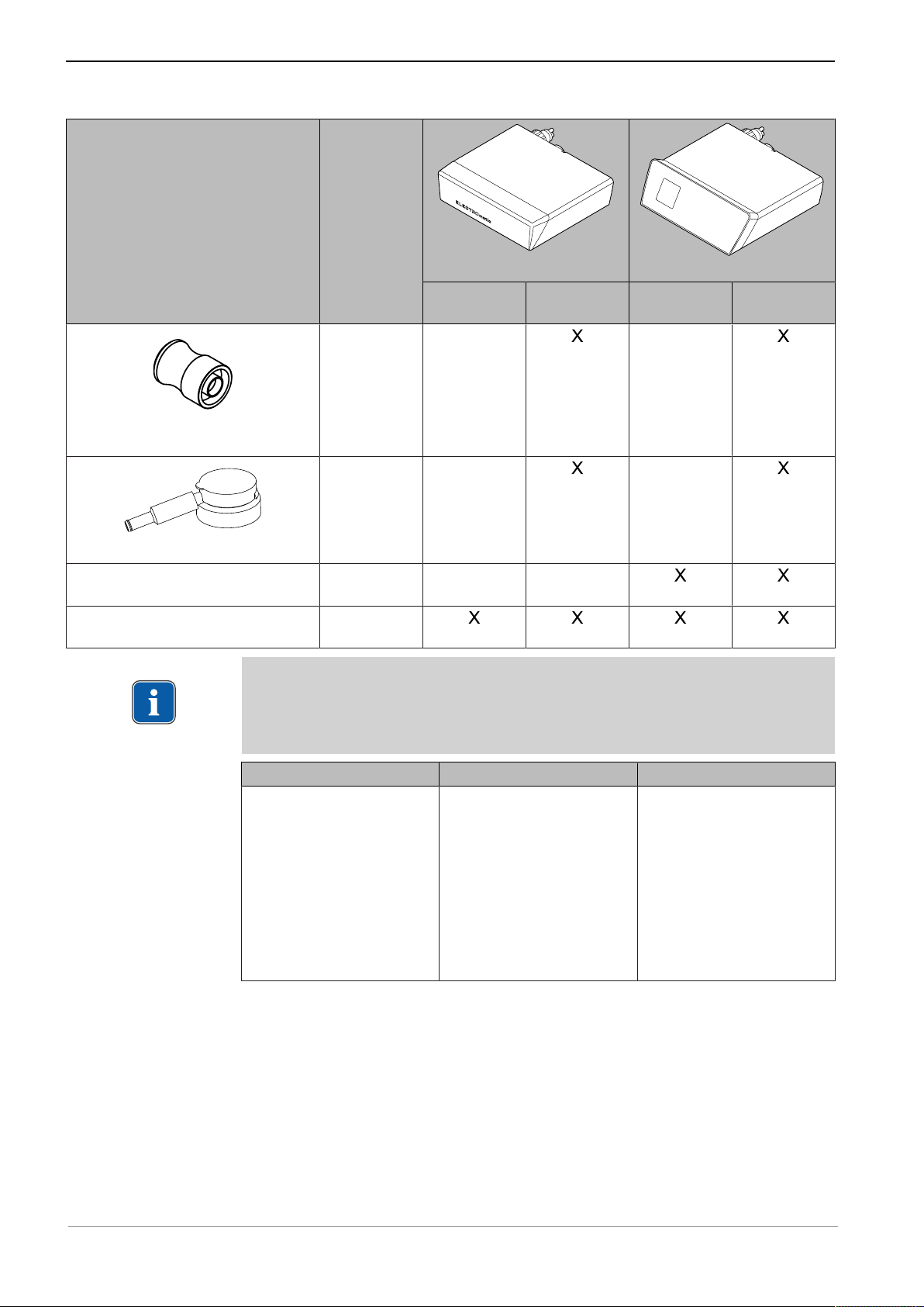
Figure Catalog
number
Germ reduction attachment for COMFORTdrive
Spray head for COMFORTdrive
Short instructions for use
ELECTROmatic PM/PC
Assembly instructions
ELECTROmatic
Note
Use exclusively the power cables and mains plugs approved in the specific
country. Use exclusively the power cables and mains plugs with the electrical
nominal data as listed in the following table.
1.006.5370
1.005.3154
1.012.9291
1.013.0312
ELECTROmatic M/C
ELECTROmatic M
ELECTROmatic C
ELECTROmatic PM/PC
ELECTROmatic PM
ELECTROmatic PC
Power cable Mains plug IEC coupler
▪ 3 x 18 AWG
▪ 60 oC / 140 oF
▪ 300 V
▪ black
▪ Style SJT
▪ Plug Hospital Grade
▪ NEMA 5 - 15
▪ Norm UL 498, CSA
▪ EN 60320 / C13
▪ 10 A
▪ 250 VAC
▪ black or transparent
C22.2 no 42
▪ black or transparent
▪ Marking ZJCZ.E41542
oder ZJCZ+CSA oder
ELBZ2/8
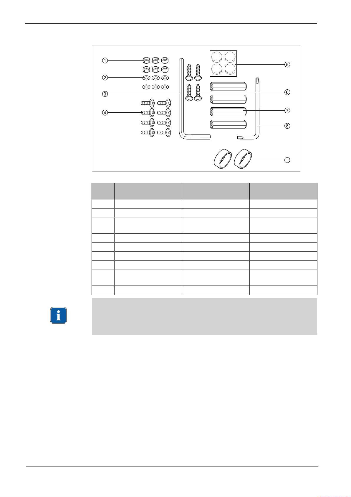
The installation set is part of the scope of delivery of all versions and consists of
the following parts:
20 / 80
Page 21
Instructions for use ELECTROmatic M/C and PM/PC
9
3 Product description | 3.2 Scope of delivery
ELECTROmatic installation set (Mat. no. 1.012.1883)
Pos.
Mat. No. Description Number
no.
① 0.251.5804 Hexagonal nuts M4 6
② 0.242.4012 Washers 6
③ 1.004.1568 Offset screwdriver
1
SW5
④ 1.012.0213 Screws M4x12 8
⑤ 0.220.0441 Pad 4
⑥ 1.012.0184 Screws 4x14 4
⑦ 1.012.1999 Spacer bolt, 35 mm 4
⑧ 1.012.1853 Offset screwdriver Torx
1
T20
⑨ 1.007.9736 Filter insert 2
Note
The pads enclosed in the installation set can be attached to the underside of
the device, if needed. The purpose of the pads is to prevent the device from
slipping.
See also:
2 4.6 Installation position 3: Mount on a holder or on the backside of a holder,
Page 38
21 / 80
Page 22
Instructions for use ELECTROmatic M/C and PM/PC
ELECTROmatic M/CELECTROmatic PM/PC
2
1
3
2
1
3
4
5
3 Product description | 3.3 ELECTROmatic – Versions
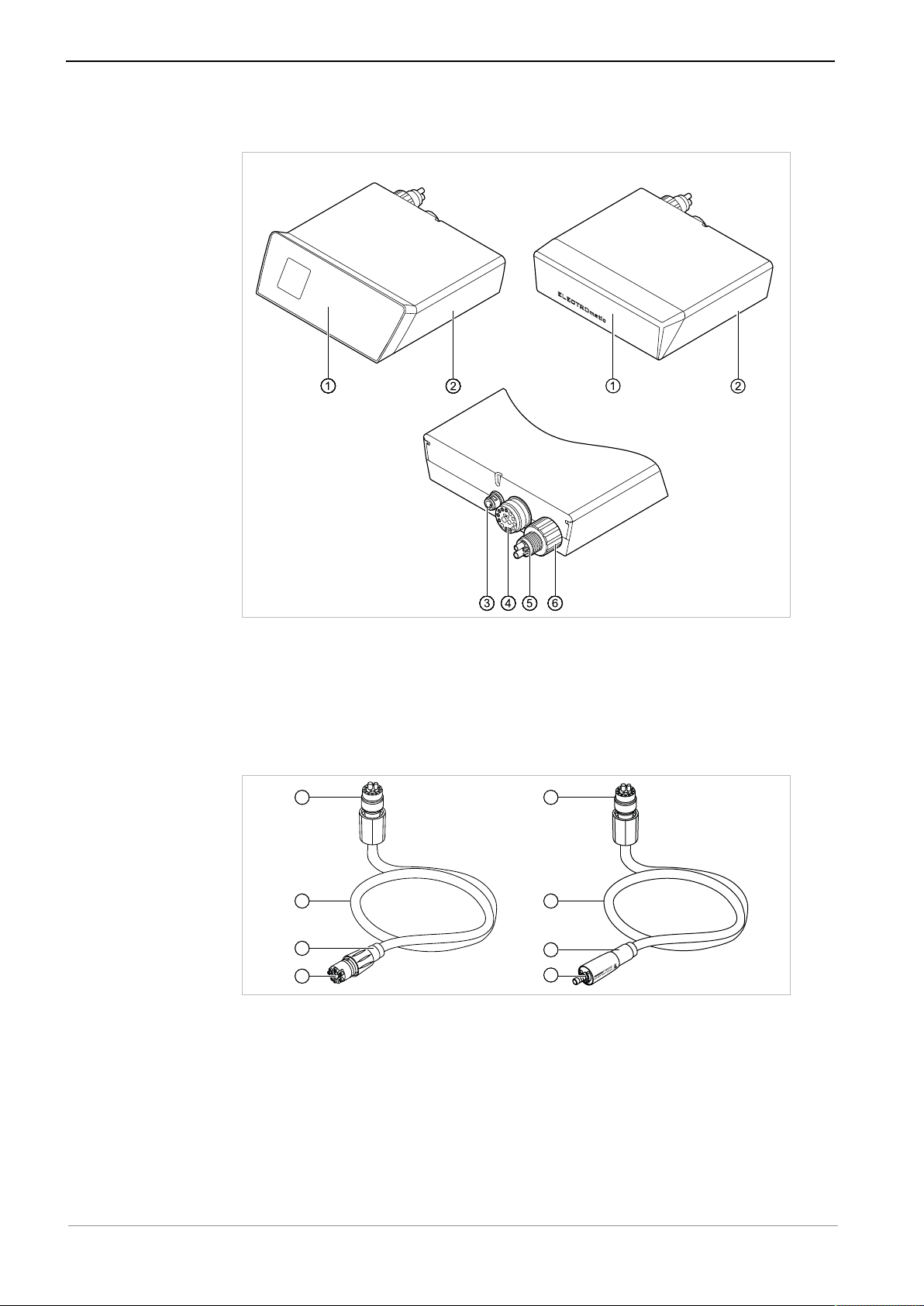
3.3 ELECTROmatic – Versions
ELECTROmatic Front and rear of the device
① Control panel/cover panel ④ Motor hose connector
② Control unit ⑤ 4-hole standard connection
③ Power supply connector ⑥ Water filter, replaceable
3.4 Motor hose
KL motor hose/COMFORTbase
① Connector for ELECTROmatic ④ Connector for motor
② KL motor hose 1750/2200 /
COMFORTbase 1750/2200
③ Spray regulation
⑤ Connector for COMFORTdrive
22 / 80
Page 23

Instructions for use ELECTROmatic M/C and PM/PC
5
4
3
2
1
3
2
1
5
4
3 Product description | 3.5 Control panel (PM/PC only)
3.5 Control panel (PM/PC only)
Note
The ELECTROmatic M/C versions of the product have no control panel. An
LED on the rear of the device flashes when the ELECTROmatic M/C is ready
for use.
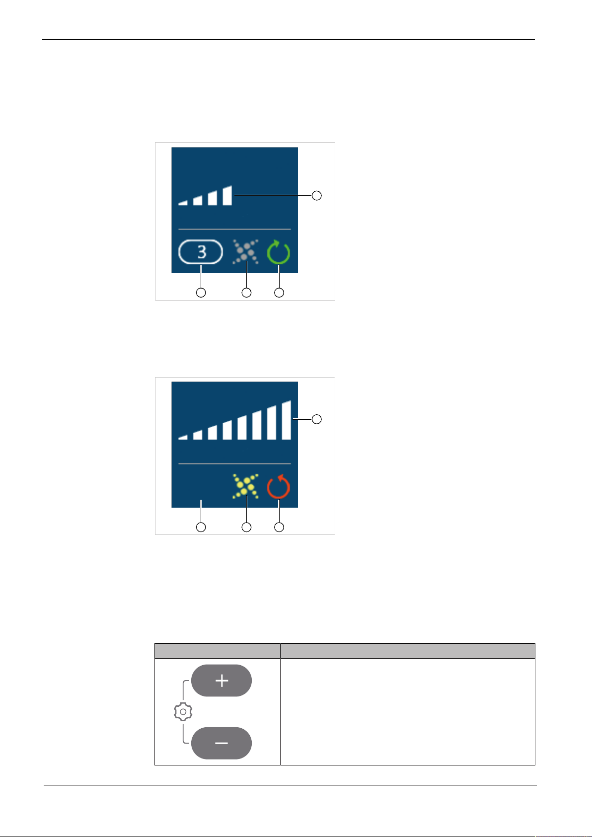
Control panel ELECTROmatic PM/PC
Display information ELECTROmatic PM/PC
Display information example 1
① Speed memory 1 ④ Speed factor and unit
② SAFEdrive active = yellow ⑤ Speed
③ Clockwise rotation = green
Display information example 2
① Speed memory 2 ④ Speed factor and unit
② SAFEdrive inactive = grey ⑤ Speed
③ Counterclockwise rotation = red
23 / 80
Page 24
Instructions for use ELECTROmatic M/C and PM/PC
4
3
2
1
3
2
1
4
3 Product description | 3.5 Control panel (PM/PC only)
If the speed display is set to "analog", the speed is displayed in analog manner
when the motor is running. When the motor is at rest, the maximum set speed
is shown digitally and the display switches to analog only when the foot control
is pressed, i.e. when the motor is started up.
Display information example 3
① Speed memory 3 ③ Clockwise rotation = green
② SAFEdrive inactive = grey ④ Analog speed display (approxi-
mately 50% of set maximum
speed)
Display information example 4
① No speed memory selected ③ Counterclockwise rotation = red
② SAFEdrive active = yellow ④ Analog speed display (100% of set
maximum speed)
Function of the operating keys of the ELECTROmatic
PM/PC
Key Function
▶ Press both the plus and minus key for 2 seconds
to start the "Settings" menu.
24 / 80
Page 25

Instructions for use ELECTROmatic M/C and PM/PC
3 Product description | 3.6 Technical specifications of the ELECTROmatic
Key Function
▶ Press the Plus key to increase a value.
▶ Press the Minus key to decrease a value.
Key is assigned doubly:
▶ Press the key to switch between clockwise and
counterclockwise rotation.
Requirement
"Settings" menu is active:
▶ Press key to select a parameter.
Key is assigned doubly:
▶ Press key to select speed memory 1.
See also:
2 6.4 Changing the speed setting, Page 58
Requirement
"Settings" menu is active:
▶ Press key to select a parameter.
▶ Press key to select speed memory 2.
See also:
2 6.4 Changing the speed setting, Page 58
▶ Press key to select speed memory 3.
See also:
2 6.4 Changing the speed setting, Page 58
3.6 Technical specifications of the ELECTROmatic
Dimensions of the package
Length 472 mm / 18.58"
Width 190 mm / 7.48"
Height 113 mm / 4.45"
Dimensions and weight of the control unit
Device version
M/C 143/5.63 118/4.65 36/1.42 331/11.68
PM/PC 145/5.71 132/5.2 44/1.73 381/13.44
Width in
mm/inch
Depth in
mm/inch
Height in
mm/inch
Weight in g/
ounces
Requirements
Protection class IP 30
25 / 80
Page 26

Instructions for use ELECTROmatic M/C and PM/PC
3 Product description | 3.6 Technical specifications of the ELECTROmatic
Ambient conditions
Permissible installation sites Indoor use
Permissible ambient temperature
range
Maximum relative humidity 80 % at 31 oC / 88 oF
Maximum relative humidity linearly decreasing 50 % at 40 o /
Pollution degree 2
Permissible up to 3,000 m / 9843 feet altitude
Air pressure 700 to 1060 hPa
+10oC to +35oC / 50oF to 95oF
104 oF
Transportation and storage conditions
Permissible ambient temperature
range
Permissible up to a maximum humidity of
Air pressure 700 to 1060 hPa
-20oC to +50oC / -4oF to +122oF
5 to 90 % non-condensing
Mode: intermittent operation
Operating time 0.5 minutes
Pause time 9 minutes
▶ Do not exceed the threshold load of the motor of 0.5 minutes operating
time / 9 minutes pause.
Note
In practical application, pulse loads lasting seconds or pause times lasting
seconds or minutes are realistic, usually without reaching the maximally possible motor current. This corresponds to the common working procedure of
dentists.
Note
If a handpiece is defective, the treatment time might be less than 30 seconds
due to the SAFEdrive function (automatic motor shut-off).
See also:
2 6.6 Protection function SAFEdrive (PM/PC only), Page 58
26 / 80
Page 27

3 Product description | 3.6 Technical specifications of the ELECTROmatic
Media options
Instructions for use ELECTROmatic M/C and PM/PC
Water quality according to DIN EN
Tap water
7494-2
Water hardness 8.4 to 12 °dH
pH 7.2 to 7.8
System pressure 1.8 to 5 bar / 26 to 72.5 psi
Spray air 1.0 to 2.5 bar / 14.5 to 36.2 psi
Spray water 0.8 to 2.0 bar / 11.6 to 29 psi
Cooling air exit at the motor coupling 6 to 9 Nl/min
Air filter 50 micrograms
Customer-provided water filtering 80 µm
Ideal settings at the dental unit
System pressure 3 bar / 43.5 psi
Spray air pressure
Spray water pressure
1)
pressure measured at the motor coupling using a pressure gauge Mat. no.
1.003.1050.
1)
1)
1 bar / 14.5 psi
0.8 bar / 11.6 psi
Speed
Speed range of the Motor KL 703 100 - 40,000 min-1 (rpm)
Speed range of the
20,000 - 200,000 min-1 (rpm)
COMFORTdrive 200 XDR
Motor torque
Maximum torque of the
Motor KL 703
Torque of the Motor KL 703 minimum
Maximum torque
COMFORTdrive 200 XDR
3 Ncm
0.15 Ncm
0.4 Ncm
Electrical ratings
Input voltage 36 V DC
Power 120 W
27 / 80
Page 28

Instructions for use ELECTROmatic M/C and PM/PC
3 Product description | 3.7 Symbols on product and rating plate
Motor cords
Cable lengths,
depends on ordered version|
1.75 m / 2.20 m (69" / 87")
3.7 Symbols on product and rating plate
The rating plates are affixed to the underside of the unit.
Accompanying documents
Please note the instructions for use
Please note the instructions for use
Please note the electronic instructions for use
HIBC Code
Certification
CE mark (Communauté Européenne)
VDE mark
MET mark
GOST R certification
EAC conformity mark (Eurasian Conformity = Eurasische Konformität)
Product characteristics
Manufacturer
Type Device type
Serial number
Catalog number
Type B applied part
28 / 80
Page 29

Instructions for use ELECTROmatic M/C and PM/PC
3 Product description | 3.8 Power supply type 4882
Supply voltage
Operating mode: continuous operation with intermittent load
Protection class II
Do not dispose of with household waste
3.8 Power supply type 4882
① Mains connection ③ Connecting cord
② Standby LED display
3.9 Technical data for the power supply type 4882
Note
The connection of the power supply must comply with the country-specific
regulations and requirements for medical devices.
Dimensions and weight
Width 160 mm/6.3 "
Height 44 mm/1.7 "
Depth 76 mm/3 "
Weight 0.78 kg /27.51 ounces
Length of connection cable 4.5 m / 177"
29 / 80
Page 30

Instructions for use ELECTROmatic M/C and PM/PC
3 Product description | 3.10 Symbols on the nameplate of the type 4882 power supply
Electrical ratings
Supply voltage 100 to 240 V AC, 47 to 63 Hz
Output voltage 36 V DC
Power 120 W
Current 3.34 A
Overvoltage category II
Mains voltage fluctuations ± 10 %
Requirements
Protection class I
Protection class IP 40
Environmental conditions
Permissible installation sites Indoor use
Permissible ambient temperature
range
Relative humidity 10 to 95% RH non-condensing
Pollution degree 2
Permissible up to 3,000 m / 9843 feet altitude
Air pressure 700 to 1060 hPa
0oC to +40oC / 32oF to 104oF
Transportation and storage conditions
Ambient temperature -20 ℃ to +80 ℃ / -4 oF to 176 oF
Relative humidity 10 to 95% RH non-condensing
Air pressure 700 hPa to 1060 hPa
3.10 Symbols on the nameplate of the type 4882 power supply
The rating plate is located on the underside of the device.
Certification
TÜV Rheinland mark
UL mark for components for USA/Canada
CE mark
30 / 80
Page 31

Instructions for use ELECTROmatic M/C and PM/PC
3 Product description | 3.10 Symbols on the nameplate of the type 4882 power supply
Product characteristics
Manufacturer
Type Device type
Catalog number
IN-
Input data: voltage, frequency, current
PUT:
Output data: power, voltage, current
OUTPUT:
S/N: Serial number
Manufacturing date
WEEK
:
Do not dispose of with household waste
31 / 80
Page 32

Instructions for use ELECTROmatic M/C and PM/PC
4 Installation | 4.1 Location
4 Installation
4.1 Location
Damage to the dentist element.
Installations involving an intervention on the dental unit might damage components, which can interfere with the safe function and cause injury.
▶ Have installations involving an intervention on the dental unit performed by
trained expert personnel only.
▶ Have the treatment center subjected to a safety check after installation.
Power supply and cords/hoses are on the floor.
Slipping and tripping.
▶ Power supply and cord/hoses need to be set-up/routed appropriately such
that they are not on the floor.
CAUTION
CAUTION
Note
To completely disconnect the device from the mains, the mains plug must be
pulled. For this reason, the unit must be set-up appropriately such that the
mains plug and the electrical outlet are easily accessible.
Note
Mind the electrical cord of the power supply! Route all cords appropriately
such that they do not get squashed, clamped or have a chair rolling over
them.
Note
Use the power supply in dry environments exclusively. Make sure that the
power supply is protected from the ingress of liquids.
▶ Place the product in an easily accessible place and visible for diagnostic pur-
poses.
4.2 Installation positions
There is a wide range of installation options for the ELECTROmatic. This overview makes no claim of being comprehensive. If possible, the installation
should be done without modification of the dentist element and/or existing attachment options on the dentist element should be utilized.
The 4 basic installation positions on holders are described in the following:
▪ Installation position 1: Below a holder
▪ Installation position 2: On the side of a holder
▪ Installation position 3: On a holder or on the backside of a holder
▪ Installation position 4: Mount control panel as remote control
32 / 80
Page 33

Instructions for use ELECTROmatic M/C and PM/PC
4 Installation | 4.2 Installation positions
Below a holder with insert
holder
Install control panel on
holder as remote control
On the side of a holder On a holder
Install control panel on
cabinet/wall as remote
control
Optional: Install control panel as remote control (PM/PC
only)
All installation positions afford the opportunity to install the ELECTROmatic in
two separate parts: The control panel as a remote control and the control unit
in two different installation positions.
For this purpose, the control panel must be disconnected from the control unit.
See also:
2 4.7.1 Disconnect the control panel from the control unit and install it on the
mounting bracket, Page 40
The control panel is connected to the control unit by a standard telephone cable
of 80 cm in length.
33 / 80
Page 34

Instructions for use ELECTROmatic M/C and PM/PC
9
4 Installation | 4.3 Preparing the installation
4.3 Preparing the installation
Insert holder
Mounting plate
Mounting bracket
Cover panel
ELECTROmatic installation set (Mat. no. 1.012.1883)
▶ Keep the installation set handy.
▶ For the parts from the scope of delivery required for each installation, see
list in the respective installation chapter.
▶ If needed, keep a suitable tool for shortening the mounting plate handy.
Note
If a larger gap needs to be bridged for installation, larger spacer bolts ⑦ from
commercial electronics supplies can be used.
▶ Connect the motor hose to the ELECTROmatic.
▶ Connect motor to motor hose.
See also:
2 5.1.3 Connecting the motor, Page 49
▶ Check to make sure that the motor is seated firmly in the holder of the
treatment unit.
4.4 Installation position 1: Mount below a holder
Below a holder with insert holder
34 / 80
Page 35

Instructions for use ELECTROmatic M/C and PM/PC
1
4
4
4
8
1
4
4 Installation | 4.4 Installation position 1: Mount below a holder
CAUTION
Damage to the dentist element.
Installations involving an intervention on the dental unit might damage components, which can interfere with the safe function and cause injury.
▶ Have installations involving an intervention on the dental unit performed by
trained expert personnel only.
▶ Have the treatment center subjected to a safety check after installation.
▶ Use the insert holder as a template for the screw positions on the underside
of the holder. If possible, use existing screws or perforations as screw positions.
Installation variant a)
The following parts from the scope of delivery and the installation set are required:
▪ 1x Insert holder
▪ 4x Screws M4x12 ④ with self-locking nuts ①
▪ 4x Washers ②
▶ Use 4 screws ④ and 4 washers ② to screw the insert holder to the holder
and fasten it using the 4 nuts ①.
Installation variant b)
The following parts from the scope of delivery and the installation set are required:
▪ 1x Insert holder
▪ 8x Screws M4x12 ④
▪ 4x Spacer bolts, 35 mm ⑦
▶ Use 8 screws to mount the spacer bolts ⑦ or larger commercial spacer bolts
(electronics supplies) between the insert holder and the lower edge of the
holder to increase the distance between the holder and the insert holder, if
applicable.
35 / 80
Page 36

Instructions for use ELECTROmatic M/C and PM/PC
4
4
4
1
4 Installation | 4.5 Installation position 2: Mount on the side of a holder
Installation variant c)
The following parts from the scope of delivery and the installation set are required:
▪ 1x Insert holder
▪ 4x Screws M4x12 ④ with self-locking nuts ①
▪ 4x Washers ②
▪ 1x Mounting plate
▶ To increase the distance between the holder and the insert holder, if appli-
cable, chamfer the mounting plate twice (U-shape) and use it for a spacer.
▶ Make sure that the insert holder is firmly seated.
▶ Slide the control unit of the ELECTROmatic into the insert holder.
4.5 Installation position 2: Mount on the side of a holder
CAUTION
Damage to the dentist element.
Installations involving an intervention on the dental unit might damage components, which can interfere with the safe function and cause injury.
▶ Have installations involving an intervention on the dental unit performed by
trained expert personnel only.
▶ Have the treatment center subjected to a safety check after installation.
The following parts from the scope of delivery and the installation set are required:
▪ 1x Mounting plate
▪ 4x Screws M4x12 ④ with self-locking nuts ①
36 / 80
Page 37

Instructions for use ELECTROmatic M/C and PM/PC
4 Installation | 4.5 Installation position 2: Mount on the side of a holder
▪ 4x Washers ②
▪ 2x Plastic screws ⑥ for fastening to the mounting plate
▶ Shorten the mounting plate with a suitable tool, if needed.
▶ Select the position of the mounting plate. If possible, use existing screws or
perforations as screw positions.
▶ Screw the ELECTROmatic to the round side of the mounting plate using 2
plastic screws ⑥ tightening the screws only lightly.
▶ Use the 4 screws ④ and 4 washers ② to screw the mounting plate to the
holder and secure it with the 4 nuts ①.
▶ Align the ELECTROmatic in its final ergonomic position and screw it to the
mounting plate such as to be hand-tightened.
37 / 80
Page 38

Instructions for use ELECTROmatic M/C and PM/PC
4 Installation | 4.6 Installation position 3: Mount on a holder or on the backside of a holder
4.6 Installation position 3: Mount on a holder or on the backside of a holder
On a holder
CAUTION
Damage to the dentist element.
Installations involving an intervention on the dental unit might damage components, which can interfere with the safe function and cause injury.
▶ Have installations involving an intervention on the dental unit performed by
trained expert personnel only.
▶ Have the treatment center subjected to a safety check after installation.
▶ Use the control unit as a template for the screw positions on a holder or on
the backside of a holder. If possible, use existing screws or perforations as
screw positions.
Installation variant a)
The following parts from the scope of delivery and the installation set are required:
▪ 1x Mounting bracket
▪ 2x Screws M4x12 ④ with self-locking nuts ①
▪ 2x Washers ②
▪ 2x Plastic screws
▶ Use 2 plastic screws to screw the mounting bracket to the control panel.
▶ Fold the mounting bracket and fasten it to the holder using 2 screws, 2
washers and 2 self-locking nuts.
38 / 80
Page 39

Instructions for use ELECTROmatic M/C and PM/PC
2
4 Installation | 4.6 Installation position 3: Mount on a holder or on the backside of a holder
Installation variant b)
The following parts from the scope of delivery and the installation set are required:
▪ 2x Screws
▶ Use screws to screw the control unit directly to the holder.
Installation variant c)
The following parts are needed:
▪ Double-sided adhesive tape
▶ Stick pads in the 4 recesses on the underside of the device and then set up
the control unit.
ð The pads keep the control unit from slipping.
39 / 80
Page 40

Instructions for use ELECTROmatic M/C and PM/PC
4 Installation | 4.7 Installation position 4: Mount control panel as remote control (PM/PC only)
4.7 Installation position 4: Mount control panel as remote control (PM/PC only)
4.7.1 Disconnect the control panel from the control unit and install it on the mounting bracket
▶ To detach the control panel from the control unit, unscrew 2 screws on the
underside of the device.
▶ Pull the control panel off the control unit.
▶ Break out one of the 4 cable feed-throughs on the inside of the cover panel.
▶ Guide the connecting cable of the control unit through this opening to the
control panel.
▶ Hold the cover panel to the position of the control panel and tighten the 2
screws on the underside of the device again.
40 / 80
Page 41

Instructions for use ELECTROmatic M/C and PM/PC
4 Installation | 4.7 Installation position 4: Mount control panel as remote control (PM/PC only)
▶ If required, break out the cable feed-through on the control panel.
▶ Guide the connecting cable of the control unit through this opening to the
control panel.
▶ Use 2 plastic screws to screw the control panel to the mounting bracket
such as to be hand-tightened.
▶ Define the position for the control unit and check the length of the standard
telephone cable.
▶ Mount the control unit.
See also:
2 4.4 Installation position 1: Mount below a holder, Page 34
The following chapters describe the installation of the control panel at the different installation positions.
41 / 80
Page 42

Instructions for use ELECTROmatic M/C and PM/PC
4 Installation | 4.7 Installation position 4: Mount control panel as remote control (PM/PC only)
4.7.2 Mount control panel on a holder / on the backside of a holder
CAUTION
Damage to the dentist element.
Installations involving an intervention on the dental unit might damage components, which can interfere with the safe function and cause injury.
▶ Have installations involving an intervention on the dental unit performed by
trained expert personnel only.
▶ Have the treatment center subjected to a safety check after installation.
The following parts from the scope of delivery and the installation set are required:
▪ 1x Insert holder
▪ 1x Mounting bracket
▪ 1x Cover panel
▪ 4x + 2x Screws M4x12 ④ with self-locking nuts ①
▪ 4x + 2x Washers ②
▪ Optional: 4x Spacer bolts, 35 mm ⑦
▪ Optional: 1x Mounting plate
▪ 2x Plastic screws ⑥
▶ Define the position of the control panel on the holder or on the rear of the
holder and draw a hole pattern for attachment. If possible, use existing
screws or perforations as screw positions.
▶ Drill the holes.
▶ Screw the mounting bracket with control panel to the holder or to the rear
of the holder using the 2 screws ④, washers ② and nuts ①.
42 / 80
Page 43

Instructions for use ELECTROmatic M/C and PM/PC
4 Installation | 4.7 Installation position 4: Mount control panel as remote control (PM/PC only)
▶ Mount the control unit.
See also:
2 4.4 Install below the dentist element, a holder or a cabinet, Page 34
4.7.3 Mount control panel on the side of a holder
CAUTION
Damage to the dentist element.
Installations involving an intervention on the dental unit might damage components, which can interfere with the safe function and cause injury.
▶ Have installations involving an intervention on the dental unit performed by
trained expert personnel only.
▶ Have the treatment center subjected to a safety check after installation.
Installation variant a)
The following parts from the scope of delivery and the installation set are required:
▪ 1x Mounting plate
▪ 1x Mounting bracket
▪ 1x Cover panel
▪ 4x Screws M4x12 ④ with self-locking nuts ①
▪ 4x Washers ②
▪ 2x Plastic screws ⑥ for fastening to the mounting plate
▶ Shorten the mounting plate with a suitable tool, if needed.
▶ Select the position of the mounting plate. If possible, use existing screws or
perforations as screw positions.
43 / 80
Page 44

Instructions for use ELECTROmatic M/C and PM/PC
4 Installation | 4.7 Installation position 4: Mount control panel as remote control (PM/PC only)
▶ Mark the attachment points and drill the holes on the holder.
▶ Screw the mounting bracket with control panel to the round side of the
mounting plate using the plastic screws ⑥ tightening the screws only
lightly.
▶ Use the 4 screws ④ and the washers ② to screw the mounting plate to the
holder and secure it with the nuts ①.
▶ Align the ELECTROmatic in its final ergonomic position and screw it down
such as to be hand-tightened.
Installation variant b)
The following parts from the scope of delivery and the installation set are required:
▪ 1x Mounting bracket
▪ 1x Cover panel
▪ 2x Screws M4x12 ④ with self-locking nuts ①
▪ 2x Washers ②
▶ Mark the attachment points and drill the holes.
▶ Use the 2 screws ④ and washers ② to screw the mounting bracket with
control panel to the holder in upright orientation and secure it with the nuts
①.
▶ Align the ELECTROmatic in its final ergonomic position and screw it down
such as to be hand-tightened.
44 / 80
Page 45

Instructions for use ELECTROmatic M/C and PM/PC
4 Installation | 4.7 Installation position 4: Mount control panel as remote control (PM/PC only)
Installation variant c)
The following parts from the scope of delivery and the installation set are required:
▪ 1x Mounting bracket
▪ 1x Cover panel
▪ 2x Screws M4x12 ④ with self-locking nuts ①
▪ 2x Washers ②
▪ 2x Plastic screws ⑥, for fastening to the mounting bracket
▶ Use a suitable tool to shorten the mounting bracket to the size of the con-
trol panel.
▶ Use 2 plastic screws to screw the control panel to the mounting bracket
such as to be hand-tightened.
▶ Mark the attachment points and drill the holes.
▶ Use the 2 screws ④ and the washers ② to screw the mounting bracket with
control panel to the holder and secure it with the nuts ①.
▶ Align the ELECTROmatic in its final ergonomic position and screw it down
such as to be hand-tightened.
45 / 80
Page 46

Instructions for use ELECTROmatic M/C and PM/PC
4 Installation | 4.7 Installation position 4: Mount control panel as remote control (PM/PC only)
▶ Mount the control unit.
See also:
2 4.4 Installation position 1: Mount below a holder, Page 34
4.7.4 Mount control panel to cabinet/wall
Installation on a cabinet/wall
CAUTION
Damage to the dentist element.
Installations involving an intervention on the dental unit might damage components, which can interfere with the safe function and cause injury.
▶ Have installations involving an intervention on the dental unit performed by
trained expert personnel only.
▶ Have the treatment center subjected to a safety check after installation.
The following parts from the scope of delivery and the installation set are required:
▪ 1x Insert holder
▪ 1x Mounting bracket
▪ 1x Cover panel
46 / 80
Page 47

Instructions for use ELECTROmatic M/C and PM/PC
4 Installation | 4.8 Connect the ELECTROmatic
▪ 4x + 2x Screws M4x12 ④ with self-locking nuts ①
▪ 4x + 2x Washers ②
▪ Optional: 4x Spacer bolts, 35 mm ⑦
▪ Optional: 1x Mounting plate
▪ 2x Plastic screws ⑥
▶ Open the cabinet.
▶ Define the position of the control panel in the cabinet or on the wall and
draw a hole pattern for attachment. If possible, use existing screws or perforations as screw positions.
▶ Installation in a cabinet: Use 2 plastic screws to screw the control panel to
the cabinet.
▶ Installation on the wall: Use 2 screws ④ and washers ② to screw the
mounting bracket with control panel to the wall and secure it with the nuts
①.
▶ Mount the control unit.
See also:
2 4.4 Installation position 1: Mount below a holder, Page 34
4.8 Connect the ELECTROmatic
See also:
2 5.1.2 Connect the ELECTROmatic, Page 48
2 5.1.5 Connect the power supply, Page 50
4.9 Check the installation
▶ Check if the fastening is secure.
▶ Perform the startup.
See also:
2 5 Startup, Page 48
47 / 80
Page 48

Instructions for use ELECTROmatic M/C and PM/PC
5 Commissioning | 5.1 Connection
5 Commissioning
Note
The ELECTROmatic may be operated exclusively with the
INTRA LUX KL703 LED motor (Mat. no. 1.007.0150), the COMFORTdrive
motorized contra-angle handpiece and the type 4882 power supply.
5.1 Connection
5.1.1 Electrical operating conditions
Property damage due to incorrect pressures.
Property damage to motor or handpiece.
▶ Set the pressures according to the technical specifications.
Property damage due to bad media.
Property damage to motor or handpiece.
▶ Make sure that the compressed air is dry and free of dirt and oil according
to EN ISO 7494-2.
▶ Make sure that the pH of the water is between 7.2 and 7.8.
NOTICE
NOTICE
Note
If the water is hard (above 12 °dH), a water softening device based on an
ion-exchange procedure must be fitted.
Insufficient water hardness (below 8.4 °dH) can promote the growth of algae.
Note
If necessary, insert a filter, water trap or air dryer.
Air and water requirements according to DIN EN 7494-2
The compressed air must be free of oil, dirt, and contamination. If needed:
▪ Use a compressor with a dry air system.
▪ Include an upstream air filter (on the compressor), if applicable.
▪ Blow out the lines before connecting them.
5.1.2 Connecting the ELECTROmatic
NOTICE
Property damage due to soiled water lines.
Property damage to the product.
▶ Make sure that the water filter does not get clogged by soiled water.
▶ For this purpose, rinse the turbine hose for at least 1 minute before con-
necting its free end to the product in order to remove any soiled water from
the lines.
48 / 80
Page 49

Instructions for use ELECTROmatic M/C and PM/PC
5 Commissioning | 5.1 Connection
Note
The ELECTROmatic has an automatic spray air and spray water shut-off. The
automatic spray air and spray water shut-off prevents the following:
- Dripping of spray water after the motor is stopped
- Continuous exit of water/air through leaky treatment centers
▶ Connect the 4-hole, 5-hole or 6-hole turbine hose of the treatment unit to
the filter of the ELECTROmatic.
or
▶ If the turbine hose of the treatment unit has a 2-hole or 3-hole connector,
replace the turbine hose with a 4-hole, 5-hole or 6-hole turbine hose or use
a commercial adapter available from specialized dealers.
See also:
2 11 Accessories and consumables, Page 73
5.1.3 Connecting the motor
▶ Slightly wet the O-rings on the connection hose with KAVOspray.
▶ Connect the motor to the supply hose and twist.
ð The correct attachment position is attained automatically.
▶ Screw tight the hose-side union nut proceeding in the direction of the ar-
row.
49 / 80
Page 50

Instructions for use ELECTROmatic M/C and PM/PC
5 Commissioning | 5.1 Connection
5.1.4 Connect the motor cord
▶ Plug the motor hose onto the motor hose connector on the rear of the
ELECTROmatic device and screw it tight.
▶ Set the spray regulation on the hose to maximum amount of water.
See also:
2 6.3 Regulating the spray water, Page 57
5.1.5 Connect the power supply
CAUTION
Power supply and cords/hoses are on the floor.
Slipping and tripping.
▶ Power supply and cord/hoses need to be set-up/routed appropriately such
that they are not on the floor.
NOTICE
Property damage from non-approved power supply.
Property damage to the product.
▶ Operate the product with the type 4882 power supply (Mat. no.
1.005.0120) exclusively.
Note
The connection of the power supply must comply with the country-specific
regulations and requirements for medical devices.
Note
The power supply automatically adjusts to the available mains voltage.
Note
Grounding reliability can only be achieved when the equipment is connected
to an equivalent receptacle marked "Hospital Only" or "Hospital Grade".
Note
The protective earth conductor is used as functional earthing (FE) rather than
as protective earthing (PE).
Note
Use the power supply in dry environments exclusively. Make sure that the
power supply is protected from the ingress of liquids.
50 / 80
Page 51

Instructions for use ELECTROmatic M/C and PM/PC
5 Commissioning | 5.2 Calibrating the foot control
▶ Connect the type 4882 power supply to the socket of the ELECTROmatic.
▶ Connect the power cable first to the power supply and then to the supply
mains socket.
▶ Route the cables appropriately such that there is no kinking and, if possible
and permitted by the treatment unit, in the support arm.
▶ Affix the cord with cord ties and/or cord tape.
5.2 Calibrating the foot control
▶ Press the foot control down once as far as it will go (maximum pressure) in
order to calibrate the foot control.
ð This starts up the motor and the system calibrates automatically to the ex-
isting system pressure.
Automatic calibration of the foot control
The calibration is performed automatically during the first startup, when the
foot control is pressed for the first time.
Once the calibration of the foot control has been done once, the calibration to
the maximum system pressure takes place automatically in the background
during operation (automatic calibration).
Minor pressure fluctuations are balanced automatically in this process.
51 / 80
Page 52

Instructions for use ELECTROmatic M/C and PM/PC
5 Commissioning | 5.3 Measure cooling air quantity at motor coupling
5.3 Measure cooling air quantity at motor coupling
▶ Place the airflow measuring tube ① (Mat. no. 0.411.4441) on the motor.
▶ Press the foot control to start the motor.
▶ Adapt the system pressure of the treatment unit appropriately such that the
cooling airflow is 6 to 9 Nl/min (upper edge of sphere ②).
▶ Comply with the system pressure limits from the technical specifications for
media.
See also:
2 3.6 Technical specifications of the ELECTROmatic, Page 25
5.4 Making the device settings
▶ Press both the plus and minus key for 2 seconds to start the "Settings"
menu.
52 / 80
Page 53

Instructions for use ELECTROmatic M/C and PM/PC
5 Commissioning | 5.4 Making the device settings
▶ Press the arrow keys to select the various parameters.
▶ Press the Plus key to increase a value.
or
▶ Press the Minus key to decrease a value.
ð The settings are always saved instantaneously.
▶ Press both the plus key and the minus key for 2 seconds to exit from the
"Settings" menu.
The following device settings can be changed according to need and/or displayed when the device is being put into service.
Display information Setting
Displays the software versions.
Turning SAFEdrive on / off.
See also:
2 6.6 Protection function SAFEdrive (PM/PC only),
Page 58
The LUX brightness can be adjusted between 0 and
4. "0" means that the LUX light is switched off.
53 / 80
Page 54

Instructions for use ELECTROmatic M/C and PM/PC
5 Commissioning | 5.4 Making the device settings
Display information Setting
The LUX afterglow time of the straight or contra-angle handpiece can be adjusted between 0 and 9 seconds. "0" means that the LUX light does not afterglow.
The volume of the key tone can be adjusted between 1 and 3.
You can select from 3 different kinds of key tones.
Pressure display in psi and bar for checking the input
pressure of the turbine hose.
Alignment of display.
The display can be aligned accordingly depending on
its installation position.
54 / 80
Page 55

Display information Setting
Select from digital and analog speed display.
Reset the device to factory settings.
Restores the condition of the device at the time of
delivery.
Press the "Plus" key 2x to reset the device to factory
settings.
Instructions for use ELECTROmatic M/C and PM/PC
5 Commissioning | 5.4 Making the device settings
55 / 80
Page 56

Instructions for use ELECTROmatic M/C and PM/PC
6 Operation | 6.1 Switching the ELECTROmatic on/off
6 Operation
Growth of germs.
Infections.
▶ Before treating a patient, let the spray air and spray water exit for at least
20 seconds.
▶ Before the first start-up and after downtimes (weekends, holidays, vaca-
tions, etc.), the air and water lines must be purged and/or rinsed.
▶ The germ reduction of the ELECTROmatic must be carried out via the treat-
ment unit.
See also:
2 8 Processing steps in accordance with DIN EN ISO 17664, Page 63
Incorrectly set parameters.
Property damage from incorrect input values.
▶ Check all input values on the display before use.
CAUTION
NOTICE
NOTICE
Contaminated or moist compressed air at the compressed air connection.
Premature wear.
▶ Supply dry, clean and uncontaminated compressed air in accordance with
ISO 7494-2 only.
Note
Please note the transmission/reduction ratio of the attachment handpieces as
these have an impact on the displayed speed of the clamped tool.
6.1 Switching the ELECTROmatic on/off
The unit is ready for operation as soon as it is connected.
▶ To switch the product on, connect the device to the power circuit.
ð An LED on the rear of the ELECTROmatic M/C flashes.
ð The treatment parameters are displayed on the display of the
ELECTROmatic PM/PC:
▶ To switch the device off, unplug the unit from the mains.
ð The LED on the rear of the ELECTROmatic M/C is off.
56 / 80
Page 57

Instructions for use ELECTROmatic M/C and PM/PC
1
3
2
6 Operation | 6.2 Start the motor
Note
The power consumption on idling is so low that the device does not need to
be disconnected.
6.2 Start the motor
Note
The pressure to start the motor is 1 bar/14.5 psi.
The minimum operating pressure at 40,000 rpm is 1.8 bar/26 psi.
▶ Press the foot control until the motor starting pressure (1 bar / 14.5 psi) is
exceeded.
ð The motor/COMFORTdrive starts up.
▶ Push the foot control down as far as it will go.
ð The set maximum speed is reached.
▶ Press the foot control partly down in order to regulate the speed between
minimum and maximum speed.
6.3 Regulating the spray water
CAUTION
Hazard from insufficient amount of spray water.
Damage to the cog due to overheating.
▶ Make sure that the motor speed is appropriate for the preparation on hand.
▶ Use the requisite minimal amount of spray water.
▶ Rotate the regulating sleeve ② right or left to infinitely adjust the water
portion of the spray.
ð Regulating sleeve rotated all the way to the right ① = no water supplied
ð Regulating sleeve rotated all the way to the left ③ = maximum amount of
water
57 / 80
Page 58

Instructions for use ELECTROmatic M/C and PM/PC
6 Operation | 6.4 Changing the speed setting
6.4 Changing the speed setting
Note
In the ELECTROmatic M/C without display, the speed can be changed only
with the foot control of the treatment unit. If a foot control without steps is
actuated, the instrument is operated at the maximum motor speed of 40,000
min-1 (rpm).
To make sure that a certain speed is not exceeded and/or is maintained in
the ELECTROmatic M/C without display, a reducing contra-angle handpiece
needs to be used (e.g. EXPERTmatic LUX contra-angle handpiece E15 L,
MASTERmatic LUX M07 L or MASTERmatic LUX M29 L).
The user can set 3 speed memories and invoke by pressing the keys, "1", "2"
or "3".
The following factory settings a pre-selected as defaults for the speed memories:
Speed memory INTRA LUX KL 703 LED
1 3,000 20,000
2 20,000 160,000
3 40,000 200,000
[min-1/rpm]
COMFORTdrive 200 XDR
[min-1/rpm]
▶ Press the "1", "2" or "3" key.
ð The display shows the set speed (speed min
▶ Press the Plus or Minus key to change the saved value.
-1
x 1,000).
ð The display shows the speed.
▶ Press the "1", "2" or "3" key for more than 3 seconds to save the value in
the respective speed memory.
ð Speed memory "1", "2" or "3" flashes and an audio signal is issued.
ð The set value is being saved.
6.5 Changing the direction of rotation
▶ Press the "Direction of motor rotation" key.
ð The direction of motor rotation changes.
ð The symbol on the display indicates the direction of motor rotation.
6.6 Protection function SAFEdrive (PM/PC only)
WARNING
Use of incorrect straight and contra-angle handpieces.
Risk of burn injury or overheating.
▶ Use only original KaVo high-speed handpieces of the 25L, E25, M25, M05,
25LP, 25LPA, 25LPR, 25LCA series or the COMFORTdrive motorized contraangle handpiece.
58 / 80
Page 59

Instructions for use ELECTROmatic M/C and PM/PC
6 Operation | 6.6 Protection function SAFEdrive (PM/PC only)
WARNING
Deactivation of the SAFEdrive function.
Increased risk of burn injury or overheating due to defective high-speed handpieces.
▶ KaVo recommends to always activate the SAFEdrive function during any
dental treatment with high-speed handpieces or the COMFORTdrive.
Note
The SAFEdrive function is a monitoring function for detection of defective
high-speed handpieces. Defective high-speed handpieces can heat up
strongly during use due to additional friction, especially in the head region,
and possibly cause burn injuries. KaVo recommends to activate the
SAFEdrive function during treatments inside the oral cavity in order to reduce
the risk of burn injuries caused by defective high-speed handpieces.
Note
SAFEdrive is deactivated by default at the time of delivery.
SAFEdrive reduces the probability and damage upon overheating of defective or
poorly maintained handpieces thus minimizing the risk of burn injuries to the
patient.
SAFEdrive function:
Possible defects can be detected by continuous monitoring of the idling properties of the handpiece during its use.
If the protective function is triggered, the SAFEdrive initially reduces the motor
speed and then stops the motor altogether if the excessive load persists.
Note
SAFEdrive works only with KaVo high-speed handpieces of the 25L, E25,
M25, M05, 25LP, 25LPA, 25LPR, 25LCA series and the COMFORTdrive motorized contra-angle handpiece. Inadvertent triggering of the SAFEdrive function
cannot be excluded if handpieces made by other manufacturers are used.
6.6.1 Turning SAFEdrive on / off
The user can turn the SAFEdrive function on or off individually for the three
speed memories.
With regard to handpieces from third-party manufacturers, KaVo recommends
disabling the SAFEdrive function as the SAFEdrive protection function is effective only with high-speed handpieces from KaVo.
▶ Press both the plus and minus key for 2 seconds to start the "Settings"
menu.
▶ Press the arrow keys until the display shows "SAFEdrive".
59 / 80
Page 60

Instructions for use ELECTROmatic M/C and PM/PC
.......
6 Operation | 6.6 Protection function SAFEdrive (PM/PC only)
▶ Use the Plus and Minus keys to select the desired SAFEdrive combination
for the speed memory.
ð The settings are always saved instantaneously.
ð The activated speed memories are shown in blue.
ð All combinations for SAFEdrive are possible:
▶ Press both the plus key and the minus key for 2 seconds to exit from the
"Settings" menu.
6.6.2 Use with the SAFEdrive function
With regard to handpieces from third-party manufacturers, KaVo recommends
disabling the SAFEdrive function as the SAFEdrive protection function is effective only with high-speed handpieces from KaVo.
See also:
2 6.6.1 Turning SAFEdrive on / off, Page 59
If SAFEdrive is activated and the handpiece is overloaded, the first stage,
"SAFEdrive alert", is activated:
▪ The motor power is reduced (can lead to a drop in motor speed).
▪ The LUX light starts to pulse.
▪ The SAFEdrive icon is yellow and flashes.
Requirement
The handpiece is not defective
▶ If you use a handpiece from a third-party manufacturer, deactivate
SAFEdrive or use a high-speed handpiece from KaVo.
60 / 80
Page 61

Instructions for use ELECTROmatic M/C and PM/PC
6 Operation | 6.6 Protection function SAFEdrive (PM/PC only)
▶ If the SAFEdrive icon is yellow and flashes, relieve the handpiece of its load
for at least 2 seconds, i.e. lift it off the tooth.
ð The motor reaches maximum speed again and the SAFEdrive icon turns yel-
low again.
▶ As soon as the motor reaches maximum speed again and the SAFEdrive
icon turns yellow, continue working as usual making sure to use intermittent mode as the operating mode.
See also:
2 3.6 Technical specifications of the ELECTROmatic, Page 25
If the exposure to the load persists for more than 10 seconds, the stage,
"SAFEdrive error", is reached:
▪ The motor is stopped automatically.
▪ The SAFEdrive icon is red and flashes.
▶ If you use a handpiece from a third-party manufacturer, deactivate
SAFEdrive or use a high-speed handpiece from KaVo.
▶ If an automatic motor stop signals that the "SAFEdrive error" status is evi-
dent, remove the handpiece from the mouth of the patient and proceed as
follows:
▶ Carefully check the handpiece head for:
- Temperature
- Damage
- Ability to rotate the bur
▶ The motor can be restarted if there is no damage or overheating evident.
To do so, press the foot control again.
▶ When you continue working make sure not to touch the cheek with the
handpiece head and, in particular, with the press-button.
▶ If damage or overheating is evident, replace the handpiece or have it re-
paired.
61 / 80
Page 62

Instructions for use ELECTROmatic M/C and PM/PC
7 Decommissioning | 7.1 Disconnecting the electrical connection
7 Decommissioning
7.1 Disconnecting the electrical connection
▶ To disconnect the power cable from the mains, unplug the connector of the
power supply from the supply mains socket.
▶ Unplug the power cable from the device.
7.2 Disconnecting the ELECTROmatic from the treatment unit
▶ Disconnect the 4-hole, 5-hole or 6-hole hose of the treatment unit from the
filter or the adapter of the 2-hole to 4-hole connector of the ELECTROmatic.
7.3 Unplugging the motor/COMFORTdrive
▶ Unplug the plug of the motor cord from the connector on the device. Make
sure to grasp the plug as close to the device as possible.
Note
Clean and disinfect the motor while it is connected to the motor cord.
See also:
2 Instructions for use INTRA LUX KL 703 LED / COMFORTdrive 200 XDR
62 / 80
Page 63

Instructions for use ELECTROmatic M/C and PM/PC
8 Processing steps in accordance with DIN EN ISO 17664 | 8.1 Cleaning
8 Processing steps in accordance with DIN EN ISO 17664
Note
The processing steps for the motor, the COMFORTdrive and the straight and
contra-angle handpieces are described in the corresponding instructions for
use.
NOTICE
Improper disinfection.
Property damage to the product.
▶ Do not immerse product in liquids.
▶ Use disinfectant in accordance with the instructions of the manufacturer.
▶ No spray disinfection.
▶ Only disinfect by wiping.
▶ Never use chlorine-containing disinfectants.
Note
The processing instructions have been validated by the manufacturer. Any
departure from the instructions provided must be checked by the processing
entity for efficacy and possible detrimental consequences.
8.1 Cleaning
Note
Do not use solvents or aggressive chemicals.
8.1.1 Preparation at the site of use
▶ Unplug the unit from the main power supply.
▶ Decontaminate as close as possible to use.
▶ Remove extensive soiling immediately after it occurs.
8.1.2 Manual external cleaning
Note
Do not use scouring cleansers.
▶ Make sure that the device is disconnected from the mains.
▶ Dampen a soft cloth with tap water or a mild cleaning solution (weak soapy
water).
▶ Wipe all external surfaces of the ELECTROmatic housing and the external
surfaces of the motor cord with the lightly dampened cloth.
8.1.3 Manual cleaning of the inside
There is no specific cleaning of the inside of the unit.
For protection from infection, it is recommended to rinse the water and air
ducts (coolant media) for at least 20 seconds before treating a patient.
63 / 80
Page 64

Instructions for use ELECTROmatic M/C and PM/PC
8 Processing steps in accordance with DIN EN ISO 17664 | 8.2 Disinfection
8.1.4 Mechanical cleaning of the exterior and interior
Not applicable.
8.2 Disinfection
CAUTION
Growth of germs.
Infections.
▶ Before treating a patient, let the spray air and spray water exit for at least
20 seconds.
▶ Before the first start-up and after downtimes (weekends, holidays, vaca-
tions, etc.), the air and water lines must be purged and/or rinsed.
▶ The germ reduction of the ELECTROmatic must be carried out via the treat-
ment unit.
KaVo recommends the following products for germ reduction of the spray water
of the treatment unit:
▪ KaVo Oxygenal 6 made by KaVo Dental GmbH www.kavo.com
▪ BluTab made by ConFirm Monitoring Systems Inc www.blutab.com
▪ ICX® Water Treatment Tablets made by A-dec
▶ Use in accordance with manufacturer specifications.
Note
The unit must be disinfected manually only.
8.2.1 Manual external disinfection
▶ Use a soft disposable cloth and an approved disinfectant for germ reduction
by wiping down all visible surfaces of the unit, foot control surfaces, and
connecting cables. Make sure that all surfaces are fully wetted.
▶ Let the disinfectant act for the prescribed time.
▶ Dry the surfaces.
Permissible disinfectants (application range in accordance with the available
manufacturer's instructions for use and national guidelines. Please note material
safety data sheets.) KaVo recommends the following products based on the
compatibility of the materials. The microbiological efficacy must be ensured by
the disinfectant manufacturer.
▪ FD 322 (Dürr)
▪ Microcide AF Liquid (Schülke & Mayr)
▪ CaviCide (Metrex)
▪ Incidin Liquid (Ecolab)
Note
Comply with the instructions for use of the disinfectant.
8.2.2 Manual disinfection of the interior
The germ reduction of the ELECTROmatic must be carried out via the treatment
unit.
64 / 80
Page 65

Instructions for use ELECTROmatic M/C and PM/PC
8 Processing steps in accordance with DIN EN ISO 17664 | 8.3 Packaging
▶ Connect the ELECTROmatic to the treatment unit.
▶ Follow the instructions for germ reduction of the treatment unit.
The product should be used according to the instructions of the manufacturer
and the Instructions for Use of the treatment unit.
8.2.3 Mechanical disinfection of the exterior and interior
The exterior and interior of this product are not designed for automated disinfection.
8.3 Packaging
Not applicable.
8.4 Sterilization
Not applicable.
8.5 Storage
Processed products must be stored, protected from bacteria, to the extent possible, and dust, in a dry, dark, cool room.
Note
Comply with the expiration date of the sterilized items.
8.6 Service, inspection and testing after processing
Note
It is essential to comply with the hygiene requirements (sterility) during the
test after processing. If sites of fracture and obvious changes of the surface
are visible, the parts need to be checked by the Service.
Check for cleanliness, intactness, servicing, and repair as described in the following:
▶ Check the adjustable functions of the unit and the motor function.
▶ Check the control commands on the foot control.
65 / 80
Page 66

Instructions for use ELECTROmatic M/C and PM/PC
1
9 Maintenance | 9.1 Changing the filter - water inlet
9 Maintenance
KaVo recommends that only original KaVo parts® be used for operating and repairs since their safety, operation and specific suitability have been tested in extensive tests.
Note
KaVo grants no guarantee of function and KaVo accepts no liability unless
original replacement parts and operating materials are used exclusively.
Note
The device must not be serviced or repaired during treatment/use.
The servicing work described in the following can be performed by the operator/user.
9.1 Changing the filter - water inlet
CAUTION
Hazard from insufficient amount of spray water.
Insufficient spray water can cause the medical device to overheat and damage
the tooth.
▶ Check and/or change the filter.
▶ Check the spray water channels and clean the spray nozzles with the nozzle
pin according to need.
KaVo recommends checking the filter every 3 months initially and to change the
filter insert according to need. The scope of delivery includes 2 filter inserts. After this time, the filter should be regularly checked and replaced according to
need with the interval being appropriate for the conditions at your practice and
the degree of soiling.
▶ Undo the union nut proceeding in the direction of the arrow.
▶ Replace the filter insert (Mat. no. 1.007.9736) ① if there is any visible
soiling.
66 / 80
Page 67

Instructions for use ELECTROmatic M/C and PM/PC
9 Maintenance | 9.2 Replacing the LED lamp of the KL 703 motor
▶ Clean the union nut and the surface of the filter insert.
▶ Tighten the union nut and check the filter for leakage.
9.2 Replacing the LED lamp of the KL 703 motor
CAUTION
Danger from hot lamp.
Risk of burn injury.
▶ Do not touch lamp after previous operation. Let the lamp cool off.
▶ Pull the sleeve off while twisting slightly.
▶ Push the old KaVo Mini LED lamp out of the mount with your fingernail and
remove it.
▶ Inset the new KaVo Mini LED lamp into the recess such that the contact
surfaces align with those of the mount. Slide the lamp into the mount. Place
the sleeve on the motor and pull it up.
Note
The KaVo Mini LED lamp is a semiconductor element and must be operated
with direct current only. The lamp must be inserted with the poles in the correct orientation for the lamp to work properly.
NOTICE
LED lamp inserted in wrong position/with wrong polarity.
Damage to or bending of the contacts.
▶ Make sure that position and polarity are correct.
Case 1: KaVo Mini LED lamp is on
Case 2: The KaVo Mini LED lamp is faint
- Increase the cold light intensity on the unit until the desired light intensity is
reached.
Case 3: KaVo Mini LED lamp is red or off
- Insert KaVo Mini LED lamp after rotating it 180° about its axis.
▶ Put the sleeve on while twisting it slightly.
67 / 80
Page 68

Instructions for use ELECTROmatic M/C and PM/PC
9 Maintenance | 9.3 Replacing the LED lamp of the COMFORTbase
9.3 Replacing the LED lamp of the COMFORTbase
The user may change the bulb.
Hot lamp.
Risk of burn injury.
▶ Wait for the lamp to cool down before replacing it.
▶ Slide the enclosed lamp changer on the MULTI LED and pull out the lamp in
axial direction.
▶ Insert the new lamp into the lamp changer, and introduce it into the hole in
the face of the supply hose. Carefully press the lamp into the socket.
▶ Carefully eject the lamp with the ejector.
CAUTION
Note
The KaVo MULTI LED bulb is a semiconductor element and may only be operated with direct current. To ensure proper function, the LED needs to be inserted with the correct polarity.
NOTICE
LED lamp inserted in wrong position/with wrong polarity.
Damage to or bending of the contacts.
▶ Make sure that position and polarity are correct.
The following may happen after you turn on the KaVo MULTI LED lamp:
▪ Case 1: KaVo MULTI LED lamp is on.
▪ Case 2: KaVo MULTI LED lamp is red or off.
- Take the KaVo MULTI LED lamp out of its mount as described above and
re-insert it after rotating it by 180° about its axis.
9.4 Replacing the motor hose
▶ If the motor hose is defective, disconnect the motor hose from the motor,
and unscrew it from and pull it off the rear of the ELECTROmatic device.
▶ Connect a new motor hose to the device and the motor.
See also:
2 5.1.4 Connect the motor cord, Page 50
2 5.1.3 Connect the motor, Page 49
68 / 80
Page 69

Instructions for use ELECTROmatic M/C and PM/PC
9 Maintenance | 9.4 Replacing the motor hose
▶ Dispose of the defective motor hose in appropriate manner.
69 / 80
Page 70

Instructions for use ELECTROmatic M/C and PM/PC
10 Troubleshooting
10 Troubleshooting
Note
The ELECTROmatic PM/PC displays error messages and/or instructions visually on its display.
The ELECTROmatic M/C displays error messages and/or instructions by
means of a flashing LED on the rear of the device. The error code is indicated
by how often the LED flashes, e.g. the LED flashes 7 times for error message
"E7".
The motor is shut off in any case of malfunction.
▶ If the error message does not disappear or the error is reported again, con-
tact Service.
▶ Restart the unit with all the other error messages.
Malfunction Cause Remedy
No or insufficient spray
water.
Device malfunctions
(no display, the LED on
the rear of the device
does not flash).
Spray water regulation
is closed.
Water line is soiled.
Filter insert is soiled.
Spray water on treatment unit or foot control is closed.
No voltage supply.
▶ Open the spray water fully.
See also:
2 6.3 Regulating the spray water, Page 57
▶ Open the spray water fully.
See also:
2 6.3 Regulating the spray water, Page 57
▶ Pull the handpiece off and actuate the spray
water in bursts (rinsing process).
▶ Replace filter on water inlet.
See also:
2 9.1 Changing the filter - water inlet, Page 66
▶ Open the spray on the treatment unit.
▶ If the error persists, unscrew the turbine hose
and check if there is any flow of water.
▶ If there is no flow of water, notify a service en-
gineer.
▶ Check/restore voltage supply and correct con-
nection.
ð The standby LED on the power supply is on.
See also:
2 3.8 Power supply type 4882, Page 29
▶ If the standby LED on the power supply is not
on, replace the power supply.
▶ If error persists, notify the service engineer.
Device malfunctions
(no display, the LED on
the rear of the device
flashes).
No voltage supply on
the control panel.
No connection to the
control panel.
▶ Check/restore correct connection.
▶ Replace the connection cable to the control
panel.
▶ Replace the control panel.
▶ If error persists, notify the service engineer.
70 / 80
Page 71

Instructions for use ELECTROmatic M/C and PM/PC
Malfunction Cause Remedy
10 Troubleshooting
Maximum speed not
reached.
Supply pressure
changed strongly.
Kink or leak in supply
hose.
Motor and/or handpiece
are sluggish.
LUX light is red. Incorrect LED poles.
LUX light is not on. LED is defective.
Motor hose is defective.
Device is defective.
SAFEdrive icon flashes
yellow.
SAFEdrive alert.
Motor is overloaded.
Also refer to: Chapter
on SAFEdrive Protection Function
▶ Repeatedly push the foot control down as far
as it will go.
ð The motor starts-up during this process. The
automatic calibration increases the speed continuously up to the maximum pressure.
▶ Remove the kink and check for damage!
▶ In case of damage/leakage, replace the supply
hose.
▶ If error persists, notify the service engineer.
▶ Replace or repair handpiece.
▶ If error persists, notify the service engineer.
▶ Rotate LED or replace it, if applicable.
▶ Replace the LED.
▶ If error persists, notify the service engineer.
▶ Replace motor hose.
▶ Replace the control unit.
▶ If error persists, notify the service engineer.
▶ If you use a handpiece from a third-party man-
ufacturer, deactivate SAFEdrive or use a highspeed handpiece from KaVo.
▶ If you use a high-speed handpiece from KaVo,
relieve the handpiece of its load for at least 2
seconds, i.e. lift it off the tooth.
▶ As soon as the motor reaches maximum speed
again and the SAFEdrive icon turns yellow,
continue working as usual making sure to use
intermittent mode as the operating mode.
SAFEdrive icon flashes
red.
SAFEdrive error.
The motor is stopped
automatically.
Motor is overloaded.
Also refer to: Chapter
on SAFEdrive Protection Function
71 / 80
See also:
2 3.6 Technical specifications of the ELECTRO-
matic, Page 25
2 6.6 Protection function SAFEdrive (PM/PC
only), Page 58
▶ If you use a handpiece from a third-party man-
ufacturer, deactivate SAFEdrive or use a highspeed handpiece from KaVo.
▶ If you use a high-speed handpiece from KaVo,
remove the handpiece from the mouth of the
patient and proceed as follows:
▶ Carefully check the handpiece head for:
- Temperature
- Damage
- Ease of operation
▶ The motor can be restarted if there is no dam-
age or overheating evident. To do so, press
the foot control again.
▶ Service the handpiece.
▶ If damage or overheating is evident, replace
the handpiece or have it repaired.
Page 72

Instructions for use ELECTROmatic M/C and PM/PC
10 Troubleshooting
Malfunction Cause Remedy
Event E2 Foot control is being
pressed during startup.
Event E3 No motor is connected.
Event E4 Motor is blocked.
Event E5 Automatic light and
motor shut-off during
continuous operation of
the motor.
Event E8 Saved data or settings
have been reset to
starting value.
Event E12 No connection to mo-
tor.
Event E14 Motor overload.
▶ Do not press the foot control when you switch
the unit on.
▶ Connect the motor.
▶ Relieve the motor of load, stop and start on
foot control.
▶ Comply with defined operating mode.
▶ Confirm message and check or correct the pro-
gram settings.
▶ If error persists, notify the service engineer.
▶ Check/restore correct connection.
▶ Replace the motor cord.
▶ If error persists, notify the service engineer.
▶ Relieve the motor of load, stop and start on
foot control.
All other events Internal system error.
▶ Turn the unit off and on.
▶ If error persists, notify the service engineer.
72 / 80
Page 73

Instructions for use ELECTROmatic M/C and PM/PC
11 Accessories and consumables
11 Accessories and consumables
Name Catalog number
Filter insert 1.007.9736
Airflow measuring tube 0.411.4441
Adaptor for the airflow measuring tube 1.005.1702
Motor INTRA LUX KL 703 LED 1.007.0150
KL Motor hose 1750 1.011.7200
KL Motor hose 2200 1.011.5668
COMFORTdrive 200 XDR 1.007.3570
COMFORTbase 1750 1.011.7335
COMFORTbase 2200 1.011.7076
Mini LED for INTRA LUX KL 703 LED
motor
KaVo MULTI LED lamp for
COMFORTbase
O-ring set 8.3x0.68 for INTRAmatic 0.200.6120
O-ring set 4.7x0.7 for COMFORTbase
coupling
O-ring 17x1 (KL motor) 1.003.5822
O-ring 17x0.8 (KL motor) 1.003.5656
KaVo straight and contra-angle hand-
pieces
1.007.8474
1.007.5372
1.005.0327
See KaVo INTRAmatic Handpiece Program
73 / 80
Page 74

Instructions for use ELECTROmatic M/C and PM/PC
12 Information on electromagnetic compatibility | 12.1 Guidelines and manufacturer's declaration - electromagnetic
emission
12 Information on electromagnetic compatibility
12.1 Guidelines and manufacturer's declaration electromagnetic emission
The ELECTROmatic is intended for use in an environment of the kind specified
below. The customer or user of the ELECTROmatic should make sure that the
device is used in an environment of the specified type.
Measurements of emitted interference
HF emissions according to EN
55011 (CISPR 11)
HF emissions according to EN
55011 (CISPR 11)
Emission of harmonics according
to IEC 61000-3-2
Emission of voltage fluctuations/
flicker according to IEC
61000-3-3
Conformance Electromagnetic environment
Guidelines
Group 1 The ELECTROmatic uses HF en-
ergy exclusively for its internal
functions. Therefore, the HF
emission of the device is very low
and interference with adjacent
electronic devices is unlikely.
Class B The ELECTROmatic is suitable for
use in all facilities, including residential facilities, and areas that
are directly connected to a public
supply mains that also supplies
buildings used for residential purposes.
Class A The ELECTROmatic is suitable for
use in all facilities, including residential facilities, and areas that
are directly connected to a public
supply mains that also supplies
buildings used for residential purposes.
Conforms The ELECTROmatic is suitable for
use in all facilities, including residential facilities, and areas that
are directly connected to a public
supply mains that also supplies
buildings used for residential purposes.
12.2 Guidelines and manufacturer's statement Electromagnetic immunity
The ELECTROmatic is intended for use in an environment of the kind specified
below. The customer or user of the ELECTROmatic should make sure that the
device is used in an environment of the specified type.
74 / 80
Page 75

Instructions for use ELECTROmatic M/C and PM/PC
12 Information on electromagnetic compatibility | 12.3 Guidelines and manufacturer's statement - Electromagnetic
immunity
Interference immunity tests
Electrostatic discharge
(ESD) according to
IEC 61000-4-2
Fast transient electrical interference /
bursts according to
IEC 61000-4-4
Surges according to
IEC 61000-4-5
Voltage interruptions,
short-term interruptions, and fluctuations
of the supply voltage
according to IEC
61000-4-11
Magnetic field at the
supply frequency
(50/60 Hz) according
to IEC 61000-4-8
IEC 60601 test levels
± 8 kV contact discharge
± 15 kV atmospheric
discharge
Compliance level Electromagnetic environment
- Guidelines
± 8 kV contact discharge
± 15 kV atmospheric
discharge
Floors should be made of wood
or concrete or be fitted with ceramic tiles. If the floor is fitted
with synthetic material, the relative humidity must be at least 30
%.
± 2 kV for power lines
± 2 kV for input and
output lines
± 2 kV for power lines
and input and output
lines
The quality of the supply voltage
should correspond to that of a
typical business or hospital environment.
± 1 kV push-pull voltage
± 2 kV common mode
voltage
0 % / 0.5 cycles
at 0º to 315º in 45º
increments
0 % / 1 cycle
70 % / 25 cycles
0 % / 250 cycles
± 1 kV push-pull voltage
± 2 kV common mode
voltage
0 % / 0.5 cycles
at 0º to 315º in 45º
increments
0 % / 1 cycle
70 % / 25 cycles
0 % / 250 cycles
The quality of the supply voltage
should correspond to that of a
typical business or hospital environment.
The quality of the supply voltage
should correspond to that of a
typical business or hospital environment.
30 A/m 30 A/m Magnetic fields at the mains fre-
quency should correspond to typical values in a business and hospital environment.
12.3 Guidelines and manufacturer's statement Electromagnetic immunity
The ELECTROmatic is intended for use in an environment of the kind specified
below. The customer or user of the ELECTROmatic should make sure that the
device is used in an environment of the specified type.
75 / 80
Page 76

Instructions for use ELECTROmatic M/C and PM/PC
P
P
12 Information on electromagnetic compatibility | 12.3 Guidelines and manufacturer's statement - Electromagnetic
immunity
Interference immunity tests
Wire-based HF interference according to
IEC 61000-4-6
Wireless HF interference according to IEC
61000-4-3
IEC 60601 test levels
3 V
eff
150 kHz to 80 MHz
outside ISM bands
3 V/m
80 MHz to 2700 MHz
Compliance level Electromagnetic environment
- Guidelines
3 V
eff
a
3 V/m
Handheld and mobile wireless
devices should not be used at a
shorter distance from the
ELECTROmatic including cords
than the recommended safe
clearance calculated using the
appropriate equation for the
emission frequency.
Recommended safe distance:
d=1.17
d= 0.35P for 80 MHz to 800
MHz
d= 0.70
for 800 MHz to 2.5
GHz
where P is the maximal nominal
power of the transmitter in watts
(W) as specified by the transmitter manufacturer and d is the
recommended safe clearance in
meters (m).
b
The field strength of stationary
wireless radio transmitters as
measured locallyc should be
lower than the conformance level
at all frequencies.
d
Interference is possible in the
vicinity of devices bearing the
following icon.
a
The ISM frequency bands (for industrial, scientific, and medical applications)
between 150 kHz and 80 MHz are 6.765 MHz to 6.795 MHz; 13.553 MHz to
13.567 MHz; 26.957 MHz to 27.283 MHz, and 40.66 MHz to 40.70 MHz.
b
The compliance levels in the ISM frequency bands between 150 kHz and 80
MHz and in the frequency range from 80 MHz to 2.5 GHz are intended to reduce the probability of mobile/handheld communications facilities causing interference when they are inadvertently introduced into the patient area. For this
reason, the additional factor of 10/3 is applied in the calculation of the recommended safe clearances in these ranges of frequencies.
c
The field strength of stationary transmitters, such as, e.g. base stations of mobile phones and mobile terrestrial radio devices, amateur radio stations, AM and
FM radio and television transmitters, cannot be determined exactly based on
theoretical considerations. A site study should be considered to determine the
electromagnetic environment in terms of stationary transmitters. If the field
strength measured at the site, at which the ELECTROmatic is used, exceeds the
compliance levels shown above, the ELECTROmatic should be monitored to
demonstrate proper function. If any uncommon performance characteristics are
observed, additional measures may be required, such as, e.g., changing the
orientation or using a different location for the ELECTROmatic
d
In the frequency range of 150 kHz to 80 MHz, the field strength should be less
than 3V
V/m.
eff
Comment 1: At 80 MHz and 800 MHz, the higher frequency range applies.
76 / 80
Page 77

Instructions for use ELECTROmatic M/C and PM/PC
P
P
P
12 Information on electromagnetic compatibility | 12.4 Recommended safe distances between portable and mobile
HF telecommunications equipment and the ELECTROmatic
Comment 2: These guidelines may not be applicable in every case. The spread
of electromagnetic waves is absorbed and reflected by buildings, objects and
people.
12.4 Recommended safe distances between portable and mobile HF telecommunications equipment and the ELECTROmatic
The ELECTROmatic is intended for use in an electromagnetic environment, in
which the HF interference parameters are controlled. Doing so, the customer or
user of the ELECTROmatic can help prevent electromagnetic interference by
maintaining the minimum clearance between portable and mobile HF telecommunication devices (transmitters) and the ELECTROmatic depending on the
output of the communication device as indicated below.
The table shows the necessary safe distance depending on the transmission frequency in m:
Rated power of the
transmitter in W
150 kHz to 80 MHz
d=1.17
80 MHz to 800 MHz
d=0.35
800 MHz to 2.5 GHz
d=0.70
0.01 0.12 0.04 0.07
0.1 0.37 0.11 0.22
1 1.17 0.35 0.70
10 3.70 1.11 2.21
100 11.70 3.5 7.0
For transmitters whose maximum rated power is not in the above table, the
recommended safe distance d in meters (m) can be calculated using the equation for the respective gap, where P is the maximum rated power of the transmitter in Watts (W) according to the manufacturer's information.
Comment 1: At 80 MHz and 800 MHz, the higher frequency range applies.
Comment 2: These guidelines may not be applicable in every case. The spread
of electromagnetic waves is absorbed and reflected by buildings, objects and
people.
77 / 80
Page 78

Page 79

Page 80

1.012.6302 · bd · 20191007 - 02 · en-US
 Loading...