

Page 1
Kato SR-700L
Load Chart
Page 2
1
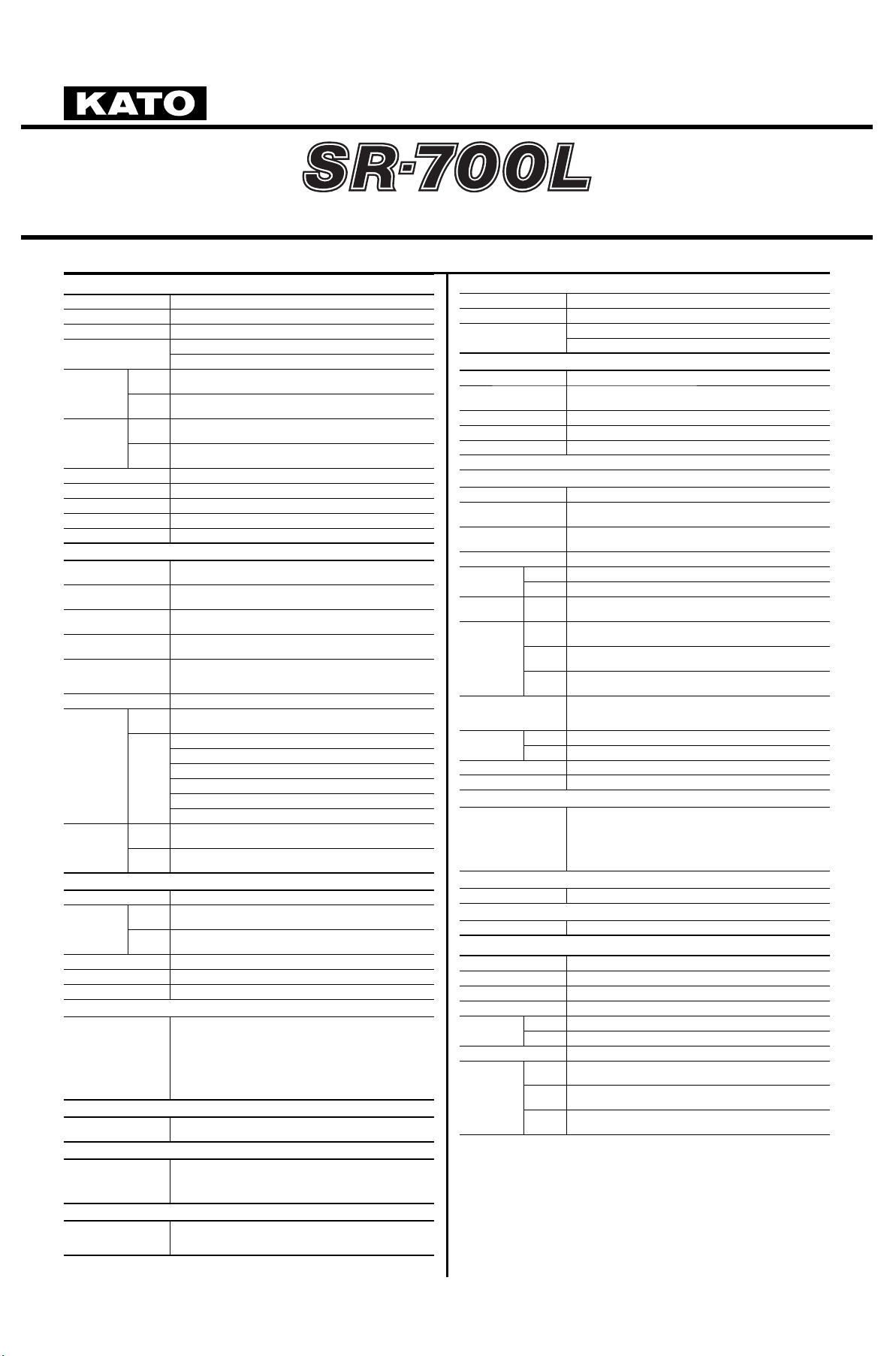
【SPECIFICATION】
■CRANE Specifi cation
Maximum lifting capacity 70ton×2.5m
Boom length 10.0m ― 44.5 m (6 section
)
Fly jib length 8.3m-13.2m (2 section, offset 7° ― 60°
)
Maximum rated lifting
height
45.5m (Boom
)
58.6m (jib
)
Hoisting
line speed
(
winch up
)
Main
winch
160m / min . (at 5th layer
)
Auxil iar y
winch
150m / min . (at 4th layer
)
Hoisting hook
speed
(
winch up
)
Main
winch
(
Par ts of line; 16) : 10m / m in. (at 5th layer
)
Auxil iar y
winch
(
Par ts of line; 1) : 150 m / mi n. (at 4th layer
)
Boom derricking angle 0° ― 84°
Boom derricking time 66sec / (0° ― 84°
)
Boom extending speed 135sec (10.0m ― 44.5m
)
Slewing speed 1.8min
-1
Tail slewing radius 3,550mm
●Equipment and structure
Boom type
Box-shaped, 6-section hydraulically terescopic type
(
Boom section 2 / 3, 4 / 5 / 6 simultaneously operated
)
Jib type
2 sections (2nd section of hydraulically terescopic type
)
(
offset angles 7° ― 60°
)
Boom extension/
retraction equipment
Three hydrauric cylinders and wire ropes used together
Boom derrickin g/lowering
equipment
Two hydraulic cylinders of direct acting type with pressurecompensated fl ow con trol valve
Winch system
Main & Auxiliary winches
Driven by axial plunger type hoisting motor through planetary gear
reduction. Controlled independently by respective operating lever.
Equipped with automatic brake.
Slewing equipment Ball bearing type
Outriggers
Ty pe
Hydraulic H-beam type
(
with fl oat and vertical cylinder in single unit
)
Extension
width
7,600mm (Fully extended
)
7,200mm (Intermedi ately extended
)
6,500mm (Intermedi ately extended
)
5,400mm (Intermedi ately extended
)
4,300 mm (Intermedi ately extended
)
2,690mm (Fully retracted
)
Wire rope for
hoisting
Main
winch
Diameter: 18mm×Length: 240m
Auxil iar y
winch
Diameter: 18mm×Length: 125m
●Hydraulic equipment
Oil pump 4 pumps, plunger type
Hydraulic
motor
Hoisting
motor
Axial plunger type
Slewing
motor
Axial plunger type
Contro l valve Double acting with inte gral c heck an d rel ief va lves
Cylinder Double acting type
Oil reservoir capacity 740L
●Safety devices
ACS (Automatic Crane Stopper with Voice alarm),
Slewing automatic stop system, Boom raise / lower dampening function,
Boom extension / retraction da mpening function, Ou trigger status detector,
Boom derricking / telescoping holding valve, Overhoist prevention device,
Drum lock device (on aux. winch), Winch holding valve, Automatic winch brake,
Winch drum roller, Hydraulic safety valves, Outrigger lock pins,
Slewing lock, Joysti ck control safety s top syste m,
Hydraulic oil temperature warning device, Hydraulic oil return fi lter warning device
●Standard equipment
Hydraulic oil cooler,Working light (on boom, table and cab),
Winch dr um tur ning i ndicati on device, Hook for 34 ton, Hook for 5ton
●Operator's cab
All steel welded construction, 1 person, Rubber mounted,
Adjustable steering wheel, Adjustable seat, Seat belt,
Front windscreen wiper & washer (2 speed wiper),
Roof window wiper & washer, Cigarette lighter, Ashtray, Floor mat
●Optional equipment
Winch view camera, Hook for 70 / 48 ton, Slewing warning buzzer,
Winch over unwinding device, Cab heater, Cab cooler, Fan,
AM/FM Radio, Fire extinguisher, ACS outside indicator
■CARRIER Specifi cation
Maximum traveling speed 49km/h
Gradeability (tan θ
)
60% (computed at G.V.W. = 39,750kg
)
Minimum turning radius
(
center of extreme outer tire
)
11.2m (2 wheel steer)
6.44m (4 wheel steer)
●Engine
Model Mitsubishi 6D24-TLE2A
Ty pe
4 cycle, 6 cylinders, water cooled, direct injection turbo-charged
diesel engine wi th intercooling
Piston displacement 11.945L
Max. power 257kW at 2,200min
-1
Max. torque 1,275N・m at 1,500min
-1
Fuel due to KATO's recommendation only
●Equipment and structure
Drive system 4×4
Torque converter
Engine mounted 3 elements
1 stage (with lock up clutch
)
Tra n s m i ss i o n
Remote mounted full automatic 6 forward & 2 reverse speed wi th
transfer differencial
Number of speeds 6 forward & 2 reverse speed
Axles
Front Planetary, drive/steer type
Rear Planetary, drive/steer type
Suspension
Fron t &
Rear
Hydro-pneumatic suspension
Hydraulic locking device with suspension cylinder
Brake system
Service
brake
Air-over hydraulic disk brake on 4 wheels
(
front and rear in dependent circuit
)
Park ing
brake
Spring applied, electr ically air released parking brake mounted on
front axle, internal expandin g type
Auxil iar y
brake
Exhaust brake, Hydraulic retarder
Steering
Full hydraulic power steering
Completely independent front and rear steering
(
with automatic rear wheel steer ing lock system
)
Tire size
Front 505 / 95 R25 183E ROAD
Rear 505 / 95 R25 183E ROAD
Fuel tank capacity 300 L
Batteries
(
12V-150AH)×2
●Safety devices
Emergency steering device,
Rear wheel steerin g lock system (automatic),
Mis-shifting prevention system, Brake fl uid leak warning device,
Service brake lock, Suspension lock, Engine overspeed alarm,
Radiator coolant level warning device,
Air fi lter service warning device
●Standard equipment
Centralized lubricating system, Bypass oil fi lter
●Optional equipments
Yellow rev. light, Rear view camera, Side view camera
■GENERAL Dimensions
Overall length 12,590mm
Overall width 2,990mm
Overall height 3,680mm
Wheel base 5,300mm
Tre a d s
Fron t 2 ,410m m
Rear 2,410mm
Passenger capacity One person
Gross vehicle
mass
Gross
weight
approx. 39,750kg
Fron t
weight
approx. 19,850kg
Rear
weight
approx. 19,900kg
● Stow the hooks in place before traveling.
● Before you use this machine, read the precautions in the instruction manual thoroughly to
operate it correctly.
● KATO products and specifi cations are subject to i mprovements and changes without notice.
62133000
ROUGH TERRAIN CRANE
Page 3
2
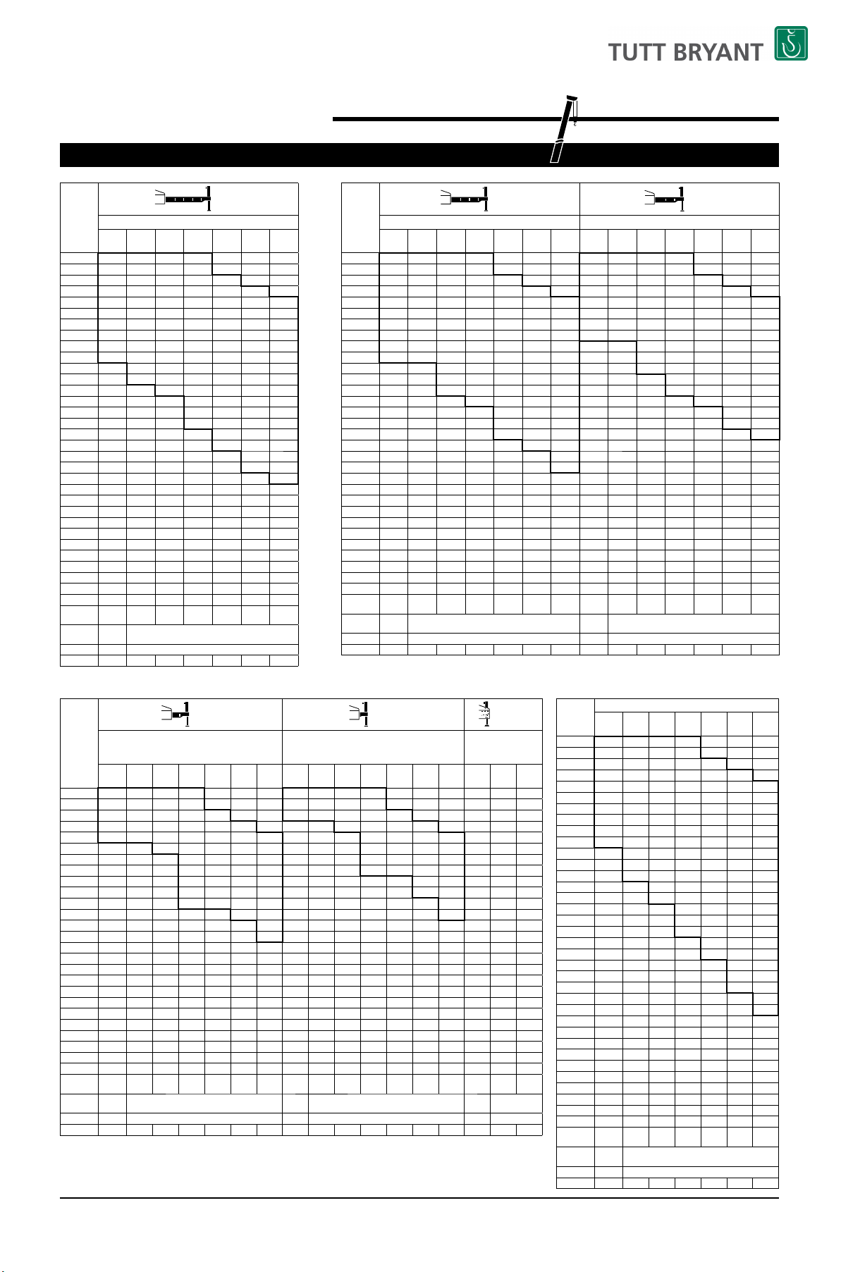
■RATED LIFTING CAPACITY
(
Unit : Metric ton
)
Working
radius (m
)
(7.6m)
Outriggers fully extended (7.6m) (over side and over rear
)
10.0m
Boom
16.9m
Boom
23.8m
Boom
30.7m
Boom
37.6m
Boom
41.5 m
Boom
44.5m
Boom
2.5 70.00* 32.00 23.00 12.50
3.0 61.00* 32.00 23.00 12.50
3.5 55.00* 32.00 23.00 12.50 12.00
4.0 49.20* 32.00 23.00 12.50 12.00 10.00
4.5 44.10 32.00 23.00 12.50 12.00 10.00 8.00
5.0 39.50 32.00 23.00 12.50 12.00 10.00 8.00
5.5 35.70 32.00 23.00 12.50 12.00 10.00 8.00
6.0 32.50 30.50 22.00 12.50 12.00 10.00 8.00
6.5 29.50 28.50 20.60 12.50 12.00 10.00 8.00
7.0 26.80 26.00 19.30 12.50 12.00 10.00 8.00
7.5 24.00 18.20 12.50 12.00 10.00 8.00
8.0 22.00 17.20 12.50 12.00 10.00 8.00
9.0 17.50 15.40 12.50 12.00 10.00 8.00
10.0 14.00 13.80 12.50 10.90 10.00 8.00
11.0 11. 40 11.2 0 11.3 0 10.0 0 9 .20 8.00
12.0 9.40 9.20 10.30 9.20 8.40 8.00
13.0 7.90 7.65 8.70 8.40 7.80 7.30
14.0 6.40 7.40 7.80 7.20 6.80
15.0 5.35 6.35 7.00 6.60 6.30
16.0 4.50 5.45 6.10 6.20 5.80
17.0 3.80 4.75 5.30 5.55 5.40
18.0 3 .15 4.10 4.65 4.9 0 5. 00
19.0 2.60 3.55 4.10 4. 35 4.50
20.0 2.15 3.05 3.60 3.85 4.00
21.0 2.60 3.15 3.40 3.55
22.0 2.25 2.75 3.00 3.15
24.0 1.60 2.10 2.30 2.45
26.0 1.05 1.55 1.7 5 1. 90
28.0 1.10 1.30 1.45
30.0 0.75 0.95 1.05
32.0 0.60 0.70
33.0 0.55
Critical
boom angle
────
28° 33° 37°
Standard
hook
for 70*/48 ton
for 34 ton
Hook mass
530*/470kg
330kg
Par ts of l in e
16*/10754444
10.0m ― 44.5m Boom
(
Unit : Metric ton
)
Working
radius (m
)
(7.2m) (6.5m)
Outriggers inter mediately extended (7.2m) (over side)Outriggers inter mediately extended (6.5m) (over side
)
10.0m
Boom
16.9m
Boom
23.8m
Boom
30.7m
Boom
37.6m
Boom
41.5 m
Boom
44.5m
Boom
10.0m
Boom
16.9m
Boom
23.8m
Boom
30.7m
Boom
37.6m
Boom
41.5 m
Boom
44.5m
Boom
2.5 48.00 32.00 23.00 12.50 48.00 32.00 23.00 12.50
3.0 48.00 32.00 23.00 12.50 48.00 32.00 23.00 12.50
3.5 48.00 32.00 23.00 12.50 12.00 46.00 32.00 23.00 12.50 12.00
4.0 46.00 32.00 23.00 12.50 12.00 10.00 42.00 32.00 23.00 12.50 12.00 10.00
4.5 42.00 32.00 23.00 12.50 12.00 10.00 8.00 38.00 32.00 23.00 12.50 12.00 10.00 8.00
5.0 38.50 32.00 23.00 12.50 12.00 10.00 8.00 34.50 32.00 23.00 12.50 12.00 10.00 8.00
5.5 35.00 32.00 23.00 12.50 12.00 10.00 8.00 31.50 32.00 23.00 12.50 12.00 10.00 8.00
6.0 32.00 30.50 22.00 12.50 12.00 10.00 8.00 29.00 30.50 22.00 12.50 12.00 10.00 8.00
6.5 29.50 28.50 20.60 12.50 12.00 10.00 8.00 25.00 25.80 20.60 12.50 12.00 10.00 8.00
7.0 26.80 26.00 19.30 12.50 12.00 10.00 8.00 21.50 21.80 19.30 12.50 12.00 10.00 8.00
7.5 23.10 18.20 12.50 12.00 10.00 8.00 18.80 18.20 12.50 12.00 10.00 8.00
8.0 20.50 17.20 12.50 12.00 10.00 8.00 16.40 16.20 12.50 12.00 10.00 8.00
9.0 16.00 15.40 12.50 12.00 10.00 8.00 12.90 12.70 12.50 12.00 10.00 8.00
10.0 12.70 12.40 12.50 10.90 10.00 8.00 10.30 10.00 11.25 10.90 10.00 8.00
11.0 10.30 10.10 11.10 10.00 9.20 8.00 8.40 8.10 9.30 9.80 9.20 8.00
12.0 8.50 8.25 9.25 9.20 8.40 8.00 6.85 6.60 7.70 8.40 8.40 8.00
13.0 7.10 6.85 7.80 8.40 7.80 7.30 5.65 5.40 6.45 7.10 7.20 7.30
14.0 5.70 6.65 7.25 7.20 6.80 4.45 5.45 6.05 6.35 6.50
15.0 4.75 5.65 6.30 6.55 6.30 3.60 4.60 5.20 5.45 5.60
16.0 3 .95 4.85 5 .45 5.70 5.80 2.90 3.90 4.5 0 4. 75 4.90
17.0 3.30 4.15 4.75 5.00 5.15 2.35 3.30 3.85 4.10 4.25
18.0 2.70 3.55 4.15 4.40 4.55 1.85 2.75 3.35 3.55 3.70
19.0 2.20 3.05 3.60 3.85 4.00 1.40 2.30 2.85 3.10 3.25
20.0 1.75 2.60 3.15 3.40 3.50 1.00 1.90 2.45 2.70 2.80
21.0 2.20 2.75 2.95 3.10 1.55 2.10 2.30 2.45
22.0 1.85 2.40 2.60 2.75 1.25 1.75 2.00 2.10
24.0 1.2 5 1. 75 1.95 2. 10 0.70 1. 20 1.45 1.55
26.0 0.75 1.25 1.45 1.60 0.75 0.9 5 1.10
28.0 0.85 1.05 1.15 0.60 0.70
30.0 0.65 0.80
31.0 0.65
Critical
boom angle
────
35° 38° 41°
───
25° 40° 43° 47°
Standard
hook
for 48 ton
for 34 ton
for 48 ton
for 34 ton
Hook mass
470kg 3 30kg 47 0kg 33 0kg
Par ts of l in e
1075444410754444
(
Unit : Metric ton
)
Working
radius (m
)
(5.4m) (4.3m) (2.69m)
Outriggers inter mediately extended (5.4m) (over side)Outriggers inter mediately extended (4.3m) (over side
)
Outriggers completely retracted
(
blocked on vartical cylinders
)
(
over side
)
10.0m
Boom
16.9m
Boom
23.8m
Boom
30.7m
Boom
37.6m
Boom
41.5 m
Boom
44.5m
Boom
10.0m
Boom
16.9m
Boom
23.8m
Boom
30.7m
Boom
37.6m
Boom
41.5 m
Boom
44.5m
Boom
10.0m
Boom
16.9m
Boom
23.8m
Boom
2.5 48.00 32.00 23.00 12.50 38.00 30.00 23.00 12.50 20.00 15.00 12.00
3.0 48.00 32.00 23.00 12.50 38.00 30.00 23.00 12.50 20.00 15.00 12.00
3.5 46.00 32.00 23.00 12.50 12.00 38.00 30.00 23.00 12.50 12.00 18.00 15.00 12.00
4.0 42.00 32.00 23.00 12.50 12.00 10.00 31.00 29.60 23.00 12.50 12.00 10.00 14.00 13.70 12.00
4.5 38.00 32.00 23.00 12.50 12.00 10.00 8.00 24.00 24.30 20.80 12.50 12.00 10.00 8.00 11.30 11.00 9.90
5.0 32.20 30.60 23.00 12.50 12.00 10.00 8.00 20.00 19.40 17.60 12.50 12.00 10.00 8.00 9.30 9.00 8.30
5.5 25.90 25.20 22.40 12.50 12.00 10.00 8.00 16.50 16.00 15.10 12.50 12.00 10.00 8.00 7.80 7.40 7.00
6.0 21.50 20.90 19.30 12.50 12.00 10.00 8.00 13.90 13.40 13.00 12.50 12.00 10.00 8.00 6.60 6.50 5.90
6.5 18.20 17.60 16.90 12.50 12.00 10.00 8.00 11.90 11.40 11.30 11.60 11.50 10.00 8.00 5.60 5.20 5.00
7.0 15.70 15.10 14.80 12.50 12.00 10.00 8.00 10.40 9.80 9.70 10.40 10.35 10.00 8.00 4.80 4.40 4.20
7.5 13.10 12.90 12.50 12.00 10.00 8.00 8.60 8.40 9.30 9.30 9.20 8.00 3.70 3.50
8.0 11.50 11.30 12.10 11.90 10.00 8.00 7.50 7.30 8.30 8.40 8.40 8.00 3.20 2.90
9.0 9.00 8.80 9.95 10.00 9.90 8.00 5.80 5.60 6.60 6.95 7.00 7.00 2.15
10.0 7.20 7.00 8.05 8.45 8.45 8.00 4.60 4.40 5.30 5.80 5.85 5.90 1.25
11.0 5.80 5.55 6.65 7.15 7.25 7.25 3.50 3.30 4.30 4.80 4.90 4.95
12.0 4. 60 4.40 5. 45 6.0 5 6.20 6.25 2.65 2.45 3.45 4.00 4.15 4.20
13.0 3.70 3.50 4.50 5.10 5.35 5.40 1.95 1.70 2.70 3.30 3.50 3.55
14.0 2.70 3.70 4.30 4.55 4.70 1.00 2.10 2.70 2.90 3.00
15.0 2.10 3.05 3.60 3.85 4.00 1.55 2.15 2.40 2.50
16.0 1. 55 2.5 0 3.0 5 3.30 3.45 1.10 1.70 1. 95 2.10
17.0 1.10 2.00 2.55 2.80 2.90 1.30 1.55 1.70
18.0 0.70 1.60 2.10 2.35 2.50
19.0 1. 20 1.7 5 1.9 5 2.10
20.0 0 .90 1.40 1.6 0 1.7 5
21.0 0. 60 1.10 1.30 1.45
22.0 0.85 1.05 1. 20
Critical
boom angle
──
30° 40° 50° 54° 57°
──
46° 53° 60° 63° 65°
─
40° 64°
Standard
hook
for 48 ton
for 34 ton
for 48 ton
for 34 ton
for 48 ton
for 34 ton
Hook mass
470kg 3 30kg
470kg
330kg
470kg
330kg
Par ts of l in e
10754444107544441075
(
Unit : Metric ton
)
Worki ng
radius (m
)
Outriggers extended (over front
)
10.0m
Boom
16.9m
Boom
23.8m
Boom
30.7m
Boom
37.6m
Boom
41.5 m
Boom
44.5m
Boom
2.5 70.00* 32.00 23.00 12.50
3.0 61.00* 32.00 23.00 12.50
3.5 55.00* 32.00 23.00 12.50 12.00
4.0 49.20* 32.00 23.00 12.50 12.00 10.00
4.5 44.10 32.00 23.00 12.50 12.00 10.00 8.00
5.0 39.50 32.00 23.00 12.50 12.00 10.00 8.00
5.5 35.70 32.00 23.00 12.50 12.00 10.00 8.00
6.0 32.50 30.50 22.00 12.50 12.00 10.00 8.00
6.5 29.50 28.50 20.60 12.50 12.00 10.00 8.00
7.0 26.80 26.00 19.30 12.50 12.00 10.00 8.00
7.5 24.00 18.20 12.50 12.00 10.00 8.00
8.0 22.00 17.20 12.50 12.00 10.00 8.00
9.0 19.00 15.40 12.50 12.00 10.00 8.00
10.0 16.00 13.90 12.50 10.90 10.00 8.00
11.0 13.20 12.20 11.30 10.00 9.20 8.00
12.0 11.00 10.70 10.30 9.20 8.40 8.00
13.0 9.30 9.00 9.30 8.40 7.80 7.30
14.0 7.60 8.50 7.80 7.20 6.80
15.0 6.45 7.45 7. 30 6.6 0 6.30
16.0 5.50 6.50 6.80 6.20 5.80
17.0 4.70 5.65 6.25 5.80 5.40
18.0 4.00 4.95 5.50 5.40 5.10
19.0 3.40 4.3 0 4.90 5.10 4.80
20.0 2.85 3 .80 4.35 4. 55 4. 50
21.0 3.30 3.85 4.10 4.20
22.0 2.90 3.40 3.65 3.80
24.0 2.15 2.70 2.90 3.05
26.0 1.60 2.10 2.30 2.40
28.0 1.60 1.80 1. 90
30.0 1.20 1.35 1. 50
32.0 0.85 1.00 1.10
33.0 0.85 0.95
34.0 0.70 0.80
35.0 0.55 0.70
36.0 0.55
Critical
boom angle
─────
23° 29°
Standard
hook
for 70*/48 ton
for 34 ton
Hook mass
530*/470kg
330kg
Par ts of l in e
16*/10754444
Page 4

3
44.5m Boom+8.3m SLJib
44.5m Boom+13.2m SLJib
(6.5m)
Outrigger s inter mediately extende d (6.5m) (over side
)
Boom
angle
(°)
Offset 7°
Offset 25°Offset 45°Offset 60
°
Worki ng
radius (m
)
Load
(
ton
)
Worki ng
radius (m
)
Load
(
ton
)
Worki ng
radius (m
)
Load
(
ton
)
Worki ng
radius (m
)
Load
(
ton
)
84
5.8 4.00 8.6 3.00 10.4 1.90 11.2 1.00
80
10.3 4.00 12.8 3.00 14.4 1.90 14.7 1.00
77
13.4 4.00 15.8 3.00 17.0 1.85 17.3 1.00
75
15.5 4.00 17.5 3.00 18.7 1.80 19.0 1.00
73
17.3 3.70 19.3 2.75 20.3 1.75 20.7 1.00
70
19.7 2.90 21.8 2.45 22.8 1.65 23.1 1.00
68
21.2 2.35 23.3 2.00 24.5 1.60 24.6 1.00
65
23.5 1.60 25.5 1.40 26.7 1.30 26.8 1.00
63
25.0 1.20 27.0 1.00 28.1 0.95 28.2 1.00
60
27.2 0.65 29.1 0.60 30.1 0.55
Critical
boom angle
59° 59° 59° 62°
Standard hook
for 5 to n (Hook mass : 120kg
)
Par ts o f line
1
(7.2m)
Outrigger s inter mediately extende d (7.2m) (over side
)
Boom
angle
(°)
Offset 7°
Offset 25°Offset 45°Offset 60
°
Worki ng
radius (m
)
Load
(
ton
)
Worki ng
radius (m
)
Load
(
ton
)
Worki ng
radius (m
)
Load
(
ton
)
Worki ng
radius (m
)
Load
(
ton
)
84
5.8 4.00 8.6 3.00 10.4 1.90 11.2 1.00
80
10.3 4.00 12.8 3.00 14.4 1.90 14.7 1.00
77
13.4 4.00 15.8 3.00 17.0 1.85 17.3 1.00
75
15.5 4.00 17.5 3.00 18.7 1.80 19.0 1.00
73
17.3 3.70 19.3 2.75 20.3 1.75 20.7 1.00
70
19.9 3.20 21.8 2.45 22.8 1.65 23.1 1.00
68
21.7 2.80 23.5 2.25 24.5 1.60 24.6 1.00
65
23.8 2.10 25.7 1.85 26.8 1.55 26.8 1.00
63
25.3 1.65 27.1 1.45 28.2 1.40 28.2 1.00
60
27.5 1.10 29.3 1.0 0 30.2 0.95
57
29.6 0.70 31.3 0.60 32.2 0.55
Critical
boom angle
56° 56° 56° 62°
Standard hook
for 5 to n (Hook mass : 120kg
)
Par ts o f line
1
(5.4m)
Outrigger s inter mediately extende d (5.4m) (over side
)
Boom
angle
(°)
Offset 7°
Offset 25°Offset 45°Offset 60
°
Worki ng
radius (m
)
Load
(
ton
)
Worki ng
radius (m
)
Load
(
ton
)
Worki ng
radius (m
)
Load
(
ton
)
Worki ng
radius (m
)
Load
(
ton
)
84
5.8 4.00 8.6 3.00 10.4 1.90 11.2 1.00
80
10.3 4.00 12.8 3.00 14.4 1.90 14.7 1.00
77
13.4 4.00 15.8 3.00 17.0 1.85 17.3 1.00
75
15.1 3.60 17.5 3.00 18.7 1.80 19.0 1.00
73
16.7 3.00 19.0 2.55 20.3 1.75 20.7 1.00
70
19.1 2.10 21.4 1.65 22.7 1.55 23.1 1.00
68
20.7 1.50 23.0 1.20 24.3 1.10 24.6 1.00
Critical
boom angle
67° 67° 67° 67°
Standard hook
for 5 to n (Hook mass : 120kg
)
Par ts o f line
1
Boom
angle
(°)
Outriggers extended (over front)
Offset 7°
Offset 25°Offset 45°Offset 60
°
Worki ng
radius (m
)
Load
(
ton
)
Worki ng
radius (m
)
Load
(
ton
)
Worki ng
radius (m
)
Load
(
ton
)
Worki ng
radius (m
)
Load
(
ton
)
84
5.8 4.00 8.6 3.00 10.4 1.90 11.2 1.00
80
10.3 4.00 12.8 3.00 14.4 1.90 14.7 1.00
77
13.4 4.00 15.8 3.00 17.0 1.85 17.3 1.00
75
15.5 4.00 17.5 3.00 18.7 1.80 19.0 1.00
73
17.3 3.70 19.3 2.75 20.3 1.75 20.7 1.00
70
19.9 3.20 21.8 2.45 22.8 1.65 23 .1 1.00
68
21.7 2.90 23.5 2.25 24.5 1.60 24.6 1.00
65
24.1 2.45 25.8 2.05 26.8 1.55 26.8 1.00
63
25.7 2.25 27.4 1.90 28.3 1.50 28.2 1.00
60
27.9 1.75 29.6 1.6 0 30.3 1.45
57
30.0 1.30 31.7 1.15 32.3 1.15
54
32.0 0.90 33.6 0.80 34.0 0.80
49
35.2 0.40 36.5 0.35 37.0 0.35
Critical
boom angle
48° 48° 48° 62°
Standard hook
for 5 to n (Hook mass : 120kg
)
Par ts o f line
1
(4.3m)
Outrigger s inter mediately extende d (4.3m) (over side
)
Boom
angle
(°)
Offset 7°
Offset 25°Offset 45°Offset 60
°
Worki ng
radius (m
)
Load
(
ton
)
Worki ng
radius (m
)
Load
(
ton
)
Worki ng
radius (m
)
Load
(
ton
)
Worki ng
radius (m
)
Load
(
ton
)
84
5.8 4.00 8.6 3.00 10.4 1.90 11.2 1.00
80
10.3 4.00 12.8 3.00 14.4 1.90 14.7 1.00
77
13.0 3.40 15.8 2.55 17.0 1.85 17.3 1.00
75
14.8 2.45 17.2 2.00 18.7 1.70 19.0 1.00
73
16.5 1.75 18.8 1.40 20.3 1.3 0 20.7 1.00
Critical
boom angle
72° 72° 72° 72°
Standard hook
for 5 to n (Hook mass : 120kg
)
Par ts o f line
1
(7.6m)
Outriggers fully extended (7.6m) (over side and over rear
)
Boom
angle
(°)
Offset 7°
Offset 25°Offset 45°Offset 60
°
Worki ng
radius (m
)
Load
(
ton
)
Worki ng
radius (m
)
Load
(
ton
)
Worki ng
radius (m
)
Load
(
ton
)
Worki ng
radius (m
)
Load
(
ton
)
84
7.2 2.50 11.0 1.50 14.3 1.00 15.7 0.60
80
11.8 2.50 15.5 1.50 18.2 1.00 19.5 0.60
77
15.3 2.50 18.6 1.50 21.0 1.00 22.2 0.60
75
17.5 2.50 20.6 1.50 22.9 1.00 23.8 0.60
73
19.6 2.50 22.5 1.45 24.8 1.00 25.4 0.60
70
22.5 2.20 25.2 1. 40 27.3 1.00 27.8 0.6 0
68
24.5 2.05 27.0 1.35 29.0 1.00 29.4 0.60
65
27.2 1.85 29. 6 1.30 31. 4 1.00 31.5 0.60
63
28.9 1.50 31.2 1.25 32.9 0.95 32.9 0.60
60
31.2 1.05 33.6 0.95 35.3 0.90
58
32.5 0.85 35.2 0.70 36.5 0.70
55
34.5 0.55 37.2 0.40 38.3 0.40
Critical
boom angle
54° 54° 54° 62°
Standard hook
for 5 to n (Hook mass : 120kg
)
Par ts o f line
1
(7.6m)
Outriggers fully extended (7.6m) (over side and over rear
)
Boom
angle
(°)
Offset 7°
Offset 25°Offset 45°Offset 60
°
Worki ng
radius (m
)
Load
(
ton
)
Worki ng
radius (m
)
Load
(
ton
)
Worki ng
radius (m
)
Load
(
ton
)
Worki ng
radius (m
)
Load
(
ton
)
84
5.8 4.00 8.6 3.00 10.4 1.90 11.2 1.00
80
10.3 4.00 12.8 3.00 14.4 1.90 14.7 1.00
77
13.4 4.00 15.8 3.00 17.0 1.85 17.3 1.00
75
15.5 4.00 17.5 3.00 18.7 1.80 19.0 1.00
73
17.3 3.70 19.3 2.75 20.3 1.75 20.7 1.00
70
19.9 3.20 21.8 2.45 22.8 1.65 23.1 1.00
68
21.7 2.90 23.5 2.25 24.5 1.60 24.6 1.00
65
24.1 2.30 25.8 2.05 26.8 1.55 26.8 1.00
63
25.7 1.80 27.3 1.70 28.3 1.50 28.2 1.00
60
27.7 1.35 29 .4 1.20 30.3 1.15
57
29.8 0.90 31.4 0.80 32.3 0.75
54
31.8 0.55 33.4 0.45 34.0 0.45
Critical
boom angle
53° 53° 53° 62°
Standard hook
for 5 to n (Hook mass : 120kg
)
Par ts o f line
1
(7.2m)
Outrigger s inter mediately extende d (7.2m) (over side
)
Boom
angle
(°)
Offset 7°
Offset 25°Offset 45°Offset 60
°
Worki ng
radius (m
)
Load
(
ton
)
Worki ng
radius (m
)
Load
(
ton
)
Worki ng
radius (m
)
Load
(
ton
)
Worki ng
radius (m
)
Load
(
ton
)
84
7.2 2.50 11.0 1.50 14.3 1.00 15.7 0.60
80
11.8 2.50 15.5 1.50 18.2 1.00 19.5 0.60
77
15.3 2.50 18.6 1.50 21.0 1.00 22.2 0.60
75
17.5 2.50 20.6 1.50 22.9 1.00 23.8 0.60
73
19.6 2.50 22.5 1.45 24.8 1.00 25.4 0.60
70
22.5 2.20 25.2 1. 40 27.3 1.00 27.8 0.6 0
68
24.5 2.05 27.0 1.35 29.0 1.00 29.4 0.60
65
27.1 1.65 29.6 1.30 3 1.4 1.00 31.5 0.60
63
28.7 1.30 31.1 1.20 32.9 0.95 32.9 0.60
60
31.0 0.85 33.4 0.80 34.9 0.75
58
32.3 0.65 34.9 0.55 36.2 0.45
Critical
boom angle
57° 57° 57° 62°
Standard hook
for 5 to n (Hook mass : 120kg
)
Par ts o f line
1
(6.5m)
Outrigger s inter mediately extende d (6.5m) (over side
)
Boom
angle
(°)
Offset 7°
Offset 25°Offset 45°Offset 60
°
Worki ng
radius (m
)
Load
(
ton
)
Worki ng
radius (m
)
Load
(
ton
)
Worki ng
radius (m
)
Load
(
ton
)
Worki ng
radius (m
)
Load
(
ton
)
84
7.2 2.50 11.0 1.50 14.3 1.00 15.7 0.60
80
11.8 2.50 15.5 1.50 18.2 1.00 19.5 0.60
77
15.3 2.50 18.6 1.50 21.0 1.00 22.2 0.60
75
17.5 2.50 20.6 1.50 22.9 1.00 23.8 0.60
73
19.6 2.50 22.5 1.45 24.8 1.00 25.4 0.60
70
22.5 2.20 25.2 1.40 27.3 1.00 27.8 0.60
68
24.2 1.80 27.0 1.35 29.0 1.00 29.4 0.60
65
26.6 1.25 29 .4 1.10 31.4 1.00 31.5 0.6 0
63
28.3 0.90 31.0 0.80 32.7 0.70 32.9 0.60
Critical
boom angle
62° 62° 62° 62°
Standard hook
for 5 to n (Hook mass : 120kg
)
Par ts o f line
1
(5.4m)
Outrigger s inter mediately extende d (5.4m) (over side
)
Boom
angle
(°)
Offset 7°
Offset 25°Offset 45°Offset 60
°
Worki ng
radius (m
)
Load
(
ton
)
Worki ng
radius (m
)
Load
(
ton
)
Worki ng
radius (m
)
Load
(
ton
)
Worki ng
radius (m
)
Load
(
ton
)
84
7.2 2.50 11.0 1.50 14.3 1.00 15.7 0.60
80
11.8 2.50 15.5 1.50 18.2 1.00 19.5 0.60
77
15.3 2.50 18.6 1.50 21.0 1.00 22.2 0.60
75
17.5 2.50 20.6 1.50 22.9 1.00 23.8 0.60
73
19.5 2.35 22.5 1.45 24.8 1.00 25.4 0.60
70
22.0 1.60 25.0 1.30 27.3 1.00 27.8 0.60
68
23.5 1.20 26.8 0.90 28.9 0.85 29.4 0.60
Critical
boom angle
67° 67° 67° 67°
Standard hook
for 5 to n (Hook mass : 120kg
)
Par ts o f line
1
(4.3m)
Outrigger s inter mediately extende d (4.3m) (over side
)
Boom
angle
(°)
Offset 7°
Offset 25°Offset 45°Offset 60
°
Worki ng
radius (m
)
Load
(
ton
)
Worki ng
radius (m
)
Load
(
ton
)
Worki ng
radius (m
)
Load
(
ton
)
Worki ng
radius (m
)
Load
(
ton
)
84
7.2 2.50 11.0 1.50 14.3 1.00 15.7 0.60
80
11.8 2.50 15.5 1.50 18.2 1.00 19.5 0.60
77
15.3 2.50 18.6 1.50 21.0 1.00 22.2 0.60
75
17.0 2.00 20.6 1.50 22.9 1.00 23.8 0.60
73
18.8 1.40 22.3 1.10 24.6 1.00 25.4 0.60
Critical
boom angle
72° 72° 72° 72°
Standard hook
for 5 to n (Hook mass : 120kg
)
Par ts o f line
1
Boom
angle
(°)
Outriggers extended (over front)
Offset 7°
Offset 25°Offset 45°Offset 60
°
Worki ng
radius (m
)
Load
(
ton
)
Worki ng
radius (m
)
Load
(
ton
)
Worki ng
radius (m
)
Load
(
ton
)
Worki ng
radius (m
)
Load
(
ton
)
84
7.2 2.50 11.0 1.50 14.3 1.00 15.7 0.60
80
11.8 2.50 15.5 1.50 18.2 1.00 19.5 0.60
77
15.3 2.50 18.6 1.50 21.0 1.00 22.2 0.60
75
17.5 2.50 20.6 1.50 22.9 1.00 23.8 0.60
73
19.6 2.50 22.5 1.45 24.8 1.00 25.4 0.60
70
22.5 2.20 25.2 1.40 27.3 1.00 27.8 0.60
68
24.5 2.05 27.0 1.35 29.0 1.00 29.4 0.60
65
27.2 1.85 29. 6 1.30 31.4 1.00 31. 5 0.60
63
28.9 1.70 31.2 1.25 32.9 0.95 32.9 0.60
60
31.4 1.45 33.8 1.20 35.3 0.90
58
32.9 1.15 35.3 1.05 36.6 0.90
55
35.0 0.80 37.3 0.75 38.5 0.70
50
37.9 0.45 40.0 0.40 40.8 0. 40
Critical
boom angle
49° 49° 49° 62°
Standard hook
for 5 to n (Hook mass : 120kg
)
Par ts o f line
1
Page 5

4
■When the outriggers are not used
(
Unit : Metric ton
)
Working
radius (m
)
Stationary on rubber Pick & carry (less than 2 km/h
)
Working
radius (m
)
10.0m Boom 16.9m Boom 23.8m Boom 10.0m Boom 16.9m Boom 23.8m Boom
Over
front
360°
full
range
Over
front
360°
full
range
Over
front
360°
full
range
Over
front
360°
full
range
Over
front
360°
full
range
Over
front
360°
full
range
3.5 20.00 12.00 15.00 8.50 9.00 4.50 14.50 8.00 10.50 6.50 7.50 3.30 3.5
4.0 20.00 9.80 15.00 8.50 9.00 4.50 14.50 7.00 10.50 6.50 7.50 3.30 4.0
4.5 17.40 8.00 15.00 7.20 9.00 4.50 12.50 6.00 10.50 5.40 7.50 3.30 4.5
5.0 15.50 6.60 15.00 6.10 9.00 4.50 11.00 5.10 10.50 4.50 7.50 3.30 5.0
5.5 14.00 5.50 13.70 5.10 9.00 4.50 10.00 4.30 10.50 3.75 7.50 3.30 5.5
6.0 12.80 4.65 12.40 4.25 9.00 3.80 9.10 3.60 9.50 3.15 7.50 2.90 6.0
6.5 11.70 3.90 11.30 3.60 8.60 3.20 8.40 3.00 8.60 2.70 7.00 2.50 6.5
7.0 10.70 3.20 10.30 3.00 8.20 2.70 7.80 2.50 7.80 2.25 6.55 2.00 7.0
7.5 9.40 2.50 7.80 7.10 1.85 6.10 7.5
8.0 8.60 1.90 7.40 6.50 1.50 5.70 8.0
8.5 7.70 1.40 7.00 5.85 1.20 5.35 8.5
9.0 7.00 6.60 5.30 0.90 5.00 9.0
10.0 5.70 5.50 4.30 4.10 10.0
11.0 4.75 4.60 3.50 3.35 11.0
12.0 4.00 3.75 2.90 2.65 12.0
13.0 3.35 3.05 2.45 2.00 13.0
14.0 2.50 1.50 14.0
15.0 2.00 1.00 15.0
16.0 1.60 16.0
17.0 1.20 17.0
18.0 0.80 18.0
Critical
boom angle
───
49° 30° 68°
───
49° 41° 68°
Critical
boom angle
Standard
hook
for 34 ton for 34 ton
Standard
hook
Hook mass
330kg 330kg
Hook mass
Par ts of li ne
55
Par ts of li ne
Page 6

5
■Notes for the lifting capacity chart
■When the outriggers are used
1. The lifting capacity charts are based on the jib stowed on the
boom side.
2. The lifting capacity chart indicates the maximum load which can
be lifted by this crane provided it is level and standing on fi rm
level ground. The values in the chart include the mass of the
main hook and slings for boom operation, and auxiliary hook
and slings for jib operation. [70 ton hook (mass: 530kg), 48 ton
hook (mass: 470kg), 34 ton hook (mass: 330kg), 5 ton hook
(
mass: 120kg)
]
Within the chart the fi gures in the area bordered with a thick line
are based on struc tural limitati on s whi le other f igu res are
determined by stability limitations.
3. The working radii are the actual values allowing for boom and jib
defl ection. Therefore you must always operate the crane on the
basis of the working radius.
4. The jib working radius is based on the jib mounted on the end of
the 44.5m boom. When operating at other boom lengths, use
the boom angle alone as the criterion.
5. Do not operate the jib when the outri ggers are completely
retracted.
6. The lifting capacities for the over sides vary with the outrigger
extensi on wid th. Therefore for ea ch outr i gger exten sion
condition you should work according the lifting capacity chart.
Use the front area lifting capacity chart for the front area lifting
capacity, and the lifting capacity chart of outrigger full extension
for the rear area lifting capacity.
Outrigger
extension status
Full extension
(
7.6m
)
Intermedi ate
exten sion
(
7.2 ― 5.4m
)
Intermedi ate
exten sion (4.3m
)
Full retraction
Area α◦ Only front area 40 30 15 3
7. The lifting capacity of the rooster sheave is the lifting capacity of
the boom minus the mass of all attached hook, slings etc. to the
boom, with an upper limit of 5,000kg.
[
The hook for use with the rooster sheave is the 5 ton hook
(
mass: 120kg) with one part of line.
]
8. If the boom length, boom angle jib length, jib angle and/or
working radius exceeds the rated value, use the lifting capacity
for the rated value or for the next one, whichever gives the
smaller lifting capacity.
9. If you are working with the boom while the jib is rigged, subtract
2.6 ton from the each lifting capacity of the boom for the
outrigger extension width 7.6m, 7.2m, 6.5m or 5.4m, and 3.0 ton
for the outrigger extension width 4.3m, with an upper limit of 18
ton.
Do not use the rooster sheave in this situation. And do not
operate the boom while the jib is rigged, when the outriggers are
retracted.
[
The main hook for use with the jib rigged is 34 ton hook (mass:
330kg).
]
10. In whatever working conditions the corresponding boom critical
angel is shown in the chart. The crane can tip over if the boom
is lowered below the critical angle even if unloaded.
Therefore, never lower the boom below these angles.
11. If you work with 16 parts of line on the hook (with * marked in
the lifting capacity chart), use the rooster sheave and sheave
bracket.
12. The standard parts of line for each boom length are as indicated
in the chart. If you work with a non-standard number of parts of
line, do not exceed 45.1kN (4.6tf) per wire rope respectively.
13. Crane operation is permissible up to a wind speed of 10m/s.
Even in relatively light wind conditions, extra care should be
taken when handling loads presenting large wind catching
areas.
14. Kato bears no liability whatsoever for damage, crane tipping or
other accident caused by crane operations which differ from the
directions contained in the instruction manual and the warning
labels.
■When the outriggers are not used
1. The lifting capacity charts are based on the jib stowed on the
boom side.
2. The lifting capacity chart indicates the maximum load the crane
can lift when its body is level on fi r m level ground with all tires
inflated to the rated pressure and the suspensi on cylinder
completely retracted. The values in the chart include the mass
of the main hook and slings.
Within the chart the fi gures in the area bordered with a thick line
are based on struc tural limitati on s whi le other f igu res are
determined by stability limitations.
[
Tire pressure: 800kPa (8.0kgf/cm
2
)]
3. The working radii are the actual values allowi ng for boom
defl ection. Therefore you must always operate the crane on the
basis of the working radius.
4. The lifting capacity differs between the front area capacity and
the full range capacity. When slewing from the front to the side,
take care that the crane could not be over loaded.
Crane operation
Stationary
crane-on-rubber
operation
Pick and carry
operation
Area α◦ 11
5. The lifting capacity of the rooster sheave is the lifting capacity of
the boom minus the mass of the 34 ton hook (330kg), with an
upper limit of 5,000kg.
[
The hook for use with the rooster shave is the 5 ton hook (mass:
120kg) with one part of line.
]
6. Do not work with the jib or with a boom length of more than
23.8m.
7. For stationary crane-on-rubber operation, the parking brake and
service brake lock device must be engaged.
8. For pick and carry operation, the super-slow speed switch must
be switched to “ON” and the shift lever set to speed 1.
9. For pick and carry operation, lower the load to just above the
ground and keep your speed strictly below 2km/h to avoid
swinging the load.
Take particular care to avoid sharp turns, sudden starts and
stops.
10. Never operate the crane during pick and carry operation. The
slewing brake must be applied.
11. If the boom length or working radius exceeds the rated value,
use the lifting capacity for the rated value or for the next one,
whichever gives the smaller lifting capacity.
12. In whatever working conditions the corresponding boom critical
angel is shown in the chart. The crane can tip over if the boom
is lowered below the critical angle even if unloaded.
Therefore, never lower the boom below these angles.
13. The standard parts of line for each boom length are as indicated
in the chart. If you work with a non-standard number of parts of
line, do not exceed 45.1kN (4.6tf) per wire rope respectively.
14. Crane operation is permissible up to a wind speed of 10m/s.
Even in relatively light wind conditions, extra care should be
taken when handling loads presenting large wind catching
areas.
15. Kato bears no liability whatsoever for damage, crane tipping or
other accident caused by crane operations which differ from the
directions contained in the instruction manual and the warning
labels.
Page 7

6
62133000
■WORKING RANGE
Page 8

7
■Overall view
■Minimum path width
Reduced scale: 1/100 Unit (mm
)
●Left turn in two-wheel steering mode ●Left turn in 4-wheel steering mode
・R1=11.20m ・A=5.86m (Width of entrance
)
・R1=6.44m ・A0=5.39m (Width of entrance
)
(
Minimum turning radius)・B=5.86m (Width of wheel exit
)(
Minimum turning radius)・A
1
=3.84m (Width of wheel entrance
)
・R
2
=11.45m ・C=6.75m (Width of chassis exit
)
・R2=6.69m ・B =3.84m (Width of wheel exit
)
(
Tu r ni ng ra d iu s o f ex t re me l y
outer tyre
)
・D=8.11m (Width of exit at end of boom
)(
Tu r ni n g r a d iu s o f
extremely outer tyre
)
・C =5.39m (Width of chassis exit
)
・D =6.90m (Width of exit at end of boom
)
・R
3
=12.34m ・R3=7.68m
(
Chassis turning radius
)(
Chassis turning radius
)
・R
4
=13.70m ・R4=9.13m
(
Boom end turning radius
)(
Boom end turning radius
)
・R
5
=7.13m ・R5=3.14m
(
Turning radius extremely chassis inner
)(
Turning radius extremely chassis inner
)
Note: The above values are based on calculations.
Page 9

8
■Overall view
Reduced scale: 1/100 Unit (mm
)
9-37, Higashi-ohi 1-chome,Shinagawa-ku, Tokyo, 140-0011, Japan
Tel. : Head Offi ce Tokyo (03) 3458 -1111
Overseas Marketing Department. Tokyo
(03)
3458 -1115
Fax. : Tokyo (03) 3458-1163
URL http://www.kato-works.co.jp
C02651
10.2008-3000 (TI) 1
We acquired the "ISO 9001" certifi cation which is
an international standard for quality assurance.
* KATO products and spe cifi cations are subject to improvements and changes without notice.
Address inguiries to:
Page 10

CONTACT US
Tutt Bryant Heavy Lift & Shift locations
Port Hedland
Karratha
Darwin
Ormeau
Western Region
Perth
Karratha
Port Hedland
Northern Region
Darwin
Eastern Region
Redcliffe
08 9230 0500
08 9143 0089
08 9172 2288
08 8924 1333
Muswellbrook
Singleton
Dandenong
Doveton
per@tuttbryant.com.au
krt@tuttbryant.com.au
porthedland@tuttbryant.com.au
dwn@tuttbryant.com.au
Brisbane (Ormeau)
Melbourne (Dandenong)
Melbourne (Doveton)
Sydney
Hunter Region
Muswellbrook
For more information visit us online @ www.tuttbryant.com.au
07 5540 8700
03 9554 0300
03 9793 7755
02 9646 6000
02 6541 6444
bne@tuttbryant.com.au
mel@tuttbryant.com.au
mel@tuttbryant.com.au
syd@tuttbryant.com.au
mbk@tuttbryant.com.au
 Loading...