Kason 11845000014 Installation Manual

Intelli-Vent™
1845 PRESSURE RELIEF PORT 120V - INSTALLATION INSTRUCTIONS
Part No. 11845000014
Materials Required:
Pressure Relief Port 120V
Silicone Caulk
Utility Box w/ Cover
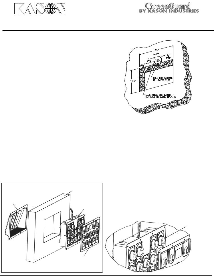
1.Locate position of the pressure relief port on wall and mark large opening as shown in Fig 1. Note: check that there is no electrical conduit inside panel or on either surface that may be damaged by installation. Because the pressure relief port nozzles dispurse a large amount of humid atmosphere the area immediately in front of, and surrounding the nozzle cover, must remain free of obstruction. Do not place shelving, or product in this area.
2.Cut completely through wall as shown for large opening.
3.Locate the small opening for the electrical box, on either the cold or warm side of the wall (small opening dimensions shown are for Kason Utility Box ELO- 58361-1/2). Cut through metal on one side only and cut insulation away as shown in Fig. 1 for electrical box.
Fig. 1
5.Place a bead of caulk all around the frame assemblly mounting flange to provide airtight seal against wall. (Kason SiliconeAdhesive Sealant 63700000001 is recommended)
6.On cold side of wall, position frame assembly as shown in Fig. 2. Insert frame assemblly into wall centering it within opening, guide power wires into electrical box as you do so. Push flange firmly into engagement with wall, seating caulk.
4.Position electrical box in small cutout with wire holes large cutout. Cut hole through insulation from electrical box to large opening. Secure electrical box as needed.
|
|
WALL |
HOOD |
|
FRAME |
|
|
ASSEMBLY |
WARM |
|
|
SIDE |
|
|
|
|
NOZZLE |
Fig. 2 |
COLD |
COVER |
|
||
SIDE |
|
7.Insert round gaskets into individual ventilator body as shown inenlarged view.
8.Place thin line of caulk all around flange of nozzle cover
to seal against frame assembly. Orient nozzle cover so that nozzles align with ventilator openings in frame assembly. Match hole position in nozzle cover to mounting holes in frame assembly. Use self drilling screws or drill for appropriate fasteners and secure nozzle cover to wall.
(continued on reverse side)
ENLARGED |
|
VIEW |
GASKET |
Page 1 |
IS-1845-14 R6 7/11/14 |
|
 Loading...