

User's Manual
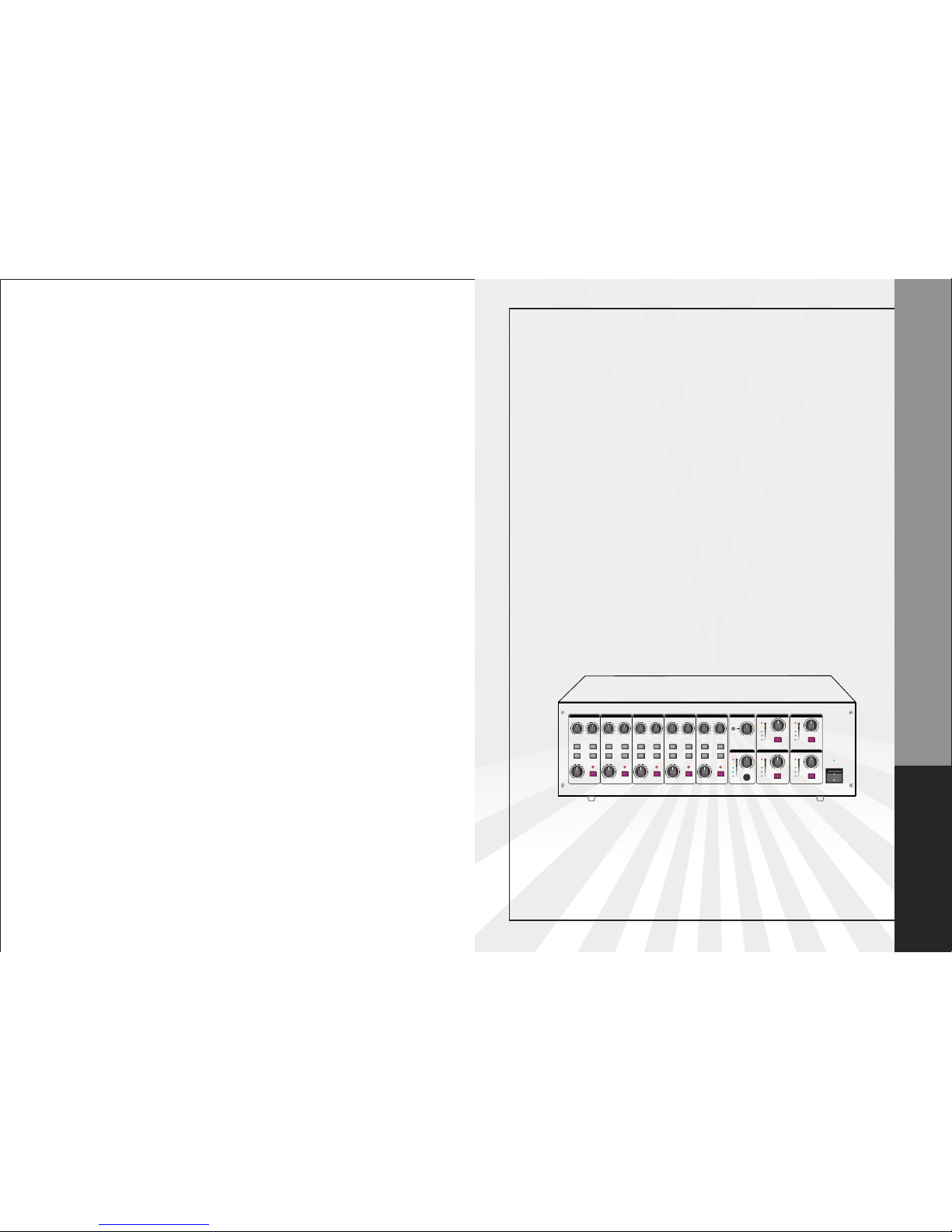
PROFESSIONAL PUBLIC ADDRESS AMPLIFIER
PROFESSIONAL
PUBLIC
ADDRESS
AMPLIFIER
NF00137
0 10 0 10 0 10 0 10 0 10
0 10 0 10 0 10
0 10
0 10 0 10
INPUT 1 IN PUT 2 I NPUT 3 INPUT 4 INPUT 5
AUX
ZONE 1 ZONE 2
ZONE 1 ZONE 2MONITOR
BASS
TREBLE T REBLE
BASS
TREBLE
BASS BASS
TREBLE T REBLE
BASS
LEVEL
-10 +10 -10 +10 - 10 +10 - 10 +10 -10 +10 -10 +10 -10 +10 -10 +1 0 -10 +10 -10 +10
ZONE 1
ZONE 2
ZONE 1
ZONE 2 ZONE 2
ZONE 1
ZONE 2
ZONE 1
ZONE 2
ZONE 1
ZONE 3
ZONE 4
ZONE 3
ZONE 4 ZONE 4
ZONE 3
ZONE 4
ZONE 3
ZONE 4
ZONE 3
LEVEL LEVEL LEVEL LEVEL LEVEL
MUTEMUTEMUTEMUTEMUTE
LEVEL L EVEL LEVEL
MONMON
MONMON
LEVELLEVEL
POWER
1
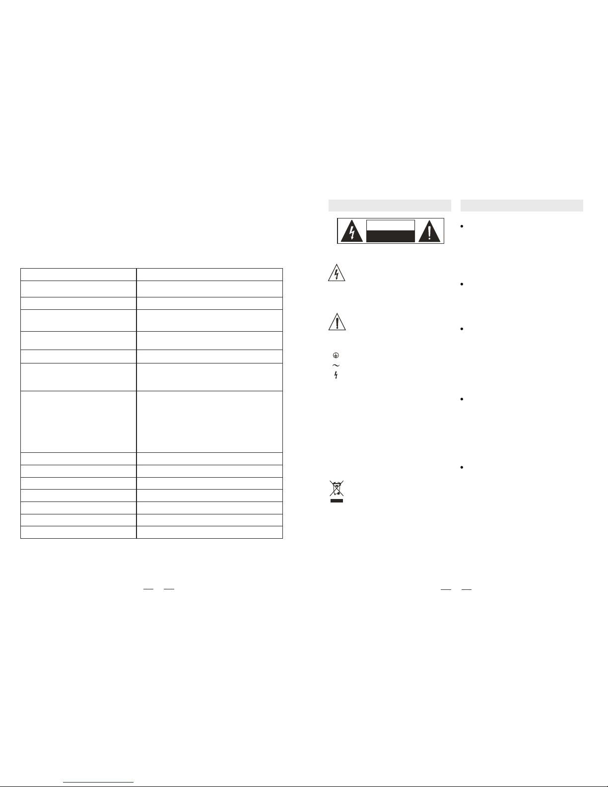
CAUTION
RISK OF ELECTRIC SHOCK
DO NOT OPEN
SAFE TY INST RU CTI ONS
Des cribe s prec autio ns tha t shou ld
be o bserv ed to p reven t dama ge to
the appar atus.
CAUTION:
The symbo l is us ed to i ndica te tha t
som e haza rdous live t ermin als ar e
inv olved with i n this appar atus,
eve n unde r the n ormal opera ting
con ditio ns.
The symbo l is us ed in t he ser vice
doc ument ation to ind icate that
spe cific compo nent s hall b e only
rep laced by the compo nent s pecifi ed in t hat do cumen tatio n for
saf ety re asons .
Pro tecti ve Gro und Term in al
AC m ains ( Alter natin g Curr ent)
Haz ardou s Live Term in al
ON:
OFF:
Den otes t he app aratu s turn s on.
Den otes t he app aratu s turn s off,
bec ause o f usin g the s ingle pole
swi tch, b e sure to unp lug th e AC
pow er to p reven t any e lectr ic sho ck
bef ore yo u proc eed yo u serv ice.
WAR NING:
Des cribe s prec autio ns tha t shou ld
be o bserv ed to p reven t the d anger
of i njury or dea th to t he use r.
Dis posin g of th is pro duct s hould not
be p laced in mun icipa l wast e and
sho uld be separ ate co llect ion.
WAR NING
Ens ure th e sour ce vol tage m atche s the
vol tage o f the p ower s upply befor e turn ing
ON t he app aratu s.
Unp lug th is app aratu s duri ng lig htnin g
sto rms or when u nused for lo ng per iods
of t ime.
Pow er supp ly
The exter nal wi ring c onnec ted to the ou tput hazar dous l ive te rmina ls req uires
ins talla tion b y an in struc ted pe rson, or
the use of ready -made leads or cor ds.
The re are maybe some a re as w ith hi gh
vol tages insid e, to r educe the ri sk of e lect ricsh ock, d o not r emove any co ver if
the power suppl y is co nnect ed,
Do no t Remov e any Cov er
Ext ernal C onnec tion
The cover shoul d be re moved by the qualifi ed per sonne l only.
No u ser se rvice able p arts i nside .
To pre vent a fire, make s ure to use fu ses
wit h spec ified stand ard (c urren t ,vol tage,
typ e). Do not us e a dif fe re nt f us e o r s hor t
cir cuit t he fus e hold er.
Bef ore re placi ng the fuse, turn O FF the
app aratu s and d iscon necte d the p ower
sou rce.
Fus e
Mak e sure to con nect t he pro tecti ve
gro undin g to pr event any el ectri c shoc k
bef ore tu rning ON the appar atus.
Nev er cut off th e i nt ern al or ex ter na l p ro tec tive g round ing wi re or d iscon nect t he
wir ing of prote ctive groun ding t ermin al.
Pro tecti ve Grou nding
8
29. THE MI C/LIN E INPU T CONN ECTOR .
These are the channels from Channel1 to Channel3. You can connect balanced, low impedance
microphones to the XLR socket. On the 1/4" phone jack you can connect either a microphone
or a line level instrument. You shall never connect an unbalanced microphone lt the XLR socket
if you do not want to damage both the Microphone and the Mixer.
TEC HNICA L SPE CIFIC ATIO N
OUT PUT POW ER CAPACI TY
RMS : 60W x 4
AC: 11 0-120 V 50/60 Hz
AC: 2 20-24 0V 50/6 0Hz
FRE QUENC Y RESPO NSE
50H z~18K Hz (±3dB)
MIC : - 50dB
AUX : - 18dB
INP UT SENS ITIVI TY
BAS S: ±10dB ( 100Hz )
TRE BLE: ±10 dB (10K Hz)
<0. 5%
MIC≥6 5dB
AUX ≥7 5dB
MIC L EVEL CON TROL
AUX L EVEL CON TROL
TON E CONTR OL (BASS , TREBL E)
AC SW ITCH
PHO NE CONT ROL
MON ITOR CO NTROL
EAC H CHANN EL HAS THE I NPUT LE VEL CONT ROL
4Ω, 8Ω
50V,7 0V, 100V
YES
YES
YES
YES
420 X342X 133mm
TON E CONTR OLS
OUT PUT IMP ECANC E
LIN E OUTPU T
CHI ME FUNC TION
VU- METER ( LED)
TEL PHONE PA GING LE LECT FUN CTION
INP UT 1 PRIO RITY
DIM ENSIO N
SIGNNAL / NOISE RATIO
TOTAL HARMONIC DISTORTION
POWER SUPPLY
CONTROLS
LIN E : -17dB
TEL . : -30dB
 Loading...