


1
Powered Wheelchair User's Manual
Morgan Series
(Morgan Sling Seat / Morgan Seat / Morgan KISS Seat)

2
release 04-2019

3
1. Index
Index
1. Index ............................................................................................................................................................... 3
2. how to contact Karma. ................................................................................................................................... 8
3. Declaration of conformity .............................................................................................................................. 9
4. Introduction ................................................................................................................................................. 10
5. Preface ......................................................................................................................................................... 12
6. General warning. .......................................................................................................................................... 13
6.1 IMPORTANT ............................................................................................................................................ 13
6.2 Ramps ..................................................................................................................................................... 15
6.3 Electrical ................................................................................................................................................. 15
6.4 Batteries ................................................................................................................................................. 15
6.5 spray test ................................................................................................................................................ 16
6.6 Stairways ................................................................................................................................................ 16
6.7 Escalator ................................................................................................................................................. 17
7. You and your Karma service provider .......................................................................................................... 17
8. Classification & intended use ....................................................................................................................... 17
8.1 CE marking ............................................................................................................................................. 17
9. Safety ............................................................................................................................................................ 19
9.1 Before Driving ........................................................................................................................................ 19
9.2 Traffic Rules ............................................................................................................................................ 19
9.3 Practice Driving ...................................................................................................................................... 19
9.4 No Passengers ........................................................................................................................................ 19
9.5 No Hauling Heavy Goods ....................................................................................................................... 19
9.6 Rain ........................................................................................................................................................ 19
9.8 General Warning .................................................................................................................................... 20
9.9 Railroad Crossing .................................................................................................................................... 20
9.10 Circumstances to Avoid ........................................................................................................................ 20
9.11 Mobile Phones and Other Electric Equipment .................................................................................... 20
9.12 Ramps, Inclines and Drops ................................................................................................................... 21
9.13 Maximum User Weight Limit ............................................................................................................... 22

4
10. The Morgan Series Labeling ....................................................................................................................... 22
11. EMI/RFI ....................................................................................................................................................... 23
11.1 Electromagnetic interference from radio wave sources ...................................................................... 24
11.2 The sources of radiated EMI can be broadly classified into three types: ............................................ 24
11.3 Powered vehicle electromagnetic interference (EMI) ......................................................................... 24
11.4 Warnings .............................................................................................................................................. 25
12. The wheelchair parts.................................................................................................................................. 26
12.1 Morgan with Captain seat .................................................................................................................... 26
12.2 Morgan with Sling seat ........................................................................................................................ 28
12.3 Morgan with KISS Seat ......................................................................................................................... 29
13. Operation. .................................................................................................................................................. 30
13.1 Controller cable tie location. ................................................................................................................ 30
13.2. How to operate your wheelchair......................................................................................................... 31
13.3. VR2 Controller:Control panel with lighting control......................................................................... 31
13.3.1. Power ON/OFF ............................................................................................................................. 31
13.3.2. Locking / Unlocking ...................................................................................................................... 31
13.3.3. Adjusting the driving speed: ........................................................................................................ 32
13.3.4. Accelerating ................................................................................................................................. 33
13.3.5. Slowing down and stop: ............................................................................................................... 33
13.3.6. Turn Signal (Indicator Light) ......................................................................................................... 33
13.3.7. Lights ............................................................................................................................................ 33
13.3.8. Warning Signal(Hazards Light) ..................................................................................................... 33
13.3.9. Horn Button ................................................................................................................................. 33
13.3.10. Battery Gauge ............................................................................................................................ 34
13.3.11. Tilt and recline operation button ............................................................................................... 34
13.4 R-net control system ............................................................................................................................ 35
13.4.1. Joystick ........................................................................................................................................ 35
13.4.2. Communication cable .................................................................................................................. 36
13.4.3. Charger socket ............................................................................................................................. 36
13.4.4. R-net joystick module buttons ..................................................................................................... 36
13.4.5. On/Off Button .............................................................................................................................. 36

5
13.4.6. Horn Button ................................................................................................................................. 36
13.4.7. Speed Decrease Button ................................................................................................................ 37
13.4.8. Speed Increase Button ................................................................................................................. 37
13.4.9. Mode Button ................................................................................................................................ 37
13.4.10. Profile Button ............................................................................................................................. 37
13.4.11. Hazard Warning Button and LED ................................................................................................ 37
13.4.12. Lights Button and LED ................................................................................................................ 37
13.4.13. Left Indicator Button and LED .................................................................................................... 37
13.4.14. Right Indicator Button and LED .................................................................................................. 38
13.4.15. External On/Off Switch Jack ....................................................................................................... 38
13.4.16. External Profile Switch Jack ....................................................................................................... 38
13.4.17. LCD Screen ................................................................................................................................. 38
14. Chassis ........................................................................................................................................................ 40
14.1. Freewheel Lever .................................................................................................................................. 40
14.2. Tyres .................................................................................................................................................... 40
15 How to Adjust Your Wheelchair .................................................................................................................. 41
15.1 The footrests ........................................................................................................................................ 41
15.1.1. Swing-Away and Detach Footrest ................................................................................................ 41
15.1.2. Vertical Swing-away Footrest ....................................................................................................... 41
15.1.3. Stump Footrest ............................................................................................................................ 41
15.1.4. Elevating & Swing away Footrest ................................................................................................. 42
15.1.5. Powered Elevating & Swing away Footrest .................................................................................. 43
15.2. Armrest height adjustment ................................................................................................................. 48
15.3. Seat Depth and seat width adjustment .............................................................................................. 52
15.4. Seat angle adjustment ........................................................................................................................ 55
15.5. Backrest Angle Adjustment ................................................................................................................. 58
15.6. Headrest Adjustment .......................................................................................................................... 60
15.7. Back support Height Adjustment for KISS Seat ................................................................................... 63
15.8. Hip Supports Adjustment for KISS Seat ............................................................................................... 63
15.9. Pommel Adjustment for KISS Seat ...................................................................................................... 64
15.10. Pelvic Belt Adjustment for KISS Seat ................................................................................................. 65

6
16. Transferring in and transferring out of the powered wheelchair .............................................................. 66
16.1. Transferring in to the powered wheelchair ........................................................................................ 66
16.2. Transferring out of the powered wheelchair ...................................................................................... 66
16.3. Starting and Driving ............................................................................................................................ 66
16.4. Installing the seat assembly on the chassis. ....................................................................................... 67
16.4.1. Captain Seat ................................................................................................................................. 67
16.4.2. Sling Seat. .................................................................................................................................... 68
17. Transportation. ........................................................................................................................................... 74
17.1 transportation using a 4-point tie down webbing restraints. .............................................................. 74
17.2. transportation guideline. .................................................................................................................... 76
17.3. safety belt. ........................................................................................................................................... 77
17.4. transportation on an airplane. ............................................................................................................ 80
17.5. transportation using Dahl docking station. ......................................................................................... 81
17.6. mounting of the Dahl locking adapter on the wheelchair. ................................................................. 82
17.7. locking procedure: ............................................................................................................................. 86
17.8. unlocking procedure ........................................................................................................................... 87
17.9. Manually unlocking in case of electric failure or accident:................................................................. 87
17.10. safety belt.......................................................................................................................................... 88
18. BATTERIES AND CHARGER .......................................................................................................................... 90
18.1. Charging the Batteries ........................................................................................................................ 90
18.2. Charge the batteries if any of the following conditions occurs .......................................................... 91
18.3. Be sure to precisely follow the procedures listed below. ................................................................... 91
18.4. Charger ................................................................................................................................................ 92
18.5. Batteries .............................................................................................................................................. 93
18.6. Cleaning the batteries ......................................................................................................................... 94
19. INSPECTION AND MAINTENANCE .............................................................................................................. 95
19.1. Daily check .......................................................................................................................................... 95
19.2 Regular maintenance record ................................................................................................................ 96
19.3. Replacing the Batteries ....................................................................................................................... 97
19.4. Tires ................................................................................................................................................... 100
19.5. General Maintenance ....................................................................................................................... 101

7
19.6. Suggested maintenance procedures ................................................................................................. 102
20. short and long term storing ..................................................................................................................... 102
21. OPTIONAL ACCESSORIES .......................................................................................................................... 103
21.1. Morgan Sling seat .............................................................................................................................. 103
21.2. Morgan Captain seat ......................................................................................................................... 103
22. TROUBLESHOOTING ................................................................................................................................. 104
22.2. VR2 Controller, Battery & Diagnostics Indicator ............................................................................... 105
23. specifications. ........................................................................................................................................... 107
23.1. The Morgan series static stability ..................................................................................................... 110
24. CLEANING & RECYCLING .......................................................................................................................... 111
24.1. Cleaning ............................................................................................................................................. 111
24.2. Post-Consumer Recycling .................................................................................................................. 111
25. WARRANTY ............................................................................................................................................... 112
25.1. Serial Number ................................................................................................................................... 112
25.2. Contents of warranty ........................................................................................................................ 112
25.3. Items Not Covered ............................................................................................................................ 112
25.4. Problems not covered ...................................................................................................................... 113
25.5. The responsibilities of the user ......................................................................................................... 113
25.6. arranty Effectiveness ........................................................................................................................ 113
25.7. Transfer of Warranty Rights .............................................................................................................. 114

8
2. how to contact Karma.
head office Karma
Karma Medical
NO.2363, Sec. 2
University Road
Min-Hsiung Shiang
Chia-Yi 621
Taiwan
www.karma.com.tw
European representative:
Karma Mobility Ltd.
Unit 6, Target Park, Shawbank Road
Redditch B98 8YN, United Kingdom
phone: +44 (0)845 630 3436
info@karmamobility.co.uk
Produced and published by Karma Medical, Taiwan
Technical changes and print errors prohibited.
9
3. Declaration of conformity
Morgan Series

10
4. Introduction
Congratulation with your new Karma product! This product has been made with great care and dedication.
The Karma product will increase your freedom of mobility and independence. Karma and it resellers all
over the world are there to support in any way. So, if you have any questions or suggestions about our
products, do not hesitate to get in contact with us at info@karma.com.tw
Before you use the Karma product, we strongly recommend you read this manual carefully and always keep
it with your product. This way you are always able to find additional information when needed.
Karma runs the policy of continuously product improvement. Therefore, pictures of products or options as
shown in this manual might be different from what you see in this manual. Karma reserves the right to
make changes to the product without prior notice.
chassis number
The chassis number is a very important number. Your wheelchair will be stored in our data system under
this main number. You can find the number on the rear end of the chassis. in case of repair or maintenance,
make sure you have the serial number of the chassis at hand.
serial number sticker of the wheelchair
position of the serial number sticker

11
The used symbols on the chassis plate are explained below:
describes the model and type of the product.
stands for indoor- and outdoor use (Class B).
stands for the date of production.
this icon stands for the maximum driving speed.
this icon stands for the maximum slope to drive on.
this icon stands for the maximum user weight.
SN: stands for the chassis serial number.

12
5. Preface
Please carefully read this owner's manual before using the wheelchair. Improper use of the wheelchair
could result in harm, injury or traffic accidents. Therefore, for safe and enjoyable use of the wheelchair,
please read this owner's manual.
1.1 This owner's manual includes operation instructions for the aspects of the wheelchair, assembly
instructions, and instructions on how to deal with possible accidents. This owner's manual is written
for Karma powered wheelchair(s): the Morgan series (LEN Sling Seat , LEN Captain Seat and LEN KISS
seat)
1.2 The symbols used in this manual are explained below. Pay special attention to the parts marked with
these symbols.
WARNING
Improper use could lead the user to severe injury or death.
CAUTION
Improper use could lead the user to severe injury and/or
damage to your wheelchair.
SUGGESTION
Follow these instructions to keep the wheelchair in good
condition.
1.3 This manual includes the repair and maintenance chart as well as the Warranty. Please keep it in a safe
place or with the wheelchair.
1.4 If someone else uses the wheelchair, make sure that you give him or her this owner's manual for his or
her reference.
1.5 As designs change, some illustrations and pictures in this manual may not correspond to the vehicle
that you purchased. We reserve the right to make design modifications without further notice.

13
6. General warning.
6.1 IMPORTANT
Do not attempt to use the wheelchair before a qualified person has explained to your satisfaction how to
operate it without risk to yourself or others.
WARNING
Do not operate this powered wheelchair before first reading and understanding this owner’s
manual. If you are unable to understand the warnings, cautions, suggestions and technical
instructions, please contact a dealer, healthcare professional or applicable personnel before
attempting to use this powered wheelchair -- otherwise, injury or damage may occur. If any
procedure other than those described in this owner’s manual, it must be performed by a qualified
technician.
THE INFORMATION CONTAINED IN THIS DOCUMENT IS SUBJECT TO CHANGE WITHOUT NOTICE BY KARMA.
Operating Information
● Performance adjustments should ONLY be made by professionals of the healthcare field or persons fully
conversant with this process and the driver's capabilities. Incorrect settings could cause injury to the driver
or bystanders and damage to the powered wheelchair and surrounding property.
● To determine and establish your particular safety limits, practice bending, reaching, mounting and
dismounting activities in several combinations in the presence of a qualified healthcare professional
BEFORE attempting active use of the powered wheelchair.
● For individuals with balance problems, practice mounting and dismounting activities WITH AN
ASSISTANT in the presence of a qualified healthcare professional.
● If anti-tippers are standard equipment, DO NOT operate the wheelchair without anti-tippers being
installed. Anti-tippers MUST BE attached at all times.
● DO NOT attempt to reach objects if you have to move forward in the seat or pick them up from the floor
by reaching down between your knees as this may cause loss of balance.
● DO NOT lean over the back of the chair to reach objects behind you as this may cause the powered
wheelchair to tip over.
● DO NOT shift your weight or sitting position toward the direction you are reaching as the powered
wheelchair may tip over.
● DO NOT use an escalator to move a powered wheelchair between floors. Serious bodily injury may occur.
WARNING
As a manufacturer of powered wheelchairs, KARMA endeavors to supply a wide variety of
powered wheelchairs to meet the many needs of the user. However, the responsibility of final
selection of the type of powered wheelchair to be used by an individual rests solely with the user
and his/her healthcare professional capable of making such a selection. KARMA strongly
recommends consulting a certified rehab technology supplier or assistive technology
professional.

14
● DO NOT operate in car lanes on roads, streets, highways, etc.
● DO NOT attempt to move up or down an incline with water, ice or oil film.
● DO NOT make sharp turns, in forward or reverse, at excessive speeds.
● DO NOT attempt to lift the powered wheelchair by its casings and seat.
● DO NOT attempt to lift the powered wheelchair by any detachable parts. Lifting by means of any
detachable parts of a powered wheelchair may result in injury to the user or damage to the powered
wheelchair. Please hold onto the frame when lifting your wheelchair.
● DO NOT operate the powered wheelchair until you have checked that the surroundings are clear and
that the area is safe for travel.
● Please pay attention to the environment, and to keep away from the hazard of external flame in spite of
the seat having passed EN 1021-1/-2 test and battery terminal caps having passed V-0 (UL94) test. When
the user is smoking, pay attention to safety and make sure to extinguish the fire when finished. Be alert to
the environment when someone nearby is smoking or using a cigarette lighter, keep away from the hazard
and use fire-proof cloth.
● DO NOT use parts, accessories or adapters other than those authorized by Karma. Before attempting to
sit in or exit the powered wheelchair, turn the power OFF. This will ensure that the powered wheelchair will
not drive. Turn the power OFF while the wheelchair is not in use. Otherwise, injury and/or damage to the
wheelchair and surrounding property may occur
● DO NOT connect any medical device (i.e., a ventilator, life support machine, et cetera) to the battery.
This could cause unexpected failure of the device and the powered wheelchair. KARMA specifically
disclaims responsibility to all personal injury and property damage that may occur during use which does
not comply with applicable federal, state and local laws and ordinances.
● DO NOT stand on the footplates of the powered wheelchair.
● DO NOT use the wheelchair when the back is folded. This alters the centre of gravity and may cause the
wheelchair to tip backwards. The back should only be folded for storage or transport of the wheelchair.
● DO NOT hang anything on the back joints that could cause the backrest folding suddenly and may cause
injury.
● DO NOT be towed by other vehicles(cars, motorcycles or bicycles, etc.). Only use freewheel mode on flat
surfaces since your electromagnetic brakes are not engaged in this mode, without these brakes it will roll
down a hill causing injury or damage. Never drive under the influence of alcohol or medication.
● DO NOT sit in the powered wheelchair within a moving vehicle unless it has been affixed the labels of
hook mark.
WARNING

15
●DO NOT touch the surface of motors. It could be hot.
●Store your chair in a clean, dry area. If you fail to do so, parts may rust or corrode.
●The product meets all the requirements of ISO 7176-14.
●The force necessary to operate the freewheel lever is less than 60N.
●We estimate a life expectancy of five years for the product, provide it is used strict accordance with the
intended use as set out in this document and all maintenance and service requirements are met. The
estimated life expectancy can be exceeded if the products is carefully used and properly maintained. The
life expectancy can be reduced by extreme or incorrect usage.
6.2 Ramps
● DO NOT climb, go up or down ramps or traverse slopes greater than the safe climbing angle for your
model specified in Section 10. Specifications.
● When negotiating ramps, if the joystick is released while moving forward, the powered wheelchair will
roll backwards approximately one foot before the brake engages. If the joystick is released while in reverse,
the powered wheelchair will roll backwards approximately two and a half feet before the brake engages.
● Be sure to reduce your speed when driving on curved roads or making a turn; do not drive at full speed.
Please drive at a slower speed so you have complete control of the wheelchair.
6.3 Electrical
● Check to ensure that all electrical connections are secure at all times.
● Grounding Instructions: DO NOT, under any circumstances, cut or remove the round grounding prong
from any plug. Some devices are equipped with three-prong (grounding) plugs for protection against
possible shock hazards.
● Where a two-prong wall receptacle is encountered, it is the personal responsibility and obligation of the
customer to contact a qualified electrician and have the two-prong receptacle replaced with a properly
grounded three-prong wall receptacle/outlet in accordance with the National Electrical Code and local laws.
● Do not use a n extension cord when charging your batteries. A risk of fire and /or electric shock could be
encountered.
6.4 Batteries
● The warranty and performance specifications contained in this manual are based on the use of deep
cycle sealed lead acid batteries. KARMA strongly recommends their use as the power source for this unit.
(Refer to chapter 6)
● Carefully read the battery and charger information prior to installing, servicing or operating your
⚫ The wheelchair using the captain seat cannot be used as seats in any vehicles. That is, KARMA
recommends that users are NOT transported in any vehicle while seated in the wheelchair. In the
case of accident or a sudden stop, the user could be thrown from the wheelchair and get injured.
The suggested solution is to transfer the user from the wheelchair into a normal seat of the
vehicle and to securely stow the wheelchair in a separate compartment. The Morgan with sling
seat however, has been successfully tested according to the ISO 7176-19-2008 crash test, using
both 4 point tie down and Dahl docking station.

16
wheelchair.
6.5 spray test
● KARMA has tested its powered wheelchair in accordance with ISO 7176 Part 9 spray Test. This test
provides the end user or his/her attendant sufficient time to remove his/her powered wheelchair from a
rainstorm and retain operation. However, the Morgan series is not designed for usage in rain or storms or
under other circumstances where it may be exposed to high levels of moisture, such as:
• deep pools of water
• pressure washing of the chair
• leaving the chair in moist areas such as bathrooms
● Direct exposure to rain or dampness could cause the powered wheelchair to malfunction electrically and
mechanically and may cause the powered wheelchair to prematurely rust.
● Salt water can be particularly damaging to the wheelchair components and electrical circuits, causing
rust or damage.
● Do not use the chair if the joystick rubber boot is damaged in any way as moisture can damage the
control system.
● Should your chair should get wet, please dry it as soon as possible to help avoid any damage.
6.6 Stairways
● DO NOT attempt to move an occupied powered wheelchair between floors using a stairway. (See Figure
1)
● Use an elevator to move an occupied powered wheelchair between floors. When it's necessary to move
the chair between floors by means of a stairway, the occupant MUST be moved and transported
independently of the powered wheelchair. Extreme caution is advised when it is necessary to move an
UNOCCUPIED powered wheelchair up or down stairs.
● Karma recommends disassembling the wheelchair and transporting the components independently up
or down stairs. Make sure to use ONLY secure, non-detachable parts on each component for hand-hold
supports.
● DO NOT attempt to lift a powered wheelchair by any removable (detachable) parts. Lifting by means of
removable (detachable) parts may result in injury to the user or assistants or damage to the wheelchair.

17
6.7 Escalator
● DO NOT use an escalator to move a powered wheelchair between floors. Serious bodily injury and
damage to the wheelchair may occur.
7. You and your Karma service provider
● No tools are required for assembly. Your wheelchair should be assembled by your authorized Karma
dealer. Your authorized Karma dealer is also your service provider. Unauthorized repairs, upgrades and addons will void your warranty.
● Anything wheelchair related that requires tools should be done by your authorized Karma service
provider. Your Karma service provider has the necessary service manual for your wheelchair.
● If you have any defective parts or lose any parts, please contact your dealer for repair and/or
replacement. Please only use parts authorized by karma. Use of parts that are not authorized by Karma will
void your warranty.
● Part numbers are listed on our bill of materials (explosion drawings), which we give to our authorized
dealers and service providers. Customers should order parts through their dealer as well as all repairs and
scheduled maintenance.
● Customers should go to their dealership for all service needs to guarantee their warranty is not void.
Always go to an authorized service provider. Unauthorized repairs will void your warranty. Procedures
other than those described in this manual must be performed by a qualified technician. They also have the
service manual with a complete list of maintenance required to keep your Karma wheelchair in top
performance.
● Check the warranty section of this manual to find out what Karma guarantees and the maintenance
service and parts that are not covered by the warranty.
● Karma does not have an official list of service providers at this time. Please contact your dealer for
service. If you cannot contact your dealer, please contact another authorized Karma dealer for service. If all
else fails, contact Karma directly via our website or give us a call and we can refer you to your new service
provider.
8. Classification & intended use
● Karma Morgan series are classified as a class B mobility product for indoor and outdoor use. It is
designed for an individual with mobility disabilities.
● This wheelchair is suitable for one single user up to 136 kg in weight. It also has an extremely durable
aluminum and iron frame with safe accessories that provides consistent performance even in dramatic
extremes of temperature (neither the user nor the attendant need to touch any metal parts in normal use).
● Check with your local government as to legislation pertaining to mobility vehicles to assure your legal
requirements to drive on public roads have been met, i.e. a pelvic belt, lighting, registration or licensing.
8.1 CE marking
● This powered wheelchair complies with the requirements of the Medical Devices Directive 93/42/EEC.

18
CAUTION
●Before purchasing and using Karma wheelchairs, please consult qualified professionals so as to
ensure that you choose suitable products and use them correctly as well. For safety reasons, if
there is any risk due to the user's movement in the wheelchair or other environmental factors
that might cause the wheelchair to tip or the person on the wheelchair to fall off, Karma
recommends that you install anti-tippers, pelvic belt, or other additional safety accessories.
WARNING
When prescribing wheelchairs for use by full or partial amputees (above or below knee, single
or double) or other conditions that affects the user's natural centre of gravity and might cause
the wheelchair to tip or the person on the wheelchair to fall off, we suggest contacting your
therapist or dealer as well as attaching anti-tippers, pelvic belt, safety belt, or other additional
safety accessories.
When using the wheelchair, ALWAYS follow the Highway Code or your local traffic regulations
when outdoors and the guidelines written in this manual.

19
9. Safety
9.1 Before Driving
- The user must be familiar with the use and operation of this wheelchair before driving.
- Always keep these safety guidelines in mind.
- For visually impaired people, be sure someone accompanies you in case you need assistance.
- The occupant shall have sufficient ability, functional capability, visual ability and cognizance to operate the
wheelchair safely in its intended environment. If not, do not drive it.
- Do not let anyone touch the wheels, actuator and armrest when they are in motion or being operated to
avoid pinch injury.
9.2 Traffic Rules
- Pedestrian traffic rules apply to this wheelchair, therefore please follow the rules.
- Drive only on pedestrian areas such as the sidewalk. Never drive the wheelchair on the highway.
- Be aware of other vehicles when crossing all roads.
- Be extremely cautious when driving your wheelchair in heavy traffic or the shopping mall.
- DO NOT drive your wheelchair when you feel tired or consume alcohol.
- Please, do not drive your wheelchair at night.
- Please, follow pedestrian traffic lights, and comply with the traffic regulation.
9.3 Practice Driving
- Before you are familiar with the operation of your wheelchair please practice in a wide and open area, like
a park. When you drive the wheelchair for the first time, do not set out alone and make sure that you
have assistance close by if you need help.
- To avoid falling off your wheelchair please practice all kinds of driving motions, such as accelerating,
stopping, turning, reversing and going up and down ramps.
- Please, set the speed to medium when you first start practicing.
- Be sure you can control and operate your wheelchair easily and confidently before you set the
speed higher.
9.4 No Passengers
- KARMA wheelchair is limited to only one single driver. Do not carry passengers (including children) on
your wheelchair.
9.5 No Hauling Heavy Goods
- Do not use this wheelchair to carry or haul heavy goods. The maximum weight that can be carried,
including goods, stated beside "Max. User Weight" in Section 10. SPECIFICATIONS.
9.6 Rain
- Although the wheelchair has passed the ISO pray test, we recommend to not
use this wheelchair in heavy rain. Please avoid driving through puddles or spray
water to clean this product. (Figure 2.1)

20
9.7 While Driving
- Please carry out daily inspections. Refer to Section 7.1 DAILY CHECK
9.8 General Warning
- Do not lean over the side of the wheelchair as such an action may cause you to lose balance and fall.
- Be careful not to have your clothing get tangled with the wheels.
9.9 Railroad Crossing
- Before crossing the tracks, please stop completely and look both ways.
- Cross the tracks perpendicular to avoid your wheels getting stuck.
- Do not drive at full speed over railroad tracks.
9.10 Circumstances to Avoid
- Avoid roads with heavy traffic, mud, excessive gravel or bumps, snow and ice. These conditions may
damage your wheelchair.
- Avoid roads that are too narrow or by a canal/waterway without any fence/hedge.
- Also avoid places where your wheels might get stuck, slip or not have traction.
- Do not drive in a gale, at night or in rainy/snowy/foggy/misty weather. These
conditions may cause your wheelchair to rust. (Figure 2.2)
- Do not drive in a S curve, do doughnuts or make sudden turns.
- Do not take an escalator.
9.11 Mobile Phones and Other Electric Equipment
- Do not use a mobile phone or other wireless communication devices while driving. (See Section 3.
EMI/RFI)
- Do not charge the mobile phone or other electric devices from your wheelchair's batteries.

21
9.12 Ramps, Inclines and Drops
- Do not drive onto a steep ramp. Refer to "Safe Slope" in Section 10. SPECIFICATIONS for your wheelchair's
maximum climbing angle.
- When climbing up to an inclined road, please set the speed higher than the medium speed and drive
carefully. (Figure 2.3)
- When going down an inclined road, set the speed to "1" and never use reverse.
- Do not drive on a road with many bumps and holes close to each other, such as potholes or washboard
roads. (Figure 2.4)
- Do not make sudden turns when driving on gravel roads or ramps.
- The maximum obstacle climbing ability is 6 cm for the Morgan series. Exceeding this obstacle height will
damage your wheelchair and void your warranty. (Figure 2.5)
- When negotiating an obstacle, please slow down. Put your seat into the full upright position and approach
it heads on (perpendicular).
- Just before the obstacle, speed up until the entire wheelchair has conquered the obstacle. Negotiating an
obstacle at an angle may cause your wheelchair to tip over. Don't do it!
- When climbing down a curb, slow down just before you get to it and only speed up after the entire
wheelchair has lowered to the road.
- Again, descending obstacles should be done perpendicularly. (Figure 2.6)

22
- Karma does not design wheelchairs to take jumps over or off obstacles. Doing so will void your warranty.
WARNING
Do not set the wheelchair in freewheel mode when on an incline or decline.
If you breakdown on railroad tracks, first, check for an oncoming train. If a train is coming, get
out of its way immediately! If no train is coming, set to freewheel mode and push the
wheelchair off the tracks.
9.13 Maximum User Weight Limit
Refer to "Max. User Weight" in Section 10. SPECIFICATIONS, the user weight is set to a maximum of 136kg.
Exceeding maximum user weight can damage your wheelchair and cause malfunctions yielding a safety
hazard. The warranty does not cover damage caused by improper operation of the wheel
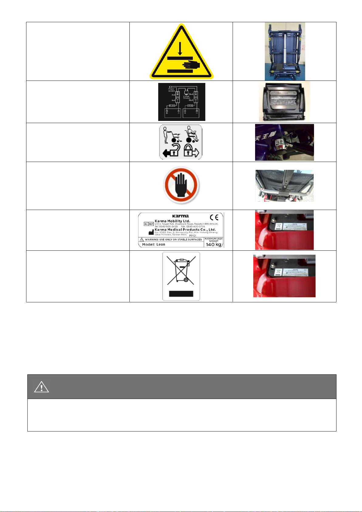
10. The Morgan Series Labeling
Please carefully read all the labeling on the wheelchair before driving it. Do not remove them. Protect
them for future reference.
Labeling
Location
[Circuit Breaker]
If this circuit breaker operates,
reset it by pushing the button.
[Finger-Pinch]
Avoid it when flip back the
armrest.
23
[Anti-Pinch Warning Label]
Be careful when the actuator is
active.
[Wiring Diagram]
Do not change the wiring.
[Freewheel Lever]
Follow the label to engage or
release it.
DO NOT TOUCH
11. EMI/RFI
This section provides the user with basic information about the problems with EMI, known sources of EMI
and protective measures either to reduce the possibility of exposure or to minimize the degree of
exposure. This section also shows some conditions in which unexpected or erratic wheelchair movements
may occur.
CAUTION
It is very important that you read this information regarding the possible effects of
electromagnetic interference on your powered KARMA wheelchair.

24
11.1 Electromagnetic interference from radio wave sources
Powered vehicles may be susceptible to electromagnetic interference (EMI), which is interfering
electromagnetic energy (EM) emitted from sources such as radio stations (Radio Frequency Interference),
TV stations, amateur radio (HAM) transmitters, two-way radios, and cellular phones. The interference (from
radio wave sources) can cause the powered vehicle to release its brakes, move by itself, or move in
unintended directions. It can also permanently damage the powered vehicle's control system. The intensity
of the interfering EM energy can be measured in volts per meter (V/m). Each powered vehicle can resist
EMI up to a certain intensity. This amount of resistance is called its immunity level. The higher the
immunity level, the greater the protection. At this time, current technology can achieve at least a 20 V/m
immunity level, which would provide useful protection from the more common sources of radiated EMI.
This powered vehicle model, with no further modification, has an immunity level of 20 V/m without any
accessories.
There are several sources of relatively intense electromagnetic fields in our everyday environment.
Some of these sources are obvious and easy to avoid. Others are not apparent, and exposure could be
unavoidable. However, we believe that by following the warnings listed below, your risk to EMI can be
greatly minimized.
11.2 The sources of radiated EMI can be broadly classified into three types:
Hand-held portable transceivers (transmitter-receivers) with the antenna mounted directly on the
transmitting unit, such as citizens band (CB) radios, walkie-talkies, security and fire or police transceivers,
cellular telephones and other personal communication devices.
NOTE:
Some cellular telephones or similar devices transmit signals while they are ON, even though
they are not in use.
Medium-range mobile transceivers used in police cars, fire trucks, ambulances and taxis usually having the
antenna mounted on the outside of the vehicle; and Long-range transmitters and transceivers, such as
commercial broadcast transmitters (radio and TV broadcast antenna towers) and amateur (HAM) radios.
NOTE:
Other types of hand-held devices (cordless phones, laptop computers, AM/FM radios, TV sets,
CD players, cassette players, and small appliances such as electric shavers and hair dryers, etc.)
So far as we know, are not likely to cause EMI problems.
11.3 Powered vehicle electromagnetic interference (EMI)
Because EM energy rapidly becomes more intense as one moves closer to the transmitting antenna
(source), the EM fields from hand-held radio wave sources (transceivers) are of special concern. It is
possible to unintentionally bring high levels of EM energy too close to the powered vehicle's control system

25
while using these devices. This can affect your powered vehicle's movement and braking. Therefore, the
warnings listed below are recommended to prevent possible interference with the control system of the
powered vehicle.
11.4 Warnings
Electromagnetic interference (EMI) from sources such as radio and TV stations, amateur radio (HAM)
transmitters, two-way radios and cellular phones can affect powered vehicles and motorized wheelchairs.
Following the warnings listed below should reduce the chance of unintended brake release or powered
vehicle movement which could result in serious injury.
Do not operate hand-held transceivers-receivers such as citizens band (CB) radios or turn ON personal
communication devices such as cellular phones, while the powered vehicle is turned ON.
Be aware of nearby transmitters, such as radio or TV stations, and try to stay away from them.
If unintended movement or brake release occurs, turn the powered vehicle OFF as soon as it is safe.
Be aware that adding accessories/components or modifying the powered vehicle may make it more
susceptible to EMI. There is no easy way to evaluate their effect on the overall immunity of the powered
vehicle.
Report all incidents of unintended movement or brake release to your powered vehicle dealer or KARMA
and note whether there was a source of EMI nearby.
CAUTION
Some stores may have automatic (sensor) doors and alarm systems set at certain frequencies
that might affect your powered wheelchair.
26
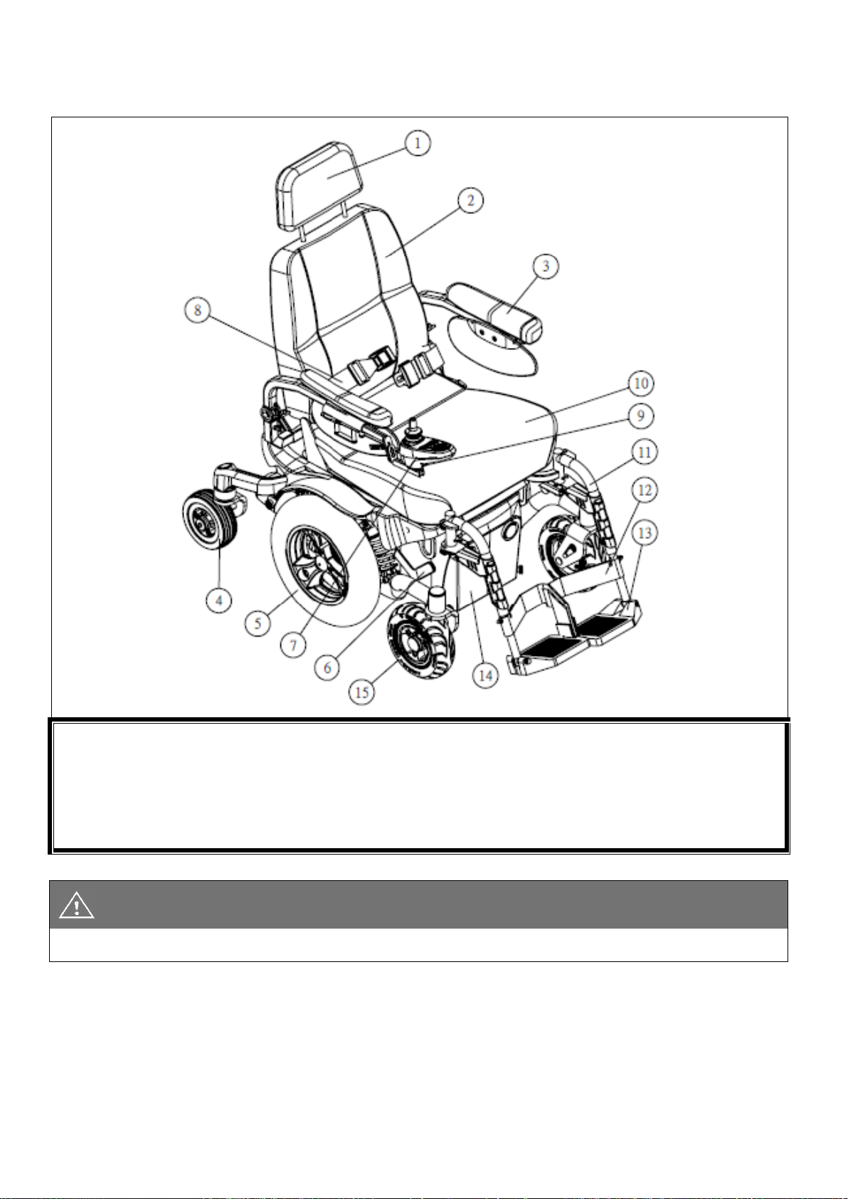
12. The wheelchair parts.
12.1 Morgan with Captain seat
1. Headrest
2. Captain Seat (Backrest)
3. Armrest
4. Rear Wheel
5. Mid drive wheel
6. Free wheel lever
7. Joystick controller
8. Positioning belt
9. Charger socket
10. Captain seat
11. Legrest
12. Calf belt
13. Footplate
14. Battery box front
The Captain seat has flip up, height adjustable armrests. The height adjustable footrests can swing away
sideways and can be taken off. the backrest can be manually set to different angles.
CAUTION:
Standard equipment are subject to change without notice.

27
1. Armrest width knob
2. Rear indicator (optional)
3. Rear battery box
4. Rear light (optional)
5. Front tie-down loop
The Morgan chassis has transportation loops in the front and rear, which can be used in combination with a
4-point tie down restraint system. Both front and mid drive-wheels can either be selected as solid or air
filled tyres. The rear caster wheels are solid. Additionally, the tyres are available in grey or black. The LED
lights in the front and rear provide a clear and bright light. Indicators are also intergraded into the light
system. The battery compartment can hold up to 50 Ah batteries for a good autonomy drive range.
Its six-wheel independent suspension is adjustable to ensure a comfortable and safe drive.
CAUTION:
Standard equipment is subject to change without notice.
5

28
12.2 Morgan with Sling seat
1. Headrest(optional)
2. Sling Seat (Backrest)
3. Armrest
4. Pelvic Belt
5. Rear caster Wheel
6. Mid drive wheel
7. Front caster wheel
8. Side Panel
9. Joystick controller
10. Charger socket
11. Sling seat
12. Legrest
13. Calf belt
14. Footplate
The Sling seat has flip up, height adjustable armrests. The height adjustable footrests can swing away
sideways and can be taken off. the backrest can be manually set to different angles. Its seat cushion and
soft backrest provides a comfortable sit.
CAUTION:
Standard equipment is subject to change without notice.

29
12.3 Morgan with KISS Seat
1. Headrest(optional)
2. Backrest
3. Armrest
4. Pelvic Belt
5. Rear caster Wheel
6. Mid drive-wheel
7. Controller (Joystick)
8. Charger socket
9. KISS seat cushion
10. Legrest
11. Footplate
12. Front caster wheel
The KISS seat is a modular, multi adjustable seating systems which can provide optimal seat comfort and
support. it has the option for a power cline backrest with biomechanical shear reduction. Its armrests are
fully adjustable in height, angle and can also be flipped up for an easy transfer. Different seat cushions
shapes and size are available. Also, the backrest has different option to choose from.
CAUTION:
Standard equipment are subject to change without notice.

30
13. Operation.
Except the joystick control panel can be operate by the occupant, other operations should be carried out by
an assistant. Anything wheelchair related that requires tools should be done by your authorized Karma
service provider.
13.1 Controller cable tie location.
The controller for the Morgan series is packaged in the carton; after opening the carton, the controller
needs to be equipped to the correct position by fastening two screws.
In the case that the controller cable ties become loose, please refer to the below figure for the locations to
fasten the cable ties, and follow the instructions:
1. At Section A (see the figure below), loosen the cable and leave some of the cable hanging because it
facilitates the armrest height adjustment.
2. At Section B (see the figure below), cross the cable tie around the screw. It provides better fixation and
keeps the cable tie from sliding out of place.
3. The other areas circled also indicates the cable tie locations.
Controller Cable Tie Locations
CAUTION:
The controller cable must be fixed as instructed above, otherwise the cable could be damaged and
cause malfunction of the wheelchair.

31
13.2. How to operate your wheelchair.
13.3. VR2 Controller:Control panel with lighting control.
13.3.1. Power ON/OFF
Press the power button. Be sure not to touch the joystick while turning on the controller. Your battery &
diagnostics indicator should light up. (See Figure 5-1 and Figure5.2)
13.3.2. Locking / Unlocking
The VR2 control system can be locked to prevent unauthorized use. The locking method is via a sequence of
key presses and joystick movements, as detailed next:
CAUTION:
Never tighten the cable ties to tight. This will damage the internal cores of the wires and can cause
the wheelchair to fail.
without Actuators
With Actuators
Control Panel (Figure 5-1)
Control Panel (Figure 5-2)
1. Battery Gauge
2. ON/OFF Button
3. Headlight / Taillight Indicator
4. Horn Button
5. Headlight / Taillight Button
6. Speed Indicator
7. Speed Increase Button
8. Right Turn Signal Indicator
9. Right Turn Signal Button
10. Hazards Indicator
11. Hazards Button
12. Speed Decrease Button
13. Left Turn Signal Indicator
14. Left Turn Signal Button
15. Seat Function Button
16. Tilt and Recline Indicators

32
To lock the wheelchair:
1. While the control system is switched on, depress and hold the on/off button.
2. After one second the control system will beep. Now release the on/off button.
3. Deflect the joystick forwards until the control system beeps.
4. Deflect the joystick in reverse until the control system beeps.
5. Release the joystick, there will be a long beep.
6. The wheelchair is now locked.
To unlock the wheelchair:
1. Use the on/off button to switch the control system on. The maximum speed / profile indicator will be
rippling up and down.
2. Deflect the joystick forwards until the control system beeps.
3. Deflect the joystick in reverse until the control system beeps.
4. Release the joystick, there will be a long beep.
5. The wheelchair is now unlocked.
6. Adjusting the Driving Speed.
13.3.3. Adjusting the driving speed:
The user can adjust the wheelchair′s top speed to suit their preferences and environment. The currently
selected top speed is shown on the Speedometer and can be adjusted using the ″Increase Speed″ and
“Decrease Speed” buttons. In the “5 speed” mode pressing the Increase Speed and Decrease Speed
buttons steps between one of five top speeds 20% to 100%. In the “fine adjusting” mode pressing and
holding the Increase Speed (Decrease Speed) Button ramps the top Speed up (down) in fine steps.
Speed indication:
Speed Scale
Speed Equivalencies and Recommended Circumstances
1-2
-Speed equivalent to walking slowly on foot
-On an decline
-Driving indoors or in a narrow space
3-4
-Equivalent to walking at a normal speed
-Driving outdoors on flat ground
5
-Speed equivalent to a brisk walk
-Driving in an open space
-On an incline
CAUTION
Please slow down before you get used to control your powered wheelchair.
Please slow down your speed when using it indoor.
The controller unit is set to ensure that the chair can give its best performance. Should the setting be
adjusted due to medical needs, the adjustment should be made by KARMA dealers. Do not change or
adjust the wiring layout of the chair for your safety.
Please slow down your speed when using it indoor.

33
13.3.4. Accelerating
To start driving the whellchair, slowly move the joystick out of centre into the direction you want to drive.
The more you move the joystick out of centre, the faster the wheelchair will drive. hold the joystick steady
in its position when the required speed has been reached.
13.3.5. Slowing down and stop:
Release the joystick and the electromagnetic brake will stop the wheelchair. Make sure that the wheelchair
has come to a complete stop before turning the power OFF. If you want to slow don wmore gently, just
move the joustick back intop the neutral midd position slowly. This way you can set the decelleration
exaclty the way you prefer.
CAUTION
The stopping distance will vary with your forward/reverse speed. Therefore, please gradually slow
down and come to a complete stop well before any obstacles or danger.
To park the wheelchair, be sure to park on flat ground and then turn the power to OFF.
NEVER use the freewheel mode when going down an incline.
The electromagnetic brake won't function in freewheel mode.
13.3.6. Turn Signal (Indicator Light)
The signal light will flash if you press the right or left signal button.
Turn off the signal light by pressing the button again.
13.3.7. Lights
To turn the lights on, press the light button. Press the light button again to turn the lights off.
13.3.8. Warning Signal(Hazards Light)
To turn the Hazards Indicator on, press the Hazards Button. Press the Hazards Button again to turn the
hazards function off.
CAUTION
Turn off the lights when not in use to save battery power.
13.3.9. Horn Button
The horn will sound for as long as the button is pressed.

34
13.3.10. Battery Gauge
The Battery Gauge is used to indicate power on and provides an estimate of the remaining battery capacity.
Any green LEDs lit indicate well-charged batteries. If only amber and red LEDs are lit, the batteries are
moderately charged. Recharge before undertaking a long trip. If only red LEDs are lit, the batteries are
running out of charge. Recharge as soon as possible.
13.3.11. Tilt and recline operation button
For Morgan VR2 with Captain Seat: Manual Reclining
For Morgan VR2 with Sling seat: Powered Tilt + Powered Reclining
For Morgan VR2 with KISS seat: Powered Tilt + Powered Reclining
Tilt operation
1. Turn the power on
2. Press the Seat Function Button once to toggle the control unit from Drive mode to Seat mode. Powered
tilt or recline function will be active as the Tilt Indicators or Recline Indicators are on.
3. Moving the joystick backward to tilt or recline the seat. The maximum tilting angle is 20°.
4. Moving the joystick forward will tilt or recline the seat towards the upright position.
Powered Reclining Operation
1. Turn the power on
2. Press the seat function bButton and move the joystick right. (moving the joystick left/right while in Seat
Mode toggles between Tilting Function and Reclining Function . Pressing the seat function button again
puts VR2 back in drive mode. 3 presses are a complete cycle)
3. Move the joystick backward to set the backrest angle.
4. Move the joystick forward tilt the backrest in that direction.

35
13.4 R-net control system
The R-net control system has two versions of Joystick Module – with and without lighting control. Most of
the controls are common to both however, the lighting buttons are only included on the Joystick Module
with lighting control. Each of the controls is explained within this section.
13.4.1. Joystick
The primary function of the joystick is to control the speed and direction of the wheelchair. The further you
push the joystick from the center position the faster the wheelchair will move. When you release the
joystick, the brakes are automatically applied.

36
If the wheelchair is fitted with actuators, the joystick can also be used to move and select actuators.
13.4.2. Communication cable
This cable connects the joystick module to the electronics.
13.4.3. Charger socket
The charger socket is used to connect the battery charger for charging the wheelchairs batteries. the
charger socket can also be used to lock the wheelchair with a hardware key. See the chapter about locking
and unlocking for detailed information.
13.4.4. R-net joystick module buttons
13.4.5. On/Off Button
The On/Off button applies power to the control system electronics, which in turn supply power to the
wheelchair’s motors. Do not use the On/Off button to stop the wheelchair unless there is an emergency. (If
you do, you may shorten the life of the wheelchair drive components).
13.4.6. Horn Button
The Horn will sound while this button is depressed.

37
13.4.7. Speed Decrease Button
This button decreases the maximum speed setting. Depending on the way the control system has been
programmed, a momentary screen may be displayed when the button is pressed.
13.4.8. Speed Increase Button
This button increases the maximum speed setting. Depending on the way the control system has been
programmed, a momentary screen may be displayed when the button is pressed.
13.4.9. Mode Button
The Mode button allows the user to navigate through the available operating Modes for the control system.
The available modes are dependent on programming and the range of auxiliary output devices connected
to the control system.
13.4.10. Profile Button
The Profile button allows the user to navigate through the available Profiles for the control system. The
number of available Profiles is dependent on how the control system is programmed. Depending on the
way the control system has been programmed a momentary screen may be displayed when the button is
pressed.
13.4.11. Hazard Warning Button and LED
This button activates and de-activates the wheelchair’s hazard lights. Depress the button to turn the
hazards on and depress the button again to turn them off. When activated the hazard LED and the indicator
LEDs will flash in sync with the wheelchair’s indicators.
13.4.12. Lights Button and LED
This button activates and de-activates the wheelchair's lights. Depress the button to turn the lights on and
depress the button again to turn them off. When activated, the lights LED will illuminate.
13.4.13. Left Indicator Button and LED
This button activates and de-activates the wheelchair’s left indicator. Depress the button to turn the
indicator on and depress the button again to turn it off. When activated, the left indicator LED will flash in
sync with the wheelchair’s indicator(s).

38
13.4.14. Right Indicator Button and LED
This button activates and de-activates the wheelchair’s right indicator. Depress the button to turn the
indicator on and depress the button again to turn it off. When activated, the right indicator LED will flash in
sync with the wheelchair’s indicator(s).
13.4.15. External On/Off Switch Jack
This allows the user to turn the control system on and off using an external device, such as a buddy button.
13.4.16. External Profile Switch Jack
This allows the user to select Profiles using an external device, such as a buddy button. To change the
Profile whilst driving simply press the button. If the control system is set to latched drive or actuator control
operation, then the polarity of the jack input is reversed to affect a failsafe system; meaning this input will
provide an External Profile Switch function and an Emergency Stop Switch function.
CAUTION
The Joystick Module is supplied with rubber bungs that must be inserted into the Jack Socket
when no external device is connected.
13.4.17. LCD Screen
The status of the control system can be understood by observing the LCD screen. The control system is
on when the screen is backlit.
CAUTION
The control system's warranty will be voided if any device other than a battery charger supplied,
with the wheelchair, the lock keyor Karma’s own USB charger is connected into this socket.
WARNING
Do not put fingers or clothes under the seat or backrest while seat functions are operated.

39
WARNING
DO NOT tilt the wheelchair on inclines or wet, slipery, icy or oily surfaces. Only tilt the
wheelchair on flat surfaces, otherwise it might cause injury to the user.
CAUTION
The speed will be reduced to half while the seat is tilted at around 7°. The powered wheelchair
can not be driven while the seat is tilted over 15°.
Do not put fingers or clothes under the seat or backrest while seat functions are operated.
SUGGESTION
It is recommended that you charge the batteries immediately when the battery indicator shows
only three or fewer signals.
After charging or replacing new batteries, drive the wheelchair for 2-3 minutes to make sure the
batteries are fully charged before going on a long journey.
In wintertime, the batteries may respond slowly and the drive range may also be reduced. You
must store your wheelchair indoors above freezing temperatures.
When driving on an incline, the battery indicator light might move up and down. This is normal.
Even if the batteries are used properly their capacity will decay over time, thereby reducing the
drive range (maximum distance traveled per full charge). Thus, when the drive range becomes
about 50% of what brand new batteries would offer, it's time to replace them with new
batteries. Otherwise, the batteries may die unexpectedly leaving you in a possibly precarious
situation. The drive range will be shortened when driving frequently on slopes or uneven
ground or over curb, as this consumes more battery power.

40
14. Chassis
14.1. Freewheel Lever
The Morgan series is supplied with freewheel lever devices to allow manual pushing of the powered
wheelchair if required. The freewheel lever is at the axle of the rear wheels.
Freewheel Mode: Turn both left and right-side lever down to the upmost position. The wheelchair will now
roll freely.
Drive Mode: Turn both levers upwards to the highest position. The wheelchair can be driven by motor
power. Ensure the lever is at the drive mode position.
CAUTION
Always ensure that the wheelchair is in Drive Mode before using the wheelchair. (i.e. Before
turning on the controller). When the wheelchair is in Freewheel Mode, make sure that there's an
attendant that can offer assistance.
14.2. Tyres
The rear wheels and the casters are pneumatic tires or solid PU filled tyres. Please, refer to the tires
pressure specified on the tire walls to maintain the tires at the correct pressure. Do not let anyone touch
the wheels when the wheelchair is in motion to avoid pinch injury.
CAUTION
always ensure the tyres pressure is okay. To low tyres pressure or uneven tyre pressure can
influence the driving characteristics and control of the wheelchair dramatically.

41
15 How to Adjust Your Wheelchair
15.1 The footrests
The Morgan series can be mounted with several types of KARMA footrests.
15.1.1. Swing-Away and Detach Footrest
To swing away and detach the footrests, pull the swing-away lever (Figure 5.3.1-1), then you can swing
away and/or detach the footrests. (Figure 5.3.1-2) It can make transferring in and out of the wheelchair
easier.
Figure 5.3.1-1
Figure 5.3.1-2
Figure 5.3.1-3
Figure 5.3.1-4
15.1.2. Vertical Swing-away Footrest
To swing away and detach the footrests, pull the swing-away lever (Figure 5.3.1-3), then you can swing
away and/or detach the footrests. (Figure 5.3.1-4) It can make transferring in and out of the wheelchair
easier.
15.1.3. Stump Footrest
The stump footrest is shown as Figure 5.3.1-5 To swing away and detach the footrests, pull the swing-away
lever (Figure 5.3.1-6), then you can swing away and/or detach the footrests. (Figure 5.3.1-7) It can make
transferring in and out of the wheelchair easier.
Use the #13 box end Wrench to loosen the bolt on the top of L-shape tube. (Figure 5.3.1-8) Adjust the
footrest height and re-tighten the bolt.
Figure 5.3.1-5
Figure 5.3.1-6
Figure 5.1.3-7

42
Figure 5.3.1-8
Figure 5.3.1-9
Figure 5.3.1-10
15.1.4. Elevating & Swing away Footrest
Elevating & Swing away Footrest is shown as Figure 5.3.1-11. To swing away and detach the footrests,
pull the swing-away lever (Figure 5.3.1-12), then you can swing away and/or detach the footrests.
(Figure 5.3.1-13) It can make transferring in and out of the wheelchair easier.
Footrest angle adjustment
Raise the footrest to an appropriate angle to accommodate the user's leg position and flexibility. (Figure
5.3.1-14)
Before descending the footrest, be sure to hold it and prevent it from dropping suddenly. Press the release
lever and lower the footrest. (Figure 5.3.1-15)
Calf support adjustment
Use the #3 Allen Key Wrench to remove the screws behind the calf support. Adjust the calf support to
accommodate the user's leg position and flexibility. (Figure 5.3.1-16) Re-tighten the screws.
Figure 5.3.1-11
Figure 5.3.1-12
Figure 5.1.3-13
Figure 5.1.3-14
Figure 5.1.3-15
Figure 5.1.3-16

43
15.1.5. Powered Elevating & Swing away Footrest
Powered Elevating & Swing away Footrest is shown as Figure 5.1.3-17. To swing away and detach the
footrests, pull the swing-away lever (Figure 5.1.3-18), then you can swing away and/or detach the footrests.
(Figure 5.1.3-19) It can make transferring in and out of the wheelchair easier.
Calf support adjustment
Use the #5 Allen Key Wrench to loosen the screw and adjust the calf support to accommodate the user's
leg position and flexibility. (Figure 5.1.3-20) Re-tighten the screws.
Use the #6 Allen Key Wrench to remove the screw and adjust the calf support forwards or backwards.
(Figure 5.1.3-21) Re-tighten the screws.
Use the #3 Allen Key Wrench to remove the screws behind the calf support and adjust the calf support up,
down, left or right. (Figure 5.1.3-22) Re-tighten the screws.

44
Moving the powered legrest electrically
Select footrest adjustment form the controller screen. (Figure 5.1.3-23) Raise or lower the footrest to an
appropriate angle by operating the joystick. (Figure 5.1.3-24, Figure 5.1.3-25)
Figure 5.1.3-17
Figure 5.3.1-18
Figure 5.1.3-19
Figure 5.1.3-20
Figure 5.3.1-21
Figure 5.3.1-22
Figure 5.3.1-23
Figure 53.1-24
Figure 5.3.1-25
Footrest Adjustment in Longitudinal (Fore/Aft) Position
For Sling seat and Captain seat
Please use the #4 Allen Key Wrench included in your KARMA Tool Kit to make this adjustment. Remove the
screws under the seat (Figure 5.3.2-1) then adjust the footrest to accommodate the user's leg position and
flexibility (Figure 5.3.2-2). Re-tighten the screws.

45
Figure 5.3.2-1
Figure 5.3.2-2
For KISS seat
Please use the #5 Allen Key Wrench to make this adjustment. Remove the screws under the seat (Figure
5.3.2-3) then adjust the footrest to accommodate the user's leg position and flexibility (Figure 5.3.2-4).
Re-tighten the screws.5.3.2.2.2 The procedures to adjust the powered footrest are the same as those
described on 5.3.2.2.1. Make sure the cable is properly routed and fastened after adjusting the footrest.
(Figure 5.3.2-5)
Figure 5.3.2-3
Figure 5.3.2-4
Figure 5.3.2-5
Footplates Adjustment
The footplate length should be adjusted according to the user's calf length. Go to your service provider for
adjustment or follow below instructions:
Standard Footplate
Use the #13 box end Wrench to loosen the bolt at the side of the footplate. Adjust the footplate height and
re-tighten the bolt. (Figure 5.3.3-1)
Figure 5.3.3-1

46
Tube-in-center Footplate
Use the #4 Allen Key Wrench and the #10 box end Wrench to loosen the bolt. (Figure 5.3.3-2) Adjust the
footplate height and re-tighten the bolt. (Figure 5.3.3-3, Figure 5.3.3-4)
Figure 5.3.3-2
Figure 5.3.3-3
Figure 5.3.3-4
Angle and Depth Adjustable Footrest
Use the #4 Allen Key Wrench and the #10 box end Wrench to loosen the bolt. (Figure 5.3.3-2) Adjust the
footplate height and re-tighten the bolt. (Figure 5.3.3-3), Figure 5.3.3-4)
Use the #4 Allen Key Wrench to loosen the screws. (Figure 5.3.3-5) Adjust the footplate left, right, forwards
or backwards. Re-tighten the bolt. (Figure 5.3.3-6)
Use the #17 box end Wrench to loosen nut A. After adjusting the footplate angle, tighten screw B and nut A.
(Figure 5.3.3-7)
Angle Adjustable Footplate
Angle Adjustable Footplate is shown as Figure 5.3.3-8. Use the #4 Allen Key Wrench and the #10 box end
Wrench to loosen the bolt. (Figure 5.3.3-9) Adjust the footplate height and re-tighten the bolt.
Use the #5 Allen Key Wrench to loosen the screw. After adjusting the footplate angle, re-tighten it. (Figure
5.3.3-10)

47
Figure 5.3.3-8
Figure 5.3.3-9
Figure 5.3.3-10
Center Mount Legrest Assembly
When adjusting the footplate upwards or downwards for the needs of the user, use the #6 Allen Key
Wrench to loosen the bolt. (Figure 5.3.4-1) After adjusting the footplate, re-tighten the bolt.
When adjusting the footplate inwards or outwards for the needs of the user, use the #17 box end Wrench
to loosen the nut. (Figure 5.3.4-2) and use the #5 Allen Key Wrench to adjust the bolt.
Flip the footplate over to check whether it is located at appropriate angle. The adjustable range is between
0° and 15°. After adjusting the footplate, re-tighten the nut.
When adjusting the whole footplate assembly angle for the needs of the user, use the #5 Allen Key Wrench
to loosen the bolts on both sides. (Figure 5.3.4-3) The adjustable angle is-5°, 0°, 5°, 10° and 15°. Ensure the
footplate assembly does not interfere with other parts. The adjustable angle also dependents upon the
type of the seat.
Adjusting the Calf Pad
When adjusting the calf pad upwards, downwards, forwards or backwards, use the #5 Allen Key Wrench to
loosen the four bolts on both sides. (Figure 5.3.4-4) After adjusting the calf pad to the appropriate position,
re-tighten the bolts.
When adjusting the calf pad leftwards or rightwards, use the #4 Allen Key Wrench to loosen the bolts.
(Figure 5.3.4-5) After adjusting the calf pad to the appropriate position, re-tighten the bolts.
.
CAUTION
When adjusting the footrest or footplate, ensure the user's feet are appropriately supported.

48
Figure 5.3.4-1
Figure 5.3.4-2
Figure 5.3.4-3
Figure 5.3.4-4
Figure 5.3.4-5
15.2. Armrest height adjustment
Morgan with Sling Seat
In order to position the user's arms and shoulders correctly, the armrests are djustable in height by 7 cm
from 18 cm above the seat rail to 25 cm.
Use the #5 Allen Key Wrench from KARMA Tool Kit to loosen the height adjustment bolts under the armrest
pad (Figure 5.3.5-1). Adjust the armrest to the proper height. Finally, re-tighten the bolts. (Figure 5.3.5-2)
Figure 5.3.5-1
Figure 5.3.5-2
Morgan with KISS seat
Detachable T-Armrest set adjustment
Detachable T-Armrest set is shown as Figure 5.3.5-3. The whole armrest assembly can be removed by
releasing lever A. (Figure 5.3.5-4)
Use the #4 Allen key wrench to loosen the screws. Adjust the armrest forwards or backwards. Re-tighten
the screws. (Figure 5.3.5-5)
By releasing lever B, the height of the armrest can be adjusted, and the armrest pad assembly can be
removed. (Figure 5.3.5-6)
Use the #3 Allen key wrench to loosen the screws under the armrest pad. Adjust the armrest pad forwards
or backwards. Re-tighten the screws. (Figure 5.3.5-7)

49
Figure 5.3.5-3
Figure 5.3.5-4
Figure 5.3.5-5
Figure 5.3.5-6
Figure 5.3.5-7
Flip back armrest assembly
The flip Back armrest assembly of KISS seat is shown as Figure 5.3.6-1
Press the spring button and flip the armrest back. (Figure 5.3.6-1)
When adjusting the whole armrest assembly upwards or downwards, use the #4 Allen Key Wrench and the
#10 box end Wrench to loosen the screw used to fixing the armrest bracket. (Figure 5.3.6-2)
When adjusting the armrest pad upwards or downwards, use the #4 Allen key wrench to loosen the screw
used to fixing the armrest frame. (Figure 5.3.6-3)
When adjusting the whole armrest pad assembly forwards or backwards, use the #4 Allen Key Wrench to
loosen the screw used to fixing the armrest adjustable frame. The total range of adjustment is 5cm ,in
increments of 2.5 cm. (Figure 5.3.6-4)
When adjusting the armrest pad forwards or backwards, use the #3 Allen key wrench to loosen the screw
used to fixing the armrest pad. The total range of adjustment is 5cm, in increments of 2.5 cm.
(Figure 5.3.6-5).
In order to keep the armrest pad horizontal, the flip back armrest assembly might need to be adjusted
together with the backrest angle according to table 6-1 and table 6-2. (Figure 5.3.6-7) When adjusting the
angle of the flip back armrest, use the #4 Allen key wrench to loosen the screws used to fixing the
adjustable plate. (Figure 5.3.6-6).

50
Figure 5.3.6-1
Figure 5.3.6-2
Figure 5.3.6-3
Figure 5.3.6-4
Figure 5.3.6-5
Figure 5.3.6-6
Figure 5.3.6-7
Table 6-1 Armrest angle adjustment table
Table 6-2 Back pad angle adjustment table
Flip-Back Reclining Armrest
Flip-Back reclining armrest is shown as Figure 5.3.7-1
By pulling the lock pin and turning it in 90 degree, the armrest can be lifted backwards. (Figure 5.3.7-2)

51
Figure 5.3.7-1
Figure 5.3.7-2
When putting the armrest back to the working position, be sure part A is properly inserted into part B. Turn
the lock pin in 90 degree and make sure the armrest is properly installed. (Figure 5.3.7-3).
Use the #4 Allen Key Wrench and the #10 box end Wrench to remove the screws. Adjust the armrest height
and re-tighten the screws. (Figure 5.3.7-4).
Use the #5 Allen Key Wrench to loosen the screw. Adjust the base block forwards or backwards and retighten the screw. (Figure 5.3.7-5).
Use the #4 Allen Key Wrench and the #10 box end Wrench to remove the screws and nuts. Adjust the
armrest to accommodate the user's arm position and flexibility (Figure 5.3.7-6). Re-tighten the screws.
Use the #3 Allen Key Wrench to loosen the screws. Adjust the armrest pad forwards or backwards and retighten the screw. (Figure 5.3.7-7).
Recline the seat by operating the joystick after completing all of the adjustments. Be sure the movement of
armrest is proper and smooth.
Figure 5.3.7-3
Figure 5.3.7-4
Figure 5.3.7-5
Figure 5.3.7-6
Figure 5.3.7-7
Figure 5.3.8-1

52
15.3. Seat Depth and seat width adjustment
Morgan with Sling Seat (Seat Depth Adjustment)
Use the #13 box end Wrench from KARMA Tool Kit to loosen the two bolts under the seat. Remove the
bolts on the other side. (Figure 5.3.8-1).
There are two evenly spaced holes for incremental adjustments which is in increments of 25.4 mm (1”). The
total range of adjustment is 50 mm. (Figure 5.3.8-2).
Move the seat forward or backward to the desired position.
Re-tighten the bolts.
Figure 5.3.8-2
Morgan with KISS Seat (Seat Depth Adjustment)
The KISS seat is shown as Figure 5.3.8-3.
Use the #4 Allen Key Wrench to loosen the screws A and remove the screw B on both sides of the backsupport frame. Adjust the base plate forwards or backwards to accommodate the user's needs. (Figure Retighten the screws.
The rails for adjusting the seat depth can be dived into two types, one for adults and the other for children.
(Figure 5.3.8-5). The adjustable range is shown as below.
Adults:41,43.5,46,48.5,51 (cm)
Children:31,33.5,36,38.5,41 (cm)
Use the #4 Allen Key Wrench to loosen the screws behind the back support. Adjust the back-support
forwards, backwards or at an angle to accommodate the user's needs. (Figure 5.3.8-6). Re-tighten the
screws.
CAUTION
Adjusting the seat depth will change the center-of-gravity position. For your safety, contact your
KARMA wheelchair dealer for adjustment.

53
Figure 5.3.8-3
Figure 5.3.8-4
Figure 5.3.8-5
Figure 5.3.8-6
Morgan with KISS Seat (Seat width adjustment)
KISS Seat without Tilt and Recline Options
KISS Seat without tilt and recline options is shown as Figure 5.3.8-.7.
Use the #4 Allen Key Wrench to remove the screws A and the plate B. (Figure 5.3.8-8)
Use the #4 Allen Key Wrench to loosen the screws C. (Figure 5.3.8-9)
Use the #5 Allen Key Wrench to remove the screws D. Move part E and F inwards or outwards to adjust the
seat width in order to meet user's needs. Re-tighten all screws. (Figure 5.3.8-10)
When adjusting the back support width, be sure the number H in the window matches with the seat width
and both edges of the plate is in line with the marks G. (Figure 5.3.8-11) Re-tighten the screws C and the
torque is set at 10N/m or 88in/lb . (Figure 5.3.8-12)
The adjustable ranges can be divided into two groups, one for adults and the other for children.

54
(Figure 5.3.8-12, Figure 5.3.8-13)
Adults:41,43.5,46,48.5,51 (cm)
Children:31,33.5,36,38.5,41 (cm)
Figure 5.3.8-7
Figure 5.3.8-8
Figure 5.3.8-9
Figure 5.3.8-10
Figure 5.3.8-11
Figure 5.3.8-12
Figure 5.3.8-13
Figure 5.3.8-14
Figure 5.3.8-15
KISS Seat with Reclining Option
KISS Seat with recline option is shown as Figure 5.3.8-14.
The procedures to adjust the seat width are almost the same as those of KISS seat without tilting and
reclining options except step 5.3.8.11. Before adjusting the back-support width, remove the screws A.
(Figure 5.3.8-15)

55
15.4. Seat angle adjustment
Morgan Sling Seat with Tilting Function:
The initial seat angle is set at 2°. If the desired seat angle can be 5°, pull out the hair pin cotter and E Ring
from the lower hole (Figure 5.3.9-1) and insert them in the upper hole.
Figure 5.3.9-1
Figure 5.3.9-2
Morgan Sling Seat without Tilting Option
The initial seat angle is set at 2°. If the desired seat angle can be 5°, Loosen the screws at both the left side
and right side from the lower hole (Figure 5.3.9-2) and insert them in the upper hole.
Morgan KISS Seat with Tilting Option (Including seat height adjustment)
KISS Seat with Tilting option is shown as Figure 5.3.9-3.
Depending on the user's needs, check table 5-1 to see whether it is necessary to adjust the plates Ⅰ, Ⅱ, Ⅲ,
Ⅳ and Ⅴ. (Figure 5.3.9-4, Figure 5.3.9-8) If it necessary to adjust the adjustable seat height plate, carry out
the following steps. Use the #5 Allen Key Wrench to remove the screws from F3, C and P4 on both sides of
the seat base. Remove Plate Ⅳ. (Figure 5.3.9-4) Loosen the screw from P3. Remove the screw from R1 to
R2 if it is necessary. Re-tighten screws P3 and R1 or R2 according to table 5-1. (Figure 5.3.9-5) Put Plate Ⅳ
and the screw back P4, but do not tighten it yet. Use the #5 Allen Key Wrench to loosen the screws from P,
C and P2 on both sides of the seat base. Remove the screw from C to A, B or D if it is necessary. Re-tighten
screws. (Figure 5.3.9-6) According to table 5-1, Replace screws on plate plates Ⅳ (A, B, C or D) and
plateⅤ(F1, F2, F3, F4, F5 or F6). Re-tighten all screws. (Figure 5.3.9-4) Ensure all screw are properly
tightened.
Figure 5.3.9-3

56
Figure 5.3.9-4
Figure 5.3.9-5
Figure 5.3.9-6
Table 5-1 : Kiss seat with tilting function
Ⅰ Ⅱ Ⅲ
Ⅲ Ⅳ Ⅳ
Ⅴ
Seat Angle
Seat Height (Adult)
Seat Height
(pediatric)
1,B
R2
1,C
P5,F2
0
46.5
46.5
3,C
R2
1,B
P5,F1
0
49
49
2,A
R1
2,B
P5,F1
0
51
51
1,A
R2
1,B
P5,F3
3
51
50.5
2,A
R2
2,B
P5,F4
3
53.5
53
1,A
R2
1,C
P5,F2
6
52
51
3,B
R2
1,B
P5,F1
6
54
53
1,B
R2
1,B
P5,F3
-3
46
46.5
3,C
R2
2,A
P5,F5
-3
49
49.5
2,B
R1
2,A
P5,F3
-6
46.5
47.5

57
Morgan KISS seat without tilting option (Including seat height adjustment)
KISS Seat without Tilting option is shown as Figure 5.3.9-7.
Use the #5 Allen Key Wrench to loosen the screws from P, A and D on both sides of the seat base. (Figure 8)
Remove the screw from R2 to R1 according to table 5-2 if it is necessary. But do not tighten it so far.
Remove screw A to 1, 3 or 4 according to table 5-2. (Figure 5.3.8-9)
Re-tighten all screws.
Figure 5.3.9-.7
Figure 5.3.9-8
Figure 5-7.9

58
Table 5-2 : Kiss seat without tilting function
Ⅱ Ⅰ Ⅳ Ⅱ Ⅲ Ⅰ Ⅳ Ⅲ Ⅰ
Seat Angle
Seat Height (Adult)
Seat Height (pediatric)
P,F1
B,1
╳
E,1,R2
0
43.5
43.5
P,F1
A,2
2,R1
E,6/F,7
0
46
46
P,F1
A,4
2,R2
E,6/F,7
0
48.5
48.5
P,F2
A,4
1,R2
D,6/E,7
0
51
51
P,F1
B,1
╳
F,1,R2
3
45.5
45
P,F1
A,2
╳
D,1,R2
3
48
47.5
P,F1
A,4
3,R2
E,6/F,7
3
50.5
50
P,F2
A,4
2,R2
D,6/E,7
3
53
52.5
P,F2
B,2
╳
E,1,R2
6
49
48.5
P,F1
A,4
2,R1
E,6/F,7
6
51.5
51
P,F2
A,4
1,R1
D,6/E,7
6
54
53.5
P,F1
A,3
╳
E,1,R2
9
52
51
P,F2
A,3
2,R1
E,6/F,7
9
54
53
15.5. Backrest Angle Adjustment
Morgan with Captain Seat
The level for adjusting the backrest angle is at the left side in the lower back of the backrest.
(Figure 5.3.10-1)
Hold the backrest frame with one hand and adjust the backrest angle to your desired angle.
(Figure 5.3.10-2)
Release the level when the desired angle is reached. If the seat width is 18”, the angle can be adjusted from
0°~65°. If the seat width is 20”, the angle can be adjusted from 0°~45°.

59
Figure 5.3.10-1
Figure 5.3.10-2
Morgan with Sling Seat (Manual Recline)
Behind the backrest, there is an adjusting knob for at eat side of it. (Figure 5.3.10-3) Hold the backrest and
use a 13mm open end wrench to remove knobs and nuts. Adjust the backrest to the desired angle. ( Figure
5.3.10-4) Re-tighten knobs to fasten the backrest. The range of adjustable angle is between -1°~11°。
Figure 5.3.10-3
Figure 5.3.10-4
Morgan with KISS Seat(Manual Recline)
KISS Seat with manual reclining option is shown a Figure 5.3.10-5.
Remove nuts and knobs. Adjust the backrest angle to accommodate the user's needs. (Figure 5.3.10-6).
Re-tighten all nuts and knobs
Figure 5.3.10-5
Figure 5.3.10-6
Morgan with KISS Seat (powered Recline)
KISS Seat with powered reclining option is shown as Figure5.3.10-7.

60
Select reclining function from the control screen.
Recline the seat by operating the joystick. (Figure 5.3.10-8)
Figure 5.3.10-7
Figure 5.3.10-8
15.6. Headrest Adjustment
Morgan with Captain Seaty
Press the button below the headrest and adjust the location of headrest. (Figure 5.3.11-1 and 5.3.11-2)
Figure 5.3.11-1
Figure 5.3.11-2
Figure 5.3.11-3
Morgan with Sling Seat
Use the #4 Allen Key Wrench to loosen the screw below the headrest. There are four evenly spaced holes
for incremental adjustments. The total range of adjustment is 50 mm. (Figure 5.3.11-3). Adjust the headrest
to the desired position. (Figure 5.3.11-4, Figure 5.3.11-55, Figure 5.3.11-6, Figure 5.3.11-7)
Figure 5.3.11-4
Figure 5.3.11-5

61
Figure 5.3.11-6
Figure 5.3.11-7
Morgan with KISS Seat:
Adjustable head support is shown as Figure 5.3.11-8 and Figure 5.3.11-9.
Contour head support is shown as Figure 5.3.11-10 and Figure 5.3.11-11.
Use the #4 Allen Key Wrench to loosen the screws behind the head support. Adjust the headrest leftwards
or rightwards to the desired position. (Figure 5.3.11-12)
The head support can be removed by turning and loosening the lever A. ( Figure 5.3.11-13) When installing
the head support back to the back support, be sure the pin B is in alignment with the slot C. (Figure 5.3.1114, Figure 5.3.11-15) Turn and tighten the lever A.
Use the #3 Allen Key Wrench to loosen the screw D. The head support can be rotated or moved up or down.
(Figure 5.3.11-16)
Press the lever E. The head support can be folded. (Figure 5.3.11-17)
By turning and loosening the lever F, the head support can be moved forwards or backwards.
(Figure 5.3.11-18)
Use the #5 Allen Key Wrench to loosen the screw G. The head support pad can be adjusted.
(Figure 5.3.11.19)
Unzip the cover of the head support pad. Use the #5 Allen Key Wrench to loosen the screw H. The width of
head support can be adjusted. (Figure 5.3.11-20)
Figure 5.3.11-8
Figure 5.3.11-9
Figure 5.3.11-10
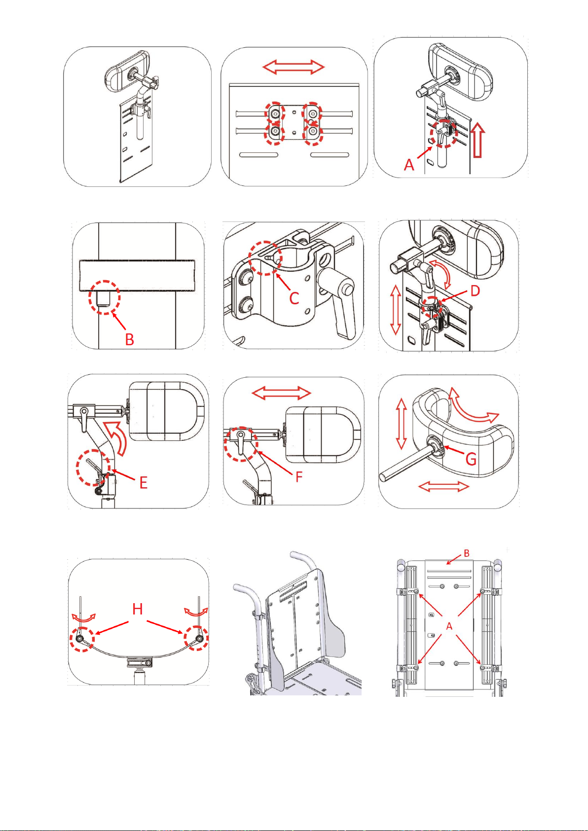
62
Figure 5.3.11-11
Figure 5.3.11-12
Figure 5.3.1-13
Figure 5.3.11-14
Figure 5.3.11-15
Figure 5.3.11-16
Figure 5.3.11-17
Figure 5.3.11-18
Figure 5.3.11-19
Figure 5.3.11-20
Figure 5.3.12-1
Figure 5.3.12-2

63
15.7. Back support Height Adjustment for KISS Seat
The back support is shown as Figure 5.3.12-1.
Use the #4 Allen Key Wrench to loosen the screws A. The plate B can be moved up or down for adjusting
back support height. Re-tighten all screws. (Figure 5.3.12-2)
Trunk Support Adjustment for KISS Seat
Trunk support is shown as Figure 5.3.13-1.
The trunk support can be removed from the seat by turning and releasing lever A. (Figure 5.3.13-2)
Upon pressing the shaft B, the trunk support can be swung outwards. (Figure 5.3.11-3)
Use the #4 Allen Key Wrench to loosen the screws C. The trunk support can be moved up or down. Retighten all screws. (Figure 5.3.13-4)
Use the #4 Allen Key Wrench to loosen the screws D. The trunk support can be moved forwards or
backwards. Use the #4 Allen Key Wrench to loosen the screws E. The trunk support can be moved leftwards
or rightwards. Re-tighten all screws. (Figure 5.3.13-5)
Figure 5.3.12-1
Figure 5.3.12-2
Figure 5.3.13-3
15.8. Hip Supports Adjustment for KISS Seat
Hip support is shown as Figure 5.3.14-1.
Upon pressing the shaft, A, the hip support can be swung outwards. (Figure 5.3.14-2)
Use the #4 Allen Key Wrench to loosen the screws B. The hip support can be moved forwards or backwards.
(Figure 5.3.14-3)

64
Use the #4 Allen Key Wrench to loosen the screws C. The hip support pad can be moved up or down. Retighten all screws. (Figure 5.3.14-4)
Several holes can be selected to adjust the horizonal position of the hip support pad. Use the #4 Allen Key
Wrench to remove the screws C. Move the hip support pad forwards or backwards. Re-tighten all screws.
(Figure 5.3.14-4)
Use the #4 Allen Key Wrench to loosen the screws D. The hip support pad can be moved up or down. Retighten all screws. (Figure 5.3.14-5)
Use the #4 Allen Key Wrench to loosen the screws E. The hip support pad can be rotated or moved inwards
or outwards.
Figure 5.3.14-1
Figure 5.3.14-2
Figure 5.3.14-3
Figure 5.3.14-4
Figure 5.3.14-5
Figure 5.3.14-6
15.9. Pommel Adjustment for KISS Seat
Pommel assembly is shown as Figure 5.3.15-1.
Upon pressing the shaft, A, the pommel can be swung outwards. (Figure 5.3.15-2)
Use the #4 Allen Key Wrench to loosen the screws B. The pommel can be moved leftwards or rightwards.
Re-tighten all screws. (Figure 5.3.15-3)
Loosen the knob C. The pommel can be moved forwards or backwards. Re-tighten all screws. (Figure
5.3.15-4)
Use the #4 Allen Key Wrench to loosen the screws C. The pommel pad can be moved up or down. Retighten all screws. (Figure 5.3.15-5)

65
Figure 5.3.15-1
Figure 5.3.15-2
Figure 5.3.15-3
Figure 5.3.15-4
Figure 5.3.15-5
15.10. Pelvic Belt Adjustment for KISS Seat
The pelvic belt is shown as Figure 5.3.16-1.
Use the #5 Allen Key Wrench and the #13 box end Wrench to remove the screw and nut. The pelvic belt can
be installed at point A, B or C. Re-tighten the screw. (Figure 5.3.16-2)
The pelvic belt can also be fixed at slot C to meet the user's needs. (Figure 5.3.16-2) In order to this
replacement, the M8 Phillips Flat Round Head Screw and Nylon Insert Hex Nut have to be replaced by a M6
Phillips Flat Round Head Screw and a Square Nut. (Figure 5.3.16-3, Figure 5.3.16-4)
Figure 5.3.16-1
Figure 5.3.16-2
Figure 5.3.16-3

66
Figure 5.3.16-4
16. Transferring in and transferring out of the powered wheelchair
16.1. Transferring in to the powered wheelchair
Engage the freewheel levers and make sure that the controller is turned off.
Flip up the footplates and swing the footrest to the side.
Lower the user into the seat and use the armrest for support.
Swing back the footrest and flip down the footplates so that the user can place his feet upon them.
Turn on the controller.
16.2. Transferring out of the powered wheelchair
Make sure that the chair is as close as possible to the place you're transferring to.
Engage the freewheel levers and make sure that the controller is turned off.
Flip-up the footplates and swing the footrests to the side.
Shift your body weight out of the wheelchair to the place you're transferring to.
16.3. Starting and Driving
Make sure the wheelchair is turned off.
Make sure the freewheel level is engaged.
Make sure the driver's seat is installed properly.
Make sure the armrests have been returned to the proper position.
Turn the power ON. If necessary, turn on the headlights and taillights.
Check the battery indicator and make sure there is enough power
for your trip(s). If you have any doubt about the remaining power, please charge the battery before you
depart.
Set the speed dial to the proper level.
Be sure the controller is in good condition.
Make sure the electromagnetic brake is in good working order.
Always make sure that your surroundings are safe to operate the wheelchair.

67
CAUTION
Do not turn the power OFF while driving, as this will lead to an abrupt stop and possible injury.
Do not set the speed dial on high while driving indoors.
Do not adjust the speed dial while driving. A sudden change to the highest speed may endanger
you and cause failure to your wheelchair.
Do not place magnetic devices near the controller, as this may affect the operation of your
wheelchair.
Be careful while driving in heavy traffic and crowded areas.
While reversing the vehicle be aware of the people and objects behind you.
If anti-tippers are standard equipped, DO NOT operate the wheelchair without anti-tippers being
installed. Anti-tippers MUST BE attached at all times.
16.4. Installing the seat assembly on the chassis.
WARNING
For your own security, read and obey all the instructions before proceeding the installation.
If the seat assembly and the chassis are packed in different package when delivered, follow the following
steps to install the seat:
16.4.1. Captain Seat
Put the captain seat on the chassis (1) and move it forwards (2). (Figure 5.3.19-1)
Ensure the bolt on the chassis to slide into the slot under the seat (1). (Figure 5.3.19-2)
Use one M10*35L button head hex socket screw, lock spring washer and flat washer to fix the seat (3) from
the front of the seat. (Figure 5.3.19-3)
Ensure the seat that is properly fastened on the chassis. You can lift the seat up to test if it’s loose. If, yes,
please tighten all bolts.
Connect the controller joystick connector under the seat (2). (Figure 5.3.19-2)
Install the right and left armrest, and the right and left footrest.
Figure 5.3.19-1
Figure 5.3.19-2
Figure 5.3.19-3

68
16.4.2. Sling Seat.
Needed parts:
Item
Photos
Description
Quantity
A Hex Head Shoulder Bolt
2
B Hex Nylon Dome Nut M8
2
C
Tie
1
D
Clevis Pin *60L
1
E M8*35LScrew+ M8 Nut
4
F
M8*16L Screw +Spring Washer
+ Flat Washer
2
G M6*20L Screw +Cup Washer
2
H M6*40L Screw +Cup Washer
2
I
E RING
1
Take the seat assembly out of the package. (Figure 5.3.19-4)
Erect the backrest to the upright position in order to make it easier to install the recline actuator. (Figure
5.3.19-5)

69
Figure 5.3.19-4
Figure 5.3.19-5
Figure 5.3.19-6
Insert the hex head shoulder bolt through the top hole of the recline actuator. Use hex Nylon dome nut to
fix the bolt. (Figure 5.3.19-6)
Use part C to tighten the cable of recline actuator on the Aluminum tube. (Figure 5.3.19-7)
CAUTION
Make sure the cable is properly routed to prevent it from being damaged or pulled when the
actuator is operated between the uppermost position and the lowermost position.
Figure 5.3.19-7
Take the tilt actuator and the fixing bracket out of the package. Insert the Clevis pin through the lower hole
on the rod of the tilt actuator. Insert E ring into the slot of the pin in order to fix the tilt actuator on the
fixing bracket. (Figure 5.3.19-8)
CAUTION
Part Clevis Pin shall be inserted into to the lower hole.
CAUTION
Do not insert part Clevis Pin into to the upper hole.

70
Figure 5.3.19-8
Figure 5.3.19-9
Cut the tie which is used to fasten the seat frame and the fixing base before installing the fixing bracket in
the fixing base. (Figure 5.3.19-9)
Use part E to fasten fixing bracket on the seat frame. There are four sets of screws and nuts. Two sets are
used for either side. (Figure 5.3.19-10)
Figure 5.3.19-10
Insert hex head shoulder bolt into the upper hole on the base of the tilt actuator. Use the hex Nylon dome
nut to fasten the bolt in order to fix the tilt actuator on the seat frame. (Figure 5.3.19-11)
Connect the connector of the tilt actuator to the connector fixed on the right side of the seat frame. (Figure
5.3.19-12)
Figure 5.3.19-11
Figure 5.3.19-12

71
Figure 5.3.19-13
Figure 5.3.19-14
Put the rear part of the seat assembly on the interface plate. (Figure 5.3.19-15)
Figure 5.3.19-15
Figure 5.3.19-16
Push the seat backwards and ensure the fixing pins on the interface plate are properly seated in the slots
under the seat frame. (Figure 5.3.19-16)
Use part F to fix seat frame. Make sure the two screws are properly tightened. (Figure 5.3.16-17)
CAUTION
Ensure the hex head shoulder bolt is installed at the correct position when installing the seat.
Use Loctite 243 when installing the bolt.
CAUTION
When installing a captain seat, the hex head shoulder bolt is installed at position A. (Figure
5.3.19-13)
CAUTION
When installing a sling seat, the hex head shoulder bolt is installed at position B. (Figure
5.3.19-14)

72
Figure 5.3.19-17
Connect cables of tilt actuator, recline actuator, speed limitation, angle limitation and the controller which
are under the seat. (Figure 5.3.19-18)
CAUTION
Ensure all cables are appropriately connected. Each can be identified by the color or the type of
connectors.
Figure 5.3.19-18
Use part G and H to fasten the seat plate on the seat frame. (Figure 5.3.19-19)

73
Figure 5.3.19-19
Reinstall new version of parameters of the controller.
Drive the wheelchair when the seat is reclined to the lowermost position. If the wheelchair is inhibited
from driving, please adjust the switch. (Figure 5.3.19-21)
CAUTION
In some situations, it could be not safe to recline or tilt the seat when driving on a slope. For
safety, the switch is used to inhibit the user from reclining or tilting the seat when driving on
the slope.
Figure 5.3.19-21
WARNING
After completing this installation, do operate the wheelchair to assure it works without
malfunctions.

74
17. Transportation.
17.1 transportation using a 4-point tie down webbing restraints.
The Morgan wheelchair is has been crash tested acording to the ISO7176-19-2008 crash test and suitable to
use as a seat in vehicles. KARMA however, would recommend that the user transfers to the vehicle seating
if possible.
The wheelchair must only be transported in a vehicle that is approved or adapted for such purposes. It is
safest if the wheelchair is separated from the driver’s compartment. Transportation in a trailer is also an
optional recommendation. Should the wheelchair be transported in an MPV/estate car or other vehicle, it
is vital that the wheelchair is properly fixed and that the fixing points of the car are well anchored. In all
situations of transportation, the wheelchair needs to be properly fixed using an ISO 10542-1 approved 4point heavy duty restraint, being able to withstand the mass of the wheelchair, in case of an accident or to
prevent the wheelchair from sliding or tilting while driving. Check that the wheelchair is properly fastened
and that the parking brakes are engaged. The wheelchair can be locked into position by using fastening
straps through the brackets in the front and the back, each marked with an indication sticker.
rear transportation loops front transportation loops
NOTE
The specifications of the wheelchair are in accordance with the requirements specified in ISO
7176-19-2008.
Secure the wheelchair according to the manufacturer of the vehicle restraint systems instructions. Always
make sure that the anchoring points on the transport vehicle, which are capable being able to withstand
the loads of the wheelchair, in case of an accident. Use of this is strongly advised since the heavy
wheelchair can cause serious problems in case of a car accident. The wheelchair fulfils al requirements
according to the ISO 7176-19:2008 standard (“Wheeled mobility devices for use in motor vehicles”).

75
NOTE
NOTE
The position belt of a wheelchair is not meant to be used as a car safety belt. It only prevents
the user from sliding out of the seat while driving the wheelchair. If a user is transported in his
wheelchair, he or she should wear an extra car safety belt, which is attached to the vehicle like
all the car safety belts.
NOTE
When shipped by boat, please give special attention to prevent contact with salt water or air.
Salt water is extremely corrosive and might lead to unwanted damage of the product.
Karma Medical Taiwan would always recommend transferring to a car seat within a vehicle,
however, should this not be possible, the following is the safest method:
a. The wheelchair must be positioned in a forward-facing position.
b. An ISO 10542-1 approved heavy duty WTORS (Wheelchair Tie down and Occupant Restraint System)
rated for the wheelchairs weight - must be used to secure the wheelchair and user during transportation
in a road vehicle.
c. The restraint system must be fixed on the specific points of the wheelchair, which show a label
of a transportation hook.
d. A head restraint system must be fitted during transportation. This device must be suitably
positioned and able to stay on during transportation.
e. The center point of gravity of the wheelchair during transportation should be as low as
possible. A powered seat elevator must be in its drive position, the backrest should be upright,
the seat should be in a horizontal position and the legrest should be positioned in
a normal seating positions.

76
17.2. transportation guideline.
The wheelchair has a 4-point heavy duty webbing restraint. Using
two brackets on the front end and two brackets on each rear side
of the chassis. The brackets are indicated with a sticker.
The angle of the straps should be according to the diagrams shown
below. This is in order to have maximum effect in vertical and horizontal
direction.
The straps must be connected to the vehicle at suitable anchor points. Make sure that the tire pressure is at
the recommended level, so the straps can have maximum effect. Make sure the straps are tightened to
maintain optimal security.
WARNING
Poor fixations of the wheelchair in a vehicle might cause damage to the vehicle itself, the
wheelchair or the passengers inside the vehicle while driving. Not using a car safety belt while
sitting in a wheelchair might lead to serious injuries in case of an accident.

77
17.3. safety belt.
If the user is transported in his wheelchair, it is necessary to use a car safety belt to secure the wheelchair
user.
positioning of the car safety belts for wheelchair users.
The wheelchair has been crash tested using a Dahl tie down strap belt model l 501780 or 501781. We
advise you to use a similar system or a system that is equally specified. It is very important to use the safety
belt in the right angles according to the wheelchair user. The angle for the pelvis part (2) of the safety belt
must be in angle of 30- 75 ° with the horizontal plane. (see picture below). Also, the side angle should stay
between the vertical plane to maximum of 15° angle with the vertical plane. (see picture below).
optimal angles for a safety belt used by the wheelchair user

78
The shoulder part (1) of the safety belt should be positioned according to the figure below.
shoulder safety belt positioning
NOTE
Please obtain the following points for a optimal personal safety of the wheelchair user:
- the pelvic belt should be worn low across the front of the pelvis, so that the angle of the pelvic
belt is within the preferred zone of 30° to 75° to the horizontal, as shown in figure above.
- a steeper (greater) angle within the preferred zone is desirable.
- belt restraints should not be held away from the body by wheelchair components or parts,
such as the wheelchair armrests or wheels, along with an illustration similar to that of the
figure shown above.
- upper torso belts should fit over the shoulder and across the chest, as illustrated in figure of
the shoulder safety belt positioning.
- belt restraints should be adjusted as tightly as possible, consistent with user comfort.
- belt webbing should not be twisted when in use.
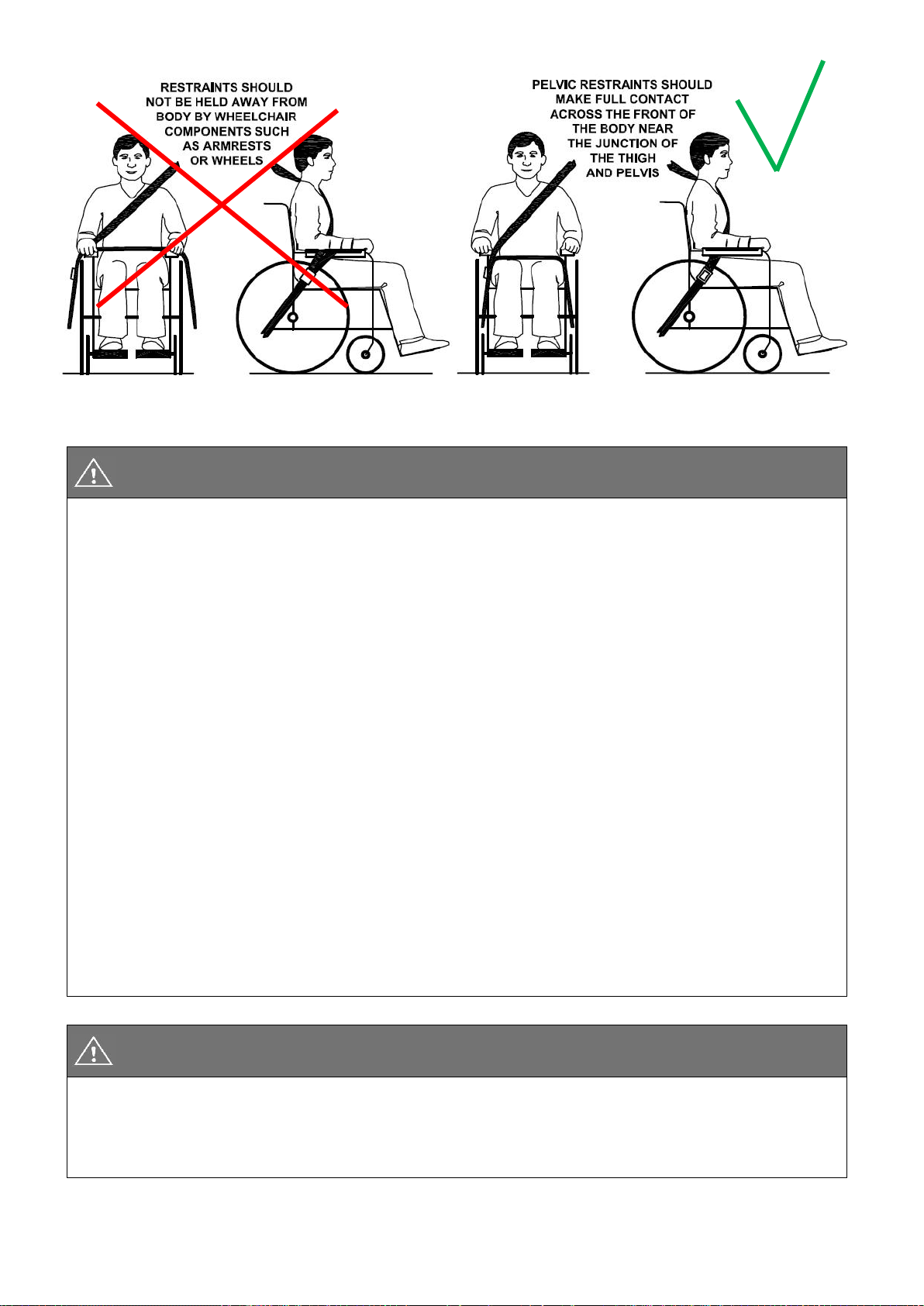
79
picture of improper belt fit picture of proper belt fit
NOTE
Please, make sure the following conditions are fulfilled to obtain a safe transportation:
- Whenever possible the occupied wheelchair shall be located in a forward-facing
configuration and secured by the tie downs in accordance with the WTORS (wheelchair tie
down and occupant-restraint system) manufacturer’s instructions.
- This wheelchair is suitable for use in vehicles and has met the performance requirements for
travelling forwards-facing in frontal impact conditions. Its use in other configurations within a
vehicle has not been tested.
- The wheelchair has been dynamically tested in a forward-facing orientation with the ATD
(anthropomorphic test device) restrained by both pelvic and upper torso belts.
- Both pelvic and upper torso belts should be used to reduce the possibility of head and chest
impacts with vehicle components.
- When possible, other auxiliary wheelchair equipment should be either secured to the
wheelchair or removed from the wheelchair and secured in the vehicle during transit, so that it
does not break free and cause injury to vehicle occupants in the event of a collision.
- Positioning supports should not be relied on for occupant restraint in a moving vehicle unless
they are labeled as being in accordance with the requirements specified in ISO 7176/19-2008.
- The wheelchair should be inspected by a manufacturer’s representative before reuse
following involvement in any type of vehicle impact.
NOTE
- Alterations or substitutions should not be made to the wheelchair securement points or to
structural and frame parts or components without consulting the manufacturer.
- Only use "gelled electrolyte" batteries on powered wheelchairs when used in a car.

80
17.4. transportation on an airplane.
When transporting your wheelchair by air, you should primarily pay attention to
the following items:
Gel batteries:
In most cases, they do not need to be removed from the wheelchair. The batteries only need to be
disconnected from the wheelchair.
To do this simply disconnect on of the battery pole connectors.
position of the front batterie position of the rear battery (behind both covers)
Acid batteries:
Most airlines require that batteries be removed from the wheelchair and transported in special boxes that
the airline may provide.
When transported by air, the wheelchair will be put with other goods in a confined space. Therefore, it is
important to take preventive action to minimize
transport damage to the wheelchair. Cover the control panel with soft, shock-absorbing material (foam
plastic or similar) and fold it in towards the back rest. Protect other protruding objects in a similar manner.
Tape any loose cables to the seat or covers.
wheelchair’s dimensions and weight:
How much the wheelchair weighs and how large it is are important, depending
on the type of airplane in which the wheelchair is to be transported. The smaller the airplane is, the smaller
the wheelchair may be/weigh and vice versa. Always check with the airline what rules apply.

81
17.5. transportation using Dahl docking station.
Morgan has also been crash tested using a Dahl docking station tie down system according to 7176-19:2008
and 10542-1:2012 SWM, where the wheelchair is facing forward in driving direction (driving direction like
the driver seat).
Morgan crash test using Dahl Docking station.
The locking of the wheelchair into the Dahl Docking station make it much easier to lock down the
wheelchair for occupied transportation. It can be used also for wheelchair users who want to drive the car
by themselves.
The system is self-locking and can be release by pushing a button. The locking device will open for a certain
time to make the un docking possible.
WARNING
The Dahl Docking station is only allowed to build in to a vehicle by trained and authorized staff
of a registered car adaptation company. For ordering the Dahl Docking and its accessories,
please contact Dahl Engineering in Denmark for further details. You can find Dahl at
www.dahlengineering.dk

82
17.6. mounting of the Dahl locking adapter on the wheelchair.
The Morgan chassis can be equipped with a Dahl docking plate underneath the battery box frame of the
chassis.
Morgan chassis with Dahl Docking plate mounted.
For detailed information about the Dahl Docking system, please visit the homepage:
www.dahlengineering.dk
To fit the Dahl docking plate, Karma Medical has created a special kit for Morgan chassis which included the
special part required for mounting the Dahl docking plate inside the battery box of Morgan. This kit is
available at an authorized supplier under Karma part no: 151200000023
Karma Art.no: 151200000332 Morgan Dahl mounting kit
WARNING
The Dahl Docking station is only allowed to build in to a vehicle by trained and authorized staff
of a registered car adaptation company. For ordering the Dahl Docking and its accessories,
please contact Dahl Engineering in Denmark for further details. You can find Dahl at
www.dahlengineering.dk

83
The Morgan chassis has dedicated holes in the chassis where the Dahl Docking plate can be mounted on.
dedicated holes for mounting Dahl mounting plate
1. Tilt the Morgan Chassis and check the holes for the mounting plates.
2. Mount the Dahl adapter plate in to the chassis using the 7 bolts and nuts which comes with the
mounting set. Tighten the bolts firmly
3. Now take the Dahl spacer (Dahl part no: 500673, docking plate (Dahl part no: 500561 and 5 special Dahl
high grade steel (14.9) Torx bolts (Dahl part no: 502800) to mount the Dahl docking plate on to the Morgan
chassis.
WARNING
The special Dahl high grade Torx bolts (Dahl part no: 502800) only come in one length which
often is too long. They need to be cut into the right light by the authorized engineer to fit the
locking plate properly without damaging the batteries.
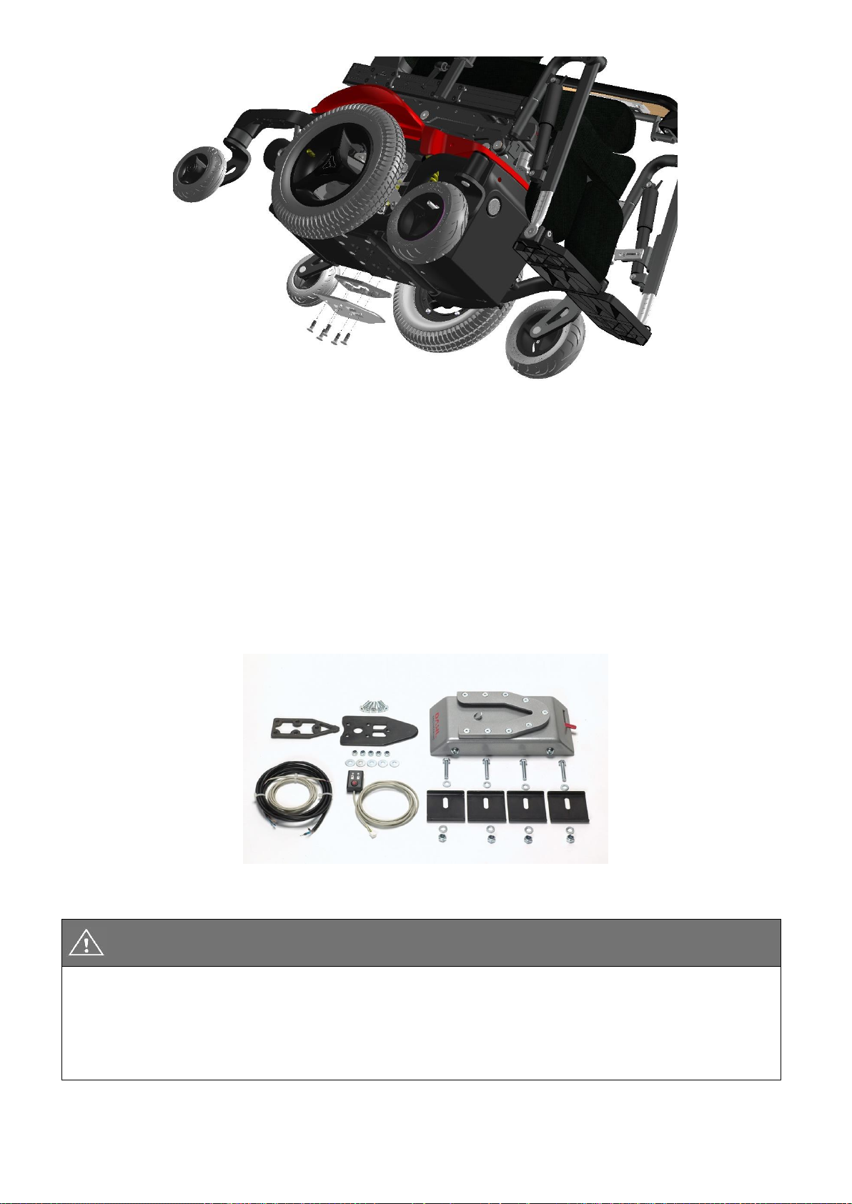
84
mounting the Dahl docking plate on to the Morgan chassis
4. After cutting the bolts to the right length, Loctite 222 needs to be added on to the thread to secure the
bolts.
5. the five Torx bolts shall be tightened with a torque wrench to the preset torque of 16-18 Nm.
6. place the batteries back into the chassis and connect them to the electronics.
Now the Morgan chassis is ready to be docked into the Dahl Docking station.
The mounting of the Dahl docking station into your vehicle shall only be executed by an authorized car
adaptation company. They will get the right support and information from Dahl Engineering how to mount
the docking station in to the designated vehicle.
Dahl docking kit
WARNING
The Dahl Docking station is only allowed to build in to a vehicle by trained and authorized staff
of a registered car adaptation company. For ordering the Dahl Docking and its accessories,
please contact Dahl Engineering in Denmark for further details. You can find Dahl at
www.dahlengineering.dk

85
Dahl Docking station
Dahl docking station mounted on the floor
Docking station and docking plate on chassis

86
17.7. locking procedure:
First, make sure the leg rests are not colliding with the ramp or the docking station when entering the
vehicle. Now drive the wheelchair slowly into the vehicle and make sure you center your wheelchair in the
middle of the docking module. If well positioned the locking system will also guide the wheelchair into the
docking station. keep in slowly driving until you feel the wheelchair is hitting the end position in the
docking station. At the same time, you will hear a clicking sound. The wheelchair is now locked in to the
docking station. the light on the control panel will light up de LED showing the wheelchair is locked in
correctly. Now switch the wheelchair off.
WARNING
If the wheelchair is not centered correctly, it might not be possible to lock in top the docking
station. In that case, retry by driving a bit backwards and re-center the wheelchair. try once
more until you hear the clicking sound and you see the locked sign LED on.
After the wheelchair is locked in, put the car safety belt on according to the instruction in chapters “safety
belt”.
WARNING
Do not forget to put the car safety belts on before driving in the vehicle. This on order to avoid
dangerous situations and personal- or wheelchair damage.

87
17.8. unlocking procedure
To unlock the wheelchair, first open up the car safety belt. Then switch on the wheelchair and switch to
drive mode. Push the joystick a little forward so the wheelchair is pushing itself a little to the forward
direction, releasing any pressure from the locking pin the Docking station. Now push the release button of
the Dahl Docking station. You will hear a firm click. The locking bolt is now retracted, and the wheelchair
can drive in reverse direction out of the Docking station.
NOTE
After pushing the release button of the Dahl Docking station, the locking bolt is retracted for a
certain period of time. After that time, the bolt will lift up again and lock the Docking station.
Make sure you drive your wheelchair out of the Docking station in this time window of the
unlocked position. If not, you have to push the release button one more time.
17.9. Manually unlocking in case of electric failure or accident:
The Dahl Docking station can be unlocked manually in case of an emergency or if the electric unlocking is
failing.
To unlock the docking station manually, the red lever needs to pull to the right. This retracts the locking bolt
manually so the wheelchair can be released out of the docking station.
WARNING
In case of a failure of the docking station, contact your local car adaptation company who has
build in the device into your vehicle. Only authorized and trained staff is allowed to work on the
docking device.

88
17.10. safety belt
positioning of the car safety belts for wheelchair users.
The wheelchair has been crash tested using a Dahl 3-point occupant safety belt, model 500984. We advise
you to use a similar system or a system that is equally specified. It is very important to use the safety belt in
the right angles according to the wheelchair user. The angle for the pelvis part (2) of the safety belt must be
in angle of 30- 75 ° with the horizontal plane. (see picture below). Also, the side angle should stay between
the vertical plane to maximum of 15° angle with the vertical plane. (see picture below).
optimal angles for a safety belt used by the wheelchair user

89
The shoulder part (1) of the safety belt should be positioned according to the figure below.
shoulder safety belt positioning
NOTE
Please obtain the following points for an optimal personal safety of the wheelchair user:
- the pelvic belt should be worn low across the front of the pelvis, so that the angle of the pelvic
belt is within the preferred zone of 30° to 75° to the horizontal, as shown in figure above.
- a steeper (greater) angle within the preferred zone is desirable.
- belt restraints should not be held away from the body by wheelchair components or parts,
such as the wheelchair armrests or wheels, along with an illustration similar to that of the
figure shown above.
- upper torso belts should fit over the shoulder and across the chest, as illustrated in figure of
the shoulder safety belt positioning.
- belt restraints should be adjusted as tightly as possible, consistent with user comfort.
- belt webbing should not be twisted when in use.

90
NOTE
Please, make sure the following conditions are fulfilled to obtain a safe transportation:
- Whenever possible the occupied wheelchair shall be located in a forward-facing configuration
and secured by the tie downs in accordance with the WTORS (wheelchair tie down and
occupant-restraint system) manufacturer’s instructions.
- This wheelchair is suitable for use in vehicles and has met the performance requirements for
travelling forwards-facing in frontal impact conditions. Its use in other configurations within a
vehicle has not been tested.
- The wheelchair has been dynamically tested in a forward-facing orientation with the ATD
(anthropomorphic test device) restrained by both pelvic and upper torso belts.
- Both pelvic and upper torso belts should be used to reduce the possibility of head and chest
impacts with vehicle components.
- When possible, other auxiliary wheelchair equipment should be either secured to the
wheelchair or removed from the wheelchair and secured in the vehicle during transit, so that it
does not break free and cause injury to vehicle occupants in the event of a collision.
- Positioning supports should not be relied on for occupant restraint in a moving vehicle unless
they are labeled as being in accordance with the requirements specified in ISO 7176/19-2008.
- The wheelchair should be inspected by a manufacturer’s representative before reuse following
involvement in any type of vehicle impact.
18. BATTERIES AND CHARGER
Except the joystick control panel can be operate by the occupant, other operations should be carried out by
an assistant.
Anything wheelchair related that requires tools should be done by your authorized Karma service provider.
18.1. Charging the Batteries
Before you attempt charging, ensure you read and understand the instruction manual supplied with the
battery charger, and you choose the correct input voltage for battery charger.

91
18.2. Charge the batteries if any of the following conditions occurs
- You have used your wheelchair for more than an hour continuously.
- You've used more than one quarter of the total charge.
- When you haven't used the wheelchair for more than two weeks.
- If the current charge is not enough to reach your final destination.
18.3. Be sure to precisely follow the procedures listed below.
Turn the wheelchair OFF.
Connect the charger's cord to a power outlet.
Then connect the charger's round plug(Figure 6-1) to the charging socket. (Figure 6-2)
The orange LED will light up as soon as the charging starts. The charging time is at least 8 hours, but it could
be as long as 12 hours, depending on the status of the batteries and the temperature.
The orange LED will change to green when the charging is completed.
Turn off the charger, disconnect the cord and pull out the round plug from the charging socket.
Figure 6-1
Figure 6-2
SUGGESTION
Do not disconnect the charger cord if the charging is not completed. The battery life will be
seriously shortened or decayed if the batteries are repeatedly used without being fully charged.
Therefore, be sure to always charge the batteries fully.
Always complete the charging when the LED light turns green. NEVER stop charging before it is
completed.
When finished charging, disconnect the charger plug from the charging socket as soon as possible.
Even when the charger is turned OFF, the electric power will slowly discharge if the cord is not
disconnected. DO NOT leave the charger ON connected to the wheelchair for more than 12 hours.
Charging time depends on the surrounding temperature; it takes longer in the winter.
CAUTION
Please follow the guidelines below to avoid accidents while charging.
Be sure to only use a KARMA approved battery charger and charge the battery completely every
time. The battery can be damaged if a non-genuine charger is used.
Never disassemble or modify the charger. This will void the warranty.
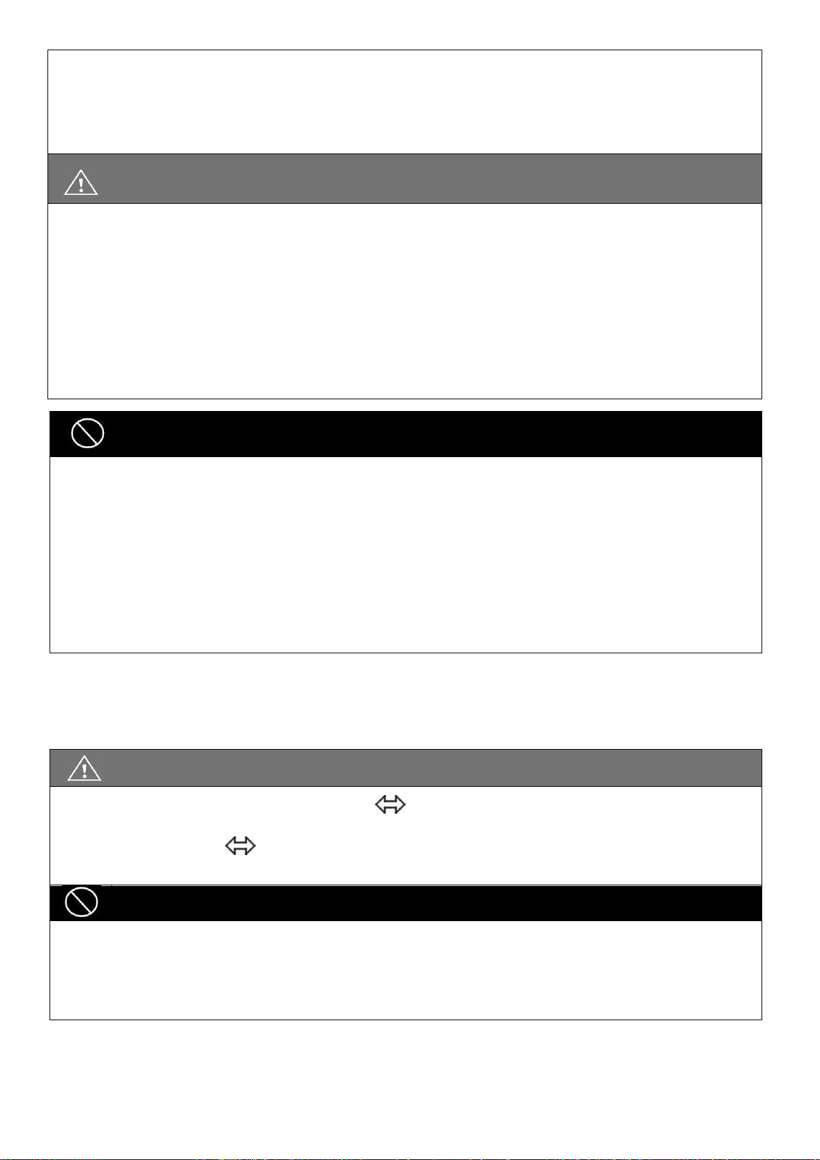
92
Please charge in a well-ventilated area where the battery is not directly exposed to sunlight. Do
not charge the battery under rainfall, in morning dew or in an area where the humidity is high.
Do not cover the wheelchair with any waterproof cloth or other objects while charging. Don't
charge in temperatures lower than -10℃(14°F) or higher than 50℃(122°F) as the charger may not
work well and the battery may become damaged.
CAUTION
The charger is not guaranteed to be water resistant.
Valve Regulated Lead-Acid batteries do not have a memory function like cell phone batteries
have. Please get in the habit of recharging your VRLA batteries frequently.
New batteries MUST be fully charged prior to initial use of the powered wheelchair.
Always charge new batteries before initial use or battery life will be reduced.
As a general rule, recharge batteries as frequently as possible to assure the longest possible life
and to minimize required charging time. Plan to recharge them when use of the powered
wheelchair is not anticipated
WARNING
Keep your wheelchair away from flammable objects while charging, as it may lead to fire or
explosion of the battery.
When the batteryies are charged, they may produce hydrogen. Therefore, do not smoke while
charging and charge in a well-ventilated area.
Never connect or disconnect the plug (cord) with wet hands or if the plug (cord) is wet to avoid
possible electric shock.
Never attempt to recharge the batteries by attaching cables directly to the battery terminals or
clamps. DO NOT jump start your wheelchair!
Do NOT attempt to recharge the batteries while the powered wheelchair is in operation.
18.4. Charger
The battery charger supplied by Karma is for indoor use only, it must be protected from moisture and
external heat source.
CAUTION
Before charging, make sure to set the 115V 230V switch to match the local AC voltage. If the
switch is improperly set to a lower or higher voltage position, it will cause damage to the charger,
and, change the 115V 230V switch settings only when charger is disconnected from AC line
voltage.
WARNING
The fan inside the charger will start to work when you turn on the charger. (for 8A charger will
start to work as the temperature reaches higher than 50℃ and stop running when the
temperature is lower than 50℃) If you find that the fan does not function properly, DO NOT use
the charger. Otherwise, the charger may overheat and start a fire.

93
18.5. Batteries
Do not expose the batteries to temperatures below -10℃(14°F) or above 50℃(122°F) when charging or
storing the vehicle.
Exceeding the specified temperature range can lead to either freezing or overheating of the batteries. This
will damage the batteries and shorten their lives.
The batteries used on your wheelchair are maintenance free sealed lead acid batteries. Thus, it is not
necessary to change or refill the battery liquid.
WARNING
Do not open the battery seal cap at any time.
After ANY adjustments, repair or service and BEFORE use, make sure that all hardware is
tightened securely. Otherwise, injury or damage may occur.
When removing/installing batteries, keep all foreign objects, especially metal, away from battery
terminals.
When the batteries fail to function, for environmental and safety concerns, please contact any
local recycle unit or KARMA supplier/dealer to handle them.
CAUTION
Place the powered wheelchair in a well-ventilated area where work can be performed without
risking damage to carpeting or floor covering.
Failure to use the correct battery size and/or voltage may cause damage to the powered
wheelchair and give unsatisfactory performance. For replacement of batteries, please contact
your local KARMA supplier/dealer in order to ensure that the new batteries are correctly be used.
Wheelchair MODEL
QTY
VOLTS
AMP/HOURS
Morgan
2
12
50
WARNING
NEVER allow any of your tools and/or battery cables to contact BOTH terminal posts at the same
time. An electrical short may occur and injury or damage may occur.

94
CAUTION
When tightening the clamps, always use a box or crescent wrench. Pliers will round off (strip) the
nuts. NEVER wiggle the terminal when tightening, as the battery may be damaged.
SUGGESTION
Charge batteries daily. It is critical not to let them run low at any time.
Do not use the battery to charge telecom equipment or other items.
Battery capacity will vary with outside conditions; the maximum drive range will decrease in the
winter. If the vehicle is not going to be used for a long time, please remember to charge the
batteries at least once every two weeks.
Karma recommends that both batteries be replaced if one battery is defective.
18.6. Cleaning the batteries
If a battery is contaminated by dirty water, battery acid, dust or other soil, the battery will discharge quickly.
Therefore, please follow the following steps to clean the battery:
- Turn the power OFF
- Use a clean cloth to wipe off the soiled part of the wheelchair around the battery.
- Clean the terminals and inside of the battery clamps by using a battery cleaning tool, wire brush or
medium grade sandpaper. Upon completion, these areas should be shiny, not dull.
- Examine the battery clamps/terminals for corrosion, if the terminal is covered by white powder, please
stop using the battery due to it indicates that there's possible leakage of the battery. Please replace the
batteries.
- Carefully dust off all metal particles.

95
19. INSPECTION AND MAINTENANCE
19.1. Daily check
Check the following items before driving. If you find anything abnormal, visit your KARMA wheelchair
dealer for further inspection before using it:
CAUTION
Except the joystick control panel can be operate by the occupant, other operations should be
carried out by an assistant. Anything wheelchair related that requires tools should be done by
your authorized Karma service provider.
Visit or contact a KARMA dealer for inspection and maintenance if you find anything abnormal.
Item
Inspection Content
Joystick
Controller
Is the joystick loose and/or making noise?
Can the joystick be turned left and right smoothly?
Can the speed buttons be adjusted freely and do
they function well?
Does the wheelchair stop when the joystick is
released completely?
Does it light up when the power is ON?
Is there enough power for your trip?
Does the horn work well?
Motor
Is there any abnormal noise?
Does the electromagnetic brake work properly?
Freewheel Mode
Do the freewheel levers work properly?
Driver's Seat
Does the driver's seat recline? (if applicable)
Do the seat angle adjustment knobs(or buttons)
work properly?
Does the surface of the seat remain or break?
Tires
Are there any cracks or other damage to the tires?
Check the tire tread depth and air pressure.
Other
Is there any abnormal motor noise?

96
19.2 Regular maintenance record
To make sure your wheelchair is in good condition, visit your KARMA wheelchair dealer regularly for
maintenance(and keep records accordingly ) every six months after purchasing. A maintenance/service fee
may apply.
SUGGESTION
Even if you don't use the wheelchair for a long time, the wheelchair should still be maintained
regularly.
You should clean your wheelchair, inside and out, regularly to keep it beautiful and safe.
I - Inspection A - Adjustment Δ - Repair 3 - Replacement T - Tightening L - Add Oil
Item/Period
1 mth
6 mth
12 mth
18 mth
24 mth
30 mth
Moving Parts (Refer to Section 7.7)
L Joystick Control Unit
I I I I/3
I/3
Power Module
I I I I/3
I/3
Controller Buttons
I I I I/3
I/3
Connection to the Electrical System
I I
I/A
Motor
Operation and Noise
I I
I/A
I/A
I/3
Electromagnetic Brakes
I I I I/3
I/3
Connection to the Electrical System
I I
Battery
Loose or Corroded Terminals
I I
Connection to the Electrical System
I I Damage to the Electrical Cord/Cable
I I
Charger
Charging Function and LED Light
I I I
I/Δ
I/Δ
I/Δ
Socket, Plug and Cords
I I
Fan Functions Properly (if applicable)
I
I/Δ
Driver's
Seat
Recline Function(if applicable)
I/L I/L
Tires
Cracks/Surface Damage
I/3
I/3
I/3
I/3
I/3
I/3
Tread Depth
I I/3 I I/3 I Abnormal Wear Pattern
I/3 I/3
Wheel
Rim
Tightness of Bolts and Nuts
T T Wear or Deformation Around Tires
I/3 I/3

97
19.3. Replacing the Batteries
Karma strongly recommends that bettery replacement and installation always be done by a qualified
technician. To replace the batteries, please refer to the photo below of the batteries equipped on the
Morgan series, and follow the below instructions to remove and load the batteries. The weight of one
battery could be more than 10 kg. Please handle it with care.
WARNING
Do turn off the power of the wheelchair before replacing or loading the batteries.
Do NOT allow conductive material such as a wrench to contact BOTH battery terminals at the
same time. This will result in a short that can cause burns to you and damage the battery.
Most batteries are not sold with instructions. However, warnings are frequently noted on top
of the batteries. Read them carefully.
Do NOT allow the liquid in the battery to come in contact with skin, clothes or other items. It
is a form of acid and may cause harmful or damaging burns. Should the liquid come into
contact with skin, rinse the area immediately and thoroughly with cool water. If liquid comes
into contact with eyes, flush eyes immediately and seek medical attention as soon as possible.
The use of rubber gloves and chemical goggles are recommended when working with
batteries.
NEVER smoke or strike a match near the batteries.
Replace the batteries IMMEDIATELY if there are any cracks or leaks.
Remove the Batteries
Captain seat:
to remove the front battery:
Remove the Front Battery:
Remove the two screws on the battery casing in the front of the wheelchair. (Figure 6-3)
Remove the battery casing. (Figure 6-4)
Place the front casing aside and pull the cables out. (Figure 6-5)
Unfasten the battery strap. (Figure 6-6)
Disconnect both of the wire terminals of the battery. Cap the wire terminals to avoid any short circuit.
(Figure 6-7)
Hold the front battery and slightly pull it out. (Figure 6-8 & 6-9)
Place the front battery on the ground. Put aside the wires detached from the front battery and keep them
away from touching the terminals of the batteries. (Figure 6-10)
Figure 6-3
Figure6-4
Figure6-5
Figure6-6

98
Figure6-7
Figure6-8
Figure6-9
Figure6-10
Figure 6-11
Figure 6-12
Figure 6-13
Figure 6-14
Figure 6-15
Figure 6-16
Remove the Rear Battery
Remove the two screws on the battery casing in the back of the wheelchair. (Figure 6-11)
Remove the rear battery casing (Figure 6-12)
Place the back casing aside and pull the cables out. (Figure 6-13)
Loosen the battery strap. (Figure 6-14)
Disconnect both wire terminals of the battery. Cap the wire terminals to avoid any short circuit.
(Figure 6-15)
Hold the rear battery and slightly pull it out.
Place the rear battery on the ground. Put aside the wires detached from the front battery and keep
them away from touching the terminals of the batteries. (Figure 6-16)
Load the Batteries
Load the batteries by reversing the procedures of Section 6.7.1 Remove the Batteries.
Load the Rear Battery:
Load the rear battery back into the battery box.(Figure 6-15). Connect the red wire (marked with [A])
with the positive terminal (the RED end). Connect the black wire (also marked with [A]) with the
negative terminal (the BLACK end). Make sure the terminals are properly connected.
Adjust the strap first to so that the remaining end of the strap is not protruding out of the battery box.
(Figure 6-14)
Fixate the wires and the battery by pulling firmly on the battery strap. Fasten the strap firmly.
(Figure 6-14)
Re-tighten the screws on the rear cover. (Figure 6-11 & 6-12)
Load the front battery:

99
Load the battery back into the battery box. (Figure 6-8). Connect the red wire (marked with [A] ) with the
positive terminal (the red end). Connect the black wire (also marked with [A]) with the negative terminal
(the black end). Make sure the terminals are properly connected.
Adjust the strap first to so that the remaining end of the strap is not protruding out of the battery box.
(Figure 6-6)
Fixate the wires and the battery by pulling firmly on the battery strap. Fasten the strap firmly. (Figure 6-6)
Re-tighten the screws on the rear cover. (Figure 6-3 & 6-4)
Sling Seat:
Remove the actuator and the front battery:
Use two 17mm open end wrenches to remove the screws for fixing the upper end of the actuator.
(Figure 6-17)
Remove the screws for fixing the lower end of the actuator. (Figure 6-18)
Remove the actuator and put it aside. (Figure 6-19)
Use 5mm L-shape wrench to remove the four screws which are used to fasten the fixing plate for the
actuator. (Figure 16-21)
Repeat steps 6.7.1 and 6.7.2 for replace batteries.
Install the fixing plate and the actuator back the powered wheelchair.(Figure 6-21, Figure 6-22)
Make sure the actuator and the powered wheelchair can work properly
Figure 6-17
Figure-18
Figure 6-19
Figure-20
Figure-21
Figure 6-22

100
WARNING
There are many risks involved with improper disposal of batteries, whether damaged or not.
Batteries may contain heavy metals and be considered hazardous waste.
Many regions around the world now strictly enforce laws to help protect our environment. By not
disposing of batteries properly, you may be liable for fines from your local through national
government.
By not recycling batteries, they end up in landfills where lead and other chemicals may leach into
streams and rivers destroying ecosystems and poisoning local water resources.
Improper disposal of batteries may also cause injury to unsuspecting others that come in contact
with them. If you come in contact with fluids or corroded powder from a battery, rinse with water
and contact a physician if necessary. If contact with eyes occurs, rinse for 15 minutes and then visit a
physician.
DO NOT incinerate or burn the battery. It will cause it to explode!
Please see the end of chapter: Cleaning & Recycling for more information.
SUGGESTION
If necessary or if you have any question in the above procedures, ask for help from your local KARMA
wheelchair dealer for cleaning and replacing the batteries.
19.4. Tires
- The condition of the tires is affected by the way you drive and use your wheelchair.
- Inspecting Tire Tread: please check the tread depth regularly.
- Replace the tires when the tread depth is less than 0.5 mm.
- The tires could be pneumatic or PU tires. It depends on the specification of the wheelchair. If they are
pneumatic tires, please refer to the tires pressure specified on the tire walls to maintain the tires at the
correct pressure. Do not let anyone touch the wheels when the wheelchair is in motion to avoid pinch
injury.
CAUTION
When the tread depth is below 1 mm, the tire does not have good traction. This may lead to
vehicle slippage and makes braking distances much longer. Thus, go to your Karma dealer to
replace the tire as soon as possible if it has less than a 1 mm tread depth.
The tire pressure of all the front casters and the rear wheels must be kept at 35-40 PSI (approx.
2.46~2.81 kg/cm or 2.415~2.76 bar=241-276 kPa) for the best drive range (maximum distance
travelled per charge) and usage/ handling. Please refer to the tire pressure specified on the tire
walls to maintain the tires at the correct pressure.
Since the wheelchair is rather heavy, it is recommended to let your authorized supplier repair eventual tire
punctures. First lift the wheelchair so that the punctured tire is free from the ground. Both front and rear
wheel tires can be taken off by loosening the 3 bolts (B) which hold the wheels on to the wheelchair.
 Loading...