

Karma KM-8522 Series, KM-8022 Series Maintenance Manual

Manual Wheelchair Maintenance Manual
KM-8022/KM-8522 series

Introduction
This manual contains basic detail information about the Removal / Replacement for Karma
KM-8022/KM-8522 series to enable Karma’s authorized dealers to provide better after
service. It is not intended to be a comprehensive maintenance guide or provide detail
assembly/disassembly of the products. The parts and names may be different from
countries to countries due to the area difference and customers’ spec selection. The step,
therefore, may be not the same. If you need to inquire more detail information, please
contact Karma. Karma reserves the rights to modify the contents without prior notification.
1. This wheelchair is designed and manufactured by:
Karma Medical Products Co., Ltd.
No.2363 Sec.2, University Rd., Min-Hsiung Shiang, Chia-Yi 621, Taiwan
Tel:+886-5-2066688
Fax:+886-5-2067788
Web: www.karmamedical.com
E-Mail: globalsales@karma.com.tw
Authorized representative in the European Union
Karma Mobility Ltd.
Unit 6 Target Park, Shawbank Road, Redditch, B98 8YN U.K.
Tel: 0845 630-3436
Fax: 0845 630 3736
Web: www.karmamobility.co.uk
E-Mail: info@karmamobility.co.uk
2. For after service, including repairs, service and spare parts demand, please contact the
dealer shop where you purchased the products.
3. Please quote the following information at all times:
Part section and Part Number
Part Name/Description
Quantity required
4. Warranty Policy- Do use the parts Karma provides to meet the requirement of
product quality and warranty policy. For more detail, please
refer to user manual / distribution contract
5. Technical Data
5.1 Seat Width/ Depth Options: Refer to user manual.
5.2 Wheels Options (Caster X Rear Wheels): Refer to section 3.1 and 3.2.

5.3 Limited Loading Weight: 130KG
6. Accessories
Footrest: Amputee support / 90 degree footrest/ Footrest extension kit
Footplate: Angle adjustable footplate / Aluminum footplate
Others: Multi-function safety / Backrest bag / Lateral backrest support bar / Tension
adjustable backrest upholstery / Tension adjustable seat upholstery / Net
sack /1”,2”Seat depth extension tube”(should adapt Footrest
extension kit ) / IV Pole/ Oxygen tank holder/

TABLE OF CONTENTS
1. Instructions of Replacement --------------------------------------------------------------------- 1
1.1 Backrest --------------------------------------------------------------------------------------- 1
1.2 Armrest --------------------------------------------------------------------------------------- 2
1.3 Footrest --------------------------------------------------------------------------------------- 5
1.4 Brake ------------------------------------------------------------------------------------------ 8
1.5 Frame ---------------------------------------------------------------------------------------- 10
1.6 Wheels --------------------------------------------------------------------------------------- 11
1.7 Rear Wheel Assembly ----------------------------------------------------------------------- 12
1.8 Casters --------------------------------------------------------------------------------------- 13
2. Instructions of Replacement for Optional Devices --------------------------------------------- 14
2.1 Anti-Tipper ---------------------------------------------------------------------------------- 14
2.2 Tie Down Hook ------------------------------------------------------------------------------ 15
2.3 Oxygen Tank Holder ------------------------------------------------------------------------- 16
2.4 IV Pole Assembly ---------------------------------------------------------------------------- 17
2.5 Walking Stick Box Assembly ----------------------------------------------------------------- 18
2.6 Lateral Support Assembly ------------------------------------------------------------------- 19
2.7 Hemi Armrest Assembly --------------------------------------------------------------------- 20
2.8 Elevating & Swing Away Footrest ----------------------------------------------------------- 22
2.9 Stump Footrest ------------------------------------------------------------------------------ 24
2.10 Vertical Swing-Away Footrest -------------------------------------------------------------- 26
2.11 Angle and Depth Adjustable Footrest ----------------------------------------------------- 28
2.12 Drum Brake --------------------------------------------------------------------------------- 29
2.13 Adjustable Backrest Tube ------------------------------------------------------------------ 30
3. Instructions of Adjustment ---------------------------------------------------------------------- 31
3.1 Adjusting Seat Height for Wheelchair Equipped with 20, 22 or 24 Inch Rear Wheels ------ 31
3.2 Seat Height Adjustment for Wheelchair Equipped with 14 inch Rear Wheels ------------- 34
3.3 Caster Adjustment for wheelchair Equipped with 20, 22 or 24 Inch Rear Wheels ---------- 35
3.4 Caster Adjustment for Wheelchair Equipped with 14 inch Rear Wheels ------------------- 38
1
1. Instructions of Replacement
1.1 Backrest
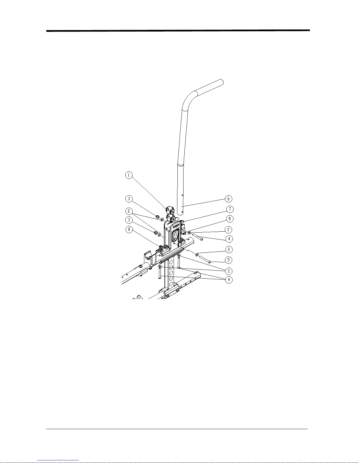
1.1.1 Backrest Frame
Figure 1.1.1
1. Backrest Tube Sleeve
2. M6 Flat Washer
3. Hex Nylon Dome Nut
4. Button Head Cap Screw M6*45L
5. Button Head Cap Screw M6*50L
6. Backrest Push Handle Tube-Lengthened
7. Backrest Tube Base KM-8022
8. Hex Nylon Nut
Tools:
-4 mm L-shape Allen Key
- 10 mm open end wrench
2
Removal and Replacement:
1.1.1.1Use 4 mm L-shape Allen Key and 10 mm open end wrench to loosen part 4 and 5.
1.1.1.2 Remove part 6.
1.1.1.3Re-assembly is done in reverse order.
Key Inspection:
● Make sure all screws are properly tightened.
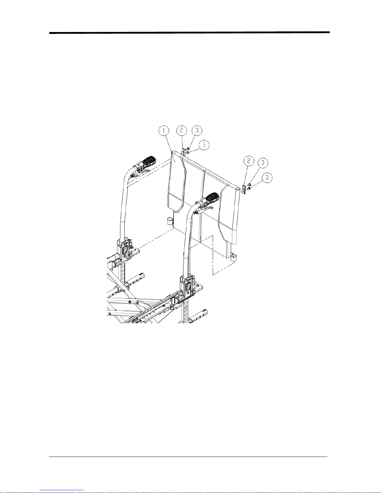
1.1.2 Backrest Upholstery
Figure 1.1.2
1. Backrest Upholstery
2. Backrest Upholstery Two Holed Arc Washer
3. Button Head Phillips Tap Screw
Tools:
- Philips screwdriver
Removal and Replacement:
1.1.2.1 Use a Philips screwdriver to loosen part 3.
1.1.2.2 Remove part 2 and part 1.
1.1.2.3 Re-assembly is done in reverse order.
Key Inspection:
● Make sure all screws are properly tightened.
2
1.2 Armrest
1.2.1 Flip-Back Armrest
Figure 1.2.1
1. Flip-back Elevating Armrest Assembly
2. M8 Socket Head Cap Screw
3. 7/8" Plastic Arc Washer
4. Armrest Clamp Bushing
5. M8 Flat Washer
6. M8 Spring Washer
7. M8 Hex Nylon Dome Nut
Tools:
- 13 mm open end wrench X 2
Removal and Replacement:
1.2.1.1 Use two 13 mm open end wrenches to loosen part 2 and part 7.
1.2.1.2 Replace part 1.
1.2.1.3 Re-assembly is done in reverse order.
Key Inspection:
● Make sure all screws are properly tightened.

3
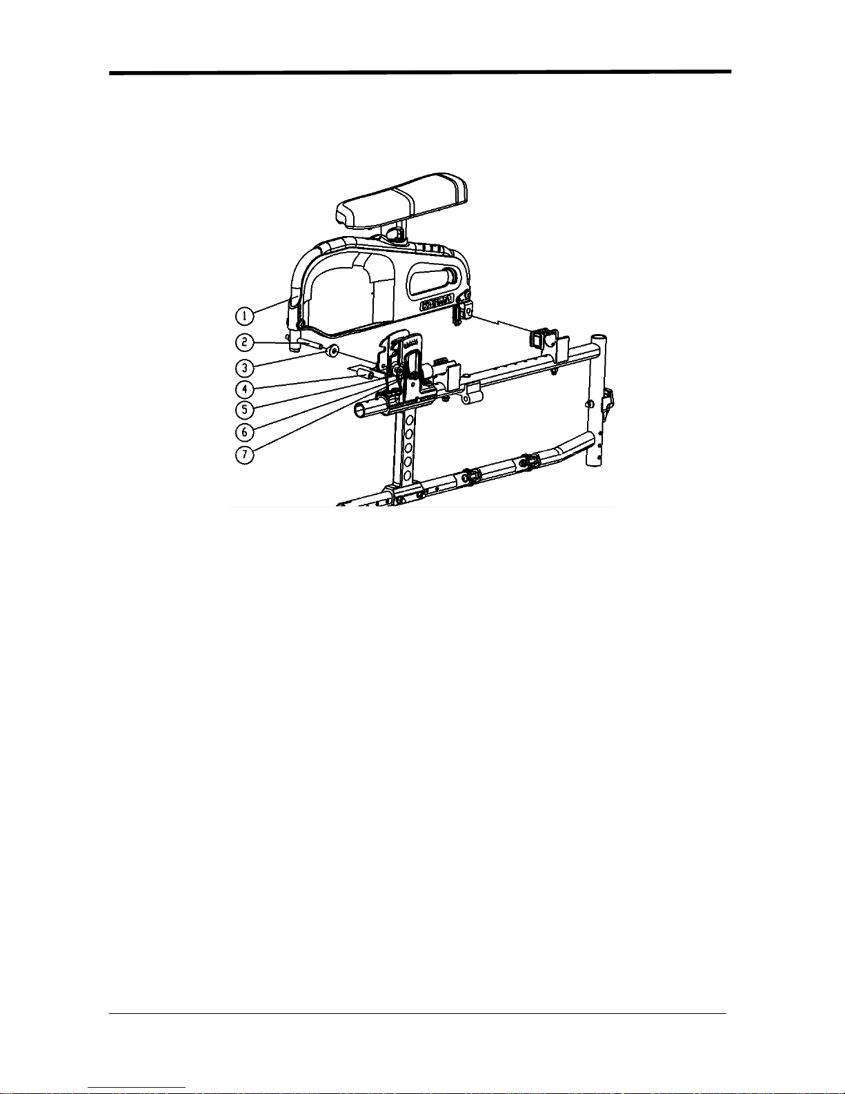
1.2.2 Side Panel Assembly
Figure 1.2.2
1. Screw Binding Post Set
2. M6 Plastic Washer
3. Side Panel Positioning Part
4. Side Panel Lock
5. Spring Pin
6. Truss Phillips Tapping Screw
7. Armrest Elevating Bracket
Tools:
- 4 mm L-shape Allen Key x2
- Philips Screwdriver
-Φ6 Rod
- Hammer
Removal and Replacement:
1.2.1.1 Use Philips screwdriver to loosen part 6 and remove part 7.
1.2.1.2 Use 4 mm L-shape Allen Key to loosen part 1 and remove part 3.
1.2.1.3 Use rod and hammer to remove part 5 and replace part 4.
1.2.1.4 Re-assembly is done in reverse order.
Key Inspection:
● Make sure all screws are properly tightened.
4
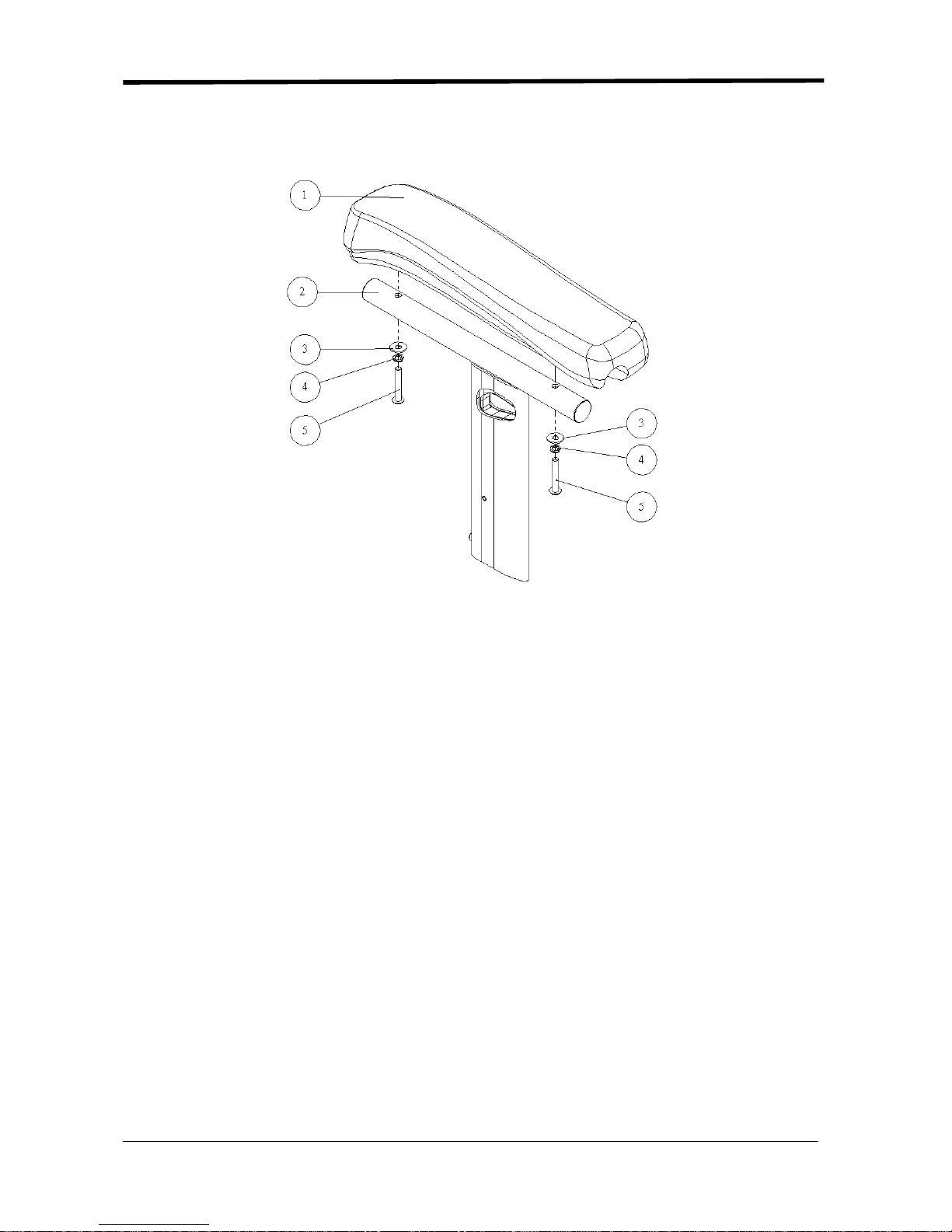
1.2.3 Height Adjustable Armrest Assem bly
Figure 1.2.3
1. Ergo Armrest
2. Gold Trigger Elevating Armrest
3. M5 Flat Washer
4. M5 Spring Washer
5. M5 Button Head Cap Screw
Tools:
- 3 mm L-shape Allen Key
Removal and Replacement:
1.2.3.1 Use 3 mm L-shape Allen Key to loosen part 5. Remove part 1 and part 2.
1.2.3.2 Re-assembly is done in reverse order.
Key Inspection:
● Make sure all screws are properly tightened.
5
1.3 Footrest
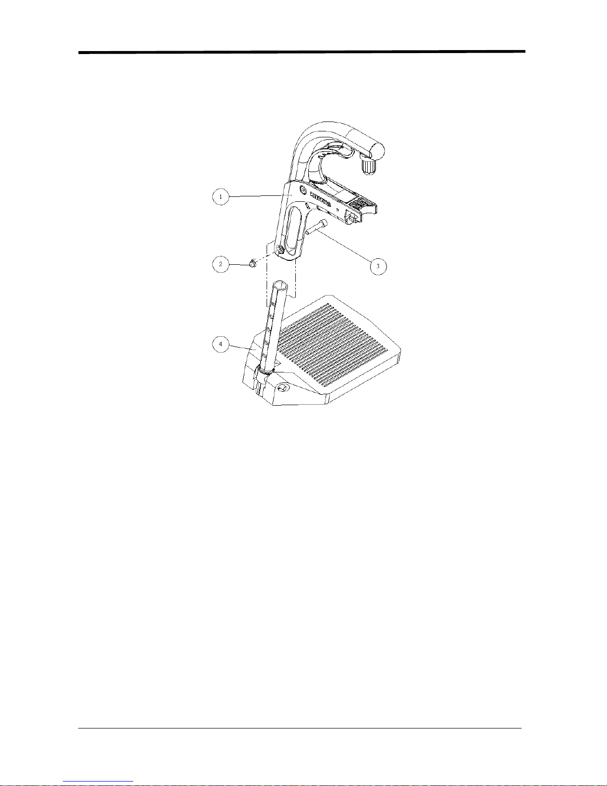
1.3.1 Footplate
Figure 1.3.1
1. Grip Footrest
2. M6 Hex Nylon Dome Nut
3. M6 Hex Socket Head Cap Screw
4. Footplate
Tools:
-4 mm L-shape Allen Key
- 10 mm open end wrench
Removal and Replacement:
1.3.1.1 Use 4 mm L-shape Allen Key and 10 mm open end wrench to loosen part 2 and part 3.
1.3.1.2 Remove part 4.
1.3.1.3 Re-assembly is done in reverse order.
Key Inspection:
● Make sure all screws are properly tightened.
6
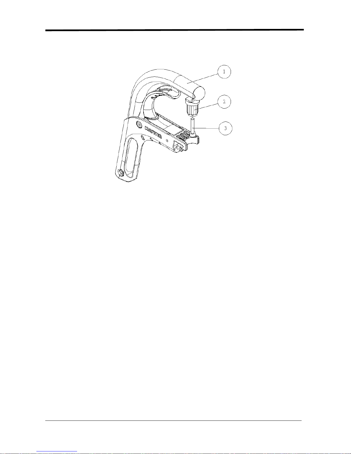
1.3.2 Grip Footrest
Figure 1.3.2
1. Grip Footrest
2. Y-shaped T ube Plug
3. M6 Hex Socket Head Cap Screw
Tools:
-4 mm L-shape Allen Key
Removal and Replacement:
1.3.2.1 Use 4 mm L-shape Allen Key to loosen part 2.
1.3.2.2 Remove part 3.
1.3.3.3 Re-assembly is done in reverse order.
Key Inspection:
● Make sure all screws are properly tightened.
7
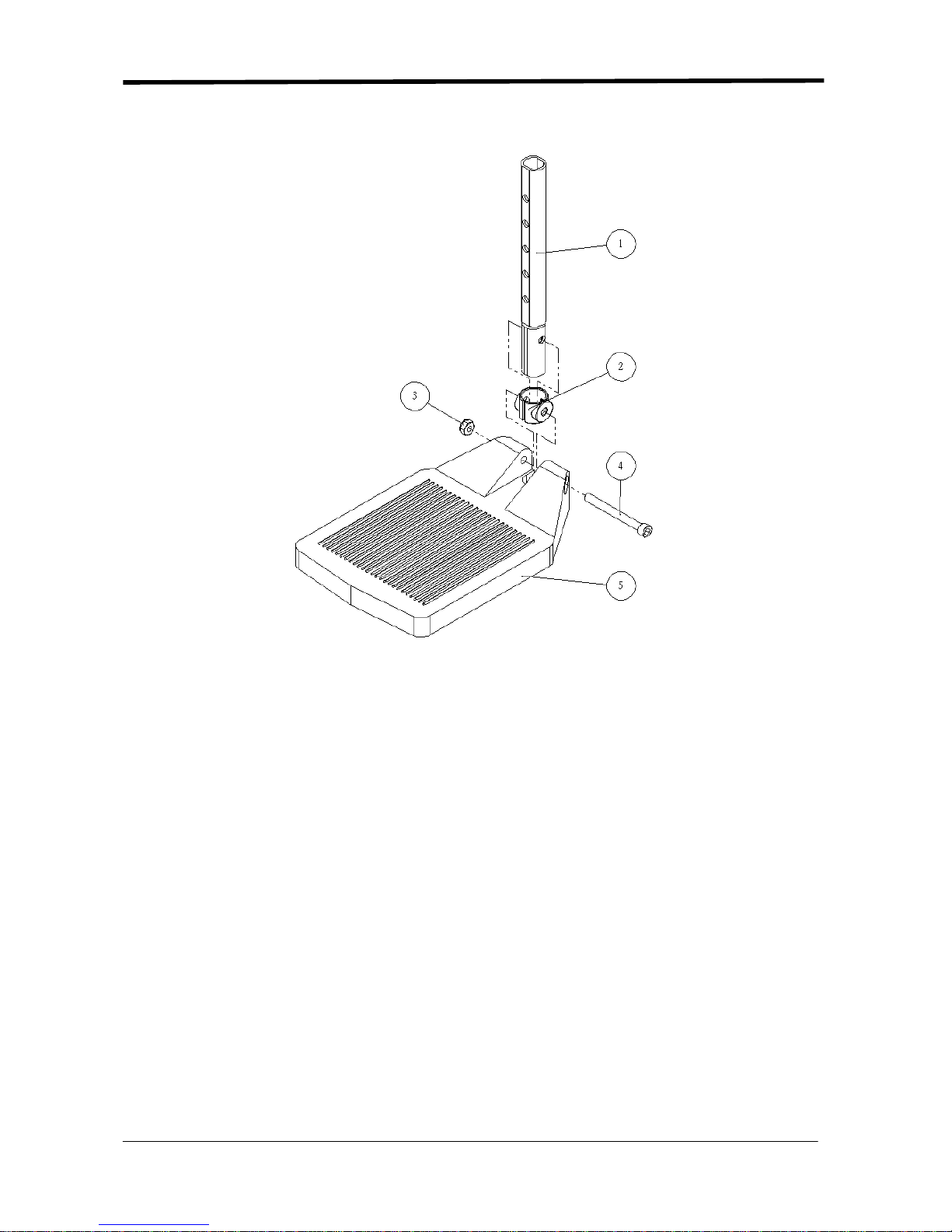
1.3.3 Footplate
Figure 1.3.3
1. Footplate Tube
2. Sleeve
3. 1/4" Nylon Lock
4. 1/4" Hex Socket Head Cap Screw
5. Footplate
Tools:
-5 mm L-shape Allen Key
Removal and Replacement:
1.3.2.1 Use 5 mm L-shape Allen Key to loosen part 3 and part 4.
1.3.2.2 Remove part 5.
1.3.3.3 Re-assembly is done in reverse order.
Key Inspection:
● Make sure all screws are properly tightened.
8
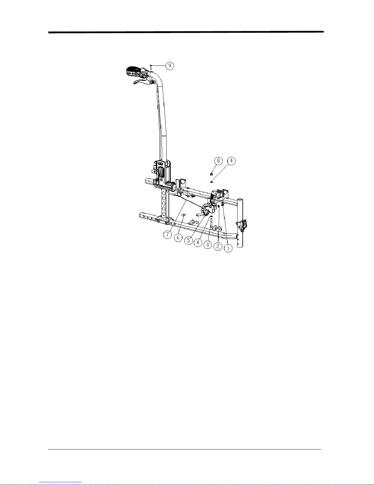
1.4 Brake
Figure 1.4
1. M6 Hex Nylon Dome Nut
2. M6 Spring Washer
3. M5 Button Head Cap Screw
4. M5 Flat Washer
5. Brake
6. Brake Cable Bolt
7. Brake Cable
8. M6 Hex Nylon Dome Nut
9. M5 Button Head Cap Screw
Tools:
-4 mm L-shape Allen Key
- 8 mm open end wrench
- 10 mm open end wrench

9
Removal and Replacement:
1.4.1 Use 8 mm open end wrench to loosen part 1.
1.4.2 Remove part 7.
1.4.3 Use 4 mm L-shape Allen Key and 10 mm open end wrench to loosen part 3 and part 8.
1.3.4 Remove part 5.
1.3.5 Re-assembly is done in reverse order.
Key Inspection:
● Make sure all screws are properly tightened.
 Loading...