

Page 1

GEBRAUCHSANWEISUNG
®
UP 210 ENDOMAT
SELECT
INSTRUCTION MANUAL
®
UP 210 ENDOMAT
SELECT
MANUAL DE INSTRUCCIONES
UP 210 ENDOMAT® SELECT
Page 2

Wichtiger Hinweis für die
Benutzer von KARLSTORZ
Geräten und Instrumenten
Important information
for users of KARLSTORZ
instruments
Indicaciones importantes
para los usuarios de equipos
e instrumentos KARLSTORZ
1. Wichtiger Hinweis für die
Benutzer von KARLSTORZ
Geräten und Instrumenten
Es wird empfohlen, vor der Verwendung die
Eignung der Produkte für den geplanten
Eingriff zu überprüfen.
Vielen Dank für Ihr Vertrauen in den Namen
KARL STORZ. Auch in diesem Produkt steckt
unsere ganze Erfahrung und Sorgfalt. Sie und
Ihr Haus haben sich damit für ein modernes
und hochwertiges Gerät der Firma
entschieden.
Die vorliegende Gebrauchsanweisung soll helfen,
den ENDOMAT
anzuschließen und zu bedienen. Alle notwendigen
Einzelheiten und Handgriffe werden an schaulich
erklärt. Bitte lesen Sie deshalb diese Anleitung
sorgfältig durch; bewahren Sie sie zum etwaigen
Nachlesen in der mitgelieferten Schutzhülle an gut
sichtbarer Stelle beim Gerät auf.
®
SELECT richtig aufzustellen,
KARL STORZ
1. Important information
for users of KARLSTORZ
instruments
It is recommended to check the suitability of
the product for the intended procedure prior
to use.
Thank you for your expression of confidence in
the KARL STORZ brand name. Like all of our
other products, this product is the result of years of
experience and great care in manu facture. You and
your organization have decided in favor of a modern,
high-quality item of equipment from KARL STORZ.
This instruction manual is intended to serve as an
aid in the proper setup, installation, and ope r a tion of
the ENDOMAT
equipment and all actions required on your part are
clearly presented and explained. We thus ask that
you read this manual carefully before proceeding
to work with the equipment. Insert this manual in
its protective wallet and keep it available for ready
reference in a convenient and conspicuous location
near the equipment.
®
SELECT. All essential details of the
1. Indicaciones importantes
para los usuarios de
equipos e instrumentos
KARLSTORZ
Antes de su utilización, se recomienda
comprobar la idoneidad de los productos en
cuanto a la intervención planeada.
Agradecemos la confianza que ha depositado
en la marca KARL STORZ. Este producto, como
todos los demás, es el resultado de nuestra amplia
experiencia y esmero. Con esta adquisición, tanto
usted como su institución se han decidido por
un producto
calidad y tecnología vanguardista.
El presente Manual de instrucciones contiene todas
las indicaciones necesarias para la instalación,
puesta en funcionamiento y manipulación de la
ENDOMAT
explicaciones necesarias sobre las particularidades
y los detalles de su manejo. Recomendamos la
lectura detenida de esta Instrucción y su colocación
cerca del aparato, en un lugar visible para facilitar
la consulta y debidamente protegido en la funda de
plástico que se adjunta.
KARL STORZ de gran precisión, alta
®
SELECT. Con tal fin, contiene todas las
CAUTION: Federal (USA) law restricts this device
Version 1.1 – 08/2017 96116049 D
II
to sale by or on the order of a physician.
Page 3
Images of the device Imágenes del equipoGeräteabbildungen
2. Geräteabbildungen 2. Images of the device
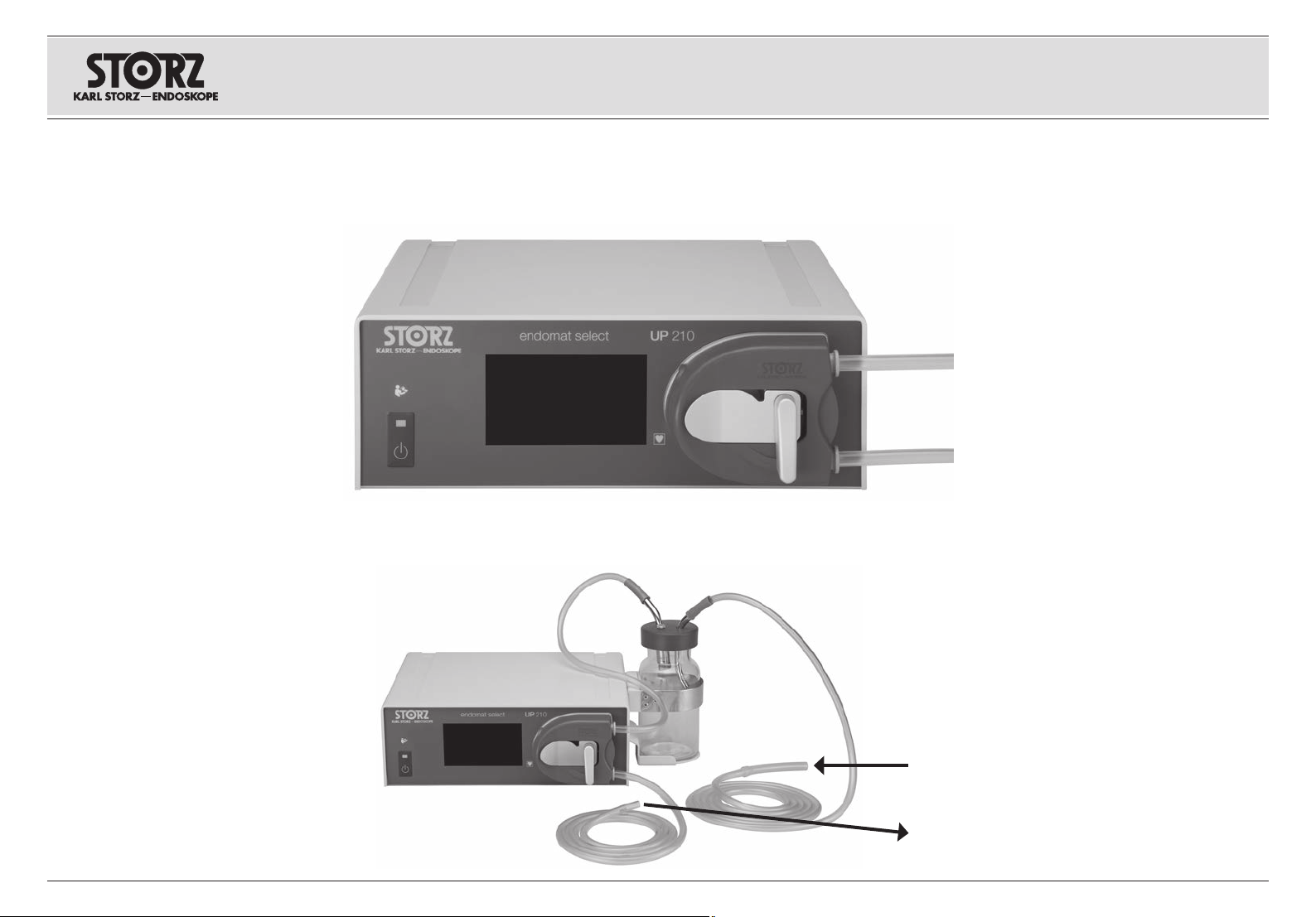
2. 1 Betrieb als Spülpumpe 2. 1 Operation as irrigation pump
2. 2 Betrieb als Saugpumpe 2. 2 Operation as suction pump
2. Imágenes del equipo
2. 1 Funcionamiento como bomba
de irrigación
➞
vom Spülflüssigkeitsbeutel
from the irrigation-liquid bag
de la bolsa de líquido de irrigación
zum Instrument
to the instrument
➞
al instrumento
2. 2 Funcionamiento como bomba
de succión
vom Instrument/Patient
from instrument/patient
del instrumento/paciente
zum Auffangbehälter
to the collecting container
al recipiente colector
III
Page 4
W ER
Images of the device Imágenes del equipoGeräteabbildungen
Q T YU I P
O {
}
IV
Page 5

Bedienungselemente,
Anzeigen, Anschlüsse
und ihre Funktion
Controls, displays,
connectors, and
their uses
Elementos de control,
indicadores, conexiones
y sus funciones
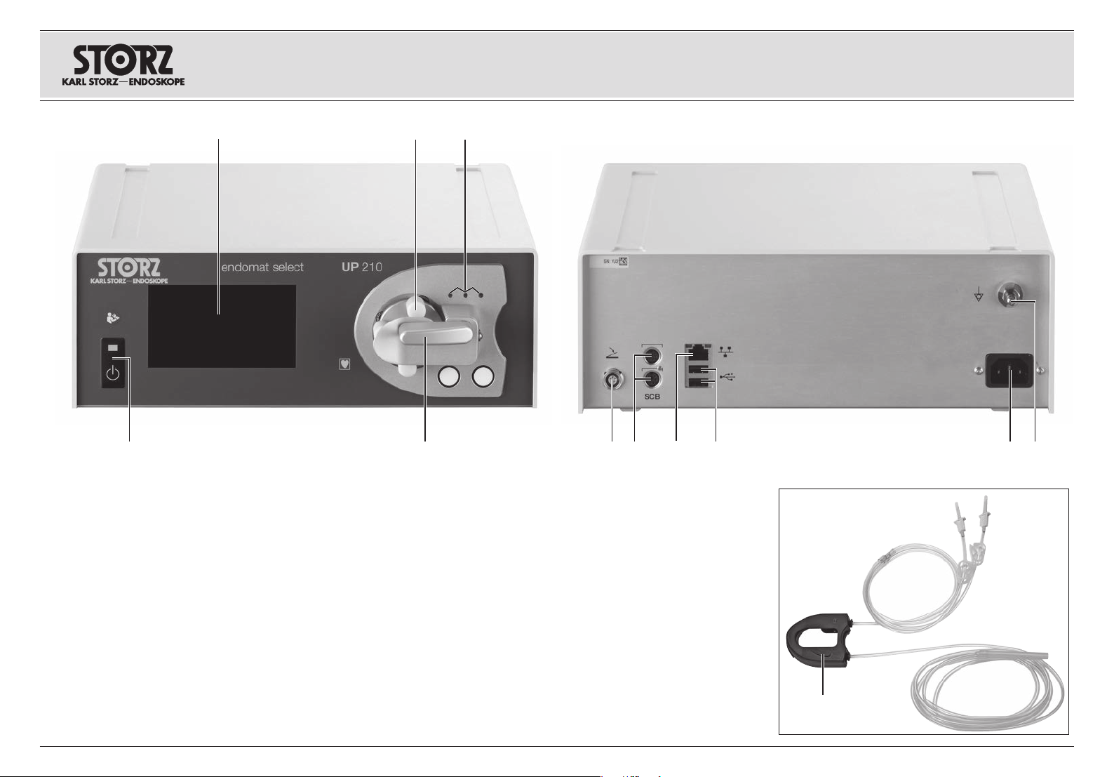
3. Bedienungselemente,
Anzeigen, Anschlüsse
undihre Funktion
1 Netzschalter
2 TFT Touch-Bildschirm
3 Pumpenrollen
4 Lichtschranke
5 Pumpenhebel (Verriegelungshebel Kassette)
6 Anschlussbuchse (beispielsweise) für
Fußschalter
7 SCB-Anschlüsse*
8 Service-Schnittstelle (Ethernet)**
9 Service-Schnittstelle (USB)**
0 Netzanschlussbuchse
q Potentialausgleichsanschluss
w Schlauchkassette für Einmalgebrauch
* Die KARL STORZ-SCB Schnittstelle
®
(KARL STORZ Communication Bus), die auf
dem CAN Feldbus basiert, ermöglicht eine
Fernsteuerung von Gerätefunktionen, sowie eine
Fernanzeige von Geräteparametern.
**WARNUNG: Der ENDOMAT® SELECT
ist nicht dafür vorgesehen mit anderen
3
Geräten über die USB- oder EthernetSchnittstelle verbunden zu werden.
Diese Schnittstellen sind nur dem
KARLSTORZ Service vorbehalten.
Eine Verbindung des ENDOMAT® SELECT
mit einem IT-Netzwerk, das weitere Geräte
enthält, kann bisher unbekannte Risiken für
Patienten, Bediener oder Dritte hervorrufen.
Da die Rahmenbedingung, Installation
und der Betrieb eines IT-Netzwerkes in
der Verantwortung des Betreibers liegen,
kann KARLSTORZ keine Garantie für
einen fehlerfreien Betrieb übernehmen. Der
Betreiber muss den Schutz, die Sicherheit
und Zuverlässigkeit des IT-Netzwerks durch
Risikomanagement gemäß IEC80001
sicherstellen.
3. Controls, displays,
connectors, and
their uses
1 Power switch
2 TFT touch screen
3 Pump rollers
4 Light barrier
5 Pump lever (cartridge locking lever)
6 Connection socket (example) for footswitch
7 SCB connectors*
8 Service interface (Ethernet)**
9 Service interface (USB)**
0 Power cord receptacle
q Potential equalization connector
w Disposable tubing cartridge
* The KARL STORZ-SCB interface (KARL STORZ
Communication Bus), based on the CAN field bus,
permits remote control of equipment functions, as
well as remote display of equipment parameters.
**WARNING: The ENDOMAT® SELECT
is not intended to be connected to other
3
equipment via the USB or Ethernet
interface. These interfaces are exclusively
reserved for KARL STORZ service.
Connecting the ENDOMAT® SELECT to an
IT network that includes other equipment
could result in previously unidentified risks
to patients, operators or third parties.
Since the framework condition, installation,
and operation of an IT network are the
responsibility of the operator, KARL STORZ
cannot guarantee failure-free operation.
The operator must ensure the protection,
safety, and reliability of the IT network
through risk management in accordance
with IEC 80001.
3. Elementos de control,
indicadores, conexiones
ysus funciones
1 Interruptor de red
2 Pantalla táctil TFT
3 Rodillos de la bomba
4 Barrera de luz
5 Palanca de bomba (palanca de enclavamiento
del cartucho)
6 Conector (por ejemplo) para interruptor de
pedal
7 Puertos SCB*
8 Interfaz para servicio técnico (Ethernet)**
9 Interfaz para servicio técnico (USB)
0 Conector de red
q Conexión equipotencial
w Cartucho de tubos flexibles, desechable
* La interfaz KARL STORZ-SCB (KARL STORZ
Communication Bus), basada en el bus de campo
CAN, permite el control remoto de las funciones del
aparato, así como la indicación a distancia de los
parámetros del aparato.
**CUIDADO: La ENDOMAT® SELECT
no está prevista para ser conectada
3
con otros aparatos mediante la interfaz
USB o Ethernet. Estas interfaces están
reservadas exclusivamente para el
Servicio Técnico de KARL STORZ.
Unaconexión de la ENDOMAT® SELECT
a una red informática que incluye otros
aparatos puede comportar riesgos
desconocidos hasta el momento para los
pacientes, usuarios o terceros. Dado que
las condiciones generales, la instalación
y el uso de una red informática son
responsabilidad del usuario, KARL STORZ
no puede asumir ninguna garantía por un
servicio correcto. El usuario debe asegurar
la protección, seguridad y fiabilidad de
la red informática mediante la gestión
de riesgos de acuerdo con la norma
CEI80001.
V
Page 6
Symbols employed Explicación de los símbolosSymbolerläuterungen
4. Symbolerläuterungen
4. 1 Symbole auf Gerät
Gebrauchsanweisung befolgen
EIN/AUS (Standby)
Anwendungsteil des Typs CF
Anschlussbuchse (beispielsweise)
für Fußschalter
Potentialausgleichsanschluss
Ethernet
USB
Wechselstrom
Vermeidung von
Umweltverschmutzung durch
elektronische Geräte (China RoHS)
Dieses Gerät ist entsprechend der
europäischen Richtlinie über Elektro- und Elektronik-Alt geräte (waste
electrical and electronic equipment
– WEEE) gekennzeichnet.
4. Symbols employed
4. 1 Symbols on the device
Follow instructions for use
ON/OFF (Standby)
Applied part of type CF
Connection socket (example) for
footswitch
Potential equalization connector
Ethernet
USB
Alternating current
Electronic information product
pollution control (China RoHS)
This device has been labelled in
accordance with the European
Directive on waste electrical and
electronic equipment (WEEE).
4. Explicación de los símbolos
4. 1 Símbolos utilizados en el aparato
Observe el Manual de instrucciones
CON./DESC. (standby)
Equipo del tipo CF
Conector (por ejemplo) para
interruptor de pedal
Conexión equipotencial
Ethernet
USB
Corriente alterna
Certificación de control de la
contaminación ambiental debida
a aparatos electrónicos (directiva
RoHS china)
Este equipo está identificado conforme a la directiva europea sobre
residuos de aparatos eléctricos y
electrónicos (Waste Electrical and
Electronic Equipment – WEEE).
Hersteller
4. 2 Symbole auf Label und
4. 2 Symbols on label and
Verpackung des Geräts
Die Bedeutung der auf Label oder Verpackung
aufgedruckten Symbole können Sie dem
Beipackzettel »Verpackungssymbole«,
Mat.-Nr. 96216316 DF entnehmen. Diesen können
Sie unter www. karlstorz.com herunterladen.
VI
For the meanings of the symbols printed on the
label or packaging, please refer to the ‘Packaging
symbols’ accompanying instruction leaflet, mat.
no. 96216316 DF. This can be downloaded from
www. karlstorz.com.
Manufacturer
packaging of the device
Fabricante
4. 2 Símbolos utilizados en el etiquetado yelembalajedel aparato
Consulte el significado de los símbolos impresos
en el etiquetado o el embalaje en el pliego adjunto
“Símbolos del embalaje”, nº. de art. 96216316 DF.
Puede descargarlo en www.karlstorz.com.
Page 7

Symbols employed Explicación de los símbolosSymbolerläuterungen
❶
❷
❸ ❸
❼
❹
❽ ❺
❹
❻
❺
❾
4. 3 Symbole Benutzeroberfläche 4. 3 User interface symbols
❶
Name der Disziplin bzw. des Einsatzgebiets
Einstellbare Parameter (abhängig
von eingelegter Schlauchkassette –
Voraussetzung: installierte Softwarepakete)
• Spülung (ml/min) – LAP
• Spülung (mmHg) – ART
• Saugfluss (ml/min) – IBS® Shaver
❸
Sollwert verringern / erhöhen
Start/Stopp Spülung (Fluss bzw. Druck)
❻
nur verfügbar in den Disziplinen ART/URO
❼
Boost Druckerhöhung (über Button oder
Fußschalter – im Beispiel »Fußschalter«).
(in 10 %-Stufen – von 10% bis 50%)
Begrenzung Fluss oder Druck (abhängig vom
❽
Fachgebiet und installiertem Zusatzpaket
(Advanced))
• Fluss-Begrenzung in ml/min
•
Druck-Begrenzung in mmHg
쐎
Anzeige Spülen/Saugen aktiviert
Istwert – weiße Balkenanzeige
Sollwert – orangefarbene
Markierung und »Zahl«
Standby / Pumpe aktiviert
Start/Stopp Absaugung mittels
Fußschalter
Alarm Audio pausierend (30 s)
»ohne Abbildung«
Aufrufen Menü
Abbrechen (Änderungen verwerfen)
Bestätigen (Änderungen akzeptieren)
Menü zurück
= Blättern im Menü
Seiten blättern (Symbol 90° gedreht)
❶
Name of discipline or field of application
Parameters which can be set (depending on
the tubing cartridge inserted – prerequisite:
installed software packages)
• Irrigation (ml/min) – LAP
• Irrigation (mmHg) – ART
• Suction (ml/min) – IBS
❸
Increase/decrease the setpoint
Start/stop irrigation (flow or pressure)
❻
only available in the disciplines ART/URO
❼
Boost pressure increase (via button or
footswitch – in the example ‘footswitch’).
(in 10% increments – from 10% to 50%)
Flow or pressure limitation (depending on
❽
the specialization and installed additional
package (Advanced))
• Flow limitation in ml/min
•
Pressure limitation in mmHg
쐎
Irrigation/suction display activated
Actual value – white bar display
Setpoint – orange marks and
‘number’
Standby/pump activated
Start/stop suction using the
footswitch
Alarm audio paused (30 s)
‘no image’
Open the menu
Cancel (reject changes)
Confirm (accept changes)
Menu back
= scrolling in the menu
Scroll through pages
(symbol rotated through 90°)
®
Shaver
4. 3 Símbolos utilizados en la
interfaz del usuario
❶
Nombre de la disciplina/del campo de aplicación
Parámetros ajustables (en función del cartu-
cho de tubos flexibles insertado – Requisito
previo: paquete de software instalado)
• Irrigación (ml/min) – LAP
• Irrigación (mmHg) – ART
• Flujo de succión (ml/min) – Shaver IBS®
❸
Reducción/aumento del valor nominal
Inicio/parada de la succión (flujo/presión)
❻
Solo disponible en las disciplinas de ART/URO
❼
Aumento de refuerzo de la presión
(con el botón o el interruptor de pedal;
en el ejemplo, “interruptor de pedal”).
(en incrementos del 10% – del 10% al 50%)
Límite de flujo o presión (en función de
❽
la especialidad y del paquete adicional
instalado (Advanced))
• Límite de flujo en ml/min
•
Límite de presión en mmHg
쐎
Indicador de irrigación/succión
activado
Valor real – Indicador de barra
blanco Valor nominal – Marcas y
“número” de color naranja
Standby/bomba activada
Inicio/parada de la succión
mediante interruptor de pedal
Señal de audio pausada (30 s)
“sin ilustración”
Abrir el menú
Cancelar (desechar cambios)
Confirmar (aceptar cambios)
Volver al menú
= Desplazamiento en el menú
Desplazamiento por las páginas
(símbolo girado 90°)
VII
Page 8

Symbols employed Explicación de los símbolosSymbolerläuterungen
4. 4 Verwendete Abkürzungen
ART Arthroskopie
BS Absaugung via Flasche
CV CLEARVISION
CYST Zystoskopie
DS Absaugung direkt
ENT HNO
FC Flussgeregelt
FESS Functional Endoscopic Sinus
Surgery (Funktionelle endoskopische
Nasennebenhöhlen-Chirurgie)
GI Gastrointestinal
GYN Gynäkologie
HYS Hysteroskopie
®
IBS
Intrauteriner BIGATTI Shaver
LAP Laparoskopie
NEURO Neurochirurgie
PC Druckgeregelt
PCN Perkutane Nephroskopie
PRO Proktologie
RES Resektion
SPINE Wirbelsäule
SURG Chirurgie
THOR Thorakoskopie
URO Urologie
URS Uretero-Renoskopie
VET Veterinärmedizin
®
4. 4 Abbreviation used
ART Arthroscopy
BS Bottle suction
CV CLEARVISION
CYST Cystoscopy
DS Direct suction
ENT Ear Nose Throat
FC Flow-controlled
FESS Functional
Endoscopic
Sinus Surgery
GI Gastrointestinal
Gyn Gynecology
HYS Hysteroscopy
®
IBS
Intrauterine BIGATTI Shaver
LAP Laparoscopy
NEURO Neurosurgery
PC Pressure-controlled
PCN Percutaneous Nephroscopy
PRO Proctology
RES Resection
SPINE Vertebral column
SURG Surgery
THOR Thoracoscopy
URO Urology
URS Ureterorenoscopy
VET Veterinary Medicine
®
4. 4 Abreviaturas utilizadas
ART Artroscopia
BS Succión a través de la botella
CV CLEARVISION
CYST Cistoscopia
DS Succión directa
ENT ORL
FC Regulada por flujo
FESS Functional Endoscopic Sinus Surgery
(cirugía funcional endoscópica de los
senos paranasales)
GI Gastrointestinal
GYN Ginecología
HYS Histeroscopia
®
IBS
Shaver intrauterino BIGATTI
LAP Laparoscopia
NEURO Neurocirugía
PC Regulada por presión
PCN Nefroscopia percutánea
PRO Proctología
RES Resección
SPINE Columna vertebral
SURG Cirugía
THOR Toracoscopia
URO Urología
URS Ureterorrenoscopia
VET Medicina veterinaria
®
VIII
Page 9

Inhalt Contents Contenido del manual
1. Wichtiger Hinweis für die
Benutzer von KARL STORZ
Geräten und Instrumenten ..........................II
2. Geräteabbildungen .....................................III
2. 1 Betrieb als Spülpumpe ............................... III
2. 2 Betrieb als Saugpumpe .............................. III
3. Bedienungselemente, Anzeigen,
Anschlüsse und ihre Funktion ....................V
4. Symbolerläuterungen .................................VI
4. 1 Symbole auf Gerät .....................................VI
4. 2 Symbole auf Label und
Verpackung des Geräts ..............................VI
4. 3 Symbole Benutzeroberfläche .....................VII
4. 4 Verwendete Abkürzungen ........................ VIII
5. Allgemeines ..................................................4
5. 1 Gerätebeschreibung .................................... 4
5. 2 Schutzrechte ............................................... 5
6. Sicherheitshinweise .....................................6
6. 1 Erklärung zu Warn- und
Vorsichtshinweisen ......................................6
6. 2 Zweckbestimmung ....................................10
6. 3 Qualifikation des Anwenders .....................13
6. 4 Einweisung in die
Gerätefunktion und Bedienung ..................13
6. 5 Patientenpopulation ...................................13
6. 5. 1 SURG, URO, ART, SPINE,
ENT/NEURO, GI, VET .............................13
6. 5. 2 GYN .......................................................13
6. 6 Vorgesehene Einsatzgebiete
am Patienten ............................................. 14
6. 7 Anwenderprofil Arzt und
Assistenzpersonen ....................................15
6. 8 Vorgesehene Einsatzbedingungen ............. 15
6. 8. 1 Gebrauch ............................................... 15
6. 8. 2 Weitere vorgesehene Bedingungen .........15
6. 9 Position des Anwenders ............................16
6. 10 Sicherheitsmaßnahmen
am Aufstellort ............................................ 16
6. 11 Sicherheitsmaßnahmen beim
Einsatz des Geräts ....................................17
6. 12 Sicherheitseinrichtungen ............................17
6. 12. 1 Selbstprüfung ......................................... 17
6. 12. 2 Test des Touch-Displays ......................... 17
6. 12. 3 Kontrolle des Spüldrucks ........................17
1. Important information
for users of KARL STORZ
instruments ...................................................II
2. Images of the device ..................................III
2. 1 Operation as irrigation pump ...................... III
2. 2 Operation as suction pump ........................ III
3. Controls, displays, connectors, and
their uses ......................................................V
4. Symbols employed ......................................VI
4. 1 Symbols on the device ............................... VI
4. 2 Symbols on label and
packaging of the device .............................VI
4. 3 User interface symbols .............................. VII
4. 4 Abbreviation used .................................... VIII
5. General information .....................................4
5. 1 Device description .......................................4
5. 2 Property rights .............................................5
6. Safety instructions .......................................6
6. 1 Explanation of warnings and
cautions ......................................................6
6. 2 Intended use .............................................10
6. 3 User qualification ....................................... 13
6. 4 Training in the operation and
function of the device ................................ 13
6. 5 Patient profile ............................................ 13
6. 5. 1 SURG, URO, ART, SPINE,
ENT/NEURO, GI, VET .............................13
6. 5. 2 GYN .......................................................13
6. 6 Intended region of treatment
on the patient ............................................ 14
6. 7 User profile of physician and
assistants ..................................................15
6. 8 Intended conditions of use ........................15
6. 8. 1 Use .........................................................15
6. 8. 2 Other intended conditions .......................15
6. 9 User position .............................................16
6. 10 Safety precautions at
the site of installation .................................16
6. 11 Safety precautions when
operating the device ..................................17
6. 12 Safety features ..........................................17
6. 12. 1 Self-test ..................................................17
6. 12. 2 Testing the touch display ........................17
6. 12. 3 Monitoring the irrigation pressure ............17
1. Indicaciones importantes para los
usuarios de equipos e instrumentos
KARL STORZ ................................................II
2. Imágenes del equipo ..................................III
Funcionamiento como bomba de irrigación
2. 1
2. 2 Funcionamiento como bomba de succión.. III
3. Elementos de control, indicadores,
conexiones y sus funciones ........................V
4. Explicación de los símbolos ......................VI
4. 1 Símbolos utilizados en el aparato ...............VI
4. 2 Símbolos utilizados en el etiquetado
y el embalaje del aparato ............................ VI
4. 3 Símbolos utilizados en la
interfaz del usuario ....................................VII
4. 4 Abreviaturas utilizadas .............................. VIII
5. Generalidades .............................................. 4
5. 1 Descripción del aparato ..............................4
5. 2 Derechos de propiedad ...............................5
6. Instrucciones de seguridad ........................6
6. 1 Explicación de las indicaciones
de alarma y advertencia ..............................6
6. 2 Uso previsto ..............................................10
6. 3 Cualificación del usuario ............................13
6. 4 Formación acerca de las funciones
del aparato y su manejo ............................13
6. 5 Población de pacientes .............................13
6. 5. 1 SURG, URO, ART, SPINE,
ENT/NEURO, GI, VET .............................13
6. 5. 2 GYN .......................................................13
6. 6 Zonas previstas de aplicación
en el paciente ............................................14
6. 7 Perfil de usuario del médico y
del personal auxiliar ...................................15
6. 8 Condiciones previstas de aplicación ..........15
6. 8. 1 Empleo ................................................... 15
6. 8. 2 Otras condiciones previstas .................... 15
6. 9 Posición del usuario ..................................16
6. 10 Medidas de seguridad en el
lugar de emplazamiento ............................16
6. 11 Medidas de seguridad durante
el empleo del equipo ................................. 17
6. 12 Dispositivos de seguridad .........................17
6. 12. 1 Test automático de funcionamiento ........17
6. 12. 2 Test de la pantalla táctil ..........................17
6. 12. 3 Control de la presión de irrigación ..........17
. III
1
Page 10

Inhalt Contents Contenido del manual
7. Aufstellen und
Bedienungshinweise ..................................18
7. 1 Auspacken ................................................ 18
7. 2 Grundausstattung ..................................... 18
7. 3 Aufstellen des Geräts ................................18
7. 4 KARL STORZ-SCB .................................. 20
7. 5 Inbetriebnahme .........................................20
7. 6 Disziplin/Verfahren .....................................21
7. 6. 1 Humanmedizin ........................................ 21
7. 6. 2 Veterinärmedizin ..................................... 21
7. 7 Aufsetzen der Schlauchkassette................22
7. 7. 1 Erstmaliges Aufsetzen der
Schlauchkassette/Aufstarten ................. 22
7. 7. 2 2. und folgende Aufsetzen der
Schlauchkassette .................................. 22
7. 8 Entfernen der
Schlauchkassette ......................................23
7. 9 Schlauchkassette für
Absaugung anschließen ............................24
7. 10 ENDOMAT
®
SELECT als
Spülpumpe einsetzen ................................26
7. 10. 1 Spülfluss vorgeben
(SURG, GI, VET SURG) ..........................26
7. 10. 2 Spülfluss vorgeben (ENT/NEURO) .......... 27
7. 10. 3 Spüldruck vorgeben
(HYS, URO, ART, SPINE, VET ART) ........ 28
7. 10. 4 Spülpumpe starten .................................29
7. 11 ENDOMAT
®
SELECT als
Saugpumpe einsetzen ...............................30
7. 11. 1 Saugfluss vorgeben
®
Shaver, RES, CALCUSON
(IBS
VET SURG) .............................................30
7. 11. 2 »Saugpumpe« starten ............................. 30
7. 12 Funktionsprüfung und Ent-
lüftung des Schlauchsystems ....................31
7. 13 Spülvorgang starten .................................. 32
7. 14 Absaugvorgang starten .............................32
7. 15 Geräte-Menü .............................................33
7. 15. 1 Einstellungen ..........................................33
7. 15. 2 Ereignisprotokoll ..................................... 36
7. 15. 3 Geräteinformation ................................... 36
7. 15. 4 Service ................................................... 36
7. Installation and
operating instructions ...............................18
7. 1 Unpacking the equipment .........................18
7. 2 Basic equipment ....................................... 18
7. 3 Installation ................................................. 18
7. 4 KARL STORZ-SCB .................................. 20
7. 5 Operating the device .................................20
7. 6 Discipline/procedure ..................................21
7. 6. 1 Human medicine..................................... 21
7. 6. 2 Veterinary medicine ................................. 21
7. 7 Inserting the tubing cartridge .....................22
7. 7. 1 Inserting the tubing cartridge for
the first time/startup ................................22
7. 7. 2 Inserting the tubing cartridge for the
second and subsequent times ...............22
7. 8 Removing the tubing
cartridge ....................................................23
7. 9 Connecting the tubing
cartridge for suction ..................................24
7. 10 Using the ENDOMAT
®
SELECT
as an irrigation pump ................................26
7. 10. 1 Specifying the irrigation flow
(SURG, GI,
VET SURG
) .......................... 26
7. 10. 2 Specifying the irrigation flow
(ENT/NEURO) .........................................27
7. 10. 3 Specifying the irrigation pressure
(HYS, URO, ART, SPINE, VET ART) ........ 28
7. 10. 4 Starting the irrigation pump ....................29
7. 11 Using the ENDOMAT
®
SELECT
as a suction pump ....................................30
7. 11. 1 Specifying the suction flow
®
shaver, RES, CALCUSON
(IBS
VET SURG) .............................................30
7. 11. 2 Starting the suction pump ......................30
7. 12 Test for proper operation and
air-relief of the tubing system .....................31
7. 13 Initiating irrigation ...................................... 32
7. 14 Initiating suction ........................................ 32
7. 15 Device menu .............................................33
7. 15. 1 Settings .................................................. 33
7. 15. 2 Event protocol ........................................36
7. 15. 3 Device information ..................................36
7. 15. 4 Service ................................................... 36
7. Montaje e
instrucciones operativas ........................... 18
7. 1 Desembalaje ............................................. 18
7. 2 Equipamiento básico .................................18
7. 3 Montaje del equipo .................................... 18
7. 4 KARL STORZ-SCB ................................... 20
7. 5 Puesta en marcha .....................................20
7. 6 Disciplina/procedimiento ........................... 21
7. 6. 1 Medicina humana ................................... 21
7. 6. 2 Medicina veterinaria ................................ 21
7. 7 Montaje del cartucho de tubos flexibles ....22
7. 7. 1 Montaje del cartucho de tubos flexibles
por primera vez / arranque .....................22
7. 7. 2 Montaje del cartucho de tubos flexibles
por segunda vez y siguientes .................22
7. 8 Extracción del cartucho de
tubos flexibles ...........................................23
7. 9 Conexión del cartucho de
tubos flexibles para succión ......................24
7. 10 Empleo de la ENDOMAT® SELECT
como bomba de irrigación .........................26
7. 10. 1 Especificación del flujo de irrigación
(SURG, GI, VET SURG) ..........................26
7. 10. 2 Especificación del flujo de irrigación
(ENT/NEURO) .........................................27
7. 10. 3 Especificación de la presión de irrigación
(HYS, URO, ART, SPINE, VET ART) ........ 28
7. 10. 4 Inicio de la bomba de irrigación ..............29
7. 11 Empleo de la ENDOMAT
®
SELECT
como bomba de succión ...........................30
7. 11. 1 Especificación del flujo de succión
(shaver IBS
®
, RES, CALCUSON
VET SURG) .............................................30
7. 11. 2 Inicio de la “bomba de succión” .............30
7. 12 Prueba de funcionamiento y purga
de aire del sistema de tubos......................31
7. 13 Inicio de la irrigación ..................................32
7. 14 Inicio de la succión ....................................32
7. 15 Menú del aparato ......................................33
7. 15. 1 Configuración .........................................33
7. 15. 2 Protocolo de eventos ..............................36
7. 15. 3 Información acerca del aparato...............36
7. 15. 4 Servicio ................................................... 36
2
Page 11

Inhalt Contents Contenido del manual
8. Instandhaltung............................................37
8. 1 Aufbereitung ..............................................37
8. 1. 1 Wischdesinfektion des Geräts .................37
8. 1. 2 Allgemeine Warnhinweise zu
wiederaufbereitbaren Medizinprodukten ..37
8. 1. 3 Saugflasche und Verschlusskappe ..........39
8. 2 Wartung und
Sicherheitsüberprüfung .............................43
8. 2. 1 Wartung .................................................. 43
8. 2. 2 Sicherheitsüberprüfung/
Wiederholungsprüfung nach IEC 62353 .43
8. 3 Instandsetzung .......................................... 44
8. 4 Entsorgung ............................................... 44
8. 5 Reparaturprogramm .................................. 45
8. 6 Verantwortlichkeit ...................................... 46
8. 7 Garantie ....................................................46
9. Technische Beschreibung .........................47
9. 1 Alarmspezifikation .................................... 47
9. 1. 1 Optische Signalisation............................. 47
9. 1. 2 Akustische Signalisation.......................... 47
9. 1. 3 Verifikation der Funktion des
Alarmsystems .........................................48
9. 2 Informationssignale ....................................48
9. 2. 1 Optische Signalisation............................. 48
9. 2. 2 Akustisches Informationssignal ...............49
9. 3 Testbedingungen für die Alarm- und
Informationssignale ..................................50
9. 3. 1 Überdruckalarm ......................................50
9. 3. 2 Informationssignale ................................. 50
9. 4 Informationsmeldungen ............................. 51
9. 5 Fehlersuchliste .......................................... 60
9. 6 Technische Daten ......................................62
9. 7 Technische Unterlagen .............................. 64
10. Ersatzteile,
empfohlenes Zubehör ..............................65
10. 1 Ersatzteilliste ............................................. 65
10. 2 Empfohlenes Zubehör ...............................65
11. Hinweise zur elektromagneti schen
Verträglichkeit (EMV) ................................. 67
12. Niederlassungen ........................................84
8. Maintenance ............................................... 37
8. 1 Reprocessing ............................................ 37
8. 1. 1 Wipe-down disinfection of device ...........37
8. 1. 2 General warnings for reusable
medical devices ......................................37
8. 1. 3 Suction bottle and cap ...........................39
8. 2 Maintenance and
safety check .............................................43
8. 2. 1 Maintenance ...........................................43
8. 2. 2 Safety check/repeat inspection
according to IEC 62353 ..........................43
8. 3 Servicing and repair ...................................44
8. 4 Disposal .................................................... 44
8. 5 Repair program .........................................45
8. 6 Limitation of liability ...................................46
8. 7 Manufacturer’s warranty ............................46
9. Technical description ................................. 47
9. 1 Alarm specification ....................................47
9. 1. 1 Visual signaling ....................................... 47
9. 1. 2 Acoustic signaling ................................... 47
9. 1. 3 Verification of the functioning of the
alarm system ..........................................48
9. 2 Information signals .................................... 48
9. 2. 1 Visual signaling ....................................... 48
9. 2. 2 Acoustic information signal ..................... 49
9. 3 Test conditions for alarm and
information signals .....................................50
9. 3. 1 Excess pressure alarm ............................50
9. 3. 2 Information signals ..................................50
9. 4 Information messages ...............................54
9. 5 Troubleshooting ......................................... 60
9. 6 Technical data ...........................................62
9. 7 Technical documentation ...........................64
10. Spare parts,
recommended accessories ....................... 65
10. 1 List of Spare parts .....................................65
10. 2 Recommended accessories ...................... 65
11. Electromagnetic Compatibility
(EMC) Information ...................................... 67
12. Subsidiaries ................................................ 84
8. Mantenimiento ...........................................37
8. 1 Preparación ...............................................37
8. 1. 1 Desinfección del aparato por frotado ......37
8. 1. 2 Advertencias generales acerca
de productos médicos aptos
para nueva preparación ..........................37
8. 1. 3 Botella de succión y tapa de cierre ......... 39
8. 2 Mantenimiento y
control técnico de seguridad ..................... 43
8. 2. 1 Mantenimiento ........................................43
8. 2. 2 Control técnico de seguridad/
verificación periódica según CEI 62353 ..43
8. 3 Reparaciones ............................................ 44
8. 4 Gestión de residuos ..................................44
8. 5 Programa de reparaciones ........................45
8. 6 Responsabilidad ........................................ 46
8. 7 Garantía ....................................................46
9. Descripciones técnicas .............................47
9. 1 Especificación de las alarmas .................... 47
9. 1. 1 Señalización visual .................................. 47
9. 1. 2 Señalización acústica ..............................47
9. 1. 3 Verificación del funcionamiento
del sistema de alarmas ........................... 48
9. 2 Señales de información .............................48
9. 2. 1 Señalización visual .................................. 48
9. 2. 2 Señal de información acústica ................49
9. 3 Condiciones de prueba para las señales
de alarma e información ............................ 50
9. 3. 1 Alarma de sobrepresión ..........................50
9. 3. 2 Señales de información ..........................50
9. 4 Mensajes de información ........................... 57
9. 5 Localización de errores .............................60
9. 6 Datos técnicos ..........................................62
9. 7 Documentación técnica ............................. 64
10. Piezas de repuesto,
accesorios recomendados........................65
10. 1 Piezas de repuesto ....................................65
10. 2 Accesorios recomendados ........................65
11. Indicaciones sobre compatibilidad
electromagnética (CEM) ............................67
12. Sociedades distribuidoras ........................84
3
Page 12
Allgemeines GeneralidadesGeneral information
5. Allgemeines
5. 1 Gerätebeschreibung
Der ENDOMAT® SELECT ist eine neue
Rollenpumpe von KARL STORZ. Diese kann je
nach Einsatzgebiet zum Spülen oder Absaugen
von Flüssigkeiten bei Operationen in verschiedenen
Fachgebieten eingesetzt werden.
Die Anpassung an die jeweilige Operationsart
durch Bereitstellung der jeweils optimalen
1
Betriebsparameter erfolgt automatisch mit
dem Aufsetzen einer fachgebietsspezifischen
Schlauchkassette unter der Voraussetzung, dass
das Gerät für das vorgesehene Einsatzgebiet
freigeschaltet ist.
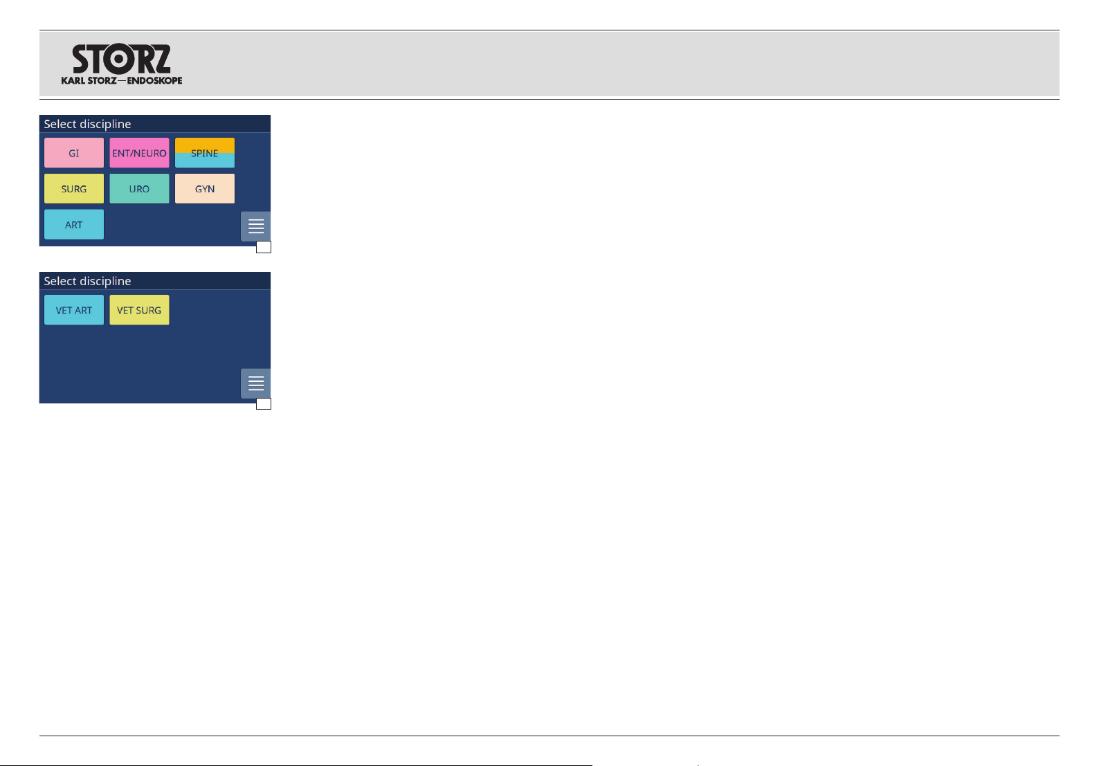
Dieses Konzept hat den Vorteil, dass das Gerät
speziell für die Bedürfnisse des Anwenders
konfigurierbar ist. Es werden z. B. nur
Einsatzgebiete angezeigt, die er nutzen möchte.
Bei Bedarf können nachträglich Fachgebiete aus
dem Bereich Humanmedizin nachgerüstet werden
(siehe Abb. 1). Ebenso besteht die Möglichkeit
ein »Advanced Softwarepaket« mit erweiterten
2
Einstellmöglichkeiten zu erwerben (siehe Seiten 26,
28, 29 und 34).
Zusatzfunktionen:
• BOOST: Bei bestimmten Anwendungen URO/
ARTHRO kann über eine BOOST-Funktion der
Spüldruck kurzzeitig erhöht werden.
• Druck- bzw. Fluss-Begrenzung: Bei bestimmten
Anwendungen kann neben der »frei« wählbaren
Haupt einstellung z. B. dem Spülfluss, der
Spüldruck begrenzt werden und umgekehrt.
5. General information
5. 1 Device description
The ENDOMAT® SELECT is a new roller pump from
KARL STORZ. Depending on the application, it can
be used for irrigation or suctioning away liquids
during interventions in a range of medical fields.
The device automatically adapts to suit the type
of operation being performed by providing optimal
operating parameters when a field-specific tubing
cartridge is inserted, assuming the device is
activated for the field of application in question.
This concept has the advantage that the device
can be configured specifically for the individual
requirements of the user. For example, only
applications which he wishes to use are displayed.
If necessary, disciplines from the field of human
medicine can be added at a later date (see Fig. 1).
An ‘Advanced software package’ with extended
setting options (see pages 26, 28, 29 and 34) can
also be purchased.
Additional functions:
• BOOST: With certain URO/ARTHRO applications,
the irrigation pressure can be increased briefly
using the BOOST function.
• Pressure/flow limitation: With certain applications,
in addition to the freely selectable main setting,
e.g., the irrigation flow rate, the irrigation pressure
can also be limited or vice versa.
5. Generalidades
5. 1 Descripción del aparato
ENDOMAT® SELECT es una nueva bomba de
rodillos de KARL STORZ. En función del campo
de aplicación, esta puede emplearse para irrigar
o succionar líquidos durante operaciones en
diferentes especialidades.
La adaptación al tipo de intervención mediante la
puesta a disposición de los parámetros de servicio
óptimos en cada caso ocurre de forma automática
al montarse un cartucho de tubos flexibles
específico para la especialidad que corresponda,
siempre que el aparato haya sido habilitado para el
campo de aplicación previsto.
Este concepto ofrece la ventaja de poder
configurar el aparato de manera específica para
las necesidades del usuario. Por ejemplo, solo se
muestran los campos de aplicación que el usuario
desea utilizar. Si es necesario, posteriormente
pueden agregarse especialidades del ámbito de la
medicina humana (véase la fig. 1). Asimismo, existe
la posibilidad de adquirir un paquete de software
“Advanced” con opciones avanzadas de ajuste
(véanse las págs. 26, 28, 29 y 34).
Funciones adicionales:
• REFUERZO: En algunas aplicaciones de URO/
ARTRO se puede incrementar la presión de
irrigación brevemente usando la función de
REFUERZO.
• Límite de presión / flujo: En algunas aplicaciones,
además del ajuste principal que puede
seleccionarse libremente como, p. ej., el flujo de
irrigación, también se puede limitar la presión de
irrigación o a la inversa.
Der ENDOMAT
Veterinärmedizin konfigurierbar (Abb. 2).
Es ist aber nicht möglich, Fachgebiete aus dem
Bereich Veterinärmedizin mit Fachgebieten aus dem
Bereich Humanmedizin zu kombinieren.
4
®
SELECT ist auch als Modell für die
The ENDOMAT
the model for veterinary medicine (Fig. 2).
However, it is not possible to combine disciplines
from the field of veterinerary medicine with
disciplines from the field of human medicine.
®
SELECT can also be configured as
El ENDOMAT
configurarse como modelo para medicina
veterinaria (fig. 2).
Sin embargo, no es posible combinar
especialidades de medicina veterinaria con
especialidades de medicina humana.
®
SELECT también puede
Page 13

Allgemeines GeneralidadesGeneral information
Die Bedienung und Kontrolle des Geräts erfolgen
über ein Touch-Display. Die Anzeige des Soll- und
Istwertes von Spüldruck bzw. Fluss erlaubt eine
Kontrolle des aktuellen Betriebszustandes. Eine
elektronische Sicherheitsschaltung blockiert die
Förderung bzw. Absaugung bei anhaltenden
Abweichungen vom Sollwert und informiert den
Benutzer über akustische Signale. Zum hohen
Sicherheitsstandard des ENDOMAT
auch ein elektronisches Auto-Check-System bei,
das die verschiedenen Systemkomponenten bei
jeder Inbetriebnahme des Geräts prüft und etwaige
Fehlerzustände signalisiert.
®
SELECT trägt
The device is operated and monitored via a touch
display. The display for the setpoint and actual
values of the irrigation pressure/flow enables
monitoring of the current operating status. An
electronic safety circuit interrupts irrigation or
suction if device performance persistently deviates
from the setpoint, and emits an audible signal
to inform the user. The high safety standard of
ENDOMAT® SELECT is further enhanced by
an electronic auto-check system, which tests
the system components each time the device
is switched on, and notifies the operator of any
failures detected.
El aparato se maneja y se monitoriza mediante
una pantalla táctil. La indicación del valor nominal
y real de la presión / del flujo de irrigación permite
monitorizar el estado actual del servicio. Un circuito
electrónico de seguridad bloquea el transporte o
la succión en caso de desviaciones persistentes
respecto del valor nominal e informa al usuario
mediante señales acústicas. Al elevado estándar
de seguridad de la ENDOMAT
asimismo un sistema electrónico de autocontrol,
que revisa los diversos componentes del sistema
cada vez que se pone en marcha el aparato y avisa
mediante señales de eventuales errores.
®
SELECT contribuye
5. 2 Schutzrechte
Dieses Produkt ist in den USA geschützt durch
(mindestens eines der folgenden) US-Patent/e
5,788,688; 6,397,286; 6,484,221; 6,824,539.
5
5. 2 Property rights
This product is protected in the USA by (at least
one of the following) US Patent No(s) 5,788,688;
6,397,286; 6,484,221; 6,824,539.
5. 2 Derechos de propiedad
Este producto está protegido en los EE. UU. por
la(s) (por lo menos una de las siguientes) patente(s)
americana(s) 5,788,688; 6,397,286; 6,484,221;
6,824,539.
Page 14

Sicherheitshinweise Instrucciones de seguridadSafety instructions
6. Sicherheitshinweise
Sicherheitshinweise sind Maßnahmen zum Schutz
des Anwenders und Patienten vor Gefährdungen,
die durch den Gebrauch des Systems entstehen
können.
6. 1 Erklärung zu Warn- und
Vorsichtshinweisen
Bitte lesen Sie diese Gebrauchsanweisung
sorgfältig durch, und beachten Sie die Anweisungen
genau. Die Bezeichnungen Warnung, Vorsicht
und Hinweis haben spezielle Bedeutungen. Wo
immer sie in der Gebrauchsanweisung verwendet
werden, sollte der nachfolgende Text genau gelesen
werden, um einen sicheren und effizienten Betrieb
des Geräts zu gewährleisten. Zur deutlicheren
Hervorhebung steht diesen Bezeichnungen
zusätzlich ein Piktogramm voran.
WARNUNG: Warnung macht auf eine
Gefährdung des Patienten oder des Arztes
3
aufmerksam. Die Nichtbeachtung einer
Warnung kann Verletzungen desPati en ten
oder des Arztes zur Folge haben.
VORSICHT: Vorsicht macht darauf
aufmerksam, dass bestimmte Wartungs-
2
oder Sicherheitsmaßnahmen zu treffen
sind, um eine Beschädigung des Geräts zu
vermeiden.
HINWEIS: Hinweise enthalten spezielle
1
Informationen zur Bedienung des Geräts, oder
sie erklären wichtige Informationen.
6. Safety instructions
Safety instructions are measures intended to
protect the user and patients from the risks which
could arise through the use of the system.
6. 1 Explanation of warnings and
cautions
Please read this manual and follow its instructions
carefully. The words Warning, Caution, and Note
convey special meanings. Wherever they are used
in this manual, they should be carefully reviewed
to ensure the safe and effective opera tion of this
product. To make the words stand out more clearly,
they are accompanied by a pictogram.
WARNING: A Warning indicates that the
personal safety of the patient or physi cian
3
may be involved. Disregarding a Warning
could result in injury to the patient or
physician.
CAUTION: A Caution indicates that partic-
ular service procedures or precautions
2
must be followed to avoid possible dam age
to the product.
NOTE: A Note indicates special informa-
1
tion about operating the product, or clar ifies
important information.
6. Instrucciones de seguridad
Las instrucciones de seguridad son medidas para
proteger al usuario y al paciente contra riesgos que
podrían originarse al utilizar el sistema.
6. 1 Explicación de las indicaciones
de alarma y advertencia
Le rogamos leer este Manual con atención y
observar estrictamente sus instrucciones. Los
términos Cuidado, Advertencia y Nota tienen
significados especiales. Cuando aparezcan en
alguna parte de este Manual de instrucciones,
revise esa sección cuidadosamente para asegurar
la operación inocua y eficaz de este aparato.
Para destacar más claramente estos términos,
los mismos están precedidos por un pictograma
adicional.
CUIDADO: El término Cuidado llama la
atención sobre una situación de peligro
3
para el paciente o para el médico. La inobservancia de este aviso podría conllevar
lesiones para el paciente o para el médico.
ADVERTENCIA: El término Advertencia
llama la atención sobre determinadas
2
medidas de mantenimiento o de seguridad
que han de llevarse a cabo a fi n de evitar el
deterioro del aparato.
NOTA: Los párrafos denominados con
1
el término Nota contienen informaciones
especiales para el manejo del equipo o
aclaran informaciones importantes.
WARNUNG: Lesen Sie diese
Gebrauchsanweisung genau durch, bevor
3
Sie das Gerät in Betrieb nehmen. Lesen Sie
besonders das Kapitel Sicherheitshinweise
aufmerksam durch, um Gefährdungen
Ihrer Patienten, Ihres Personals sowie Ihrer
eigenen Person zu vermeiden.
HINWEIS: Beschädigungen des Geräts,
1
die aufgrund von Fehlbedienungen
entstehen, fallen nicht unter die
Gewährleistungsansprüche.
6
WARNING: Read this instruction for use
thorough ly before putting the device into
3
operation. Read the section on safety
instructions carefully to avoid putting your
patients, personnel or yourself at risk.
NOTE: Any damage to the device resulting
1
from incorrect operation is not covered by the
manu facturer’s warranty.
CUIDADO: Lea detenidamente este
Manual de instrucciones antes de poner
3
en funcionamiento el aparato. Lea con
especial atención el capítulo referente a las
Instrucciones de seguridad a fi n de evitar
poner en peligro a sus pacientes, a su
personal o a usted mismo.
NOTA: Los deterioros producidos en el
1
aparato a causa de un manejo erróneo
quedan excluidos de la garantía.
Page 15

Sicherheitshinweise Instrucciones de seguridadSafety instructions
Warn- und Vorsichtshinweise Warnings and cautions Indicaciones de alarma y advertencia
WARNUNG: Die elektrischen Installationen des
Operationssaals, in dem das Gerät angeschlossen
und betrieben wird, müssen die Anforderungen der
geltenden IEC-Normen erfüllen.
3
7
WARNUNG: Gerät außerhalb der Reichweite von
Patienten aufstellen.
WARNUNG: Aus Sicherheitsgründen dürfen die
Ausgangsbuchsen des Geräts und der Patient nicht
gleichzeitig berührt werden.
WARNUNG: Die Gebrauchsanweisungen
und die Schnittstellenspezifikationen der in
Kombination verwendeten Medizinprodukte und/
oder Systemkomponenten sind genauestens zu
beachten.
WARNUNG: Eine sicherheitstechnische
Unbedenklichkeit bei Kombinationen von
Medizinprodukten ist nur dann gegeben, wenn
• diese in den jeweiligen Gebrauchsanweisungen
als solche ausgewiesen sind oder
• die Zweckbestimmung und die Schnittstellenspezifikation der in der Kombination verwendeten
Produkte dies zulässt.
WARNUNG: Das Gerät darf nur an die unten
aufgeführten Geräte angeschlossen werden, die die
Anforderungen der IEC 60601-1 erfüllen:
• CALCUSON
• UNIDRIVE
• UNIDRIVE® S III ARTHRO
WARNUNG: Rollenpumpe. Bei aktivierter Pumpe
(auch wenn diese steht) nicht in die Pumpenrollen
fassen. Eine aktivierte Pumpe kann jederzeit
anlaufen. Quetschgefahr bzw. Einzug von loser
Kleidung (Haaren) möglich.
WARNUNG: Das Gerät regelt auf den am
Ausgang der Spülpumpe gemessenen Druck.
Der intrakavitäre Druck ist aber auch vom
Höhenunterschied zwischen Gerät und Kavität
abhängig. Versuchen Sie den Unterschied so gering
wie möglich zu halten.
WARNUNG: Vermeiden Sie unbedingt ein
Eindringen von Flüssigkeit in das Gehäuse.
Lagern Sie keine Flüssigkeit auf oder direkt über
dem Gerät. Ist trotz aller Vorsichtsmaßnahmen
Flüssigkeit in das Gerät eingedrungen, sehen Sie
ausreichend Zeit zum Verdunsten vor (ebenfalls bei
Bildung von Kondenswasser).
®
S III
WARNING: The electrical installation of the
operating room in which the device is connected
and operated must comply with the applicable IEC
standards.
WARNING: Set up the device out of reach of
patients.
WARNING: For safety reasons, do not
simultaneously touch the device output sockets and
the patient.
WARNING: The instructions for use and interface
specifications for medical devices and/or system
components used in combination must be
observed precisely.
WARNING: Combinations of medical devices are
only assured to be safe if:
• they are identified as such in the particular
instructions for uses or
• the intended use and interface specifications of
the devices used in combination permit this.
WARNING: The device may only be connected to
the devices listed below, which have been shown to
comply with the requirements of IEC 60601-1:
• CALCUSON
• UNIDRIVE
• UNIDRIVE® S III ARTHRO
WARNING: Reel pump. Do not touch the pump
reels when the pump is active (even if it is not
moving). An activated pump may start moving at
any time. Danger of crushing and/or of clothes (or
hair) getting pulled into the device.
WARNING: The device controls the pressure
measured at the outlet of the irrigation pump.
The intracavitary pressure depends, among other
things, on the height difference between the device
and the cavity. Try to keep the difference as low as
possible.
WARNING: Avoid allowing fluids to enter the
housing. Do not store liquids on or directly above
the device. If, despite the precautions, liquid enters
the device, sufficient time should be planned for
evaporation (this also applies for the formation of
condensation).
®
S III
CUIDADO: La instalación eléctrica del quirófano,
donde el aparato está conectado y en servicio,
ha de cumplir con los requisitos exigidos por las
normas CEI vigentes.
CUIDADO: Instale el aparato fuera del alcance de
los pacientes.
CUIDADO: Por razones de seguridad, no se
debe entrar en contacto simultáneamente con los
conectores de salida del aparato y con el paciente.
CUIDADO: Observe con la mayor atención los
Manuales de instrucciones y las especificaciones
de interfaz de los productos médicos y/o
componentes del sistema utilizados en combinación.
CUIDADO: Una aplicación técnicamente segura,
al combinar productos médicos, puede darse
únicamente si
• estas combinaciones están indicadas expresamente como tales en los Manuales de instrucciones respectivos o
• si el uso previsto y la especificación de interfaz
de los productos utilizados en combinación lo
permiten.
CUIDADO: El aparato debe conectarse únicamente a los aparatos relacionados más abajo, los cuales cumplen los requisitos de la CEI 60601-1:
• CALCUSON
• UNIDRIVE
• UNIDRIVE® S III ARTHRO
CUIDADO: Bomba de rodillos. En caso de estar
la bomba activada (aunque esté detenida), no
toque los rodillos de la bomba con las manos.
Una bomba activada puede ponerse en marcha
en cualquier momento. Existe peligro de que las
prendas sueltas (o el cabello) queden aplastadas o
sean arrastradas.
CUIDADO: El equipo se regula a la presión medida
a la salida de la bomba de irrigación. No obstante,
la presión intracavitaria también depende de la
diferencia de altura existente entre el equipo y la
cavidad. Procure mantener la mínima distancia
posible.
CUIDADO: Evite a toda costa la infiltración de
líquido en la carcasa. No coloque líquidos sobre el
aparato o inmediatamente por encima de este. Si,
a pesar de todas las precauciones tomadas, se ha
infiltrado líquido en el aparato, prevea un tiempo
suficiente para su evaporación (también en caso de
formarse agua por condensación).
®
S III
Page 16

Sicherheitshinweise Instrucciones de seguridadSafety instructions
Warn- und Vorsichtshinweise Warnings and cautions Indicaciones de alarma y advertencia
3
WARNUNG: Vergewissern Sie sich vor dem Start
des Eingriffs, dass das eingesetzte Schlauchset
weder undicht noch abgeknickt ist, und dass die
Schlauchenden sicher befestigt sind.
WARNUNG: Seien Sie vorsichtig beim Einlegen
der Schlauchkassette. Ein gequetschter
Pumpenschlauch führt dazu, dass das
Sicherheitssystem die Pumpe stoppt.
WARNUNG: Der Service darf nur durch eine von
KARL STORZ autorisierte Fachkraft durchgeführt
werden.
WARNUNG:
Anwen dung auf seine Funktionsfähigkeit. Bei
offensichtlichen Schäden darf das Gerät nicht
verwendet werden.
WARNUNG: Beachten Sie bei der Entsorgung
von Zubehör die länderspezifischen Vorschriften/
Gesetze.
WARNUNG: Das Gerät nur innerhalb der
festgelegten Umweltbedingungen betreiben.
WARNUNG: Das Gerät kann plötzlich ausfallen. Sie
sollten daher die Bereitstellung eines Ersatzgeräts
oder alternative Verfahren einplanen, wenn die
Anwendung gesteuerten Flüssigkeitstransport
erfordert.
WARNUNG: Gerät nicht öffnen! Gefahr eines
elektrischen Schlags. Lassen Sie Servicearbeiten
nur durch den Hersteller oder vom Hersteller
autorisiertes Personal durchführen (vgl. §3
Medizinprodukte-Betreiberverordnung). Jedes
Öffnen des Geräts durch unautorisiertes Personal
führt zum Erlöschen der Garantie.
WARNUNG: Um das Risiko eines elektrischen
Schlages zu vermeiden, darf dieses Gerät nur an
ein Versorgungsnetz mit Schutzleiter angeschlossen
werden.
WARNUNG: Das Gerät ist nur vollständig von der
Netzspannung getrennt, wenn der Netzstecker
abgezogen ist.
Prüfen Sie dieses Gerät vor jeder
WARNING: Before you start the intervention,
make sure that the tubing set used is not leaking or
kinked and that the ends of the tubes are properly
secured.
WARNING: Be carefully when inserting the tubing
cartridge. A squeezed pump hose can cause the
safety system to stop the pump.
WARNING: Servicing may only be performed by
specialists authorized by KARL STORZ.
WARNING: Test this device prior to each surgical
procedure to ensure that it is functioning correctly.
It should not be used if any damage is evident.
WARNING: Follow the country-specific regulations/
laws for the disposal of accessories.
WARNING: The device may only be operated
within specified environmental conditions.
WARNING: The device may be subject to sudden
failures. Keep a spare device at hand or alternate
procedures in mind if the intervention requires
controlled fluid transportation.
WARNING: To avoid the risk of electrical shock,
do not open the unit. Refer servicing to the
manufacturer or to personnel authorized by the
manufacturer. Any opening of the device by
unauthorized persons will void warranty claims.
WARNING: To avoid the risk of an electric shock,
this equipment must only be connected to a supply
mains with protective earth.
WARNING: The line voltage to the device is only
definitively disconnected once the power plug has
been unplugged.
CUIDADO: Antes de iniciar la intervención,
cerciórese de que el set de tubos flexibles utilizado
no presente fugas ni esté doblado y los extremos
de los tubos flexibles estén bien fijados.
CUIDADO: Proceda con cuidado al insertar el
cartucho de tubos flexibles. Si un tubo flexible de
la bomba está aplastado, el sistema de seguridad
detiene la bomba.
CUIDADO: Las tareas de servicio técnico deben
ser llevadas a cabo únicamente por personal
autorizado por KARL STORZ.
CUIDADO:
funcionamiento de este aparato antes de cada
aplicación. No debe utilizarse el aparato si presenta
deterioros evidentes.
CUIDADO: Observe la legislación vigente, tanto
local como estatal, en materia de gestión de
residuos.
CUIDADO: El aparato solo puede utilizarse dentro
de las condiciones ambientales especificadas.
CUIDADO: El aparato puede fallar repentinamente.
Por esta razón, usted debe planificar un equipo
de repuesto a disposición o procedimientos
alternativos si la aplicación requiere un transporte
de líquidos controlado.
CUIDADO: No abra el aparato. Peligro de
descarga eléctrica. Los trabajos de servicio técnico
deben encargarse únicamente al fabricante o
a personal autorizado por el fabricante. Si el
equipo es abierto por personas no autorizadas, se
extinguirán los derechos de garantía.
CUIDADO: A fin de evitar el riesgo de una
descarga eléctrica, este aparato solo puede
conectarse a una red de alimentación con
conductor de protección.
CUIDADO: El aparato solo está completamente
desconectado de la corriente eléctrica cuando se
haya extraído el enchufe de la red.
Compruebe la capacidad de
8
Page 17

Sicherheitshinweise Instrucciones de seguridadSafety instructions
Warn- und Vorsichtshinweise Warnings and cautions Indicaciones de alarma y advertencia
3
WARNUNG: Nicht im Umfeld eines Kernspintomographen (MRT) verwenden. Dieses Gerät ist für die
Kernspintomographie ungeeignet.
WARNUNG: Der ENDOMAT
verwendet werden, wenn Geräte für MRT, CT,
Diathermie, Elektrokauterisation oder RFID elektromagnetische Störungen verursachen könnten.
Ist sich der Benutzer unsicher oder vermutet, dass
Geräte dieser Art technische Probleme verursachen
könnten, sollte der klinische/biomedizinische Techniker der Einrichtung zu Rate gezogen werden.
WARNUNG: Um zu vermeiden, dass unbekannte
Quellen elektromagnetischer Störungen die Funktion elektrischer klinischer Geräte beeinträchtigen,
wird dringend empfohlen, einen Ad-Hoc-Test der
HF-Strahlung von einem klinischen/biomedizinischen Ingenieur oder einem EMV-Fachmann
durchführen zu lassen.
WARNUNG: Zusätzliche Geräte, die mit
elektrischen Medizingeräten verbunden
werden, müssen mit den entsprechenden
IEC oder ISO Standards (z. B. IEC 60950 für
Datenverarbeitungsgeräte) übereinstimmen.
Des Weiteren müssen alle Konfigurationen den
Anforderungen für medizinisch elektrische Systeme
entsprechen (siehe IEC 60601-1-1 bzw. Absatz 16
der 3. Edition der IEC 60601-1). Jeder, der
zusätzliche Geräte an elektrische Medizingeräte
anschließt, konfiguriert ein medizinisches System
und ist daher verantwortlich, dass das System
den Anforderungen für medizinisch elektrische
Systeme entspricht. Es ist zu beachten, dass die
lokale Rechtsvorschrift Vorrang gegenüber den
oben genannten Anforderungen hat. Bei Zweifeln
kontaktieren Sie Ihren Vertreter vor Ort oder den
technischen Kundendienst.
WARNUNG: Die richtige Konfiguration des Geräts
muss nach jedem Software-Update überprüft
werden.
®
SELECT darf nicht
WARNING: Do not use in a magnetic resonance
(MR) environment. This device is MR Unsafe.
WARNING: The ENDOMAT
used where MRI, CT, Diathermy, Electrocautery
or RFID equipment may cause Electromagnetic
interference (EMI). If the user is unsure or suspects
that such equipment may be causing technical
problems, the clinical/biomedical engineer of the
facility should be consulted.
WARNING: To prevent electrical medical device
equipment from being adversely effected by
unknown sources of electromagnetic interference,
it is highly recommended that Ad hoc radiated
RF testing be conducted by a Clinical/Biomedical
engineer or an EMC professional.
WARNING: Additional devices which are
connected to electrical medical devices must
comply with the relevant IEC or ISO standards
(e.g., IEC 60950 for data processing devices).
Furthermore, all configurations must comply with
the requirements for medical electrical systems
(see IEC 60601-1-1 or para 16 of the 3rd edition
of the IEC 60601-1). Anybody connecting
additional devices to electrical medical devices
is configuring a medical system, and is therefore
responsible for ensuring that the system complies
with the standard requirements for medical
electrical systems. It should be noted that the
local legal regulations have priority over the abovementioned requirements. If in doubt, contact your
representative on site or the technical customer
service.
WARNING: The correct configuration of the device
must be checked after each software update.
®
SELECT is not to be
CUIDADO: No utilice el aparato en un entorno
de resonancia magnética (RM). Este aparato está
clasificado como No seguro para RM (MR Unsafe).
CUIDADO: No se debe utilizar el ENDOMAT
SELECT ante la posibilidad de interferencia
electromagnética (EMI) provocada por TRM, TC,
diatermia, electrocauterización o equipos de RFID.
Si el usuario está inseguro o sospecha que dicho
aparato pueda estar causando problemas técnicos,
se debe consultar al ingeniero clínico/biomédico del
centro sanitario.
CUIDADO:
de interferencia electromagnética afecten de manera
adversa al equipo de aparatos médicos eléctricos,
se recomienda firmemente la realización de una
prueba de radiofrecuencia radiada por parte de un
ingeniero clínico/biomédico o un experto de CEM.
CUIDADO: Los aparatos adicionales que se
conectan a equipos electromédicos han de contar
con una certificación que acredite el cumplimiento
de las normas CEI o ISO correspondientes (p. ej.,
CEI 60950 para aparatos procesadores de datos).
Además, todas las configuraciones han de cumplir
los requisitos para sistemas electromédicos (véase
la CEI 60601-1-1 o la sección 16 de la 3ª edición
de la CEI 60601-1). Toda persona que conecte
aparatos adicionales a aparatos electromédicos
está configurando un sistema médico y es, por
lo tanto, responsable de que el sistema cumpla
con los requisitos para equipos electromédicos.
Obsérvese que la legislación nacional o regional
tiene prioridad sobre los requisitos indicados más
arriba. En caso de duda le rogamos dirigirse a
su representante local correspondiente o bien a
nuestro departamento de servicio técnico.
CUIDADO: Se debe comprobar la correcta
configuración del aparato tras cada actualización
de software.
Para evitar que fuentes desconocidas
®
9
Page 18

Sicherheitshinweise Instrucciones de seguridadSafety instructions
Machen Sie sich vor der ersten Anwendung
des Geräts am Patienten unbedingt mit der
Funktionsweise und Bedienung des Geräts vertraut.
6. 2 Zweckbestimmung
Saug-/Spülpumpen und deren Zubehör dienen
zum Einbringen von Spülflüssigkeiten in Organe,
Gelenke und auf Operationsfelder sowie zum
Absaugen von Spül- und Körperflüssigkeiten,
Sekreten, Gewebe und Gasen bei diagnostischen
oder therapeutischen Eingriffen.
Indikation
Saug-/Spülpumpen mit dem entsprechenden
Zubehör eignen sich für all jene diagnostischen
sowie therapeutischen Eingriffe, welche
die im Kapitel 9.4 »Technische Daten« vom
Gerät bereitgestellten Energien und Stoffe zur
erfolgreichen Durchführung benötigen.
Das Gerät stellt Spül- oder Saugfunktionen für
mehrere Indikationen bereit:
• Urologie
• Gynäkologie
• Chirurgie (Thorakoskopie, Laparoskopie und
Proktologie)
• Arthroskopie
• Gastroenterologie
• Objektivspülung z. B. während FESS (Funktionelle
endoskopische Nasennebenhöhlen-Chirurgie)
• Wirbelsäulenchirurgie
Before using the device on the patient, it is imperative that you be acquainted with how the device
operates and is controlled.
6. 2 Intended use
Suction/irrigation pumps and their accessories
are used for the introduction of irrigation fluids into
organs, joints and operating fields as well as the
suctioning off of irrigation fluids and bodily fluids,
secretions, tissue and gas during diagnostic or
therapeutic interventions.
Indication
Suction and irrigation pumps with the
corresponding accessories are suitable for all
diagnostic or therapeutic interventions which require
the energy and substances provided by the device
as per section 9.4 ‘Technical data’ for successful
implementation.
The device provides irrigation and suction functions
for a range of indications:
• Urology
• Gynecology
• Surgery (Thoracoscopy, Laparoscopy and
Proctology)
• Arthroscopy
• Gastroenterology
• Lense Cleaning e.g. during FESS
• Spine surgery
Familiarícese bien con los modos de
funcionamiento y el manejo del equipo antes de
emplearlo por primera vez con un paciente.
6. 2 Uso previsto
Las bombas de succión e irrigación y sus
accesorios se utilizan para aplicar líquidos de
irrigación en órganos, articulaciones y campos
operatorios, así como para succionar líquidos de
irrigación y corporales, secreciones, tejidos y gases
en intervenciones diagnósticas o terapéuticas.
Indicaciones
Las bombas de succión e irrigación junto con
los accesorios correspondientes son adecuadas
para todas aquellas intervenciones con fines
diagnósticos y terapéuticos que requieran las
energías y sustancias proporcionadas por el
aparato según el capítulo 9.4 “Datos técnicos” para
alcanzar los fines previstos.
El aparato proporciona funciones de irrigación o
succión para varias aplicaciones:
• Urología
• Ginecología
• Cirugía (toracoscopia, laparoscopia y proctología)
• Artroscopia
• Gastroenterología
• Enjuague del objetivo, p. ej., durante FESS
(cirugía funcional endoscópica de los senos
paranasales)
• Cirugía de la columna vertebral
10
Page 19

Sicherheitshinweise Instrucciones de seguridadSafety instructions
Warn- und Vorsichtshinweise Warnings and cautions Indicaciones de alarma y advertencia
Intended useZweckbestimmung
Uso previsto
Kontraindikation
Der Einsatz ist kontraindiziert, wenn nach
Einschätzung des behandelnden Arztes das Gerät
aufgrund seiner technischen Ausführung nicht
mit dem erfolgreichen Abschluss des geplanten
Eingriffes vereinbar ist.
Das Zubehör darf nur mit den dafür vorgesehenen
Geräten verwendet werden. Allgemein dürfen
Medizinprodukte nicht verwendet werden
bei Patienten, welche nicht dem definierten
Patientenkreis angehören oder wenn die OP selbst
als kontraindiziert gilt.
Der Einsatz von Pumpensystemen ist dann
kontraindiziert, wenn nach Einschätzung
des behandelnden Arztes die OP-Methode
kontraindiziert
Allgemeinzustands des Patienten die OPbzw. Narkosefähigkeit nicht gegeben ist.
Pumpensysteme dürfen nicht für Eingriffe in
direktem Kontakt mit dem ZNS (Zentralen
Nervensystem) und zentralen Herzkreislaufsystem
verwendet werden.
Saug- und/oder Spülpumpen ohne
Drucküberwachung dürfen nicht für die Dilatation
von Hohlorganen und Gelenken verwendet werden.
Das Gerät darf nicht bei der ERCP und
Cholangioskopie (Gastro), Spine lumbar
(interlaminarer Zugang), Spine zervical sowie bei
allen Anwendungen, die einen nicht-pulsatilen Fluss
benötigen, eingesetzt werden.
Ebenfalls darf das Gerät nicht zur Zufuhr von
Medikamenten oder zur Thorax Drainage eingesetzt
werden.
ist oder aufgrund des
Contraindication
Use is contraindicated if, in the opinion of the
attending physician, the device is not compatible
with successful completion of the planned
intervention due to its technical design.
The accessories must only be used with the
intended devices. In general, medical devices must
not be used on patients who are not part of the
defined patient group, or if the operation itself is
contraindicated.
The use of pump systems is contraindicated if, in
the opinion of the attending physician, the surgical
method as such is contraindicated, or if the patient
is not able to undergo surgery or anesthesia due to
his or her general condition.
Pump systems must not be used for interventions
in direct contact with the central nervous system
(CNS) and central cardiovascular system.
Suction and/or irrigation pumps without pressure
monitoring must not be used for dilations of hollow
organs or joints.
The device must not be used for ERCP and cholangioscopy (gastro), the lumbar spine (interlaminar
approach), cervical spine as well as all applications
which require a non-pulsatile fl ow.
Likewise, the device must not be used to administer
medication. Nor may it be used for thoracic
drainage.
Contraindicaciones
La aplicación está contraindicada cuando, según
la opinión del médico encargado del tratamiento, la
ejecución técnica del aparato no contribuiría al éxito
final de la intervención planeada.
Utilice los accesorios únicamente con los aparatos
previstos para ello. Como regla general, no se
deben utilizar productos médicos en pacientes que
no se ajusten a la definición del grupo de pacientes
o cuando la intervención quirúrgica en sí esté
contraindicada.
La utilización de sistemas de bombas está
contraindicada cuando, según la opinión del
médico encargado del tratamiento, el método
quirúrgico en sí esté contraindicado
estado general del paciente, no pueda administrarse
anestesia o practicarse cirugía.
Los sistemas de bombas no deben utilizarse en
intervenciones que requieran contacto directo
con el SNC (sistema nervioso central) y el sistema
circulatorio central.
No deben utilizarse bombas de succión y/o
irrigación sin monitorización de la presión para la
dilatación de órganos huecos y articulaciones.
El aparato no debe utilizarse para la
colangiopancreaticografía retrógrada endoscópica
(CPRE) y la colangioscopia (Gastro), la columna
lumbar (vía de acceso interlaminar), la columna
cervical ni para todas las aplicaciones que requieran
un flujo no pulsátil.
Asimismo, el aparato no debe emplearse para la
administración de medicamentos o para practicar
un drenaje torácico.
o, debido al
11
Page 20

Sicherheitshinweise Instrucciones de seguridadSafety instructions
Indicaciones de alarma y advertenciaIntended useZweckbestimmung
Uso previsto
Der ENDOMAT® SELECT ist eine Rollenpumpe, die
entweder als Spül- oder als Saugpumpe für den
Einsatz bei diagnostischen und therapeutischen
Eingriffen bestimmt ist. Die Applikation erfolgt über
anwendungsspezifische Saug-/Spülinstrumente.
Die Verwendung des Geräts anders als oben
bestimmt ist aus Sicherheitsgründen nicht zulässig.
Der ENDOMAT
Schlauchkassetten bzw. Schlauchsets und
Zubehörteilen betrieben werden, die von
KARL STORZ für das Gerät als geeignet be zeich net
werden.
Insbesondere folgende schwerwiegende Fehler
können auftreten:
• Unzureichender Halt auf den
Schlauchkonnektoren bedeutet Sterilitätsverlust
und kann Beschädigung des Geräts durch
eingedrungene Flüssigkeit zur Folge haben.
• Frühzeitiger Bruch des Pumpenschlauch-
segments sowie dadurch bedingter Sterilitätsverlust und Beschädigung des Geräts durch
eingedrungene Flüssigkeit.
• Anzeige einer falschen Ist-Förderrate durch
Abweichungen im Schlauchdurchmesser.
®
SELECT darf nur mit
WARNUNG: Bei Verwendung anderer als
der vorgeschriebenen Schlauchsysteme
3
kann keine Gewähr für die sichere Funktion
des Geräts übernommen werden.
WARNUNG: Eine Änderung des
medizinischen elektrischen (ME) Geräts
3
istnicht erlaubt.
®
The ENDOMAT
intended for use either as an irrigation or suction
pump in diagnostic or therapeutic interventions.
Theapplication must be carried out using
appropriate suction/irrigation instruments.
Use of the device in fields other than those
indicated above is not allowed for safety reasons.
The ENDOMAT
with tubing cartridges or tubing sets and
accessories which have been designated as
suitable for the device by KARL STORZ.
3
The following serious defects may arise in particular:
• Inadequate grip on the tube connectors means a
loss of sterility and may lead to the device being
damaged by ingress of liquid.
• Premature breakage of the pump tube segment
and consequent loss of sterility and damage to
the device caused by ingress of liquid.
• Display of an incorrect actual irrigation rate due
to deviations in tube diameter.
3
SELECT is a roller pump which is
®
SELECT may only be operated
WARNING: No responsibility for the safe
operation of the device can be accepted
if any tubing system other than those
specified are used.
WARNING: No modification of this
equipment is allowed.
La ENDOMAT® SELECT es una bomba de rodillos,
la cual está prevista para utilizarse como bomba
de irrigación o de succión en intervenciones
diagnósticas o terapéuticas. La aplicación se
efectúa con instrumentos específicos de succión e
irrigación.
Por motivos de seguridad, no está permitida la
utilización del aparato de forma diferente de la arriba
indicada.
La ENDOMAT
utilizada con los cartuchos / sets de tubos flexibles
y las piezas accesorias que KARL STORZ haya
indicado como idóneos para este equipo.
Pueden producirse los siguientes fallos graves:
• Apoyo insuficiente en los conectores del tubo
flexible, lo que supone la pérdida de esterilidad y
puede ocasionar deterioros en el aparato debido
a la infiltración de líquido.
• Rotura del segmento de tubo flexible de la bomba
en un estadio temprano, así como la consiguiente
pérdida de esterilidad y deterioro del aparato
debido a la infiltración de líquido.
• Indicación de un flujo de bombeo real erróneo
debido a desviaciones en el diámetro del tubo
flexible.
®
SELECT solamente puede ser
CUIDADO: En el caso de utilizarse otros
sistemas de tubos fl exibles diferentes a los
3
prescritos, no se podrá asumir ninguna
garantía en cuanto a la seguridad de
funcionamiento del equipo.
CUIDADO: No está permitido realizar
modifi cación alguna en el aparato
3
electromédico (EM).
12
Page 21

Sicherheitshinweise Instrucciones de seguridadSafety instructions
6. 3 Qualifikation des Anwenders
Der ENDOMAT® SELECT darf nur von Ärzten und
medizinischem Assistenzpersonal angewendet
werden, die über eine entsprechende fachliche
Qualifikation verfügen und am Gerät eingewiesen
sind.
6. 4 Einweisung in die
Gerätefunktion und Bedienung
Die Einweisung darf nur durch solche Personen
erfolgen, die aufgrund ihrer Kenntnisse dazu
geeignet sind.
Die zuständige Gebietsvertretung oder der
zuständige KARL STORZ Vertreter steht für die
Einweisung bei Ihnen und für Auskunft über weitere
Schulungsalternativen zur Verfügung.
6. 5 Patientenpopulation
6. 5. 1 SURG, URO, ART, SPINE, ENT/NEURO,
GI, VET
Geschlecht: irrelevant
Alter: irrelevant
Gewicht: irrelevant
Nationalität: irrelevant
Gesundheitszustand: entsprechend der
Einschätzung des Arztes geeignet für die
Behandlung
6. 5. 2 GYN
Geschlecht: weiblich
Alter: irrelevant
Gewicht: irrelevant
Nationalität: irrelevant
Gesundheitszustand: entsprechend der
Einschätzung des Arztes geeignet für die
Behandlung
6. 3 User qualification
The ENDOMAT® SELECT may only be used by
physicians and medical assistants who have a
correspond ing specialized qualification and who
have been instructed in use of the device.
6. 4 Training in the operation and
function of the device
Training should only be provided by persons
equipped to do so on the basis of their skills.
Your local representative or responsible
KARL STORZ member of staff is available to
provide training on your premises and to give you
information about further training options.
6. 5 Patient profile
6. 5. 1 SURG, URO, ART, SPINE, ENT/NEURO,
GI, VET
Gender: irrelevant
Age: irrelevant
Weight: irrelevant
Nationality: irrelevant
State of health: suitable for endoscopic
interventions, in the physician's judgment
6. 5. 2 GYN
Gender: female
Age: irrelevant
Weight: irrelevant
Nationality: irrelevant
State of health: suitable for endoscopic
interventions, in the physician's judgment
6. 3 Cualifi cación del usuario
La ENDOMAT® SELECT solo puede ser empleada
por médicos y personal de asistencia médica
que dispongan de una cualificación profesional
adecuada y que hayan recibido instrucciones sobre
la utilización del aparato.
6. 4 Formación acerca de las funciones delaparatoysu manejo
Únicamente las personas que por sus
conocimientos estén capacitadas para ello deben
encargarse de impartir la instrucción en el manejo
del aparato.
Su representante local o el responsable
correspondiente de KARL STORZ están
gustosamente a su disposición para impartir
esta instrucción en las instalaciones que usted
determine y para proporcionarle información
respecto a otras alternativas de formación.
6. 5 Población de pacientes
6. 5. 1 SURG, URO, ART, SPINE, ENT/NEURO,
GI, VET
Sexo: irrelevante
Edad: irrelevante
Peso: irrelevante
Nacionalidad: irrelevante
Estado de salud: adecuado para la aplicación,
según la evaluación del médico
6. 5. 2 GYN
Sexo: femenino
Edad: irrelevante
Peso: irrelevante
Nacionalidad: irrelevante
Estado de salud: adecuado para la aplicación,
según la evaluación del médico
13
Page 22

Sicherheitshinweise Safety instructions
Instrucciones de seguridad
6. 6 Vorgesehene Einsatzgebiete
am Patienten
SURG: Abdomen, Thorax, Prokto
GYN: Uterus
URO: unterer und oberer Harntrakt
ART: Gelenke in Fuß, Knie, Hüfte,
Schulter, Hand oder Finger
SPINE: Thorakale und lumbale Wirbelsäule
ENT/NEURO: Linsenreinigung bei endoskopisch
assistierter FESS-Chirurgie sowie
bei endoskopisch assistierter Mikro-
Neurochirurgie, und transnasaler
Hypophysen-Chirurgie
GI: oberer und unterer
Gastrointestinaltrakt
6. 6 Intended region of treatment
onthe patient
SURG: Abdomen, thorax, pelvis
GYN: Uterus
URO: Upper and lower urinary tract
ART: Joints in the foot, knee, hips,
shoulder, hand and finger
SPINE: Thoracic and lumbar vertebral
column
ENT/NEURO: Lens cleaning with endoscopically
assisted FESS surgery as well
as with endoscopically assisted
microneurosurgery and transnasal
pituitary gland surgery
GI: Upper and lower gastrointestinal
tract
6. 6 Zonas previstas de aplicación
en el paciente
SURG: abdomen, tórax, proctología
GYN: Útero
URO: Tracto urinario inferior y superior
ART: Articulaciones en el pie, rodilla,
cadera, hombro, mano o dedos de
la mano
SPINE: Columna torácica y lumbar
ENT/NEURO: Limpieza de las lentes en cirugía
FESS asistida endoscópicamente,
así como en microneurocirugía
asistida endoscópicamente y en
cirugía de la hipófisis transnasal
GI: Tracto gastrointestinal superior e
inferior
14
Page 23

Sicherheitshinweise Instrucciones de seguridadSafety instructions
6. 7 Anwenderprofil Arzt und
Assistenzpersonen
Anerkannte medizinische Grundkenntnisse der
Anwendung (Facharzt, medizinische Fachkraft)
Ausreichende Auffassungsgabe zur rationalen
Beurteilung der aktuellen Situation
Vertrautheit im Umgang mit technischen Apparaten
Ausreichende Kenntnisse einer der vom Gerät und
der Gebrauchsanweisung verwendeten Sprache
Mindestens eine umfassende Einweisung in die
Bedienung des Geräts
Keine körperlichen Behinderungen die eine
Wahrnehmung von akustischen oder optischen
Signalen beeinträchtigen oder verhindern.
6. 8 Vorgesehene
Einsatzbedingungen
6. 8. 1 Gebrauch
Das Gerät ist für den Einsatz in Kliniken und
Praxen vorgesehen. Die technischen Daten
und Umgebungsbedingungen sind in der
Gebrauchsanweisung beschrieben.
6. 8. 2 Weitere vorgesehene Bedingungen
Verwendungshäufigkeit: ein bis mehrmals täglich
Gebrauchsdauer: von mehreren Minuten bis zu
mehreren Stunden täglich
Aufstellungsort: Positionierung auf einer ebenen,
vibrationsfreien Unterlage
Beweglichkeit: kann, wenn auf einem Wagen
positioniert, bewegt werden
Kombination: kann mit anderen für die Operationen
notwendigen Geräten gleichzeitig am Patienten
eingesetzt werden
Steuerung: kann über den KARL STORZ-SCB
angesteuert werden.
6. 7 User profile of physician and
assistants
Training: recognized medical skills in the field of
application (specialist physician, qualified medical staff)
Intelligence: adequate powers of comprehension to
rationally assess the situation in hand
Ability to act: familiarity with the use of technical
apparatus
Language: Suitable command of one of the languages
used by the device and in the instruction manual.
Experience: at least one comprehensive session of
training in the use of the device.
Impairments: no physical impairment which makes
it difficult or impossible to perceive acoustic or visual
signals.
6. 8 Intended conditions of use
6. 8. 1 Use
The device is intended for use in clinics and
practices. The technical data and ambient
conditions are described in the instruction manual.
6. 8. 2 Other intended conditions
Frequency of use: one or more times a day
Length of use: from a few minutes to several hours
a day.
Place of installation: Positioning on a level, vibration-
free surface
Mobility: can be moved if positioned on a cart
Combination: can be used on the patient at the
same time as other equipment required for the
operations
Control: can be controlled via the KARL STORZSCB.
6. 7 Perfi l de usuario del médico y
del personal auxiliar
Conocimientos médicos convalidados de la
aplicación (médico especialista, personal médico
especializado)
Facultad de comprensión suficiente para una
evaluación racional de la situación actual
Familiaridad con el manejo de aparatos técnicos
Conocimientos suficientes de uno de los
idiomas utilizados por el aparato y el Manual de
instrucciones
Como mínimo, una instrucción exhaustiva en el
manejo del aparato
Ausencia de impedimentos físicos que puedan
menoscabar o impedir la percepción de señales
visuales o acústicas.
6. 8 Condiciones previstas de
aplicación
6. 8. 1 Empleo
El aparato está previsto para su aplicación en
clínicas y consultorios médicos. Los datos técnicos
y las condiciones ambientales están descritos en el
Manual de instrucciones.
6. 8. 2 Otras condiciones previstas
Frecuencia de uso: de una a varias veces al día
Duración de la aplicación: desde varios minutos
hasta varias horas al día
Lugar de emplazamiento: posicionamiento sobre
una superficie plana, sin vibraciones
Movilidad: puede ser desplazado si está colocado
sobre una unidad móvil
Combinación: puede utilizarse en el paciente
simultáneamente con otros aparatos necesarios
para la intervención quirúrgica
Control: puede controlarse a través del
KARL STORZ-SCB
15
Page 24
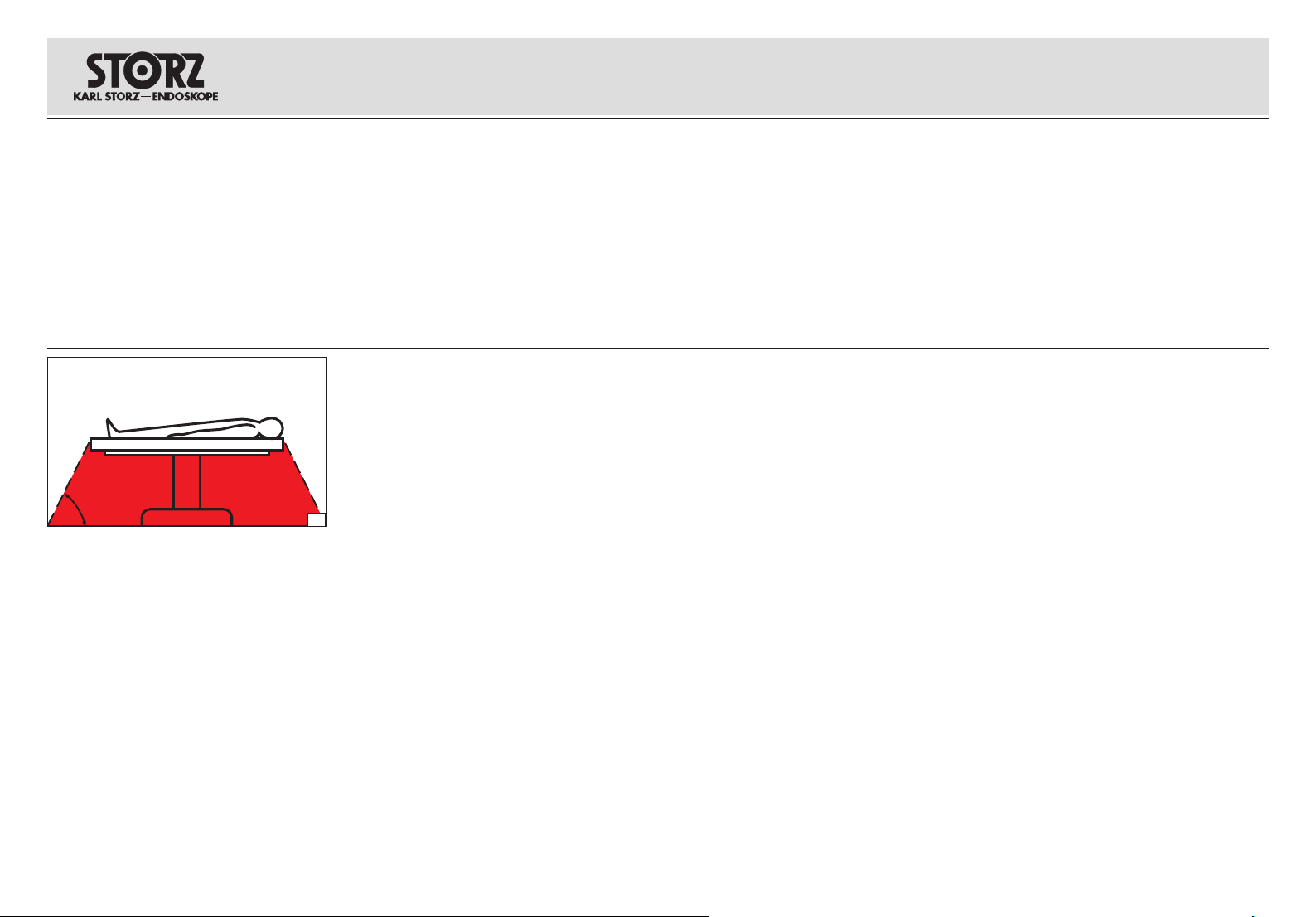
Sicherheitshinweise Instrucciones de seguridadSafety instructions
60°
6. 9 Position des Anwenders
Für die Bedienung des Geräts steht der Anwender
innerhalb eines Sichtkegels mit Öffnungswinkel
von ±45° vor dem Gerät in einer Distanz von ca.
30 – 70 cm zur Frontplatte.
Für die Beobachtung der Ist-Werte während der
Anwendung wird von einer Sichtdistanz zum Gerät
von 2 m ausgegangen (die Schlauchlänge beträgt
2 m).
6. 10 Sicherheitsmaßnahmen
am Aufstellort
Das Gerät darf nur in medizinisch genutzten
Räumen benutzt werden, deren elektrische Anlagen
nach den national gültigen Vorschriften installiert
sind.
WARNUNG: Verwenden Sie das Gerät
NICHT, wenn sich zündfähige Narkosegase
3
in der unmittelbaren Umgebung des Geräts
3
befinden.
WARNUNG: Das Gerät ist nicht für
den Betrieb in explosionsgefährdeten
3
Bereichen bestimmt. Bei Verwendung
von explosionsfähigen Narkosegasen
darf das Gerät nicht in der dargestellten
Gefahrenzone betrieben werden (Abb.3).
WARNUNG: Das Gerät darf nicht in
sauerstoffangereicherter Umgebung
3
eingesetzt werden.
Dieses gilt auch für leicht brennbare und explosionsfähige Chemikalien, z. B. Hautdesinfektions- und
Flächen schnell desinfektions mittel.
Das Gerät ist mit einer Steckvorrichtung für
den Potentialausgleich ausgerüstet. Diese nach
Maßgabe der national gültigen Vorschriften
anschließen.
6. 9 User position
For operation, the user should always be standing
in front of the device within a 'cone of vision' with
an opening angle of ±45° at a distance of approx.
30 – 70 cm to the front panel.
For observation of the actual values during the
application, a visual distance from the device of 2 m
is assumed (the tube length is 2 m).
6. 10 Safety precautions at
the siteofinstallation
The device may only be used in medical rooms in
which the electrical equipment has been installed in
accordance with applicable national regulations.
WARNING: DO NOT use the device in the
presence of flammable anesthetics.
3
WARNING: The device is not intended for
use in potentially explosive zones. Do not
3
operate the device within the demarcated
hazard zone while explosive anesthetic
gases are in use (Fig.3).
WARNING: The device must not be used
in oxygenated environments.
3
This also applies for easily combustible and
explosive chemicals, e.g. skin disinfectants and
fast-acting surface disinfectants.
The device is equipped with a connector for
attaching a ground line. It should be connected
up in accordance with the applicable national
regulations.
6. 9 Posición del usuario
Para el manejo del aparato, el usuario está dentro
de un cono visual con un ángulo de abertura de
±45°, delante del aparato, a una distancia de aprox.
30 a 70 cm con respecto a la placa frontal.
Para la observación de los valores reales durante
la aplicación, se presupone una distancia visual
de 2 m hasta el aparato (la longitud de los tubos
flexibles alcanza 2 m).
6. 10 Medidas de seguridad en el
lugar de emplazamiento
El equipo solo podrá ser utilizado en espacios
médicos cuya instalación eléctrica haya sido
efectuada de acuerdo con las normas nacionales
vigentes.
CUIDADO: NO utilice el aparato si existen
gases anestésicos infl amables en las
3
inmediaciones del aparato.
CUIDADO: El producto no está previsto
para ser utilizado en áreas expuestas a
3
posibles explosiones. Si se emplean gases
anestésicos explosivos, no podrá utilizarse
el aparato en las zonas califi cadas como
peligrosas por este motivo (fi g.3).
CUIDADO: El aparato no debe ser utilizado
en un ambiente enriquecido con oxígeno.
3
Esto es válido también para productos químicos
fácilmente inflamables y explosivos tales como,
p. ej., productos para desinfección de la piel y
desinfectantes rápidos para superficies.
El equipo está provisto de un enchufe para
conexión equipotencial. La conexión ha de
efectuarse de acuerdo con las normativas
nacionales vigentes.
16
Page 25

Sicherheitshinweise Instrucciones de seguridadSafety instructions
6. 11 Sicherheitsmaßnahmen beim
Einsatz des Geräts
Der Anwender hat sich vor der Anwendung
des Geräts von der Funktionssicherheit und
dem ordnungsgemäßen Zustand des Geräts zu
überzeugen.
Während der Behandlung mit dem ENDOMAT
SELECT muss der Patient mit der üblichen
medizinischen Sorgfalt be handelt und beobachtet
werden. Dies schließt die Verlaufskontrolle des
Be hand lungs vorgangs, die Überwachung der
Vitalwerte und der Narkose mit ein.
Jeder Behandlungsvorgang darf nur durchgeführt
werden, wenn die visuelle Beobachtung der
Gerätewirkung sichergestellt ist.
®
6. 12 Sicherheitseinrichtungen
Der ENDOMAT® SELECT verfügt über folgende
Sicherheitseinrichtungen:
6. 12. 1 Selbstprüfung
Die Selbstprüfung wird bei jedem Einschalten des
Geräts durchgeführt. Fällt einer der Tests negativ
aus, wird eine entsprechende Fehlermeldung
angezeigt.
6. 12. 2 Test des Touch-Displays
Nach dem Einschalten der Versorgungsspannung
wird ein KARL STORZ Logo mit dem Gerätenamen
für ein paar Sekunden, abhängig von der Ladezeit
des Betriebssystems, angezeigt (Abb. 4).
6. 11 Safety precautions when
operating the device
It is the user’s responsibility to make sure the device
is safe and operates properly before using it.
During treatment with the ENDOMAT
patient must be treated and kept under observation
with the usual medical care. This includes keep ing
a check on the progress of treatment, as well as
monitoring the vital levels and the anesthetic effects.
Any treatment may only be performed if visual
observation of the device is ensured.
®
SELECT the
6. 12 Safety features
The ENDOMAT® SELECT is equipped with the
following safety features:
6. 12. 1 Self-test
A self-test is performed each time the device
is switched on. If any of the tests is negative, a
corresponding error message is displayed.
6. 12. 2 Testing the touch display
After switching on the supply voltage, a
KARL STORZ logo with the device name is
displayed for a few seconds, depending on the
loading time of the operating system (Fig. 4).
6. 11 Medidas de seguridad durante
el empleo del equipo
El usuario ha de cerciorarse de la seguridad de
funcionamiento y el buen estado del aparato antes
de cada aplicación.
Durante el tratamiento con la ENDOMAT
el paciente ha de ser tratado y observado con los
cuidados médicos habituales. Esto incluye los
controles de desarrollo del tratamiento, así como la
vigilancia de los valores vitales y anestésicos.
Cada procedimiento de tratamiento solo podrá ser
llevado a cabo si está garantizado el control visual
de los efectos del aparato.
®
SELECT,
6. 12 Dispositivos de seguridad
La ENDOMAT® SELECT dispone de los siguientes
dispositivos de seguridad:
6. 12. 1 Test automático de funcionamiento
El test de funcionamiento se efectúa
automáticamente cada vez que se conecta el
aparato. En caso de que uno de estos tests dé un
resultado negativo, se muestra un mensaje de error
a este respecto.
6. 12. 2 Test de la pantalla táctil
Después de conectar la tensión de alimentación,
aparece un logotipo de KARL STORZ con el
nombre del aparato durante un par de segundos,
independientemente del tiempo de carga del
sistema operativo (fig. 4).
17
4
6. 12. 3 Kontrolle des Spüldrucks
Eine elektronische Sicherheitsschaltung blockiert
die Förderung bei anhaltender Überschreitung des
maximal einstellbaren Sollwerts um 20 mmHg.
6. 12. 3 Monitoring the irrigation pressure
An electronic safety circuit blocks the supply if the
maximum adjustable target value is persistently
exceeded by 20 mmHg.
6. 12. 3 Control de la presión de irrigación
Un circuito electrónico de seguridad bloquea el
transporte en caso de excederse en 20 mmHg
de forma persistente el valor nominal máximo
ajustable.
Page 26

Aufstellen und
Bedienungshinweise
Installation and
operating instructions
Montaje e
instrucciones operativas
7. Aufstellen und
Bedienungshinweise
7. 1 Auspacken
Entnehmen Sie den ENDOMAT® SELECT und das
Zubehör vorsichtig der Verpackung. Überprüfen Sie
die Lieferung auf Vollständigkeit und auf eventuelle
Beschädigungen. Sollte die Lieferung Anlass zur
Reklamation geben, so wenden Sie sich bitte
umgehend an den Hersteller oder Lieferanten.
Wenn möglich, bewahren Sie die Originalverpackung auf, sie kann bei einem Transport des
Geräts nützlich sein.
7. 2 Grundausstattung
KARL STORZ Set-Nr.: UP 210
1 ENDOMAT
1 Netzkabel 400 A, Länge 300 cm
1 Gebrauchsanweisung
1 Schutzhülle für Gebrauchsanweisung
HINWEIS: Je nach installiertem
1
Softwarepaket kann der Funktionsumfang
des Geräts unterschiedlich sein. Notwendiges
Zubehör für die jeweiligen Softwarepakete ist
im Kapitel 10.2. aufgeführt.
7. 3 Aufstellen des Geräts
HINWEIS: Der ENDOMAT® SELECT sowie
1
angeschlossenes Zubehör darf in medizinisch
genutzten Räumen nur benutzt werden, wenn
deren elektrische Anlagen nach den national
gültigen Vorschriften installiert sind.
®
SELECT UP 210
7. Installation and
operating instructions
7. 1 Unpacking the equipment
Carefully unpack the ENDOMAT® SELECT and
remove the device and its accessories from their
packaging. Check for missing items and evidence
of shipping damage. File any complaints with the
manufacturer or sup plier immediately.
If possible, retain the original packing materials for
later use; these can come in handy if the device has
to be transported.
7. 2 Basic equipment
KARL STORZ Set No.: UP 210
1 ENDOMAT
1 Power cord 400 A, length 300 cm
1 Instruction manual
1 Wallet for instruction manual
NOTE: Depending on the installed software
1
package, the range of functions can vary.
Necessary accessories can be looked up in
chapter 10.2.
7. 3 Installation
NOTE: The ENDOMAT® SELECT including
1
the acces so ries connected may only be
used in medical rooms in which the electrical
equipment has been installed in accordance
with applicable national regulations.
®
SELECT UP 210
7. Montaje e
instruccionesoperativas
7. 1 Desembalaje
Extraiga cuidadosamente la ENDOMAT® SELECT y
los accesorios fuera del embalaje. Revise si el envío
está completo y no ha sufrido ningún deterioro. En
caso de reclamaciones, diríjase inmediatamente al
fabricante o al proveedor.
Es recomendable guardar el embalaje original para
volver a utilizarlo en un posible transporte posterior
del aparato.
7. 2 Equipamiento básico
N.º de set de KARL STORZ: UP 210
1 ENDOMAT
1 Cable de red 400 A, longitud 300 cm
1 Manual de instrucciones
1 Funda de protección para el Manual de
instrucciones
NOTA: Dependiendo del paquete de software
1
instalado, la gama de funciones puede
variar. Los accesorios necesarios los puede
encontrar en el capítulo 10.2.
7. 3 Montaje del equipo
NOTA: La ENDOMAT® SELECT, así como
1
los accesorios conectados, solo podrán
usarse en espacios médicos cuya instalación
eléctrica haya sido efectuada de acuerdo con
las normas nacionales de seguridad vigentes.
®
SELECT UP 210
18
1. Gerät auf eine horizontale, ebene Fläche stellen
(Abb. 5).
WARNUNG: Das Gerät muss so aufgestellt
werden, dass das Netzkabel jederzeit
3
einfach gezogen werden kann.
WARNUNG: Das Gerät ist nur vollständig
von der Netzspannung getrennt, wenn der
3
Netzstecker abgezogen ist.
5
1. Set the device on a horizontal, flat surface
(Fig.5).
WARNING: The device must be set up in
such a way that the power cord can be
3
simply pulled out at any time.
WARNING: The line voltage to the device
is only definitively disconnected once the
3
power plug has been unplugged.
1. Coloque el aparato en posición horizontal sobre
una superficie plana (fig.5).
CUIDADO: El aparato debe instalarse
de modo tal, que pueda desenchufarse
3
tirando del cable de red en todo momento
y sin difi cultad.
CUIDADO: El aparato solo está
completamente desconectado de la
3
corriente eléctrica cuando se haya extraído
el enchufe de la red.
Page 27
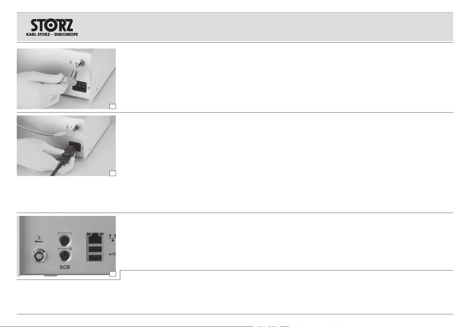
Aufstellen und
Bedienungshinweise
Installation and
operating instructions
Montaje e
instrucciones operativas
WARNUNG: Das Gerät ist mit einer
Steckvorrichtung für den Potentialausgleich
3
ausgerüstet. Führen Sie den
Potentialausgleich nach Maßgabe der
national gültigen Vorschriften durch.
2. Das Potentialausgleichskabel an die
Steckvorrichtung für den Potentialausgleich {
anschließen.
3. Lassen Sie die Erdung ggf. durch sachkundiges
Personal durchführen (Abb. 6).
6
WARNUNG: Nur das von KARLSTORZ
gelieferte Netzkabel oder ein entsprechen-
3
des, mit nationalem Prüfzeichen
ausgestattetes Netzkabel verwenden.
Netzkabel anschließen, Netzstecker bis zum
Anschlag in Netzbuchse P einschieben (Abb. 7).
WARNUNG: Gerät nur mit der auf dem
Typenschild angegebenen Netzspannung
3
betreiben.
WARNUNG: Netzstecker nur außerhalb
7
explosionsgefährdeter Bereiche mit der
3
Stromversorgung verbinden bzw. trennen.
WARNUNG: Das Gerät ist nur dann
zuverlässig geerdet, wenn es an einer
3
einwandfrei installierten SchutzkontaktSteckdose angeschlossen ist.
Gegebenenfalls Fußschalter oder Steuerkabel
UP 006 für Kombination mit UNIDRIVE® S III
ARTHRO oder Steuerkabel 20 7010 70 für
Kombination mit CALCUSON bzw. UNIDRIVE® S III
anschließen (Abb. 8).
WARNING: The device is equipped with
a connector for attaching a ground line.
3
Carry out potential equalization as per the
applicable national regulations.
2. Connect the potential equalization cable to the
potential equalization connector {.
3. Where necessary, have grounding performed by
qualified personnel (Fig.6).
WARNING: The device may only be
operated with the power cable delivered
3
by KARLSTORZ or a similar power cable
which has a national inspection seal.
Connect power cord and insert the pow er plug fully
into the power cord receptacle P (Fig. 7).
WARNING: Only operate the device with
the voltage stated on the manufacturer´s
3
identification plate.
WARNING:
power plug to/from the power supply outside
3
of areas subject to explosion hazards.
WARNING: Grounding reliability can only
be achieved when the device is connected
3
to a properly installed ‘Hospital only’ or
‘Hospital Grade’ receptacle (i.e. approved
for use in an operating room).
If necessary, connect the footswitch or control
cable UP 006 for combination with UNIDRIVE®
S III ARTHRO or control cable 20 7010 70 for
combination with CALCUSON or UNIDRIVE® S III
(Fig. 8).
Only connect/disconnect the
ADVERTENCIA: El equipo está provisto
de un enchufe para conexión equipotencial.
3
Efectúe la conexión equipotencial de
acuerdo con las normativas nacionales
vigentes.
2. Conecte el cable para conexión equipotencial
en el enchufe{ previsto al efecto.
3. Es recomendable que la conexión a tierra sea
efectuada por un técnico experto en la materia
(fig.6).
CUIDADO: Utilice únicamente el cable de
red suministrado por KARLSTORZ o uno
3
de calidad equivalente que lleve la marca
de homologación nacional.
Conecte el cable de red, e introduzca el enchufe de
red hasta el tope en el conector de red P (fig. 7).
CUIDADO: Conecte a la red solo
con la tensión indicada en la placa de
3
especifi caciones.
CUIDADO: Conecte/desconecte el enchufe
de la red de alimentación de corriente
3
únicamente en zonas que no estén
expuestas a riesgo de explosión.
CUIDADO: La conexión a tierra de
este aparato es únicamente fi able si se
3
encuentra conectado a un enchufe con
puesta a tierra debidamente instalado.
Si es necesario, conecte el interruptor de pedal o
el cable de mando UP 006 para la combinación
con la UNIDRIVE
mando 20 7010 70 para la combinación con el
CALCUSON / la UNIDRIVE® S III (fig. 8).
®
S III ARTHRO o el cable de
19
8
WARNUNG: Der ENDOMAT® SELECT
ist nicht dafür vorgesehen mit anderen
3
Geräten über die USB- oder EthernetSchnittstelle verbunden zu werden.
Diese Schnittstellen sind nur dem
KARLSTORZ Service vorbehalten.
WARNING: The ENDOMAT® SELECT is
not intended to be connected to other
3
equipment via the USB or Ethernet
interface. These interfaces are exclusively
reserved for KARL STORZ service.
CUIDADO: La ENDOMAT® SELECT
no está prevista para ser conectada
3
con otros aparatos mediante la interfaz
USB o Ethernet. Estas interfaces están
reservadas exclusivamente para el
Servicio Técnico de KARL STORZ.
Page 28
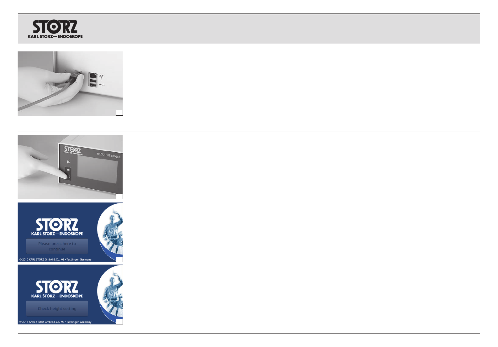
Aufstellen und
Bedienungshinweise
Installation and
operating instructions
Montaje e
instrucciones operativas
7. 4 KARLSTORZ-SCB
HINWEIS:
1
ziehen des SCB-Verbindungskabels zu ver hindern, besitzt der SCB-Stecker eine Schutzvorrichtung. Zum Ausstecken des SCB-Kabels
daher am Stecker ziehen, nicht am Kabel!
Das SCB-Kabel 20 0901 70 an eine der (gleichwertigen) SCB-Buchsen U auf der Rückseite des
Geräts anschließen (Abb. 9). Das andere Ende des
Kabels mit einem KARL STORZ-SCB Steuergerät
9
(KARL STORZ Communication Bus) oder wei teren
SCB-Geräten verbinden (siehe hierzu Gebrauchsanweisung KARL STORZ-SCB control NEO System).
Um ein versehentliches Heraus-
7. 5 Inbetriebnahme
Netzschalter Q einschalten (grüne Kontrollleuchte
leuchtet auf) (Abb. 10).
Das Gerät führt anschließend einen
Selbsttest durch, bei dem die verschiedenen
Systemkomponenten geprüft werden.
Fall a: nach Abschluss des Ladevorgangs erscheint
ein Startscreen mit der Schaltfläche »Please press
here to continue« (Abb. 11).
Fall b: nach Abschluss des Ladevorgangs
10
erscheint ein Startscreen mit der Schaltfläche
»Höheneinstellung überprüfen« (Abb. 12).
Im Fall b bestätigt der Anwender mit Betätigung
der Schaltfläche, dass die Position des Geräts
entsprechend der Einstellung der Höhendifferenz
ist (siehe Kapitel 7.15.1 Einstellungen –
Höhendifferenz).
HINWEIS: Mit der Bestätigung der Schaltflä-
1
che auf dem Startbildschirm (Abb. 11/12) ertönt ein akustisches Bereitschaftssignal, dass
11
12
zur Überprüfung des Alarmsystems dient.
WARNUNG: Aus Sicherheitsgründen darf
das Gerät nur verwendet werden, wenn un-
3
mittelbar nach Betätigung der Schaltfl äche
das Bereitschaftssignal zu hören war!
WARNUNG: Die Verwendung des
Advanced Softwarepakets bietet eine
3
Einstellung für Ausgleich des Höhenunterschieds zwischen dem Gerät und der Kavität. Diese Einstellung korrigiert die Druckmessung und -steuerung. Überprüfen Sie
die Einstellung nach dem Einschalten, um
unbeabsichtigten Überdruck zu vermeiden.
7. 4 KARLSTORZ-SCB
NOTE: To avoid mistakenly pulling out the
1
SCB connecting cable, the SCB connector
possesses a protection device. Therefore, to
unplug the SCB cable, pull out the connector
– do not pull directly on the cable!
Connect the SCB cable 20 0901 70 to an
(equivalent) SCB socket U on the back of the
device (Fig. 9). Connect the other end of the
cable to the KARL STORZ-SCB (KARL STORZ
Communication Bus) control device or other SCB
devices (see KARL STORZ-SCB control NEO
System Instruction Manual).
7. 5 Operating the device
Switch on the device at its power switch
(green indicator light illuminates) (Fig. 10).
The device will then conduct a self-test,
checking all system components for proper
operation.
Case A: Once charging is complete, a start screen
will appear, with the button: ‘Please press here to
continue’ (Fig. 11).
Case B: Once charging is complete, a start screen
will appear, with the button: ‘Check height setting’
(Fig. 12).
In Case B, the user presses the button to confirm
that the position of the device matches the height
difference setting (see Section 7.15.1 ‘Settings –
height difference’).
NOTE: When the button on the start screen is
1
pressed (Fig. 11/12), an acoustic ready signal
will sound in order to check the alarm system.
WARNING: For safety reasons, the device
may only ever be used if, immediately after
3
‘first click’, the acoustic availability signal
sounded!
WARNING: Using advanced software
package provides a setting for height
3
difference between the device and the
cavity. This setting corrects the pressure
measurement and control. Check the
setting after power on to avoid unintended
over pressure.
Q
7. 4 KARLSTORZ-SCB
NOTA: Con el fin de evitar extraer inadvertida-
1
mente el cable de conexión SCB, el enchufe
SCB está provisto de un dispositivo protector.
Para desconectar el cable SCB de la red, tire
por tanto del enchufe y no del cable.
Conecte el cable SCB 20 0901 70 a uno de los
conectores SCB U (equivalentes) de la parte posterior del aparato (fig. 9). Conecte el otro extremo del
cable con la unidad de control KARL STORZ-SCB
(KARL STORZ Communication Bus) o los otros aparatos SCB (véase para esto el Manual de instrucciones del sistema KARL STORZ-SCB control NEO).
7. 5 Puesta en marcha
Conecte el interruptor de red Q (ahora se ilumina la
lámpara piloto verde) (fig. 10).
A continuación, el aparato realiza un test
automático para la comprobación de los
diferentes componentes del sistema.
Caso a: Una vez finalizado el proceso de carga,
aparece una pantalla de inicio con el botón “Please
press here to continue” (Presione aquí para
continuar) (fig. 11).
Caso b: Una vez finalizado el proceso de carga,
aparece una pantalla de inicio con el botón “Check
height setting” (Comprobar ajuste de altura) (fig. 12).
En el caso b, el usuario presiona el botón para
confirmar que la posición del aparato corresponde
al ajuste de la diferencia de altura (véase el capítulo
7.15.1 Configuración – Diferencia de altura).
NOTA: Al presionarse el botón en la pantalla
1
de inicio (figs. 11/12) se emite una señal
acústica de estado dispuesto, que sirve para
comprobar el sistema de alarmas.
CUIDADO: Por razones de seguridad, el
aparato debe utilizarse únicamente si la
3
señal de estado dispuesto se ha emitido
inmediatamente después de presionarse
el botón.
CUIDADO: Al utilizar el paquete de software
“Advanced”, el usuario dispone de un ajuste
3
para compensar la diferencia de altura entre
el aparato y la cavidad. Este ajuste corrige
la medición y el control de la presión. Compruebe el ajuste después de la conexión a
fi n de evitar una sobrepresión involuntaria.
20
Page 29
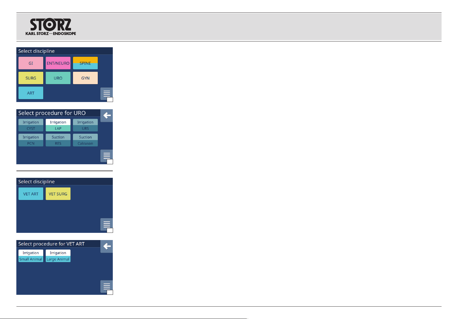
Aufstellen und
Bedienungshinweise
Installation and
operating instructions
Montaje e
instrucciones operativas
7. 6 Disziplin/Verfahren
7. 6. 1 Humanmedizin
Nach dem Aufstarten des Geräts erscheint der
Bildschirm zur Auswahl der Disziplin (Abb. 1).
Nach (beispielhaftem) Auswählen der Disziplin
URO erscheint der Bildschirm »Prozedur für
URO wählen« (Abb. 13).
7. 6. 2 Veterinärmedizin
1
Nach dem Aufstarten des Geräts erscheint der
Bildschirm zur Auswahl der Disziplin (Abb. 2).
Nach (beispielhaftem) Auswählen der Disziplin
VET ART erscheint der Bildschirm »Prozedur für
VET ART wählen« (Abb. 14).
HINWEIS: Wenn ein Schlauchset
1
ausgewählt wurde, welches nur die dann
hellen Prozeduren unterstützt, sind diese
13
»ausgegraut«.
Nach Wahl der gewünschten Prozedur wird
mittels einer Animation das Aufsetzen der
Schlauchkassette erklärt (siehe Abb. 15, Seite 22
oben).
7. 6 Discipline/procedure
7. 6. 1 Human medicine
After starting up the device, a screen is
displayed for the user to select the discipline
(Fig. 1).
After selecting the discipline URO, for example,
the screen ‘Select procedure for URO’ appears
(Fig. 13).
7. 6. 2 Veterinary medicine
After starting up the device, a screen is
displayed for the user to select the discipline
(Fig. 2).
After selecting the discipline VET ART, for
example, the screen ‘Select procedure for VET
ART’ appears (Fig. 14).
NOTE: If a tubing set was selected which then
1
only supports the light procedures, these are
grayed out.
Following selection of the desired procedure,
an animation explains how to insert the tubing
cartridge (see Fig.15, top of page22).
7. 6 Disciplina/procedimiento
7. 6. 1 Medicina humana
Una vez que el aparato haya arrancado, aparece
la pantalla de selección de la disciplina (fig. 1).
Al seleccionarse (por ejemplo) la disciplina URO,
aparece la pantalla “Seleccionar procedimiento
para URO” (fig. 13).
7. 6. 2 Medicina veterinaria
Una vez que el aparato haya arrancado, aparece
la pantalla de selección de la disciplina (fig. 2).
Al seleccionarse (por ejemplo) la disciplina
VET ART, aparece la pantalla “Seleccionar
procedimiento para VET ART” (fig. 14).
NOTA: Si se ha seleccionado un set de
1
tubos flexibles que entonces solo admite los
procedimientos claros, estos aparecerán de
color gris.
Una vez seleccionado el procedimiento que se
desee, se explica el montaje del cartucho de tubos
flexibles mediante una animación (véase la fig. 15,
pág. 22 arriba).
21
2
14
Page 30

Aufstellen und
Bedienungshinweise
Installation and
operating instructions
Montaje e
instrucciones operativas
7. 7 Aufsetzen der
Schlauchkassette
VORSICHT: Nur die für den ENDOMAT®
SELECT vorgesehenen Schlauchkassetten
2
bzw. Schlauchsets verwenden.
Stimmen die aufgesetzte Kassette und die
gewählte Prozedur nicht überein, wird eine
entsprechende Meldung eingeblendet (Abb. 16).
7. 7. 1 Erstmaliges Aufsetzen der
15
16
17
Schlauchkassette/Aufstarten
siehe Kapitel 7.6.
7. 7. 2 2. und folgende Aufsetzen der
Schlauchkassette
Es erscheint die zuletzt gewählte Prozedur.
Wird nun die passende Kassette aufgesetzt, erfolgt
der Wechsel ins Betriebsmenü. Wenn ein Wechsel
gewünscht ist, gelangt man durch Drücken des
Buttons zurück zur Fachbereichsauswahl.
Stimmen die aufgesetzte Kassette und
die gewählte Prozedur überein, erfolgt (bei
geschlossenem Pum penhebel) der Wechsel in
die entsprechende Arbeitsebene.
Schlauchkassette für Einmalgebrauch
WARNUNG: Überprüfen Sie vor der
Verwendung das Verfalldatum sowie
3
die Verpackung auf Beschädigungen.
Produkte mit abgelaufenem Verfalldatum
bzw. beschädigte Verpackungen dürfen
nicht verwendet werden.
WARNUNG: Einweg-Kassetten und
-Schläuche sind für den einmaligen
3
Gebrauch bestimmt und dürfen nicht
erneut sterilisiert werden. Nach Gebrauch
entsorgen.
Schlauchkassette aufsetzen und Hebel gegen den
Uhrzeigersinn drehen (Abb. 17, 18).
7. 7 Inserting the tubing cartridge
CAUTION: Only use the tubing cartridges
or tubing sets designed for the ENDOMAT®
2
SELECT.
If the inserted cartridge and selected procedure
do not match, a corresponding message is
displayed (Fig. 16).
7. 7. 1 Inserting the tubing cartridge for
the first time/startup
see section 7.6.
7. 7. 2 Inserting the tubing cartridge for the
second and subsequent times
The procedure last selected appears.
If the matching cartridge is now inserted, the user
is taken to the operating menu. Should you wish to
change, press the button to return to the medical
specialization selection.
If the inserted cartridge and selected procedure
match, the user is taken to the appropriate
working level (if the pump lever is closed).
Disposable tubing cartridge
WARNING: Check the expiration date and
the package for possible damage prior to
3
use. Products past expiration date or with
damaged packaging must not be used.
WARNING: Disposable cartridges and
tubes are intended for single use and must
3
not be resterilized. Discard after use.
Insert the tubing cartridge and turn the lever
counterclockwise (Fig. 17, 18).
7. 7 Montaje del cartucho de tubos
fl exibles
ADVERTENCIA: Utilice solamente
los cartuchos/ sets de tubos fl exibles
2
previstos para la ENDOMAT® SELECT.
Si el cartucho insertado y el procedimiento
seleccionado no son compatibles entre sí, se
muestra el mensaje correspondiente (fig. 16).
7. 7. 1 Montaje del cartucho de tubos fl exibles
por primera vez/ arranque
Véase el capítulo 7.6.
7. 7. 2 Montaje del cartucho de tubos fl exibles
por segunda vez y siguientes
Aparece el procedimiento que se haya
seleccionado la última vez.
Si ahora se inserta el cartucho apropiado, el
sistema pasa a mostrarle el menú de servicio. Si
desea cambiar, presione el botón para volver a la
selección de la especialidad.
Si el cartucho insertado y el procedimiento
seleccionado son compatibles entre sí, el
sistema (estando la palanca de bomba cerrada)
pasa al nivel de trabajo que corresponda.
Cartucho de tubos flexibles desechable
CUIDADO: Antes de su utilización,
compruebe la fecha de caducidad y
3
asegúrese de que el embalaje no presente
deterioros. No se deben utilizar productos
con fecha de caducidad vencida o
embalajes deteriorados.
CUIDADO: Los cartuchos y tubos
fl exibles desechables están previstos para
3
utilizarse una sola vez y no deben volver
a esterilizarse. Deséchelos después de
haberlos usado.
Monte el cartucho de tubos flexibles y gire la
palanca en el sentido contrario al de las agujas del
reloj (figs. 17, 18).
22
18
HINWEIS: Es gibt optional erhältliche,
1
wiederverwendbare Schlauchkassetten. Die zu
den wiederverwendbaren Schlauchkassetten
mitgelieferte Gebrauchsanweisung beachten.
NOTE: Reusable tubing cartridges are also
1
available. The instruction manual supplied
with the reusable tubing cartridges must be
observed.
NOTA: Están disponibles de forma opcional
1
cartuchos reutilizables de tubos flexibles.
Observe los Manuales de instrucciones
suministrados junto con los cartuchos
reutilizables de tubos flexibles.
Page 31

Aufstellen und
Bedienungshinweise
Installation and
operating instructions
Montaje e
instrucciones operativas
❶
Die entsprechenden Schlauchenden mit dem
Spülflüssigkeitsbeutel (Einstichdorn) bzw. mit
dem Spülanschluss am Instrument (LUER-Lock)
verbinden (Abb. 19).
19
Die vorgewählte Prozedur (in diesem Fall
»Uretero-Renoskopie« ❶) wird im Touch-Display
angezeigt (Abb. 20).
20
7. 8 Entfernen der
Schlauchkassette
Den Hebel im Uhrzeigersinn bis zur 9-Uhr-Stellung
drehen und die Schlauchkassette abnehmen
(Abb. 21).
Connect the correct end of the length of tubing
to the irrigation-liquid bag (puncture needle) or to
the irrigation port on the instrument (LUER-Lock)
(Fig. 19).
The preselected procedure (in this case
“Ureterorenoscopy” ❶) is shown on the touch
display (Fig. 20).
7. 8 Removing the tubing
cartridge
Turn the lever clockwise to the 9 o'clock position
and remove the tubing cartridge (Fig. 21).
Conecte el extremo correspondiente del tubo
flexible con la bolsa de líquido de irrigación (mandril
de punción) e inserte el otro extremo en la conexión
de irrigación del instrumento (cierre LUER) (véase
la fig. 19).
La pantalla táctil muestra el procedimiento
preseleccionado (en este caso,
«ureterorrenoscopia» ❶) (fig. 20).
7. 8 Extracción del cartucho de
tubos fl exibles
Gire la palanca en el sentido de las agujas del reloj
hasta alcanzar la posición de las 9 horas y extraiga
el cartucho de tubos flexibles (fig. 21).
23
21
Page 32

Aufstellen und
Bedienungshinweise
Installation and
operating instructions
Montaje e
instrucciones operativas
7. 9 Schlauchkassette für
Absaugung anschließen
ENDOMAT® SELECT als Saugpumpe betreiben
(IBS®/RES/CALCUSON)
Variante A – indirekte Absaugung
(Absaugung für CALCUSON)
Wenn sich feste Bestandteile in der abgesaugten
Flüssigkeit befinden z. B. Steinkonkremente
(Urologie), so besteht ein gewisses Risiko der
Perforation des Pumpen kopfschlauches. Hier ist
22
es angebracht eine Saugflasche (siehe Zubehör)
zwischen Sauginstrument und ENDOMAT
SELECT zu schalten (Abb. 22). Für die indirekte
Absaugung das Einmal-Schlauchset 031647-10
verwenden.
VORSICHT: Wenn sich feste Bestandteile
in der abgesaugten Flüssigkeit befinden,
2
kann der Pumpenkopfschlauch perforiert
und der ENDOMAT ® SELECT kontaminiert
werden.
HINWEIS: Durch Füllen der Saugflasche mit
1
Wasser wird das Luftvolumen der Saugflasche
verkleinert. Dies hat erstens den Vorteil, dass
beim Starten der Absaugung am ENDOMAT ®
SELECT Flüssigkeit schneller angesaugt
wird (kleineres Totvolumen). Zweitens wird
praktisch keine Flüssigkeit nachgesaugt, wenn
die Absaugung am ENDOMAT ® SELECT
gestoppt wird.
7. 9 Connecting the tubing
cartridge for suction
Using the ENDOMAT® SELECT as a suction
pump (IBS®/RES/CALCUSON)
WARNING: Use of the KARLSTORZ
pump together with a KARLSTORZ
3
morcellator or shaver is not approved
for use in the United States.
Alternative A – indirect suction
(suction for CALCUSON)
®
When there are solid components in the suctioned
liquid such as stone concretions (urology), there
is a risk of perforating the pump head tubing. In
this case, it is recommended to connect a suction
bottle (see accessories) between the suction
instrument and the ENDOMAT
Use disposable turbing set 031647-10 for indirect
suction.
CAUTION: When there are solid
components in the suctioned liquid, the
2
pump head tubing can be perforated
and the ENDOMAT® SELECT can be
contaminated.
NOTE: When the suction bottle is filled with
1
water, the air volume of the suction bottle is
reduced. One advantage of this is that the
liquid is suctioned faster on starting suction
on the ENDOMAT® SELECT (smaller dead
volume). A second advantage is that almost
no fluid will be suctioned after the suction on
the ENDOMAT® SELECT has been stopped.
®
SELECT (Fig. 22).
7. 9 Conexión del cartucho de
tubos fl exibles para succión
Empleo de la ENDOMAT® SELECT como
bomba de succión (IBS®/RES/CALCUSON)
Variante A – Succión indirecta
(succión para CALCUSON)
Si en el líquido succionado se encuentran
componentes sólidos como, p. ej., cálculos
(urología), existe cierto riesgo de perforación del
tubo flexible del cabezal de la bomba. En este caso
es recomendable conectar una botella de succión
(véanse los accesorios) entre el instrumento de
succión y la ENDOMAT
set de tubos flexibles desechable 031647-10 para
la succión indirecta.
ADVERTENCIA: Si en el líquido
succionado se encuentran componentes
2
sólidos, el tubo fl exible del cabezal de la
bomba puede perforarse y la ENDOMAT ®
SELECT puede resultar contaminada.
NOTA: Al llenarse de agua la botella de
1
succión, se reduce el volumen de aire de
dicha botella. En primer lugar, ello conlleva la
ventaja de que, al arrancar la succión en la
ENDOMAT ® SELECT, el líquido se succiona
más rápidamente (menor volumen muerto). En
segundo lugar, no se succiona prácticamente
líquido alguno después de detenerse la
succión en la ENDOMAT ® SELECT.
®
SELECT (fig. 22). Utilice el
24
Page 33

Aufstellen und
Bedienungshinweise
Installation and
operating instructions
Montaje e
instrucciones operativas
1. Den Zulaufschlauch an der Schlauchkassette
(Schlauch oben; siehe Pfeil, Abb. 23) mit
Schlauchkonnektor auf den Anschluss am
Verschlussdeckel stecken, an dem sich das
Sieb befindet (Abb. 24).
2. D
en Ablaufschlauch an der Schlauchkassette
(Schlauch unten) in einen Auffangbehälter
hängen (Abb.27).
3. Das blaue Schlauchende des 2. Schlauchs des
Schlauchsets (ohne Kassette) auf das noch freie
23
2524
Flaschenanschlussrohr stecken (Abb.25).
4. Das orangefarbene Schlauchende mit dem
Instrument verbinden.
HINWEIS: Die Saugflasche muss auf
1
Patientenhöhe platziert werden, um zu
verhindern, dass aufgrund des Höhengefälles
zwischen Patient und Absaugflasche die
Saugflasche vollläuft.
Variante B – direkte Absaugung
®
(bei IBS
Für die direkte Absaugung das Einmal-Schlauchset
030647-10 verwenden (siehe Abb. 26).
1. Den Zulaufschlauch (orange gekennzeichnet
2. Den Ablaufschlauch (blau gekennzeichnet
und RES)
– siehe Abb. 26) mit dem Anschluss am
Instrument verbinden.
– siehe Abb. 27) mit dem Auffangbehälter
verbinden.
1. Attach the inflow tube on the tubing cartridge
(tube on top; see arrow, Fig. 23) with tube
connector onto the connector on the cap where
the wire tray is located (Fig. 24).
2. Place the outflow tube on the tubing cartridge
(tube at bottom) into a collection container
(Fig.27).
3. Attach the blue end of the 2nd tube in the
tube set (without cartridge) onto the free bottle
connection tube (Fig.25).
4. Connect the orange end of the tube to the
instrument.
NOTE: The suction bottle must be placed
1
at the height of the patient to prevent it from
filling up due to the height difference between
the patient and the suction bottle.
Alternative B – direct suction
®
(IBS
and RES)
Use the disposable turbing set 030647-10 for direct
suction (see Fig. 26).
1. Connect the inflow tube (marked orange, see
Fig. 26) with the connector on the instrument.
2. Connect the outflow tube (marked blue,
see Fig. 27) to the collection container.
1. Inserte un extremo del tubo flexible de entrada al
cartucho de tubos flexibles (tubo flexible, arriba;
véase la flecha, fig. 23) con conector para tubo
flexible en la conexión de la tapa de cierre en la que
se encuentra el cesto (fig. 24).
2. Conecte el tubo flexible de salida del cartucho de
tubos flexibles (tubo flexible, abajo) en un recipiente
colector (fig. 27).
3. Inserte el extremo azul del segundo tubo flexible
(sin cartucho) en el tubo de conexión de botella que
queda libre (fig. 25).
4. Conecte el extremo de color naranja del tubo
flexible con el instrumento.
NOTA: La botella de succión ha de
1
posicionarse a la altura del paciente, a fin
de evitar que se llene del todo debido a la
diferencia de altura entre el paciente y la
botella de succión.
Variante B – Succión directa
(con IBS
Utilice para la succión directa el set de tubos
flexibles desechable 030647-10 (véase la fig. 26).
1. Conecte el tubo flexible de entrada (identificado
2. Conecte el tubo flexible de salida (identificado
®
y RES)
de color naranja– véase la fig. 26) con la
conexión del instrumento.
de color azul– véase la fig. 27) con el recipiente
colector.
25
26
27
Page 34

Aufstellen und
Bedienungshinweise
Installation and
operating instructions
Montaje e
instrucciones operativas
❶
❷
❹
❸ ❸
❽ ❺
7. 10 ENDOMAT® SELECT als
Spülpumpe einsetzen
Je nach Einsatzgebiet (durch die Schlauchkassette
vorgegeben) kann entweder der Spülfl uss oder
der Spüldruck frei gewählt werden. Für den jeweils
anderen Parameter (Druck bzw. Fluss) kann eine
3-stufi ge Begrenzung festgelegt werden.*
*HINWEIS: Sind auf Ihrem System
28
1
einige Einstellparameter nicht sichtbar, ist
möglicherweise das »Advanced«-Paket nicht
freigeschaltet.
7. 10. 1 Spülfluss vorgeben
(SURG, GI, VET SURG)
Im Anzeigefeld ❹ wird der Soll-Wert (digitaler Zahlenwert mit orangefarbenen Begrenzungsmarkierungen) und der Ist-Wert (weiße Balkenanzeige) für den
Spülfl uss (in ml/min) angezeigt (Abb. 28).
Mit installiertem Advanced Paket wird im Anzeigefeld
❽
angezeigt.
Mit dem dazugehörigen Start/Stopp-Button
die Rollenpumpe aktiviert und deaktiviert.
Fluss einstellen: Über die ±Buttons
Sollwert in 100 ml/min-Schritten einstellen.
Dies ist unabhängig vom Pumpenstatus.
SURG: 100…2 500 ml/min
VET SURG: 100 ... 3 500 ml/min
GI: 100…1 000 ml/min
Druckbegrenzung einstellen (Voraussetzung:
installiertes Advanced Softwarepaket oder
VET Softwarepaket): Über die Taste왘 die Druck-
begrenzung einstellen (Bereich 100mmHg -->
300mmHg --> 500mmHg --> 100mmHg...).
die Begrenzung des Drucks (in mmHg)
(ADVANCED: 100...3 500 ml/min)
HINWEIS: Der Standardwert der
1
Druckbegrenzung ohne installiertes
»Advanced«-Paket beträgt 500 mmHg.
❸
den
❺
7. 10 Using the ENDOMAT® SELECT
as an irrigation pump
Depending on the fi eld of application (determined
by the tubing cartridge), either the irrigation fl ow or
irrigation pressure can be freely selected. For the
other parameters (pressure or fl ow), a 3-level limita-
tion can be specifi ed.*
*NOTE: If some setting parameters are not
1
visible on your system, it is possible that the
‘Advanced’ package has not been enabled.
7. 10. 1 Specifying the irrigation flow
(SURG,GI,
In the display fi eld ❹ the setpoint (digital numerical
value with orange limitation triangles) and the actual
value (white bar display) are shown for the irrigation
fl ow (in ml/min) (Fig.28).
If the Advanced package is installed, the limitation
of pressure (in mmHg) is shown in display fi eld
The roller pump is activated and deactivated with
the associated Start/Stop button
wird
Setting the fl ow: Set the setpoint in 100 ml/min
increments using the ±buttons
This is not affected by the pump status.
SURG: 100…2,500 ml/min
(ADVANCED: 100...3,500 ml/min)
VET SURG: 100…3,500 ml/min
GI: 100…1 000 ml/min
Set the pressure limit (prerequisite: installed
Advanced software package or VET software
package): Set the pressure limitation using the
button왘 (range 100mmHg --> 300mmHg -->
500mmHg --> 100mmHg...).
NOTE: If the Advanced package is not
1
installed, the default value for pressure
limitation is 500 mmHg.
VET SURG
)
❸
7. 10 Empleo de la ENDOMAT® SELECT comobombadeirrigación
En función del campo de aplicación (determinado
por el cartucho de tubos fl exibles), puede seleccio-
narse libremente el fl ujo de irrigación o la presión
de irrigación. Para el otro parámetro (presión o
fl ujo, según el caso) puede defi nirse un límite de
3niveles.*
*NOTA: Si algunos parámetros de ajuste
1
no son visibles en su sistema, ello puede
deberse a que no está habilitado el paquete
“Advanced”.
7. 10. 1 Especifi cación del fl ujo de irrigación
(SURG, GI, VET SURG)
En el campo indicador❹ aparecen representados el valor nominal (valor numérico digital con
marcas de limitación de color naranja) y el valor real
(indicador de barra blanca) del fl ujo de irrigación
(enml/ min) (fi g. 28).
Si está instalado el paquete “Advanced”, el límite
❽
.
de presión (en mmHg) aparece representado en el
❺
.
.
campo indicador
La bomba de rodillos se activa y desactiva con el
botón de inicio/parada
Ajuste del fl ujo: Ajuste el valor nominal en incre-
mentos de 100 ml/min usando los botones±
Esto es independiente del estado de la bomba.
SURG: 100…2 500ml/min
(ADVANCED: 100...3 500 ml/min)
VET SURG: 100 ... 3 500 ml/min
GI: 100…1 000ml/min
Ajuste del límite de presión (requisito previo:
paquete de software “Advanced” o paquete
de software VET instalado): Ajuste el límite de
presión con la tecla왘 (margen: 100mmHg -->
300mmHg --> 500mmHg --> 100mmHg...).
NOTA: Si el paquete “Advanced” no está
1
instalado, el valor predeterminado del límite de
presión es 500 mmHg.
❽
.
❺
correspondiente.
❸
.
26
Page 35

Aufstellen und
Bedienungshinweise
Installation and
operating instructions
Montaje e
instrucciones operativas
❶
❷
❹
❸ ❸
➏
7. 10. 2 Spülfluss vorgeben (ENT/NEURO)
In Verbindung mit Spülschäften dient diese Rollenpumpe mit der Prozedur CLEARVISION
gung des distalen Objektivs (Endoskopfenster). Für
die Dauer der Aktivierung durch den Fußschalter
(siehe Zubehör) spült die Pumpe Flüssigkeit über
das distale Objektiv. Durch ein fortwährendes Oszillieren des Pumpenkopfs werden Flüssigkeitstropfen
vom Objektiv wieder zurückgezogen. Mit Loslassen
des Fußschalters wird ein angefangener Zyklus
vollständig beendet und dadurch noch Flüssigkeit in
29
den Schaft gesaugt.
Im Anzeigefeld
lenwert mit orangefarbenen Begrenzungsmarkierungen) und der Ist-Wert (weiße Balkenanzeige) für den
Spülfl uss (in ml/min) angezeigt (Abb. 29).
Mit dem dazugehörigen Fußschalter
Rollenpumpe aktiviert und deaktiviert.
Fluss einstellen: Über die ±Buttons
Sollwert in folgenden Schritten einstellen.
Dies ist unabhängig vom Pumpenstatus.
ENT/NEURO
❹
wird der Soll-Wert (digitaler Zah-
: 50 – 65 – 80 – 95 – 110 – 130ml/ min
®
der Reini-
➏
wird die
❸
den
7. 10. 2 Specifying the irrigation flow
(ENT/NEURO)
In combination with irrigation sheaths, this roller
pump is used to clean the distal lens (endoscope
window) during the CLEARVISION
pump delivers liquid via the distal lens for as long as
it is activated by the footswitch (see Accessories).
The continual oscillation of the pump head removes
drops of liquid from the lens. When the footswitch is
released, an ongoing cycle will be fully completed,
meaning that liquid will still be suctioned into the
sheath.
The display field
figure with orange limit markings) and the actual
value (white bar display) for the irrigation flow
(in ml/ min) (Fig. 29).
The roller pump is activated and deactivated by the
associated footswitch ".
Setting the flow: Adjust the target value in the
following steps using the ± buttons ".
This is not dependent on the pump status.
ENT/NEURO: 50 – 65 – 80 – 95 – 110 – 130 ml/ min
❹
shows the target value (digital
®
procedure. The
7. 10. 2 Especificación del flujo de irrigación
(ENT/NEURO)
Esta bomba de rodillos, en combinación con vainas
de irrigación, sirve para la limpieza del objetivo
distal (mirilla del endoscopio) con el procedimiento
CLEARVISION
rruptor de pedal (véase Accesorios), la bomba irriga
líquido por el objetivo distal. Las gotas de líquido
se retiran del objetivo mediante una oscilación
continua del cabezal de la bomba. Al soltarse el interruptor de pedal, se fi naliza por completo un ciclo
comenzado y, de este modo, todavía se succiona
líquido hacia la vaina.
En el campo indicador ❹ aparecen representados el valor nominal (valor numérico digital con
marcas de limitación de color naranja) y el valor real
(indicador de barra blanca) del fl ujo de irrigación
(enml/ min) (fi g. 29).
La bomba de rodillos se activa y desactiva con el
correspondiente interruptor de pedal ➏.
Ajuste del fl ujo: Ajuste el valor nominal en incre-
mentos sucesivos con los botones ± ➌.
Esto es independiente del estado de la bomba.
ENT/NEURO: 50 – 65 – 80 – 95 – 110 – 130 ml/ min
®
. Mientras esté activada con el inte-
27
Page 36

Aufstellen und
Bedienungshinweise
Installation and
operating instructions
Montaje e
instrucciones operativas
❸
❸
❸
❼
❼
❼
❸
❹
❹
❹
❼
❶
❶
❶
❶
❹
❷
❷
❽
❽
❽
❷
❸
❸
❸
❸
❷
❺
❻
❺
❺
7. 10. 3 Spüldruck vorgeben
(HYS, URO, ART, SPINE, VET ART)
WARNUNG: Starten Sie immer mit
dem niedrigstmöglichen Druck, um die
3
gewünschte Distension zu erreichen.
Erhöhen Sie den Distensionsdruck, bis ein
klares flüssiges Medium erhalten wird.
Im Anzeigefeld ❹ wird der Soll-Wert (digitaler
Zahlenwert mit orangefarbenen Markierungen)
und der Ist-Wert (weiße Balkenanzeige) für den
Spüldruck (in mmHg) angezeigt.
30
URO/ART/VET ART: Im Anzeigefeld ❼ wird die
prozentuale Druck erhöhung (Boostmodus) (in %)
angezeigt (Abb. 30).
URO/GYN: Im Anzeigefeld ❹ ist eine
Sicherheitsschwelle bei 100 mmHg durch einen
weißen vertikalen Strich sowie ein »gesperrtes«
Schloss zu erkennen). Um Werte zwischen
100 mmHg und 150 mmHg einstellen zu können,
muss die + Taste ❸ solange berührt werden,
bis sich das Schloss vollständig gefüllt hat und
»geöffnet« ist (Abb. 31).
Advanced Softwarepaket oder VET
31
Softwarepaket installiert (Abb. 32, 33):
Im Anzeigefeld ❽ wird die Begrenzung des Flusses
(in ml/min) angezeigt.
Mit dem dazugehörigen Start/Stopp-Button ❺ oder
Fußschalter-Button ❻
und deaktiviert.
Druck einstellen:
den Sollwert in 10 mmHg-Schritten einstellen ( Bereich 20…150 mmHg). Der Bereich
20…150 mmHg gilt für alle Druckgeregelten Prozeduren außer VET ART »Large Animal«, in der ein maximaler Druck von 400 mmHg einstellbar ist (Abb. 33).
32
Dies ist unabhängig vom Pumpenstatus.
Boost: Über die Taste 왘 die prozentuale
(kurzzeitige*) Druckerhöhung einstellen (Bereich
10 % – 20 % – 30 % – 40 % – 50 % -> 10 %...).
*HINWEIS: Der Boost-Nachlauf beträgt 2 s.
1
Bei installiertem Advanced Softwarepaket kann
der Nachlauf auf bis zu 60 s verlängert werden.
HINWEIS: In der Kombination des ENDOMAT ®
1
Select mit dem UNIDRIVE ® S III über das
Steuerkabel UP 006 wird der Boost aktiviert,
sobald die Shaverfunktion aktiviert wird.
33
wird die Rollenpumpe aktiviert
Über die ± Buttons ❸
7. 10. 3 Specifying the irrigation pressure
(HYS, URO, ART, SPINE, VET ART)
WARNUNG: Always start with the lowest
possible pressure needed to achieve the
3
desired distension. Increase the distension
pressure until there is a clear, liquid
medium.
In the display field ❹ the setpoint (digital numerical
value with orange limitation marks) and the actual
value (white bar display) are shown for the irrigation
pressure (in mmHg).
URO/ART/VET ART: In the display field ❼, the
pressure increase (Boost mode) (in %) is shown
(Fig. 30).
URO/GYN: In the display field ❹, the safety
threshold at 100 mmHg can be seen by means of
a vertical white line and a ‘locked’ padlock symbol.
In order to set values between 100 mmHg and 150
mmHg, the + button ❸ will need to be pressed until
the padlock symbol has completely filled up and is
shown as ‘opened’ (Fig. 31).
Advanced software package or VET software
package installed (Fig. 32, 33):
In the display field ❽, flow limitation is shown
(in ml/ min).
The roller pump is activated and deactivated with
the associated Start/Stop button
button ❻.
Setting the pressure: Set the setpoint in
increments of 10 mmHg using the ± buttons ❸
(range 20…150 mmHg). The range of
20…150 mmHg applies for all pressure-regulated
procedures apart from VET ART ‘Large Animal’, for
which a maximum pressure of 400 mmHg can be
set (Fig. 33).
This is not affected by the pump status.
Boost: Using the button 왘, set the (brief*) increase
in pressure as a percentage (range 10% – 20% –
30% – 40% – 50% -> 10%...).
*NOTE: The Boost run-on is 2 seconds. If the
1
Advanced software package is installed, the
run-on can be extended by up to 60 seconds.
NOTE: When the
1
used in combination with the
via control cable UP 006, the Boost function
is activated as soon as the Shaver function is
activated.
ENDOMAT ®
❺
or footswitch
Select is being
UNIDRIVE ®
S III
7. 10. 3 Especifi cación de la presión de irriga-
ción (HYS, URO, ART, SPINE, VET ART)
CUIDADO: Comience siempre con la
presión más baja posible para obtener la
3
distensión deseada. Prosiga aumentando
la presión de distensión hasta obtener un
medio líquido claro.
En el campo indicador ❹
valor nominal (valor numérico digital con marcas de limitación de color naranja) y el valor real (indicador de
barra blanca) de la presión de irrigación (en mmHg).
URO/ART/VET ART: En el campo indicador ❼
aparece representado el aumento de presión (modo
de refuerzo) (expresado en %) (fig. 30).
URO/GYN: In the display field ❹, the safety
threshold at 100 mmHg can be seen by means of
a vertical white line and a ‘locked’ padlock symbol.
In order to set values between 100 mmHg and
150 mmHg, the + button ❸ will need to be pressed
until the padlock symbol has completely filled up
and is shown as ‘opened’ (Fig. 31).
Paquete de software “Advanced” o paquete de
software VET instalado (figs. 32, 33):
En el campo indicador ❽ aparece representado el
límite de flujo (en ml/min).
La bomba de rodillos se activa y desactiva con el
correspondiente botón de inicio/parada ❺ o
del interruptor de pedal ❻.
Ajuste de la presión: Ajuste el valor nominal en
incrementos de 10 mmHg usando los botones ± ❸
(margen: 20…150 mmHg). El margen de ajuste
20…150 mmHg es válido para todos los procedimientos regulados por presión excepto VET ART
“Large Animal” (Animal grande), en el cual puede
ajustarse una presión máxima de 400 mmHg (fig. 33).
Esto es independiente del estado de la bomba.
Refuerzo: Ajuste el aumento (breve*) de presión
expresado en % usando la tecla 왘 (margen: 10% –
20% – 30% – 40% – 50% -> 10%...).
*NOTA: La respuesta de refuerzo dura 2 s.
1
Si el paquete de software “Advanced” está
instalado, la respuesta de refuerzo puede
prolongarse hasta los 60 s.
NOTA: Al utilizar el
1
combinación con el
el cable de mando UP 006, el refuerzo se
activa en cuanto se activa la función del shaver.
aparecen representados el
botón
ENDOMAT ® Select en
UNIDRIVE ® S III mediante
28
Page 37

Aufstellen und
Bedienungshinweise
Installation and
operating instructions
Montaje e
instrucciones operativas
❸
❸
❼
❹
❸
❹
❶
❶
❹
❶
❽
❷
❷
❽
❸
❷
❸
❸
➎
➎
Flussbegrenzung einstellen ❽ (
installiertes Advanced Softwarepaket oder
VET ART Softwarepaket
Über die Taste 왘 die Flussbegrenzung einstellen
(Abb. 34).
HYS, URO, SPINE: 200 ml/min – 400 ml/ min –
600 ml/min --> 200 ml/ min...
ART, VET ART: 1 500 ml/min – 2 000 ml/min –
2 500 ml/min --> 1 500 ml/ min...
HINWEIS: Der Standardwert der
34
35
1
Flussbegrenzung beträgt ohne installiertes
»Advanced«-Paket 400 ml/min (HYS & URO),
200 ml/min (SPINE) bzw. 1 500 ml/min (ART).
7. 10. 4 Spülpumpe starten
Bei aktivierter Spülpumpe zeigt der weiße Balken
im Anzeigefeld ❹ den Ist-Wert des Spülflusses
(siehe Abb. 35) bzw. den Ist-Wert des Spüldrucks
(siehe Abb. 36). Der aktuelle Sollwert wird über
zwei orangefarbene Dreiecke in der Balkenanzeige
dargestellt. Die Balkenanzeige spiegelt den
gesamten Einstellbereich wider.
HINWEIS:
1
nach Ausschalten des Geräts gespeichert.
Eingegebene Sollwerte blei ben auch
Voraussetzung:
):
Set the flow limit ❽ (prerequisite: installed
Advanced software package or VET ART
software package):
Set the flow limitation using the button 왘 (Fig. 34).
HYS, URO, SPINE: 200 ml/min – 400 ml/ min –
600 ml/min --> 200 ml/ min...
ART, VET ART: 1,500 ml/min – 2,000 ml/min –
2,500 ml/min --> 1,500 ml/ min...
NOTE: If the Advanced package is not
1
installed, the default values for flow limitation
are: 400 ml/min (HYS & URO), 200 ml/min
(SPINE) and 1,500 ml/min (ART).
7. 10. 4 Starting the irrigation pump
If the irrigation pump is activated, the white bar in
the display field ❹ shows the actual value of the
irrigation flow (see Fig. 35) or the actual value of the
irrigation pressure (see Fig. 36). The current setpoint
value is indicated by two orange triangles in the bar
display. The bar display reflects the entire setting
range.
NOTE:
The settings are retained in the device’s
1
memory after the device is switched off.
Ajuste del límite de flujo ❽ (requisito previo:
paquete de software “Advanced” o paquete de
software VET ART instalado):
Ajuste el límite de flujo usando la tecla 왘 (fig. 34).
HYS, URO, SPINE: 200 ml/min – 400 ml/ min –
600 ml/min --> 200 ml/ min...
ART , VET ART: 1 500 ml/min – 2 000 ml/min –
2 500 ml/min --> 1 500 ml/ min...
NOTA: Si el paquete “Advanced” no está
1
instalado, el valor predeterminado del límite de
flujo es 400 ml/min (HYS y URO), 200 ml/min
(SPINE) o 1 500 ml/min (ART).
7. 10. 4 Inicio de la bomba de irrigación
Estando activada la bomba de irrigación, la barra
blanca representada en el campo indicador ❹
muestra el valor real del flujo de irrigación (véase
la fig. 35) / el valor real de la presión de irrigación
(véase la fig. 36). El valor nominal actual se indica
mediante dos triángulos de color naranja en el
indicador de barra. El indicador de barra refleja el
margen de ajuste completo.
NOTA:
1
Los valores nominales introducidos
permanecen guardados incluso después de
desconectarse el aparato.
29
❼
❽
➎
36
Page 38

Aufstellen und
Bedienungshinweise
Installation and
operating instructions
Montaje e
instrucciones operativas
❶
❹
❸ ❸
❹
❷
❻
❺
7. 11 ENDOMAT® SELECT als
Saugpumpe einsetzen
7. 11. 1 Saugfluss vorgeben
(IBS® Shaver, RES, CALCUSON
VETSURG)
Im Anzeigefeld
Zahlenwert mit orangefarbenen Markierungen)
und der Ist-Wert (weiße Balkenanzeige) für den
Saugfluss (in ml/min) angezeigt (siehe Abb. 37, 38).
Mit dem dazugehörigen Start/Stopp-Button ❺ oder
37
Fußschalter-Button ❻
und deaktiviert.
Fluss einstellen: Über die ± Buttons ❸
den Sollwert in 20 ml/min-Schritten (IBS®)
bzw. 100 ml/ min-Schritten (RES/CALCUSON)
einstellen.
Dies ist unabhängig vom Pumpenstatus.
®
IBS
Shaver: 100 ml/min – 300 ml/ min
RES, VET SURG Direct Suction:
100 ml/min – 1 000 ml/ min
CALCUSON, VET SURG Bottle Suction:
300 ml/min – 1 000 ml/ min
38
7. 11. 2 »Saugpumpe« starten
Bei aktivierter Pumpe zeigt der weiße Balken im
Anzeigefeld
(siehe Abb. 37, 38). Der aktuelle Sollwert wird
über zwei orangefarbene Markierungen in der
Balkenanzeige dargestellt. Die Balkenanzeige
spiegelt den gesamten Einstellbereich wider.
HINWEIS:
1
auch nach Ausschalten des Geräts gespeichert.
❹
wird der Soll-Wert (digitaler
wird die Rollenpumpe aktiviert
den Ist-Wert des Saugflusses
❹
Die eingegebenen Sollwerte bleiben
7. 11 Using the ENDOMAT® SELECT
as a suctionpump
7. 11. 1 Specifying the suction flow
(IBS® shaver, RES, CALCUSON
VETSURG)
WARNING: Use of the KARLSTORZ
pump together with a KARLSTORZ
3
morcellator or shaver is not approved
for use in the United States.
In the display field
value with orange limitation marks) and the actual
value (white bar display) are shown for the suction
flow (in ml/min) (Fig. 37, 38).
The roller pump is activated and deactivated with
the associated Start/Stop button
button ❻.
Setting the flow: Set the setpoint in 20 ml/min
increments (IBS
CALCUSON) using the ± buttons ❸.
This is not affected by the pump status.
®
IBS
shaver: 100 ml/min – 300 ml/ min
RES, VET SURG Direct Suction:
100 ml/min – 1,000 ml/ min
CALCUSON, VET SURG Bottle Suction:
300 ml/min – 1,000 ml/ min
7. 11. 2 Starting the suction pump
If the pump is activated, the white bar in the display
field
❹
shows the actual value of the suction flow
(see Fig. 37, 38). The current setpoint value is
indicated by two orange marks in the bar display.
The bar display reflects the entire setting range.
NOTE:
1
memory after the device is switched off.
❹
, the setpoint (digital numerical
❺
or footswitch
®
) or 100 ml/min increments (RES/
The settings are retained in the device’s
7. 11 Empleo de la ENDOMAT® SELECT comobombadesucción
7. 11. 1 Especifi cación del fl ujo de succión
(shaverIBS®, RES, CALCUSON
VETSURG)
En el campo indicador
el valor nominal (valor numérico digital con marcas
de limitación de color naranja) y el valor real
(indicador de barra blanca) del flujo de succión
(en ml/min) (véanse las figs. 37, 38).
La bomba de rodillos se activa y desactiva con el
correspondiente botón de inicio/parada ❺ o
del interruptor de pedal ❻.
Ajuste del flujo: Usando los botones ± ❸, ajuste
el valor nominal en incrementos de 20 ml/min (IBS®)
o 100 ml/ min (RES/CALCUSON).
Esto es independiente del estado de la bomba.
Shaver IBS
RES , VET SURG Direct Suction:
100 ml/min-1 000 ml/ min
CALCUSON, VET SURG Bottle Suction:
300 ml/min-1 000 ml/ min
7. 11. 2 Inicio de la “bomba de succión”
Estando activada la bomba, la barra blanca
representada en el campo indicador
valor real del flujo de succión (véanse las figs. 37,
38). El valor nominal actual se indica mediante dos
marcas de color naranja en el indicador de barra.
El indicador de barra refleja el margen de ajuste
completo.
®
: 100 ml/min-300 ml/ min
NOTA:
1
Los valores nominales introducidos
permanecen guardados incluso después de
desconectarse el aparato.
❹
aparecen representados
❹
muestra el
botón
30
Page 39

Aufstellen und
Bedienungshinweise
Installation and
operating instructions
Montaje e
instrucciones operativas
❶
❷
❹
❸ ❸
❹
➎
7. 12 Funktionsprüfung und EntlüftungdesSchlauchsystems
WARNUNG: Prüfen Sie dieses Gerät vor
jeder Anwendung auf seine Funktions-
3
fähigkeit.
HINWEIS: Auffanggefäß für austretende
1
Spülflüssigkeit bereithalten.
Den Start/Stopp-Button ❺ drücken und die Spülpumpe solange laufen lassen bis das Schlauchsystem komplett entlüftet (d. h. blasenfrei) ist.
SURG und GI
❹
Der an der Balkenanzeige
Wert muss mit der Sollwert-Vorgabe (siehe
orangefarbene Markierungen) übereinstimmen.
Sobald der Zuflusshahn am Instrument geschlossen
wurde, muss die Rollenpumpe die Förderung
39
einstellen.
HYS/URO/ART/SPINE
Zuflusshahn am Instrument langsam schließen.
Sobald der an der Balkenanzeige
Druckwert die Sollwert-Vorgabe (siehe
orangefarbene Markierungen) überschreitet, muss
die Rollenpumpe die Förderung einstellen.
angezeigte Spülfluss-
❹
angezeigte
7. 12 Test for proper operation and
air-relief of the tubing system
WARNING: Test this equipment prior to
each surgical procedure to ensure that it
3
functions correctly.
NOTE: Have a collecting container ready to
1
catch irrigation liquid as it runs out.
Press the Start/Stop button
pump run until all of the air has been released from
the tubing system (i.e. no bubbles).
SURG and GI
The irrigation flow rate indicated on the bar
❹
display
(see orange marks). As soon as the inflow valve on
the instrument is closed, the roller pump must stop
irrigation.
HYS/URO/ART/SPINE
Slowly close the inflow valve on the instrument.
As soon as the pressure indicated on the bar
display ❹ rises above the setpoint (see orange
marks), the roller pump must stop irrigation.
must agree with the flow-rate setpoint
❺
and let the irrigation
7. 12 Prueba de funcionamiento y purga deairedelsistema de tubos
CUIDADO: Compruebe la capacidad de
funcionamiento de este aparato antes de
3
cada aplicación.
NOTA: Hay que preparar un recipiente para
1
recoger el líquido de irrigación cuando este
salga.
❺
Presione el botón de inicio/parada
bomba de irrigación en marcha hasta que el
sistema de tubos flexibles esté completamente
purgado (es decir, sin burbujas).
SURG y GI
El valor del flujo de irrigación que aparece en el
indicador de barra
nominal especificado previamente (véanse las
marcas de color naranja). En cuanto se cierra la
llave de entrada en el instrumento, la bomba de
rodillos deberá detener el bombeo.
HYS/URO/ART/SPINE
Cierre lentamente la llave de entrada en el
instrumento. En cuanto el valor de presión que
aparece en el indicador de barra
al valor nominal especificado previamente (véanse
las marcas de color naranja), la bomba de rodillos
deberá detener el bombeo.
❹
ha de coincidir con el valor
y deje la
❹
sea superior
31
➎
40
Bei Absaugung
Den Fußschalter betätigen. Absaugschlauch
(Instrumentenschlauch) mit dem Finger verschließen
und prüfen, ob sich ein Vakuum ausbildet (Abb. 41).
41
With suction
Actuate the footswitch. Close off the suction
tube (instrument tube) with your finger and check
whether a vacuum forms (Fig. 41).
En caso de succión
Accione el interruptor de pedal. Obstruya con el
dedo el tubo flexible de succión (tubo flexible del
instrumento) y compruebe que se cree un vacío
(fig. 41).
Page 40

Aufstellen und
Bedienungshinweise
Installation and
operating instructions
Montaje e
instrucciones operativas
❸
❸
❽
❼
❶
❶
❹
❹
❹
❷
❸
❸
❷
❺
❺
7. 13 Spülvorgang starten
Betätigen Sie den Start/Stopp-Button ❺ um den
Spülvorgang auszulösen.
Je nach Anwendung kann der Istwert für den
Spülfluss oder Spüldruck kontinuierlich an der
Balkenanzeige
42
43
❹
abgelesen werden (Abb. 42, 43).
7. 14 Absaugvorgang starten
Betätigen Sie den Fußschalter ❻ um den
Absaugvorgang auszulösen.
Der Istwert für den Saugfluss kann kontinuierlich an
der Balkenanzeige
❹
abgelesen werden (Abb. 44).
7. 13 Initiating irrigation
Press the Start/Stop button ❺ to initiate irrigation.
Depending on the application, the actual irrigation
flow or irrigation pressure is shown continuously on
the bar display
❹
(Fig. 42, 43).
7. 14 Initiating suction
Press the footswitch ❻ to initiate suction.
The actual suction flow rate is shown continuously
on the bar display
❹
(Fig. 44).
7. 13 Inicio de la irrigación
Presione el botón de inicio/parada ❺ para arrancar
la irrigación.
En función de la aplicación, en el indicador de
barra
❹
puede leerse el valor real del flujo de
irrigación o de la presión de irrigación de forma
continua (figs. 42, 43).
7. 14 Inicio de la succión
Accione el interruptor de pedal ❻ para arrancar la
succión.
El valor real del flujo de succión puede leerse de
forma continua en el indicador de barra
❹
(fig. 44).
32
❻
44
Page 41

Aufstellen und
Bedienungshinweise
Installation and
operating instructions
Montaje e
instrucciones operativas
7. 15 Geräte-Menü
Auf das Symbol »Menü« tippen, um das
Geräte-Menü aufzurufen (siehe Abb. 45).
HINWEIS: Dieser Bildschirm erscheint, wenn
1
sich der Hebel auf der 9-Uhr-Position befindet.
Im Fenster »Menü« können Sie diverse Einstell- und
Verwaltungsbereiche anwählen.
Der Bildschirm Menü erscheint (siehe Abb. 46).
Im Bildschirm Menü gibt es die Untermenüs:
• Einstellungen
45
• Ereignisprotokoll
• Informationen
• Service (nur autorisierte Servicetechniker)
7. 15. 1 Einstellungen
Den Begriff »Einstellungen« antippen (siehe
Abb. 46).
Der Bildschirm Einstellungen mit den
Punkten Sprache, Diverse Einstellungen* und
46
47
Höhendifferenz* erscheint (siehe Abb. 47).
* diese Punkte erfordern das Advanced
Softwarepaket (siehe Seite 34).
• Sprache
Den Begriff »Sprache« im Fenster Einstellungen
antippen (siehe Abb. 47).
Der Bildschirm Sprache erscheint (siehe
Abb. 48).
In diesem Fenster können Sie die
Bildschirmsprache auswählen. Es stehen die
folgenden Sprachen zur Auswahl (tschechisch,
deutsch, englisch, spanisch, französisch, italienisch,
portugiesisch, russisch, polnisch, schwedisch,
chinesisch, japanisch und thailändisch). Ggf. auf
Seite 2 oder 3 blättern. Wenn Sie keine neue
Auswahl vornehmen, steht nur die »Zurück«-Taste
(Linkspfeil) zur Verfügung. Mit der »Zurück«-Taste
gelangen Sie zum vorherigen Bildschirm.
Die passende Sprache auswählen (siehe Abb. 48).
Klicken auf ✕ bricht eine Aktion ab oder verwirft
Änderungen; klicken auf ✓ bestätigt Änderungen –
der vorherige Bildschirm Einstellungen erscheint.
7. 15 Device menu
Press the ‘Menu’ symbol to call up the
device menu (see Fig. 45).
NOTE: This screen appears when the lever is
1
in the 9 ‹o› clock position.
In the ‘Menu’ window, you can select various
setting and management fields.
The Menu screen appears (see Fig. 46).
There are submenus in the Menu screen:
• Settings
• Event protocol
• Information
• Service (only authorized service technicians)
7. 15. 1 Settings
Press the word ‘Settings’ (see Fig. 46).
The Settings screen with the item Language,
Misc. Settings* and Height Difference* appears
(see Fig. 47).
*these items require the Advanced software
package (see page 34)
• Language
Press the term ‘Language’ in the Settings window
(see Fig. 47).
The Language screen appears (see Fig. 48).
In this window, you can select the screen
language. The following languages are available
(Czech, German, English, Spanish, French, Italian,
Portuguese, Russian, Polish, Swedish, Chinese,
Japanese and Thai). If necessary scroll to page 2
or 3. If you do not choose a new language, only
the Back button (arrow pointing left) is available.
Pressing the Back button returns you to the
previous screen.
Select the required language (see Fig. 48). Clicking
on ✕ cancels the action or rejects changes, clicking
on ✓ confirms changes – the previous Settings
screen appears.
7. 15 Menú del aparato
Pulse el símbolo “Menú” para acceder al
menú del aparato (véase la fig. 45).
NOTA: Esta pantalla aparece cuando la
1
palanca se encuentra en la posición de las
9 horas.
En la ventana “Menú” puede seleccionar diversas
áreas de ajuste y administración.
Aparece la pantalla Menú (véase la fig. 46).
La pantalla Menú contiene los siguientes submenús:
• Ajustes
• Protocolo de eventos
• Información
• Servicio (solo para empleados autorizados de
servicio técnico)
7. 15. 1 Confi guración
Pulse el término “Ajustes” (véase la fig. 46).
Ahora aparece la pantalla Ajustes con las
opciones Idioma, Ajustes diversos* y Diferencia
de altura* (véase la fig. 47).
*Estas opciones presuponen el paquete de
software “Advanced” (véase la página 34).
• Idioma
Pulse el término “Idioma” en la ventana Ajustes
(véase la fig. 47).
Aparece la pantalla Idioma (véase la fig. 48).
Esta ventana le permite seleccionar el idioma de
la pantalla. Puede escogerse entre los siguientes
idiomas: checo, alemán, inglés, español, francés,
italiano, portugués, ruso, polaco, sueco, chino,
japonés y tailandés. Si es necesario, desplácese
hasta la página 2 o 3. Si no desea efectuar una
nueva selección, solamente está disponible la tecla
“Volver” (flecha a la izquierda). La tecla “Volver” le
permite regresar a la pantalla anterior.
Seleccione el idioma que prefiera (véase la fig. 48).
Haga clic sobre ✕ para cancelar una acción o
descartar cambios, o haga clic sobre ✓ para
confirmar cambios; a continuación, aparece la
pantalla anterior Ajustes.
33
48
Page 42

Aufstellen und
Bedienungshinweise
Einstellungen Advanced Softwarepaket Settings Advanced Softwarepaket Ajustes paquete de software “Advanced”
Installation and
operating instructions
Montaje e
instrucciones operativas
• Diverse Einstellungen (Voraussetzung:
installiertes Advanced oder VET
Softwarepaket )
Den Begriff »Diverse Einstellungen« im Fenster
Einstellungen antippen (siehe Abb. 47).
Der Bildschirm Diverse Einstellungen mit
folgenden Einstellmöglichkeiten erscheint
(siehe Abb. 49):
• Helligkeit des Displays (Einstellbereich: 1 … 8)
49
50
• Lautstärke der Tastentöne
(Einstellbereich: 0 … 5; 0 = »stumm«)
• »Boost time« – Nachlaufzeit/Dauer der
Druckerhöhung (Einstellbereich: 2 s … 60 s; bis
10 s in 2 s-Schritten, danach in 5 s-Schritten)
• Druckeinheit »mmHg« oder »cmH2O« wählbar
Wenn Sie keine neue Auswahl vornehmen, steht
nur die »Zurück«-Taste zur Verfügung.
• Höhendifferenz (Voraussetzung:
installiertes Advanced oder VET
Softwarepaket)
WARNUNG: Die Verwendung des
Advanced Softwarepakets bietet
3
eine Einstellung für Ausgleich des
Höhenunterschieds zwischen dem Gerät
und der Kavität. Diese Einstellung korrigiert
die Druckmessung und -steuerung.
Überprüfen Sie die Einstellung nach
dem Einschalten, um unbeabsichtigten
Überdruck zu vermeiden.
Den Begriff »Höhendifferenz« im Fenster
Einstellungen antippen (siehe Abb. 47).
Der Bildschirm Höhendifferenz erscheint
(siehe Abb. 50).
HINWEIS: Um eine präzise Druckmessung zu
1
gewährleisten, muss das Gerät auf der Höhe
des Patienten platziert sein. Steht das Gerät
unter- oder oberhalb des Patienten ist durch
den Druck der Wassersäule mit größeren
Fehlmessungen zu rechnen.
Den Höhenunterschied zwischen Gerät und Patient
eingeben (Einstellbereich: +6 …-6; die Differenz
entspricht jeweils einer Gerätehöhe von 110 mm).
Wenn Sie keine neue Auswahl vornehmen, steht
nur die »Zurück«-Taste zur Verfügung.
• Misc. settings (prerequisite: installed
Advanced or VET software package)
Press the term ‘Misc. Settings’ in the Settings
window (see Fig. 47).
The Misc. settings screen appears with the
following setting options (see Fig. 49):
• Brightness of the display
(adjustment range: 1 … 8)
• Volume of the button tones
(adjustment range: 0 … 5; 0 = ‘mute’)
• ‘Boost time’ – delay time/duration of increased
pressure (adjustment range: 2 seconds …
60 seconds; up to 10 seconds in 2-second
increments, thereafter in 5-second increments)
• Pressure unit ‘mmHg’ or ‘cmH2O’
If you do not make a new selection, only the ‘Back’
button is available.
• Height difference (prerequisite: installed
Advanced or VET software package)
WARNING: Using advanced software
package provides a setting for height
3
difference between the device and the
cavity. This setting corrects the pressure
measurement and control. Check the
setting after power on to avoid unintended
over pressure.
Press the term ‘Height difference’ in the Settings
window (see Fig. 47).
The Height difference screen appears
(see Fig. 50).
NOTE: To ensure precise pressure
1
measurement, the device must be positioned
level with the patient. If the device is above or
below the patient, incorrect measurements
must be anticipated due to the pressure of the
water column.
Enter the height difference between the device
and the patient (adjustment range: +6 …-6; the
difference corresponds to a device height of
110 mm).
If you do not make a new selection, only the ‘Back’
button is available.
• Ajustes diversos (requisito previo: paquete
de software “Advanced” o VET instalado)
Pulse el término “Ajustes diversos” en la ventana
Ajustes (véase la fig. 47).
Aparece la pantalla Ajustes diversos con las
siguientes opciones de ajuste (véase la fig. 49):
• Brillo de la pantalla (margen de ajuste: 1 … 8)
• Volumen del sonido de las teclas
(margen de ajuste: 0 … 5; 0 = “silenciado”)
• “Tiempo de refuerzo” – tiempo de marcha
residual/duración del aumento de presión
(margen de ajuste: 2 s … 60 s; hasta 10 s
en incrementos de 2 s y, a continuación, en
incrementos de 5 s)
• Unidad de presión seleccionable entre “mmHg”
o “cmH2O”
Si no desea efectuar una nueva selección,
solamente está disponible la tecla “Volver”.
• Diferencia de altura (requisito previo:
paquete de software “Advanced” o VET
instalado)
CUIDADO: Al utilizar el paquete de
software “Advanced”, el usuario dispone
3
de un ajuste para compensar la diferencia
de altura entre el aparato y la cavidad. Este
ajuste corrige la medición y el control de la
presión. Compruebe el ajuste después de
la conexión a fin de evitar una sobrepresión
involuntaria.
Pulse el término “Diferencia de altura” en la ventana
Ajustes (véase la fig. 47).
Aparece la pantalla Diferencia de altura (véase
la fig. 50).
NOTA: A fin de asegurar una medición exacta
1
de la presión, es necesario que el aparato se
encuentre colocado a la altura del paciente.
Si el aparato se encuentra por debajo o por
encima del paciente, deberá esperarse errores
significativos de medición debido a la presión
de la columna de agua.
Introduzca la diferencia de altura entre el aparato
y el paciente (margen de ajuste: +6 … -6; la
diferencia corresponde en cada caso a una altura
del aparato de 110 mm).
Si no desea efectuar una nueva selección,
solamente está disponible la tecla “Volver”.
34
Page 43

Aufstellen und
Bedienungshinweise
Einstellungen Advanced Softwarepaket Settings Advanced Softwarepaket Ajustes paquete de software “Advanced”
Installation and
operating instructions
Montaje e
instrucciones operativas
Wenn die Höhendifferenz auf einen positiven Wert
eingestellt wird, rechnet das Gerät den zusätzlichen
hydrostatischen Druck auf dieser Höhe bereits mit
ein. Dies ist durch einen bleibenden Ist-Wert (weiße
Balkenanzeige) zu erkennen, der auch bei nichtaktivierter Pumpe zu sehen ist.
Wenn eine negative Höhendifferenz eingestellt ist,
rechnet das Gerät den fehlenden hydrostatischen
Druck mit ein und addiert diesen zum gemessenen
Druckwert. Die Sollwerte werden auch mit dieser
Korrektur auf die Maximalwerte begrenzt.
Wenn die eingestellte und die tatsächliche
Höhendifferenz des Geräts zum Patienten nicht
übereinstimmen, entspricht der angezeigte Druck
nicht dem tatsächlich wirkenden Druck.
If the height difference is set to a positive value,
the device will factor in the additional hydrostatic
pressure at this height. This can be identified by
means of an enduring actual value (white bar
display), which can also be seen even when the
pump is not activated.
If a negative height difference is set, the device will
factor in the missing hydrostatic pressure and will
add this to the measured pressure value. The target
values are still limited to the maximum values with
this correction.
If the set height difference does not match the
actual height difference between the device and the
patient, then the displayed pressure will not match
the actual pressure.
Si la diferencia de altura se ajusta en un valor
positivo, el aparato ya tiene en cuenta la presión
hidrostática adicional existente a esta altura. Esta
aparece indicada mediante un valor real remanente
(indicador de barra blanca), que también puede
visualizarse con la bomba no activada.
Si se ha ajustado una diferencia de altura negativa,
el aparato tiene en cuenta la falta de presión
hidrostática y la suma al valor de presión medido.
Con esta corrección también se limitan los valores
nominales a los valores máximos.
Si las diferencias de altura real y ajustada entre
el aparato y el paciente no coinciden, la presión
indicada no se corresponde con la presión real
actuante.
35
Page 44

Aufstellen und
Bedienungshinweise
Installation and
operating instructions
Montaje e
instrucciones operativas
36
7. 15. 2 Ereignisprotokoll
Den Begriff »Ereignisprotokoll« im Fenster Menü
antippen (siehe Abb. 46).
Der Bildschirm Ereignisprotokoll erscheint
(siehe Abb. 51).
Hier finden Sie die gespeicherten Alarme und
Informations meldungen. Die Anzahl der maximal
angezeigten Einträge beträgt 200. Im Scroll-Balken
wird die aktuelle Seitenzahl von den maximal
vorhandenen Seiten gezeigt (z. B. 1/34).
51
Jeder Eintrag belegt eine Zeile in der Liste und
besteht aus laufendem Datum, Uhrzeit, Info ID.
Der aktuellste Eintrag steht in der obersten
Zeile auf Seite 1. Antippen einer Zeile öffnet den
jeweiligen Ereignisprotokolleintrag (Abb. 52).
Das Ereignisprotokoll wird bei Spannungs einbrüchen und beim Ausschalten gesichert und
enthält Einträge zum Einschaltzeitpunkt und zum
Ausschaltzeitpunkt.
Das gesamte Ereignisprotokoll hat eine Kapazität
von 50 000 Einträgen. Wenn die Maximalzahl der
Einträge überschritten wird, werden die ältesten
Einträge überschrieben.
52
Alle Alarme und Nutzerinformationen werden mit
Eintrittszeitpunkt im Ereignisprotokoll gespeichert
und können im Servicebereich exportiert werden.
7. 15. 3 Geräteinformation
Den Begriff »Geräteinfo« im Fenster Menü antippen
(siehe Abb. 46).
Der Bildschirm Geräteinfo erscheint
(siehe Abb. 53).
In diesem Fenster erhalten Sie Informationen über
Ihr Gerät (z. B. die Seriennummer, die Softwareversion und die Betriebsstunden des Geräts).
53
7. 15. 4 Service
Den Begriff »Service« im Fenster Menü antippen
(siehe Abb. 46).
Der Bildschirm Service Passwort erscheint
(siehe Abb. 54).
Das Menü Service ist dem autorisierten
Service vorbehalten, daher ist der Zugang
passwortgeschützt.
Über »Abbruch« rufen Sie wieder das Fenster
»Einstellungen« auf.
Die im Service-Menü möglichen Einstellungen
54
werden im Service Manual beschrieben.
7. 15. 2 Event protocol
Press the term ‘Event Protocol’ in the Menu
window (see Fig. 46).
The Event protocol screen appears
(see Fig. 51).
The saved alarms and information messages can
be found here. The maximum number of displayed
entries is 200. In the scroll bar, the current page
number out of the maximum pages present is
shown (e.g., 1/34).
Each entry occupies one line in the list and consists
of the date, time, and info ID. The most recent entry
is in the top line on page 1. Tapping on a line opens
the corresponding event log entry (Fig. 52).
The event log will be backed up in the event of
voltage drops and when the device is switched
off, and contains entries relating to switch-on and
switch-off times.
The entire event log has a capacity of 50,000
entries. If the maximum number of entries is
exceeded, the oldest entries will be overwritten by
new ones.
All alarms and user information are saved in the
event log together with the time of entry, and can
be exported to the Service area.
7. 15. 3 Device information
Press the term ‘Device Info’ in the Menu window
(see Fig. 46).
The Device info screen appears
(see Fig. 53).
In this window, you will find information about your
device (e.g., the serial number, software version,
and operating hours).
7. 15. 4 Service
Press the term ‘Service’ in the Menu window
(see Fig. 46).
The Service Password screen appears
(see Fig. 54).
The Service menu is reserved for the authorized
Service and, for this reason, access is passwordprotected.
‘Cancel’ calls up the ‘Settings’ window again.
The settings that are possible in the Service Menu
are described in the Service Manual.
7. 15. 2 Protocolo de eventos
Pulse el término “Protocolo de eventos” en la
ventana Menú (véase la fig. 46).
Aparece la pantalla Protocolo de eventos
(véase la fig. 51).
Aquí encontrará las alarmas y los mensajes de información guardados. El número máximo de entradas
que pueden mostrarse es 200. El número de la página actual, del total de páginas existentes, aparece
indicado en la barra de desplazamiento (p. ej., 1/34).
Cada entrada corresponde a una línea en la lista
y está compuesta por la fecha y la hora actuales
y el número de identificación de la información. La
entrada más reciente aparece en la primera línea de
la página 1. Al pulsarse una línea, se abre la entrada
del protocolo de eventos correspondiente (fig. 52).
El protocolo de eventos se guarda en caso de caídas de tensión y al desconectarlo e incluye entradas relativas al momento conexión y desconexión.
El protocolo de eventos completo admite hasta
50 000 entradas. Si se supera el número máximo de
entradas, se sobrescriben las entradas más antiguas.
Todas las alarmas y los mensajes de información
para el usuario se almacenan con la fecha y hora
de ingreso en el protocolo de eventos y pueden
exportarse al área de servicio.
7. 15. 3 Información acerca del aparato
Pulse el término “Información del aparato” en la
ventana Menú (véase la fig. 46).
Acto seguido, aparece la pantalla Información
del aparato (véase la fig. 53).
En esta ventana puede consultar información sobre
el aparato (p. ej., el número de serie, la versión de
software y las horas de servicio del aparato).
7. 15. 4 Servicio
Pulse el término “Servicio” en la ventana Menú
(véase la fig. 46).
Acto seguido, aparece la pantalla Contraseña
Servicio (véase la fig. 54).
El menú Servicio está reservado al servicio técnico
autorizado, por lo que el acceso a este está
protegido por contraseña.
Pulsando “Cancelar” puede volver a la ventana
“Ajustes”.
Los ajustes posibles en el menú Servicio se
describen en el Manual de servicio.
Page 45

Instandhaltung Maintenance Mantenimiento
8. Instandhaltung
8. 1 Aufbereitung
8. 1. 1 Wischdesinfektion des Geräts
WARNUNG: Vor sämtlichen Reinigungs arbeiten ist das Gerät vom Netz zu trennen!
3
VORSICHT: Unbedingt vermeiden, dass
Flüssigkeit in das Gehäuse eindringt.
2
Die Außenflächen des Medizinproduktes
mit einem desinfektionsmittelbefeuchteten
Einmaltuch oder mit einem gebrauchsfertigen
getränkten Desinfektionstuch wischend
reinigen. Alkoholbasierte Mittel sind aufgrund
proteinfixierender Wirkung und möglicher
Materialunverträglichkeiten nicht zu verwenden.
Die Angaben des Chemikalienherstellers bezüglich
Materialverträglichkeit sind zu beachten. Am Ende
der Einwirkzeit des Desinfektionsmittels, nach
Herstellerangaben, ist die Oberfläche mit einem
trockenen flusenarmen Tuch nach zu wischen.
8. 1. 2 Allgemeine Warnhinweise zu
wiederaufbereitbaren Medizinprodukten
WARNUNG: Wiederverwendbares
Zubehör muss vor der ersten Anwendung
3
sowie vor und nach jeder weiteren Nutzung
unter Verwendung von validierten Verfahren
aufbereitet werden.
WARNUNG: Infektionsgefahr: Durch nicht
sachgerecht aufbereitete Medizinprodukte
3
besteht Infektionsgefahr für Patienten,
Anwender und Dritte sowie die Gefahr von
Funktionsstörungen des Medizinproduktes.
Beachten Sie die Anleitung »Reinigung,
Desinfektion, Pflege und Sterilisation von
KARLSTORZ Instrumenten« und die
produktbegleitenden Unterlagen.
8. Maintenance
8. 1 Reprocessing
8. 1. 1 Wipe-down disinfection of device
WARNING: Always disconnect the device
from the mains before cleaning!!
3
CAUTION: Make absolutely sure that no
liquid can get into the device housing.
2
Wipe-clean the exterior surfaces of the medical
device with a disposable cloth moistened with
disinfectant or a ready-to-use soaked disinfectant
cloth. Due to their protein-fixating effect and
possible material incompatibility, alcoholbased agents must not be used. The chemical
manufacturer's specifications regarding material
compatibility must be observed. At the end of the
necessary exposure time for the disinfectant as
specified by the manufacturer, wipe the surface with
a dry low lint cloth.
8. 1. 2 General warnings for reusable
medicaldevices
WARNING: Reusable accessory must be
cleaned, disinfected and sterilized before
3
use and subsequent reuse using validated
reprocessing procedures.
WARNING: Risk of infection: Incorrectly
reprocessed medical devices expose
3
patients, users and third parties to a risk
of infection as well as the risk that the
medical device may malfunction. Observe
the “Cleaning, Disinfection, Care and
Sterilization of KARLSTORZ Instruments”
instructions and the accompanying
documentation.
8. Mantenimiento
8. 1 Preparación
8. 1. 1 Desinfección del aparato por frotado
CUIDADO: Antes de cualquier trabajo de
limpieza, desconecte el aparato de la red.
3
ADVERTENCIA: Evite a toda costa la
infi ltración de líquidos en el interior del
2
equipo.
Limpie las superficies exteriores del producto
médico frotándolas con un paño desechable
humedecido con un producto desinfectante o con
un paño desinfectante embebido listo para su
uso. Los productos a base de alcohol no deben
utilizarse debido a su efecto fijador de las proteínas
y la posible incompatibilidad de los materiales.
Observe las indicaciones del fabricante de los
productos químicos en cuanto a la compatibilidad
de los materiales. Una vez concluido el tiempo de
aplicación del producto desinfectante, según las
indicaciones del fabricante, repase la superficie con
un paño seco que desprenda poca pelusa.
8. 1. 2 Advertencias generales acerca
deproductosmédicos aptos
paranueva preparación
CUIDADO: Los accesorios reutilizables
han de prepararse antes del primer uso, así
3
como antes y después de cada utilización
subsiguiente, usando procedimientos
validados.
CUIDADO: Riesgo de infección.
Una preparación incorrecta de los
3
productos médicos puede representar
un riesgo de infección para pacientes,
usuarios y terceros y provocar fallos de
funcionamiento en el producto médico.
Observe la Instrucción “Limpieza,
desinfección, conservación y esterilización
de los instrumentos de KARLSTORZ” y la
documentación adjunta al producto.
37
Page 46

Instandhaltung Maintenance Mantenimiento
Aufbereitung Reprocessing Preparación
WARNUNG: Infektionsgefahr: Diese
Medizinprodukte werden nicht steril
3
ausgeliefert. Durch die Verwendung
unsteriler Medizinprodukte besteht
Infektionsgefahr für Patienten, Anwender
und Dritte. Medizinprodukte auf sichtbare
Verunreinigungen prüfen. Sichtbare
Verunreinigungen weisen auf eine nicht
erfolgte oder nicht korrekte Aufbereitung
hin. Bereiten Sie die Medizinprodukte vor
der ersten Anwendung sowie vor und nach
jeder weiteren Nutzung unter Verwendung
von validierten Verfahren auf.
WARNUNG: Bei allen Arbeiten an
kontaminierten Medizinprodukten sind
3
die Richtlinien der Berufsgenossenschaft
und gleichrangiger Organisationen zum
Personalschutz zu beachten.
WARNUNG: Infektionsgefahr/
Beschädigung des Produktes: Die in
3
der Gebrauchsanweisung angegebenen
Verfahren wurden von KARLSTORZ
validiert. Verwenden Sie nur diese
Verfahren. Der Aufbereitungsprozess muss
vom Betreiber vor Ort validiert werden.
WARNUNG: Bei der Herstellung und
Anwendung von Lösungen sind die
3
Angaben des Chemikalienherstellers über
Konzentration, Einwirkzeit und Standzeiten
genauestens zu befolgen. Zu langes
Einlegen sowie falsche Konzentration kann
zu Beschädigungen führen. Beachten Sie
das mikrobiologische Wirkungsspektrum
der verwendeten Chemikalien.
WARNING: Risk of infection: These
medical devices are not sterile when
3
delivered. The use of non-sterile medical
devices poses a risk of infection for
patients, users and third parties. Inspect
medical devices for visible contamination.
Visible contamination is an indication that
reprocessing has not been carried out, or
has been carried out incorrectly. Reprocess
the medical devices before initial use and
before and after every subsequent use
using validated procedures.
WARNING: When carrying out any work
on contaminated medical devices, the
3
guidelines of the Employers’ Liability
Insurance Association and equivalent
organizations striving to ensure personal
safety must be observed.
WARNING: Risk of infection / Danger of
damage to medical devices: The methods
3
listed in instructions for use have been
validated by KARLSTORZ. You must use
only these methods. The reprocessing
process has to be validated by the
responsible organization on site.
WARNING: When preparing and
using solutions, follow the chemical
3
manufacturer’s instructions paying close
attention to proper concentration, exposure
time and service life. Prolonged immersion
and incorrect concentration may result in
damage. Bear in mind the microbiological
range of action of the chemicals used.
CUIDADO: Riesgo de infección. Estos
productos médicos no se suministran
3
esterilizados. La utilización de productos
médicos no esterilizados puede representar
un riesgo de infección para pacientes,
usuarios y terceros. Compruebe si existen
impurezas visibles en los productos
médicos. Si hay impurezas visibles, cabe
suponer que la preparación o bien no
se ha efectuado, o se ha realizado de
forma inadecuada. Prepare los productos
médicos antes de la primera aplicación, así
como antes y después de cada utilización
subsiguiente, empleando para ello
procedimientos validados.
CUIDADO: Al efectuar trabajos en
productos médicos contaminados, observe
3
las directivas de la mutua de previsión
contra accidentes y otras organizaciones
equivalentes referidas a la protección del
personal.
CUIDADO: Riesgo de infección/deterioro
del producto. Los procedimientos
3
mencionados en el Manual de
instrucciones han sido validados por
KARLSTORZ. Utilice exclusivamente estos
procedimientos. El proceso de preparación
debe ser validado por el operador in situ.
CUIDADO: Durante la preparación
y aplicación de soluciones, observe
3
estrictamente las indicaciones del
fabricante del producto químico en
cuanto a la concentración, el tiempo de
aplicación y el tiempo de inutilización. Una
inmersión excesivamente prolongada y una
concentración errónea pueden ocasionar
deterioros. Tenga en cuenta el espectro de
efectos microbiológicos de los productos
químicos utilizados.
38
Page 47

Instandhaltung Maintenance Mantenimiento
Aufbereitung Reprocessing Preparación
VORSICHT: Gefahr von Schäden an den
Medizinprodukten: Durch Verwendung von
2
nicht durch KARLSTORZ bzw. Chemikalienhersteller freigegebene Chemikalien
besteht die Gefahr der Beschä digung von
Medizinprodukten. Verwenden Sie zur Aufbereitung ausschließlich von KARLSTORZ
freigege bene Chemikalien. Eine Orientierungshilfe fi nden Sie im Internet unter
www. karlstorz. com.
WARNUNG: Die länderspezifischen
Gesetze und Vorschriften sind zu befolgen.
3
HINWEIS: Die Anleitung »Reinigung,
1
Desinfektion, Pflege und Sterilisation
von KARL STORZ Instrumenten«
(Art.-Nr. 96216003D) kann unter
www. karlstorz.com heruntergeladen oder
angefordert werden.
8. 1. 3 Saugflasche und Verschlusskappe
Schläuche von den Sauglanzen vorsichtig abziehen
und Flasche aus der Halterung nehmen.
HINWEIS: Zeitnaher Transport zum
1
Aufbereitungsort mit anschließendem
Dekonta minations verfahren ist zu
gewährleisten.
8. 1. 3. 1 Zubehör
Zur Durchführung der Aufbereitung erforderliches
Zubehör: Bürsten: 27652
8. 1. 3. 2 Vorbereitung der Reinigung und
Grobe Verunreinigungen, korrosive Lösungen
und Arzneimittel müssen unmittelbar nach der
Anwendung vom Medizinprodukt entfernt werden.
Dazu das Medizinprodukt beispielsweise durch
Wischen und Spülen vorreinigen. Grundsätzlich
empfiehlt KARL STORZ eine manuelle Vorreinigung
unter fließend kaltem Wasser.
8. 1. 3. 3 Manuelle Vorreinigung
Demontage
Das Medizinprodukt muss vor der Reinigung
und Desinfektion soweit als möglich in seine
Einzelkomponenten zerlegt und/oder geöffnet
werden.
Desinfektion
CAUTION: Risk of damaging the medical
devices: The use of chemicals that have
2
not been approved by KARL STORZ
or chemical manufacturers may cause
damage to the medical devices. Only use
chemicals approved by KARLSTORZ for
reprocessing. A helpful guide is available on
the Internet at www.karlstorz.com.
WARNING: National laws and regulations
must be observed.
3
NOTE: The manual ‘Cleaning, Disinfection,
1
Care and Sterilization of KARL STORZ
Instruments’ (Art. no. 96216003D) can
be downloaded or requested by visiting
www. karlstorz.com.
8. 1. 3 Suction bottle and cap
Carefully pull the tubes from the suction lances and
take the bottle out of the holder.
NOTE: Prompt transportation to the
1
reprocessing station and a subsequent
decontamination process must be ensured.
8. 1. 3. 1 Accessories
Accessories required for carrying out reprocessing:
Brushes: 27652
8. 1. 3. 2 Preparation for cleaning and
Heavy soiling, corrosive solutions and
pharmaceuticals must be removed from the medical
device immediately after use. To this end, preclean
the medical device by wiping down and rinsing,
for example. As a general rule, KARL STORZ
recommends manual precleaning under cold
running water.
8. 1. 3. 3 Manual precleaning
Disassembly
Prior to cleaning and disinfection, the medical
device must be separated into its individual
components as far as possible, and/or must be
opened.
disinfection
ADVERTENCIA: Riesgo de deterioro
en los productos médicos. La utilización
2
de productos químicos no autorizados
por KARL STORZ o por el fabricante
del producto químico conlleva el riesgo
de deterioro de los productos médicos.
Utilice para la preparación exclusivamente
los productos químicos autorizados por
KARLSTORZ. Encontrará ayuda orientativa
en Internet, en www.karlstorz.com.
CUIDADO: Observe las leyes y normativas
específi cas de cada país.
3
NOTA: Puede solicitar o descargar la Ins-
1
trucción “Limpieza, desinfección, conservación y esterilización de los instrumentos de
KARL STORZ” (n.º de art. 96216003D) en
www.karlstorz.com.
8. 1. 3 Botella de succión y tapa de cierre
Retire con cuidado los tubos flexibles de las lanzas
de succión y extraiga la botella fuera del soporte.
NOTA: Asegúrese de que el transporte al
1
lugar donde se llevará a cabo la preparación
se realice lo más rápido posible y esté seguido
de un proceso de descontaminación.
8. 1. 3. 1 Accesorios
Accesorios necesarios para llevar a cabo la
preparación: Cepillos: 27652
8. 1. 3. 2 Preparación de la limpieza y
Inmediatamente después de su aplicación,
elimine del producto médico la suciedad gruesa,
las soluciones corrosivas y los medicamentos.
Para ello realice una limpieza previa del producto
médico, por ejemplo, frotando y enjuagándolo.
KARL STORZ recomienda, por regla general,
efectuar una limpieza manual previa bajo agua
corriente fría.
8. 1. 3. 3 Limpieza manual previa
Desmontaje
Antes de la limpieza y la desinfección, el
producto médico tiene que desmontarse en sus
componentes individuales tanto como sea posible
y/o abrirse.
desinfección
39
Page 48

Instandhaltung Maintenance Mantenimiento
Aufbereitung Reprocessing Preparación
Bürsten der Oberflächen
Sichtbare Kontamination bzw. grobe
Verschmutzungen müssen mit Hilfe einer Bürste
oder eines Schwammes unter fließend kaltem
Wasser von den Oberflächen entfernt werden.
8. 1. 3. 4 Manuelle Reinigung
Das Medizinprodukt muss vollständig in eine
Reinigungslösung eingetaucht werden. Zur
Sicherstellung einer blasenfreien Benetzung
sind Lumen gezielt zu Befüllen. Zum Ende der
Einwirkzeit erfolgt die mechanische Reinigung
mit Hilfe von Bürsten oder Schwamm. Eine
abschließende Spülung mit kaltem Wasser zur
Neutralisation ist erforderlich.
8. 1. 3. 5 Manuelle Desinfektion
Das Medizinprodukt muss vollständig in eine
Desinfektionslösung eingetaucht werden. Zur
Sicherstellung einer blasenfreien Benetzung sind
Lumen gezielt zu Befüllen. Am Ende der Einwirkzeit
muss das Medizinprodukt mehrfach gespült
werden, um sämtliche Chemikalienrückstände
zu entfernen. Hierfür ist Wasser bestmöglicher
Qualität unter Berücksichtigung länderspezifischer
Regularien zu verwenden. Abschließend erfolgt eine
vollständige Trocknung aller Oberflächen, Gelenke,
Öffnungen, Kanäle und Lumen mit (bevorzugt
medizinischer) Druckluft nach länderspezifischen
Regularien. Dazu eignet sich die Reinigungspistole
mit Zubehör (Art.-Nr. 27660).
8. 1. 3. 6 M
aschinelle Reinigung und Desinfektion
Die folgenden Verfahren zur maschinellen
Dekontamination wurden unter Einhaltung
der in der Anleitung »Reinigung, Desinfektion,
Pflege und Sterilisation von KARL STORZ
Instrumenten« (Art.-Nr. 96216003D) beschriebenen
Prozessparameter validiert und freigegeben:
Maschinelle Reinigung/thermische Desinfektion
Die thermische Desinfektion ist zu bevorzugen.
Dieses Verfahren muss unter Berücksichtigung der
länderspezifischen Regularien und des A
angewendet werden.
-Wertes
0
Brushing the surfaces
Any visible contamination or heavy soiling of the
surfaces must be removed by cleaning them
under cold running water with the aid of a brush or
sponge.
8. 1. 3. 4 Manual cleaning
The medical device must be completely immersed
in a cleaning solution. To ensure bubble-free
wetting, the lumens must be filled. After the
necessary exposure time, clean the instrument
mechanically with the aid of brushes or a sponge.
Finally, it must be rinsed with cold water to ensure
neutralization.
8. 1. 3. 5 Manual disinfection
The medical device must be completely immersed
in a disinfectant solution. To ensure bubble-free
wetting, the lumens must be filled. At the end of
the necessary exposure time, the medical device
must be rinsed several times in order to remove all
chemical residues. To this end, water of the best
possible quality must be used, taking into account
the national regulations. Finally, all of the surfaces,
joints, openings, channels and lumina are dried
completely with (preferably sterile) compressed air
in accordance with the national regulations. The
cleaning gun with accessories (Art. no. 27660) is
ideal for this purpose.
8. 1. 3. 6 Machine cleaning and disinfection
The following methods for machine
decontamination have been validated and approved
subject to compliance with the process parameters
described in the manual ‘Cleaning, Disinfection,
Care and Sterilization of KARL STORZ Instruments’
(Art. no. 96216003D):
Machine cleaning/thermal disinfection
Thermal disinfection is preferred. The relevant
national requirements and the A
taken into account when using this method.
value must be
0
Cepillado de las superficies
Elimine la contaminación visible y la suciedad más
gruesa de las superficies utilizando para ello un
cepillo o una esponja bajo agua corriente fría.
8. 1. 3. 4 Limpieza manual
Sumerja completamente el producto médico en
una solución de limpieza. Llene los lúmenes para
asegurar una humectación sin burbujas. Una
vez concluido el tiempo de aplicación, efectúe la
limpieza mecánica con cepillos o una esponja. Por
último, enjuague con agua fría para asegurar la
neutralización.
8. 1. 3. 5 Desinfección manual
Sumerja completamente el producto médico en
una solución desinfectante. Llene los lúmenes
para asegurar una humectación sin burbujas.
Una vez concluido el tiempo de aplicación,
enjuage el producto médico repetidas veces
para eliminar todos los residuos de productos
químicos. Para ello, utilice agua de la mejor calidad
posible teniendo en cuenta las reglamentaciones
específicas de cada país. Finalmente, realice
un secado completo de todas las superficies,
articulaciones, orificios, canales y lúmenes con aire
comprimido (preferentemente para uso médico),
de acuerdo con las reglamentaciones específicas
de cada país. A tal efecto, se recomienda
emplear la pistola de limpieza con accesorios
(n.º de art. 27660).
8. 1. 3. 6 Limpieza y desinfección mecánicas
Los siguientes procedimientos para la
descontaminación mecánica han sido validados y
autorizados según los parámetros de procedimiento
descritos en la Instrucción “Limpieza, desinfección,
conservación y esterilización de los instrumentos de
KARL STORZ” (n.º de art. 96216003D):
Limpieza en máquina y desinfección térmica
Utilice preferentemente la desinfección térmica.
Este procedimiento ha de realizarse teniendo en
cuenta las reglamentaciones específicas de cada
país y el valor A
.
0
40
Page 49

Instandhaltung Maintenance Mantenimiento
Aufbereitung Reprocessing Preparación
Die Wahl eines geeigneten Einschubwagens
oder einer geeigneten Instrumentenaufnahme zur
Gewährleistung einer Um- oder Durchspülung des
Medizinproduktes muss in Absprache mit dem
Gerätehersteller erfolgen.
HINWEIS: Falls erforderlich muss eine
1
manuelle Nachtrocknung des Instruments
durchgeführt werden.
Konnektierung
Um eine effektive maschinelle Reinigung
und Desinfektion zu gewährleisten, ist eine
Konnektierung des Instruments im ReinigungsDesinfektions-Gerät erforderlich, um eine
Durchspülung sicher zu stellen.
8. 1. 3. 7 Montage, Prüfung und Pflege
Das gereinigte und desinfizierte Medizinprodukt
muss auf Reinheit, Vollständigkeit, Schäden und
Trockenheit visuell geprüft werden:
• Sind noch Verschmutzungen oder Rückstände
vorhanden, muss das Medizinprodukt manuell
nachgereinigt und erneut einem vollständigen
Reinigungs- und Desinfektionsprozess
unterzogen werden.
• Beschädigte oder korrodierte Medizinprodukte
müssen ausgesondert werden.
• Zerlegte Medizinprodukte sind zu montieren.
• Anschließend muss eine Funktionskontrolle
durchgeführt werden.
HINWEIS: Verwenden Sie zur Pflege die
1
Artikel aus dem Katalog »Pflege, Sterilisation
und Lagerungstechnik«.
8. 1. 3. 8 Verpackungssysteme
Es dürfen nur genormte und zugelassene
Verpackungsmaterialien und -systeme eingesetzt
werden (EN 868 Teil 2 - 10, EN ISO 11607 Teil 1 +
2, DIN 58953).
The selection of a suitable slide-in tray or instrument
holder, which should ensure that the medical device
is thoroughly rinsed out or through, must take place
in consultation with the manufacturer of the device.
NOTE: If necessary, the instrument must be
1
dried off afterwards by hand.
Connecting
In order to ensure effective machine cleaning and
disinfection, as well as adequate rinsing out of the
instrument, it must be connected up to the washer
and disinfector.
8. 1. 3. 7 Assembly, inspection and care
The cleaned and disinfected medical device must
be visually inspected for cleanliness, completeness,
damage and dryness:
• If residues or contamination are still present,
the medical device must be manually cleaned
and subjected to a full cleaning and disinfection
procedure once more.
• Damaged or corroded medical devices must be
withdrawn from use.
• Dismantled medical devices must be assembled.
• Afterwards, a functional check must be carried
out.
NOTE: During care procedures, use items
1
from the catalog “Care, Sterilization and
Storage Techniques”.
8. 1. 3. 8 Packaging systems
Only standardized and approved packaging
materials or systems must be used (EN 868 Parts
2 - 10, EN ISO 11607 Parts 1 + 2, DIN 58953).
La selección de una bandeja o un sistema de
alojamiento adecuado para instrumentos ha de
coordinarse con el fabricante del aparato a fin de
asegurar el enjuague correcto del producto médico.
NOTA: Si es necesario, efectúe un secado
1
manual posterior del instrumento.
Conexión
A fin de garantizar una limpieza y desinfección
mecánicas efectivas, es necesario conectar el
instrumento al aparato de limpieza y desinfección y
así asegurar un enjuage completo.
8. 1. 3. 7 Montaje, verificación y conservación
Efectúe un control visual del producto médico
limpio y desinfectado, comprobando la limpieza,
integridad, ausencia de deterioros y secado del
mismo:
• En caso de que todavía quedaran suciedad
o residuos, someta el producto médico a una
limpieza posterior manual y vuelva a llevar a cabo
un proceso completo de limpieza y desinfección.
• Es imprescindible retirar del servicio los
productos médicos deteriorados o corroídos.
• Monte los productos médicos desmontados.
• A continuación, efectúe un control de
funcionamiento.
NOTA: Utilice para la conservación los
1
artículos del catálogo “Conservación,
esterilización y técnica de almacenamiento”.
8. 1. 3. 8 Sistemas de embalaje
Solamente deben utilizarse materiales y sistemas
de embalaje normalizados y homologados (EN 868
partes 2 – 10, EN ISO 11607 partes 1 + 2,
DIN 58953).
41
Page 50

Instandhaltung Maintenance Mantenimiento
Aufbereitung Reprocessing Preparación
8. 1. 3. 9 Sterilisation
Die Abläufe sowie die prozessrelevanten Parameter
der einzelnen validierten Verfahren sind in der
Anleitung »Reinigung, Desinfektion, Pflege und
Sterilisation von KARL STORZ Instrumenten«
(Art.-Nr. 96216003D) detailliert beschrieben. Die
Wahl des Verfahrens muss unter Berücksichtigung
der jeweiligen länderspezifischen Regularien und in
Absprache mit den Geräte- und Produktherstellern
erfolgen.
Folgende Verfahren zur Sterilisation wurden
von KARL STORZ für dieses Medizinprodukt
validiert und freigegeben:
Dampfsterilisation im fraktionierten
Vorvakuum-Verfahren
Für eine Sterilisation in zusammengesetztem
Zustand des Medizinprodukts ist ein fraktioniertes
Vorvakuumverfahren (DIN EN ISO 17665-1) bei
132 °C - 137 °C mit einer Mindesteinwirkzeit von
3 bis maximal 18 Minuten anzuwenden. Dieses
Verfahren ist nur für thermostabile Instrumente
geeignet.
HINWEIS: Gefettete Komponenten sind
1
zerlegt der Sterilisation zuzuführen, damit die
Dampfdurchdringung sichergestellt ist.
8. 1. 3. 10 Begrenzung der Wiederaufbereitung
Das Ende der Produktlebensdauer wird maßgeblich
vom Verschleiß, den Aufbereitungsverfahren,
den verwendeten Chemikalien und eventueller
Beschädigung durch den Gebrauch bestimmt.
8. 1. 3. 11 Lagerung
Desinfizierte Saugflaschen und Verschlusskappen
in einem geschlossenen Schrank, geschützt vor
Staub, Feuchtigkeit und Temperaturschwankungen,
lagern.
8. 1. 3. 9 Sterilization
The procedures as well as the process-relevant
parameters for the individually validated methods
are described in detail in the manual ‘Cleaning,
Disinfection, Care and Sterilization of KARL STORZ
Instruments’ (Art. no. 96216003D). The method
must be selected taking into account the respective
applicable national requirements and in consultation
with the device and product manufacturers.
The following sterilization methods have been
validated and approved by KARL STORZ for
this medical device:
Steam sterilization using the fractionated
prevacuum procedure
The medical device must be sterilized in its fully
assembled state using the fractionated prevacuum
procedure (DIN EN ISO 17665-1) at 132 °C –
137 °C with a minimum exposure time of 3 minutes
and a maximum of 18 minutes. This procedure is
only suitable for thermostable instruments.
NOTE: Greased components must be
1
disassembled for sterilization, so that steam
penetration is ensured.
8. 1. 3. 10 Limits of reprocessing
The end of the product's lifespan is largely
determined by wear, reprocessing methods, the
chemicals used and any damage resulting from
use.
8. 1. 3. 11 Storage
Store disinfected suction bottles and caps in
a closed cupboard to protect them from dust,
moisture and temperature fluctuations.
8. 1. 3. 9 Esterilización
Los procesos, así como los parámetros relevantes
de los mismos, de cada uno de los procedimientos
validados, se describen detalladamente en la instrucción “Limpieza, desinfección, conservación y
esterilización de los instrumentos de KARL STORZ”
(n.º de art. 96216003D). La elección del procedimiento deberá realizarse de acuerdo con las reglamentaciones específicas de cada país y coordinarse con los fabricantes del aparato y del producto.
Los siguientes procedimientos de esterilización para este producto médico han sido validados y autorizados por KARL STORZ:
Esterilización por vapor por el procedimiento
de prevacío fraccionado
Para una esterilización del producto médico
estando este montado, se recomienda utilizar un
procedimiento de prevacío fraccionado (DIN EN
ISO 17665-1) a 132 °C – 137 °C durante un tiempo
mínimo de aplicación de 3 hasta un máximo de
18 minutos. Este procedimiento solo es adecuado
para instrumentos termoestables.
NOTA: Los componentes engrasados deben
1
esterilizarse desmontados para asegurar la
penetración del vapor.
8. 1. 3. 10 Limitación de la repreparación
El fin de la vida útil del producto viene determinado
esencialmente por su desgaste, por los procesos
de preparación y los productos químicos utilizados
y por los posibles deterioros causados por su
utilización.
8. 1. 3. 11 Almacenamiento
Almacene la botella de succión y la tapa de cierre
desinfectadas dentro de un armario cerrado,
protegidas del polvo, la humedad y los cambios de
temperatura.
42
Page 51

Instandhaltung Maintenance Mantenimiento
8. 2 Wartung und
Sicherheitsüberprüfung
WARNUNG: Vor sämtlichen Reinigungsund Wartungsarbeiten am Gerät die
3
Netzverbindung trennen.
8. 2. 1 Wartung
Eine vorbeugende Wartung ist nicht zwingend
erforderlich. Regelmäßige Wartungen können aber
dazu beitragen, eventuelle Störungen frühzeitig zu
erkennen und so die Sicherheit und Lebensdauer
des Geräts erhöhen. Wartungsdienste können bei
Ihrer zuständigen Gebietsvertretung oder beim
Hersteller erfragt werden.
8. 2. 2 Sicherheitsüberprüfung/
Wiederholungsprüfung nach IEC62353
WARNUNG: Unabhängig von den in den
verschiedenen Ländern vorgeschriebenen
3
Unfallverhütungsvorschriften oder Prüfungsintervallen für Medizingeräte müssen an
diesem Gerät Sicherheitsüberprüfungen/
Wiederholungsprüfungen im Sinne der
IEC62353 einmal jährlich von einer elektrotechnischen Fachkraft durchgeführt und
protokolliert werden.
Sichtprüfung
1. Gerät und Zubehör auf
funktionsbeeinträchtigende mechanische
Schäden kontrollieren.
2. Sicherheitsrelevante Aufschriften auf Lesbarkeit
kontrollieren.
Elektrische Messungen
• Schutzleiterwiderstand gemäß IEC 62353
messen: Grenzwerte entnehmen Sie bitte der
aktuellen Norm.
• Erdableitstrom gemäß IEC 62353 messen:
Grenzwerte entnehmen Sie bitte der aktuellen
Norm.
• Berührungsstrom gemäß IEC 62353 messen:
Grenzwerte entnehmen Sie bitte der aktuellen
Norm.
• Patientenableitstrom gemäß IEC 62353 messen:
Grenzwerte entnehmen Sie bitte der aktuellen
Norm.
8. 2 Maintenance and
safety check
WARNING: Always unplug the device
before carrying out any cleaning and
3
maintenance work.
8. 2. 1 Maintenance
Preventive maintenance is not essential. Regular
maintenance can, however, contribute to identifying
potential problems before they become serious,
thus enhancing the instrument’s reliability and
extending its useful service life. Maintenance
services can be obtained from your local
representative or from the manufacturer.
8. 2. 2 Safety check/repeat inspection
accordingto IEC62353
WARNING: Regardless of the accident
prevention regulations or testing intervals
3
for medical devices prescribed in different
countries, with this device safety checks/
repeat inspections as defined by IEC62353
must be performed and recorded by a
qualified electrician at least once a year.
Visual inspection
1. Check the device and accessories for any
mechanical damage which may impair
functionality.
2. Check that inscriptions relevant to safety are
legible.
Electric measurements
• Measure protective ground resistance in
accordance with IEC 62353: For limit values,
please refer to the current standard.
• Measure earth leakage current in accordance
with IEC 62353: For limit values, please refer to
the current standard.
• Measure touch current according to IEC 62353:
For limit values, please refer to the current
standard.
• Measure patient leakage current according to
IEC 62353: For limit values, please refer to the
current standard.
8. 2 Mantenimiento y
control técnico de seguridad
CUIDADO: Antes de realizar cualquier
trabajo de limpieza y mantenimiento en el
3
aparato, desconéctelo de la red.
8. 2. 1 Mantenimiento
El aparato no requiere necesariamente
mantenimiento preventivo. Sin embargo, un
mantenimiento periódico puede contribuir a
detectar a tiempo posibles averías, aumentando
así la seguridad y la vida útil del aparato. La
realización del mantenimiento puede solicitarla a su
representante local o al fabricante.
8. 2. 2 Control técnico de seguridad/
verifi cación periódica según CEI62353
CUIDADO: Independientemente de las
disposiciones legales nacionales acerca
3
de prevención de accidentes o intervalos
de control técnico de aparatos médicos,
un técnico con formación electrotécnica
especializada ha de llevar a cabo una
vez al año verifi caciones de seguridad/
verifi caciones periódicas según la norma
CEI62353 en este aparato y protocolizar
dichos controles.
Inspección visual
1. Compruebe que el aparato y los accesorios no
presentan deterioros mecánicos que puedan
menoscabar su buen funcionamiento.
2. Compruebe que las inscripciones relativas a la
seguridad sean legibles.
Mediciones eléctricas
• Medición de la resistencia del conductor de
protección conforme a la norma CEI 62353.
La normativa actual especifica los valores límite.
• Medición de la corriente de fuga a tierra
conforme a la norma CEI 62353.
La normativa actual especifica los valores límite.
• Medición de la corriente de contacto conforme a
la norma CEI 62353.
La normativa actual especifica los valores límite.
• Medición de la corriente de fuga del paciente
conforme a la norma CEI 62353.
La normativa actual especifica los valores límite.
43
Page 52

Instandhaltung Maintenance Mantenimiento
Funktionsprüfung
Funktionskontrolle nach Gebrauchsanweisung
durchführen (siehe Abschnitt 7.12).
Dokumentation
Die Sicherheitsüberprüfung/Wiederholungsprüfung
und die Ergebnisse sind zu dokumentieren.
WARNUNG: Werden bei
der Sicherheitsüberprüfung /
3
Wiederholungsprüfung Mängel festgestellt,
durch die Patienten, Personal oder Dritte
gefährdet werden können, darf das Gerät
so lange nicht betrieben werden, bis diese
Mängel durch fachgerechten technischen
Service behoben sind.
HINWEIS: Detaillierte Angaben zu Umfang
1
und Ausführung der Sicherheitsüberprüfung/
Wiederholungsprüfung entnehmen Sie bitte
der aktuellen Ausgabe des entsprechenden
Service Manual.
8. 3 Instandsetzung
Die Instandsetzung von defekten Geräten darf nur
durch von uns autorisierte Personen und unter
Verwendung von KARL STORZ Originalteilen
erfolgen.
8. 4 Entsorgung
Dieses Gerät ist entsprechend der europäischen
Richtlinie über Elektro- und Elektronik-Altgeräte
(waste electrical and electronic equipment – WEEE)
gekennzeichnet.
WARNUNG: Nach Ablauf der Lebensdauer
ist das Gerät als Elektronikschrott zu
3
entsorgen.
Hierzu erfragen Sie bitte die für Sie zuständige
Sammelstelle bei KARL STORZ GmbH & Co. KG,
einer KARL STORZ Niederlassung oder Ihrem
Fachhändler.
Im Geltungsbereich der Richtlinie ist KARL STORZ
GmbH & Co. KG für die ordnungsgemäße
Entsorgung des Geräts verantwortlich.
Test for proper functioning
A functional inspection must be carried out in
accordance with the instruction manual (see
section 7.12).
Documentation
The safety check/repeat inspection and results
must be documented.
WARNING: If any defects or shortcomings
which could endanger patients, personnel
3
or others are ascertained during these
safety checks/repeat inspections, the
device must not be operated until such
time as these defects or shortcomings
have been eliminated by qualified technical
servicing.
NOTE: For detailed information on the range
1
and implementation of the safety check/repeat
inspection, please refer to the latest issue of
the relevant Service Manual.
8. 3 Servicing and repair
Defective items of equipment must be serviced and
repaired exclusively by persons authorized by us;
all repair work must employ original KARL STORZ
parts only.
8. 4 Disposal
This device has been marked in accordance with
the European Directive on waste electrical and
electronic equipment (WEEE).
WARNING: At the end of its useful
operating life, dispose of the device as
3
electronic scrap.
Please ask either KARL STORZ GmbH & Co. KG,
a KARL STORZ subsidiary or your specialist dealer
for information on your local collection point.
Within the scope of application of this Directive,
KARL STORZ GmbH & Co. KG is responsible for
the proper disposal of this device.
Prueba de funcionamiento
Lleve a cabo un control de funcionamiento según el
Manual de instrucciones (véase el capítulo 7.12).
Documentación
Es necesario documentar la verificación de
seguridad / la verificación periódica y los resultados
obtenidos.
CUIDADO: En caso de constatarse defi -
ciencias durante las verifi caciones de se-
3
guridad/ las verifi caciones periódicas, que
puedan suponer peligro para los pacientes,
el personal médico o terceros, no se puede
utilizar el aparato hasta que estas defi cien-
cias hayan sido subsanadas por el personal
de servicio técnico cualifi cado.
NOTA: Encontrará indicaciones detalladas
1
acerca del alcance y ejecución de las
verificaciones de seguridad / las verificaciones
periódicas en la edición actual del
correspondiente Manual de servicio.
8. 3 Reparaciones
La reparación de aparatos defectuosos solo ha de
ser efectuada por personal autorizado por nosotros
y utilizando piezas de repuesto originales de
KARL STORZ.
8. 4 Gestión de residuos
Este equipo está identificado conforme a la
directiva europea sobre residuos de aparatos
eléctricos y electrónicos (Waste Electrical and
Electronic Equipment – WEEE).
CUIDADO: Una vez que haya concluido su
vida útil, deseche el equipo como residuo
3
electrónico.
Para ello, consulte a KARL STORZ GmbH &
Co. KG, a una sociedad distribuidora de
KARL STORZ o a su comercio especializado para
averiguar el centro de recogida que le corresponde.
En el área de validez de la directiva, KARL STORZ
GmbH & Co. KG es responsable de la correcta
gestión residual del aparato.
44
Page 53

Instandhaltung Maintenance Mantenimiento
8. 5 Reparaturprogramm
Bei Geräten ist eine individuelle Reparatur
notwendig. In der Regel erhalten Sie zur
Überbrückung der Reparaturzeit ein Leihgerät,
das unmittelbar nach Erhalt des reparierten Geräts
wieder an KARL STORZ zurückzugeben ist.
Bitte wenden Sie sich im Falle einer Reparatur an
die zuständige KARL STORZ Niederlassung oder
an den zuständigen Fachhändler.
In Deutschland wenden Sie sich im Falle einer
Reparatur direkt an:
KARL STORZ GmbH & Co. KG
Abt. Reparaturservice
Take-off Gewerbepark 83
78579 Neuhausen
Servicehotline: +49 7461/708 980
E-Mail: technicalsupport@karlstorz.com
Wichtige Hinweise
Aus infektionspräventiven Gründen ist ein Versand
von kontaminierten Medizinprodukten strikt
abzulehnen. Medizinprodukte sind direkt vor Ort
zu dekontaminieren, um Kontakt- und aerogene
Infektionen (beim Personal) zu vermeiden.
Wir behalten uns das Recht vor, kontaminierte
Instrumente/Geräte an den Absender
zurückzuschicken.
Reparaturen, Änderungen oder Erweiterungen,
die nicht von KARL STORZ oder durch
von KARL STORZ autorisierte Fachleute
durchgeführt werden, führen zum Verlust aller
Garantieansprüche. KARL STORZ übernimmt keine
Garantie für die Funktionsfähigkeit von Geräten
oder Instrumenten, deren Reparatur durch nicht
autorisierte Dritte durchgeführt wurde.
8. 5 Repair program
For devices, individual repair is necessary. Usually
to bridge the repair period, you will receive a device
on loan which you then return to KARLSTORZ as
soon as you receive the repaired device.
In the case of repairs, please contact your local
KARL STORZ subsidiary or authorized dealer.
In Germany you can refer repairs directly to
KARLSTORZ GmbH & Co. KG
Abt. Reparaturservice
Take-off Gewerbepark 83
78579 Neuhausen
Service hotline: +49 7461/708 980
E-mail: technicalsupport@karlstorz.com
Important information
In order to prevent infection, it is strictly forbidden
to ship contaminated medical devices. All medical
devices must be decontaminated on site, to avoid
contact and aerogenous infections (among staff).
We reserve the right to return contaminated
instruments/equipment to the sender.
Repairs, changes or expansions which are not
carried out by KARL STORZ or by experts authorized by KARL STORZ will invalidate all guarantee
rights. KARL STORZ gives no guarantee on the
correct functioning of equipment or instruments
which have been repaired by unauthorized third
parties.
8. 5 Programa de reparaciones
En el caso de aparatos es necesario realizar una
reparación individual. Con el fin de que el cliente
pueda trabajar durante el período de la reparación,
generalmente se le presta un aparato similar,
el cual habrá de ser devuelto a KARL STORZ
inmediatamente después de haber recibido el
aparato reparado.
Para reparaciones puede dirigirse a la sucursal
competente de KARL STORZ o bien a los
distribuidores autorizados.
En Alemania para eventuales reparaciones puede
dirigirse directamente a:
KARL STORZ GmbH & Co. KG
Abt. Reparaturservice
Take-off Gewerbepark 83
78579 Neuhausen
Servicio de atención telefónica: +49 7461/708 980
Correo electrónico: technicalsupport@karlstorz.com
Observaciones importantes
Con el fin de prevenir infecciones rechazamos
estrictamente la recepción de envíos de productos
médicos contaminados. Los productos médicos
han de ser descontaminados directamente in situ,
con el fin de evitar infecciones aerógenas o por
contacto (entre el personal).
Nos reservamos el derecho de devolver al remitente
aquellos instrumentos/aparatos que estuvieran
contaminados.
Las reparaciones, modificaciones o ampliaciones
que no hayan sido realizadas por KARL STORZ o
por personal experto autorizado por KARL STORZ
comportan la pérdida de todos los derechos de
garantía. KARL STORZ no asume garantía alguna
en cuanto a la funcionalidad de aquellos aparatos
o instrumentos cuya reparación haya sido realizada
por terceros no autorizados.
45
Page 54

Instandhaltung Maintenance Mantenimiento
8. 6 Verantwortlichkeit
Als Hersteller dieses Geräts betrachten wir uns für
die Sicherheit, Zuverlässigkeit und Leistung des
Geräts nur dann als verantwortlich, wenn:
• Montage, Erweiterung, Neueinstellungen,
Änderungen oder Reparaturen durch von
KARL STORZ autorisierte Personen durch geführt
werden,
• die elektrische Installation des Raumes, in dem
das Gerät angeschlossen und betrieben wird,
den gültigen Gesetzen und Normen entspricht
und
• das Gerät in Übereinstimmung mit der
Gebrauchsanweisung verwendet wird.
8. 7 Garantie
Die Garantiegewährleistungen können Sie
den Allgemeinen Geschäftsbedingungen von
KARL STORZ entnehmen.
Das Medizinprodukt ist immer an die für
Sie zuständige Niederlassung (siehe Seite
»Niederlassungen«) auch während der Garantiezeit
einzusenden.
Eigenmächtiges Öffnen, Reparaturen und
Änderungen am Gerät durch nicht autorisierte
Personen entbinden uns von jeglicher Haftung
für die Betriebssicherheit des Geräts. Während
der Garantiezeit erlischt dadurch jegliche
Gewährleistung.
8. 6 Limitation of liability
KARLSTORZ shall be liable for the safe operation,
op erational reliability, and performance of this
equipment only subject to the following conditions:
• all assembly operations, system expansions,
readjustments, modifications, or repairs have
been performed by a person or persons duly
authorized by KARL STORZ;
• all electrical installations at the location in which
the device is connected and operated meet the
applicable laws and standards; and
• the device has been used in accord ance with its
operating instructions at all times.
8. 7 Manufacturer’s warranty
The guarantees provided can be found in the
Standard Conditions of Business of KARL STORZ.
The medical device must always be sent to your
local subsidiary (see “Subsidiaries” page), even
during the warranty period.
Opening the equipment or performance of any
repairs or modifications to the equipment by
unauthorized persons shall relieve us of any liability
for its performance. Any such repair or modification
performed during the warranty period shall void all
warranty.
8. 6 Responsabilidad
Como fabricantes de este aparato somos
responsables de su seguridad, fiabilidad y
rendimiento solo si se cumplen los siguientes
requisitos:
• El montaje, las ampliaciones, los reajustes, las
modificaciones y las reparaciones las realizan
exclusivamente personas autorizadas por
KARL STORZ.
• La instalación eléctrica de la sala, donde el
aparato está conectado y en servicio, está en
concordancia con la legislación y las normas
vigentes.
• El equipo se utiliza de acuerdo con lo
especificado en el Manual de Instrucciones.
8. 7 Garantía
Las condiciones de garantía están especificadas
en las condiciones generales de venta de
KARL STORZ.
El producto médico debe enviarse siempre a la
sucursal competente (véase la página “Sociedades
distribuidoras”), también durante el período de
garantía.
Cualquier manipulación no autorizada, ya sea la
apertura, reparación o modificación del aparato,
nos exime de cualquier responsabilidad en relación
con la seguridad de su funcionamiento. Durante
el período de garantía, cualquier manipulación no
autorizada rescindirá la garantía.
46
Page 55

Technische Beschreibung Technical description Descripciones técnicas
47
9. Technische Beschreibung
9. 1 Alarmspezifikation
Das Gerät gibt einen Alarm niedriger Priorität aus
»301: Maximaler Druck« (Abb. 55).
Die Alarmsignale sind nicht selbsthaltend. D. h.
das Alarmsignal wird nur solange ausgegeben, wie
die Signalbedingung vorliegt. Die Alarme werden
mindestens 5 s angezeigt und es wird mindestens
eine Tonfolge abgespielt.
55
Die Alarmschwellen und -verzögerungen sind fest
programmiert.
Der Überdruckalarm »301: Maximaler Druck«
(Abb. 55). weist darauf hin, dass am Geräteausgang
ein zu hoher Druck gemessen wurde. Der
Überdruckalarm wird ausgelöst, wenn der Druck
bei druckgeregelten Spülanwendungen in der
Urologie und Gynäkologie 150 mmHg für höchstens
2 s übersteigt.
WARNUNG: Die fortgesetzte Anwendung
der Pumpe ohne Behebung des Zustands,
56
Time
170 ms {
170 ms {
240 ms {
57
3
der den Überdruckalarm hervorgerufen hat,
kann zu schwerwiegenden unerwünschten
Ereignissen beim Patienten führen.
9. 1. 1 Optische Signalisation
Der Alarm wird in der Titelzeile angezeigt.
Die Anzeige des Alarms erfolgt mit blauer Schrift auf
cyanfarbenem Grund.
Der Alarm überschreibt andere Textmeldungen.
9. 1. 2 Akustische Signalisation
Das Alarmsignal ist ein Burst aus 2 Tönen (Ton 1 –
Frequenz 320 Hz, Ton 2 Frequenz 254 Hz) jeweils
170 ms lang mit einer Pause von 240 ms. Der Burst
wird alle 16 s wiederholt. Es werden 4 Oberwellen
erzeugt (Abb. 57).
Bei Anliegen einer Alarmbedingung wird mindestens
eine komplette Tonfolge abgespielt. Das Audiosignal
des Alarms kann durch Tippen auf die »Glocke«
für jeweils 30 s deaktiviert werden (Alarm Audio
pausierend).
Die Glocke wird für diese Zeit gelb dargestellt
(Abb. 56).
Die Alarmlautstärke beträgt 74 dBA.
9. Technical description
9. 1 Alarm specification
The device issues a low-priority alarm ‘301:
Maximum pressure’ (Fig. 55).
The alarm signals are not self-retaining. This means
that the alarm signal is only issued for the duration
that the signal condition is present. The alarms are
displayed for a minimum of 5 seconds, and at least
one tone sequence is output.
The alarm thresholds and delays are preprogrammed as fixed settings.
The excess pressure alarm ‘301: Maximum
pressure’ (Fig. 55) indicates that excessive pressure
was measured at the device output. The excess
pressure alarm is triggered when the pressure
exceeds 150 mmHg for a maximum of 2 seconds
during pressure-regulated irrigation applications in
urology and gynecology.
WARNING: Continued use of the pump
without eliminating the condition that has
3
lead to the excess pressure alarm can
lead to serious undesirable effects for the
patient.
9. 1. 1 Visual signaling
The alarm is shown in the title line.
The alarm is shown as blue text on a cyan-colored
background.
The alarm will overwrite any other text messages.
9. 1. 2 Acoustic signaling
The alarm signal is a burst of 2 tones (tone 1 –
frequency 320 Hz, tone 2 – frequency 254 Hz)
lasting for 170 ms each, with a pause of 240 ms.
The burst is repeated every 16 seconds. Four
harmonic waves are generated (Fig. 57).
If an alarm condition is present, at least one
complete tone sequence will be output. The
audio signal of the alarm can be deactivated for
30 seconds by pressing the ‘bell’ (pause alarm
audio).
The bell will be shown in yellow during this time
(Fig. 56).
The alarm volume is 74 dBA.
9. Descripciones técnicas
9. 1 Especifi cación de las alarmas
El aparato emite una alarma de baja prioridad “301:
Presión máxima” (fig. 55).
Las señales de alarma no son autoportantes. Ello
significa que la señal de alarma solamente se emite
mientras se cumpla la condición para la señal. Las
alarmas se muestran durante al menos 5 s y se
emite como mínimo una secuencia de sonidos.
Los márgenes y retrasos de alarma están
programados fijos.
La alarma de sobrepresión “301: Presión máxima”
(fig. 55) avisa de que en la salida del aparato
se ha medido una presión excesiva. La alarma
de sobrepresión se dispara si, en aplicaciones
de irrigación reguladas por presión en urología
y ginecología, la presión excede de 150 mmHg
durante 2 s como máximo.
CUIDADO: La aplicación continuada de
la bomba sin subsanar el estado que ha
3
causado la alarma de sobrepresión, puede
provocar episodios graves no deseados en
el paciente.
9. 1. 1 Señalización visual
La alarma se muestra en el encabezado.
La indicación de la alarma se muestra con letra de
color azul sobre fondo de color cian.
La alarma sobrescribe otros mensajes de texto.
9. 1. 2 Señalización acústica
La señal de alarma es una ráfaga de 2 sonidos
(sonido 1, frecuencia 320 Hz; sonido 2, frecuencia
254 Hz), de 170 ms de duración cada uno, con una
pausa de 240 ms. La ráfaga se repite cada 16 s. Se
generan 4 ondas armónicas (fig. 57).
En caso de cumplirse una condición para una
alarma, se emite como mínimo una secuencia de
sonidos completa. La señal de audio de la alarma
puede desactivarse pulsando la “campana” durante
30 s cada vez (señal de audio pausada).
Durante la desactivación, la campana aparece
representada de color amarillo (fig. 56).
El volumen de la alarma es de 74 dBA.
Page 56

Technische Beschreibung Technical description Descripciones técnicas
9. 1. 3 Verifikation der Funktion des
Alarmsystems
Die Funktion des Alarmsystems ist mit dem Ertönen
des Bereitschaftssignals bei Bestätigung der
Schaltfläche im Startbildschirm verifiziert.
Eine Überprüfung der einzelnen Alarmbedingungen
kann wie in Kapitel 9.3 beschrieben vorgenommen
werden.
9. 2 Informationssignale
Bei den Informationssignalen handelt es sich
um selbsterklärende Meldungen, die das
Geräteverhalten erläutern, den Anwender bei den
einzelnen Bedienfunktionen unterstützen und somit
zur Gebrauchstauglichkeit des Gerätes beitragen
oder den Servicetechniker bei der Fehlersuche
unterstützen.
Die Informationssignale sind mit Ausnahme
derjenigen, die die Ursache für ein inoperables
Gerät anzeigen (»Safe State«) nicht selbsthaltend.
Dies bedeutet, das Signal wird nur solange erzeugt,
wie die Signalbedingung vorliegt. Für sehr kurz
anliegende Signalbedingungen gilt ebenfalls, dass
die Mindestdauer der Anzeige 5 s beträgt.
Die Signalisation erfolgt geordnet nach Prioritäten.
Die Alarme haben höhere Priorität als die
Informationssignale. Bei den Informationssignalen
gibt es fünf Prioritäten.
Ein Signal höherer Priorität überschreibt ein ggf.
anliegendes Signal niedrigerer Priorität, bzw.
ein Informationssignal niedriger Priorität wird
unterdrückt, solange ein Signal höherer Priorität
anliegt.
Falls mehrere Signalbedingungen mit der gleichen
Priorität anliegen, überschreibt die zuletzt erkannte
Bedingung frühere in der Titelzeile auf dem Display.
9. 2. 1 Optische Signalisation
Die Informationssignale werden ebenfalls in der
Titelzeile angezeigt.
Die Anzeige eines Informationssignals erfolgt
mit blauer Schrift auf weißem Grund (invers zur
normalen Anzeige).
9. 1. 3 Verification of the functioning of the
alarmsystem
The functioning of the alarm system is verified by
the sounding of the ready signal when the button is
pressed on the start screen.
The individual alarm conditions can be checked as
described in Section 9.3.
9. 2 Information signals
The information signals are self-explanatory
messages that explain the device behavior, provide
the user with support with the individual operating
functions and thus contribute to the usability of
the device, or help the service technicians with
troubleshooting.
Apart from those indicating cause for an inoperable
device (‘Safe State’), the information messages are
not self-retaining.
This means that the signal is only issued for the
duration that the signal condition is present. For
very short-term signal conditions, the minimum
display duration is 5 seconds.
The signals are ordered according to priority.
Alarms have higher priority than information signals.
Information signals are split into five different
priorities.
A high-priority signal will overwrite an existing lowerpriority signal, and a lower-priority signal will be
suppressed for as long as there is a higher-priority
signal.
In the event of multiple signal conditions with the
same priority, the most recently detected condition
will overwrite earlier conditions in the title line on the
display.
9. 2. 1 Visual signaling
Information signals are also displayed in the title
line.
An information signal is displayed as blue text on
a white background (the opposite way round to a
normal display).
9. 1. 3 Verificación del funcionamiento del
sistema de alarmas
La función del sistema de alarma se ha verificado
al sonar la señal de estado dispuesto cuando se
confirma accionando el botón en la pantalla de
inicio.
Se pueden comprobar las condiciones individuales
de alarma tal como se describe en el capítulo 9.3.
9. 2 Señales de información
Las señales de información son mensajes
autoexplicativos que aclaran el comportamiento
del aparato, asisten al usuario en las funciones
individuales de manejo y con ello simplifican el
uso del aparato o asisten al Servicio técnico en la
localización de errores.
Las señales de información no son autoportantes,
con excepción de las que indican el motivo de un
aparato inoperable (“Safe State”).
Esto significa que la señal se genera únicamente en
tanto exista la condición de señal. Para condiciones
de señal muy breves, la duración mínima de la
indicación es de 5 s.
Las señales se emiten según un orden de prioridad.
Las alarmas tienen mayor prioridad que las señales
de información. Para las señales de información
existen cinco prioridades.
Una señal de prioridad alta sobrescribe una posible
señal de prioridad más baja, así como una señal de
información de prioridad baja se omite mientras se
aplique una señal de prioridad más alta.
Cuando ocurren dos o más condiciones
para señales de la misma prioridad, la señal
correspondiente a la condición detectada en último
lugar sobrescribe las anteriores en el encabezado
de la pantalla.
9. 2. 1 Señalización visual
Las señales de información se muestran asimismo
en el encabezado.
La indicación de una señal de información se
muestra con letra de color azul sobre fondo blanco
(al revés que una indicación normal).
48
Page 57

Technische Beschreibung Technical description Descripciones técnicas
Amplitude
c e
{
150 ms
c
100 ms
{
150 ms
egh
Time
58
Time
9. 2. 2 Akustisches Informationssignal
Das akustische Informationssignal ist ein Doppelton
c-e (263 Hz – 330 Hz) mit einer Länge von 300 ms.
Je nach Priorität der Meldung wird die Tonfolge
repetierend oder einmalig abgespielt. Die Lautstärke
beträgt 63 dBA (Abb. 58).
Bei Meldungen, die ein inoperables Gerät anzeigen
oder falls die Meldung »300« (Hoher Druck)
erscheint, wird die Tonfolge alle 20 s wiederholt.
In allen anderen Fällen wird sie nur einmalig
abgespielt.
• Bereitschaftssignal
Nach dem erfolgreichen Selbsttest und Bestätigung
der Schaltfläche im Startbildschirm ertönt ein
Bereitschaftssignal mit folgender Charakteristik:
Die Tonhöhe wird mit 1,5 Hz Modulationsfrequenz
um jeweils ± 2 Hz moduliert. Es werden
5 Oberwellen erzeugt (Abb. 59).
• Tastenklick
Die Betätigung einer Taste auf dem Touchscreen
wird durch einen kurzen Piepton angezeigt. Die
Lautstärke dieses Tons ist unabhängig von der
59
Lautstärke aller anderen Informationssignale im
Menü »Einstellungen« einstellbar. Der Tastenklick
kann auch permanent abgestellt werden.
9. 2. 2 Acoustic information signal
The acoustic information signal is a double tone c-e
(263 Hz – 330 Hz) lasting 300 ms. Depending on
the priority of the message, the tone sequence will
either be output once, or will be output repeatedly.
The volume is 63 dBA (Fig. 58).
In the event of messages indicating an inoperable
device, or if the message ‘300’ (high pressure)
appears, then the tone sequence will be repeated
every 20 seconds.
In all other cases, it will only be output once.
• Ready signal
Once a self-test has been successfully carried
out and the button on the start screen has
been pressed, a ready signal with the following
characteristics will sound:
The tone pitch is modulated by ± 2 Hz with a 1.5 Hz
modulation frequency. Five harmonic waves are
generated (Fig. 59).
• Button press
The pressing of a button on the touchscreen is
indicated by a short beep. The volume of this
beep can be adjusted in the ‘Settings’ menu
independently of the volume of all other information
signals. The button press tone can also be
permanently deactivated.
9. 2. 2 Señal de información acústica
La señal de información acústica consiste en
un sonido doble c-e (263 Hz – 330 Hz) con una
duración de 300 ms. Según la prioridad del
mensaje, la secuencia de sonidos se repite o se
emite una sola vez. El volumen es de 63 dBA
(fig. 58).
En el caso de los mensajes que indiquen un
aparato inoperable o si aparece el mensaje “300”
(presión alta), la secuencia de sonidos se repite
cada 20 s.
En todos los demás casos, se emite una sola vez.
• Señal de estado dispuesto
Después de llevarse a cabo un autotest con éxito
y confirmar accionando el botón en la pantalla de
inicio, se emite una señal de estado dispuesto con
las siguientes características:
La altura de sonido, con una frecuencia de
modulación de 1,5 Hz, se modula en cada caso en
± 2 Hz. Se generan 5 ondas armónicas (fig. 59).
• Clic de teclas
El accionamiento de una tecla sobre la pantalla
táctil se indica mediante un pitido breve. El
volumen de este sonido, independientemente del
volumen de todas las otras señales de información,
puede ajustarse en el menú “Ajustes”. El clic de
teclas también se puede desactivar de manera
permanente.
49
Page 58

Technische Beschreibung Technical description Descripciones técnicas
9. 3 Testbedingungen für die Alarmund Informationssignale
9. 3. 1 Überdruckalarm
Um den Überdruckalarm, der nur in den
Fachgebieten Urologie und Gynäkologie vorhanden
ist, zu überprüfen, kann folgendermaßen
vorgegangen werden:
1. Gerät einschalten
2. Druckgeregelte Schlauchkassette 031523-01
60
61
korrekt einlegen
3. Wahlweise eine der folgenden Prozeduren
auswählen soweit vorhanden:
Uro – CYST, PCN oder URS
Gyn – HYS
4. Sollwert auf 50 mmHg einstellen
5. Dichtigkeitsprüfer (Abb.60)
oder Druckmanschette am unteren
Schlauchanschluss dicht anbringen (Abb.61).
6. Durch Aufpumpen bis 170 mmHg am
Dichtigkeitsprüfer Druck aufbauen
Optischer und akustischer Überdruckalarm tritt
auf.
9. 3. 2 Informationssignale
Um das Informationssignal zu überprüfen, kann
folgendermaßen vorgegangen werden.
1. Gerät einschalten
2. Druckgeregelte Schlauchkassette 031523-01
korrekt einlegen
3. Wahlweise eine der folgenden Prozeduren
auswählen soweit vorhanden:
Uro – CYST, Gyn – HYS, SPINE – LUMBAR,
ART – Knee oder VETART – small animal
4. Sollwert auf 50 mmHg einstellen
5. Dichtigkeitsprüfer (Abb.60)
oder Druckmanschette am unteren
Schlauchanschluss dicht anbringen (Abb.61).
6. Am Dichtigkeitsprüfer Druck aufbauen
a. Bei Verwendung der Prozeduren Uro – CYST
oder Gyn – HYS bis 60 mmHg aufpumpen
b. Bei Verwendung der Prozeduren
SPINE – LUMBAR, ART – Knee oder VETART –
small animal bis 330 mmHg aufpumpen
Optische und akustische Überdruckwarnung
tritt auf.
9. 3 Test conditions for alarm and
informationsignals
9. 3. 1 Excess pressure alarm
In order to check the excess pressure alarm,
which only exists in the disciplines of urology and
gynecology, proceed as follows:
1. Switch on the device
2. Correctly insert the pressure-regulated tubing
cartridge 031523-01
3. Choose one of the following procedures if
available:
Uro – CYST, PCN or URS
Gyn – HYS
4. Set the target value to 50mmHg
5. Securely attach the leakage tester (Fig. 60) or
pressure cuff to the bottom tube (Fig. 61).
6. Pump to generate a pressure of up to
170mmHg at the leakage tester
The visual and acoustic pressure alarm is
output.
9. 3. 2 Information signals
To check the information signal, proceed as follows:
1. Switch on the device
2. Correctly insert the pressure-regulated tubing
cartridge 031523-01
3. Choose one of the following procedures if
available:
Uro – CYST, Gyn – HYS, SPINE – LUMBAR,
ART – Knee or VETART – small animal
4. Set the target value to 50mmHg
5. Securely attach the leakage tester (Fig. 60) or
pressure cuff to the bottom tube (Fig. 61).
6. Generate pressure at the leakage tester
a. If using the procedures Uro – CYST or
Gyn – HYS, pump to generate pressure of up to
60mmHg
b. If using the procedures SPINE – LUMBAR,
ART – Knee or VETART – small animal,
pumpto generate pressure of up to 330mmHg
The visual and acoustic excess pressure
warning is output.
9. 3 Condiciones de prueba para las
señales dealarma e información
9. 3. 1 Alarma de sobrepresión
Para comprobar la alarma de sobrepresión,
que solamente se encuentra disponible en las
especialidades de urología y ginecología, pueden
seguirse los pasos siguientes:
1. Conecte el aparato.
2. Inserte correctamente el cartucho de tubos
flexibles regulado por presión 031523-01.
3. Seleccione el procedimiento que desee
seleccionar entre los siguientes, siempre que
estén disponibles: Uro – CYST, PCN o URS
GYN – HYS
4. Ajuste el valor nominal a 50mmHg.
5. Coloque el verificador de estanqueidad (fig.60)
o el manguito de presión de forma estanca en
la conexión inferior para tubo flexible (fig.61).
6. Aumente la presión mediante inflado en el verifi-
cador de presión hasta alcanzar los 170mmHg.
Se genera la alarma visual y acústica de
sobrepresión.
9. 3. 2 Señales de información
Para comprobar la señal de información, pueden
seguirse los pasos siguientes:
1. Conecte el aparato.
2. Inserte correctamente el cartucho de tubos
flexibles regulado por presión 031523-01.
3. Seleccione el procedimiento que desee
seleccionar entre los siguientes, siempre que
estén disponibles:
URO – CYST, GYN – HYS, SPINE – LUMBAR,
ART – Knee o VETART – small animal
4. Ajuste el valor nominal a 50 mmHg.
5. Coloque el verificador de estanqueidad (fig. 60)
o el manguito de presión de forma estanca en
la conexión inferior para tubo flexible (fig. 61).
6. Aumente la presión en el verificador de presión.
a. En caso de aplicarse los procedimientos
URO – CYST o GYN – HYS, infle hasta alcanzar
60mmHg
b. En caso de aplicarse los procedimientos
SPINE – LUMBAR, ART – Knee o VETART –
small animal, infle hasta alcanzar 330mmHg.
Acto seguido, se genera el aviso visual y
acústico de sobrepresión.
50
Page 59

Technische Beschreibung Technical description Descripciones técnicas
9. 4 Informationsmeldungen
Kurzbezeichnung (Darstellung in 1 Zeile mit ca. 40 Zeichen möglich)
Mögliche Ursache
102: Schlauchset erneut aufsetzen
Letzter Sensortest vor mehr als 24 h, Abweichung Druckwerte
150: Pumpe gestoppt
Kommunikation oder Druckmessung gestört
180: Pausiert
Transiente Abweichung zwischen redundanten Druckmesswerten
190: Fehler Kassettenerkennung
Elektronikfehler Kassettenerkennung
191: Fehler Kassettenverriegelung
Elektronikfehler Kassettenverriegelung
200: Fehler bei der HW-Initialisierung
Gerätedefekt
203: C2B Fehler
Selbsttest: Kommunikationsfehler
20C: Neustart in < 4 h notwendig
Das Gerät war länger als 20h ununterbrochen in Betrieb
20D: Sensortest überfällig
Das Gerät war länger als 24 h ununterbrochen in Betrieb
251: C2B Fehler
Interner Kommunikationsfehler
252: Elektronikfehler
Interner Kommunikationsfehler
254: Default wiederhergestellt
Dateifehler
255: Elektronikfehler
IO Fehler
256: Datum zurückgesetzt
RTC Batterie leer
258: USB Überstrom
FE: USB-Strom zu hoch
259: Elektronikfehler
BE: Interner Fehler
Reaktion
Schlauchkassette kurzzeitig abnehmen, danach Pumpe neu starten.
Gerätefunktion unterbrochen, Pumpe muss neu aktiviert werden, wenn Fehlermeldung
automatisch zurückgesetzt wird.
Transiente Sensorabweichung, Pumpe läuft automatisch weiter
Gerät aus- und einschalten, bei wiederholtem Auftreten des Fehlers KARL STORZ Service
kontaktieren
Gerät aus- und einschalten, bei wiederholtem Auftreten des Fehlers KARL STORZ Service
kontaktieren
Gerät aus- und einschalten, bei wiederholtem Auftreten des Fehlers KARL STORZ Service
kontaktieren.
Gerät aus- und einschalten, bei wiederholtem Auftreten des Fehlers KARL STORZ Service
kontaktieren.
Nach 24 h Dauerbetrieb kann die Pumpe nicht mehr neu gestartet werden.
Gerät aus- und einschalten.
Gerät aus- und einschalten, bei wiederholtem Auftreten des Fehlers KARL STORZ Service
kontaktieren.
Gerätefunktion unterbrochen, Pumpe muss neu aktiviert werden, wenn Fehlermeldung
automatisch zurückgesetzt wird.
Informationsmeldung, es kann weitergearbeitet werden, ggf. Zeiteinstellung überprüfen.
Informationsmeldung, es kann möglicherweise weitergearbeitet werden.
Informationsmeldung, es kann weitergearbeitet werden.
Informationsmeldung, es kann weitergearbeitet werden, USB-Anschluss trennen.
Gerät aus- und einschalten, bei wiederholtem Auftreten des Fehlers KARL STORZ Service
kontaktieren.
51
Page 60

Technische Beschreibung Technical description Descripciones técnicas
Informationsmeldungen
Kurzbezeichnung (Darstellung in 1 Zeile mit ca. 40 Zeichen möglich)
Mögliche Ursache
300: Hoher Druck
Hahn am Instrument geschlossen
301: Maximaler Druck
Überdruckalarm in URO- und HYS- Anwendungen bei Überschreitung
150 mmHg
500: Hauptfunktionen nicht aktiv Akustisches und optisches Signal – Gerät bleibt bedienbar:
FE: Eine Touchscreen-Berührung länger als 25 s wurde erkannt
501: Touch-Kalibrierung Dieser Texthinweis ist Teil der Touchscreen-Kalibrierungs-Prozedur (siehe Textmeldung 500)
FE: Eine Touchscreen-Berührung länger als 30 s wurde erkannt.
0x750: Elektronik defekt
Elektronikfehler in Kassettenmodul
0x760: Antrieb defekt
Elektronikfehler in Antriebssteuerung
0x761: Steuerung defekt
Elektronikfehler Steuerung allgemein
0x762: H-Brücke defekt
Elektronikfehler H-Brücke
0x763: Motorstrom Offset
Elektronikfehler Motorstrommessung
0x764: Spitzenstrom
Elektronikfehler Überstrom
0x765: Index fehlt
Elektronikfehler Tacho
0x766: Index verschoben
Elektronikfehler Tacho
0x767: Motor PWM
Steuerungsfehler Motor
Reaktion
Operationsfeld beobachten, Druckabbau sicherstellen
Operationsfeld beobachten, Druckabbau sicherstellen
Eine Touchscreeen-Kalibrierung kann gestartet werden, indem der Touchscreen
25 Sekunden lang berührt wird. Dieser Texthinweis erscheint nach 25 s.
Abhilfe: Touchscreen prüfen und ggfs. reinigen. Diese Textmeldung kann auch auftreten,
wenn ein Touchscreen-Kurzschluss vorliegt. In letzterem Fall: Gerät aus- und einschalten,
bei wiederholtem Auftreten des Fehlers KARL STORZ Service kontaktieren.
und wird nach insgesamt 30 Sekunden durchgängiger Touchscreen Berührung angezeigt.
Innerhalb von nun 5 Sekunden muss der Bildschirm losgelassen und erneut berührt
werden, um eine Kalibrierung zu starten.
Gerät aus- und einschalten, bei wiederholtem Auftreten des Fehlers KARL STORZ Service
kontaktieren.
Gerät aus- und einschalten, bei wiederholtem Auftreten des Fehlers KARL STORZ Service
kontaktieren.
Gerät aus- und einschalten, bei wiederholtem Auftreten des Fehlers KARL STORZ Service
kontaktieren.
Gerät aus- und einschalten, bei wiederholtem Auftreten des Fehlers KARL STORZ Service
kontaktieren.
Gerät aus- und einschalten, bei wiederholtem Auftreten des Fehlers KARL STORZ Service
kontaktieren.
Gerät aus- und einschalten, bei wiederholtem Auftreten des Fehlers KARL STORZ Service
kontaktieren.
Gerät aus- und einschalten, bei wiederholtem Auftreten des Fehlers KARL STORZ Service
kontaktieren.
Gerät aus- und einschalten, bei wiederholtem Auftreten des Fehlers KARL STORZ Service
kontaktieren.
Gerät aus- und einschalten, bei wiederholtem Auftreten des Fehlers KARL STORZ Service
kontaktieren.
52
Page 61

Technische Beschreibung Technical description Descripciones técnicas
Informationsmeldungen
Kurzbezeichnung (Darstellung in 1 Zeile mit ca. 40 Zeichen möglich)
Mögliche Ursache
0x768: Richtungsänderung
Elektronikfehler Tacho
0x770: Elektronik defekt (PS)
Fehler Überwachungssystem
0x771: SW Fehler (PS)
Fehler Überwachungssystem
0x772: PS Fehler (PUST)
Fehler Überwachungssystem
0x773: PS Fehler (ST)
Fehler Überwachungssystem
0x774: PS Fehler (H off)
Fehler Überwachungssystem
0x775: PS Fehler (H on)
Fehler Überwachungssystem
0x780: Spannungsfehler
Betriebsspannung außerhalb zulässigem Bereich
0x790: WD Task-Fehler
BE: Programmabsturz
Reaktion
Gerät aus- und einschalten, bei wiederholtem Auftreten des Fehlers KARL STORZ Service
kontaktieren.
Gerät aus- und einschalten, bei wiederholtem Auftreten des Fehlers KARL STORZ Service
kontaktieren.
Gerät aus- und einschalten, bei wiederholtem Auftreten des Fehlers KARL STORZ Service
kontaktieren.
Gerät aus- und einschalten, bei wiederholtem Auftreten des Fehlers KARL STORZ Service
kontaktieren.
Gerät aus- und einschalten, bei wiederholtem Auftreten des Fehlers KARL STORZ Service
kontaktieren.
Gerät aus- und einschalten, bei wiederholtem Auftreten des Fehlers KARL STORZ Service
kontaktieren.
Gerät aus- und einschalten, bei wiederholtem Auftreten des Fehlers KARL STORZ Service
kontaktieren.
Gerät aus- und einschalten, bei wiederholtem Auftreten des Fehlers KARL STORZ Service
kontaktieren.
Gerät aus- und einschalten, bei wiederholtem Auftreten des Fehlers KARL STORZ Service
kontaktieren.
53
Page 62

Technische Beschreibung Technical description Descripciones técnicas
9. 4 Information messages
Brief description (1 line with approx. 40 characters possible)
Possible cause
102: Position the tubing set again
Last sensor test more than 24 h ago, deviation in pressure values
150: Pump stopped
Communication or pressure measurement disrupted
180: Paused
Transient discrepancy between redundant pressure measurement values
190: Cartridge detection error
Cartridge detection electronic error
191: Cartridge locking error
Cartridge locking electronic error
200: Hardware initialization error
Device defect
203: C2B error
Self-test: Communication error
20C: Restart necessary in < 4 h
The device has been in continuous operation for more than 20 h.
20D: Sensor test overdue
The device has been in continuous operation for more than 24 h.
251: C2B error
Internal communication error
252: Electronics error
Internal communication error
254: Default restored
File error
255: Electronics error
IO error
256: Date reset
RTC Battery empty
258: USB overcurrent
FE: USB power too high
259: Electronics error
BE: Internal error
Response
Remove the tubing cartridge briefly and then start the pump again.
Device function interrupted, pump will need to be re-activated if error message is
automatically reset.
Transient sensor discrepancy, pump continues automatically
Turn the device off and on again, contact KARL STORZ Service if the error reoccurs.
Turn the device off and on again, contact KARL STORZ Service if the error reoccurs.
Turn the device off and on again, contact KARL STORZ Service if the error reoccurs.
Turn the device off and on again, contact KARL STORZ Service if the error reoccurs.
After 24 h of continuous operation, the pump can no longer be restarted.
Turn device off and on again.
Turn the device off and on again, contact KARL STORZ Service if the error reoccurs.
Device function interrupted, pump will need to be re-activated if error message is
automatically reset.
Information message, work can continue, if necessary check the time setting
Information message, it may be possible to continue work
Information message, work can continue
Information message, work can continue, disconnect USB connection
Turn the device off and on again, contact KARL STORZ Service if the error reoccurs.
54
Page 63

Technische Beschreibung Technical description Descripciones técnicas
Information messages
Brief description (1 line with approx. 40 characters possible)
Possible cause
300: High pressure
Stopcock on instrument closed
301: Maximum pressure
Excess pressure alarm in URO and HYS application if 150 mmHg is exceeded
500: Main functions not active Acoustic and visual signal – device can still be operated:
FE: A touch screen activation lasting more than 25 s has been detected
501: Touch calibration This text message is part of the touchscreen calibration procedure (see text message 500)
FE: A touch screen activation lasting more than 30 s has been detected
0x750: Defective electronics
Electronics error in the cartridge module
0x760: Defective drive
Electronics error in the drive control unit
0x761: Defective control unit
Electronics error in the general control unit
0x762: Defective H bridge
Electronics error in the H bridge
0x763: Motor current offset
Electronics error in the motor current measurement
0x764: Peak current
Electronics error, overcurrent
0x765: Index missing
Electronics error in the speedometer
0x766: Index moved
Electronics error in the speedometer
0x767: Motor PWM
Control error in the motor
Response
Observe surgical field, ensure pressure reduction
Observe surgical field, ensure pressure reduction
A touchscreen calibration can be started by pressing the touchscreen for 25 seconds. This
text message will appear after 25 seconds.
Remedy: Check touchscreen and clean if necessary. This text message may also appear in
the event of a touchscreen short circuit. In this case: Turn the device off and on again, and
contact KARL STORZ Service if the error occurs again.
and is displayed after the touchscreen is touched continuously for 30 seconds.
The screen must be released and touched again within 5 seconds in order to start
calibration.
Turn the device off and on again, contact KARL STORZ Service if the error reoccurs.
Turn the device off and on again, contact KARL STORZ Service if the error reoccurs.
Turn the device off and on again, contact KARL STORZ Service if the error reoccurs.
Turn the device off and on again, contact KARL STORZ Service if the error reoccurs.
Turn the device off and on again, contact KARL STORZ Service if the error reoccurs.
Turn the device off and on again, contact KARL STORZ Service if the error reoccurs.
Turn the device off and on again, contact KARL STORZ Service if the error reoccurs.
Turn the device off and on again, contact KARL STORZ Service if the error reoccurs.
Turn the device off and on again, contact KARL STORZ Service if the error reoccurs.
55
Page 64

Technische Beschreibung Technical description Descripciones técnicas
Information messages
Brief description (1 line with approx. 40 characters possible)
Possible cause
0x768: Direction change
Electronics error in the speedometer
0x770: Defective electronics (PS)
Error in the monitoring system
0x771: SW error (PS)
Error in the monitoring system
0x772: PS error (PUST)
Error in the monitoring system
0x773: PS error (ST)
Error in the monitoring system
0x774: PS error (H off)
Error in the monitoring system
0x775: PS error (H on)
Error in the monitoring system
0x780: Voltage error
Operating voltage outside of permissible range
0x790: WD task error
BE: Program crash
Response
Turn the device off and on again, contact KARL STORZ Service if the error reoccurs.
Turn the device off and on again, contact KARL STORZ Service if the error reoccurs.
Turn the device off and on again, contact KARL STORZ Service if the error reoccurs.
Turn the device off and on again, contact KARL STORZ Service if the error reoccurs.
Turn the device off and on again, contact KARL STORZ Service if the error reoccurs.
Turn the device off and on again, contact KARL STORZ Service if the error reoccurs.
Turn the device off and on again, contact KARL STORZ Service if the error reoccurs.
Turn the device off and on again, contact KARL STORZ Service if the error reoccurs.
Turn the device off and on again, contact KARL STORZ Service if the error reoccurs.
56
Page 65

Technische Beschreibung Technical description Descripciones técnicas
9. 4 Mensajes de información
Descripción resumida
(presentación en 1 línea con aprox. 40 caracteres posibles)
Causa posible
102: Vuelva a poner el set de tubos flexibles
Último test sensor efectuado hace más de 24 horas, desviación de valores presión
150: Bomba detenida
Fallo de comunicación o de medición de la presión
180: Pausado
Desviación transitoria entre valores redundantes de medición de la presión
190: Error de reconocimiento del cartucho
Error electrónico de reconocimiento del cartucho
191: Error de bloqueo del cartucho
Error electrónico de bloqueo del cartucho
200: Error en inicialización de HW
Aparato defectuoso
203: Error C2B
Test automático: error de comunicación
20C: Se requiere reinicio en < 4 h
El aparato ha estado en servicio más de 20 h ininterrumpidamente
20D: Test sensor vencido
El aparato ha estado en servicio más de 24 h ininterrumpidamente
251: Error C2B
Error interno de comunicación
252: Error de electrónica
Error interno de comunicación
254: Valor predefinido restablecido
Error fichero
255: Error de electrónica
Error IO
256: Fecha restablecida
Batería RTC vacía
258: Sobrecorriente USB
FE: corriente USB excesiva
259: Error de electrónica
BE: Error interno
Respuesta
Retire el cartucho de tubos flexibles brevemente, vuelva a iniciar la bomba
Interrupción de funcionamiento del aparato; hay que activar de nuevo la bomba
cuando el mensaje de error se restablezca automáticamente.
Desviación transitoria de sensores, la bomba continúa funcionando
automáticamente.
Desconecte el aparato y, a continuación, conéctelo de nuevo; si el error persiste,
póngase en contacto con el Servicio Técnico de KARL STORZ.
Desconecte el aparato y, a continuación, conéctelo de nuevo; si el error persiste,
póngase en contacto con el Servicio Técnico de KARL STORZ.
Desconecte el aparato y, a continuación, conéctelo de nuevo; si el error persiste,
póngase en contacto con el Servicio Técnico de KARL STORZ.
Desconecte el aparato y, a continuación, conéctelo de nuevo; si el error persiste,
póngase en contacto con el Servicio Técnico de KARL STORZ.
Después de 24 h de servicio, ya no es posible iniciar de nuevo la bomba.
Desconecte el aparato y, a continuación, conéctelo de nuevo.
Desconecte el aparato y, a continuación, conéctelo de nuevo; si el error persiste,
póngase en contacto con el Servicio Técnico de KARL STORZ.
Interrupción de funcionamiento del aparato; hay que activar de nuevo la bomba
cuando el mensaje de error se restablezca automáticamente.
Mensaje de información, el aparato puede continuar utilizándose; si es necesario,
compruebe el ajuste de fecha y hora.
Mensaje de información, el aparato probablemente puede continuar utilizándose.
Mensaje de información, el aparato puede continuar utilizándose.
Mensaje de información, el aparato puede continuar utilizándose; extraiga USB.
Desconecte el aparato y, a continuación, conéctelo de nuevo; si el error persiste,
póngase en contacto con el Servicio Técnico de KARL STORZ.
57
Page 66

Technische Beschreibung Technical description Descripciones técnicas
Mensajes de información
Descripción resumida
(presentación en 1 línea con aprox. 40 caracteres posibles)
Causa posible
300: Presión alta
Llave del instrumento cerrada
301: Presión máxima
Alarma de sobrepresión en aplicaciones de URO y HYS en caso de superar 150 mmHg
500: Funciones principales no activas Señal acústica y visual – El aparato sigue estando inoperativo:
FE: Se ha detectado contacto prolongado con pantalla táctil durante más de 25 s
501: Calibración de pantalla táctil Este aviso de texto forma parte del procedimiento de calibración de la pantalla
FE: Se ha detectado contacto prolongado con pantalla táctil durante más de 30s
0x750: Sistema electrónico defectuoso
Error electrónico en el módulo de cartucho
0x760: Propulsión defectuosa
Error electrónico en el control de la propulsión
0x761: Control defectuoso
Error electrónico general en el control
0x762: Puente en H defectuoso
Error electrónico en el puente en H
0x763: Offset corriente del motor
Error electrónico en la medición de la corriente del motor
0x764: Corriente de pico
Error electrónico sobrecorriente
0x765: Falta índice
Error electrónico tacógrafo
0x766: Índice desplazado
Error electrónico tacógrafo
0x767: Motor PWM
Error de control del motor
Respuesta
Observe el campo operatorio, asegúrese de la reducción de la presión
Observe el campo operatorio, asegúrese de la reducción de la presión
Puede iniciarse una calibración de la pantalla táctil pulsando para ello dicha
pantalla durante 25 segundos. Este aviso de texto aparece pasados 25 s.
Solución: Compruebe la pantalla táctil y, si es necesario, límpiela. Este mensaje
de texto también puede aparecer si se ha producido un cortocircuito en la
pantalla táctil. En este último caso: Desconecte el aparato y, a continuación,
conéctelo de nuevo; si el error persiste, póngase en contacto con el Servicio
Técnico de KARL STORZ.
táctil (véase mensaje de error 500) y aparece indicado después de pulsarse la
pantalla táctil ininterrumpidamente durante un total de 30 segundos.
Dentro de los 5 segundos siguientes, hay que soltar la pantalla y pulsarla de
nuevo a fin de iniciar una calibración.
Desconecte el aparato y, a continuación, conéctelo de nuevo; si el error persiste,
póngase en contacto con el Servicio Técnico de KARL STORZ.
Desconecte el aparato y, a continuación, conéctelo de nuevo; si el error persiste,
póngase en contacto con el Servicio Técnico de KARL STORZ.
Desconecte el aparato y, a continuación, conéctelo de nuevo; si el error persiste,
póngase en contacto con el Servicio Técnico de KARL STORZ.
Desconecte el aparato y, a continuación, conéctelo de nuevo; si el error persiste,
póngase en contacto con el Servicio Técnico de KARL STORZ.
Desconecte el aparato y, a continuación, conéctelo de nuevo; si el error persiste,
póngase en contacto con el Servicio Técnico de KARL STORZ.
Desconecte el aparato y, a continuación, conéctelo de nuevo; si el error persiste,
póngase en contacto con el Servicio Técnico de KARL STORZ.
Desconecte el aparato y, a continuación, conéctelo de nuevo; si el error persiste,
póngase en contacto con el Servicio Técnico de KARL STORZ.
Desconecte el aparato y, a continuación, conéctelo de nuevo; si el error persiste,
póngase en contacto con el Servicio Técnico de KARL STORZ.
Desconecte el aparato y, a continuación, conéctelo de nuevo; si el error persiste,
póngase en contacto con el Servicio Técnico de KARL STORZ.
58
Page 67

Technische Beschreibung Technical description Descripciones técnicas
Mensajes de información
Descripción resumida
(presentación en 1 línea con aprox. 40 caracteres posibles)
Causa posible
0x768: Cambio de dirección
Error electrónico tacógrafo
0x770: Sistema electrónico defectuoso (PS)
Error en el sistema de control
0x771: Error SW (PS)
Error en el sistema de control
0x772: Error PS (PUST)
Error en el sistema de control
0x773: Error PS (ST)
Error en el sistema de control
0x774: Error PS (H desc.)
Error en el sistema de control
0x775: Error PS (H con.)
Error en el sistema de control
0x780: Fallo de tensión
Tensión de servicio fuera del margen admisible
0x790: Error tarea WD
BE: Caída del programa
Respuesta
Desconecte el aparato y, a continuación, conéctelo de nuevo; si el error persiste, póngase
en contacto con el Servicio Técnico de KARL STORZ.
Desconecte el aparato y, a continuación, conéctelo de nuevo; si el error persiste, póngase
en contacto con el Servicio Técnico de KARL STORZ.
Desconecte el aparato y, a continuación, conéctelo de nuevo; si el error persiste, póngase
en contacto con el Servicio Técnico de KARL STORZ.
Desconecte el aparato y, a continuación, conéctelo de nuevo; si el error persiste, póngase
en contacto con el Servicio Técnico de KARL STORZ.
Desconecte el aparato y, a continuación, conéctelo de nuevo; si el error persiste, póngase
en contacto con el Servicio Técnico de KARL STORZ.
Desconecte el aparato y, a continuación, conéctelo de nuevo; si el error persiste, póngase
en contacto con el Servicio Técnico de KARL STORZ.
Desconecte el aparato y, a continuación, conéctelo de nuevo; si el error persiste, póngase
en contacto con el Servicio Técnico de KARL STORZ.
Desconecte el aparato y, a continuación, conéctelo de nuevo; si el error persiste, póngase
en contacto con el Servicio Técnico de KARL STORZ.
Desconecte el aparato y, a continuación, conéctelo de nuevo; si el error persiste, póngase
en contacto con el Servicio Técnico de KARL STORZ.
59
Page 68

Technische Beschreibung Technical description Descripciones técnicas
9. 5 Fehlersuchliste
WARNUNG: Vor sämtlichen Reinigungsund Wartungsarbeiten am Gerät die
3
Netzverbindung trennen.
Fehlerbeschreibung:
– Gerät ganz ausgefallen.
Mögliche Ursachen:
– Verbindung Netzgerätestecker – Gerätebuchse
unzureichend.
– Netzversorgung ausgefallen.
– Interne Gerätesicherung defekt.
WARNUNG: Der Anwender kann eine
defekte interne Gerätesicherung nicht
3
auswechseln.
Abhilfe:
– Netzgerätestecker fest in Gerätebuchse
eindrücken.
– Versorgungsnetz prüfen lassen.
– Service kontaktieren.
9. 5 Troubleshooting
WARNING: Always unplug the device
before carrying out any cleaning and
3
maintenance work.
Symptom:
– Complete failure of the device.
Possible causes:
– Power cord connector is not properly connected
to device socket.
– Power supply failure.
– Defective internal device fuse.
WARNING: The user can not replace a
defective internal device fuse.
3
Remedy:
– Push power cord connector firmly into device
socket.
– Check that there is electricity to the wall outlet.
– Contact Service.
9. 5 Localización de errores
CUIDADO: Antes de realizar cualquier
trabajo de limpieza y mantenimiento en el
3
aparato, desconéctelo de la red.
Descripción del error:
– Inactivación total del aparato.
Causa posible:
– Conexión insuficiente entre el enchufe de red y
el conector del aparato.
– Interrupción del suministro eléctrico.
– Fusible interno del aparato, defectuoso.
CUIDADO: El usuario no puede cambiar
un fusible interno defectuoso en el aparato.
3
Solución:
– Apriete bien el enchufe de la red en el conector
del aparato.
– Encargue la comprobación de la alimentación
de la red.
– Póngase en contacto con el Servicio Técnico.
60
Fehlerbeschreibung:
– Zu geringe Saugleistung.
Mögliche Ursachen:
– Undichte Stelle im Schlauchsystem.
Abhilfe:
– Schlauchleitung prüfen, ggf. auswechseln.
– Verschlusskappe auf festen Sitz überprüfen.
Symptom:
– Poor suction.
Possible causes:
– Leakage occurring in suction system.
Remedy:
– Check all suction lines, and replace any
exhibiting evidence of leakage.
– Check the seating of the sealing cap.
Descripción del error:
– Potencia de succión insuficiente.
Causa posible:
– Falta de estanqueidad en el sistema de tubos
flexibles.
Solución:
– Compruebe el tubo flexible y, si es necesario,
cámbielo por uno nuevo.
– Compruebe que la tapa de cierre quede bien
asentada.
Page 69

Technische Beschreibung Technical description Descripciones técnicas
Fehlerbeschreibung:
– Keine Saugleistung.
Mögliche Ursachen:
– Schwimmerkugel verschließt die Saugöffnung.
– Bakterienfilter auf Saugflasche feucht und somit
undurchlässig.
Abhilfe:
– Flüssigkeitsstand prüfen, ggf. Glas entleeren.
– Schwimmerkugel reinigen, auf freie
Beweglichkeit prüfen.
– Bakterienfilter tauschen.
Fehlerbeschreibung:
– Es baut sich kein Spüldruck auf.
Mögliche Ursachen:
– Schläuche undicht bzw. nicht korrekt
angeschlossen.
– Regelelektronik defekt.
Abhilfe:
– Schläuche, insbesondere die Anschlüsse prüfen;
ggf. austauschen.
– Gerät zum Reparaturversand.
Symptom:
– No suction.
Possible causes:
– Float blocking suction inlet.
– Bacterial filter on suction bottle is moist and
therefore impermeable.
Remedy:
– Check the fluid level in the vessel and empty,
if required.
– Clean float and check for freedom of movement.
– Change the bacterial filter.
Symptom:
– No irrigation pressure build-up.
Possible causes:
– Leakage in tubing or tubing incorrectly
connected.
– Failure in device’s control circuitry.
Remedy:
– Check all tubing, in particular the connections
and replace if necessary.
– Send device in for repair.
Descripción del error:
– Sin potencia de succión.
Causa posible:
– El flotador esférico obstruye el orificio de
succión.
– El filtro bacteriano y la botella de succión están
húmedos y son, por tanto, impermeables.
Solución:
– Compruebe la cantidad de líquido y, si es
necesario, vacíe el vaso.
– Limpie el flotador esférico y compruebe que
pueda moverse libremente.
– Cambie el filtro bacteriano por uno nuevo.
Descripción del error:
– No se forma presión de irrigación.
Causa posible:
– Los tubos flexibles presentan fugas o no están
bien conectados.
– Sistema electrónico de regulación defectuoso.
Solución:
– Compruebe los tubos flexibles, y sobre todo las
conexiones; si es necesario, cámbielos por unos
nuevos.
– Envíe el aparato al servicio de reparaciones.
61
Page 70

Technische Beschreibung Technical description Descripciones técnicas
9. 6 Technische Daten 9. 6 Technical data
ENDOMAT® SELECT ENDOMAT® SELECT ENDOMAT® SELECT UP 210
Netzversorgungsspannung Line voltage Tensión de alimentación de la red
Netzfrequenz Line frequency Frecuencia de red 50/60 Hz
Leistungsaufnahme Power consumption Consumo de potencia 72 VA
Spüldruck Irrigation pressure Presión de irrigación
Spülfluss Irrigation flow rate Flujo de irrigación
Saugfluss Suction flow rate Flujo de succión
Spüldruck Irrigation pressure Presión de irrigación
Spülfluss Irrigation flow rate Flujo de irrigación
Saugfluss Suction flow rate Flujo de succión
100…240 V∼
HYS, URO, ART, SPINE: 20...150 mmHg
LAP, GI: 100 – 300 – 500 mmHg (einstellbar mit »Advanced«-Zusatzpaket/adjustable with »Advanced«
package/ajustable con el paquete “Advanced”)
Genauigkeit (bis 100 mmHg)/accuracy (up to 100 mmHg)/Precisión (hasta 100 mmHg): ± 10 mmHg
Genauigkeit/accuracy/Precisión (100…150 mmHg): ± 20 %
Genauigkeit/accuracy/Precisión (0…3 500 ml/min): ± 20 %
Genauigkeit bei Verwendung des Patientenschlauchs 031162-10 für Tagessets: ± 25 %
Accuracy when using patient tube 031162-10 for day sets: ± 25%
Precisión en caso de utilización del tubo flexible del paciente 031162-10 para sets de día: ± 25%
HYS, URO, SPINE: 200 – 400 – 600 ml/min
ART: 1 500 – 2 000 – 2 500 ml/min (1,500 – 2,000 – 2,500 ml/min)
(einstellbar mit »Advanced«-Zusatzpaket für HYS, URO, SPINE und ART/
package for HYS, URO, SPINE and ART/ajustable con el paquete “Advanced” para HYS, URO, SPINE y ART)
SURG: 100...2 500 (2,500) ml/min (ADVANCED: 100...3 500 (3,500) ml/min)
GI: 100...1 000 (1,000) ml/min
ENT/NEURO: 50 – 65 – 80 – 95 – 110 – 130 ml/min
®
IBS
Shaver: 100...300 ml/min
RES: 100...1 000 (1,000) ml/min
CALCUSON: 300...1 000 (1,000) ml/min
VET ART – Small Animal: 20…150 mmHg; Schrittweite/increment/incremento: 10 mmHg
Boost / Refuerzo: 10 % – 20 % – 30 % – 40 % – 50 %
VET ART – Large Animal: 20…400 mmHg; Schrittweite/increment/incremento: 10 mmHg
Boost / Refuerzo: 10 % – 20 % – 30 % – 40 %– 50 %
VET SURG – SURG: 100 – 300 – 500 mmHg
VET ART – Small Animal: 1 500 – 2 000 – 2 500 ml/min (1,500 – 2,000 – 2,500 ml/min)
VET ART – Large Animal: 1 500 – 2 000 – 2 500 ml/min (1,500 – 2,000 – 2,500 ml/min)
VET SURG – SURG: 100…3 500 (3,500) ml/min; Schrittweite/increment/incremento: 100 ml/min
VET SURG – Direct suction: 100…1 000 (1,000) ml/min; Schrittweite/increment/incremento: 100 ml/min
VET SURG – Bottle suction: 300…1 000 (1,000) ml/min; Schrittweite/increment/incremento: 100 ml/min
9. 6 Datos técnicos
adjustable with »Advanced«
62
Page 71

Technische Beschreibung Technical description Descripciones técnicas
Datos técnicosTechnical dataTechnische Daten
Lautstärke im Betrieb Operating volume Volumen en servicio 500 ml/min – 41 dBA
Abmessungen (B x H x T) Dimensions (w x h x d) Dimensiones (an x al x pr) 305 mm x 110 mm x 260 mm
Gewicht Weight Peso 4,7 kg / 4.7 kg / 4,7 kg
Betriebsbedingungen: Operating conditions: Condiciones de servicio:
Temperatur Temperature Temperatura 10 °C…40 °C
Relative Luftfeuchtigkeit (nicht kondensierend) Relative humidity (non-condensing) Humedad ambiental relativa (sin condensación) 15 %…80 %
Max. Betriebshöhe Max. altitude Altura máxima de servicio 3 000 m / 3,000 m / 3 000 m
Lager-/Transportbedingungen: Storage/transport conditions: Condiciones de almacenamiento / transporte:
Temperatur Temperature Temperatura -10 °C…60 °C
Relative Luftfeuchtigkeit (nicht kondensierend) Relative humidity (non-condensing) Humedad ambiental relativa (sin condensación) 15 %…95 %
Luftdruck Atmospheric pressure Presión atmosférica +500 hPa…+1 080 hPa
Normenkonformität (für UP 210)
Nach IEC 60601-1, UL 60601-1,
CAN/CSA C22.2 No. 601.1-M90:
• Art des Schutzes gegen elektr. Schlag:
Schutzklasse I
• Grad des Schutzes gegen elektr. Schlag:
Anwendungsteil des Typs CF
• Art des Feuchtigkeitsschutzes:
Tropfwassergeschützt nach IP 21
Nach IEC 60601-1-2:
Beachten Sie die Hinweise zur Elektromagnetischen Verträglichkeit im Kapitel 11 (S. 67-83).
Standard compliance (for UP 210)
According to IEC 60601-1, UL 60601-1,
CAN/CSA C22.2 No. 601.1-M90:
• Type of protection against electric shocks:
Protection Class I
• Degree of protection against electric shocks:
Applied part type CF
• Type of protection against moisture:
Drip-water protection as per IP 21
According to IEC 60601-1-2:
Observe the information on electromagnetic
compatibility in chapter 11 (p. 67-83).
1 500 (1,500) ml/min
– 65 dBA
Conformidad con las normas (para UP 210)
Según CEI 60601-1, UL 60601-1,
CAN/CSA C22.2 n.º 601.1-M90:
• Tipo de protección contra descarga eléctrica:
• Grado de protección contra descarga eléctrica:
• Tipo de protección contra humedad:
Según CEI 60601-1-2:
Observe las indicaciones referidas a la
compatibilidad electromagnética en el capítulo 11
(págs. 67-83).
2 500 (2,500) ml/min
– 69 dBA
Clase de protección I
Pieza de aplicación del tipo CF
a prueba de goteo de agua según IPX 21
3 500 (3,500) ml/min
– 71 dBA
63
Richtlinienkonformität (für UP 210)
Nach Medizinprodukte-Richtlinie (MDD):
Medizinprodukt der Klasse II b
Dieses Medizinprodukt ist nach MDD 93/42/EWG
mit CE-Kennzeichen versehen.
HINWEIS: Die dem CE-Kennzeichen
1
nachgestellte Kennnummer weist die
zuständige Benannte Stelle aus.
Directive compliance (for UP 210)
According to Medical Device Directive (MDD):
This medical device belongs to Class II b
This medical device bears the CE mark in
accordance with MDD 93/42/EEC.
NOTE: The code number after the CE mark
1
indicates the responsible notified body.
Conformidad con las directivas (para UP 210)
Según la Medical Device Directive (MDD):
Producto médico de la clase IIb
Este producto médico está provisto del símbolo CE
según MDD 93/42/CEE.
NOTA: El número de identificación pospuesto
1
al símbolo CE designa el organismo notificado
competente.
Page 72

Technische Beschreibung Technical description Descripciones técnicas
9. 7 Technische Unterlagen
Auf Anfrage stellt der Hersteller ihm verfügbare
Schaltpläne, ausführliche Ersatzteillisten,
Beschreibungen, Einstellanweisungen und
andere Unterlagen bereit, die dem entsprechend
qualifizierten und vom Hersteller autori sierten
Personal des Anwenders beim Reparieren von
Geräteteilen, die vom Hersteller als reparierbar
bezeichnet werden, von Nutzen sind.
Das Verfügen über technische Unterlagen zum
Gerät stellt auch für technisch geschultes Personal
keine Autorisierung durch den Her steller zum
Öffnen oder Reparieren des Geräts dar.
Ausgenommen sind im Text der vorliegenden
Gebrauchsanweisung beschriebene Eingriffe.
Konstruktionsänderungen, insbesondere im
Zusammenhang mit der Weiterentwicklung und
Verbesserung unserer Geräte, behalten wir uns vor.
9. 7 Technical documentation
On request, the manufacturer will provide those
circuit diagrams, itemized parts listings, descriptions, sets of adjustment instructions, and
other items of available documentation to suitably qualified user personnel duly authorized
by the manufacturer for their use in repairing
those components of the device that have been
desig nated by their respec tive manufacturers as
repairable.
Supply of such technical documentation relating to
the device shall not be construed as constituting
manufacturer’s authorization of user’s personnel,
regardless of their level of technical training, to open
or repair the device.
Explicitly exempted herefrom are those maintenance
and repair operations described in this manual.
We reserve the right to make engineering
modifications in the interest of promoting
technological progress and gen erating performance
improvements without obligation on our part to
submit prior notice thereof.
9. 7 Documentación técnica
El personal cualificado del usuario que haya sido
debidamente autorizado por el fabricante para
reparar los componentes del equipo, calificados
por el fabricante como reparables, podrá pedir
al fabricante esquemas de distribución, listas
completas de piezas de repuesto, descripciones,
instrucciones de ajuste y demás documentación útil
para ese propósito.
La posesión de documentación técnica sobre el
equipo no comporta, ni siquiera para el personal
con formación técnica, la autorización por parte del
fabricante para abrir o reparar el aparato.
Se excluyen las intervenciones descritas en el texto
de este Manual de instrucciones.
Nos reservamos el derecho de efectuar
modificaciones constructivas, especialmente
en relación con el desarrollo ulterior y la mejora
continua de nuestros aparatos.
64
Page 73

Ersatzteile,
empfohlenes Zubehör
Spare parts,
recommended accessories
Piezas de repuesto,
accesorios recomendados
10. Ersatzteile,
empfohlenes Zubehör
10. 1 Ersatzteilliste
Artikel Bestell-Nr.
Netzanschlusskabel (Schuko) 400 A
Netzanschlusskabel
“Hospital Grade” (USA)
Gebrauchsanweisung 96116049 D
10. 2 Empfohlenes Zubehör 10. 2 Recommended accessories
Artikel Bestell-Nr.
*
Schlauchset, Spülung, PC,
zum Einmalgebrauch, steril,
Packung zu 10 Stück
Schlauchset, Absaugung, BS,
zum Einmalgebrauch, steril,
Packung zu 10 Stück
Schlauchset, Absaugung, DS,
zum Einmalgebrauch, steril,
Packung zu 10 Stück
Schlauchset, Spülung, FC,
zum Einmalgebrauch, steril,
Packung zu 10 Stück
Schlauchset, Spülung, CV,
zum Einmalgebrauch, steril,
Packung zu 10 Stück
Schlauchset, Absaugung, BS,
wiederverwendbar, sterilisierbar
Schlauchset, Absaugung, DS,
wiederverwendbar, sterilisierbar
Schlauchset, Spülung, FC,
wiederverwendbar, sterilisierbar
Schlauchset, Spülung, PC,
wiederverwendbar, sterilisierbar
400 B
031523-10*
031647-10*
030647-10*
031524-10*
031529-10*
UP 010
UP 009
UP 007
UP 008
10. Spare parts,
recommended accessories
10. 1 List of Spare parts
Item Cat. no.
Power cord (grounded) 400 A
Power cord ‘Hospital Grade’
(USA)
Instruction manual 96116049 D
Item Cat. no.
Tubing Set, Irrigation, PC,
for single use, sterile, package of 10
Tubing Set, Suction, BS,
for single use, sterile, package of 10
Tubing Set, Suction, DS,
for single use, sterile, package of 10
Tubing Set, Irrigation, FC,
for single use, sterile, package of 10
Tubing Set, Irrigation, CV,
for single use, sterile, package of 10
Tubing Set, Suction, BS,
reusable, sterilizable
Tubing Set, Suction, DS,
reusable, sterilizable
Tubing Set, Suction, FC,
reusable, sterilizable
Tubing Set, Suction, PC,
reusable, sterilizable
400 B
031523-10*
031647-10*
030647-10*
031524-10*
031529-10*
UP 010
UP 009
UP 007
UP 008
10. Piezas de repuesto,
accesorios recomendados
10. 1 Piezas de repuesto
Artículo
Cable de conexión a la red
(con puesta a tierra)
Cable de conexión a la red
“Hospital Grade” (EE. UU.)
Manual de instrucciones 96116049 D
10. 2 Accesorios recomendados
Artículo
Set de tubos flexibles, irrigación, PC,
desechable, esterilizado,
envase de 10 unidades
Set de tubos flexibles, succión, BS,
desechable, esterilizado,
envase de 10 unidades
Set de tubos flexibles, succión, DS,
desechable, esterilizado,
envase de 10 unidades
Set de tubos flexibles, irrigación, FC,
desechable, esterilizado,
envase de 10 unidades
Set de tubos flexibles, irrigación, CV,
desechable, esterilizado,
envase de 10 unidades
Set de tubos flexibles, succión, BS,
reutilizable, esterilizable
Set de tubos flexibles, succión, DS,
reutilizable, esterilizable
Set de tubos flexibles, irrigación, FC,
reutilizable, esterilizable
Set de tubos flexibles, irrigación, PC,
reutilizable, esterilizable
N.º de artículo
400 A
400 B
N.º de artículo
031523-10*
031647-10*
030647-10*
031524-10*
031529-10*
UP 010
UP 009
UP 007
UP 008
65
Page 74

Ersatzteile,
empfohlenes Zubehör
Spare parts,
recommended accessories
Piezas de repuesto,
accesorios recomendados
Artikel Bestell-Nr.
Dichtigkeitsprüfer 13242 XL
®
Shaver und RES empfohlenes Zubehör
Für IBS
Saugflasche, 5 l, sterilisierbar 20 3000 50
Verschlusskappe zur Verwendung mit
20 3000 34
Saugflasche 20 3000 50, 5 l, sterilisierbar
Metallfilter
20 3000 38
Flaschenhalterung für Saugflasche, 5 l 20 3000 32
Trageelement für
20 3000 33
Flaschenhalterung
Für Betrieb mit CALCUSON notwendiges Zubehör
Saugflasche, 0,5 l, sterilisierbar 20 3000 51
Verschlusskappe, für Saugflasche 20 3000 39
Flaschenhalterung, für Saugflasche 20 3002 31
Steuerkabel 20 7010 70
Steuerkabel für Kombination mit
®
UNIDRIVE
S III ARTHRO
Steuerkabel für Kombination mit
UP 006
20 7010 70
UNIDRIVE® S III oder CALCUSON
Für ENT/NEURO notwendiges Zubehör
Einpedal-Fußschalter 20 0142 30
Für GI notwendiges Zubehör bzw. für Boostbetätigung
empfohlenes Zubehör
Einpedal-Fußschalter 20 0141 30
Für »Advanced« Paket empfohlenes Zubehör
SCB-Verbindungskabel, Länge 100 cm 20 0901 70
Item Cat. no.
Leakage tester 13242 XL
®
shaver and RES recommended accessories
For IBS
Suction bottle, 5 l, sterilizable 20 3000 50
Cap for suction bottle
20 3000 50, 5 l,
20 3000 34
sterilizable
Metal filter
20 3000 38
Bottle stand for suction bottle, 5 l 20 3000 32
Bottle stand holder 20 3000 33
Accessories required for operation with CALCUSON
Suction bottle, 0,5 l, sterilizable 20 3000 51
Cap, for suction bottle 20 3000 39
Bottle stand, for suction bottle 20 3002 31
Control cable 20 7010 70
Control cable for combination with
®
UNIDRIVE
S III ARTHRO
Control cable for combination with
UP 006
20 7010 70
UNIDRIVE® S III or CALCUSON
Accessories required for ENT/NEURO
Single-pedal footswitch 20 0142 30
Accessories required for GI / accessories
recommended for boost confirmation
Single-pedal footswitch
20 0141 30
For ‘Advanced’ Package recommended accessories
SCB connecting cord, length 100 cm 20 0901 70
Artículo
N.º de artículo
Verificador de estanqueidad 13242 XL
®
Accesorios recomendados para IBS
shaver y RES
Botella de succión, 5 l, esterilizable 20 3000 50
Tapa de cierre para utilizar con botella de
20 3000 34
succión 5 l, 20 3000 50, esterilizable
Filtro metálico
20 3000 38
Soporte para botella de succión, 5 l 20 3000 32
Elemento de sujeción del soporte para
20 3000 33
la botella
Accesorios necesarios para el servicio con CALCUSON
Botella de succión, 0,5 l, esterilizable 20 3000 51
Tapa de cierre, para botella de succión 20 3000 39
Soporte para botella de succión 20 3002 31
Cable de mando 20 7010 70
Cable de mando para combinación con la
®
UNIDRIVE
S III ARTHRO
Cable de mando para combinación con la
UP 006
20 7010 70
UNIDRIVE® S III o el CALCUSON
Accesorios necesarios para ENT/NEURO
Interruptor monopedal 20 0142 30
Accesorios necesarios para GI / accesorios
recomendados para accionamiento del refuerzo
Interruptor monopedal 20 0141 30
Accesorios recomendados para el paquete “Advanced”
Cable de conexión SCB, longitud 100 cm 20 0901 70
66
Bitte fordern Sie ausführliche Unterlagen an bei:
KARL STORZ GmbH & Co. KG
Postfach 230
78503 TUTTLINGEN
For detailed information please contact:
KARL STORZ GmbH & Co. KG
Postfach 230
78503 TUTTLINGEN/GERMANY
Solicite documentación completa a:
KARL STORZ GmbH & Co. KG
Postfach 230
78503 TUTTLINGEN, ALEMANIA
Page 75

Hinweise zur
elektromagnetischen
Verträglichkeit (EMV)
Electromagnetic
Compatibility
(EMC) Information
Indicaciones sobre
compatibilidad
electromagnética (CEM)
11. Hinweise zur
elektromagneti schen
Verträglichkeit (EMV)
WARNUNG: Medizinische elektrische
Geräte unterliegen besonderen
3
Vorsichtsmaßnahmen hinsichtlich der
Elektromagnetischen Verträglichkeit
(EMV). Beachten Sie die in diesem Kapitel
angegebenen EMV-Hinweise bei Installation
und Betrieb.
Der ENDOMAT
der IEC 60601-1-2 [CISPR 11 Klasse B] und erfüllt
somit die EMV-Anforderungen der MedizinprodukteRichtlinie (MDD) 93/42/EWG.
Die verwendeten Grenzwerte bieten ein
grundlegendes Maß an Sicherheit gegenüber
typischen elektromagnetischen Beeinflussungen,
wie sie in einer medizinischen Umgebung zu
erwarten sind. Der ENDOMAT
UP 210 ist ein Gerät der Gruppe 1 (nach CISPR 11).
In die Gruppe 1 gehören »Geräte und Systeme, die
HF-Energie ausschließlich für ihre interne Funktion
erzeugen oder nutzen«.
HINWEIS: Die in diesem Kapitel eingefügten
1
Tabellen und Richtlinien liefern dem Kunden
oder Anwender grundlegende Hinweise um
zu entscheiden, ob das Gerät oder System für
die gegebenen EMV-Umgebungsbedingungen
geeignet ist, beziehungsweise welche
Maßnahmen ergriffen werden können, um
das Gerät/System im bestimmungsgemäßen
Gebrauch zu betreiben, ohne andere
medizinische oder nicht medizinische
Geräte zu stören. Treten bei der Benutzung
des Geräts elektromagnetische Störungen
auf, kann der Anwender durch folgende
Maßnahmen die Störungen beseitigen:
Bei weiteren Fragen wenden Sie sich bitte an Ihre
zuständige Gebietsvertretung oder an unsere
Serviceabteilung.
®
SELECT Modell UP 210 entspricht
®
SELECT Modell
• veränderte Ausrichtung oder einen anderen
Standort wählen
• den Abstand zwischen den einzelnen
Geräten vergrößern
• Geräte mit unterschiedlichen Stromkreisen
verbinden.
11. Electromagnetic
Compatibility
(EMC)Information
WARNING: Medical electrical devices
are subject to special precautions
3
regarding Electromagnetic Compatibility
(EMC). Observe the EMC instructions
in this chapter during installation and
commissioning.
The ENDOMAT
corresponds to IEC 60601-1-2 [ CISPR 11 Class B]
and therefore meets the EMC requirements of the
Medical Device Directive (MDD) 93/42/EEC.
These limits are designed to provide reasonable
protection against the typical electromagnetic
interference to be expected in a medical
environment. The ENDOMAT
UP 210 is a Group 1 device (as per CISPR 11).
Group 1 contains all the ‘equipment and systems
which generate or use RF energy only for their
internal functioning’.
NOTE: The tables and guidelines that are
1
included in this chapter provide information
to the customer or user that is essential in
determining the suitability of the device or
system for the electromagnetic environment
of use, and in managing the electromagnetic
environment of use to permit the device or
system to perform its intended use without
causing interferences in other devices or
systems or non-medical electrical devices.
If this equipment does cause harmful
interference with other devices, the user is
encouraged to try to correct the interference
by one or more of the following measures:
If you have any further questions, please contact
your local representative or our service department.
®
SELECT model UP 210
®
SELECT model
• reorient or relocate the receiving device
• increase the separation between the
equipment
• connect the equipment into an outlet on a
circuit different from that to which the other
device(s) is connected.
11. Indicaciones sobre
compatibilidad
electromagnética (CEM)
CUIDADO: Los equipos electromédicos
están sujetos a determinadas medidas
3
de precaución con referencia a la
Compatibilidad Electromagnética (CEM).
Observe las indicaciones sobre CEM
contenidas en este capítulo durante la
instalación y el servicio del equipo.
La ENDOMAT
a la norma CEI 60601-1-2 [CISPR 11 clase B] y
cumple, por tanto, con los requisitos de CEM de la
Medical Device Directive (MDD) 93/42/CEE.
Los valores límite utilizados ofrecen una medida
básica de seguridad frente a las influencias
electromagnéticas típicas, tales como las que cabe
esperar en un entorno médico. La ENDOMAT
SELECT, modelo UP 210, es un equipo del grupo 1
(según CISPR 11). Al grupo 1 pertenecen “equipos
y sistemas, que generan o utilizan energía RF
exclusivamente para su función interna”.
1
Si tiene usted otras preguntas, le rogamos que se
dirija a su representante local correspondiente o
bien a nuestro departamento de servicio técnico.
®
SELECT, modelo UP 210, responde
®
NOTA: Las tablas y directivas incorporadas
en este capítulo le proporcionan al cliente o
al usuario indicaciones básicas para decidir
si el equipo o sistema es adecuado para las
condiciones del entorno CEM imperantes, o
adoptar las medidas que puedan tomarse con
el fin de utilizar el equipo/sistema conforme
al uso previsto, sin que el mismo llegue a
interferir sobre otros equipos para uso médico
o no médico. Si aparecen interferencias
electromagnéticas durante la utilización del
equipo, el usuario puede eliminarlas mediante
las siguientes medidas:
• modificación de la orientación o bien
colocación en otro emplazamiento
• aumento de la distancia entre cada uno de
los equipos o
• conexión de los equipos a circuitos
eléctricos diferentes.
67
Page 76

Hinweise zur
elektromagnetischen
Verträglichkeit (EMV)
Electromagnetic
Compatibility
(EMC) Information
Indicaciones sobre
compatibilidad
electromagnética (CEM)
WARNUNG: Es sollte vermieden werden
das Gerät unmittelbar neben oder auf
3
anderen Geräten gestapelt zu betreiben,
weil dies zu Gerätefehlern führen kann.
Ist ein derartiger Betrieb notwendig, dann
sollten Sie das Gerät bzw. das System
beobachten, um zu überprüfen, dass die
Geräte normal funktionieren.
WARNUNG: Tragbare HFKommunikationsgeräte (einschließlich
3
Peripheriemodule wie Antennenkabel
oder externe Antennen) dürfen in einem
Abstand von 30cm (12Zoll) zu einem
beliebigen Teil des ENDOMAT ® SELECT
UP 210, einschließlich der vom Hersteller
spezifizierten Kabel, nicht verwendet
werden. Anderenfalls kann dies zu
Gerätefehlern führen.
WARNUNG: Die Verwendung von
anderem Zubehör, Wandlern oder Kabeln
3
als vom Hersteller spezifiziert oder geliefert,
kann zu erhöhten elektromagnetischen
Abstrahlungen oder zu einer reduzierten
Störfestigkeit gegen elektromagnetische
Störungen führen und Gerätefehler
verursachen.
WARNING: Use of this equipment adjacent
to or stacked with other equipment
3
should be avoided because it could result
in improper operation. If such use is
necessary, this equipment and the other
equipment should be observed to verify
that they are operating normally.
WARNING: Portable RF communications
equipment (including peripherals such as
3
antenna cables and external antennas)
should be used no closer than 30 cm
(12inches) to any part of the ENDOMAT ®
SELECT UP 210, including cables
specified by the manufacturer. Otherwise,
degradation of the performance of this
equipment could result.
WARNING: Use of accessories,
transducers and cables other than those
3
specified or provided by the manufacturer
of this equipment could result in increased
electromagnetic emissions or decreased
electromagnetic immunity of this equipment
and result in improper operation.
ADVERTENCIA: Debe evitarse colocar el
aparato directamente junto a o apilado con
3
otros equipos, ya que esto podría provocar
fallos del aparato. Si una utilización de
este tipo fuera necesaria, mantenga bajo
observancia el aparato o sistema con el
fi n de comprobar que este funciona con
normalidad.
ADVERTENCIA: No está permitido utilizar
aparatos de comunicación portátiles de
3
AF (módulos periféricos con cables de
antenas o antenas externas inclusive) a una
distancia de 30cm (12pulgadas) de una
parte cualquiera de la ENDOMAT ® SELECT
UP 210 (incluido el cable especifi cado
por el fabricante). De otro modo podrían
provocarse fallos del aparato.
ADVERTENCIA: La utilización de
accesorios, transductores o cables
3
distintos a los especifi cados o
suministrados por el fabricante puede
provocar una radiación electromagnética
demasiado elevada o una reducción
de la inmunidad contra interferencias
electromagnéticas, así como a fallos del
aparato.
68
Page 77

Hinweise zur
elektromagnetischen
Verträglichkeit (EMV)
Zubehör und Leitungen mit denen die Übereinstimmung mit der IEC 60601-1-2 nachgewiesen wurde:
Typ Schirm Länge [m] Ferrite Verwendung
PA Nein > 3 Nein Potentialausgleich
Netzkabel Nein 3 Nein Netzanschluss
Electromagnetic
Compatibility
(EMC) Information
Indicaciones sobre
compatibilidad
electromagnética (CEM)
Leitlinien und Herstellererklärung – Elektromagnetische Aussendungen
Der Kunde oder der Anwender des ENDOMAT ® SELECT Modell UP 210 sollte sicherstellen, dass das Gerät in einer solchen Umgebung benutzt wird.
Störaussendungsmessungen Übereinstimmung Elektromagnetische Umgebung – Leitlinien
HF-Aussendungen
nach CISPR 11
HF-Aussendungen
nach CISPR 11
Aussendung von Oberschwin-
gungen nach IEC 61000-3-2
Aussendungen von Spannungs-
schwankungen/Flicker nach
IEC61000-3-3
ENDOMAT ® SELECT Modell UP 210 ist für den Betrieb in einer wie unten angegebenen Umgebung bestimmt.
Gruppe 1 Der ENDOMAT
Klasse B Der ENDOMAT ® SELECT Modell UP 210 ist für den Gebrauch in allen Einrichtungen
Klasse A
Stimmt überein
seiner internen Funktion. Daher ist seine HF-Aussendung sehr gering und es ist
unwahrscheinlich, dass benachbarte elektronische Geräte gestört werden.
einschließlich Wohnbereichen und solchen bestimmt, die unmittelbar an ein
öffentliches Versorgungsnetz angeschlossen sind, das auch Gebäude versorgt, die für
Wohnzwecke genutzt werden.
– Umgebung in professionellen Einrichtungen des Gesundheitswesens –
®
SELECT Modell UP 210 verwendet HF-Energie ausschließlich zu
69
Page 78

Hinweise zur
elektromagnetischen
Verträglichkeit (EMV)
Phänomen
Electromagnetic
Compatibility
(EMC) Information
Tabelle 4 – UMHÜLLUNG (gemäß IEC 60601-1-2)
EMV-Grundnorm oder
Prüfverfahren
STÖRFESTIGKEITS-PRÜFPEGEL
Professionelle Einrichtungen des
Gesundheitswesens
Indicaciones sobre
compatibilidad
electromagnética (CEM)
UMGEBUNG IN BEREICHEN
DER HÄUSLICHEN
GESUNDHEITSFÜRSORGE
ENTLADUNG STATISCHER
ELEKTRIZITÄT
Hochfrequente
elektromagnetische Felder
Hochfrequente
elektromagnetische
Felder in unmittelbarer
Nachbarschaft von drahtlosen
Kommunikationsgeräten
Magnetfelder mit
energietechnischen
BEMESSUNGS-Frequenzen
IEC 61000-4-2 ±8 kV Kontakt
±2 kV, ±4 kV, ±8 kV, ±15 kV Luft
IEC 61000-4-3 3 V/m
80 MHz bis 2,7 GHz
80 % AM bei 1 kHz
IEC 61000-4-3 Siehe Tabelle 9
IEC 61000-4-8 30 A/m
50 Hz oder 60 Hz
Nicht zutreffend da nur für professionelle
Einrichtungen des Gesundheitswesens
freigegeben
70
Page 79

Hinweise zur
elektromagnetischen
Verträglichkeit (EMV)
Tabelle 5 – Wechselstrom-TOR für den Versorgungseingang (gemäß IEC 60601-1-2)
Electromagnetic
Compatibility
(EMC) Information
Indicaciones sobre
compatibilidad
electromagnética (CEM)
STÖRFESTIGKEITS-PRÜFPEGEL
Phänomen EMV-Grundnorm
Schnelle transiente elektrische
Störgrößen/Bursts
Stoßspannungen
Leitung gegen Leitung
Stoßspannungen
Leitung gegen Erde
Leitungsgeführte Störgrößen,
induziert durch hochfrequente
Felder
Spannungseinbrüche IEC 61000-4-11 0 % U
Spannungsunterbrechungen
IEC 61000-4-4 ±2 kV
IEC 61000-4-5 ±0,5 kV, ±1 kV
IEC 61000-4-5 ±0,5 kV, ±1 kV, ±2 kV
IEC 61000-4-6 3 V
IEC 61000-4-11 0 % U
Professionelle Einrichtungen des
100 kHz Wiederholfrequenz
0,15 MHz bis 80 MHz
6 V in ISM-Frequenzbändern
zwischen 0,15 MHz und 80 MHz
80 % AM bei 1 kHz
bei 0, 45, 90, 135, 180, 225, 270 und 315 Grad
0 % U
und
70 % U
Einphasig: bei 0 Grad
Gesundheitswesens
; 1/2 Periode
T
; 1 Periode
T
; 25/30 Perioden
T
; 250/300 Perioden
T
UMGEBUNG IN BEREICHEN
DER HÄUSLICHEN
GESUNDHEITSFÜRSORGE
Nicht zutreffend da nur für professionelle
Einrichtungen des Gesundheitswesens
freigegeben
71
Page 80

Hinweise zur
elektromagnetischen
Verträglichkeit (EMV)
Tabelle 8 – TORE von SIGNALEINGANGS-/SIGNALAUSGANGSTEILEN (SIP/SOP) (gemäß IEC 60601-1-2)
Electromagnetic
Compatibility
(EMC) Information
Indicaciones sobre
compatibilidad
electromagnética (CEM)
STÖRFESTIGKEITS-PRÜFPEGEL
Phänomen EMV-Grundnorm
ENTLADUNG STATISCHER
ELEKTRIZITÄT
Schnelle transiente elektrische
Störgrößen/Bursts
Stoßspannungen
Leitung gegen Erde
Leitungsgeführte Störgrößen,
induziert durch hochfrequente
Felder
Professionelle Einrichtungen des
Gesundheitswesens
IEC 61000-4-2 ±8 kV Kontakt
±2 kV, ±4 kV, ±8 kV, ±15 kV Luft
IEC 61000-4-4 ±1 kV
100 kHz Wiederholfrequenz
IEC 61000-4-5 ±2 kV
IEC 61000-4-6 3 V
0,15 MHz bis 80 MHz
6 V in ISM-Frequenzbändern
zwischen 0,15 MHz und 80 MHz
80 % AM bei 1 kHz
UMGEBUNG IN BEREICHEN
DER HÄUSLICHEN
GESUNDHEITSFÜRSORGE
Nicht zutreffend da nur für professionelle
Einrichtungen des Gesundheitswesens
freigegeben
72
Page 81

Hinweise zur
elektromagnetischen
Verträglichkeit (EMV)
Electromagnetic
Compatibility
(EMC) Information
Indicaciones sobre
compatibilidad
electromagnética (CEM)
Tabelle 9 – Prüffestlegungen für die STÖRFESTIGKEIT von UMHÜLLUNGEN
gegenüber hochfrequenten drahtlosen Kommunikationseinrichtungen (gemäß IEC 60601-1-2)
Prüffrequenz
MHz
385 380 bis 390 TETRA 400
450 430 bis 470
710
780
810
930
1 720
1 845
1 970
2 450 2 400 bis 2 570
5 240
5 785
ANMERKUNG Falls notwendig, kann zum Erreichen der STÖRFESTIGKEITS-PRÜFPEGEL der Abstand zwischen der Sendeantenne
und dem ENDOMAT
Frequenzband
MHz
704 bis 787 LTE Band 13, 17
800 bis 960
1 700 bis 1 990
5 100 bis 5 800 WLAN 802.11 a/n
®
SELECT Modell UP 210 auf 1 m verringert werden. Die 1-m-Prüfentfernung ist nach IEC 61000-4-3 gestattet.
Funkdienst Modulation Maximale
Pulsmodulation
18 Hz
GMRS 460,
FRS 460
GSM 800/900,
TETRA 800,
iDEN 820,
CDMA 850,
LTE Band 5
GSM 1800;
CDMA 1900;
GSM 1900;
DECT;
LTE Band 1, 3,
4, 25; UMTS
Bluetooth,
WLAN 802.11 b/g/n,
RFID 2450,
LTE Band 7
FM
± 5 kHz Hub
1 kHz Sinus
Pulsmodulation
217 Hz
Pulsmodulation
18 Hz
Pulsmodulation
217 Hz
Pulsmodulation
217 Hz
Pulsmodulation
217 Hz
Leistung
W
1,8 0,3 27
2 0,3 28
0,2 0,3 9745
2 0,3 28870
2 0,3 28
2 0,3 28
0,2 0,3 95 500
Entfernung
m
STÖRFESTIGKEITS-
PRÜFPEGEL
V/m
73
Page 82

Hinweise zur
elektromagnetischen
Verträglichkeit (EMV)
Electromagnetic
Compatibility
(EMC) Information
Indicaciones sobre
compatibilidad
electromagnética (CEM)
Accessories and cables which have been shown to comply with IEC 60601-1-2:
Type Shielded Length [m] Ferrite Used for
PA No > 3 No Potential equalization
Power cord No 3 No Power supply
Guidance and manufacturer’s declaration – electromagnetic emissions
ENDOMAT® SELECT model UP 210 is intended for use in the electromagnetic environment specified below.
The customer or user of the ENDOMAT® SELECT model UP 210 should ensure that it is used in such an environment.
Emissions test Compliance Electromagnetic environment – guidance
RF emissions
acc. to CISPR 11
RF emissions
acc. to CISPR 11
Harmonic emissions
acc. to IEC 61000-3-2
Group 1 ENDOMAT
Class B The ENDOMAT® SELECT model UP 210 is suitable for use in all establishments
Class A
Therefore, its RF emissions are very low and are not likely to cause interference in
nearby electronic equipment.
including domestic establishments and those directly connected to the public lowvoltage power supply network that supplies buildings used for domestic purposes.
–Professional healthcare facility environment–
®
SELECT model UP 210 uses RF energy only for its internal function.
74
Voltage fluctuations/flicker
emissions
acc. to IEC 61000-3-3
Complies
Page 83

Hinweise zur
elektromagnetischen
Verträglichkeit (EMV)
Electromagnetic
Compatibility
(EMC) Information
Indicaciones sobre
compatibilidad
electromagnética (CEM)
Table 4 – ENCLOSURE PORT (according to IEC 60601-1-2)
Phenomenon
ELECTROSTATIC DISCHARGE IEC 61000-4-2 ±8 kV contact
Radiated RF EM fields IEC 61000-4-3 3 V/m
Proximity fields from RF
wireless communications
equipment
RATED power frequency
magnetic fields
Basic EMC standard or
test method
IEC 61000-4-3 See table 9
IEC 61000-4-8 30 A/m
Professional healthcare
±2 kV, ±4 kV, ±8 kV, ±15 kV air
80 MHz – 2.7 GHz
80 % AM at 1 kHz
50 Hz or 60 Hz
facility environment
IMMUNITY TEST LEVELS
HOME HEALTHCARE
ENVIRONMENT
Not applicable since released only
for professional healthcare facility
environment
75
Page 84

Hinweise zur
elektromagnetischen
Verträglichkeit (EMV)
Electromagnetic
Compatibility
(EMC) Information
Table 5 – Input a.c. power PORT (according to IEC 60601-1-2)
Phenomenon Basic EMC standard
Electrical fast transients/bursts IEC 61000-4-4 ±2 kV
100 kHz repetition frequency
IMMUNITY TEST LEVELS
Professional healthcare
facility environment
Indicaciones sobre
compatibilidad
electromagnética (CEM)
HOME HEALTHCARE
ENVIRONMENT
Surges
Line-to-line
Surges
Line-to-ground
Conducted disturbances
induced by RF fields
Voltage dips IEC 61000-4-11 0 % U
Voltage interruptions IEC 61000-4-11 0 % U
IEC 61000-4-5 ±0.5 kV, ±1 kV
IEC 61000-4-5 ±0.5 kV, ±1 kV, ±2 kV
IEC 61000-4-6 3 V
0.15 MHz – 80 MHz
6 V in ISM bands
between 0.15 MHz and 80 MHz
80 % AM at 1 kHz
At 0°, 45°, 90°, 135°, 180°, 225°, 270° and 315°
0 % U
and
70 % U
Single phase: at 0° Grad
; 0.5 cycle
T
; 1 cycle
T
; 25/30 cycles
T
; 250/300 cycles
T
Not applicable since released only
for professional healthcare facility
environment
76
Page 85

Hinweise zur
elektromagnetischen
Verträglichkeit (EMV)
Electromagnetic
Compatibility
(EMC) Information
Table 8 – Signal input/output parts PORT (according to IEC 60601-1-2)
Phenomenon Basic EMC standard
ELECTROSTATIC DISCHARGE IEC 61000-4-2 ±8 kV contact
±2 kV, ±4 kV, ±8 kV, ±15 kV air
Electrical fast transients/bursts IEC 61000-4-4 ±1 kV
100 kHz repetition frequency
Professional healthcare
facility environment
Indicaciones sobre
compatibilidad
electromagnética (CEM)
IMMUNITY TEST LEVELS
HOME HEALTHCARE
ENVIRONMENT
Surges
Line-to-ground
Conducted disturbances induced
by RF fields
IEC 61000-4-5 ±2 kV
IEC 61000-4-6 3 V
0.15 MHz – 80 MHz
6 V in ISM bands between
0.15 MHz and 80 MHz
80 % AM at 1 kHz
Not applicable since released only
for professional healthcare facility
environment
77
Page 86

Hinweise zur
elektromagnetischen
Verträglichkeit (EMV)
Electromagnetic
Compatibility
(EMC) Information
Indicaciones sobre
compatibilidad
electromagnética (CEM)
Table 9 – Test specifications for ENCLOSURE PORT IMMUNITY to
RF wireless communications equipment (according to IEC 60601-1-2)
Test frequency
(MHz)
385 380 – 390 TETRA 400
450 430 – 470
710
780
810
930
1 720
1 970
2 450 2 400 – 2 570
5 240
5 785
NOTE If necessary to achieve the IMMUNITY TEST LEVEL, the distance between the transmitting antenna and the ENDOMAT
may be reduced to 1 m. The 1 m test distance is permitted by IEC 61000-4-3.
Band
(MHz)
704 – 787 LTE Band 13, 17
800 – 960
1 700 – 1 990
5 100 – 5 800 WLAN 802.11 a/n
Service Modulation Maximum
GMRS 460,
FRS 460
GSM 800/900,
TETRA 800,
iDEN 820,
CDMA 850,
LTE Band 5
GSM 1800;
CDMA 1900;
GSM 1900;
DECT;
LTE Band 1, 3,
4, 25; UMTS
Bluetooth,
WLAN 802.11 b/g/n,
RFID 2450,
LTE Band 7
Pulse modulation
18 Hz
FM
± 5 kHz deviation
1 kHz sine
Pulse modulation
217 Hz
Pulse modulation
18 Hz
Pulse modulation
217 Hz
Pulse modulation
217 Hz
Pulse modulation
217 Hz
Power
(W)
1.8 0.3 27
2 0.3 28
0.2 0.3 9745
2 0.3 28870
2 0.3 281 845
2 0.3 28
0.2 0.3 95 500
Distance
(m)
IMMUNITY
TEST LEVEL
(V/m)
®
SELECT model UP 210
78
Page 87

Hinweise zur
elektromagnetischen
Verträglichkeit (EMV)
Electromagnetic
Compatibility
(EMC) Information
Indicaciones sobre
compatibilidad
electromagnética (CEM)
Accesorios y cables para los cuales se ha comprobado la conformidad con la norma CEI 60601-1-2:
Tipo Pantalla Longitud [m] Ferrita Aplicación
PA No > 3 No Equipotencial
Cable de alimentación No 3 No Conexión a la red
Tabla 1
Guía y declaración del fabricante – emisiones electromagnéticas
La ENDOMAT® SELECT modelo UP 210 está prevista para el uso en un entorno electromagnético especificado debajo. El cliente o el usuario de la
Ensayo de emisiones Conformidad Entorno electromagnético – Guía
Emisiones de RF
Norma CISPR 11
Emisiones de RF
Norma CISPR 11
Emisiones de armónicos
Norma CEI 61000-3-2
ENDOMAT® SELECT, modelo UP 210, debería asegurarse de que se use en dicho entorno.
Grupo 1 La ENDOMAT
Clase B La ENDOMAT® SELECT, modelo UP 210, es adecuada para usarse en todos los
Clase A
interna. Por ello, sus emisiones de RF son muy bajas y no es probable que causen
cualquier interferencia en los equipos electrónicos en las proximidades.
establecimientos, incluyendo los establecimientos domésticos y aquellos conectados
directamente a la red pública de alimentación de baja tensión que alimenta a los
edificios para fines domésticos.
– Entorno en establecimientos profesionales de atención sanitaria –
®
SELECT modelo UP 210 usa energía de RF sólo para su función
79
Fluctuaciones de tensión/flickers
Norma CEI 61000-3-3
Cumple
Page 88

Hinweise zur
elektromagnetischen
Verträglichkeit (EMV)
Electromagnetic
Compatibility
(EMC) Information
Indicaciones sobre
compatibilidad
electromagnética (CEM)
Tabla 4 – REVESTIMIENTO (conforme a CEI 60601-1-2)
Fenómeno
DESCARGA ELECTROSTÁTICA CEI61000-4-2 Contacto ±8kV
Campos electromagnéticos de
alta frecuencia
Campos electromagnéticos
de alta frecuencia en las
inmediaciones de aparatos de
comunicación inalámbricos
Campos magnéticos con
frecuencias energéticas
ASIGNADAS
Normas básicasCEM o
procedimientos de control
CEI61000-4-3 3V/m
CEI61000-4-3 Véase tabla9
CEI61000-4-8 30A/m
Establecimientos profesionales de
Aire ±2kV, ±4kV, ±8kV, ±15kV
80MHz hasta 2,7GHz
80% AM a 1kHz
50Hz o 60Hz
atención sanitaria
NIVELES DE ENSAYO DE INMUNIDAD
ENTORNO EN EL ÁMBITO DE LA
ASISTENCIA SANITARIA DOMÉSTICA
No aplicable, ya que su uso solo está
autorizado para establecimientos
profesionales de atención sanitaria
80
Page 89

Hinweise zur
elektromagnetischen
Verträglichkeit (EMV)
Electromagnetic
Compatibility
(EMC) Information
Tabla5 –PUERTO de alimentación de corriente alterna (conforme a CEI 60601-1-2)
Fenómeno Norma básicaCEM
Transitorios y ráfagas rápidos CEI61000-4-4 ±2kV
Frecuencia de repetición de 100kHz
Indicaciones sobre
compatibilidad
electromagnética (CEM)
NIVELES DE ENSAYO DE INMUNIDAD
Establecimientos profesionales de
atención sanitaria
ENTORNO EN EL ÁMBITO DE LA
ASISTENCIA SANITARIA DOMÉSTICA
Ondas de choque
Línea a línea
Ondas de choque
Línea a tierra
Transitorios por conducción,
inducidos por campos de alta
frecuencia
Caídas de tensión CEI61000-4-11 0%U
Interrupciones
de tensión
CEI61000-4-5 ±0,5kV, ±1kV
CEI61000-4-5 ±0,5kV, ±1kV, ±2kV
CEI61000-4-6 3V
0,15MHz hasta 80MHz
6V en bandas de frecuenciaISM
entre 0,15MHz y 80MHz
80% AM a 1kHz
a 0, 45, 90, 135, 180, 225, 270 y 315grados
0%U
y
70% U
Monofásica: a 0grados
CEI61000-4-11 0% U
; 1/2ciclo
T
; 1ciclo
T
; 25/30 ciclos
T
250/300 ciclos
T;
No aplicable, ya que su uso solo está
autorizado para establecimientos
profesionales de atención sanitaria
81
Page 90

Hinweise zur
elektromagnetischen
Verträglichkeit (EMV)
Electromagnetic
Compatibility
(EMC) Information
Tabla 8 – PUERTOS de PARTES DE ENTRADA/SALIDA DE SEÑAL (SIP/SOP) (conforme a CEI60601-1-2)
Fenómeno Norma básicaCEM
DESCARGA ELECTROSTÁTICA CEI61000-4-2 Contacto ±8kV
Transitorios y ráfagas rápidos CEI61000-4-4 ±1kV
Establecimientos profesionales de
Aire ±2kV, ±4kV, ±8kV, ±15kV
Frecuencia de repetición de 100kHz
NIVELES DE ENSAYO DE INMUNIDAD
atención sanitaria
Indicaciones sobre
compatibilidad
electromagnética (CEM)
ENTORNO EN EL ÁMBITO DE LA
ASISTENCIA SANITARIA DOMÉSTICA
Ondas de choque
Línea a tierra
Transitorios por conducción,
inducidos por campos de alta
frecuencia
CEI61000-4-5 ±2kV
CEI61000-4-6 3V
0,15MHz hasta 80MHz
6V en bandas de frecuenciaISM
entre 0,15MHz y 80MHz
80% AM a 1kHz
No aplicable, ya que su uso solo está
autorizado para establecimientos
profesionales de atención sanitaria
82
Page 91

Hinweise zur
elektromagnetischen
Verträglichkeit (EMV)
Electromagnetic
Compatibility
(EMC) Information
Indicaciones sobre
compatibilidad
electromagnética (CEM)
Tabla 9 – Especificaciones de ensayo para la INMUNIDAD de REVESTIMIENTOS frente a equipos de comunicaciones
inalámbricos de alta frecuencia (conforme a CEI60601-1-2)
Frecuencia de
ensayo
MHz
385 380 a 390 TETRA 400
450 430 a 470
710
780
810
930
1 720
1 845
1 970
2 450 2 400 hasta 2 570
5 240
5 785
NOTA En caso necesario, se puede reducir a 1m la distancia entre la antena transmisora y el ENDOMAT
de ensayo de inmunidad. La distancia de ensayo de 1m está permitida según CEI61000-4-3.
Banda de
frecuencia
MHz
704 hasta 787 LTE Banda 13, 17
800 hasta 960
1 700 hasta 1 990
5 100 hasta 5 800 WLAN 802.11 a/n
Servicio de
radiocomunicación
GMRS 460,
FRS 460
GSM 800/900,
TETRA 800,
iDEN 820,
CDMA 850,
Banda LTE 5
GSM 1800;
CDMA 1900;
GSM 1900;
DECT:
Banda LTE 1, 3,
4, 25; UMTS
Bluetooth,
WLAN 802.11 b/g/n,
RFID 2450,
Banda LTE 7
Modulación Potencia
máxima
Modulación por
pulsos
18Hz
FM
±5kHz desviación
1kHz seno
Modulación por
pulsos
217Hz
Modulación por
pulsos
18Hz
Modulación por
pulsos
217Hz
Modulación por
pulsos
217Hz
Modulación por
pulsos
217Hz
Distancia
W
1,8 0,3 27
2 0,3 28
0,2 0,3 9745
2 0,3 28870
2 0,3 28
2 0,3 28
0,2 0,3 95 500
®
SELECT modelo UP 210 para alcanzar el nivel
m
NIVELES DE ENSAYO
DE INMUNIDAD
V/m
83
Page 92

Niederlassungen Subsidiaries Sociedades distribuidoras
KARL STORZ GmbH & Co. KG
Mittelstraße 8, 78532 Tuttlingen, Germany
SL0817
Postfach 230, 78503 Tuttlingen, Germany
Phone: +49 (0)7461 708-0, Fax: +49 (0)7461 708-105
E-Mail: info@karlstorz.com
KARL STORZ Endoskope Berlin GmbH
Scharnhorststr. 3
10115 Berlin, Germany
Phone: +49 (0)30 30 69090, Fax: +49 (0)30 30 19452
KARL STORZ Endoscopy Canada Ltd.
7171 Millcreek Drive, Mississauga
Ontario, L5N 3R3, Canada
Phone: +1 905 816-4500, Fax: +1 905 858-4599
Toll free phone: 1-800-268-4880 (Canada only)
Toll free fax: 1-800-482-4198 (Canada only)
E-Mail: info.canada@karlstorz.com
KARL STORZ Endoscopy-America, Inc.
2151 East Grand Avenue
El Segundo, CA 90245-5017, USA
Phone: +1 424 218-8100, Fax: +1 424 218-8526
Toll free phone: 800 421-0837 (USA only)
Toll free fax: 800 321-1304 (USA only)
E-Mail: info@ksea.com
KARL STORZ Veterinary Endoscopy-America, Inc.
1 South Los Carneros Road
Goleta, CA 93117, USA
Phone: +1 805 968-7776, Fax: +1 805 685-2588
E-Mail: info@karlstorzvet.com
KARL STORZ Endoscopia Latino-America, Inc.
815 N. W. 57th Avenue, Suite 480
Miami, FL 33126-2042, USA
Phone: +1 305 262-8980, Fax: +1 305 262-8986
E-Mail: info@ksela.com
KARL STORZ Endoscopia México S.A de C.V.
Edificio Atlantic, Oficina 3G
Calle D e/ 1ra y 3ra
10400 Vedado, Havanna, Cuba
Phone: +537 836 95 06, Fax: +537 836 97 76
E-Mail: lcano@karlstorz.com.mx
KARL STORZ Endoscopia México S.A de C.V.
Lago Constanza No 326,
Col. Granada Del. Miguel Hidalgo
C.P. 11520 México D.F.
Phone: +52 (55) 1101 1520
E-Mail: mx-info@karlstorz.com
KARL STORZ Marketing América Do Sul Ltda.
Rua Joaquim Floriano, nº. 413, 20º andar – Itaim Bibi,
CEP-04534-011 São Paulo, Brasil
Phone: +55 11 3526-4600, Fax: +55 11 3526-4680
E-Mail: info@karlstorz.com.br
KARL STORZ Endoscopia Argentina S.A.
Zufriategui 627 6° Piso, B1638 CAA - Vicente Lopez
Provincia de Buenos Aires, Argentina
Phone: +54 11 4718 0919, Fax: +54 11 4718 2773
E-Mail: info@karlstorz.com.ar
KARL STORZ Endoskopi Norge AS
Østensjøveien 15B
0661 Oslo, Norway
Phone: +47 6380 5600, Fax: +47 6380 5601
post@karlstorz.no
84
KARL STORZ Endoskop Sverige AB
Storsätragränd 14
12739 Skärholmen, Sweden
14108 Kungens Kurva, Sweden
Phone: +46 8 505 648 00
E-Mail: kundservice@karlstorz.se
KARL STORZ Endoscopy Suomi OY
Taivaltie 5
01610 Vantaa, Finland
Phone: +358 (0)96824774, Fax: +358 (0)968247755
E-Mail: asiakaspalvelu@karlstorz.fi
KARL STORZ GmbH & Co. KG
Representation Office
Kestucio g. 59
08124 Vilnius, Lithuania
Phone: +370 68567000
E-Mail: LT-LV-info@karlstorz.com
KARL STORZ Endoskopi Danmark A/S
Skovlytoften 33
2840 Holte, Denmark
Phone: +45 45162600, Fax: +45 45162609
E-Mail: marketing@karlstorz.dk
KARL STORZ Endoscopy (UK) Ltd.
415 Perth Avenue, Slough
Berkshire, SL1 4TQ, United Kingdom
Phone: +44 1753 503500, Fax: +44 1753 578124
E-Mail: info-uk@karlstorz.com
KARL STORZ Endoscopie Nederland B. V.
Displayweg 2
3821 BT Amersfoort, Netherlands
Phone: +31 (0)33 4545890
E-Mail: info-nl@karlstorz.com
KARL STORZ Endoscopy Belgium N. V.
Phone: +31 (0)33 4545890
E-Mail: info-be@karlstorz.com
KARL STORZ Endoscopie France S. A. S.
12, rue Georges Guynemer, Quartier de l’Europe
78280 Guyancourt, France
Phone: +33 1 30484200, Fax: +33 1 30484201
E-Mail: marketing@karlstorz.fr
KARL STORZ Endoskop Austria GmbH
Landstraßer Hauptstr. 148/1/G1
1030 Wien, Austria
Phone: +43 1 71 56 0470, Fax: +43 1 71 56 0479
E-Mail: storz-austria@karlstorz.at
KARL STORZ Endoscopia Ibérica S. A.
Parque Empresarial San Fernando
Edificio Munich – Planta Baja
28830 Madrid, Spain
Phone: +34 91 6771051, Fax: +34 91 6772981
E-Mail: info-es@karlstorz.com
KARL STORZ Endoscopia Italia S. r. l.
Via dell’Artigianato, 3
37135 Verona, Italy
Phone: +39 045 8222000, Fax: +39 045 8222001
E-Mail: info-ita@karlstorz.com
KARL STORZ Adria Eos d.o.o.
Capraška 6
10000 Zagreb, Croatia
Phone: +385 1 6406 070, Fax: +385 1 6406 077
E-Mail: info@karlstorz.hr
KARL STORZ Endoskopija d.o.o.
Verovškova c. 60A
1000 Ljubljana, Slovenia
Phone: +386 1 620 5880, Fax: + 386 1 620 5882
E-Mail: pisarna@karlstorz.si
KARL STORZ Endoskop Polska Marketing Sp. z o.o.
ul. Bojkowska 47
44-100 Gliwice, Poland
Phone: +48 32 706 13 00, Fax: +48 32 706 13 07
E-Mail: info-pl@karlstorz.com
KARL STORZ Endoszkóp Magyarország Kft.
Toberek utca 2. fsz. 17/b
HU-1112 Budapest, Hungary
Phone: +36 195 096 31, Fax: +36 195 096 31
E-Mail: info-hu@karlstorz.com
KARL STORZ Endoscopia Romania srl
Str. Prof. Dr. Anton Colorian, nr. 74, Sector 4
041393 Bukarest, Romania
Phone: +40 (0)31 4250800, Fax: +40 (0)31 4250801
E-Mail: info-ro@karlstorz.com
KARL STORZ Endoskope Greece M.E.P.E.*
Patriarhou Grigoriou E’ 34
54248 Thessaloniki, Greece
Phone: +30 2310 304868, Fax: +30 2310 304862
E-Mail: info-gr@karlstorz.com
*Repair & Service Subsidiary
KARL STORZ Industrial**
Gedik Is Merkezi B Blok
Kat 5, D 38-39, Bagdat Cad. No: 162
Maltepe Istanbul, Turkey
Phone: +90 216 442 9500, Fax: +90 216 442 9030
**Sales for Industrial Endoscopy
OOO KARL STORZ Endoskopy – WOSTOK
Derbenyevskaya nab. 7, building 4
115114 Moscow, Russia
Phone: +7 495 983 02 40, Fax: +7 495 983 02 41
E-Mail: Info-ru@karlstorz.com
TOV KARL STORZ Ukraine
Obolonska naberezhna, 15
building 3, office 3
04210 Kiev, Ukraine
Phone: +380 44 42668-14, -15, -19
Fax: +380 44 42668-20
E-Mail: marketing@karlstorz.com.ua
KARL STORZ GmbH & Co. KG
Representation Office
Sabit Orudschow 1184, apt. 23
1025 Baku, Azerbaijan
Phone: +99 450 613 30 60
E-Mail: info-az@karlstorz.com
KARL STORZ ENDOSKOPE
East Mediterranean and Gulf S.A.L.
rd
Block M, 3
Beirut Souks, Weygand Street
2012 3301 Beirut, Lebanon
Phone: +961 1 999390, Fax +961 1 999391
E-Mail: info@karlstorz-emg.com
KARL STORZ Endoscopy (South Africa) (Pty) Ltd.
P.O. 6061, Roggebaai 8012
Cape Town, South Africa
Phone: +27 21 417 2600, Fax: +27 21 421 5103
E-Mail: info@karlstorz.co.za
TOO KARL STORZ Endoskopy Kasachstan
6, Saryarka str. BC „Arman“, office314
010000 Astana, Republic of Kazakhstan
Phone: +7 7172 552-549, 552-788, Fax: -444
E-Mail: info@karlstorz.kz
KARL STORZ ENDOSKOPE
East Mediterranean & Gulf (branch)
Building West Side 7A – Unit 7WA – 3008
Dubai Airport Free Zone, P.O. Box 54983
Dubai - United Arab Emirates
Phone: +971 (0)4 2958887, Fax: +971 (0)4 3205282
Service Hotline: +971 (0)4 3415882
E-Mail: info-gne@karlstorz-emg.com
KARL STORZ Endoscopy India Private Limited
11
28, Barakhamba Road
New Delhi 110001, India
Phone: +91 11 4374 3000, Fax: +91 11 4374 3010
E-Mail: corporate@karlstorz.in
KARL STORZ GmbH & Co. KG
Resident Representative Office
14
39 Le Duan, District 1
Ho Chi Minh City, Vietnam
Phone: +84 8 3823 8000, Fax: +84 8 3823 8039
E-Mail: infovietnam@karlstorz.com
KARL STORZ Endoscopy Australia Pty. Ltd .
15 Orion Road Lane Cove NSW 2066
P O Box 50 Lane Cove NSW 1595, Australia
Phone: +61 (0)2 9490 6700
Toll free: 1800 996 562 (Australia only)
Fax: +61 (0)2 9420 0695
E-Mail: info@karlstorz.au
KARL STORZ Endoscopy China Ltd., Hong Kong
Room 2503-05, 25F AXA Tower, Landmark East,
No. 100 How Ming Street, Kwun Tong, Kowloon,
Hong Kong, People’s Republic of China
Phone: +852 28 65 2411, Fax: +852 28 65 4114
E-Mail: inquiry@karlstorz.com.hk
KARL STORZ Endoscopy (Shanghai) Ltd.
Beijing Branch,
Room 1805-1807, Building B, 18F Beijing IFC
No. 8, Jianguomenwai Street, Chaoyang District,
Beijing, 100022, People’s Republic of China
Phone: +86 10 5638188, Fax: +86 10 5638199
E-Mail: info@karlstorz.com.cn
Floor
th
Floor, Dr. Gopal Das Bhawan
th
Floor, MPlaza Saigon
KARL STORZ Endoscopy (Shanghai) Ltd.
Shanghai Branch
36F, Tower 1 Grand Gateway
No. 1 Hongquiao Road, Xuhui District,
Shanghai, 200030, People’s Republic of China
Phone: +86 21 6113-1188, Fax: +86 21 6113-1199
E-Mail: info@karlstorz.com.cn
KARL STORZ Endoscopy (Shanghai) Ltd.
Chengdu Branch
Room 805, 8F Jin Jiang Intenational Building
No. 1 West Linjiang Road, Wuhou District,
Chengdu, 6100414, People’s Republic of China
Phone: +86 28 86587977, Fax: +86 28 86587975
E-Mail: info@karlstorz.com.cn
KARL STORZ Endoscopy (Shanghai) Ltd.
Shenyang Branch,
Room 2001-2005, 20F N-MEDIA International Center,
No. 167 Youth Avenue, Shenhe District,
Shenyang, 110014, People‘s Republic of China
Phone: +86 24 23181118, Fax: +86 24 23181119
E-Mail: info@karlstorz.com.cn
KARL STORZ Endoscopy (Shanghai) Ltd.
Guangzhou Branch
Room 02B, 35F Teem Tower,
No. 208 Tianhe Road, Tianhe District,
Guangzhou, 510620, People’s Republic of China
Phone: +86 20 8732-1281, Fax: +86 20 8732-1286
E-Mail: info@karlstorz.com.cn
KARL STORZ Endoscopy Asia Marketing Pte Ltd.
No. 8 Commonwealth Lane #03-02
Singapore 149555, Singapore
Phone: +65 69229150, Fax: +65 69229155
E-Mail: infoasia@karlstorz.com.sg
KARL STORZ Endoscopy Singapore Sales Pte Ltd
No. 8 Commonwealth Lane #03-02
Singapore 149555, Singapore
Phone: +65 69229150, Fax: +65 69229155
E-Mail: infoasia@karlstorz.com.sg
KARL STORZ Endoscopy Korea Co. Ltd.
I-Park Bundang1, 102dong, 8F
239 Jeongjail-Ro, Bundang-Gu
Seongnam, 463-859, Korea
Phone: +82-70-4350-7474, Fax: +82-70-8277-3299
E-Mail: infokorea@karlstorz.com
KARL STORZ Endoscopy Taiwan Ltd.
12F, No. 192, Sec. 2, Chung Hsin Rd.,
Sindian District, New Taipei City, Taiwan
Phone: +886 933 014 160, Fax: +886 2 8672 6399
E-Mail: mingwang@karlstorz.tw
KARL STORZ GmbH & Co. KG
Representative Office Philippines
1901 Picadilly Star Bldg., 4
Taguig City 1636, Philippines
Phone: , Fax: +63 2 31745-00
E-Mail: phillippines@karlstorz.com
KARL STORZ Endoscopy Japan K. K.
Stage Bldg. 8F, 2-7-2 Fujimi
Chiyoda-ku, Tokyo 102-0071, Japan
Phone:
+81 3 6380-8622, Fax: +81 3 6380-8633
E-Mail: info@karlstorz.co.jp
th
Avenue, BGC
www.karlstorz.com
96116049 D 07.11 – 0.60
Page 93

Page 94

KARL STORZ GmbH & Co. KG
Mittelstraße 8
78532 Tuttlingen
Postfach 230
78503 Tuttlingen
Germany
Telefon: +49 (0)7461 708-0
Telefax: +49 (0)7461 708-105
E-Mail: info@karlstorz.com
Web: www.karlstorz.com
 Loading...