

Karl Storz IMAGE1 S, IMAGE1 S H3-LINK, IMAGE1 S X-LINK, IMAGE1 S CONNECT, IMAGE1 S D3-LINK Instruction Manual

GEBRAUCHSANWEISUNG
IMAGE1|S – TC 200, TC 300, TC 301, TC 302
INSTRUCTION MANUAL
IMAGE1|S – TC 200, TC 300, TC 301, TC 302
ŸŽƁƂƀƃźƆŸƏ ſž ƍźƁſŻƃŰƂŰƆŸŸ
IMAGE1|S – TC 200, TC 300, TC 301, TC 302


Wichtiger Hinweis für die
Benutzer von KARL|STORZ
Geräten
Important information for
users of KARL|STORZ
devices
ŲƐƖƝƐƯ ƘƝƤƞƠƜƐƦƘƯ
ƔƛƯ ƛƘƦ, ƟƞƛƬƗƣƮƩƘƥơƯ
ƟƠƘƑƞƠƐƜƘ KARL|STORZ
96206286DER
1 Wichtiger Hinweis für die
Benutzer von|KARL|STORZ
Geräten
Es wird empfohlen, vor der Verwendung
die|Eignung der Produkte für den geplanten
Eingriff zu überprüfen.
Vielen Dank für Ihr Vertrauen in den Namen
KARL|STORZ. Auch in diesem Produkt steckt
unsere ganze Erfahrung und Sorgfalt. Sie und
Ihr Haus haben sich damit für ein modernes und
hochwertiges Gerät der Firma KARL|STORZ
entschieden.
Die vorliegende Gebrauchsanweisung soll helfen,
dieses Produkt richtig aufzustellen, anzuschließen
und zu bedienen. Alle notwendigen Einzelheiten
und Handgriffe werden anschaulich erklärt. Bitte
lesen Sie deshalb diese Anleitung sorgfältig durch.
Bewahren Sie die Gebrauchsanweisung zum
etwaigen Nachlesen an gut sichtbarer Stelle beim
Gerät auf.
1 Important information for
users of KARL|STORZ
devices
It is recommended to check the suitability of
the product for the intended procedure prior
to use.
Thank you for placing your trust in the name
KARL|STORZ. Like all of our other products,
this product is the result of years of experience
and great care in manufacture. You and
your organization have decided in favor of a
modern, high quality piece of equipment from
KARL|STORZ.
This instruction manual is intended to aid you
in the proper installation, connection, and
operation of this device. All required details and
all actions on your part are clearly presented
and explained. Please read this manual carefully
before proceeding with the equipment. Keep this
instruction manual available for ready reference in
a convenient location near the equipment.
1 ŲƐƖƝƐƯ ƘƝƤƞƠƜƐƦƘƯ
ƔƛƯ ƛƘƦ, ƟƞƛƬƗƣƮƩƘƥơƯ
ƟƠƘƑƞƠƐƜƘ KARL|STORZ
ſƕƠƕƔ ƘơƟƞƛƬƗƞƒƐƝƘƕƜ ƘƗƔƕƛƘƙ ƠƕƚƞƜƕƝƔƣƕƢơƯ ƟƠƞƒƕƠƘƢƬ Ƙƥ ƝƐ ƟƠƘƓƞƔƝƞơƢƬ ƔƛƯ
ƟƠƕƔƟƞƛƐƓƐƕƜƞƙ ƞƟƕƠƐƦƘƘ.
űƛƐƓƞƔƐƠƘƜ ŲƐơ ƗƐ ƔƞƒƕƠƘƕ, ƞƚƐƗƐƝƝƞƕ
ƢƞƠƓƞƒƞƙ ƜƐƠƚƕ KARL|STORZ. źƐƚ Ƙ ƒơƯ
ƝƐƨƐ ƟƠƞƔƣƚƦƘƯ, ƔƐƝƝƞƕ ƘƗƔƕƛƘƕ ƯƒƛƯƕƢơƯ
ƠƕƗƣƛƬƢƐƢƞƜ ƝƐƨƕƓƞ ƞƟƫƢƐ Ƙ ƚƠƞƟƞƢƛƘƒƞƙ
ƠƐƑƞƢƫ. Ųƫ Ƙ ŲƐƨƐ ƞƠƓƐƝƘƗƐƦƘƯ ƒƫƑƠƐƛƘ
ơƞƒƠƕƜƕƝƝƫƙ Ƙ ƒƫơƞƚƞƚƐƧƕơƢƒƕƝƝƫƙ ƟƠƘƑƞƠ
ƟƠƞƘƗƒƞƔơƢƒƐ ƚƞƜƟƐƝƘƘ KARL|STORZ.
ŽƐơƢƞƯƩƐƯ ƘƝơƢƠƣƚƦƘƯ Ɵƞ ƭƚơƟƛƣƐƢƐƦƘƘ
ƔƞƛƖƝƐ ƟƞƜƞƧƬ ŲƐƜ ƟƠƐƒƘƛƬƝƞ ƣ
ƟƞƔƚƛƮƧƐƢƬ Ƙ ƭƚơƟƛƣƐƢƘƠƞƒƐƢƬ ƔƐƝƝƞƕ ƘƗƔƕƛƘƕ.
Ųơƕ ƝƕƞƑƥƞƔƘƜƫƕ ƔƕƢƐƛƘ Ƙ ƔƕƙơƢƒƘƯ ƝƐƓƛƯƔƝƞ
ƠƐƗƪƯơƝƯƮƢơƯ. ſƞƭƢƞƜƣ ƒƝƘƜƐƢƕƛƬƝƞ ƟƠƞƧƢƘƢƕ
ƔƐƝƝƣƮ ƘƝơƢƠƣƚƦƘƮ. ƅƠƐƝƘƢƕ ƘƝơƢƠƣƚƦƘƮ
Ɵƞ ƭƚơƟƛƣƐƢƐƦƘƘ ƝƐ ƒƘƔƝƞƜ ƜƕơƢƕ ƠƯƔƞƜ ơ
ƟƠƘƑƞƠƞƜ ƝƐ ơƛƣƧƐƙ, ƕơƛƘ ƞƝƐ ƟƞƝƐƔƞƑƘƢơƯ
ŲƐƜ ƒ ƑƣƔƣƩƕƜ.
ơƢƐƝƐƒƛƘƒƐƢƬ,
Version 2.0 – 09/2016
III
Geräteabbildungen Images of the equipment
ƁƞƟƠƞƒƞƔƘƢƕƛƬƝƫƕ
ƘƛƛƮơƢƠƐƦƘƘ
IMAGE1 S CONNECT
(TC 200)
IMAGE1 S H3-LINK
(TC 300)
2 Geräteabbildungen
2. 1 IMAGE1|S
Kombinationsmöglichkeiten
Die IMAGE1|S setzt sich aus der IMAGE1|S
CONNECT (TC 200) und mindestens einem bis
maximal drei weiteren LINK-Modulen zusammen.
Als LINK-Module stehen das IMAGE1|S H3-LINK
(TC 300), das IMAGE1|S X-LINK (TC 301) und das
IMAGE1|S D3-LINK Modul (TC 302) zur Verfügung.
1 2 3
2 Images of the equipment
2. 1 Possible combinations for
IMAGE1|S
The IMAGE1|S comprises IMAGE1|S CONNECT
(TC 200) and a minimum of one and maximum
of three additional LINK modules. The IMAGE1|S
H3-LINK (TC 300), IMAGE1|S X-LINK (TC 301) and
IMAGE1|S D3-LINK module (TC 302) are available
as LINK modules.
4
5
6
7 8 9
2 ƁƞƟƠƞƒƞƔƘƢƕƛƬƝƫƕ
ƘƛƛƮơƢƠƐƦƘƘ
2. 1 ŲƞƗƜƞƖƝƞơƢƘ ơƞƧƕƢƐƝƘƯ
IMAGE1|S
IMAGE1|S ơƞơƢƞƘƢ ƘƗ ƟƠƘƑƞƠƐ IMAGE1|S
CONNECT (TC 200) Ƙ ƞƢ ƞƔƝƞƓƞ Ɣƞ ƢƠƕƥ
ƔƞƟƞƛƝƘƢƕƛƬƝƫƥ ƜƞƔƣƛƕƙ LINK. Ų ƚƐƧƕơƢƒƕ
ƜƞƔƣƛƕƙ LINK ƜƞƓƣƢ ƘơƟƞƛƬƗƞƒƐƢƬơƯ IMAGE1|S
H3-LINK (TC 300), IMAGE1|S X-LINK (TC 301) Ƙ
IMAGE1|S D3-LINK (TC 302).
0
q
w
IMAGE1 S X-LINK
(TC 301)
IMAGE1 S D3-LINK
(TC 302)
IV
z
t
r
e

Bedienungselemente,
Anzeigen, Anschlüsse und
ihre Funktion
Controls, displays,
connectors, and their uses
ƍƛƕƜƕƝƢƫ ƣƟƠƐƒƛƕƝƘƯ,
ƘƝƔƘƚƐƢƞƠƫ, ƠƐƗƪƕƜƫ Ƙ
Ƙƥ|ƤƣƝƚƦƘƘ
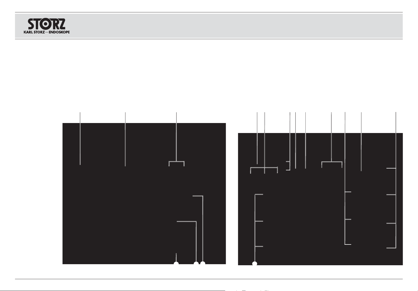
3 Bedienungselemente,
Anzeigen, Anschlüsse und
ihre Funktion
IMAGE1|S CONNECT in Kombination mit
H3-LINK-, X-LINK- und D3-LINK Modul
1
Netzschalter
2
Weißabgleich
3
USB-Port
4
Potentialausgleichsanschluss
5
LINK-Eingänge
6
SCB Ein-/Ausgangsbuchsen
(KARL|STORZ|Communication Bus)
7
LAN-Schnittstelle
8
USB-Schnittstelle
9
Videoausgangsbuchsen HD DVI-D
0
Potentialausgleichsanschluss
q
Videoausgang 3G-SDI
w
Netzanschlussbuchse
e
LINK-Ausgänge
r
Kameraanschluss H3-LINK
t
Kameraanschluss X-LINK
z
Kameraanschluss D3-LINK
3 Controls, displays,
connectors, and their uses
IMAGE1|S CONNECT in combination with the
H3-LINK, X-LINK and D3-LINK modules
1
Power switch
2
White balance
3
USB port
4
Potential equalization connector
5
LINK imputs
6
SCB input/output sockets
(KARL|STORZ|Communication Bus)
7
LAN interface
8
USB interface
9
HD DVI-D video output sockets
0
Potential equalization connector
q
3G-SDI video output
w
Power cord socket
e
LINK outputs
r
H3-LINK camera connector
t
X-LINK camera connector
z
D3-LINK camera connector
3 ƍƛƕƜƕƝƢƫ ƣƟƠƐƒƛƕƝƘƯ,
ƘƝƔƘƚƐƢƞƠƫ, ƠƐƗƪƕƜƫ Ƙ
Ƙƥ|ƤƣƝƚƦƘƘ
IMAGE1|S CONNECT ƒ ơƞƧƕƢƐƝƘƘ ơ
ƜƞƔƣƛƯƜƘ H3-LINK, X-LINK Ƙ D3-LINK
1
ƁƕƢƕƒƞƙ ƟƕƠƕƚƛƮƧƐƢƕƛƬ
2
űƐƛƐƝơ ƑƕƛƞƓƞ
3
ſƞƠƢ USB
4
ƀƐƗƪƕƜ ƔƛƯ ƒƫƠƐƒƝƘƒƐƝƘƯ ƟƞƢƕƝƦƘƐƛƞƒ
5
ŲƥƞƔƫ LINK
6
ųƝƕƗƔƐ ƒƥƞƔƐ/ƒƫƥƞƔƐ SCB
(KARL|STORZ|Communication Bus)
7
ŸƝƢƕƠƤƕƙơ LAN
8
ŸƝƢƕƠƤƕƙơ USB
9
ųƝƕƗƔƐ ƒƘƔƕƞƒƫƥƞƔƐ HD DVI-D
0
ƀƐƗƪƕƜ ƔƛƯ ƒƫƠƐƒƝƘƒƐƝƘƯ ƟƞƢƕƝƦƘƐƛƞƒ
q
ŲƘƔƕƞƒƫƥƞƔ 3G-SDI
w
ųƝƕƗƔƞ ƟƞƔƚƛƮƧƕƝƘƯ ƚ ơƕƢƘ
e
ŲƫƥƞƔƫ LINK
r
ƀƐƗƪƕƜ ƟƞƔƚƛƮƧƕƝƘƯ ƚƐƜƕƠƫ H3-LINK
t
ƀƐƗƪƕƜ Ɵƞ
z
ƀƐƗƪƕƜ ƟƞƔƚƛƮƧƕƝƘƯ ƚƐƜƕƠƫ D3-LINK
ƔƚƛƮƧƕƝƘƯ ƚƐƜƕƠƫ X-LINK
V

Symbolerläuterungen
Symbols employed ſƞƯơƝƕƝƘƕ ơƘƜƒƞƛƞƒ
4 Symbolerläuterungen
4. 1 Symbole zur Bedienung
Gerät Typ CF/Defib. resistent Type CF device/Defib. resistant
Standby/Ein/Aus Standby/On/Off ƀƕƖƘƜ ƞƖƘƔƐƝƘƯ/ŲźŻ/ŲƋźŻ
USB 2.0 USB 2.0 USB 2.0
Gebrauchsanweisung befolgen Follow instructions for use
Weißabgleich White balance űƐƛƐƝơ ƑƕƛƞƓƞ
Potentialausgleich Potential equalization ŲƫƠƐƒƝƘƒƐƝƘƕ ƟƞƢƕƝƦƘƐƛƞƒ
4 Symbols employed
4. 1 Symbols for operation
4 ſƞƯơƝƕƝƘƕ ơƘƜƒƞƛƞƒ
4. 1 ƁƘƜƒƞƛƫ ƔƛƯ ƭƚơƟƛƣƐƢƐƦƘƘ
ſƠƘƑƞƠ ƢƘƟƐ CF/ơ ƗƐƩƘƢƞƙ ƞƢ ƒƞƗƔƕƙơƢƒƘƯ
ƔƕƤƘƑƠƘƛƛƯƢƞƠƐ
ƁƛƕƔƣƙƢƕ ƣƚƐƗƐƝƘƯƜ ƘƝơƢƠƣƚƦƘƘ Ɵƞ
ƭƚơƟƛƣƐƢƐƦƘƘ
VI

Symbolerläuterungen
Symbols employed ſƞƯơƝƕƝƘƕ ơƘƜƒƞƛƞƒ
60°C
(140°F)
10
14
SN
Rx ONLY
4. 2 Symbole auf Label und
Verpackung
4. 2 Label and packaging
symbols
4. 2 ƁƘƜƒƞƛƫ ƝƐ ƭƢƘƚƕƢƚƕ Ƙ
ƣƟƐƚƞƒƚƕ
Zerbrechlich, mit Sorgfalt handhaben Fragile, handle with care ƅƠƣƟƚƞƕ, ƞƑƠƐƩƐƢƬơƯ ƞơƢƞƠƞƖƝƞ
Trocken aufbewahren Keep dry űƕƠƕƧƬ ƞƢ ƒƛƐƓƘ
Lagertemperatur
-10 °C...+60 °C
Storage temperature
-10 °C...+60 °C
ƂƕƜƟƕƠƐƢƣƠƐ ƥƠƐƝƕƝƘƯ
-10 °C...+60 °C
Seriennummer Serial number ƁƕƠƘƙƝƫƙ ƝƞƜƕƠ
Anzahl der Produkte in der Produktverpackung Number of products in the product packaging źƞƛƘƧƕơƢƒƞ ƘƗƔƕƛƘƙ ƒ ƣƟƐƚƞƒƚƕ
CE-Kennzeichnung CE mark ŷƝƐƚ CE
oben This side up ŲƕƠƥ
Nach US-amerikanischem Bundesrecht (21 CFR
801.109) darf dieses Produkt nur an oder auf
Verschreibung durch einen Arzt („licensed physician“) verkauft werden.
Federal (USA) law restricts this device to sale by
or on the order of a physician.
Ų ơƞƞƢƒƕƢơƢƒƘƘ ơ ƤƕƔƕƠƐƛƬƝƫƜ
ƗƐƚƞƝƞƔƐƢƕƛƬơƢƒƞƜ ƁƈŰ (ơƞƓƛƐơƝƞ 21 CFR
801.109) ƘƗƔƕƛƘƕ ƠƐƗƠƕƨƕƝƞ ƟƠƞƔƐƒƐƢƬ
ƢƞƛƬƚƞ ƒƠƐƧƐƜ (ƘƜƕƮƩƘƜ ƛƘƦƕƝƗƘƮ) ƘƛƘ Ɵƞ
ƠƕƦƕƟƢƣ ƒƠƐƧƐ.
Anleitung beachten Refer to instruction manual ƁƞƑƛƮƔƐƙƢƕ ƠƣƚƞƒƞƔơƢƒƞ
Hersteller Manufacturer ŸƗƓƞƢƞƒƘƢƕƛƬ
VII
nicht-ionisierende elektromagnetische Strahlung Non-ionizing electromagnetic radiation
Dieses Gerät ist entsprechend der europäischen
Richtlinie über Elektro- und Elektronik-Altgeräte
(waste electrical and electronic equipment –
WEEE) gekennzeichnet.
This device has been marked in accordance
with the European Directive on waste electrical
and electronic equipment (WEEE).
ŽƕƘƞƝƘƗƘƠƣƮƩƕƕ ƭƛƕƚƢƠƞƜƐƓƝƘƢƝƞƕ
ƘƗƛƣƧƕƝƘƕ
ŴƐƝƝƫƙ ƟƠƘƑƞƠ ƜƐƠƚƘƠƞƒƐƝ ƒ ơƞƞƢƒƕƢơƢƒƘƘ
ơ ŵƒƠƞƟƕƙơƚƞƙ ŴƘƠƕƚƢƘƒƞƙ ƞƑ ƞƢƥƞƔƐƥ
ƭƛƕƚƢƠƘƧƕơƚƞƓƞ Ƙ ƭƛƕƚƢƠƞƝƝƞƓƞ
ƞƑƞƠƣƔƞƒƐƝƘƯ (WEEE).

Inhalt
Contents ƁƞƔƕƠƖƐƝƘƕ
1 Wichtiger Hinweis für die Benutzer
von KARL STORZ Geräten ....................... III
2 Geräteabbildungen ................................... IV
2. 1 IMAGE1 S
Kombinationsmöglichkeiten ....................IV
3 Bedienungselemente, Anzeigen,
Anschlüsse und ihre Funktion .................. V
4 Symbolerläuterungen ............................... VI
4. 1 Symbole zur Bedienung ..........................VI
4. 2 Symbole auf Label und
Verpackung ...........................................VII
5 Allgemeines .................................................4
5. 1 Gerätebeschreibungen ............................4
5. 2 Schutzrechte ...........................................4
6 Sicherheitshinweise ....................................5
6. 1 Erklärung zu Warn- und
Vorsichtshinweisen ..................................5
6. 2 Allgemeine Sicherheitshinweise ................6
6. 3 Bestimmungsgemäßer Gebrauch ..........10
6. 3. 1 Zweckbestimmung ................................10
6. 4 Kontraindikationen .................................10
6. 5 Profil des Patienten ................................11
6. 6 Profil des Anwenders
(Facharzt) ...............................................11
6. 7 Profil des Anwenders
(Hilfsperson) ...........................................12
6. 8 Sicherheitsmaßnahmen am
Aufstellort ..............................................13
6. 9 Sicherheitsmaßnahmen
beim Einsatz des Gerätes ......................13
7 Inbetriebnahme .........................................14
7. 1 Grundausstattung ..................................14
7. 1. 1 TC 200 IMAGE1 S CONNECT ...............14
7. 1. 2 TC 300 IMAGE1 S H3-LINK ...................14
7. 1. 3 TC 301 IMAGE1 S X-LINK .....................14
7. 1. 4 TC 302 IMAGE1 S D3-LINK ...................14
7. 2 Auspacken des Gerätes ........................14
7. 3 Gerät für Anwendung
vorbereiten.............................................15
7. 3. 1 Aufstellen ...............................................15
7. 3. 2 Potentialausgleich
anschließen............................................15
7. 3. 3 IMAGE1 S LINK-Module mit IMAGE1 S
CONNECT verbinden .............................15
7. 3. 4 SCB-Verbindung herstellen ....................15
1 Important information for users of
KARL STORZ devices ............................... III
2 Images of the equipment ......................... IV
2. 1 Possible combinations for
IMAGE1 S ..............................................IV
3 Controls, displays,
connectors, and their uses ....................... V
4 Symbols employed .................................... VI
4. 1 Symbols for operation .............................VI
4. 2 Label and packaging
symbols .................................................VII
5 General information ....................................4
5. 1 Description of the devices........................4
5. 2 Property rights .........................................4
6 Safety instructions ......................................5
6. 1 Explanation of warnings and
cautions ...................................................5
6. 2 General safety information .......................6
6. 3 Indications for use .................................10
6. 3. 1 Intended use ..........................................10
6. 4 Contraindications ...................................10
6. 5 Patient profile .........................................11
6. 6 User profile
(specialist physician) ..............................11
6. 7 User profile
(assistant) ..............................................12
6. 8 Safety precautions at the site of
installation ..............................................13
6. 9 Safety precautions
when operating the device .....................13
7 Initial operation .........................................14
7. 1 Basic equipment ....................................14
7. 1. 1 TC 200 IMAGE1 S CONNECT ...............14
7. 1. 2 TC 300 IMAGE1 S H3-LINK ...................14
7. 1. 3 TC 301 IMAGE1 S X-LINK .....................14
7. 1. 4 TC 302 IMAGE1 S D3-LINK ...................14
7. 2 Unpacking the equipment ......................14
7. 3 Preparing the device for use ..................15
7. 3. 1 Installation ..............................................15
7. 3. 2 Connecting the potential
equalization............................................15
7. 3. 3 Connecting the IMAGE1 S LINK module
with IMAGE1 S CONNECT ...................15
7. 3. 4 Connecting SCB ....................................15
1 ŲƐƖƝƐƯ ƘƝƤƞƠƜƐƦƘƯ
ƔƛƯ ƛƘƦ, ƟƞƛƬƗƣƮƩƘƥơƯ
ƟƠƘƑƞƠƐƜƘ KARL STORZ ........................ III
2 ƁƞƟƠƞƒƞƔƘƢƕƛƬƝƫƕ
2. 1 ŲƞƗƜƞƖƝƞơƢƘ ơƞƧƕƢƐƝƘƯ
IMAGE1 S ...............................................IV
3 ƍƛƕƜƕƝƢƫ ƣƟƠƐƒƛƕƝƘƯ, ƘƝƔƘƚƐƢƞƠƫ,
ƠƐƗƪƕƜƫ Ƙ Ƙƥ ƤƣƝƚƦƘƘ ............................ V
4 ſƞƯơƝƕƝƘƕ ơƘƜƒƞƛƞƒ .............................. VI
4. 1 ƁƘƜƒƞƛƫ ƔƛƯ ƭƚơƟƛƣƐƢƐƦƘƘ..................VI
4. 2 ƁƘƜƒƞƛƫ ƝƐ ƭƢƘƚƕƢƚƕ Ƙ ƣƟƐƚƞƒƚƕ .......VII
5 žƑƩƐƯ ƘƝƤƞƠƜƐƦƘƯ ..................................4
5. 1 žƟƘơƐƝƘƕ ƟƠƘƑƞƠƞƒ ...............................4
5. 2 ŰƒƢƞƠơƚƞƕ ƟƠƐƒƞ ....................................4
6 ƃƚƐƗƐƝƘƯ Ɵƞ ƢƕƥƝƘƚƕ ƑƕƗƞƟƐơƝƞơƢƘ .......5
6. 1 ſƞƯơƝƕƝƘƕ ƟƠƕƔƣƟƠƕƔƘƢƕƛƬƝƞƙ
ƘƝƤƞƠƜƐƦƘƘ ...........................................5
6. 2 žƑƩƘƕ ƣƚƐƗƐƝƘƯ Ɵƞ ƢƕƥƝƘƚƕ
ƑƕƗƞƟƐơƝƞơƢƘ .........................................6
6. 3 ŸơƟƞƛƬƗƞƒƐƝƘƕ Ɵƞ ƝƐƗƝƐƧƕƝƘƮ ...........10
6. 3. 1 Ɔƕƛƕƒƞƕ
6. 4 ſƠƞƢƘƒƞƟƞƚƐƗƐƝƘƯ ...............................10
6. 5 ſƠƞƤƘƛƬ ƟƐƦƘƕƝƢƐ ...............................11
6. 6 ſƠƞƤƘƛƬ ƟƞƛƬƗƞƒƐƢƕƛƯ
(ƒƠƐƧ-ơƟƕƦƘƐƛƘơƢ) ................................11
6. 7 ſƠƞƤƘƛƬ ƟƞƛƬƗƞƒƐƢƕƛƯ (ƐơơƘơƢƕƝƢ) ....12
6. 8 żƕƠƫ ƑƕƗƞƟƐơƝƞơƢƘ ƝƐ ƜƕơƢƕ
ƣơƢƐƝƞƒƚƘ .............................................13
6. 9 żƕƠƫ ƑƕƗƞƟƐơƝƞơƢƘ ƟƠƘ
ƠƐƑƞƢƕ ơ ƟƠƘƑƞƠƞƜ ..............................13
7 ŲƒƞƔ ƒ ƭƚơƟƛƣƐƢƐƦƘƮ .............................14
7. 1 žơƝƞƒƝƞƙ ƚƞƜƟƛƕƚƢ ƟƞơƢƐƒƚƘ .............14
7. 1. 1 TC 200 IMAGE1 S CONNECT ...............14
7. 1. 2 TC 300 IMAGE1 S H3-LINK ...................14
7. 1. 3 TC 301 IMAGE1 S X-LINK .....................14
7. 1. 4 TC 302 IMAGE1 S D3-LINK ...................14
7. 2 ƀƐơƟƐƚƞƒƚƐ ƟƠƘƑƞƠƐ ............................14
7. 3 ſƞƔƓƞƢƞƒƚƐ ƟƠƘƑƞƠƐ ƚ
ƘơƟƞƛƬƗƞƒƐƝƘƮ ....................................15
7. 3. 1 ƃơƢƐƝƞƒƚƐ .............................................15
7. 3. 2 ſƞƔƚƛƮƧƕƝƘƕ ƚƐƑƕƛƯ ƔƛƯ
ƒƫƠƐƒƝƘƒƐƝƘƯ ƟƞƢƕƝƦƘƐƛƞƒ ................15
7. 3. 3 ſƞƔƚƛƮƧƕƝƘƕ ƜƞƔƣƛƕƙ IMAGE1
LINK ƚ IMAGE1
7. 3. 4 ſƞƔƚƛƮƧƕƝƘƕ SCB ...............................15
ƘƛƛƮơƢƠƐƦƘƘ ........
ƝƐƗƝƐƧƕƝƘƕ ............................
S CONNECT ................15
10
IV
1

Inhalt
Contents ƁƞƔƕƠƖƐƝƘƕ
7. 3. 5 Monitor anschließen ...............................16
7. 3. 6 Anschließen von USB-Geräten .............16
7. 3. 7 Netzverbindung herstellen ......................16
7. 3. 8 IMAGE1 S CONNECT einschalten ......... 17
7. 3. 9 USB-Speichermedium verbinden ...........17
7. 3. 10 Kamerakopf/Videoendoskop
anschließen............................................17
7. 3. 11 Weißabgleich durchführen .....................17
7. 3. 12 Funktionstest ........................................18
7. 3. 13 Installationsübersicht ..............................19
8 Bedienhinweise .........................................20
8. 1 Grundsätzliches zur
Bedienung .............................................20
8. 1. 1 Tastatur und Maus ................................20
8. 1. 2 Kamerakopftasten .................................20
8. 2 Dashboard .............................................20
8. 2. 1 Funktionsbeschreibung der
verwendeten Symbole ...........................21
8. 3 Live-Menü ..............................................25
8. 3. 1 Funktionsbeschreibung der
verwendeten Symbole ...........................26
8. 4 Setup-Menü ...........................................31
8. 4. 1 Allgemeine Einstellungen
(IMAGE1 S CONNECT) ..........................31
8. 4. 2 Voreinstellungen ....................................35
8. 4. 3 LINK-spezifische Einstellungen ..............35
9 Reinigung, Desinfektion,
Pflege und Sterilisation ............................36
9. 1 Allgemeine Sicherheitshinweise ..............36
9. 2 Wischdesinfektion von Geräten ..............37
10 Instandhaltung...........................................38
10. 1 Wartung und
Sicherheitsüberprüfung ..........................38
10. 1. 1 Wartung .................................................38
10. 1. 2 Sicherheitsüberprüfung ..........................38
10. 2 Instandsetzung ......................................39
10. 3 Entsorgung ............................................39
10. 4 Reparaturprogramm ..............................40
10. 5 Verantwortlichkeit ..................................41
10. 6 Garantie .................................................41
11 Technische Beschreibung ........................42
11. 1 Technische Daten ..................................42
11. 2 Technische Unterlagen ..........................43
11. 3 Normenkonformität ................................43
2
7. 3. 5 Connecting the monitor .........................16
7. 3. 6 Connecting USB devices .......................16
7. 3. 7 Connecting the power supply ................16
7. 3. 8 Switching on the IMAGE1 S CONNECT 17
7. 3. 9 Connecting USB storage media ............17
Connecting the camera head/video
7. 3. 10
endoscope ...........................................17
7. 3. 11 Performing the white balance ................17
7. 3. 12 Test for proper functioning .....................18
7. 3. 13 Installation overview ...............................19
8 Operating instructions ..............................20
8. 1 Basic information on
operation ...............................................20
8. 1. 1 Keyboard and mouse ............................20
8. 1. 2 Camera head buttons ............................20
8. 2 Dashboard .............................................20
8. 2. 1 Description of functions
of the symbols used ..............................21
8. 3 Live Menu ..............................................25
8. 3. 1 Description of functions
of the symbols used ..............................26
8. 4 Setup Menu ...........................................31
8. 4. 1 General Settings
(IMAGE1 S CONNECT) ..........................31
8. 4. 2 Presets ..................................................35
8. 4. 3 LINK-specific settings ............................35
9 Cleaning, disinfection,
care and sterilization ................................36
9. 1 General safety information .....................36
9. 2 Wipe-down disinfection of devices .........37
10 Service and repair .....................................38
10. 1 Maintenance and
safety check ..........................................38
10. 1. 1 Maintenance ..........................................38
10. 1. 2 Safety check ..........................................38
10. 2 Servicing and repair ...............................39
10. 3 Disposal .................................................39
10. 4 Repair program......................................40
10. 5 Limitation of liability ................................41
10. 6 Warranty ................................................41
11 Technical description ...............................42
11. 1 Technical data .......................................42
11. 2 Technical documentation .......................43
11. 3 Standard compliance .............................43
7. 3. 5 ſƞƔƚƛƮƧƕƝƘƕ ƜƞƝƘƢƞƠƐ.......................16
7. 3. 6 ſƞƔƚƛƮƧƕƝƘƕ USB-ƟƠƘƑƞƠƞƒ ..............16
7. 3. 7 ſƞƔƚƛƮƧƕƝƘƕ ƚ ơƕƢƘ ............................16
7. 3. 8 ŲƚƛƮƧƕƝƘƕ IMAGE1 S CONNECT ........17
7. 3. 9 ſƞƔƚƛƮƧƕƝƘƕ USB-ƝƐƚƞƟƘƢƕƛƯ ...........17
7. 3. 10 ſƞƔƚƛƮƧƕƝƘƕ ƒƘƔƕƞƓƞƛƞƒƚƘ/
ƒƘƔƕƞƭƝƔƞơƚƞƟƐ ...................................17
7. 3. 11 ŽƐơƢƠƞƙƚƐ ƑƐƛƐƝơƐ ƑƕƛƞƓƞ..................17
7. 3. 12 ſƠƞƒƕƠƚƐ ƤƣƝƚƦƘƞƝƘƠƞƒƐƝƘƯ .............18
7. 3. 13 žƑƗƞƠ ƣơƢƐƝƞƒƚƘ ..................................19
8 ƃƚƐƗƐƝƘƯ Ɵƞ ƭƚơƟƛƣƐƢƐƦƘƘ ....................20
8. 1 žơƝƞƒƝƫƕ ơƒƕƔƕƝƘƯ ƔƛƯ
ƭƚơƟƛƣƐƢƐƦƘƘ ........................................20
8. 1. 1
źƛƐƒƘƐƢƣƠƐ Ƙ ƜƫƨƬ .............................
8. 1. 2 źƝƞƟƚƘ ƒƘƔƕƞƓƞƛƞƒƚƘ ..........................20
8. 2 ŸƝƤƞƠƜƐƦƘƞƝƝƐƯ ƟƐƝƕƛƬ ....................20
8. 2. 1 žƟƘơƐƝƘƕ ƤƣƝƚƦƘƙ ƘơƟƞƛƬƗƣƕƜƫƥ
ơƘƜƒƞƛƞƒ ..............................................21
8. 3 ŶƘƒƞƕ ƜƕƝƮ .........................................25
8. 3. 1 žƟƘơƐƝƘƕ ƤƣƝƚƦƘƙ
ƘơƟƞƛƬƗƣƕƜƫƥ ơƘƜƒƞƛƞƒ ......................26
8. 4 żƕƝƮ ƝƐơƢƠƞƕƚ ....................................31
8. 4. 1 žƑƩƘƕ ƝƐơƢƠƞƙƚƘ
(IMAGE1 CONNECT) .............................31
8. 4. 2 ſƠƕƔƒƐƠƘƢƕƛƬƝƫƕ ƝƐơƢƠƞƙƚƘ ..............35
8. 4. 3 ƁƟƕƦƘƤƘƧƕơƚƘƕ ƝƐơƢƠƞƙƚƘ LINK .........35
9 žƧƘơƢƚƐ, ƔƕƗƘƝƤƕƚƦƘƯ,
ơƢƕƠƘƛƘƗƐƦƘƯ Ƙ ƣƥƞƔ ...............................36
9. 1 žƑƩƘƕ ƣƚƐƗƐƝƘƯ Ɵƞ ƢƕƥƝƘƚƕ
ƑƕƗƞƟƐơƝƞơƢƘ .......................................36
9. 2 ŴƕƗƘƝƤƕƚƦƘƯ ƟƠƘƑƞƠƞƒ ƟƣƢƕƜ
ƟƠƞƢƘƠƐƝƘƯ ...........................................37
10 ƂƕƥƝƘƧƕơƚƘƙ ƣƥƞƔ ....................................38
10. 1 ƂƕƥƞƑơƛƣƖƘƒƐƝƘƕ Ƙ ƘơƟƫƢƐƝƘƯ
ƔƛƯ ƞƦƕƝƚƘ ƑƕƗƞƟƐơƝƞơƢƘ ....................
10. 1. 1 ƂƕƥƞƑơƛƣƖƘƒƐƝƘƕ .................................38
10. 1. 2 ŸơƟƫƢƐƝƘƯ ƔƛƯ ƞƦƕƝƚƘ ƑƕƗƞƟƐơƝƞơƢƘ .38
10. 2 ƀƕƜƞƝƢ ..................................................39
10. 3 ƃƢƘƛƘƗƐƦƘƯ ...........................................39
10. 4 ƀƕƜƞƝƢƝƐƯ ƟƠƞƓƠƐƜƜƐ .........................40
10. 5 žƢƒƕƢơƢƒƕƝƝƞơƢƬ ..................................41
10. 6 ųƐƠƐƝƢƘƯ ...............................................41
11 ƂƕƥƝƘƧƕơƚƞƕ ƞƟƘơƐƝƘƕ ...........................42
11. 1 ƂƕƥƝƘƧƕơƚƘƕ ƔƐƝƝƫƕ ............................42
11. 2 ƂƕƥƝƘƧƕơƚƐƯ ƔƞƚƣƜƕƝƢƐƦƘƯ .................43
11. 3 ƁƞƞƢƒƕƢơƢƒƘƕ ơƢƐƝƔƐƠƢƐƜ ...................43
20
38

Inhalt
Contents ƁƞƔƕƠƖƐƝƘƕ
11. 4 Richtlinienkonformität
für IMAGE1 S (TC 200,
TC 300, TC 301 und TC 302) .................44
11. 5 Software-Eigentum und
Lizenzvergabe ........................................44
12 Ersatzteile,
empfohlenes Zubehör ..............................46
12. 1 Kompatible Kameraköpfe
für IMAGE1 S H3-LINK TC 300
mit S-Technologien ................................46
12. 2 Kompatible Kameraköpfe
für IMAGE1 S H3-LINK TC 300
ohne S-Technologien .............................46
12. 3 Kompatible Kameraköpfe
für IMAGE1 S X-LINK TC 301
mit S-Technologien ................................47
12. 4 Kompatible Kameraköpfe
für IMAGE1 S X-LINK TC 301
ohne S-Technologien .............................47
12. 5 Kompatible Videoendoskope
für IMAGE1 S X-LINK TC 301
mit S-Technologien ................................47
12. 6 Kompatible Videoendoskope und
Kameraköpfe für IMAGE1 S D3-LINK
TC 302 mit S-Technologien....................49
12. 7 Empfohlenes Zubehör ............................50
12. 8 Bedienbare SCB-Lichtquellen ................51
12. 9 Bedienbare SCB-Insufflatoren ................51
12. 10 Kompatible 3D-Monitore ........................51
13 Hinweise zur elektromagnetischen
Verträglichkeit (EMV) ................................52
13. 1 EMV Tabellen für IMAGE1 S ..................54
14 Niederlassungen .......................................66
11. 4 Directive compliance
for IMAGE1 S (TC 200,
TC 300, TC 301 and TC 302) .................44
11. 5 Software ownership and
licensing ................................................44
12 Spare parts,
recommended accessories......................46
12. 1 Compatible camera heads
for IMAGE1 S H3-LINK TC 300
with S technologies ...............................46
12. 2 Compatible camera heads
for IMAGE1 S H3-LINK TC 300
without S technologies ..........................46
12. 3 Compatible camera heads
for IMAGE1 S X-LINK TC 301
with S technologies................................47
12. 4 Compatible camera heads
for IMAGE1 S X-LINK TC 301
without S technologies...........................47
12. 5 Compatible video endoscopes
for IMAGE1 S X-LINK TC 301
with S technologies ...............................47
12. 6 Compatible video endoscopes and
camera heads for IMAGE1 S D3-LINK
TC 302 with S technology ......................49
12. 7 Recommended accessories ..................50
12. 8 Operable SCB light sources...................51
12. 9 Operable SCB insufflators ......................51
12. 10 Compatible 3D monitors ........................51
13 Information on electromagnetic
compatibility (EMC) ...................................52
13. 1 EMV tables for IMAGE1 S ......................54
14 Subsidiaries ...............................................66
11. 4 ƁƞƞƢƒƕƢơƢƒƘƕ ƔƘƠƕƚƢƘƒƐƜ
ƔƛƯ IMAGE1 S (TC 200,
TC 300, TC 301 Ƙ TC 302) .....................44
11. 5 ſƠƐƒƐ ơƞƑơƢƒƕƝƝƞơƢƘ ƝƐ
ƟƠƞƓƠƐƜƜƝƞƕ ƞƑƕơƟƕƧƕƝƘƕ Ƙ
ƟƠƕƔƞơƢƐƒƛƕƝƘƕ ƛƘƦƕƝƗƘƙ ...................44
12 ŷƐƟƧƐơƢƘ, ƠƕƚƞƜƕƝƔƣƕƜƫƕ
ƟƠƘƝƐƔƛƕƖƝƞơƢƘ ......................................46
12. 1 ƁƞƒƜƕơƢƘƜƫƕ ƒƘƔƕƞƓƞƛƞƒƚƘ
ƔƛƯ IMAGE1 S H3-LINK TC 300
ơ S-ƢƕƥƝƞƛƞƓƘƯƜƘ .................................
12. 2 ƁƞƒƜƕơƢƘƜƫƕ ƒƘƔƕƞƓƞƛƞƒƚƘ
ƔƛƯ IMAGE1 S H3-LINK TC 300
ƑƕƗ S-ƢƕƥƝƞƛƞƓƘƙ .................................46
12. 3 ƁƞƒƜƕơƢƘƜƫƕ ƒƘƔƕƞƓƞƛƞƒƚƘ
ƔƛƯ IMAGE1 S X-LINK TC 301
ơ S-ƢƕƥƝƞƛƞƓƘƯƜƘ .................................47
12. 4 ƁƞƒƜƕơƢƘƜƫƕ ƒƘƔƕƞƓƞƛƞƒƚƘ
ƔƛƯ IMAGE1 S X-LINK TC 301
ƑƕƗ S-ƢƕƥƝƞƛƞƓƘƙ .................................47
12. 5 ƁƞƒƜƕơƢƘƜƫƕ ƒƘƔƕƞ ƭƝƔƞơƚƞƟƫ
ƔƛƯ IMAGE1 S X-LINK TC 301
ơ S-ƢƕƥƝƞƛƞƓƘƯƜƘ .................................47
12. 6 ƁƞƒƜƕơƢƘƜƫƕ ƒƘƔƕƞƭƝƔƞơƚƞƟƫ
Ƙ ƒƘƔƕƞƓƞƛƞƒƚƘ ƔƛƯ IMAGE1 S
D3-LINK TC 302 ơ S-ƢƕƥƝƞƛƞƓƘƯƜƘ ......49
12. 7 ƀƕƚƞƜƕƝƔƣƕƜƫƕ ƟƠƘƝƐƔƛƕƖƝƞơƢƘ .......50
12. 8 ƃƟƠƐƒƛƯƕƜƫƕ ƘơƢƞƧƝƘƚƘ ơƒƕƢƐ SCB ...51
12. 9 ƃƟƠƐƒƛƯƕƜƫƕ ƘƝơƣƤƤƛƯƢƞƠƫ SCB .....51
12. 10 ƁƞƒƜƕơƢƘƜƫƕ 3D-ƜƞƝƘƢƞƠƫ ................51
13 ƃƚƐƗƐƝƘƯ Ɵƞ ƭƛƕƚƢƠƞƜƐƓƝƘƢƝƞƙ
ơƞƒƜƕơƢƘƜƞơƢƘ (ƍżƁ) .............................52
13. 1 ƂƐƑƛƘƦƫ Ɵƞ ƍżƁ ƔƛƯ IMAGE1
14 ƄƘƛƘƐƛƫ ....................................................66
46
S .........54
3

Allgemeines
General information
žƑƩƐƯ ƘƝƤƞƠƜƐƦƘƯ
5 Allgemeines
5. 1 Gerätebeschreibungen
Die IMAGE1|S verfolgt einen völlig neuartigen
und innovativen Weg in der Systemkonzeption.
Der modulare Ansatz im Baukastenprinzip
erlaubt dem Anwender ein auf ihn abgestimmtes
System. Das Modul IMAGE1|S CONNECT bildet
das Herzstück der IMAGE1|S und dient als
Kommunikationsschnittstelle zwischen Bild- und
Dokumentationsgeräten.
Zur Anwendung wird die IMAGE1|S CONNECT
und mindestens ein LINK-Modul benötigt, das
das Signal aufnimmt und weiterleitet. Durch die
Light Source Control und die S-Technologien zur
Bildoptimierung wird der Anwender umfangreicher
bei seiner Tätigkeit unterstützt. Eine intuitive
Benutzeroberfläche sorgt für den einfachen,
schnellen Zugriff und ein rasches Verständnis der
Menüführung.
Das System bietet zahlreiche Funktionen auf dem
neuesten Stand der Technik. Hierzu zählen:
• IMAGE1|S Visualisierungsmodi zur
Unterstützung des Anwenders durch
Kontrastanhebung oder/und gleichmäßiger
Helligkeitswahrnehmung
• Light Source Control zur automatischen
Steuerung der Lichtquelle
• Integrierte Bild- und Videoaufnahme zur
einfachen Dokumentation
Eine genaue Beschreibung der Funktionen finden
Sie im Kapitel 8.4.
5. 2 Schutzrechte
Dieses Produkt ist in den USA geschützt durch
(mindestens eines der folgenden) US-Patent/e
7,821,530; 8,274,559; 7,520,853; 5,716,323;
5,788,688; 5,913,817; 6,397,286; 6,484,221;
7,212,227; US 8,089,509; US 8,199,188.
Besuchen Sie für weitere Informationen
www.karlstorz.com.
5 General information
5. 1 Description of the devices
The IMAGE1|S takes a unique and innovative
approach to system conception. The modular
design principle allows the user to create a system
which is tailored to his needs. The IMAGE1|S
CONNECT module is at the heart of the
IMAGE1|S and acts as a communication interface
between the image and documentation devices.
For use, one IMAGE1|S CONNECT plus at least
one LINK module is required which receives and
forwards the signal. The Light Source Control and
S technologies for image optimization provide
users with even more comprehensive support. An
intuitive user interface assures simple and quick
access as well as rapid understanding of menu
navigation.
The system offers numerous state-of-the-art
functions. These include:
• IMAGE1|S visualization modes to assist the user
via contrast enhancement and/or more even
brightness perception
• Light Source Control for automatic adjustment
of the light source
• Integrated image and video capture for simple
documentation
Functions are described in greater detail in § 8.4.
5. 2 Property rights
Protected by at least one of the following US
Patents: 7,821,530; 8,274,559; 7,520,853;
5,716,323; 5,788,688; 5,913,817; 6,397,286;
6,484,221; 7,212,227; US 8,089,509;
US|8,199,188.
visit: www.karlstorz.com.
For more information,
5 žƑƩƐƯ ƘƝƤƞƠƜƐƦƘƯ
5. 1 žƟƘơƐƝƘƕ ƟƠƘƑƞƠƞƒ
Ų ƟƠƘƑƞƠƕ IMAGE1|S ƠƕƐƛƘƗƞƒƐƝ ơƞƒƕƠƨƕƝƝƞ Ɲƞƒƫƙ ƟƞƔƥƞƔ ƚ ƚƞƝƦƕƟƦƘƘ ơƘơƢƕƜƫ.
żƞƔƣƛƬƝƫƙ ƟƞƔƥƞƔ ƟƞƗƒƞƛƯƕƢ ƟƞƛƬƗƞƒƐƢƕƛƮ
ƟƞƛƣƧƘƢƬ ơƘơƢƕƜƣ, ƐƔƐƟƢƘƠƞƒƐƝƝƣƮ ƚ ƕƓƞ
ƟƞƢƠƕƑƝƞơƢƯƜ. żƞƔƣƛƬ IMAGE1|S CONNECT
ƯƒƛƯƕƢơƯ ƞơƝƞƒƞƙ ƟƠƘƑƞƠƐ IMAGE1|S Ƙ ơƛƣƖƘƢ
ƚƞƜƜƣƝƘƚƐƦƘƞƝƝƫƜ ƘƝƢƕƠƤƕƙơƞƜ ƜƕƖƔƣ ƟƠƘƑƞƠƐƜƘ ƠƐƑƞƢƫ ơ ƘƗƞƑƠƐƖƕƝƘƕƜ Ƙ ƟƠƘƑƞƠƐƜƘ
ƔƞƚƣƜƕƝƢƘƠƞƒƐƝƘƯ.
ŴƛƯ ƠƐƑƞƢƫ ƝƕƞƑƥƞƔƘƜ ƟƠƘƑƞƠ IMAGE1 S
CONNECT Ƙ Ɵƞ ƜƕƝƬƨƕƙ ƜƕƠƕ ƞƔƘƝ ƜƞƔƣƛƬ
LINK, ƟƠƘƝƘƜƐƮƩƘƙ ơƘƓƝƐƛ Ƙ ƟƕƠƕ
ƔƐƛƕƕ. Light Source Control (ƚƞƝƢƠƞƛƬ ƘơƢƞƧƝƘƚƐ
ơƒƕƢƐ) Ƙ S-ƢƕƥƝƞƛƞƓƘƘ ƔƛƯ ƞƟƢƘƜƘƗƐƦƘƘ
ƘƗƞƑƠƐƖƕƝƘƯ ƟƞƜƞƓƐƮƢ ƟƞƛƬƗƞƒƐƢƕƛƮ ƒ ƕƓƞ
ƠƐƑƞƢƕ. ŸƝƢƣƘƢƘƒƝƫƙ ƘƝƢƕƠƤƕƙơ ƟƞƛƬƗƞƒƐƢƕƛƯ
ƞƑƕơƟƕƧƘƒƐƕƢ ƟƠƞơƢƞƙ Ƙ ƑƫơƢƠƫƙ ƔƞơƢƣƟ, Ɛ
ƢƐƚƖƕ ƑƫơƢƠƞƕ ƟƞƝƘƜƐƝƘƕ ơƢƠƣƚƢƣƠƫ ƜƕƝƮ.
ƁƘơƢƕƜƐ ƟƠƕƔƞơƢƐƒƛƯƕƢ ƜƝƞƓƞƧƘơƛƕƝƝƫƕ
ƤƣƝƚƦƘƘ, ơƞƞƢƒƕƢơƢƒƣƮƩƘƕ ƝƞƒƕƙƨƕƜƣ ƣƠƞƒƝƮ
ƢƕƥƝƘƚƘ. ź ƝƘƜ ƞƢƝƞơƯƢơƯ:
• ƀƕƖƘƜƫ ƒƘƗƣƐƛƘƗƐƦƘƘ IMAGE1|S,
ƟƞƗƒƞƛƯƮƩƘƕ ƟƞƛƬƗƞƒƐƢƕƛƮ ƣƒƕƛƘƧƘƒƐƢƬ
ƚƞƝƢƠƐơƢ Ƙ/ƘƛƘ Ƒƞ
ƒƞơƟƠƘƯƢƘƕ ƯƠƚƞơƢƘ
• Light Source Control ƔƛƯ ƐƒƢƞƜƐƢƘƧƕơƚƞƓƞ
ƣƟƠƐƒƛƕƝƘƯ ƘơƢƞƧƝƘƚƞƜ ơƒƕƢƐ
• ŲơƢƠƞƕƝƝƐƯ ƤƣƝƚƦƘƯ ƗƐƟƘơƘ ƘƗƞƑƠƐƖƕƝƘƙ Ƙ
ƒƘƔƕƞ ƔƛƯ ƣƟƠƞƩƕƝƘƯ ƔƞƚƣƜƕƝƢƘƠƞƒƐƝƘƯ
ƂƞƧƝƞƕ ƞƟƘơƐƝƘƕ ƤƣƝƚƦƘƙ ƟƠƘƒƕƔƕƝƞ ƒ ƓƛƐƒƕ 8.4.
ƛƕƕ ƠƐƒƝƞƜƕƠƝƞƕ
5. 2 ŰƒƢƞƠơƚƞƕ ƟƠƐƒƞ
ŴƐƝƝƞƕ ƘƗƔƕƛƘƕ ƞƥƠƐƝƯƕƢơƯ ƒ ƁƈŰ
ƐƜƕƠƘƚƐƝơƚƘƜƘ ƟƐƢƕƝƢƐƜƘ (ƜƘƝƘƜƣƜ ƞƔƝƘƜ
ƘƗ ƟƕƠƕƧƘơƛƕƝƝƫƥ): 7,821,530; 8,274,559;
7,520,853; 5,716,323; 5,788,688; 5,913,817;
6,397,286; 6,484,221; 7,212,227; US 8,089,509;
US 8,199,188. ŴƞƟƞƛƝƘƢƕƛƬƝƫƕ ơƒƕƔƕƝƘƯ
ƜƞƖƝƞ ƝƐƙƢƘ ƝƐ ơƐƙƢƕ www.karlstorz.com.
ƔƐƮƩƘƙ ƕƓƞ
4

Sicherheitshinweise
Safety instructions
ƃƚƐƗƐƝƘƯ Ɵƞ ƢƕƥƝƘƚƕ
ƑƕƗƞƟƐơƝƞơƢƘ
6 Sicherheitshinweise
6. 1 Erklärung zu Warn- und
Vorsichtshinweisen
Sicherheitshinweise sind Maßnahmen zum Schutz
des Anwenders und Patienten vor Gefährdungen,
die durch den Gebrauch des Systems entstehen
können.
Bitte lesen Sie diese Gebrauchsanweisung sorgfältig durch und beachten Sie die Anwei sungen
genau. Die Bezeichnungen Warnung, Vorsicht
und Hinweis haben spezielle Bedeutungen. Wo
immer sie in der Gebrauchsanweisung verwendet werden, lesen Sie den nachfolgenden Text
genau, um einen sicheren und effizienten Be trieb
des Systems zu gewährleisten. Zur deutlicheren
Hervorhebung steht diesen Bezeich nungen ein
Piktogramm voran.
WARNUNG: Warnung macht auf eine Gefährdung des Patienten oder des Arztes
3
aufmerksam.
VORSICHT: Vorsicht macht darauf
aufmerksam, dass bestimmte Wartungs-
2
oder Sicherheitsmaßnahmen zu treffen
sind, um eine Beschädigung des Gerätes
zu vermeiden.
HINWEIS: Hinweise enthalten spezielle
1
Informationen zur Bedienung des Gerätes
oder sie er klären wichtige Informationen.
6 Safety instructions
6. 1 Explanation of warnings and
cautions
Safety instructions are measures intended to
protect the user and patients from the risks which
could arise through the use of the system.
Please read this manual and follow the instructions
carefully. The words Warning, Caution and Note
convey special meanings. Wherever they are used
in this manual, the accompanying text should be
carefully reviewed to ensure the safe and effective
operation of the system. To make these words
stand out more clearly, they are accompanied by
a pictogram.
WARNING: A Warning indicates that the
personal safety of the patient or physician
3
is at risk.
CAUTION: A Caution indicates that
particular service procedures or
2
precautions must be followed to avoid
possible damage to the device.
NOTE: A Note indicates special information
1
about operating the device or clarifies
important information.
6 ƃƚƐƗƐƝƘƯ Ɵƞ ƢƕƥƝƘƚƕ
ƑƕƗƞƟƐơƝƞơƢƘ
6. 1 ſƞƯơƝƕƝƘƕ ƟƠƕƔƣƟƠƕƔƘƢƕƛƬƝƞƙ ƘƝƤƞƠƜƐƦƘƘ
ƃƚƐƗƐƝƘƯ Ɵƞ ƢƕƥƝƘƚƕ ƑƕƗƞƟƐơƝƞơƢƘ – ƭƢƞ
ƜƕƠƫ Ɵƞ ƗƐƩƘƢƕ ƟƞƛƬƗƞƒƐƢƕƛƯ Ƙ ƟƐƦƘƕƝƢƐ
ƞƢ ƞƟƐơƝƞơƢƕƙ, ƚƞƢƞƠƫƕ ƜƞƓƣƢ ƒƞƗƝƘƚƝƣƢƬ ƒ
ƠƕƗƣƛƬƢƐƢƕ ƘơƟƞƛƬƗƞƒƐƝƘƯ ơƘơƢƕƜƫ.
ŲƝƘƜƐƢƕƛƬƝƞ ƟƠƞƧƢƘƢƕ ƔƐƝƝƣƮ ƘƝơƢƠƣƚƦƘƮ
Ɵƞ ƭƚơƟƛƣƐƢƐƦƘƘ Ƙ ƒ ƢƞƧƝƞơƢƘ ơƞƑƛƮƔƐƙƢƕ
ƟƠƘƒƕƔƕƝƝƫƕ ƒ Ɲƕƙ ƢƠƕƑƞƒƐƝƘƯ. žƑƞƗƝƐƧƕƝƘƯ
«ſƠƕƔƣƟƠƕƖƔƕƝƘƕ», «žơƢƞƠƞƖƝƞ» Ƙ
«ƃƚƐƗƐƝƘƕ» ƘƜƕƮƢ ơƟƕƦƘƐƛƬƝƞƕ ƝƐƗƝƐƧƕƝƘƕ.
ųƔ ƕ Ƒƫ ƞƝƘ ƝƘ ƒơƢƠƕƧƐƛƘơƬ ƒ ƘƝơƢƠƣƚƦƘƘ,
ơƛ
ƕƔƣƕƢ ƒƝƘƜƐƢƕƛƬƝƞ ƟƠƞƧƘƢƐƢƬ ơƛƕƔƣƮƩƘƙ
ƗƐ ƝƘƜƘ ƢƕƚơƢ, ƧƢƞƑƫ ƞƑƕơƟƕƧƘƢƬ ƑƕƗƞƟƐơƝƣƮ
Ƙ ƭƤƤƕƚƢƘƒƝƣƮ ƭƚơƟƛƣƐƢƐƦƘƮ ơƘơƢƕƜƫ. ŴƛƯ
Ƒƞƛƕƕ ƗƐƜƕƢƝƞƓƞ ƒƫƔƕƛƕƝƘƯ ƟƕƠƕƔ ƞƑƞƗƝƐƧƕƝƘƯƜƘ ƔƞƟƞƛƝƘƢƕƛƬƝƞ ơƢƞƘƢ ƟƘƚƢƞƓƠƐƜƜƐ.
ſƀŵŴƃſƀŵŶŴŵŽŸŵ: «ſƠƕƔƣƟƠƕƖƔƕƝƘƕ» ƞƑƠƐƩƐƕƢ ƒƝƘƜƐƝƘƕ ƝƐ ơƣƩƕơƢƒƣƮ-
3
ƩƣƮ ƞƟƐơƝƞơƢƬ ƔƛƯ ƟƐƦƘƕƝƢƐ ƘƛƘ ƒƠƐƧƐ.
žƁƂžƀžŶŽž: «žơƢƞƠƞƖƝƞ»
ƞƑƠƐƩƐƕƢ ƒƝƘƜƐƝƘƕ ƝƐ ƝƕƞƑƥƞƔƘƜƞơƢƬ
2
ƟƠƞƒƕƔƕƝƘƯ ƞƟƠƕƔƕƛƕƝƝƫƥ ƜƕƠƞƟƠƘƯƢƘƙ
Ɵƞ ƢƕƥƞƑơƛƣƖƘƒƐƝƘƮ ƘƛƘ ƟƠƘƝƯƢƘƯ ƜƕƠ
Ɵƞ ƞƑƕơƟƕƧƕƝƘƮ ƑƕƗƞƟƐơƝƞơƢƘ, ƧƢƞƑƫ
ƟƠƕƔƞƢƒƠƐƢƘƢƬ ƟƞƒƠƕƖƔƕƝƘƕ ƟƠƘƑƞƠƐ.
ƃźŰŷŰŽŸŵ: «ƃƚƐƗƐƝƘƯ» ơƞƔƕƠƖƐƢ
1
ơƟƕƦƘƐƛƬƝƣƮ ƘƝƤƞƠƜƐƦƘƮ Ɵƞ
ƭƚơƟƛƣƐƢƐƦƘƘ ƟƠƘƑƞƠƐ ƘƛƘ ƠƐƗƪƯơƝƯƮƢ
ƔƠƣƓƘƕ ƒƐƖƝƫƕ ƐơƟƕƚƢƫ.
5

Sicherheitshinweise
Safety instructions
ƃƚƐƗƐƝƘƯ Ɵƞ ƢƕƥƝƘƚƕ
ƑƕƗƞƟƐơƝƞơƢƘ
6. 2 Allgemeine
Sicherheitshinweise
WARNUNG: Verletzungsgefahr
und Gefahr der Beschädigung von
3
Produkten: Das Nichtbeachten
dieser Gebrauchsanweisung und
aller Gebrauchsanweisungen der in
Kombination eingesetzten Produkte kann
zu Verletzungen von Patienten, Anwendern
und Dritten sowie zu Beschädigung am
Produkt führen. Lesen Sie alle relevanten
Gebrauchsanweisungen sorgfältig
durch und beachten Sie immer die
beschriebenen Anweisungen. Prüfen
Sie die Funktion der in Kombination
eingesetzten Produkte.
WARNUNG: Prüfen Sie dieses
Gerät vor jeder Anwendung auf seine
3
Funktionsfähigkeit. Sollte das Bild während
des Eingriffs ,unbrauchbar’ werden, kann
die Kamera vom Endoskop abgenommen
und der Eingriff optisch fortgesetzt
werden. Ist dies nicht möglich, so obliegt
es der Entscheidung des Operateurs, wie
am besten fortzufahren ist. Für diesen
Fall empfehlen wir die Verfügbarkeit eines
Ersatzsystems.
WARNUNG: Gefahr eines elektrischen
Schlages! Dieses Gerät darf nur an eine
3
Steckdose mit Erdung angeschlossen
werden. Um die Gefahr eines elektrischen
Schlages zu reduzieren, stellen Sie sicher,
dass sich das Gerät stets außerhalb der
Reichweite von Patienten beǫ ndet.
WARNUNG: Das Gerät ist nur dann
zuverlässig geerdet, wenn es an einer
3
einwandfrei installierten SchutzkontaktSteckdose angeschlossen ist. Stecker
und Kabel routinemäßig prüfen und bei
Beschädigung nicht verwenden.
6. 2 General safety information
WARNING: Risk of injury and damage
to the products: Failure to observe and
3
follow this instruction manual and all of
the instruction manuals of the products
used in combination can result in injury to
patients, users and third parties as well
as damage to the product. Please read
all relevant instruction manuals carefully
and always follow the instructions given
precisely. Check the functioning of the
products used in combination.
WARNING: Test this device prior to
each surgical procedure to ensure that it
3
functions correctly. In the event that the
image becomes unusable during surgery,
the camera may be disengaged from the
endoscope and the procedure continued
optically. If this is not possible, it is up to
the discretion of the surgeon how best to
proceed. Availability of a spare system is
recommended.
WARNING: Danger of an electric shock!
This device may only be connected to a
3
socket with protective earthing. To reduce
the risk of electric shock, keep the device
out of reach of patients.
WARNING: Grounding reliability can
only be achieved when the equipment is
3
connected to a ‘Hospital Only’ or ‘Hospital
Grade’ outlet (i.e., approved for use in an
operating room environment). The plug
and cord should be routinely inspected.
Do not use if damaged.
6. 2 žƑƩƘƕ ƣƚƐƗƐƝƘƯ Ɵƞ ƢƕƥƝƘƚƕ
ƑƕƗƞƟƐơƝƞơƢƘ
ſƀŵŴƃſƀŵŶŴŵŽŸŵ: žƟƐơƝƞơƢƬ ƢƠƐƒ-
ƜƘƠƞƒƐƝƘƯ Ƙ ƠƘơƚ ƟƞƒƠƕƖƔƕƝƘƯ ƘƗƔƕ-
3
ƛƘƙ: ƝƕơƞƑƛƮƔƕƝƘƕ ƔƐƝƝƞƙ ƘƝơƢƠƣƚƦƘƘ
Ƙ ƘƝơƢƠƣƚƦƘƙ Ɵƞ ƭƚơƟƛƣƐƢƐƦƘƘ ƟƠƘƜƕƝƯƕƜƫƥ ƒ ƚƞƜƑƘƝƐƦƘƘ ƘƗƔƕƛƘƙ ƜƞƖƕƢ
ƟƠƘƒƕơƢƘ ƚ ƢƠƐƒƜƘƠƞƒƐƝƘƮ ƟƐƦƘƕƝƢƐ,
ƟƞƛƬƗƞƒƐƢƕƛƯ Ƙ ƢƠƕƢƬƕƓƞ ƛƘƦƐ, Ɛ ƢƐƚƖƕ
ƚ ƟƞƒƠƕƖƔƕƝƘƮ ƘƗƔƕƛƘƯ. ŲƝƘƜƐƢƕƛƬƝƞ
ƟƠƞƧƢƘƢƕ ƒơƕ ƒƐƖƝƫƕ ƘƝơƢƠƣƚƦƘƘ Ɵƞ
ƭƚơƟƛƣƐƢƐƦƘƘ Ƙ ƒơƕƓƔƐ ơƞƑƛƮƔƐƙƢƕ ƟƠƘƒƕƔƕƝƝƫƕ ƒ ƝƘƥ ƢƠƕƑƞƒƐƝƘƯ. ſƠƞƒƕƠƬƢƕ
ƟƠƐƒƘƛƬƝƞơ
ƜƕƝƯƕƜƫƥ ƒ ƚƞƜƑƘƝƐƦƘƘ ƘƗƔƕƛƘƙ.
ſƀŵŴƃſƀŵŶŴŵŽŸŵ: ſƕƠƕƔ ƚƐƖƔƫƜ
ƟƠƘƜƕƝƕƝƘƕƜ ƟƠƞƒƕƠƯƙƢƕ ƠƐƑƞƢƞ-
3
ơƟƞơƞƑƝƞơƢƬ ƟƠƘƑƞƠƐ. ŵơƛƘ ƒ ƥƞƔƕ
ƞƟƕƠƐƦƘƘ ƘƗƞƑƠƐƖƕƝƘƕ ơƢƐƝƕƢ «ƝƕƟƠƘƓƞƔƝƫƜ», ƚƐƜƕƠƣ ƜƞƖƝƞ ƞƢơƞƕƔƘƝƘƢƬ
ƞƢ ƭƝƔƞơƚƞƟƐ Ƙ ƟƠƞƔƞƛƖƐƢƬ ƞƟƕƠƐƦƘƮ
ƟƠƘ ƞƟƢƘƧƕơƚƞƜ ƝƐƑƛƮƔƕƝƘƘ. ŵơƛƘ ƭƢƞ
ƝƕƒƞƗƜƞƖƝƞ, ƥƘƠƣƠƓ ƞƑƯƗƐƝ ƟƠƘƝƯƢƬ
ƠƕƨƕƝƘƕ ƞ ƝƐƘƑƞƛƕƕ ƞƟƢƘƜƐƛƬƝƞƜ ơƟƞơƞƑƕ ƟƠƞƔƞƛƖƕƝƘƯ ƞƟƕƠƐƦƘƘ. ŴƛƯ ƭƢƞƓƞ
ơƛƣƧƐƯ Ɯƫ ƠƕƚƞƜƕƝƔƣƕƜ ƘƜƕƢƬ ƝƐƓƞƢƞƒƕ
ƗƐƟƐơƝƣƮ ơƘơƢƕƜƣ.
ſƀŵŴƃſƀŵŶŴŵŽŸŵ: žƟƐơƝƞơƢƬ
ƟƞƠƐƖƕƝƘƯ ƭƛƕƚƢƠƘƧƕơƚƘƜ ƢƞƚƞƜ!
3
ŴƐƝƝƫƙ ƟƠƘƑƞƠ ƔƞƛƖƕƝ ƟƞƔƚƛƮƧƐƢƬơƯ
ƢƞƛƬƚƞ ƚ ƭƛƕƚƢƠƘƧƕơƚƘƜ ƠƞƗƕƢƚƐƜ ơ
ƗƐƗƕƜƛƕƝƘƕƜ. ƇƢƞƑƫ ƣƜƕƝƬƨƘƢƬ ƠƘơƚ
ƟƞƠƐƖƕƝƘƯ ƭƛƕƚƢƠƘƧƕơƚƘƜ ƢƞƚƞƜ,
ƣƑƕƔƘƢƕơƬ, ƧƢƞ ƟƠƘƑƞƠ ƝƐƥƞƔƘƢơƯ ƒƝƕ
ƗƞƝƫ ƔƞơƯƓƐƕƜƞơƢƘ ƟƐƦƘƕƝƢƞƒ.
ſƀŵŴƃſƀŵŶŴŵŽŸŵ: ſƠƘƑƞƠ
ƝƐƔƕƖƝƞ ƗƐƗƕƜƛƕƝ ƢƞƛƬƚƞ ƒ ƢƞƜ ơƛƣƧƐƕ,
3
ƕơƛƘ ƞƝ ƟƞƔơƞƕƔƘƝƕƝ ƚ ƑƕƗƣƟƠƕƧƝƞ
ƣơƢƐƝƞƒƛƕƝƝƞƙ ƠƞƗƕƢƚƕ ơ ƗƐƩƘƢƝƫƜ
ƚƞƝƢƐƚƢƞƜ. ƀƕƓƣƛƯƠƝƞ ƟƠƞƒƕƠƯƙƢƕ
ƨƢƕƚƕƠ Ƙ ƚƐƑƕƛƬ Ƙ Ɲƕ ƘơƟƞƛƬƗƣƙƢƕ Ƙƥ ƒ
ơƛƣƧƐƕ ƟƞƒƠƕƖƔƕƝƘƯ.
ƢƬ ƤƣƝƚƦƘƞƝƘƠƞƒƐƝƘƯ ƟƠƘ-
6

Sicherheitshinweise
Safety instructions
ƃƚƐƗƐƝƘƯ Ɵƞ ƢƕƥƝƘƚƕ
ƑƕƗƞƟƐơƝƞơƢƘ
WARNUNG: Lesen Sie sich vor Lagerung,
Transport und Betrieb die entsprechenden
3
Anweisungen sorgfältig durch und beachten Sie sie. Wird das Gerät in einer warmen und feuchten Umgebung gelagert,
stellen Sie sicher, dass es sich vor der
Inbetriebnahme an die am Einsatzort herrschenden Bedingungen anpassen kann.
WARNUNG: Um die Gefahr eines
elektrischen Schlages zu mindern, darf
3
die Abdeckung des Gerätes nicht entfernt
werden. Lassen Sie Servicearbeiten nur durch
autorisiertes Personal durchführen. Jedes
Öffnen des Gerätes durch unautorisierte
Personen führt zum Erlöschen der Garantie.
WARNUNG: Bei Verwendung des
Kamerasystems mit Elektrochirurgiegeräten
3
kann die Empǫ ndung eines elektrischen
Schlags entstehen.
WARNUNG: Das durch das Endoskop
ausgestrahlte Hochleistungslicht kann am
3
Lichtausgang, an den EndǬ ächen des Licht-
kabels und an der Spitze des Endoskops zu
hohen Temperaturen führen. Um das Risiko
von Verbrennungen gering zu halten, die
Lichtquelle immer mit der kleinstmöglichen
Helligkeitseinstellung betreiben, die zur optimalen Beleuchtung des endoskopischen
Gebiets erforderlich ist, wenn diese mit der
Videokamera gekoppelt ist.
WARNUNG: Die Reinigungs- und Desinfektionshinweise im entsprechenden Kapitel
3
dieser Gebrauchsanweisung beachten.
VORSICHT: Keine Flüssigkeit auf oder
über dem Gerät abstellen.
2
Rx ONLY
7
VORSICHT: In den USA darf dieses Gerät
laut Bundesgesetz nur an einen Arzt oder auf
2
Anordnung eines Arztes verkauft werden.
HINWEIS: Bei der Entsorgung dieser
1
Systemprodukte nach Gebrauch sind die
geltenden Bestimmungen zu beachten.
HINWEIS: Nicht mit dem Hausmüll
1
entsorgen.
WARNING: Consult and follow the
storage, transport and operating
3
conditions prior to storing, transporting
or operating, respectively. If the device
is stored in a warm, humid environment,
ensure that it has suitably equilibrated to
the operating environment prior to use.
WARNING: To reduce the risk of electrical
shock, do not remove cover of unit. Refer
3
servicing to qualified personnel. Removal of
covers by unauthorized personnel will void
the equipment’s warranty.
WARNING: Perceived electrical shocks
may be experienced when using the camera
3
system in conjunction with electrosurgical
units.
WARNING: High energy radiated light
through endoscopes may give rise to high
3
temperatures in front of the light outlet and
to the tip of the endoscope. To minimize
the risk of burns, always adjust the light
source to the minimum illumination intensity
necessary to achieve optimum illumination of
the endoscopic scene when coupled to the
video camera.
WARNING: Refer to the appropriate section
of this manual for validated cleaning and
3
disinfection instructions.
CAUTION: Do not store liquids on or
above the unit.
2
CAUTION: In the USA, federal law restricts
this device to sale or use by or on the order
2
of a physician.
NOTE: Disposal of these system products,
1
at the end of their useful life, must be in
accordance with local regulations.
NOTE: Do not discard as unsorted
1
municipal waste.
ſƀŵŴƃſƀŵŶŴŵŽŸŵ: ſƕƠƕƔ ƥƠƐƝƕƝƘ-
ƕƜ, ƢƠƐƝơƟƞƠƢƘƠƞƒƚƞƙ Ƙ ƭƚơƟƛƣƐƢƐƦƘƕƙ
3
ƝƕƞƑƥƞƔƘƜƞ ƒƝƘƜƐƢƕƛƬƝƞ ƟƠƞƧƘƢƐƢƬ
ơƞƞƢƒƕƢơƢƒƣƮƩƘƕ ƘƝơƢƠƣƚƦƘƘ Ƙ ơƞƑƛƮƔƐƢƬ Ƙƥ. ŵơƛƘ ƟƠƘƑƞƠ ƥƠƐƝƘƛơƯ ƒ ƢƕƟƛƞƜ
Ƙ ƒƛƐƖƝƞƜ ƜƕơƢƕ, Ƣƞ ƟƕƠƕƔ ƒƒƞƔƞƜ ƒ
ƭƚơƟƛƣƐƢƐƦƘƮ ƣƑƕƔƘƢƕơƬ, ƧƢƞ ƟƠƞƨƛƞ
ƔƞơƢƐƢƞƧƝƞ ƒƠƕƜƕƝƘ, ƝƕƞƑƥƞƔƘƜƞƓƞ ƔƛƯ
ƐƔƐƟƢƐƦƘƘ ƟƠƘƑƞƠƐ ƚ ƣơƛƞƒƘƯƜ ƝƐ ƜƕơƢƕ.
ſƀŵŴƃſƀŵŶŴŵŽŸŵ:
ƟƞƠƐƖƕƝƘƯ ƭƛƕƚƢƠƘƧƕơƚƘƜ ƢƞƚƞƜ ƗƐƟƠƕ-
3
ƩƐƕƢơƯ ơƝƘƜƐƢƬ ƚƠƫƨƚƣ ƟƠƘƑƞƠƐ. ƀƐƑƞƢƫ Ɵƞ ƢƕƥƞƑơƛƣƖƘƒƐƝƘƮ ƠƐƗƠƕƨƐƕƢơƯ
ƟƠƞƒƞƔƘƢƬ ƢƞƛƬƚƞ ƣƟƞƛƝƞƜƞƧƕƝƝƞƜƣ
ƟƕƠơƞƝƐƛƣ. ŻƮƑƞƕ ƒơƚƠƫƢƘƕ ƟƠƘƑƞƠƐ
ƝƕƣƟƞƛƝƞƜƞƧƕƝƝƫƜƘ ƛƘƦƐƜƘ ƒƕƔƕƢ ƚ
ƟƠƕƚƠƐƩƕƝƘƮ ƔƕƙơƢƒƘƯ ƓƐƠƐƝƢƘƘ.
ſƀŵŴƃſƀŵŶŴŵŽŸŵ: ſƠƘ
ƘơƟƞƛƬƗƞƒƐƝƘƘ ƒƘƔƕƞơƘơƢƕƜƫ ơ
3
ƭƛƕƚƢƠƞƥƘƠƣƠƓƘƧƕơƚƘƜƘ ƟƠƘƑƞƠƐƜƘ ƜƞƖƝƞ
ƟƞƧƣƒơƢƒƞƒƐƢƬ ƭƛƕƚƢƠƘƧƕơƚƘƙ ƣƔƐƠ.
ſƀŵŴƃſƀŵŶŴŵŽŸŵ: ŸƗƛƣƧƐƕƜƫƙ ƭƝ-
ƔƞơƚƞƟƞƜ ƜƞƩƝƫƙ ƟƞƢƞƚ ơƒƕƢƐ ƜƞƖƕƢ
3
ơƞƗƔƐƒƐƢƬ ơƛƘƨƚƞƜ ƒƫơƞƚƣƮ ƢƕƜƟƕƠƐƢƣƠƣ
ƒ ƢƞƧƚƕ ƒƫƥƞƔƐ ơƒƕƢƐ, ƝƐ ƚƞƝƦƐƥ ơƒƕƢƞƒƞƔƐ Ƙ ƝƐ ƝƐƚƞƝƕƧƝƘƚƕ ƭƝƔƞơƚƞƟƐ. ƇƢƞƑƫ
ơƝƘƗƘƢƬ ƠƘơƚ ƞƖƞƓƐ, ƘơƢƞƧƝƘƚ ơƒƕƢƐ, ƕơƛƘ
ƞƝ ơƞƕƔƘƝƕƝ ơ ƒƘƔƕƞƚƐƜƕƠƞƙ, ơƛƕƔƣƕƢ
ƒơƕƓƔƐ ƭƚơƟƛƣƐƢƘƠƞƒƐƢƬ ơ ƜƘƝƘƜƐƛƬƝƞƙ
ƯƠƚƞơƢƬƮ, ƝƕƞƑƥƞƔƘƜƞƙ ƔƛƯ ƞƟƢƘƜƐƛƬƝƞƓƞ
ƞơƒƕƩƕƝƘƯ ƞƑơƛƕƔƣƕƜƞƙ ƞƑƛƐơƢƘ ƒƞ ƒƠƕƜƯ ƭƝƔƞơƚƞƟƘƧƕơƚƘƥ ƜƐƝƘƟƣ
ſƀŵŴƃſƀŵŶŴŵŽŸŵ: ƁƞƑƛƮƔƐƙƢƕ
ƣƚƐƗƐƝƘƯ Ɵƞ ƞƧƘơƢƚƕ Ƙ ƔƕƗƘƝƤƕƚƦƘƘ,
3
ơƞƔƕƠƖƐƩƘƕơƯ ƒ ơƞƞƢƒƕƢơƢƒƣƮƩƕƙ ƓƛƐƒƕ
ƔƐƝƝƞƙ ƘƝơƢƠƣƚƦƘƘ Ɵƞ ƭƚơƟƛƣƐƢƐƦƘƘ.
žƁƂžƀžŶŽž: Žƕ ơƢƐƒƬƢƕ ƕƜƚƞơƢƘ ơ
ƖƘƔƚƞơƢƬƮ ƝƐ ƟƠƘƑƞƠ ƘƛƘ ƝƐƔ ƝƘƜ.
2
žƁƂžƀžŶŽž: Ų ƁƈŰ, ơƞƓƛƐơƝƞ
ƤƕƔƕƠƐƛƬƝƞƜƣ ƗƐƚƞƝƣ, ƔƐƝƝƫƙ ƟƠƘƑƞƠ
2
ƜƞƖƕƢ ƑƫƢƬ ƟƠƞƔƐƝ ƢƞƛƬƚƞ ƒƠƐƧƣ ƘƛƘ
ƢƞƛƬƚƞ Ɵƞ ƝƐƗƝƐƧƕƝƘƮ ƒƠƐƧƐ.
ƃźŰŷŰŽŸŵ: ſƠƘ ƣƢƘƛƘƗƐƦƘƘ ƔƐƝƝƫƥ ƘƗƔƕ-
1
ƛƘƙ Ɵƞ ƗƐƒƕƠƨƕƝƘƘ ƘơƟƞƛƬƗƞƒƐƝƘƯ ƝƕƞƑƥƞƔƘƜƞ ơƞƑƛƮƔƐƢƬ ƔƕƙơƢƒƣƮƩƘƕ ƟƞƛƞƖƕƝƘƯ.
ƃźŰŷŰŽŸŵ: Žƕ ƣƢƘƛƘƗƘƠƞƒƐƢƬ ƒƜƕơƢƕ ơ
1
ƑƫƢƞƒƫƜ ƜƣơƞƠƞƜ.
Ųƞ ƘƗƑƕƖƐƝƘƕ
ƛƯƦƘƙ.

Sicherheitshinweise
Safety instructions
ƃƚƐƗƐƝƘƯ Ɵƞ ƢƕƥƝƘƚƕ
ƑƕƗƞƟƐơƝƞơƢƘ
HINWEIS: Als elektrischen/elektronischen
1
Abfall entsorgen und dem Recycling bzw.
der Wiederverwendung zuführen.
WARNUNG: Änderungen am Gerät sind
nicht erlaubt.
3
HINWEIS: Bei den örtlichen Behörden
1
erhalten Sie Informationen zum Recycling
bzw. zur Wiederverwendung.
HINWEIS: Das Anliegen der maximalen
1
Netzspannung an SIP/SOPs gilt nicht als
Normalzustand.
WARNUNG: An die analogen und
digitalen Schnittstellen angeschlossenes
3
Zubehör muss nach den entsprechenden
IEC-Normen zugelassen sein (z.|B. IEC
60950 für Datenverarbeitungsgeräte und
IEC 60601-1, 3.|Ausgabe, Abschnitt|16 für
medizinische Geräte). Alle Konfigurationen
müssen zudem die Systemnorm
IEC|60601-1, 3.|Ausgabe, Abschnitt|16
erfüllen. Wer zusätzliche Geräte an die
Signalein- oder -ausgänge anschließt,
konfiguriert ein medizinisches System und
ist aus diesem Grund dafür verantwortlich,
dass das System die Anforderungen der
Systemnorm IEC 60601-1, 3.|Ausgabe,
Abschnitt|16 erfüllt. Im Zweifelsfall sind
Anfragen an die technische Abteilung oder
den zuständigen Vertreter zu richten.
NOTE: Discard as electrical/electronic
1
waste; recycle or reuse accordingly.
WARNING: No modification of this
equipment is allowed.
3
NOTE: Consult local authorities for reuse/
1
recycle instructions.
NOTE: The presence of maximum mains
1
voltage on SIP/SOPs is not considered a
normal condition.
WARNING: Accessory equipment
connected to the analog and digital
3
interfaces must be certified according to
the respective IEC standards (e.g. IEC
60950 for data processing equipment
and Clause 16 of 60601-1 3rd edition
for medical equipment). Furthermore,
all configurations shall comply with the
system standard Clause 16 of 60601-1
3rd edition. Any person who connects
additional equipment to the signal input
part or signal output part configures
a medical system, and is therefore
responsible for ensuring that the system
complies with the requirements of the
system standard Clause 16 of 60601-1
3rd edition. If in doubt, consult the
technical service department or your local
representative.
ƃźŰŷŰŽŸŵ: ƃƢƘƛƘƗƘƠƞƒƐƢƬ ƚƐƚ
1
ƭƛƕƚƢƠƘƧƕơƚƘƕ/ƭƛƕƚƢƠƞƝƝƫƕ ƞƢƥƞƔƫ Ƙ
ƝƐƟƠƐƒƛƯƢƬ ƝƐ ƒƢƞƠƘƧƝƣƮ ƟƕƠƕƠƐƑƞƢƚƣ.
ſƀŵŴƃſƀŵŶŴŵŽŸŵ: Žƕ ƔƞƟƣơƚƐƕƢơƯ
ƒƝƕơƕƝƘƕ ƘƗƜƕƝƕƝƘƙ ƒ ƟƠƘƑƞƠ.
3
ƃźŰŷŰŽŸŵ: ŸƝƤƞƠƜƐƦƘƮ, ƚƐơƐƮƩƣƮơƯ
1
ƒƢƞƠƘƧƝƞƙ ƟƕƠƕƠƐƑƞƢƚƘ, Ųƫ ƜƞƖƕƢƕ
ƟƞƛƣƧƘƢƬ ƣ ƜƕơƢƝƫƥ ƞƠƓƐƝƞƒ ƒƛƐơƢƘ.
ƃźŰŷŰŽŸŵ: ŽƐƛƘƧƘƕ ƜƐƚơƘƜƐƛƬƝƞƓƞ
1
ơƕƢƕƒƞƓƞ ƝƐƟƠƯƖƕƝƘƯ ƝƐ SIP/SOP Ɲƕ
ƯƒƛƯƕƢơƯ ƝƞƠƜƐƛƬƝƫƜ ơƞơƢƞƯƝƘƕƜ.
ſƀŵŴƃſƀŵŶŴŵŽŸŵ: ſƠƘƝƐƔƛƕƖ-
ƝƞơƢƘ, ƟƞƔƚƛƮƧƕƝƝƫƕ ƚ ƐƝƐƛƞƓƞƒƫƜ Ƙ
3
ƦƘƤƠƞƒƫƜ ƘƝƢƕƠƤƕƙơƐƜ, ƔƞƛƖƝƫ ƘƜƕƢƬ
ƔƞƟƣơƚ ƒ ơƞƞƢƒƕƢơƢƒƘƘ ơ ƝƞƠƜƐƜƘ żƍź
(ƝƐƟƠƘƜƕƠ, żƍź 60950 ƔƛƯ ƣơƢƠƞƙơƢƒ
ƞƑƠƐƑƞƢƚƘ ƔƐƝƝƫƥ Ƙ żƍź 60601-1, 3-ƕ
ƘƗƔƐƝƘƕ, ƠƐƗƔƕƛ 16, ƔƛƯ ƜƕƔƘƦƘƝơƚƞƓƞ
ƭƛƕƚƢƠƞƞƑƞƠƣƔƞƒƐƝƘƯ). źƠƞƜƕ ƢƞƓƞ, ƒơƕ
ƒƞƗƜƞƖƝƫƕ ƚƞƝƤƘƓƣƠƐƦƘƘ ƔƞƛƖƝƫ ơƞƞƢƒƕƢơƢƒƞƒƐƢƬ ƢƠƕƑƞƒƐƝƘƯƜ ƜƕƖƔƣƝƐƠƞƔƝƞƓƞ ơƢƐƝƔƐƠƢƐ żƍź 60601-1, 3-ƕ ƘƗƔƐƝƘƕ, ƠƐƗƔƕƛ 16. ŻƘƦƞ, ƟƞƔơƞƕƔƘƝƯƮƩƕƕ
ƔƞƟƞƛƝƘƢƕƛƬƝƫƕ ƟƠƘƑƞƠƫ ƚ ơƘƓƝƐƛƬƝƫƜ
ƒƥ
ƞƔƐƜ ƘƛƘ ƒƫƥƞƔƐƜ, ƞơƣƩƕơƢƒƛƯƕƢ
ƚƞƝƤƘƓƣƠƐƦƘƮ ƜƕƔƘƦƘƝơƚƞƙ ơƘơƢƕƜƫ,
Ƙ ƟƞƭƢƞƜƣ ƯƒƛƯƕƢơƯ ƞƢƒƕƢơƢƒƕƝƝƫƜ ƗƐ
Ƣƞ, ƧƢƞƑƫ ơƘơƢƕƜƐ ơƞƞƢƒƕƢơƢƒƞƒƐƛƐ ƢƠƕƑƞƒƐƝƘƯƜ ƜƕƖƔƣƝƐƠƞƔƝƞƓƞ ơƢƐƝƔƐƠƢƐ
żƍź 60601-1, 3-ƕ ƘƗƔƐƝƘƕ, ƠƐƗƔƕƛ 16.
Ų ơƛƣƧƐƕ ơƞƜƝƕƝƘƙ ơƛƕƔƣƕƢ ƝƐƟƠƐƒƘƢƬ
ƗƐƟƠƞơ ƒ ƢƕƥƝƘƧƕơƚƘƙ ƞƢƔƕƛ ƘƛƘ ƣƟƞƛƝƞƜƞƧƕƝƝƞƜƣ ƟƠƕƔơƢƐƒƘƢƕƛƮ.
8

Sicherheitshinweise
Safety instructions
ƃƚƐƗƐƝƘƯ Ɵƞ ƢƕƥƝƘƚƕ
ƑƕƗƞƟƐơƝƞơƢƘ
WARNUNG: Um einen sicheren Betrieb
zu gewährleisten, die Anschlüsse der
3
Geräteausgänge und den Patienten nicht
gleichzeitig berühren.
WARNUNG: Wenn Sie Endoskope/Produkte
mit energetisch betriebenem endoskopi-
3
schen Zubehör betreiben, können sich die
Patientenableitströme addieren. Dies ist besonders beim Einsatz von Geräten des Typs
CF von Bedeutung. Verwenden Sie in diesem
Fall nur Geräte vom Typ CF, um den gesamten Patientenableitstrom zu minimieren.
WARNUNG: Während der Entladung
eines Deǫ brillators kann es bis
3
3|Sekunden dauern, bis das angezeigte
Bild wiederhergestellt wird; in manchen
Fällen kann es notwendig sein, das Gerät
aus- und einzuschalten um das Bild
wiederherzustellen.
WARNUNG:
Fläche oder in einem Videowagen aufstellen.
3
Die Ein- und Auslässe nicht blockieren, da bei
Überhitzung Feuergefahr besteht oder das
Gerät während des Eingriffs ausfallen kann.
WARNUNG: Wenn der Weißabgleich nicht
ordnungsgemäß durchgeführt wird, kann es
3
zu Farbverzerrungen kommen.
WARNUNG: Der Betreiber ist dafür
verantwortlich, den physischen Zugang von
3
nicht autorisierten Personen zu IMAGE1|S zu
beschränken.
WARNUNG: Wird länger als 3|Sekunden
lang kein Bild wiedergegeben,
3
ist gegebenenfalls ein Aus- und
Wiedereinschalten erforderlich.
WARNUNG: Achten Sie beim
Einsatz von mit Hochfrequenzenergie
3
arbeitenden chirurgischen Geräten und
Instrumenten darauf, dass der relevante
Teil der Aktivelektrode sich immer
innerhalb des Sichtfeldes des Bedieners
befindet, um Verbrennungen durch
Hochfrequenzenergie zu vermeiden.
Vermeiden Sie jeglichen Kontakt zwischen
der Aktivelektrode und den metallischen
Teilen des Endoskops.
Das Gerät auf einer ebenen
WARNING: To ensure safe operation,
do not simultaneously touch the device
3
output connectors and the patient.
WARNING: When endoscopes are used
with energized endoscopically used
3
accessories, the patient leakage currents
may be additive. This is particularly relevant
when using type CF devices. In this case,
a Type CF endoscopically used accessory
should be used in order to minimize the total
patient leakage current.
WARNING: During discharge of a
defibrillator, the image displayed may take
3
up to 3 seconds to recover and in some
cases a power cycle may be required to
restore the image.
WARNING: The device should be placed on
a flat surface or in a video cart. Do not block
3
air inlets/outlets as overheating may result in
fire hazard or device failure during procedure.
WARNING: Failure to perform proper
white balance of system may result in color
3
distortion.
WARNING: The operator is responsible to
limit physical access to the IMAGE1|S from
3
unauthorized persons.
WARNING: In the case of loss of surgical
image for greater than 3 seconds, a power
3
cycle may be required to restore the
image.
WARNING: When using high frequency
surgical equipment, keep the working part
3
of the active electrode in the field of view
of the operator to avoid accidental high
frequency burns. Avoid contact between
the active electrode and metal parts of the
endoscope.
ſƀŵŴƃſƀŵŶŴŵŽŸŵ: ŴƛƯ ƞƑƕơƟƕƧƕ-
ƝƘƯ ƑƕƗƞƟƐơƝƞƙ ƭƚơƟƛƣƐƢƐƦƘƘ Ɲƕ ƔƞƢƠƐ-
3
ƓƘƒƐƙƢƕơƬ ƞƔƝƞƒƠƕƜƕƝƝƞ Ɣƞ ƒƫƥƞƔƝƫƥ
ƠƐƗƪƕƜƞƒ ƟƠƘƑƞƠƐ Ƙ ƚ ƟƐƦƘƕƝƢƣ.
ſƀŵŴƃſƀŵŶŴŵŽŸŵ: ƂƞƚƘ ƣƢƕƧƚƘ ƝƐ ƟƐ-
ƦƘƕƝƢƐ ƜƞƓƣƢ ơƣƜƜƘƠƞƒƐƢƬơƯ, ƕơƛƘ ƘơƟƞƛƬ-
3
ƗƣƮƢơƯ ƭƝƔƞơƚƞƟƫ/ƘƗƔƕƛƘƯ ơ ƭƝƔƞơƚƞƟƘƧƕơƚƘƜƘ ƟƠƘƝƐƔƛƕƖƝƞơƢƯƜƘ, ƟƠƘƒƞƔƘƜƫƜƘ
ƒ ƔƕƙơƢƒƘƕ ƭƝƕƠƓƘƕƙ. ƍƢƞ ƝƕƞƑƥƞƔƘƜƞ
ƞơƞƑƕƝƝƞ ƣƧƘƢƫƒƐƢƬ ƟƠƘ ƘơƟƞƛƬƗƞƒƐƝƘƘ
ƟƠƘƑƞƠƞƒ ƢƘƟƐ CF. Ų ƭƢƞƜ ơƛƣƧƐƕ ƔƛƯ
ƣƜƕƝƬƨƕƝƘƯ ƞƑƩƕƓƞ ƢƞƚƐ ƣƢƕƧƚƘ ƝƐ ƟƐƦƘƕƝƢƐ ƘơƟƞƛƬƗƣƙƢƕ ƢƞƛƬƚƞ ƟƠƘƑƞƠƫ ƢƘƟƐ CF.
ſƀŵŴƃſƀŵŶŴŵŽŸŵ: Ųƞ ƒƠƕƜƯ ƠƐƗ-
ƠƯƔƐ ƔƕƤƘƑƠƘƛƛƯƢƞƠƐ ƒƞơơƢƐƝƞƒƛƕƝƘƕ
3
ƟƞƚƐƗƐƝƝƞƓƞ ƘƗƞƑƠƐƖƕƝƘƯ ƜƞƖƕƢ ƗƐƝƯƢƬ
Ɣƞ 3 ơƕƚƣƝƔ. Ų ƝƕƚƞƢƞƠƫƥ ơƛƣƧƐƯƥ ƔƛƯ
ƒƞơơƢƐƝƞƒƛƕƝƘƯ ƘƗƞƑƠƐƖƕƝƘƯ ƝƕƞƑƥƞƔƘƜƞ ƒƫƚƛƮƧƘƢƬ Ƙ ơƝƞƒƐ ƒƚƛƮƧƘƢƬ ƟƠƘƑƞƠ.
ſƀŵŴƃſƀŵŶŴŵŽŸŵ:
ƟƠƘƑƞƠ ƝƐ ƠƞƒƝƞƙ ƟƞƒƕƠƥƝƞơƢƘ ƘƛƘ ƝƐ ƒƘ-
3
ƔƕƞơƢƞƙƚƕ. Žƕ ƑƛƞƚƘƠƣƙƢƕ ƒƟƣơƚƘ Ƙ ƒƫƟƣơƚƘ, ƟƞơƚƞƛƬƚƣ ƟƠƘ ƟƕƠƕƓƠƕƒƕ ơƣƩƕơƢƒƣƕƢ
ƞƟƐơƝƞơƢƬ ƒƞơƟƛƐƜƕƝƕƝƘƯ ƘƛƘ ƒƫƥƞƔ ƟƠƘƑƞƠƐ ƘƗ ơƢƠƞƯ ƒƞ ƒƠƕƜƯ ƞƟƕƠƐƦƘƘ.
ſƀŵŴƃſƀŵŶŴŵŽŸŵ: ſƠƘ ƝƕƝƐƔƛƕƖƐ-
Ʃƕƙ ƠƕƓƣƛƘƠƞƒƚƕ ƑƐƛƐƝơƐ ƑƕƛƞƓƞ ƒƞƗƜƞƖ-
3
ƝƐ ƘơƚƐƖƕƝƝƐƯ ƦƒƕƢƞƟƕƠƕƔƐƧƐ.
ſƀŵŴƃſƀŵŶŴŵŽŸŵ: ƍƚơƟƛƣƐƢƘƠƣƮƩƐƯ
ơƢƞƠƞƝƐ ƞƢƒƕƢơƢƒƕƝƝƐ ƗƐ ƞƓƠƐƝƘƧƕƝƘƕ
3
ƤƘƗƘƧƕơƚƞƓƞ ƔƞơƢƣƟƐ ƝƕƣƟƞƛƝƞƜƞƧƕƝƝƫƥ
ƛƘƦ ƚ ƟƠƘƑƞƠƣ IMAGE1|S.
ſƀŵŴƃſƀŵŶŴŵŽŸŵ: ŵơƛƘ
ƘƗƞƑƠƐƖƕƝƘƕ ƞƢơƣƢơƢƒƣƕƢ Ƒƞƛƕƕ
3
3|ơƕƚƣƝƔ, ƜƞƖƕƢ ƟƞƝƐƔƞƑƘƢƬơƯ
ƒƫƚƛƮƧƘƢƬ Ƙ ơƝƞƒƐ ƒƚƛƮƧƘƢƬ ƟƠƘƑƞƠ.
ſƀŵŴƃſƀŵŶŴŵŽŸŵ: ƇƢƞƑƫ
ƟƠƕƔƞƢƒƠƐƢƘƢƬ ƞƖƞƓƘ, ƒƫƗƒƐƝƝƫƕ
3
ƒƫơƞƚƞƧƐơƢƞƢƝƫƜ ƘƗƛƣƧƕƝƘƕƜ, ƟƠƘ
ƘơƟƞƛƬƗƞƒƐƝƘƘ ƒƫơƞƚƞƧƐơƢƞƢƝƫƥ
ƥƘƠƣƠƓƘƧƕơƚƘƥ ƟƠƘƑƞƠƞƒ Ƙ
ƘƝơƢƠƣƜƕƝƢƞƒ ƝƕƞƑƥƞƔƘƜƞ ơƛƕƔƘƢƬ ƗƐ
ƢƕƜ, ƧƢƞƑƫ ƠƐƑƞƧƐƯ ƧƐơƢƬ ƐƚƢƘƒƝƞƓƞ
ƭƛƕƚƢƠƞƔƐ ƒơƕƓƔƐ ƝƐƥƞƔƘƛƐơƬ ƒ Ɵƞƛƕ
ƗƠƕƝƘƯ ƞƟƕƠƐƢƞƠƐ. Žƕ ƔƞƟƣơƚƐƙƢƕ
ƚƞƝƢƐƚƢƐ ƐƚƢƘƒƝƞƓƞ ƭƛƕƚƢƠƞƔƐ ơ
ƜƕƢƐƛƛƘƧƕơƚƘƜƘ ƔƕƢƐƛƯƜƘ ƭƝƔƞơƚƞƟƐ.
ƃơƢƐƝƐƒƛƘƒƐƙƢƕ
9

Sicherheitshinweise
Safety instructions
ƃƚƐƗƐƝƘƯ Ɵƞ ƢƕƥƝƘƚƕ
ƑƕƗƞƟƐơƝƞơƢƘ
6. 3 Bestimmungsgemäßer
Gebrauch
6. 3. 1 Zweckbestimmung
Die IMAGE1|S ist eine Kamera-Kontrolleinheit zur Verwendung mit Kameraköpfen
oder Videoendoskopen zur Visualisierung
und Dokumentation von endoskopischen und
mikroskopischen Eingriffen.
6. 4 Kontraindikationen
Kontraindikationen, die sich direkt auf das
Medizinprodukt beziehen, sind derzeit nicht
bekannt. Der verantwortliche Arzt muss
anhand des Allgemeinzustandes des Patienten
entscheiden, ob die vorgesehene Anwendung
erfolgen kann.
6. 3 Indications for use
6. 3. 1 Intended use
IMAGE1|S is a camera control unit (CCU) for use
with camera heads or video endoscopes for the
visualization and documentation of endoscopic
and microscopic procedures.
6. 4 Contraindications
No contraindications relating directly to the
medical device are currently known. The
responsible physician must decide whether the
foreseen application is admissible based on the
general condition of the patient.
6. 3 ŸơƟƞƛƬƗƞƒƐƝƘƕ Ɵƞ
ƝƐƗƝƐƧƕƝƘƮ
6. 3. 1 Ɔƕƛƕƒƞƕ ƝƐƗƝƐƧƕƝƘƕ
IMAGE1|S ƯƒƛƯƕƢơƯ ƑƛƞƚƞƜ ƣƟƠƐƒƛƕƝƘƯ
ƚƐƜƕƠƞƙ, ƘơƟƞƛƬƗƣƕƜƫƜ ơ ƒƘƔƕƞƓƞƛƞƒƚƐƜƘ
ƘƛƘ ƒƘƔƕƞƭƝƔƞơƚƞƟƐƜƘ ƔƛƯ ƒƘƗƣƐƛƘƗƐƦƘƘ
Ƙ ƔƞƚƣƜƕƝƢƘƠƞƒƐƝƘƯ ƭƝƔƞơƚƞƟƘƧƕơƚƘƥ Ƙ
ƜƘƚƠƞơƚƞƟƘƧƕơƚƘƥ ƞƟƕƠƐƦƘƙ.
6. 4 ſƠƞƢƘƒƞƟƞƚƐƗƐƝƘƯ
ſƠƞƢƘƒƞƟƞƚƐƗƐƝƘƯ, ƚƞƢƞƠƫƕ ƞƢƝƞơƯƢơƯ
ƝƕƟƞơƠƕƔơƢƒƕƝƝƞ ƚ ƔƐƝƝƞƜƣ ƜƕƔƘƦƘƝơƚƞƜƣ
ƘƗƔƕƛƘƮ, ƒ ƝƐơƢƞƯƩƕƕ ƒƠƕƜƯ Ɲƕ ƘƗƒƕơƢƝƫ.
žƢƒƕƢơƢƒƕƝƝƫƙ ƒƠƐƧ ƟƠƘƝƘƜƐƕƢ ƠƕƨƕƝƘƕ ƞ
ƟƠƘƜƕƝƕƝƘƘ ƟƠƕƔƣơƜƞƢƠƕƝƝƫƥ ƟƠƞƦƕƔƣƠ,
ƞơƝƞƒƫƒƐƯơƬ ƝƐ ƞƑƩƕƜ ơƞơƢƞƯƝƘƘ ƟƐƦƘƕƝƢƐ.
10

Sicherheitshinweise
Safety instructions
ƃƚƐƗƐƝƘƯ Ɵƞ ƢƕƥƝƘƚƕ
ƑƕƗƞƟƐơƝƞơƢƘ
6. 5 Profil des Patienten
Die Anwendung der IMAGE1|S ist nicht auf
ein gewisses Patientenprofil (Geschlecht, Alter,
Gewicht etc.) beschränkt. Der Gesundheitszustand
für den endoskopischen Eingriff ist vom
behandelnden Arzt zu beurteilen und für geeignet
zu erklären.
6. 6 Profil des Anwenders
(Facharzt)
• Anerkannte medizinische Kenntnisse für
endoskopische Eingriffe in der jeweiligen
Fachdisziplin
• Ausreichende Auffassungsgabe zur rationalen
Beurteilung der aktuellen Situation während der
Anwendung
• Ausreichende Kenntnisse in einer vom Gerät
und der Gebrauchsanweisung verwendeten
Sprache
• Absolvierung einer umfassenden Einweisung in
die Bedienung und Anwendung des Geräts
• Kenntnis über den Inhalt der
Gebrauchsanweisung
• Keine körperlichen Behinderungen, die die
Wahrnehmung von Aktivierungssignalen und
optischen Signalen beeinträchtigen
6. 5 Patient profile
Use of the IMAGE1|S is not limited to a certain
patient profile (sex, age, weight etc.). The
attending physician must assess a patient’s health
with regard to the endoscopic intervention and
declare it adequate.
6. 6 User profile
(specialist|physician)
• Recognized medical skills for endoscopic
interventions in the relevant specialization
• Adequate powers of comprehension to assess
the situation rationally at all times during the
application
• Adequate language skills in at least one of
the languages used on the device and in the
instruction manual
• Be thoroughly trained in the operation and use
of the device
• Knowledge of the contents of the instruction
manual
• No physical impairments that could diminish
perception of activation and visual message
6. 5 ſƠƞƤƘƛƬ ƟƐƦƘƕƝƢƐ
žƓƠƐƝƘƧƕƝƘƙ ƔƛƯ ƟƠƘƜƕƝƕƝƘƯ IMAGE1|S ƣ
ƞƟƠƕƔƕƛƕƝƝƞƙ ƚƐƢƕƓƞƠƘƘ ƟƐƦƘƕƝƢƞƒ (Ɵƞƛ,
ƒƞƗƠƐơƢ, ƒƕơ Ƙ Ƣ.Ɣ.) Ɲƕ ơƣƩƕơƢƒƣƕƢ. ŻƕƧƐƩƘƙ
ƒƠƐƧ ƞƦƕƝƘƒƐƕƢ ơƞơƢƞƯƝƘƕ ƗƔƞƠƞƒƬƯ ƟƐƦƘƕƝƢƐ
Ƙ ƒƫƔƐƕƢ ƠƐƗƠƕƨƕƝƘƕ ƝƐ ƟƠƞƒƕƔƕƝƘƕ
ƭƝƔƞơƚƞƟƘƧƕơƚƞƓƞ ƒƜƕƨƐƢƕƛƬơƢƒƐ.
6. 6 ſƠƞƤƘƛƬ ƟƞƛƬƗƞƒƐƢƕƛƯ
(ƒƠƐƧ-ơƟƕƦƘƐƛƘơƢ)
• žƤƘƦƘƐƛƬƝƞ ƟƠƘƗƝƐƝƝƫƕ ƜƕƔƘƦƘƝơƚƘƕ
ƗƝƐƝƘƯ ƒ ơƞƞƢƒƕƢơƢƒƣƮƩƕƙ ơƟƕƦƘƐƛƬƝƞƙ
ƔƘơƦƘƟƛƘƝƕ ƔƛƯ ƞơƣƩƕơƢƒƛƕƝƘƯ
ƭƝƔƞơƚƞƟƘƧƕơƚƘƥ ƒƜƕƨƐƢƕƛƬơƢƒ.
• ŴƞơƢƐƢƞƧƝƐƯ ơƟƞơƞƑƝƞơƢƬ ƠƐƦƘƞƝƐƛƬƝƞ
ƞƦƕƝƘƒƐƢƬ ƢƕƚƣƩƣƮ ơƘƢƣƐƦƘƮ ƒƞ ƒƠƕƜƯ
ƞƟƕƠƐƦƘƘ.
• ŴƞơƢƐƢƞƧƝƞƕ ƗƝƐƝƘƕ ƞƔƝƞƓƞ ƘƗ ƯƗƫƚƞƒ,
ƘơƟƞƛƬƗƣƕƜƫƥ ƔƛƯ ƣƟƠƐƒƛƕƝƘƯ ƟƠƘƑƞƠƞƜ Ƙ ƒ
ƘƝơƢƠƣƚƦƘƘ Ɵƞ ƭƚơƟƛƣƐƢƐƦƘƘ.
• ſƠƞƥƞƖƔƕƝƘƕ ƚƞƜƟƛƕƚơƝƞƓƞ ƘƝơƢƠƣƚƢƐƖƐ Ɵƞ
ƣƟƠƐƒƛƕƝƘƮ Ƙ ƟƠƘƜƕƝƕƝƘƮ ƟƠƘƑƞƠƐ.
• ŷƝƐƝƘƕ ơƞƔƕƠƖƐƝƘƯ ƘƝơƢƠƣƚƦƘƘ Ɵƞ
ƭƚơƟƛƣƐƢƐƦƘƘ.
• žƢ
ơƣƢơƢƒƘƕ ƤƘƗƘƧƕơƚƘƥ ƝƕƔƞơƢƐƢƚƞƒ,
ƜƕƨƐƮƩƘƥ ƒƞơƟƠƘƯƢƘƮ ơƘƓƝƐƛƞƒ ƐƚƢƘƒƐƦƘƘ
Ƙ ƞƟƢƘƧƕơƚƘƥ ơƘƓƝƐƛƞƒ.
11

Sicherheitshinweise
Safety instructions
ƃƚƐƗƐƝƘƯ Ɵƞ ƢƕƥƝƘƚƕ
ƑƕƗƞƟƐơƝƞơƢƘ
6. 7 Profil des Anwenders
(Hilfsperson)
• Abgeschlossene Grundausbildung als
medizinische Hilfsperson
• Ausreichende Kenntnisse in einer vom Gerät
und der Gebrauchsanweisung verwendeten
Sprache
• Absolvierung einer umfassenden Einweisung in
die Bedienung und Anwendung des Gerätes
• Kenntnis über den Inhalt der
Gebrauchsanweisung
• Keine körperlichen Behinderungen, die die
Wahrnehmung von Aktivierungssignalen und
optischen Signalen beeinträchtigen
6. 7 User profile
(assistant)
• Completed training as medical assistant
• Adequate language skills in at least one of
the languages used on the device and in the
instruction manual
• Be thoroughly trained in the operation and use
of the device
• Knowledge of the contents of the instruction
manual
• No physical impairments that could diminish
perception of activation and visual message
6. 7 ſƠƞƤƘƛƬ ƟƞƛƬƗƞƒƐƢƕƛƯ
(ƐơơƘơƢƕƝƢ)
• ŷƐƚƞƝƧƕƝƝƞƕ ƑƐƗƞƒƞƕ ƞƑƠƐƗƞƒƐƝƘƕ ƜƛƐƔƨƕƓƞ
ƜƕƔƘƦƘƝơƚƞƓƞ ƟƞƜƞƩƝƘƚƐ.
• ŴƞơƢƐƢƞƧƝƞƕ ƗƝƐƝƘƕ ƞƔƝƞƓƞ ƘƗ ƯƗƫƚƞƒ,
ƘơƟƞƛƬƗƣƕƜƫƥ ƔƛƯ ƣƟƠƐƒƛƕƝƘƯ ƟƠƘƑƞƠƞƜ Ƙ ƒ
ƘƝơƢƠƣƚƦƘƘ Ɵƞ ƭƚơƟƛƣƐƢƐƦƘƘ.
• ſƠƞƥƞƖƔƕƝƘƕ ƚƞƜƟƛƕƚơƝƞƓƞ ƘƝơƢƠƣƚƢƐƖƐ Ɵƞ
ƣƟƠƐƒƛƕƝƘƮ Ƙ ƟƠƘƜƕƝƕƝƘƮ ƟƠƘƑƞƠƐ.
• ŷƝƐƝƘƕ ơƞƔƕƠƖƐƝƘƯ ƘƝơƢƠƣƚƦƘƘ Ɵƞ
ƭƚơƟƛƣƐƢƐƦƘƘ.
• žƢơƣƢơƢƒƘƕ ƤƘƗƘƧƕơƚƘƥ ƝƕƔƞơƢƐƢƚƞƒ,
ƜƕƨƐƮƩƘƥ ƒƞơƟƠƘƯƢƘƮ ơƘƓƝƐƛƞƒ ƐƚƢƘƒƐƦƘƘ
Ƙ ƞƟƢƘƧƕơƚƘƥ ơƘƓƝƐƛƞƒ.
12

Sicherheitshinweise
Safety instructions
ƃƚƐƗƐƝƘƯ Ɵƞ ƢƕƥƝƘƚƕ
ƑƕƗƞƟƐơƝƞơƢƘ
60°
6. 8 Sicherheitsmaßnahmen am
Aufstellort
Das Gerät darf nur in medizinisch genutzten
Räumen benutzt werden, deren elektrische
Anlagen nach den national gültigen Vorschriften
installiert sind. Es ist nicht für den Betrieb in
explosionsgefährdeten Bereichen bestimmt.
Dies|bedeutet u. a.:
Bei Verwendung von leicht brennbaren und
explosionsfähigen Inhalations-Anästhesiemitteln
und deren Gemischen darf das Gerät nicht
in der dargestellten Gefahrenzone betrieben
werden. Dieses gilt auch für leicht brennbare
und explosionsfähige Chemikalien, z.|B.
Hautdesinfektions- und Flächenschnelldesinfektionsmittel.
Das Gerät ist mit einer Steckvorrichtung für
den Potentialausgleich ausgerüstet. Diese nach
Maßgabe der national gültigen Vorschriften
anschließen.
6. 9 Sicherheitsmaßnahmen
beim Einsatz des Gerätes
Der Anwender hat sich vor der Anwendung des
Gerätes von der Funktionssicherheit und dem
ordnungsgemäßen Zustand des Gerätes zu
überzeugen.
Während der Behandlung mit dem Gerät muss
der Patient mit der üblichen medizinischen Sorgfalt
behandelt und beobachtet werden. Dies schließt
die Verlaufskontrolle des Behandlungsvorgangs,
die Überwachung der Vitalwerte und der Narkose
mit ein.
6. 8 Safety precautions at the site
of installation
The unit may only be used in medical rooms
whose electrical systems have been installed in
accordance with applicable national regulations.
The system is not intended for use in areas
where there is a risk of explosion. This means, for
example:
Wherever easily combustible and explosive
inhalation anesthetics and their mixtures are
used, the device may not be operated in the
demarcated hazard zone. This also applies to
easily combustible and potentially explosive
chemicals, e.g., skin disinfectants and fast-acting
surface disinfectants.
The unit is equipped with a connector for
potential equalization. It should be connected
in accordance with the applicable national
regulations.
6. 9 Safety precautions
when operating the device
It is the user’s responsibility to make sure the
device is safe and operating properly before using
the device.
During treatment with the equipment, the patient
must be treated and kept under observation with
the usual medical care. This includes keeping a
check on the progress of treatment, as well as
monitoring the vital levels and the anesthetic.
6. 8 żƕƠƫ ƑƕƗƞƟƐơƝƞơƢƘ ƝƐ ƜƕơƢƕ
ƣơƢƐƝƞƒƚƘ
ƍƚơƟƛƣƐƢƐƦƘƯ ƟƠƘƑƞƠƐ ƒ ƟƞƜƕƩƕƝƘƯƥ,
ƘơƟƞƛƬƗƣƕƜƫƥ ƒ ƜƕƔƘƦƘƝơƚƘƥ ƦƕƛƯƥ,
ƠƐƗƠƕƨƐƕƢơƯ ƢƞƛƬƚƞ ƒ ƢƞƜ ơƛƣƧƐƕ, ƕơƛƘ
ƘƜƕƮƩƕƕơƯ ƒ ƝƘƥ ƭƛƕƚƢƠƞƞƑƞƠƣƔƞƒƐƝƘƕ
ƣơƢƐƝƞƒƛƕƝƞ ƒ ơƞƞƢƒƕƢơƢƒƘƘ ơ ƟƠƕƔƟƘơƐƝƘƯƜƘ,
ƔƕƙơƢƒƣƮƩƘƜƘ ƒ ƔƐƝƝƞƙ ơƢƠƐƝƕ. ſƠƘƑƞƠ Ɲƕ
ƟƠƕƔƝƐƗƝƐƧƕƝ ƔƛƯ ƠƐƑƞƢƫ ƒƞ ƒƗƠƫƒƞƞƟƐơƝƫƥ
ƗƞƝƐƥ. Ų ƧƐơƢƝƞơƢƘ, ƭƢƞ ƞƗƝƐƧƐƕƢ:
ſƠƘ ƘơƟƞƛƬƗƞƒƐƝƘƘ ƛƕƓƚƞƒƞơƟƛƐƜƕƝƯƮƩƘƥơƯ Ƙ
ƒƗƠƫƒƞƞƟƐơƝƫƥ ƘƝƓƐƛƯƦƘƞƝƝƫƥ ƐƝƕơƢƕƢƘƚƞƒ Ƙ
Ƙƥ ơƜƕơƕƙ ƗƐƟƠƕƩƐƕƢơƯ ƭƚơƟƛƣƐƢƐƦƘƯ ƟƠƘƑƞƠƐ
ƒ ƟƠƕ
ƔơƢƐƒƛƕƝƝƞƙ ƝƐ ƠƘơƣƝƚƕ ƗƞƝƕ ƞƟƐơƝƞơƢƘ.
ƍƢƞ ƢƐƚƖƕ ƚƐơƐƕƢơƯ ƛƕƓƚƞƒƞơƟƛƐƜƕƝƯƮƩƘƥơƯ Ƙ
ƒƗƠƫƒƞƞƟƐơƝƫƥ ƥƘƜƘƚƐƢƞƒ, ƝƐƟƠƘƜƕƠ, ơƠƕƔơƢƒ
ƔƛƯ ƔƕƗƘƝƤƕƚƦƘƘ ƚƞƖƘ Ƙ ƑƫơƢƠƞƙ ƔƕƗƘƝƤƕƚƦƘƘ
ƟƞƒƕƠƥƝƞơƢƕƙ.
ſƠƘƑƞƠ ƞơƝƐƩƕƝ ƨƢƕƚƕƠƝƫƜ ƟƠƘơƟƞơƞƑƛƕƝƘƕƜ
ƔƛƯ ƒƫƠƐƒƝƘƒƐƝƘƯ ƟƞƢƕƝƦƘƐƛƞƒ. ŵƓƞ ơƛƕƔƣƕƢ
ƟƞƔƚƛƮƧƐƢƬ ƒ ơƞƞƢƒƕƢơƢƒƘƘ ơ ƔƕƙơƢƒƣƮƩƘƜƘ ƒ
ƔƐƝƝƞƙ ơƢƠƐƝƕ ƟƠƕƔƟƘơƐƝƘƯƜƘ.
6. 9 żƕƠƫ ƑƕƗƞƟƐơƝƞơƢƘ ƟƠƘ
ƠƐƑƞƢƕ ơ ƟƠƘƑƞƠƞƜ
ſƕƠƕƔ ƟƠƘƜƕƝƕƝƘƕƜ ƟƠƘƑƞƠƐ ƟƞƛƬƗƞƒƐƢƕƛƬ
ƔƞƛƖƕƝ ƣƑƕƔƘƢƬơƯ ƒ ƤƣƝƚƦƘƞƝƐƛƬƝƞƙ
ƑƕƗƞƟƐơƝƞơƢƘ Ƙ ƝƐƔƛƕƖƐƩƕƜ ơƞơƢƞƯƝƘƘ
ƟƠƘƑƞƠƐ.
Ųƞ ƒƠƕƜƯ ƟƠƞƦƕƔƣƠ ơ ƘơƟƞƛƬƗƞƒƐƝƘƕƜ ƟƠƘƑƞƠƐ
ơ ƟƐƦƘƕƝƢƞƜ ƝƕƞƑƥƞƔƘƜƞ ƞƑƠƐƩƐƢƬơƯ Ƙ
ƝƐƑƛƮƔƐƢƬ ƗƐ ƝƘƜ ơ ƔƞƛƖƝƫƜ ƜƕƔƘƦƘƝơƚƘƜ
ƒƝƘƜƐƝƘƕƜ. ƍƢƞ ƒƚƛƮƧƐƕƢ ƒ ơƕƑƯ ƚƞƝƢƠƞƛƬ
ƗƐ ƟƠƞƢƕƚƐƝƘƕƜ ƟƠƞƦƕƔƣƠƫ, ƝƐƑƛƮƔƕƝƘƕ ƗƐ
ƖƘƗƝƕƝƝƞ ƒƐƖƝƫƜƘ ƟƞƚƐƗƐƢƕƛƯƜƘ Ƙ ƚƞƝƢƠƞƛƬ
ƗƐ ƢƕƧƕƝƘƕƜ ƝƐƠƚƞƗƐ.
13

Inbetriebnahme
Initial operation ŲƒƞƔ ƒ ƭƚơƟƛƣƐƢƐƦƘƮ
7 Inbetriebnahme
7. 1 Grundausstattung
7. 1. 1 TC 200 IMAGE1|S CONNECT
• 1 Netzkabel, Länge 300|cm
• 1 DVI-Verbindungskabel, Länge 300|cm
• 1 SCB-Verbindungskabel, Länge 100|cm
• 1 3G-SDI Kabel*
• 1 KARL STORZ USB-Stick
• 1 Tastatur mit Touchpad
• 1 Gebrauchsanweisung
7. 1. 2 TC 300 IMAGE1|S H3-LINK
• 1 Netzkabel, Länge 300 cm
• 1 LINK-Kabel, 20 cm
7. 1. 3 TC 301 IMAGE1|S X-LINK
• 1 Netzkabel, Länge 300 cm
• 1 LINK-Kabel, 20 cm
7. 1. 4 TC 302 IMAGE1|S D3-LINK
• 1 Netzkabel, Länge 300 cm
• 1 LINK-Kabel, 20 cm
7. 2 Auspacken des Gerätes
Entnehmen Sie das Gerät und das Zubehör
vorsichtig aus der Verpackung. Überprüfen Sie die
Lieferung auf Vollständigkeit und auf eventuelle
Beschädigungen. Sollte die Lieferung Anlass zur
Reklamation geben, so wenden Sie sich bitte
umgehend an den Hersteller oder Lieferanten.
Wenn möglich, bewahren Sie die Original verpackung auf, sie kann bei einem Transport des
Gerätes nützlich sein.
7 Initial operation
7. 1 Basic equipment
7. 1. 1 TC 200 IMAGE1|S CONNECT
• 1 power cord, length 300 cm
• 1 DVI connecting cable, length 300 cm
• 1 SCB connecting cable, length 100 cm
• 1 3G-SDI Cable*
• 1 KARL STORZ USB stick
• 1 Keyboard with touchpad
• 1 instruction manual
7. 1. 2 TC 300 IMAGE1|S H3-LINK
• 1 power cord, length 300 cm
• 1 LINK cable, 20 cm
7. 1. 3 TC 301 IMAGE1|S X-LINK
• 1 power cord, length 300 cm
• 1 LINK cable, 20 cm
7. 1. 4 TC 302 IMAGE1|S D3-LINK
• 1 power cord, length 300 cm
• 1 LINK cable, 20 cm
7. 2 Unpacking the equipment
Carefully remove the device and accessories
from the packaging. Check for missing items and
evidence of damage during shipment. Please file
any complaints with the manufacturer or supplier
immediately.
If possible, retain the original packing materials for
later use; these may be useful if the unit has to be
transported.
7 ŲƒƞƔ ƒ ƭƚơƟƛƣƐƢƐƦƘƮ
7. 1 žơƝƞƒƝƞƙ ƚƞƜƟƛƕƚƢ ƟƞơƢƐƒƚƘ
7. 1. 1 TC 200 IMAGE1|S CONNECT
• 1 ơƕƢƕƒƞƙ ƚƐƑƕƛƬ, ƔƛƘƝƐ 300|ơƜ
• 1 ơƞƕƔƘƝƘƢƕƛƬƝƫƙ ƚƐƑƕƛƬ DVI, ƔƛƘƝƐ 300 ơƜ
• 1 ơƞƕƔƘƝƘƢƕƛƬƝƫƙ ƚƐƑƕƛƬ SCB, ƔƛƘƝƐ|100 ơƜ
• 1 ƚƐƑƕƛƬ 3G-SDI*
• 1 USB-ƝƐƚƞƟƘƢƕƛƬ KARL|STORZ
• 1 ƚƛƐƒƘƐƢƣƠƐ ơ ơƕƝơƞƠƝƞƙ ƟƐƝƕƛƬƮ
• 1 ƘƝơƢƠƣƚƦƘƯ Ɵƞ ƭƚơƟƛƣƐƢƐƦƘƘ
7. 1. 2 TC 300 IMAGE1|S H3-LINK
• 1 ơƕƢƕƒƞƙ ƚƐƑƕƛƬ, ƔƛƘƝƐ 300|ơƜ
• 1 ƚƐƑƕƛƬ LINK, 20|ơƜ
7. 1. 3 TC 301 IMAGE1|S X-LINK
• 1 ơƕƢƕƒƞƙ ƚƐƑƕƛƬ, ƔƛƘƝƐ 300|ơƜ
• 1 ƚƐƑƕƛƬ LINK, 20|ơƜ
7. 1. 4 TC 302 IMAGE1|S D3-LINK
• 1 ơƕƢƕƒƞƙ ƚƐƑƕƛƬ, ƔƛƘƝƐ 300|ơƜ
• 1 ƚƐƑƕƛƬ LINK, 20|ơƜ
7. 2 ƀƐơƟƐƚƞƒƚƐ ƟƠƘƑƞƠƐ
žơƢƞƠƞƖƝƞ ƘƗƒƛƕƚƘƢƕ ƟƠƘƑƞƠ Ƙ
ƟƠƘƝƐƔƛƕƖƝƞơƢƘ ƘƗ ƣƟƐƚƞƒƚƘ. ſƠƞƒƕƠƬƢƕ
ƟƞơƢƐƒƚƣ ƝƐ ƚƞƜƟƛƕƚƢƝƞơƢƬ Ƙ ƝƐ ƟƠƕƔƜƕƢ
ƒƞƗƜƞƖƝƫƥ ƟƞƒƠƕƖƔƕƝƘƙ. ŵơƛƘ ƘƜƕƮƢơƯ
ƞơƝƞƒƐƝƘƯ ƔƛƯ ƠƕƚƛƐƜƐƦƘƘ, ƝƕƜƕƔƛƕƝƝƞ
ƞƑƠƐƢƘƢƕơƬ ƚ ƟƠƞƘƗƒƞƔƘƢƕƛƮ ƘƛƘ ƟƞơƢƐƒƩƘƚƣ.
ſƠƘ ƒƞƗƜƞƖƝƞơƢƘ ơƞƥƠƐƝƘƢƕ ƞƠƘƓƘƝƐƛƬƝƣƮ
ƣƟƐƚƞƒƚƣ, ƞƝƐ ƜƞƖƕƢ ƟƠƘƓƞƔƘƢƬơƯ ƔƛƯ
ƢƠƐƝơƟƞƠƢƘƠƞƒƚƘ ƟƠƘƑƞƠƐ.
14
* Nur in den USA im Lieferumfang enthalten.
* Only delivered in the USA. * ŲƥƞƔƘƢ ƒ ƚƞƜƟƛƕƚƢ ƟƞơƢƐƒƚƘ ƢƞƛƬƚƞ ƒ ƁƈŰ.

Inbetriebnahme
Initial operation ŲƒƞƔ ƒ ƭƚơƟƛƣƐƢƐƦƘƮ
15
7. 3 Gerät für Anwendung
vorbereiten
7. 3. 1 Aufstellen
HINWEIS: An die IMAGE1|S CONNECT
1
können bis zu drei IMAGE1|S LINK-Module
angeschlossen werden.
HINWEIS: Überdecken Sie nicht die
1
seitlichen Lüftungsschlitze. Mindestabstand
von 6 cm zu anderen Geräten einhalten.
Stellen Sie die IMAGE1|S CONNECT und die
A
zugehörigen IMAGE1|S LINK-Module auf eine
ebene Fläche.
7. 3. 2 Potentialausgleich
anschließen
HINWEIS: Lassen Sie die Erdung der
1
Geräte durch sachkundiges Personal
durchführen.
Die IMAGE1|S CONNECT und die IMAGE1|S
LINK-Module sind mit Steckvorrichtungen für den
Potentialausgleich ausgerüstet (siehe Abb. A und B).
1. Verbinden Sie die Potentialausgleichsleitung
B
C
D
mit den Steckvorrichtungen für den
Potentialausgleich an allen Modulen.
2. Verbinden Sie die Potentialausgleichsleitung mit
der Steckvorrichtung des Behandlungsraumes.
7. 3. 3 IMAGE1|S LINK-Module mit
IMAGE1|S CONNECT verbinden
Verbinden Sie das LINK-Modul mit dem
beiliegenden LINK-Kabel mit der IMAGE1|S
CONNECT (siehe Abb. C).
HINWEIS: Die Eingänge der IMAGE1|S
1
CONNECT sind nummeriert. Bitte verbinden
Sie die LINK-Module aufsteigend.
7. 3. 4 SCB-Verbindung herstellen
Die Schutzvorrichtung des SCB-Steckers zurückziehen und den Stecker in eine der SCB-Buchsen
der TC 200 IMAGE1|S CONNECT einstecken. Das
andere Ende des Kabels mit einem KARL|STORZ-
SCB Steuergerät (KARL|STORZ Communication
Bus) oder weiteren SCB-Geräten verbinden (siehe
hierzu Gebrauchsanweisung KARL|STORZ-SCB
System) (siehe Abb. D).
7. 3 Preparing the device for use
7. 3. 1 Installation
NOTE: Up to three IMAGE1|S LINK
1
modules can be connected to the IMAGE1|S
CONNECT.
NOTE: Do not cover the lateral air vents.
1
Maintain a minimum distance of 6 cm to
other devices.
Place the IMAGE1|S CONNECT and the
corresponding IMAGE1|S LINK modules on a flat
surface.
7. 3. 2 Connecting the potential
equalization
NOTE: The unit’s ground line should be
1
installed by a qualified electrician.
The IMAGE1|S CONNECT and the IMAGE1|S
LINK modules are equipped with connectors for
potential equalization (see fig. A and B).
1. Connect the potential equalization line to the
connectors for potential equalization on all
modules.
2. Connect the potential equalization line to the
connector in the treatment room.
7. 3. 3 Connecting the IMAGE1|S LINK
module with IMAGE1|S CONNECT
Using the LINK cable supplied, connect the LINK
module to the IMAGE1|S CONNECT (see fig. C).
NOTE: The IMAGE1|S CONNECT inputs
1
are numbered. Please connect the LINK
modules in ascending order.
7. 3. 4 Connecting SCB
Pull back the protection device of the SCB connector
and insert the connector into one of the SCB sockets
of the TC 200 IMAGE1|S CONNECT. Connect the
other end of the cable to the KARL|STORZ-SCB
(KARL STORZ Communication Bus) control unit or
other SCB units (see KARL STORZ-SCB System
Instruction Manual) (see fig. D).
7. 3 ſƞƔƓƞƢƞƒƚƐ ƟƠƘƑƞƠƐ ƚ
ƘơƟƞƛƬƗƞƒƐƝƘƮ
7. 3. 1 ƃơƢƐƝƞƒƚƐ
ƃźŰŷŰŽŸŵ: ź ƟƠƘƑƞƠƣ IMAGE1|S
1
CONNECT ƜƞƖƝƞ ƟƞƔƚƛƮƧƐƢƬ Ɣƞ ƢƠƕƥ
ƜƞƔƣƛƕƙ IMAGE1|S LINK.
ƃźŰŷŰŽŸŵ:
1
ƢƘƛƯƦƘƞƝƝƫƕ ƩƕƛƘ. ƁƞƑƛƮƔƐƙƢƕ ƜƘƝƘƜƐƛƬƝƞƕ ƠƐơơƢƞƯƝƘƕ 6|ơƜ Ɣƞ ƔƠƣƓƘƥ ƟƠƘƑƞƠƞƒ.
ƃơƢƐƝƐƒƛƘƒƐƙƢƕ IMAGE1|S CONNECT Ƙ
ơƞƞƢƒƕƢơƢƒƣƮƩƘƕ ƜƞƔƣƛƘ IMAGE1|S LINK ƝƐ
ƠƞƒƝƞƙ ƟƞƒƕƠƥƝƞơƢƘ.
7. 3. 2 ſƞƔƚƛƮƧƕƝƘƕ ƚƐƑƕƛƯ ƔƛƯ
ƒƫƠƐƒƝƘƒƐƝƘƯ ƟƞƢƕƝƦƘƐƛƞƒ
ƃźŰŷŰŽŸŵ: ŷƐƗƕƜƛƕƝƘƕ ƟƠƘƑƞƠƞƒ Ɣƞƛ-
1
ƖƕƝ ƒƫƟƞƛƝƯƢƬ ƢƞƛƬƚƞ ƚƒƐƛƘƤƘƦƘƠƞƒƐƝƝƫƙ ƟƕƠơƞƝƐƛ.
IMAGE1|S CONNECT Ƙ ƜƞƔƣƛƘ IMAGE1|S LINK
ƞơƝƐƩƕƝƫ ƨƢƕƚƕƠƝƫƜƘ ƟƠƘơƟƞơƞƑƛƕƝƘƯƜƘ ƔƛƯ
ƒƫƠƐƒƝƘƒƐƝƘƯ ƟƞƢƕƝƦƘƐƛƞƒ (ơƜ. ƠƘơ. A Ƙ B).
1. ŴƛƯ ƞƑƕơƟƕƧƕƝƘƯ ƒƫƠƐƒƝƘƒƐƝƘƯ ƟƞƢƕƝƦƘƐƛƞƒ
ơƞƕƔƘƝƘƢƕ ƚƐƑƕƛƬ ƔƛƯ ƒƫƠƐƒƝƘƒƐƝƘƯ ƟƞƢƕƝƦƘƐƛƞƒ ơ ơƞƞƢƒƕƢơƢƒƣƮƩƘƜƘ ƨƢƕƚƕƠƝƫƜƘ
ƟƠƘơƟƞơƞƑƛƕƝƘƯƜƘ ƒơƕƥ ƜƞƔƣƛƕƙ.
2. ƁƞƕƔƘƝƘƢƕ ƚƐƑƕƛƬ ƔƛƯ ƒƫƠƐƒƝƘƒƐƝƘƯ
ƟƞƢƕƝƦƘƐƛƞƒ ơƞ ƨƢƕƚƕƠƝƫƜ
ƟƠƘơƟƞơƞƑƛƕƝƘƕƜ ƟƠƞƦƕƔƣƠƝƞƓƞ ƚƐƑƘƝƕƢƐ.
7. 3. 3 ſƞƔƚƛƮƧƕƝƘƕ ƜƞƔƣƛƕƙ IMAGE1
LINK ƚ IMAGE1|S CONNECT
ƁƞƕƔƘƝƘƢƕ ƜƞƔƣƛƬ LINK ơ IMAGE1|S CONNECT
ƟƠƘ ƟƞƜƞƩƘ ƟƠƘƛƐƓƐƕƜƞƓƞ ƚƐƑƕƛƯ LINK
(ơƜ.|ƠƘơ.|C).
ƃźŰŷŰŽŸŵ: ŲƥƞƔƫ IMAGE1|S CONNECT
1
ƟƠƞƝƣƜƕƠƞƒƐƝƫ. ƁƞƕƔƘƝƯƙƢƕ ƜƞƔƣƛƘ LINK
ƒ ƟƞƠƯƔƚƕ ƒƞƗƠƐơƢƐƝƘƯ.
7. 3. 4 ſƞƔƚƛƮƧƕƝƘƕ SCB
žƢƢƯƝƘƢƕ ƝƐƗƐƔ ƗƐƩƘƢƝƞƕ ƟƠƘơƟƞơƞƑƛƕƝƘƕ ƨƢƕƚƕƠƐ SCB Ƙ ƒơƢƐƒƬƢƕ ƨƢƕƚƕƠ ƒ ƞƔƝƞ ƘƗ ƓƝƕƗƔ SCB ƝƐ
TC 200 IMAGE1|S CONNECT. ŴƠƣƓƞƙ ƚƞƝƕƦ ƚƐƑƕƛƯ
ơƞƕƔƘƝƘƢƕ ơ ƑƛƞƚƞƜ ƣƟƠƐƒƛƕƝƘƯ KARL|STORZSCB (KARL|STORZ Communication Bus) ƘƛƘ ƔƠƣƓƘƜƘ ƣơƢƠƞƙơƢƒƐƜƘ SCB (ơƜ. ƘƝơƢƠƣƚƦƘƮ Ɵƞ ƭƚơƟƛƣƐƢƐƦƘƘ ơƘơƢƕƜƫ KARL|STORZ-SCB) (ơƜ. ƠƘơ. D).
Žƕ ƟƕƠƕƚƠƫƒƐƙƢƕ Ƒƞƚƞƒƫƕ ƒƕƝ-

Inbetriebnahme
Initial operation ŲƒƞƔ ƒ ƭƚơƟƛƣƐƢƐƦƘƮ
16
7. 3. 5 Monitor anschließen
Verbinden Sie den Monitor mit der IMAGE1|S
CONNECT (siehe Abb. E). Je nach
Anschlussmöglichkeit Ihres Monitors können Sie
die Verbindung herstellen über:
• DVI-D Ausgang
• 3G-SDI Ausgang
Der primäre Arbeitsbildschirm sollte an DVI1
angeschlossen werden.
E
HINWEIS: Der angeschlossene Monitor
1
muss die AuǬ ösung von 1920 x 1080 Pixel
unterstützen.
HINWEIS: Bei Verwendung des D3-LINK in
1
Verbindung mit 3D-Videoendoskopen muss
ein kompatibler 3D-Monitor verbunden sein
(siehe Kapitel 12.10).
7. 3. 6 Anschließen von USB-Geräten
Die USB-Schnittstellen der IMAGE1|S CONNECT
sind zum Anschluss folgender Peripheriegeräte
geeignet (siehe Abb. F):
• Tastatur/Maus
F
• Drucker
• Fußschalter
• USB zu ACC-Adapter
• USB-Stick, FAT32
7. 3. 7 Netzverbindung herstellen
Prüfen Sie vor dem Anschließen der Geräte an das
Stromnetz, ob die Werte der Stromsteckdosen mit
den Werten auf den Typenschildern der Geräte
übereinstimmen.
1. Stecken Sie den Gerätestecker des Netzkabels
G
H
in die Netzanschlussbuchse der IMAGE1|S
CONNECT (siehe Abb. G).
2. Stecken Sie den Gerätestecker des Netzkabels
in die Netzanschlussbuchse der IMAGE1|S
LINK-Module (siehe Abb. H).
3. Verbinden Sie die Netzstecker der Module mit
den Stromsteckdosen.
WARNUNG: Verwenden Sie für diese
Kamera ausschließlich für den Einsatz in
3
Krankenhäusern zugelassene Netzkabel.
7. 3. 5 Connecting the monitor
Connect the monitor with the IMAGE1|S
CONNECT (see fig. E). Depending on the types
of connectors provided on the monitor, this
connection can be generated using either:
• DVI-D output
• 3G-SDI output
The primary working screen should be connected
to DVI1.
NOTE: The connected monitor must
1
support a resolution of 1920 x 1080 pixels.
NOTE: A compatible 3D monitor must
1
be connected when using a D3-LINK in
conjunction with 3D video endoscopes
(see|chapter 12.10).
7. 3. 6 Connecting USB devices
The USB ports of the IMAGE1|S CONNECT are
suitable for connecting up the following peripherals
(see fig. F):
• Keyboard/Mouse
• Printer
• Footswitch
• USB to ACC adaptor
• USB flash drives, FAT32
7. 3. 7 Connecting the power supply
Before connecting the devices to the electrical
supply line, check that the values on the power
sockets concur with the values on the devices’
identification plates.
1. Insert the device plug of the power cord into the
power supply cord receptacle of the IMAGE1|S
CONNECT (see fig. G).
2. Insert the device plug of the power cord into the
power supply cord receptacle of the IMAGE1|S
LINK modules (see fig. H).
3. Insert the modules’ power cords into the power
sockets.
WARNING: Always use a hospital grade
power cord with this camera.
3
7. 3. 5 ſƞƔƚƛƮƧƕƝƘƕ ƜƞƝƘƢƞƠƐ
ƁƞƕƔƘƝƘƢƕ ƜƞƝƘƢƞƠ Ƙ IMAGE1|S CONNECT
(ơƜ. ƠƘơ. E). Ų ƗƐƒƘơƘƜƞơƢƘ ƞƢ ƒƞƗƜƞƖƝƞơƢƕƙ
ƟƞƔơƞƕƔƘƝƕƝƘƯ ŲƐƨƕƓƞ ƜƞƝƘƢƞƠƐ, Ųƫ ƜƞƖƕƢƕ
ƟƠƞƘƗƒƞƔƘƢƬ ƟƞƔƚƛƮƧƕƝƘƕ ƧƕƠƕƗ:
• ŲƫƥƞƔ DVI-D
• ŲƫƥƞƔ 3G-SDI
žơƝƞƒƝƞƙ ƠƐƑƞƧƘƙ ƭƚƠƐƝ ơƛƕƔƣƕƢ ƟƞƔƚƛƮƧƐƢƬ
ƚ DVI1.
ƃźŰŷŰŽŸŵ: ſƞƔƚƛƮƧƐƕƜƫƙ ƜƞƝƘƢƞƠ
1
ƔƞƛƖƕƝ ƟƞƔƔƕƠƖƘƒƐƢƬ ƠƐƗƠƕƨƕƝƘƕ
1920|x|1080 ƟƘƚơƕƛƕƙ.
ƃźŰŷŰŽŸŵ: ſƠƘ ƘơƟƞƛƬƗƞƒƐƝƘƘ D3-LINK
1
ƒ ơƞƧƕƢƐƝƘƘ ơ 3D-ƒƘƔƕƞƭƝƔƞơƚƞƟƐƜƘ
ƔƞƛƖƕƝ ƑƫƢƬ ƟƞƔƚƛƮƧƕƝ ơƞƒƜƕơƢƘƜƫƙ
3D-ƜƞƝƘƢƞƠ (ơƜ. ƓƛƐƒƣ|12.10).
7. 3. 6 ſƞƔƚƛƮƧƕƝƘƕ USB-ƟƠƘƑƞƠƞƒ
ŸƝƢƕƠƤƕƙơƫ USB IMAGE1|S CONNECT ƜƞƓƣƢ
ƘơƟƞƛƬƗƞƒƐƢƬơƯ ƔƛƯ ƟƞƔƚƛƮƧƕƝƘƯ ơƛƕƔƣƮƩƘƥ
ƟƕƠƘƤƕƠƘƙƝƫƥ ƣơƢƠƞƙơƢƒ (ơƜ. ƠƘơ. F):
• źƛƐƒƘƐƢƣƠƐ/ƜƫƨƬ
• ſƠƘƝƢƕƠ
• ſƕƔƐƛƬƝƫƙ ƟƕƠƕƚƛƮƧƐƢƕƛƬ
• USB ƔƛƯ ƐƔƐƟƢƕƠƐ ACC
• USB-ƝƐƚƞƟƘƢƕƛƬ, FAT32
7. 3. 7 ſƞƔƚƛƮƧƕƝƘƕ ƚ ơƕƢƘ
ſƕƠƕƔ ƟƞƔƚƛƮƧƕƝƘƕƜ ƟƠƘƑƞƠƞƒ ƚ ƭƛƕƚƢƠƞơƕƢƘ
ƟƠƞƒƕƠƬƢƕ, ơƞƞƢƒƕƢơƢƒƣƮƢ ƛƘ ƟƐƠƐƜƕƢƠƫ,
ƣƚƐƗƐƝƝƫƕ ƝƐ ƗƐƒƞƔơƚƘƥ ƢƐƑƛƘƧƚƐƥ ƟƠƘƑƞƠƞƒ,
ƟƐƠƐƜƕƢƠƐƜ ƭƛƕƚƢƠƞơƕƢƘ.
1. ŲơƢƐƒƬƢƕ ƨƢƕƚƕƠ ơƕƢƕƒƞƓƞ ƚƐƑƕƛƯ ƟƠƘƑƞƠƐ
ƒ ƓƝƕƗƔƞ ƔƛƯ ƟƞƔƚƛƮƧƕƝƘƯ ƚ ơƕƢƘ IMAGE1|S
CONNECT (ơƜ. ƠƘơ. G).
2. ŲơƢƐƒƬƢƕ ƨƢƕƚƕƠ ơƕƢƕƒƞƓƞ ƚƐƑƕƛƯ ƟƠƘƑƞƠƐ
ƒ ƓƝƕƗƔƞ ƔƛƯ ƟƞƔƚƛƮƧƕƝƘƯ ƚ ơƕƢƘ ƜƞƔƣƛƕƙ
IMAGE1|S LINK (ơƜ. ƠƘơ. H).
3. ŲơƢƐƒƬƢƕ ƨƢƕƚƕƠƫ ơƕƢƕƒƫƥ ƚƐƑƕƛƕƙ Ɯƞ
ƒ ƠƞƗƕƢƚƘ ƭƛƕƚƢƠƞƟƘƢƐƝƘƯ.
ſƀŵŴƃſƀŵŶŴŵŽŸŵ: ŸơƟƞƛƬƗƣƙƢƕ
ơ ƭƢƞƙ ƚƐƜƕƠƞƙ ƢƞƛƬƚƞ ơƕƢƕƒƫƕ
3
ƚƐƑƕƛƘ, ƔƞƟƣƩƕƝƝƫƕ ƚ ƟƠƘƜƕƝƕƝƘƮ ƒ
ƑƞƛƬƝƘƦƐƥ.
Ɣƣƛƕƙ
 Loading...