

Page 1
205225 20
AUTOCON®200
205225 20
205225 20
AUTOCON
AUTOCON
®
®
200
200
Page 2

Page 3
Gebrauchsanweisung
Instruction Manual
Manual de instrucciones
205225 20
205225 20
205225 20
AUTOCON®200
AUTOCON
AUTOCON
®
®
200
200
Page 4

Wichtiger Hinweis für die
Benutzer von KARL STORZ
Geräten und Instrumenten
Important information
for users of KARL STORZ
instruments
Indicaciones importantes
para usarios de equipos e
instrumentos de KARL STORZ
Vielen Dank für Ihr Vertrauen in den Namen
KARL STORZ. Auch in diesem Produkt steckt
unsere ganze Erfahrung und Sorgfalt. Sie und
Ihr Haus haben sich damit für ein modernes
und hochwertiges Gerät der Firma
entschieden.
Die vorliegende Gebrauchsanweisung soll helfen, das AUTOCON
anzuschließen und zu bedienen. Alle notwendigen Einzelheiten und Handgriffe werden anschaulich erklärt. Bitte lesen Sie deshalb diese
Anleitung sorgfältig durch; bewahren Sie sie
zum etwaigen Nachlesen in der mitgelieferten
Schutzhülle an gut sichtbarer Stelle beim Gerät
auf.
®
200 richtig aufzustellen,
KARL STORZ
Thank you for your expression of confidence in
the KARL STORZ brand name. Like all of our
other products, this product is the result of
years of experience and great care in manufacture. You and your organization have decided in favor of a modern, high-quality item of
equipment from KARL STORZ.
This instruction manual is intended to serve as
an aid in the proper setup, installation, and
operation of the AUTOCON® 200. All essential
details of the equipment and all actions required on your part are clearly presented and
explained. We thus ask that you read this manual carefully before proceeding to work with the
equipment. Insert this manual in its protective
wallet and keep it available for ready reference
in a convenient and conspicuous location near
the equipment.
Agradecemos la confianza que ha depositado en
la marca KARL STORZ. Este producto, como el
resto de los que fabricamos, es el resultado de
nuestra amplia experiencia y capacidad técnicas.
Con esta adquisición, tanto usted como su empresa se han decidido por un producto
KARL STORZ de gran precisión, alta calidad y
tecnología vanguardista.
Este manual de instrucciones contiene todas las
indicaciones necesarias para la instalación,
puesta en funcionamiento y manipulación del
AUTOCON
tenida y colocación en un lugar visible cercano al
aparato para facilitar la consulta. Procure mantener el manual de instrucciones dentro de la funda
de plástico que se adjunta para evitar su deterioro.
®
200. Recomendamos su lectura de-
Version 2.7.1 – 09/2008
U 2
Caution:
to sale by or on the order of a physician.
Federal (USA) law restricts this device
Page 5
A 1
Page 6

Bedienungselemente,
Anzeigen, Anschlüsse
und ihre Funktion
Controls, displays,
connectors, and
their uses
Elementos de mando,
indicadores, conexiones y
sus funciones
Netzschalter
Sicherheitsfeld mit Warnleuchten
Anzeigenfeld Schneidemodus
Digitalanzeige Leistungsbegrenzung beim
Schneiden
Aktivierungssymbol unipolares
Schneiden
Anzeigenfeld Koagulationseffekt beim
Schnitt
Anzeigenfeld Koagulationsmodus
Digitalanzeige Leistungsbegrenzung beim
Koagulieren
Aktivierungssymbol für unipolare/
bipolare Koagulation
Anzeigenfeld Autostart-Modus
Anschlussbuchse für Neutralelektrode
Anschlussbuchse für unipolare
Instrumente
Anschlussbuchse für bipolare Instrumente
Taste für Autostart-Betrieb
± Taste zur Vorwahl der Leistungs-
begrenzung im Koagulationsmodus
M-Taste zur Vorwahl des Koagulations-
modus
Taste zur Vorwahl des Koagulationseffektes
im Schneidemodus
± Tasten zur Vorwahl der Leistungs-
begrenzung im Schneidemodus
M-Taste zur Vorwahl des Schneidemodus
(Funktionsauswahl nur bei Gerätetyp
20522520-010 möglich)
Power switch
Safety panel with warning lamps
Cutting mode display panel
Digital display of power limitation for cutting
Activation symbol for monopolar cutting
Coagulation effect display panel for incision
Coagulation mode display panel
Digital display of power limitation for
coagulation
Activation symbols for monopolar and
bipolar coagulation
Autostart mode display panel
Socket for neutral electrode
Socket for monopolar instruments
Socket for bipolar instruments
Autostart mode preselection button
± buttons for preselecting power limitation
in coagulation mode
M button for preselecting coagulation mode
Button for preselecting coagulation effect in
cutting mode
± buttons for preselecting power limitation
in cutting mode
M button for preselecting cutting mode
(Function selection only possible on
205225 20-010)
Interruptor de la red
Indicador de seguridad con lámparas
de aviso
Campo de indicación del modo “Corte”
Indicador digital del límite de potencia al
cortar
Símbolo de activación del corte monopolar
Campo de indicación del efecto de
coagulación durante el corte
Campo de indicación del modo
“Coagulación”
Indicador digital del límite de potencia al
coagular
Símbolos de activación de la coagulación
monopolar y bipolar
Campo de indicación del modo “Autostart”
Conector para los electrodos neutros
Conector para los instrumentos monopolares
Conector para los instrumentos bipolares
Tecla de preselección del funcionamiento
con Autostart
Teclas ± para la preselección de los límites
de potencia en el modo de coagulación
Tecla M para la preselección del modo de
coagulación
Tecla de preselección del efecto de
coagulación al cortar
Teclas ± para la preselección de los límites
de potencia en el modo de corte
Tecla M para la preselección del modo de
corte (la selección de la función sólo es
posible en aparatos del tipo 20522520-010)
A 2
Geräterückseite:
Lautstärkeregler für akustische Signale
Anschlussbuchse für Fußschalter
Potentialausgleichsanschluss
Netzgerätebuchse
Netzsicherungshalter
Rear panel:
Volume control for acoustic signals
Socket for footswitch
Potential equalization connector
Power supply cord receptacle
Power fuse holder
Parte posterior del aparato:
Regulador del volumen de las señales
acústicas
Conector para el interruptor de pedal
Conexión equipotencial
Enchufe de conexión a la red
Portafusibles de la red
Page 7
Symbols employed Explicación de los símbolosSymbolerläuterungen
Vor Inbetriebnahme des Gerätes
Gebrauchsanweisung beachten!
Warnleuchte Gerätebedingte
Fehldosierung
Warnleuchte maximale Einschaltdauer
überschritten
Warnleuchte Fehlerhafter Anschluss
der Neutralelektrode
Schneidemodus unipolar mit
Spannungskonstantregelung
Schneidemodus ENDOCUT
(nur bei Gerätetyp 20522520-010)
Koagulationseffekt Stufe 1 (minimal)
Koagulationseffekt Stufe 2
Koagulationseffekt Stufe 3
Koagulationseffekt Stufe 4 (maximal)
Wahlschalter zur Festlegung des
Koagulationseffektes
Koagulationsmodus Soft-Koagulation
Koagulationsmodus Standard oder
forcierte Koagulation
Koagulationsmodus Bipolare
Koagulation
Autostart-Funktion
Taste zum Einschalten der AutostartFunktion
Read the instructions carefully before
operating the equipment!
Warning lamp – misdosage caused
by the instrument
Warning lamp – maximum ON time
exceeded
Warning lamp – incorrect connection
of the neutral electrode
Monopolar cutting mode with voltage
stability control
ENDOCUT cutting mode
(only on 20522520-010)
Coagulation effect intensity 1 (min)
Coagulation effect intensity 2
Coagulation effect intensity 3
Coagulation effect intensity 4 (max)
Selector switch for determining the
coagulation effect
Soft coagulation mode
Standard or forced coagulation mode
Bipolar coagulation mode
Autostart function
Button for switching on the Autostart
function
¡Antes de la puesta en marcha, leer las
instrucciones!
Lámpara de aviso dosificación errónea
condicionada por el aparato
Lámpara de aviso al sobrepasarse la
duración máxima de la conexión
Lámpara de aviso conexión defectuosa
del electrodo neutro
Modo de corte monopolar con
regulación de la estabilidad de tensión
Modo de corte ENDOCUT
(sólo en aparatos del tipo 20522520-010)
Efecto de coagulación Intensidad 1 (mín)
Efecto de coagulación Intensidad 2
Efecto de coagulación Intensidad 3
Efecto de coagulación Intensidad 4 (máx)
Interruptor selector para la determinación del efecto de coagulación
Modo de coagulación “Coagulación
suave”
Modo de coagulación estándar o
coagulación forzada
Modo de coagulación “Coagulación
bipolar”
Función Autostart
Tecla para conectar la función de
Autostart
A 3
Page 8
Symbols employed Explicación de los símbolosSymbolerläuterungen
Anschlussbuchse für BipolarElektroden, Fußschalter- oder
Autostart-Betätigung
Anschlussbuchse für UnipolarElektroden, Hand- oder Fußschalterbetätigung
HF-Ausgang, floatend
Anschlussbuchse für Neutralelektrode
Während der Defibrillation darf die
Neutralelektrode am Patienten
angelegt bleiben
Anwendungsteil des Typs CF nach
IEC 60601-1
Anschlussbuchse für Fußschalter
Potentialausgleichsanschluss
Umweltschutz-Nutzungsdauer von
50 Jahren (China RoHS)
GEFAHR: Bei Verwendung zündfähiger Narkosegase in der unmittelbaren Umgebung des Gerätes
besteht Explosionsgefahr.
ACHTUNG: Nicht öffnen. Gefahr
eines elektrischen Schlages.
Lassen Sie Servicearbeiten nur von
qualifiziertem Personal durchführen.
Gerät außerhalb der Reichweite
von Patienten aufstellen.
Keine Flüssigkeiten auf oder über
dem Gerät abstellen.
Socket for bipolar electrodes,
footswitch or Autostart operation
Socket for monopolar electrodes,
footswitch or handgrip operation
Floating RF output
Socket for neutral electrode
The neutral electrode may remain
applied to the patient during
defibrillation
Applied part of type CF as per
IEC 60601-1
Socket for footswitch
Potential equalization connector
Environmental protection use period
of 50 years (China RoHS)
DANGER: Risk of explosion if used
in the presence of flammable
anesthetics.
CAUTION: To avoid the risk of
electrical shock, do not remove
cover. Refer servicing to qualified
service personnel.
Keep out of reach of patients.
Do not store liquids on or above the
unit.
Enchufe de conexión para electrodos
bipolares, interruptor de pedal o
accionamiento del Autostart
Enchufe de conexión para electrodos
monopolares, accionamiento mediante
interruptor manual o de pedal
Salida flotante de alta frecuencia
Conector para los electrodos neutros
Durante la desfibrilación, el electrodo
neutro puede permanecer en contacto
con el paciente.
Pieza de aplicación del tipo CF según
CEI 60601-1
Conector para el interruptor de pedal
Conexión equipotencial
Tiempo de vida útil inocua para el medio
ambiente de 50 años (directiva RoHS china)
PELIGRO: Existe peligro de
explosión si se emplean gases
narcóticos inflamables en las
inmediaciones del equipo.
ATENCION: No abrir. Peligro de
descarga eléctrica. Las tareas de
mantenimiento sólo deben ser
realizadas por personal técnico
cualificado.
Instalar el equipo fuera del alcance
de los pacientes.
No depositar líquidos de ningún tipo
sobre el equipo.
A 4
Page 9

A 5
Page 10

Page 11

Inhalt Contents Contenido del manual
Geräteabbildungen ........................................ A 1
Bedienungselemente, Anzeigen,
Anschlüsse und ihre Funktionen ................... A 2
Symbolerläuterungen ..................................... A 3
Allgemeines
Das Prinzip der Hochfrequenzchirurgie .......... 2
Das Gerät AUTOCON® 200 .............................. 8
Sicherheitshinweise
Warn- und Vorsichtshinweise ......................... 10
Bestimmungsgemäße Verwendung ............... 15
Qualifikation des Anwenders .......................... 15
Sicherheitsmaßnahmen am Aufstellort ........... 17
Sicherheitsmaßnahmen beim Einsatz des
Gerätes ............................................................ 17
Wichtige Hinweise zur unipolaren
Anwendung ..................................................... 18
Sicherheitseinrichtungen ................................ 23
Aufstellen und Bedienungshinweise
Auspacken ...................................................... 26
Grundausstattung ........................................... 26
Aufstellen und Anschließen des Gerätes ....... 26
Inbetriebnahme ............................................... 29
Funktionsprüfung ............................................ 34
Programmfunktionen ....................................... 36
Instandhaltung
Sicherungswechsel ......................................... 45
Reinigung, Desinfektion und Sterilisation ...... 46
Wartung ........................................................... 51
Sicherheitstechnische Kontrollen ................... 51
Instandsetzung................................................ 52
Reparaturprogramm ....................................... 53
Verantwortlichkeit ............................................ 54
Garantie ........................................................... 54
Technische Beschreibung
Fehlersuchliste ................................................ 55
Technische Daten ........................................... 60
Technische Unterlagen ................................... 62
Übersichtsschaltplan ...................................... 63
Ersatzteile, empfohlenes Zubehör
Ersatzteilliste ................................................... 64
Zubehör ........................................................... 65
Anhang
Reinigungs- und Desinfektionsmittel.............. 67
Photographs of the unit.................................. A 1
Controls, displays, connectors, and their
uses ................................................................ A 2
Symbols employed ........................................ A 3
General information
The principle of high frequency surgery ........... 2
The AUTOCON® 200 unit ................................... 8
Safety instructions
Warnings and cautions .................................... 10
Intended use .................................................... 15
User qualification ............................................. 15
Safety precautions at the site of installation ... 17
Safety precautions when using the
unit .................................................................... 17
Important notes on the use of the monopolar
technique.......................................................... 18
Safety devices .................................................. 23
Installation and operating instructions
Unpacking the equipment ............................... 26
Basic equipment .............................................. 26
Installing and connecting up the unit .............. 26
Operating the unit ............................................ 29
Test for proper operation ................................. 34
Program functions ............................................ 36
Maintenance
Fuse replacement ............................................ 45
Cleaning, disinfection and sterilization ........... 46
Maintenance ..................................................... 51
Safety checks and inspections ....................... 51
Servicing and repair......................................... 52
Repair program ................................................ 53
Limitation of liability .......................................... 54
Manufacturer’s warranty .................................. 54
Technical description
Troubleshooting ................................................ 55
Technical data .................................................. 60
Technical documentation ................................. 62
General circuit diagram ................................... 63
Spare parts, recomm. accessories
Spare parts list ................................................. 64
Accessories ...................................................... 65
Appendix
Cleaning agents and disinfectants ................. 67
Imágenes del equipo ....................................... A 1
Elementos de mando, indicadores,
conexiones y sus funciones ............................ A 2
Explicación de los símbolos ............................ A 3
Generalidades
El principio metódico de la cirugía de alta
frecuencia ............................................................. 2
El aparato AUTOCON® 200 ................................. 8
Instrucciones de seguridad
Indicaciones de alarma y advertencia ............. 10
Empleo previsto ................................................. 15
Cualificación del usuario ................................... 15
Medidas de seguridad en el lugar de
emplazamiento ................................................... 17
Medidas de seguridad durante el empleo del
equipo................................................................. 17
Indicaciones importantes para la aplicación
monopolar .......................................................... 18
Dispositivos de seguridad ................................. 23
Montaje e instrucciones operativas
Desembalaje ...................................................... 26
Equipo básico .................................................... 26
Montaje y conexión del equipo ......................... 26
Puesta en marcha .............................................. 29
Control de funcionamiento ................................ 34
Funciones del programa.................................... 36
Mantenimiento
Cambio de fusibles ............................................45
Limpieza, desinfección y esterilización ............ 46
Mantenimiento ....................................................51
Controles técnicos de seguridad ...................... 51
Reparaciones ..................................................... 52
Programa de reparación.................................... 53
Responsabilidades ............................................ 54
Garantía ..............................................................54
Descripciones técnicas
Localización de errores ..................................... 55
Ficha técnica ...................................................... 60
Documentación técnica ..................................... 62
Esquema de distribución general ..................... 63
Piezas de repuesto, accesorios recom.
Piezas de repuesto ............................................ 64
Accesorios.......................................................... 65
Anexo
Productos de limpieza y desinfección .............. 67
1
Page 12
Allgemeines GeneralidadesGeneral information
Das Prinzip der
Hochfrequenzchirurgie
Biologisches Gewebe enthält eine mehr oder
weniger hohe Konzentration an Elektrolyten.
Dadurch ist das Gewebe genügend leitfähig,
um elektrochirurgisch behandelt zu werden
Für die Gewebetrennung – Schneiden – und die
Gewebekoagulation – Gewebeaustrocknung
und/oder BIutungstillung – wird die thermische
Wirkung des hochfrequenten Stromes ausgenutzt.
Hochfrequente Ströme sind für die Applikation
am Patienten notwendig, da niederfrequente
Ströme durch elektrochemische Vorgänge
(Elektrolyse) im Stromfluss liegende Nervenund Muskelzellen stimulieren können. Bei Frequenzen oberhalb 100 kHz sind diese Wirkungen vernachlässigbar gering. In der Hochfrequenzchirurgie werden folgende
Anwendungstechniken unterschieden:
Unipolare Operationstechniken
Bei der unipolaren Operationstechnik fließt der
elektrische Strom von der kleinflächigen aktiven
Elektrode zu einer großflächigen passiven bzw.
neutralen Elektrode. Der Körper des Patienten
ist dabei immer Teil eines geschlossenen
Stromkreises. Die Gewebetrennung oder Koagulation erfolgt an der aktiven Elektrode.
The principle of
high frequency surgery
Biological tissue contains a more or less high
concentration of electrolytes, making it sufficiently conductive to be treated electrosurgically. The thermal effect of HF current is used
for separating (cutting) and coagulating tissue
(desiccation of tissue and/or hemostasis).
HF currents must be used on the patient since
low-frequency currents can stimulate nerve and
muscle cells in the current flow due to electrochemical processes (electrolysis). These effects
are small enough to be disregarded with frequencies above 100 kHz. In HF surgery, a
distinction is made between the following
application techniques:
Monopolar operation techniques
With the monopolar operation technique, the
electric current flows from the small-face active
electrode to a large-face passive or neutral
electrode, the patient’s body always forming
part of a closed circuit. Tissue separation or
coagulation takes place at the active electrode.
El principio metódico de la
cirugía de alta frecuencia
El tejido biológico contiene una mayor o menor
concentración de electrolitos. Por este motivo, el
tejido resulta suficientemente conductivo como
para ser tratado mediante cirugía eléctrica. Se
utiliza el efecto térmico de la corriente de alta
frecuencia para la sección de tejidos (corte) y la
coagulación de tejidos (desecación de tejidos
y/o hemostasia).
La aplicación de corrientes de alta frecuencia en
pacientes es necesaria, dado que las corrientes
de baja frecuencia a través de procesos electroquímicos (electrólisis) pueden estimular células
musculares y nerviosas situadas dentro del flujo
de corriente. Si las frecuencias superan los
100 kHz, estos efectos son tan bajos que pueden
despreciarse. En el ámbito de la cirugía de alta
frecuencia se distinguen las siguientes técnicas
de aplicación:
Técnicas de operación monopolar
En el caso de la técnica de operación monopolar,
la corriente eléctrica fluye desde el electrodo activo de pequeña superficie hacia el electrodo
pasivo o neutro, de mayores dimensiones en su
superficie. El cuerpo del paciente es entonces
parte constante de un circuito eléctrico cerrado.
La separación de tejidos o la coagulación tienen
lugar en el electrodo activo.
Bipolare Operationstechniken
Bei der Bipolaren Operationstechnik fließt der
Strom zwischen 2 je nach Anwendung (Schneiden oder Koagulation) flächenmäßig gleich
oder unterschiedlich großen gepaarten Elektroden. Bei der Anwendung ist nur ein kleiner Teil
des Gewebes zwischen den EIektroden in den
Stromkreis eingeschlossen.
2
Bipolar operation techniques
With the bipolar operation technique, the current
flows between two paired electrodes, the faces
of which are either the same or different sizes,
depending on the application (cutting or coagulation). Only a small part of the tissue is included in the circuit between the electrodes during
application.
Técnicas de operación bipolar
En el caso de la técnica de operación bipolar, la
corriente fluye entre 2 electrodos acoplados, de
igual tamaño de superficie o de diferentes tamaños, según la aplicación deseada (corte o coagulación). En esta forma de aplicación, sólo una
pequeña parte del tejido ubicada entre los electrodos integra el circuito eléctrico cerrado.
Page 13
Allgemeines GeneralidadesGeneral information
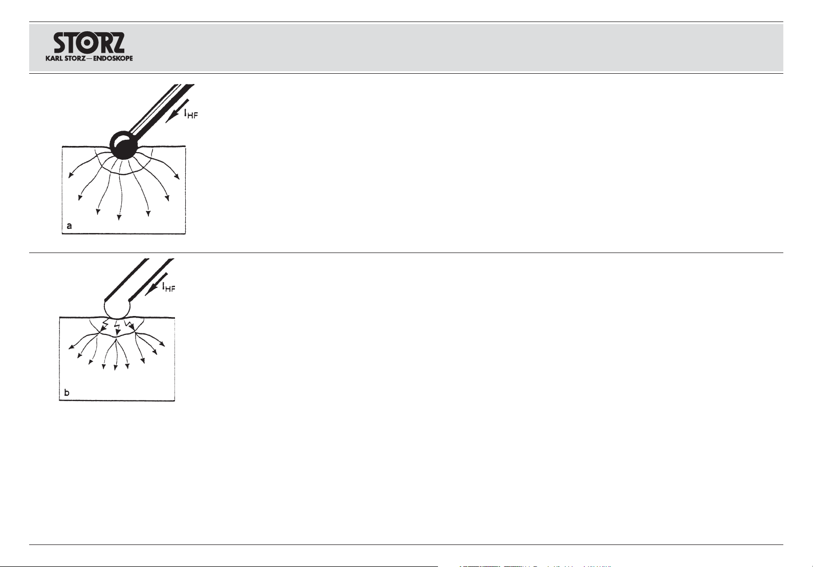
Gewebetrennung
Bei der Gewebetrennung – Schneiden – wird
die Zellflüssigkeit des Gewebes zum Verdampfen gebracht. Durch den entstehenden Dampfdruck zerreißen die Gewebezellen und der austretende Dampfdruck bewirkt eine Isolation der
Elektrode. Ist die Spannung hoch genug, so
wird der Stromfluss durch einsetzende Lichtbogenbildung zwischen der Elektrode und dem
Gewebe aufrechterhalten. Die thermische Wirkung des Stromes verursacht zum einen die
beschriebene Gewebetrennung, zum anderen
– je nach Größe des Lichtbogens – eine Oberflächenverschorfung.
Die Lichtbogenbildung setzt bei Spannungswerten um 200 Vp ein. Verwendet man Spannungen oberhalb 500 Vp, so ist eine starke Verschorfung durch die im Lichtbogen freigesetzte
Energie die Folge.
Automatische Regelkreise ermöglichen für das
Schneiden eine optimale, reproduzierbare Qualität des Schnittes, welche weitestgehend unabhängig ist von Schneidetiefe, Schnittgeschwindigkeit, Gewebewiderstand u. ä. Die Leistungsabgabe wird dabei automatisch auf die zum
Schneiden notwendige Leistung geregelt.
Separation of tissue
When separating tissue (cutting), the cell sap of
the tissue is vaporized. Due to the resulting
vapor pressure, the tissue cells tear and the
escaping vapor pressure causes the electrode
to be insulated. If the voltage is high enough,
the current flow is maintained by the commencement of arcing between the electrode and tissue.
The thermal effect of the current causes the
separation of tissue and the formation of surface
slough, depending on the size of the arc.
Arcing commences at voltage values of around
200 Vp. If voltages above 500 Vp are used, the
result is substantial formation of slough due to
the energy released in the arc.
For cutting, automatic control loops allow an
optimal, reproducible cutting quality to be
achieved, which is to the greatest possible
extent independent of cutting depth, incision
speed, tissue resistance and suchlike. Power
output is automatically adjusted to the level
required for cutting.
Sección de tejidos
En el caso de sección de tejidos (corte) se provoca la evaporación del líquido celular de los tejidos. Debido a la presión del vapor así creada, las
células de los tejidos se desgarran y la presión
procedente del vapor produce el aislamiento del
electrodo. Si la tensión es suficientemente elevada, se mantiene el flujo de corriente al provocar
la formación de un arco voltaico entre el electrodo y el tejido. El efecto térmico de la corriente
ocasiona, por una parte, la sección de tejidos
descrita y, por otra parte, según sea la intensidad
del arco voltaico, una costrificación superficial.
El arco voltaico se forma cuando los valores de
tensión alcanzan los 200 Vp. El empleo de
tensiones superiores a los 500 Vp, tiene como
consecuencia una fuerte costrificación, provocada por la energía liberada por el arco voltaico.
Los circuitos reguladores automáticos hacen posible una calidad reproducible óptima del corte,
la cual es mayormente independiente de la profundidad y velocidad de corte, de la resistencia
de los tejidos o de otras características similares.
La potencia suministrada se regula en este caso
automáticamente de acuerdo a la potencia necesaria para el corte.
3
Page 14

Allgemeines GeneralidadesGeneral information
ENDOCUT-Betrieb
(nur Gerätetyp 205225 20-010)
Ein spezielles Problem während endoskopischer
Operationen, insbesondere bei der Polypektomie
und Papillotomie, besteht darin, dass die zum
Schneiden dienenden Elektroden an langen
Zugdrähten durch enge Arbeitskanäle flexibler
Endoskope hindurchgeführt werden müssen
und der Operateur dadurch keine direkte Kontrolle über den Schneidevorgang hat. Eine kontrollierte Schnittführung ist aber gerade bei der
Polypektomie und Papillotomie eine Voraussetzung zur Vermeidung von Komplikationen. Eine
zu schnelle Schnittführung kann mangels ausreichender Koagulation der Schnittränder zu
Blutungen führen. Eine zu langsame Schnittführung kann eine thermische Schädigung beispielsweise der Darmwand verursachen.
Durch die spezielle Schnittsteuerung ENDOCUT
wird die Schnittführung automatisch derart fraktioniert, dass abwechselnd kurze, automatisch
lichtbogenkontrollierte Schnittintervalle mit definierten Pausenintervallen entstehen. Auf diese
Weise kann beispielsweise eine Polypektomieschlinge einen Polypen nicht beliebig schnell
durchschneiden. Die Schnittgeschwindigkeit
und der Koagulationsgrad der Schnittränder ist
gleichmäßiger.
ENDOCUT operation
(only on 205225 20-010)
A special problem which occurs during endoscopic operations, particularly during polypectomies and papillotomies, is that the electrodes
which are to be used for cutting must be fed
through the narrow working channels of flexible
endoscopes using long wire pulls. Therefore the
operating surgeon has no direct control over the
cutting procedure. However a controlled incision is a requirement for avoiding complications, especially during polypectomies and papillotomies. A too quickly made incision can lead
to bleeding due to insufficient coagulation of the
cut edges. An incision made too slowly can
cause thermal damage, for example, to the
intestinal wall.
Using the special ENDOCUT cutting control
system the incision is automatically fractionated
in such a way that intermittently brief, automatic
arc-controlled cutting intervals result with defined pauses. In this way, a polypectomy snare
cannot, for example, cut through a polyp at any
desired speed. The speed of incision and degree of coagulation on the cut edges is more
uniform.
Funcionamiento con ENDOCUT
(sólo tipo de aparato 205225 20-010)
Un problema específico durante las operaciones
endoscópicas, particularmente en las de polipectomía y papilotomía, deriva de que los electrodos
que sirven para cortar han de introducirse a través de angostos canales de trabajo de endoscopios flexibles mediante largos alambres y, por
ello, el operador no tiene un control directo del
proceso de corte. Precisamente el corte controlado es, sin embargo, una premisa indispensable
para evitar complicaciones al practicar la polipectomía y la papilotomía. Un corte demasiado
rápido puede producir hemorragias al no coagular suficientemente los bordes del corte practicado. Un corte demasiado lento puede, por otra
parte, producir lesiones térmicas, por ejemplo, en
las paredes intestinales.
Mediante la guía de corte ENDOCUT se fracciona automáticamente la realización del corte, de
modo que se producen intervalos cortos, durante
los que realiza automáticamente un corte controlado por arco voltaico, que se alternan con intervalos de pausa predefinidos. De este modo, se
evita, por ejemplo, cortar un pólipo con un asa de
polipectomía con rapidez arbitraria. La velocidad
de corte y el grado de coagulación de los bordes
del corte son más uniformes.
4
Page 15
Allgemeines GeneralidadesGeneral information
Gewebekoagulation
Um biologisches Gewebe zu koagulieren ist es
notwendig, dieses auf ca. 70° C zu erhitzen.
Um eine gewebetrennende Wirkung des Stromes zu vermeiden, muss die Stromzufuhr und
damit die Wärmemenge gezielt zur Denaturierung des Gewebes eingesetzt werden.
Folgende thermische Effekte in biologischem
Gewebe in Abhängigkeit von der Temperatur
lassen sich beschreiben:
bis ca. 40° C: Keine sichtbaren Zellschädigun-
gen
ab ca. 40° C: abhängig von der Stromfluss-
dauer reversible Schädigungen
ab ca. 49° C: irreversible Zellschädigungen
ab ca. 70° C: Umwandlung von Kollagenen in
Gluccose – Schrumpfung kolla-
genhaltigen Gewebes – Hämo-
stase
ab ca. 100° C: Dehydration/Desikkation: Pha-
senübergang des intra- und
extrazellulären Wassers von
flüssig in gasförmig; Klebeeffekt
der Glucose nach Dehydration;
Schrumpfung des Koagulates
nach Dehydration
ab ca. 200° C: Karbonisation und pathologi-
sche Verbrennungen 4. Grades;
Unangenehmer Geruch des
verbrannten Gewebes
Tissue coagulation
To coagulate biological tissue, it must be heated
to approx. 70 °C. To prevent the current from
causing tissue separation, the power supply,
and thereby the amount of heat, must be used
specifically to produce denaturation of the tissue.
The thermal effects which take place in biological tissue, depending on temperature, can be
described as follows:
Up to
approx. 40 °C: No visible cell damage
Approx. 40 °C Reversible cell damage
and above: depending on the duration of
current flow
Approx. 49 °C
and above: Irreversible cell damage
Approx. 70 °C Conversion of collagens
and above: into glucose – shrinking
of tissue containing
collagen – hemostasis
Approx. 100 °C Dehydration/desiccation:
and above: phase transition of intra-
cellular and extracellular
water from liquid into gas.
Adhesive effect of glucose
after dehydration. Shrinking
of the coagulum after dehydration.
Approx. 200 °C Carbonization and fourthand above: degree pathological
burns. Unpleasant odor
of burnt tissue.
Coagulación de los tejidos
Para coagular tejido biológico es necesario elevar su temperatura hasta alcanzar los 70° C
aprox. A fin de evitar el efecto separador de la
corriente sobre los tejidos, debe aplicarse selectivamente el flujo de corriente, y con ello la cantidad de calor, para obtener la desnaturalización
del tejido.
En función de la temperatura se pueden describir
los siguientes efectos térmicos sobre los tejidos
biológicos:
hasta
40° C aprox. No se aprecia deterioro celular
visible
a partir de Lesiones celulares reversibles,
40° C aprox. según la duración del flujo de
corriente
a partir de Lesiones celulares
49° C aprox. irreversibles
a partir de Transformación del colágeno en
70° C aprox. glucosa – Retracción del tejido
con contenido de colágeno –
Hemostasia
a partir de Deshidratación/desecación:
100° C aprox. fase de transición del agua in-
tra- y extrace lular del estado
líquido al gaseoso. Efecto
adhesivo de la glucosa después de la deshidratación.
Retracción del coágulo después
de la deshidratación
a partir de Carbonización y quemaduras
200° C aprox. patológicas de 4°. Odor
desagradable proveniente del
tejido quemado.
5
Page 16

Allgemeines GeneralidadesGeneral information
Aufgrund der Inhomogenität der elektrischen
und thermischen Eigenschaften im Gewebe
und der daraus ableitbaren ungleichmäßigen
Stromdichteverteilung des Gewebes steigt die
Temperatur bei Stromzufuhr unregelmäßig verteilt an.
In der Nähe der Koagulationselektrode ist die
Stromdichte und somit auch die Temperatur am
höchsten. Die Temperatur nimmt mit dem Abstand von der Elektrode sehr schnell ab, so
dass Koagulationen zunächst auf das Umfeld
der Koagulationselektrode beschränkt sind. Die
effektive Kontaktfläche zwischen Gewebe und
Koagulationselektrode hat einen entscheidenden Einfluss auf die maximal erreichbare Ausdehnung der Koagulationszone.
Wegen der Abhängigkeit der räumlichen Ausdehnung der Koagulationszone von der Stromdichteverteilung ist auch die Applikalionstechnik des HF-Stromes von Bedeutung. Hier
unterscheidet man zwischen unipolarer und
bipolarer Oberflächenapplikation, unipolarer
und bipolarer Einstichapplikation sowie unipolarer und bipolarer Greifapplikation.
Due to the inhomogeneity of the electrical and
thermal properties of tissue and the resulting
uneven current density distribution within the
tissue, the temperature rises with an irregular
distribution when power is supplied.
The current density, and thus the temperature, is
highest in the vicinity of the coagulation electrode. The temperature decreases very rapidly
with increasing distance from the electrode so
that coagulation is at first limited to the area surrounding the coagulation electrode. The effective contact area between the tissue and coagulation electrode has a decisive influence on the
maximum achievable area of the coagulation
zone.
Due to the spatial extent of the coagulation zone
being dependent on the current density distribution, the technique with which the HF current
is applied is also of importance. Here, a distinction is made between monopolar and bipolar
surface application, monopolar and bipolar
puncture application as well as monopolar and
bipolar grip application.
A causa de la falta de homogeneidad en las cualidades eléctricas y térmicas de los tejidos y de la
irregularidad derivada de ello con que se distribuye la densidad de corriente dentro de los tejidos, al fluir la corriente eléctrica la temperatura
aumenta por consiguiente de forma irregular. La
densidad de corriente y, por tanto, la temperatura
son más elevadas en las cercanías del electrodo
de coagulación. La temperatura disminuye rápidamente conforme aumenta la distancia al electrodo, por lo que los efectos coagulantes se ven
limitados al entorno del electrodo de coagulación. La superficie efectiva de contacto entre el
tejido y el electrodo de coagulación influye decisivamente en la extensión máxima alcanzable de
la zona de coagulación.
También la técnica de aplicación de la corriente
de alta frecuencia resulta significativa debido a
que la extensión física de la zona de coagulación
depende de la distribución de la densidad de
corriente. Aquí debe diferenciarse entre aplicación superficial monopolar y bipolar, aplicación
por punción monopolar y bipolar, así como aplicación por sujeción monopolar y bipolar.
Koagulationsmodi
Die räumliche Ausdehnung der Koagulationszonen ist von der Art der Energiezufuhr und der
Applikationstechnik abhängig.
Es ist zweckmäßig, zwischen 2 Koagulationsmodi zu unterscheiden.
• Soft-Koagulation
• Forcierte oder Standard-Koagulation
6
Coagulation modes
The spatial extent of the coagulation zones also
depends on the type of emergency supply and
application technique.
It is useful to differentiate between 2 coagulation
modes:
• Soft coagulation
• Forced or standard coagulation
Modos de coagulación
La extensión física de las zonas de coagulación
depende también del suministro de energía y de
la técnica aplicada.
Es conveniente distinguir entre 2 modos de
coagulación:
• Coagulación suave
• Coagulación forzada o estándar
Page 17
Allgemeines GeneralidadesGeneral information
Soft-Koagulation
Bei der Soft-Koagulation wird die Generatorspannung so gering gehalten, dass es während
des Koagulationsvorgangs zu keiner Lichtbogenbildung zwischen Elektrode und Gewebe
kommen kann. Die Soft-Koagulation ist für alle
Koagulationen empfehlenswert, bei denen
unipolare oder bipolare Koagulationselektroden
verwendet werden, die direkt mit dem zu
koagulierenden Gewebe in Kontakt gebracht
werden. Eine Karbonisation des Gewebes wird
vermieden.
Forcierte oder Standard-Koagulation
Bei der forcierten oder Standard-Koagulation
werden elektrische Lichtbogen zwischen
Koagulationselektrode und Gewebe bewusst
zugelassen, um tiefere Koagulationen zu ermöglichen als sie bei der Soft-Koagulation erreichbar sind. Dies gilt insbesondere dann,
wenn für die Koagulation nur kleinflächige Elektroden zur Verfügung stehen. Um die Gefahr
eines Schneideeffektes zu vermeiden muss
eine modulierte HF-Spannung verwendet werden. Eine Karbonisation des Gewebes muss
hierbei allerdings in Kauf genommen werden.
Ein typisches Anwendungsbeispiel ist die TUR,
bei der die Schneideelektroden auch zu Koagulationszwecken verwendet werden.
Soft coagulation
With soft coagulation, the generator voltage is
kept so low that no arcing is able to take place
between the electrode and tissue during the
coagulation process. Soft coagulation is recommended for all instances of coagulation in which
monopolar or bipolar coagulation electrodes are
used which are brought into direct contact with
the tissue that is to be coagulated. Carbonization of the tissue is avoided.
Forced or standard coagulation
With forced or standard coagulation, electric arcs
are intentionally permitted between the coagulation electrode and tissue to enable deeper
coagulations to be achieved than are possible
with soft coagulation. This particularly applies if
only small-face electrodes are available for
coagulation. To avoid the risk of a cutting effect,
a modulated HF voltage must be used. Here,
carbonization of the tissue will occur.
A typical example of applications is TUR, in
which the cutting electrodes are also used for
coagulation purposes.
Coagulación suave
En el caso de coagulación suave, la tensión del
generador se mantiene a un nivel tan bajo que
resulta imposible la formación de un arco voltaico
entre el electrodo y el tejido durante el procedimiento de coagulación. La coagulación suave es
aconsejable en todos aquellos casos en que se
empleen electrodos de coagulación monopolar o
bipolar que estén directamente en contacto con
el tejido que se va a coagular. De este modo se
evita la carbonización del tejido.
Coagulación forzada o estándar
En el caso de la coagulación forzada o estándar
se permite intencionadamente la formación del
arco voltaico entre el electrodo de coagulación y
el tejido, a fin de alcanzar efectos de coagulación
de una profundidad imposible de conseguir si se
emplea la coagulación suave. Este método se
aplica especialmente cuando sólo se dispone de
electrodos de pequeña superficie para efectuar
la coagulación. A fin de reducir el peligro de un
efecto de corte, debe aplicarse una corriente de
alta frecuencia modulada. Sin embargo, en este
caso debe contarse con una carbonización del
tejido.
Un ejemplo típico de aplicación es la resectomía
transuretral (TUR), en la que los eletrodos de corte delgados también se emplean para la coagulación.
7
Page 18
Allgemeines GeneralidadesGeneral information
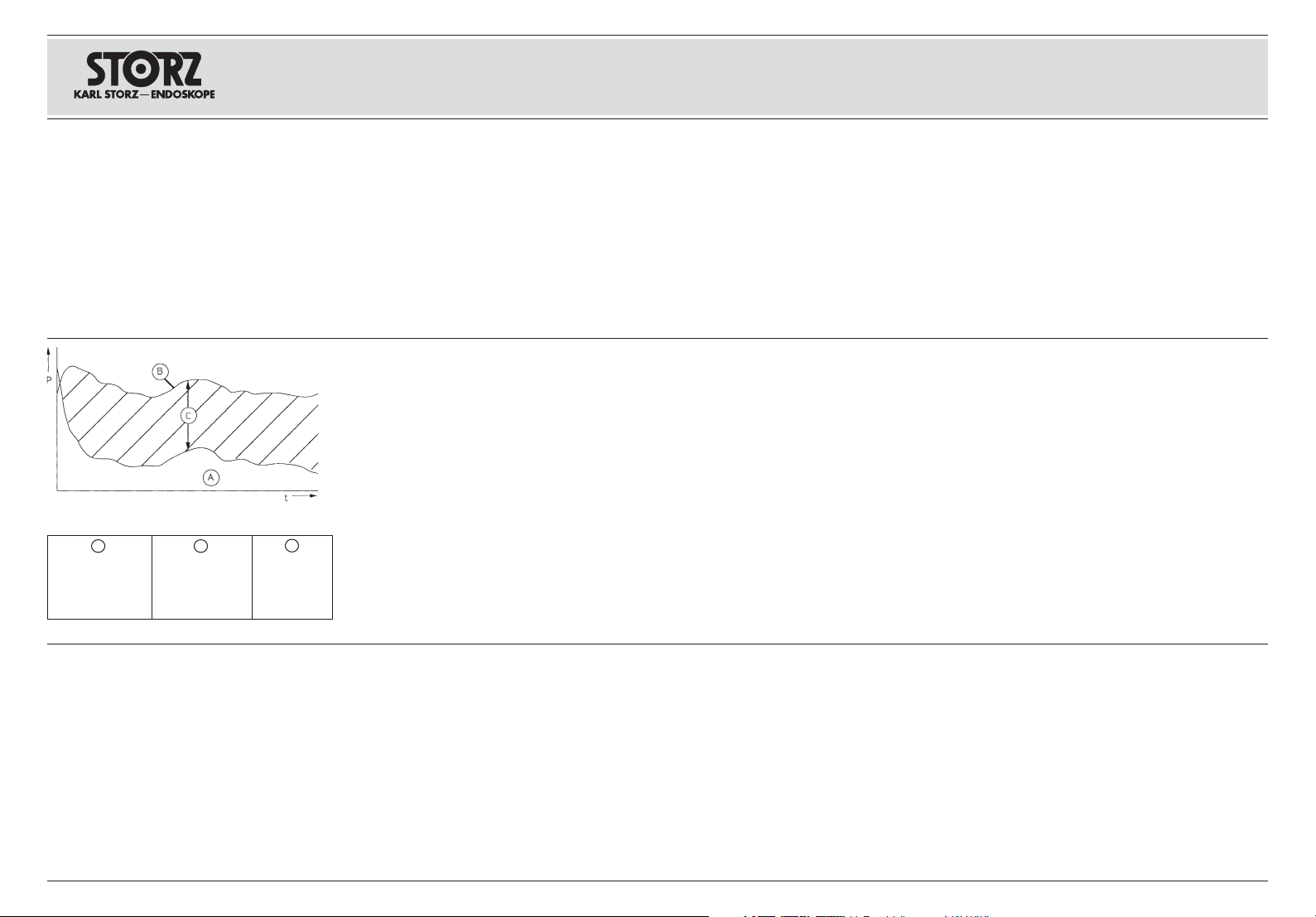
A
Zur Gewebetrennung
notwendige Leistung
Necessary power
for cutting action
Potencia necesaria para
seccionar los tejidos
B
abgegebene Leistung bei
konventionellen Geräten
power output of con-
ventional HF generators
Potencia de aparatos
convencionales
C
überschüssige
Leistung
excess power
Potencia excesiva
Das Gerät AUTOCON® 200
Die vom Anwender feststellbare Eigenschaft
einer guten Gewebetrennung (Schneiden) ist
von einer Vielzahl von verschiedenen Parametern des Gesamtsystems abhängig.
Beispielhaft seien hier genannt: Form und Abmessung der verwendeten Chirurgiesonde, die
Gewebebeschaffenheit am Operationsort, die
Eindringtiefe und Schnittgeschwindigkeit der
Chirurgiesonde, die Leitfähigkeit des verwendeteten Spülmediums, die Anbringung der neutralen Elektrode etc.
Diese zum Teil stark variablen äußeren Parameter beeinflussen bei konventionellen Hochfrequenz-Chirurgiegeräten die Eigenschaften dahingehend, dass stets die abgegebene
Leistung nachgeregelt werden müsste, oder
generell vom Bediener eine höhere Leistung
eingestellt wird. Der Leistungsüberschuss führt
aber zu einer unnötig starken Oberflächennekrotisierung und einer für den Patienten unnötig
hohen Strombelastung und den damit verbundenen Gefahren.
Abb: Leistungsabgabe (P) in Abhängigkeit von
der Zeit (t) beim Gewebeschneiden.
The AUTOCON® 200 unit
The operator bases his assessment of the quality of the tissue cutting on the various parameters of the entire system. Such parameters
include the geometry and size of the surgical
probe used, the consistency of the tissue at the
site of the operation, the penetration depth and
cutting speed of the surgical probe, the conductivity of the irrigant used, and the application
of the neutral electrode.
These ‘external’ parameters, which are extremely variable, influence the properties of conventional HF-equipment to such a degree that
the operator must constantly readjust the power
or generally set a higher power level. The excess power, however, produces severely necrotized cut edges and exposes the patient to
unnecesarily high current and the associated
risks.
Fig.: Power output (P) in relation to time (t) when
cutting tissue.
El aparato AUTOCON® 200
Las condiciones necesarias para lograr buenos
resultados en el corte (sección) de tejidos, dependen de diversos parámetros funcionales del
equipo. Sobre todo se deben mencionar: la forma
y dimensiones de las sondas quirúrgicas utilizadas, la estructura del tejido en el área operativa,
la profundidad y la velocidad de incisión de la
sonda quirúrgica, la conductibilidad del medio de
irrigación empleado, la posición del electrodo
neutro, etc.
Estos parámetros “exteriores” son muy variables,
e influyen decisivamente en las cualidades
operativas de equipos de alta frecuencia convencionales, haciendo necesario que su potencia de
funcionamiento sea postregulada constantemente, o que se tienda a utilizar una mayor potencia inicial que la requerida. Sin embargo, este
exceso de potencia produce una necrotización
superficial excesiva, y pone al paciente en contacto innecesario con fuertes cargas eléctricas,
lo que trae consigo determinados riesgos para el
paciente.
Fig.: Potencia suministrada (P) en función del
tiempo (t) al seccionar tejidos.
Das AUTOCON®200 ist mit automatischen Regelkreisen ausgestattet, mit welchen der Spitzenwert der HF-Spannung konstant geregelt
wird. Durch diese Regelung ist eine hohe Elastizität der Schnittführung bei weitgehend konstanter Schnittqualität gegeben, d.h. ohne Änderung der Einstellungen kann der Operateur
die Schneideelektroden nahezu beliebig
schnell oder langsam bzw. tief oder flach durch
das Gewebe führen, wobei die Koagulationstiefe der Schnittflächen weitgehend unabhängig
konstant bleibt.
The AUTOCON®200 is equipped with automatic
control circuitry with which the peak HF voltage
is kept constant. This control system ensures
that the type of incision is highly elastic and the
quality of the incision is largely consistent, i.e.
without altering the settings the operating surgeon can guide the cutting electrode the tissue
at virtually any depth, whereby the coagulation
depth of the cut surfaces remains largely constant irrespectively.
El AUTOCON
automáticos de regulación que ajustan constantemente el valor máximo de la tensión de alta frecuencia. Esta regulación permite una elevada
elasticidad de la guía de corte manteniendo una
calidad de corte casi constante, por lo que, sin
necesidad de modificar los ajustes, el operador
puede dirigir los electrodos de corte a través del
tejido, seleccionando casi libremente la velocidad o profundidad que estime oportunas, mientras que la profundidad de coagulación de las
superficies de corte, en gran parte independiente
®
200 está equipado con circuitos
de ello, permanece constante.
8
Page 19

Allgemeines GeneralidadesGeneral information
Das Hochfrequenz-Chirurgiegerät AUTO-
®
200 ist ein universell einsetzbares Gerät,
CON
das die präzise Einstellung verschiedener
Schnitt- und Koagulationsqualitäten sowie die
sichere Reproduzierbarkeit dieser Einstellungen
ermöglicht. Durch automatische Steuerung und
Regelung der HF-Spannung wird in jeder Phase
des Schnitts genau die HF-Spannung und Intensität zur Verfügung gestellt, die für das Erreichen der gewünschten Schnittqualität notwendig ist.
Das AUTOCON® 200 ermöglicht unipolare
Schnitte mit Spannungskonstantregelung sowie
– als Sonderausstattung – unipolare Schnitte in
der ENDOCUT-Einstellung. Für Koagulationen
stehen 3 verschiedene, 2 unipolare und 1 bipolarer Koagulationsmodus zur Verfügung. Der
bipolare Koagulationsmodus ermöglicht zusätzlich den Betrieb mit Autostart-Funktion.
In Verbindung mit der automatischen Steuerung
und Regelung der Schnitt- und Koagulationsqualität bieten die verschiedenen Sicherheitseinrichtungen des Gerätes eine außerordentlich
hohe Anwender- und Patientensicherheit. Eine
Fehlerdokumentationseinrichtung sowie Software-unterstützte Testprogramme sorgen für
einfachen und schnellen Service.
The AUTOCON® 200 HF surgical unit is a universally applicable unit which permits the precise setting of various incision and coagulation
qualities as well as reliable reproducibility of
these settings. Due to automatic open-loop and
closed-loop control of the HF voltage, the HF
voltage and intensity required for achieving the
desired incision quality are provided in each
phase of the incision.
The AUTOCON® 200 permits monopolar incisions with voltage stability control and – as an
optional extra – monopolar incisions in the
ENDOCUT setting. 3 different modes are available for coagulation, 2 monopolar and 1 bipolar.
The bipolar coagulation mode additionally
permits operation with the Autostart function.
In conjunction with automatic open-loop and
closed-loop control of incision and coagulation
quality, the instrument’s various safety devices
provide an exceptionally high level of user and
patient safety. An error documentation facility
as well as software-supported test programs
ensure easy and rapid servicing.
El aparato quirúrgico de alta frecuencia
AUTOCON
®
200 es de aplicación universal, haciendo posible el ajuste preciso de diversos tipos
de corte y coagulación, así como su segura
reproducibilidad. Mediante el control automático
y regulación de la tensión de alta frecuencia se
dispone en cada fase de corte exactamente de la
tensión e intensidad que se necesitan para obtener la intervención deseada.
El AUTOCON® 200 hace posibles cortes monopolares con regulación constante de la tensión y
cortes monopolares en la función ENDOCUT
(equipamiento especial). Para la coagulación se
dispone de 3 modos diferentes: 2 modos monopolares y un modo bipolar de coagulación. El
modo de coagulación bipolar hace posible la
función con Autostart.
En relación con el control automático y el ajuste
de los tipos de corte y coagulación, ofrecen los
diversos dispositivos de seguridad del aparato
una extraordinaria seguridad de funcionamiento,
tanto para el operador, como para el paciente. La
documentación de fallas, así como los programas
de verificación del software, hacen posible un
mantenimiento sencillo y rápido.
9
Page 20
Sicherheitshinweise Safety instructions Instrucciones de seguridad
Warn- und Vorsichtshinweise
Bitte lesen Sie diese Gebrauchsanweisung
sorgfältig durch, und beachten Sie die Anweisungen genau. Die Bezeichnungen Warnung,
Vorsicht und Hinweis haben spezielle Bedeutungen. Wo immer sie in der Gebrauchsanweisung verwendet werden, sollte der nachfolgende Text genau gelesen werden, um einen
sicheren und effizienten Betrieb des Gerätes zu
gewährleisten. Zur deutlicheren Hervorhebung
steht den Bezeichnungen Warnung und
sicht zusätzlich ein Piktogramm voran.
Definitionen
Warnung: Warnung macht auf eine Ge-
fährdung des Patienten oder des Arztes
aufmerksam. Die Nichtbeachtung einer
Warnung kann Verletzungen des Patienten oder des Arztes zur Folge haben.
Vorsicht: Vorsicht macht darauf auf-
merksam, dass bestimmte Wartungsoder Sicherheitsmaßnahmen zu treffen
sind, um eine Beschädigung des Gerätes zu vermeiden.
Hinweis: Hinweise enthalten spezielle Informationen zur Bedienung des Gerätes, oder sie erklären wichtige Informationen.
Vor-
Warnings and cautions
Please read this manual and follow its instructions carefully. The words Warning, Caution,
and Note convey special meanings. Wherever
they are used in this manual, the accompanying
text should be read carefully to ensure the safe
and effective operation of this product. To make
the words Warning and Caution stand out more
clearly, they are accompanied by a pictogram.
Definitions
Warning: A Warning indicates that the
personal safety of the patient or physician may be involved. Disregarding a
Warning could result in injury to the
patient or physician.
Caution: A Caution indicates that
particular service procedures or
precautions must be followed to avoid
possible damage to the product.
Note: A Note indicates special information
about operating the product, or clarifies important information.
Indicaciones de alarma y
advertencia
Lea este manual y siga las instrucciones minuciosamente. Los términos Cuidado, Advertencia y
Nota tienen significados muy especiales. Cuando aparezcan en alguna parte de este Manual,
revise esa sección cuidadosamente para asegurar la operación inocua y eficaz de este producto.
Para destacar más claramente los términos Cui-
dado y Advertencia, los mismos están precedidos por un pictograma adicional.
Definiciones
Cuidado: El término Cuidado llama la
atención sobre una situación de peligro
para el paciente o para el médico. La
inobservancia de este aviso podría conllevar lesiones para el paciente o para el
médico.
Advertencia: El término Advertencia
llama la atención sobre determinadas
medidas de mantenimiento o de seguridad que han de llevarse a cabo a fin de
evitar el deterioro del aparato.
Nota: Los párrafos denominados con el término
Nota contienen informaciones especiales para el
manejo del equipo o aclaran informaciones importantes.
10
Warnung: Lesen Sie diese Gebrauchsanwei-
sung genau durch, bevor Sie das Gerät in Betrieb nehmen. Lesen Sie besonders das Kapitel
Sicherheitshinweise aufmerksam durch, um
Gefährdungen Ihrer Patienten, Ihres Personals
sowie Ihrer eigenen Person zu vermeiden.
Hinweis: Beschädigungen des Gerätes, die
aufgrund von Fehlbedienungen entstehen, fallen nicht unter die Gewährleistungsansprüche.
Warnung: Die elektrischen Installationen des
Operationssaals müssen die Anforderungen
der geltenden IEC-Normen erfüllen.
Warnung: Gerät außerhalb der Reichweite von
Patienten aufstellen.
Warning: Read this instruction manual thorough-
ly and be familiar with its contents prior to using
this equipment. Before using the unit, read the
following safety instructions carefully to avoid putting your patients, personnel or yourself at risk.
Note: Any damage to the unit resulting from in-
correct operation is not covered by the manufacturer’s warranty.
Warning: The electrical installation of the
operating room must comply with the applicable
IEC requirements.
Warning: Keep out of reach of patients.
Cuidado: Lea detenidamente este Manual de ins-
trucciones antes de usar el equipo. Lea con especial atención el capítulo referente a las instrucciones de seguridad, a fin de evitar poner en peligro a sus pacientes, a su personal y a usted
mismo.
Nota: Los deterioros del equipo derivados del
manejo incorrecto del mismo, no serán reconocidos como derechos de garantía.
Cuidado: La instalación eléctrica en el quirófano
debe cumplir con los requisitos CEI correspondientes.
Cuidado: Mantenga el equipo lejos del alcance
de los pacientes.
Page 21

Sicherheitshinweise Safety instructions Instrucciones de seguridad
Warn- und Vorsichtshinweise Indicaciones de alarma y advertencia
Warnings and cautions
Warnung: Die Gebrauchsanweisungen und die
Schnittstellenspezifikationen der in Kombination
verwendeten Medizinprodukte und/oder Systemkomponenten sind genauestens zu beachten.
Warnung: Eine sicherheitstechnische Unbe-
denklichkeit bei Kombinationen von Medizinprodukten ist nur dann gegeben, wenn
• diese in den jeweiligen Gebrauchsanweisungen als solche ausgewiesen sind oder
• die Zweckbestimmung und die Schnittstellenspezifikation der in der Kombination verwendeten Produkte dies zulässt.
Warnung: Das Gerät ist nur dann zuverlässig
geerdet, wenn es an einer einwandfrei installierten Schutzkontakt-Steckdose angeschlossen
ist. Stecker und Kabel routinemäßig prüfen und
bei Beschädigung nicht verwenden.
Warnung: Prüfen Sie dieses Gerät vor jeder
Anwendung auf seine Funktionsfähigkeit. Bei
offensichtlichen Schäden darf das Gerät nicht
verwendet werden.
Warnung: Bei Verwendung zündfähiger Narko-
segase in der unmittelbaren Umgebung des
Gerätes besteht Explosionsgefahr.
Warnung: Vor sämtlichen Wartungsarbeiten am
Gerät ist die Netzverbindung zu trennen.
Warnung: Gerät nicht öffnen! Gefahr eines elek-
trischen Schlages. Lassen Sie Service-Arbeiten
nur durch den Hersteller oder durch vom Hersteller autorisiertes Personal durchführen
(vgl. Medizinprodukte-Betreiberverordnung §4).
Jedes Öffnen des Gerätes durch unautorisierte
Personen führt zum Erlöschen der Garantie.
Warnung: Das Berühren von nichtisolierten Instrumenten durch die HF-aktivierte Elektrode
kann zu unbeabsichtigten Verbrennungen führen. Daher empfehlen wir die Benutzung Isolierter Instrumente im Umfeld der Aktiven Elektrode.
Warnung: Vermeiden Sie den Stromfluss über
Gewebebrücken. Die entstehenden Stromkonzentrationen am Fußpunkt zum gesunden
Gewebe können möglicherweise Verbrennungen hervorrufen.
Warnung: Verwenden Sie normgerechte Endoskope mit isoliertem Okulartrichter, um mögliche
kapazitive Leckströme zum Anwender oder zum
angekoppelten Kamerasystem zu vermeiden.
Warning: The instructions and interface specifi-
cations for medical devices and/or system components used in combination must be observed
precisely.
Warning: Combinations of medical devices are
only assured to be safe if
• they are identified as such in the respective
instruction manuals or
• the intended purpose and interface specifications of the devices used in combination permit this.
Warning: Grounding reliability can only be
achieved when the equipment is connected to a
“Hospital Only” or “Hospital Grade” outlet (i.e.,
approved for use in an operating room environment). Routinely inspect electrical plug and
cord. Do not use if inspection reveals damage.
Warning: Test this equipment prior to each sur-
gical procedure to ensure that it functions correctly. The unit should not be used if any damage is evident.
Warning: Risk of explosion if used in the pres-
ence of flammable anesthetics.
Warning: Always unplug the unit before carry-
ing out any maintenance work on it (e.g. cleaning).
Warning: To avoid the risk of electrical shock,
do not open the unit. Refer servicing to the manufacturer or to qualified personnel. Removal of
covers by unauthorized personnel will void the
equipment’s warranty.
Warning: Contact with noninsulated instruments
by the active high frequency electrode can lead
to unintentional burns. We therefore recommend
using insulated instruments in the vicinity of the
active electrode.
Warning: Avoid currents flowing via tissue
bridges. The resulting current concentrations at
the base adjoining healthy tissue may cause
burns.
Warning: Use standard-compliant endoscopes
with an insulated eyepiece to reduce the risk of
capacitive leakage currents flowing to the user
or to the attached camera system.
Cuidado: Deben observarse con la máxima
exactitud los Manuales de instrucciones y las especificaciones de interfaz de los productos médicos y/o componentes de sistema utilizados en
combinaciones entre sí.
Cuidado: Una aplicación técnica y de seguridad
sin objeciones en el caso de combinaciones de
productos médicos puede darse únicamente si
• los mismos están indicados expresamente
como tales en los Manuales de instrucciones
respectivos, o
• si la determinación de aplicación y la especificación de interfaz de los productos utilizados
en combinación lo permiten.
Cuidado: La conexión a tierra de este equipo es
únicamente fiable si se encuentra conectado a un
enchufe con puesta a tierra debidamente instalado. Controle el cable y el enchufe con regularidad y no los utilice si están deteriorados.
Cuidado: Compruebe la capacidad de funciona-
miento de este equipo antes de cada utilización.
No siga utilizando el instrumento si se comprueban deterioros evidentes.
Cuidado: Existe peligro de explosión si se em-
plean gases narcóticos inflamables en las inmediaciones del equipo.
Cuidado: Antes de efectuar cualquier tarea de
mantenimiento, desconecte el equipo de la red..
Cuidado: ¡No abrir! Peligro de descarga eléctri-
ca. Los trabajos de servicio técnico deben ser
realizados únicamente por el fabricante ó personal autorizado. Si el equipo es abierto por personas no autorizadas, esto implica la extinción de
los derechos de garantía.
Cuidado: Tocar instrumentos no aislados con el electrodo de AF activado puede producir quemaduras.
Por ello recomendamos la utilización de instrumentos aislados en el entorno del electrodo activo.
Cuidado: Evite el flujo de corriente a través de
puentes de tejido. Las concentraciones de corrientes resultantes en la base del tejido sano
pueden producir quemaduras.
Cuidado: Utilice endoscopios normalizados con
ocular aislado, a fin de evitar posibles corrientes
capacitivas de fuga hacia el usuario o hacia el
sistema de cámara acoplado.
11
Page 22

Sicherheitshinweise Safety instructions Instrucciones de seguridad
Warn- und Vorsichtshinweise Indicaciones de alarma y advertenciaWarnings and cautions
Warnung: Beachten Sie immer die maximal zulässige HF-Spitzenspannung für den Betrieb
der Instrumente. Eine Missachtung der max.
zulässigen HF-Spitzenspannung für den Betrieb von verwendbarem Zubehör zu HF-Generatoren, kann zur Zerstörung der Isolation und
dadurch zu möglichen Verbrennungen an den
Kontaktstellen des Instrumentes zum Patienten
oder Anwender führen.
Warnung: Der während des Einsatzes des HFChirurgiegerätes an der Elektrode entstehende
Lichtbogen kann die Funktion anderer elektrischer Geräte beeinträchtigen.
Warnung: Bei gleichzeitiger Verwendung von
HF-Chirurgie und physiologischen Überwachungsgeräten an einem Patienten sollte jegliche
Überwachungselektrode möglichst weit von aktiver und neutraler Elektrode des HF-Chirurgiegerätes entfernt angebracht werden; die Verwendung von Nadelelektroden für die
Überwachung ist zu vermeiden. In jedem Fall
werden Überwachungselektroden empfohlen,
die Vorrichtungen zur Begrenzung des hochfrequenten Stromes enthalten.
Warnung: Eine kurzgeschlossene zweiflächige
Neutralelektrode schließt eine Überwachung aus.
Warnung: Das Gerät darf nur innerhalb der spezifizierten Umweltbedingungen betrieben werden.
Warnung: Achten Sie bei ihrem Gerät auf ausreichende Luftzirkulation.
Warnung: Patientenkontakt mit metallischen
geerdeten Teilen ist zu verhindern.
Warnung: Im Falle eines plötzlichen Leistungsverlustes ist vor der Erhöhung der Leistungsabgabe der korrekte Sitz der Neutralelektrode sicher zu stellen.
Warnung: Durch niederfrequente elektrische
Ströme können während der Hochfrequenzchirurgie Nerven und Muskeln des Patienten
gereizt werden.
Warnung: Patienten mit Herzschrittmacher sind
einer besonders sorgfältigen Behandlung zu
unterziehen. Herzschrittmacher können durch
Hochfrequenzenergie gestört werden. Herstellerangaben für Herzschrittmacher sind streng
zu beachten.
Warning: Please always observe the maximum
permitted high frequency peak voltage for operation of the instruments. Failure to observe the
maximum permissible high frequency peak voltage for the operation of endoscopic accessories to high frequency generators can lead to
destruction of the insulation and thus to possible burns at the contact points of the instrument to the patient or user.
Warning: The arc produced at the electrode
during operation of the high frequency surgical
device can impair the function of other electrical
devices.
Warning: During simultaneous use of high frequency surgery and physiological monitoring
equipment on a patient, every monitoring electrode should be positioned as far away as possible from the active and neutral electrodes of
the high frequency surgical device. Needle
electrodes for monitoring are not recommended.
In all cases monitoring electrodes which contain
devices for limiting the high frequency current
are recommended.
Warning: A double-faced neutral electrode that
has short-circuited precludes monitoring.
Warning: The unit may only be operated under
the environmental conditions specified.
Warning: Please ensure that there is sufficient
air circulation for your unit.
Warning: If liquid enters the unit, it must be
given enough time to evaporate.
Warning: Patient contact with grounded metal
parts must be avoided.
Warning: In the event of a sudden power loss,
check that the neutral electrode is correctly positioned before increasing the power output.
Warning: Due to low-frequency electric currents, nerves and muscles of the patient can be
stimulated during HF surgery.
Warning: Patients with heart pacemakers must
be treated with special care. High frequency energy can interfere with heart pacemakers. The
pacemaker manufacturer's instructions must be
strictly followed.
Cuidado: Tenga en cuenta siempre la tensión
máxima de cresta permitida de AF para el funcionamiento de los instrumentos. La desatención del
cumplimiento de la tensión máxima de cresta permitida de AF, para el funcionamiento de accesorios endoscópicos para generadores de AF, puede causar la destrucción del aislamiento y con
ello producir quemaduras al paciente o al usuario
en los puntos de contacto del instrumento.
Cuidado: Los arcos voltaicos que se producen
en el electrodo durante la aplicación del aparato
quirúrgico de AF pueden menoscabar el funcionamiento de otros aparatos eléctricos.
Cuidado: Al utilizar simultáneamente cirugía de AF
y aparatos de control fisiológico en un paciente, se
debería situar cualquier electrodo de control lo más
lejos posible de electrodos activos y neutrales del
aparato quirúrgico de AF. Debe evitarse el uso de
electrodos de aguja para el monitoreo. En todos
los casos se recomiendan electrodos de control,
que contengan dispositivos para la limitación de
la corriente de alta frecuencia.
Cuidado: Un electrodo neutro bifacial cortocircuitado excluye un monitoreo.
Cuidado: El aparato sólo puede ser utilizado dentro de las condiciones ambientales especificadas.
Cuidado: Tenga en cuenta una suficiente circulación de aire en su aparato.
Cuidado: En caso de haber ingresado líquido en
el equipo, debe preverse un tiempo suficiente
para su evaporación.
Cuidado: Debe evitarse el contacto del paciente
con piezas metálicas puestas a tierra.
Cuidado: En caso de una repentina pérdida de
potencia, antes de aumentar la emisión de potencia debe comprobarse el asiento correcto del
electrodo neutro.
Cuidado: Debido a la presencia de corrientes
eléctricas de baja frecuencia, puede producirse
una estimulación de los músculos y nervios del
paciente durante la cirugía de alta frecuencia.
Cuidado: Los pacientes con marcapasos deben
tratarse con particular cuidado. Los marcapasos
pueden resultar deteriorados por la energía de
alta frecuencia. Observe estrictamente las indicaciones del fabricante del marcapasos.
12
Page 23
Sicherheitshinweise Safety instructions Instrucciones de seguridad
Anwendung von mehreren HF-Geräten an
einem Patienten
Warnung: Nur Geräte mit „floatenden” F Anwendungsteilen verwenden. Jedes Gerät immer
mit einer eigenen Neutralelektrode betreiben.
Interaktion von Hochfrequenz-Stromkreisen vermeiden, d.h. auf räumliche Trennung achten
(z.B. Anwendung Kopfende, Fußende, Körpermitte, keine „Kreuzung“ der Stromwege von
aktiver zu neutraler Elektrode).
Alle Geräte entsprechend den Hinweisen in der
jeweiligen Gebrauchsanweisung betreiben.
Verletzung durch unsachgemäß vorgewählte
HF-Parameter
Warnung: Stets eine für den jeweils angestrebten Eingriff geeignete Hochfrequenz-Ausgangsleistung vorwählen, um Folgendes zu vermeiden:
• eine mögliche thermische Tiefenwirkung im
Gewebe durch eine zu hohe Leistungs- und
Effekteinstellung
• eine unzureichende Koagulation durch eine
zu geringe Leistungseinstellung, die starke
Blutungen zur Folge haben kann.
Warnung: Konzentrationen explosiver Gase,
die im Bereich des hochfrequenzchirurgischen
Eingriffs vorhanden sein können, sind zu vermeiden. Folgende Situationen sind u.a.
besonders zu beachten:
Bei nicht vorbereiteten Patienten können im
Gastrointestinaltrakt manchmal zündfähige
Gase vorhanden sein. Durch bestimmte Substanzen für die Vorbereitung des unteren
Verdauungstraktes kann die Erzeugung von
Methan gefördert werden. Dies gilt im besonderen Maße für die Koloskopie, ist aber auch vom
oberen Gastrointestinaltrakt berichtet worden.
Weiterhin ist bei der transurethralen Resektion
der Prostata beobachtet worden, dass sich in
der Blase oberhalb der Spülflüssigkeit Wasserstoff ansammeln kann, dies besonders dann,
wenn mit starkem Lichtbogen gearbeitet wird.
Das Arbeiten in explosiven Gasgemischen kann
zu einer Verpuffung/Explosion führen.
Vorsicht: Das Gerät nur mit der auf dem Typen-
schild angegebenen Spannung betreiben.
Vorsicht: Nur Sicherungen mit den angegebe-
nen Werten verwenden.
Use of several HF units on one patient
Warning: Only use units with ‘floating’ application parts. Always operate each unit with its own
neutral electrode.
Avoid high frequency electric circuits, i.e. ensure adequate spacing (e.g. at the top, bottom,
in the center, no switching of active to neutral
electrodes).
All units should be operated according to the
instructions provided in the respective
instruction manuals.
Injury due to incorrect preselected high
frequency parameters
Warning: Always select a high frequency output
power setting suitable for the particular
procedure in question in order to avoid:
• thermal invasion of the tissue, which can be
caused by too high a power or effect setting;
• insufficient coagulation resulting in excessive
bleeding, which can be caused by too low a
power setting.
Warning: Avoid explosive gas concentrations
that may be present in the area where a high
frequency surgical procedure is being conducted. The following situations, among others,
must be taken into consideration:
Gas which may support combustion is sometimes present in the gastrointestinal tract of an
unprepared patient. Certain substances used
for the preparation of the lower Gl tract can enhance methane production. This is particularly
relevant in colonoscopy, but has also been recorded in the upper Gl tract. In addition, during
transurethral resection of the prostate, it has
been recorded that hydrogen can accumulate in
the bladder above the irrigation solution, this is
particularly true when a strong arc is used.
Working with explosive gas mixtures may lead
to deflagration/explosion.
Caution: Only operate the unit with the voltage
stated on the unit's identification plate.
Caution: Use only fuses of the correct rating.
Utilización de varios aparatos de AF en un
paciente
Cuidado: Utilice sólo aparatos con piezas de
aplicación “flotantes” F. Utilice cada aparato con
un electrodo neutro propio.
Evite la interacción de circuitos eléctricos de alta
frecuencia, es decir, preste atención a que haya
suficiente espacio entre ellos (p. ej., aplicación
en la cabecera, el extremo de los pies, el centro
del cuerpo, sin “cruzamiento” del recorrido de la
corriente del electrodo activo al electrodo neutro).
Utilice los aparatos conforme a las indicaciones
de los Manuales de instrucciones respectivos.
Lesiones por parámetros de AF
preseleccionados de forma inadecuada
Cuidado: Preseleccione siempre una potencia de
salida de alta frecuencia apropiada para la intervención correspondiente, con el fin de evitar:
• una excesiva profundización térmica en el tejido, debido a ajustes de potencia y de efecto
demasiado elevados
• una coagulación insuficiente debido a un ajuste de potencia demasiado reducido, lo que
puede producir fuertes hemorragias.
Cuidado: Se debe evitar la concentración de gases explosivos, que puedan encontrarse en la
zona de la intervención de alta frecuencia. Se deben tener en cuenta especialmente las siguientes
situaciones:
En pacientes no preparados pueden hallarse a
veces gases inflamables en el tracto gastrointestinal. Mediante ciertas sustancias para la preparación del tracto digestivo inferior se puede favorecer la producción de metano. Ello es de relevancia sobre todo en la colonoscopia, pero
también se puede producir en el tracto gastrointestinal superior. En la resección transuretral de la
próstata se ha observado que se puede almacenar hidrógeno en la vejiga por encima del líquido
de irrigación, sobre todo cuando se trabaja con
un fuerte arco voltaico.
El trabajo con mezclas de gases explosivos puede
producir una explosión/deflagración.
Advertencia: Utilice el aparato sólo con la tensión indicada en la placa de características.
Advertencia: Utilice sólo fusibles con las características indicadas.
13
Page 24

Sicherheitshinweise Safety instructions Instrucciones de seguridad
Vorsicht: Ein Eindringen von Flüssigkeit in das
Gehäuse ist unbedingt zu vermeiden. Keine
Flüssigkeit auf oder über dem Gerät lagern.
Es ist ebenfalls darauf zu achten, dass keine
Flüssigkeitsbehälter oder –schläuche in der
Nähe des Gerätes platziert sind.
Ist trotz aller Vorsichtsmaßnahmen Flüssigkeit in
das Gerät eingedrungen, ist ausreichend Zeit
zum Verdunsten vorzusehen (ebenfalls bei Bildung von Kondenswasser).
Vorsicht: Der Signalein- und Signalausgang
dieses Gerätes wurde vom Hersteller ausschließlich zum Anschluss an Geräte vorgesehen, die die Norm IEC 60601-1 erfüllen.
Vorsicht: Bei der Reinigung des Gerätes und
bei der Aufbereitung/Sterilisation von Gerätezubehör unbedingt die Gebrauchsanweisung
beachten.
Hinweis: Bei Zubehör zu HF-Generatoren ist
auf die maximal zulässige HF-Spitzenspannung
zu achten. Beachten Sie die mitgelieferten Beipackzettel oder Gebrauchsanweisungen, um
Schäden am Material zu verhindern.
Hinweis: Hochfrequenzkabel, Anschlusskabel
zur Neutralelektrode und endoskopisch verwendetes Zubehör regelmäßig auf Schäden der
Isolierung prüfen.
Hinweis: Bei der Entsorgung von Zubehör sind
die länderspezifischen Vorschriften/Gesetze zu
beachten.
Hinweis: In der Presse wurde verschiedentlich
über eine mögliche Störbeeinflussung von Medizinprodukten durch Mobiltelefone (Handys)
berichtet, die im Umfeld von Medizinprodukten
betrieben wurden. Wir empfehlen deshalb, im
Umfeld von Medizinprodukten das Betreiben
von Mobiltelefonen zu vermeiden bzw. zu untersagen und dies durch entsprechende Hinweise
deutlich zu machen.
Caution: Avoid allowing liquids to enter the unit.
Do not store liquids on or above the unit. It must
also be ensured that no liquid bottles or tubing
are placed near the unit.
If liquid enters the unit, despite the precautions,
sufficient time should be planned for evaporation (this also applies for the formation of
condensation).
Caution: The signal input and signal output
parts of this equipment are designated by the
manufacturer for exclusive connection to equipment which complies with IEC 60601-1.
Caution: It is essential to follow the instruction
manual closely when cleaning the unit and
preparing/sterilizing unit accessories.
Note: In the case of HF generator accessories,
attention must be paid to the maximum HF peak
voltage allowed. Please observe the instruction
leaflet or instruction manuals provided to prevent damage to the material.
Note: Inspect high frequency cord, the connecting cable to the neutral electrode and endoscopic accessories regularly for damage to the
insulation.
Note: Make certain to observe national regula-
tions/laws regarding disposal.
: :
Note
: There have been various reports in the
: :
press about possible interference to medical
instruments caused by nearby mobile telephones. We therefore recommend avoiding or
prohibiting the use of mobile telephones near
medical devices and pointing this out by appropriate signs.
Advertencia: Se debe evitar el ingreso de líquidos en la unidad. No se debe almacenar líquido
en o sobre el aparato. También se debe tener en
cuenta que no haya recipientes o tubos con líquido en las inmediaciones del aparato.
Si, a pesar de todas las precauciones tomadas,
se ha infiltrado líquido en el equipo, debe preverse un tiempo suficiente para su evaporación (lo
mismo ocurre en caso de formación de agua por
condensación).
Advertencia: La entrada/salida de señales de
este aparato ha sido prevista por el fabricante exclusivamente para la conexión en aparatos que
cumplan la norma CEI 60601-1.
Advertencia: Al efectuar la limpieza del aparato
y la preparación/esterilización de accesorios de
aparatos observe imprescindiblemente las indicaciones contenidas en el Manual de instrucciones.
Nota: En los accesorios para generadores de AF
se debe tener en cuenta la máxima tensión de
cresta de AF permitida. Observe las indicaciones
contenidas en el prospecto adjunto o en el Manual de instrucciones, a fin de evitar deterioros en
el material.
Nota: Verifique regularmente si existen deterioros
en el aislamiento del cable de alta frecuencia, del
cable de conexión al electrodo neutro y de los
accesorios utilizados endoscópicamente.
Nota: Deberá observarse la legislación vigente,
tanto local como estatal, en materia de gestión de
residuos.
Nota: En la prensa se ha hecho repetidamente
mención de las posibles interferencias producidas por teléfonos móviles en la función de aparatos médicos, si dichos teléfonos se utilizan en sus
inmediaciones. Por ello recomendamos evitar o
prohibir el uso de teléfonos móviles en las inmediaciones de aparatos médicos, indicándolo claramente mediante la señalización pertinente.
14
Page 25

Sicherheitshinweise Safety instructions Instrucciones de seguridad
Bitte lesen Sie diese Sicherheitshinweise vor
der Benutzung des Gerätes aufmerksam durch.
Machen Sie sich vor der ersten Anwendung des
Gerätes am Patienten unbedingt mit der Funktionsweise und Bedienung des Gerätes vertraut.
Bestimmungsgemäße
Verwendung
Das AUTOCON® 200 ist ein HochfrequenzChirurgiegerät für unipolares Schneiden sowie
unipolares und bipolares Koagulieren mit dazu
geeigneten Instrumenten.
Die Verwendung des Gerätes anders als oben
bestimmt ist aus Sicherheitsgründen nicht
zulässig.
Das AUTOCON® 200 darf nur mit Zubehör verwendet werden, das von KARL STORZ als für
das Gerät geeignet bezeichnet wird oder dessen sicherheitstechnisch unbedenkliche Verwendungsfähigkeit nachgewiesen ist.
Eigenmächtige Umbauten oder Veränderungen
des Gerätes sind aus Sicherheitsgründen untersagt.
Please read these safety instructions carefully
before using the unit.
Before using the unit on the patient it is imperative that you be acquainted with how the unit
operates and is controlled.
Intended use
The AUTOCON® 200 is a high frequency surgical
unit for monopolar cutting as well as monopolar
and bipolar coagulation with suitable instruments.
Use of the unit in fields other than those indicated above is not allowed for safety reasons.
The AUTOCON® 200 may only be used with
accessories which have been designated by
KARL STORZ as suitable for the unit or the safe
use of which is proven.
Unauthorized conversions or modifications to
the unit are not allowed for safety reasons.
Le rogamos leer con la mayor atención estas
instrucciones de seguridad antes de emplear el
equipo.
Familiarícese a fondo con los modos de funcionamiento y el manejo del equipo antes de emplearlo por primera vez con un paciente.
Empleo previsto
El AUTOCON® 200 es un aparato quirúrgico de
alta frecuencia diseñado para realizar cortes
monopolares, así como coagulaciones
monopolares y bipolares con instrumentos
adecuados para tal fin.
Por razones de seguridad, no es admisible la
utilización del equipo en otros campos de aplicación diferentes de los previstos.
®
El AUTOCON
accesorios que la empresa KARL STORZ haya
calificado como adecuados para los equipos, o
si se ha comprobado su idoneidad de aplicación
técnica y de seguridad sin que exista objeción
alguna.
Por razones de seguridad, está prohibido efectuar
reformas o cambios arbitrarios en los equipos.
200 sólo puede emplearse con
15
Qualifikation des Anwenders
Das AUTOCON® 200 darf nur von Ärzten und
medizinischem Assistenzpersonal angewendet
werden, die über eine entsprechende fachliche
Qualifikation verfügen und am Gerät eingewiesen sind. Die Einweisung darf nur durch solche
Personen erfolgen, die aufgrund ihrer Kenntnisse dazu geeignet sind.
Die zuständige Gebietsvertretung oder der zuständige KARL STORZ Vertreter steht für die
Einweisung bei Ihnen zur Verfügung.
User qualification
The AUTOCON® 200 may only be used by physicians and medical assistants who have a corresponding specialized qualification and who
have been instructed in the use of the instrument. Such instruction should only be provided
by persons equipped to do so on the basis of
their skills.
Your local representative or responsible
KARL STORZ member of staff is available to
provide training on your premises.
Cualificación del usuario
El AUTOCON® 200 sólo puede ser empleado por
médicos y personal de asistencia médica que
dispongan de una cualificación profesional adecuada y que hayan recibido instrucciones sobre
la utilización del aparato. Unicamente personas
que por sus conocimientos estén capacitadas
para ello deben encargarse de impartir la instrucción en el manejo del equipo.
Su representante local o el responsable correspondiente de KARL STORZ están gustosamente
a su disposición para llevar a cabo esta instrucción en las instalaciones que usted determine.
Page 26

Sicherheitshinweise Safety instructions Instrucciones de seguridad
Patientenprofil
Die Anwendung des AUTOCON® 200 ist nicht
auf ein gewisses Patientenprofil (Geschlecht,
Alter, Gewicht etc.) beschränkt. Der Gesundheitszustand für die jeweilige Anwendung ist
vom behandelden Arzt zu beurteilen und für
geeignet zu erklären.
Betroffener Körperteil oder Gewebetyp
Das Einsatzgebiet ist nicht auf bestimmte Körperteile oder Gewebetypen eingeschränkt.
Benutzerprofil
• Ausreichende und anerkannte Kenntnisse in
der jeweiligen Anwendung
• Ausreichende Auffassungsgabe zur rationalen
Beurteilung der aktuellen Operationssituation
• Ausreichende Sprachkenntnisse in mindestens einer in der Gebrauchsanweisung verwendeten Sprache
• Absolvierung einer umfassenden Einweisung
in die Bedienung und Anwendung des Geräts
• Kenntnis über den Inhalt der Gebrauchsanweisung
• Ausreichende Kenntnis über Zweck und
Standort des Medizinproduktebuchs
• Keine körperlichen Behinderungen, die die
Wahrnehmung von Aktivierungs- und Alarmsignalen (optisch und akustisch) beeinträchtigen
Einsatz
Der Einsatz darf ausschließlich in Kliniken und
Arztpraxen unter den in den Technischen Daten
genannten Umgebungsbedingungen erfolgen.
Weitere Einsatzbedingungen:
• Benutzungshäufigkeit bis zu mehreren Malen
pro Tag
• Benutzungsdauer von wenigen Minuten bis
zu mehreren Stunden pro Tag
• Standort auf vibrationsfreier, fester Unterlage
• verschiebbar nur durch Montage auf Gerätewagen
• schwenkbar nur durch Montage auf Deckenversorgungseinheiten
• Intervallbetrieb:
25% relative Einschaltdauer
(10 Sek. aktiviert, 30 Sek. deaktiviert)
Patient profile
The use of AUTOCON® 200 is not limited to a
certain patient profile (sex, age, weight etc.).
The attending physician must assess a patient’s
health for the relevant application and declare it
suitable.
Affected body part or tissue type
The field of application is not confined to certain
parts of the body or types of tissue.
User profile
• Adequate and recognized skills in the relevant application
• Adequate powers of comprehension to rationally assess the surgical situation in hand
• Adequate language skills in at least one of
the languages used in the instruction manual
• Be thoroughly trained in the operation and
use of the unit
• Knowledge of the contents of the instruction
manual
• Adequate knowledge of the purpose and
whereabouts of the medical products logbook
• No physical impairments that could diminish
perception of activation and alarm signals
(visual and acoustic)
Use
The unit may only be used in hospitals and doctors’ offices in the ambient conditions given in
the technical data.
Other conditions of use:
• Frequency of use up to several times a day
• Length of use from a few minutes to several
hours a day
• Position it on a vibration-free, fixed base
• Can be moved only by installing it on an
equipment trolley
• Can be swiveled only by installing it on
ceiling supply units
• Intermittent operation:
25% duty cycle (10 sec. on, 30 sec. off)
Perfil del paciente
La aplicación del AUTOCON® 200 no está limitada a pacientes que presenten un perfil determinado (sexo, edad, peso, etc.). El médico encargado del tratamiento deberá evaluar el estado de
salud del paciente para determinar si el mismo
es adecuado para la aplicación.
Zona anatómica o tipo de tejido afectados
El campo de aplicación no está limitado a zonas
anatómicas o tipos de tejido determinados.
Perfil del usuario
• Suficientes conocimientos convalidados de la
aplicación correspondiente
• Facultad de comprensión suficiente para evaluación racional de una situación quirúrgica
• Conocimiento suficiente de al menos uno de
los idiomas usados en el Manual
• Conclusión de una exhaustiva instrucción en el
manejo y la aplicación del equipo
• Conocimiento del contenido del Manual de
instrucciones
• Conocimiento suficiente del uso y del emplazamiento del Libro de productos médicos
• Carencia de impedimentos físicos que puedan
menoscabar la percepción de las señales de
activación y alarma (visuales y acústicas)
Empleo
El equipo sólo debe utilizarse en hospitales y
consultorios médicos conforme a las condiciones
ambientales descritas en los Datos técnicos.
Condiciones adicionales de aplicación:
• posibilidad de utilización varias veces al día
• duración de la aplicación comprendida entre
unos minutos y varias horas al día
• colocación sobre una base firme sin vibraciones
• movilidad solamente con montaje en unidad
móvil
• posibilidad de giro sólo con montaje en unidades de alimentación de techo
• servicio a intervalos:
25 % de duración relativa de conexión
(10 seg. activado, 30 seg. desactivado)
16
Page 27

Sicherheitshinweise Safety instructions Instrucciones de seguridad
60
Sicherheitsmaßnahmen am
Aufstellort
Das Gerät darf nur in medizinisch genutzten
Räumen benutzt werden, deren elektrische
Anlagen nach den national gültigen Vorschriften installiert sind.
Es ist nicht für den Betrieb in explosionsgefährdeten Bereichen bestimmt. Dies bedeutet u. a.:
˚
Bei Verwendung von leicht brennbaren und explosionsfähigen Inhalations-Anästhesiemitteln
und deren Gemischen darf das Gerät nicht in
der dargestellten Gefahrenzone betrieben werden. Dieses gilt auch für leicht brennbare und
explosionsfähige Chemikalien, z.B. Hautdesinfektions- und Flächenschnelldesinfektionsmittel.
Das Gerät ist mit einer Steckvorrichtung für den
Potentialausgleich ausgerüstet. Diese sollte
nach Maßgabe der national gültigen Vorschriften angeschlossen werden.
Sicherheitsmaßnahmen beim
Einsatz des Gerätes
Der Anwender hat sich vor der Anwendung des
Gerätes von der Funktionssicherheit und dem
ordnungsgemäßen Zustand des Gerätes zu
überzeugen.
Während der Behandlung mit dem AUTOCON
muss der Patient mit der üblichen medizinischen
Sorgfalt behandelt und beobachtet werden.
Dies schließt die Verlaufskontrolle des Behandlungsvorgangs, die Überwachung der Vitalwerte und der Narkose mit ein.
Die Leitungen zu den Aktivelektroden sollten so
geführt werden, dass sie weder den Patienten
noch andere Leitungen berühren.
Jeder Behandlungsvorgang darf nur durchgeführt werden, wenn die visuelle Beobachtung
der Gerätewirkung sichergestellt ist.
Safety precautions at the site
of installation
The unit may only be used in medical rooms
whose electrical systems have been installed in
accordance with applicable national regulations.
It is not intended for use in hazardous zones.
This means, for example, that when using easily
combustible and explosive inhalation anesthetics or mixtures thereof, the unit must not be operated inside the demarcated hazard zone. This
also applies to highly combustible and potentially explosive chemicals, e.g. skin disinfectants and fast-acting surface disinfectants.
The unit is equipped with a connector for
attaching a ground line. It should be connected
up in accordance with national regulations.
Safety precautions when
operating the unit
It is the user’s responsibility to make sure the unit
is safe and operates properly before using it.
During treatment with the AUTOCON
patient must be treated and kept under obser-
®
200
vation with the usual medical care. This includes
keeping a check on the progress of treatment,
as well as monitoring the vital levels and the
anesthetic.
The leads to the active electrodes should be
placed so that they touch neither the patient nor
other leads.
Any treatment may only be performed if there is
visual observation of the action of the unit.
®
200 the
Medidas de seguridad en el
lugar de emplazamiento
El equipo sólo podrá ser utilizado en espacios
médicos cuya instalación eléctrica haya sido
efectuada de acuerdo con las normas nacionales
de seguridad vigentes.
El equipo no está previsto para ser utilizado en
zonas expuestas a posibles explosiones. Esto
significa, entre otras cosas:
Si se emplean productos anestésicos para inhalación fácilmente inflamables y explosivos o sus
mezclas, no podrá utilizarse el equipo en las
zonas calificadas como peligrosas por este motivo. Esto es válido también para productos químicos fácilmente inflamables y explosivos tales
como, p. ej., productos para desinfección de la
piel y desinfectantes rápidos para superficies.
El equipo está provisto de una conexión
equipotencial. La conexión debe efectuarse de
acuerdo con las normas nacionales de seguridad
que estén vigentes.
Medidas de seguridad durante
el empleo del equipo
El usuario debe asegurarse de la seguridad de
funcionamiento y el buen estado del aparato antes de cada aplicación.
Durante el tratamiento con el AUTOCON
paciente debe ser tratado y observado con los
cuidados médicos habituales. Esto incluye los controles del desarrollo del proceso de tratamiento y
la vigilancia de los valores vitales y anestésicos.
Los cables hacia los electrodos activos deben
tenderse de modo tal que no entren en contacto
ni con el paciente ni con otros cables.
Cada proceso de tratamiento sólo podrá ser
llevado a cabo si está garantizada la observación
visual de los efectos del equipo.
®
200, el
17
Page 28

Sicherheitshinweise Safety instructions Instrucciones de seguridad
Wichtige Hinweise zur
unipolaren Anwendung
Verbrennungsgefahren
Die HF-Chirurgie ist prinzipiell mit gewissen
Risiken für Anwender und Patient verbunden.
Gefahren können vor allem durch unbeabsichtigte thermische Schädigung des Gewebes
entstehen. Bei Kenntnis der möglichen Ursachen und Beachtung der nachfolgenden
Sicherheitshinweise konnen Verbrennungen
jedoch sicher vermieden werden.
Verbrennungen infolge fehlerhafter
Applikation der Neutralelektrode
Bei falscher oder fehlender Applikation der
Neutralelektrode besteht ein hohes Risiko einer
thermischen Gewebeschädigung sowohl an
der Applikationsstelle der Neutralelektrode wie
auch an anderen Körperstellen des Patienten.
Bei der Applikation von Neutralelektroden ist
deshalb unbedingt darauf zu achten, dass die
effektive Kontaktfläche bzw. der Übergangsleitwert zwischen Neutralelektrode und Patient der
verwendeten HF-Leistung bzw. der Intensität
des HF-Stromes adäquat ist. Mit effektiver Kontaktfläche ist hier die Fläche der Neutralelektrode gemeint, die während der HF-Chirurgie
elektrisch leitfähigen Kontakt zur Haut des
Patienten hat.
Bei der Auswahl der Neutralelektrode sind folgende Erfahrungswerte mit zu berücksichtigen:
Important notes on the use of
the monopolar technique
Risk of burns
Certain risks are fundamentally attached to HF
surgery for both user and patient. Above all,
contact burns can occur due to unintentional
thermal damage of tissue. With a knowledge of
the possible causes and by observing the
safety instructions below, burns can, however,
be safely avoided.
Burns due to incorrect application of
the neutral electrode
With incorrect or no application of the neutral
electrode, there is a high risk of thermal tissue
damage both at the point of application of the
neutral electrode and at other points of the
patient’s body. When applying neutral electrodes, it is therefore imperative that care be
taken to ensure that the effective contact area or
conductance between the neutral electrode and
the patient is adequate for the HF power used
or intensity of the HF current. Here, effective
contact area refers to the area of the neutral
electrode in electroconductive contact with the
patient’s skin during HF surgery.
When selecting the neutral electrode take the
following empirical values into account:
Indicaciones importantes para
la aplicación monopolar
Peligro de quemaduras
En principio, la cirugía de alta frecuencia implica
ciertos riesgos tanto para el operador como para
el paciente. El riesgo radica sobre todo en las
lesiones térmicas provocadas involuntariamente
en los tejidos. No obstante, conociendo las causas posibles y observando las indicaciones de
seguridad que se dan a continuación pueden
evitarse los riesgos de quemaduras.
Quemaduras a consecuencia de una
aplicación errónea del electrodo neutro
En caso de efectuar una aplicación incorrecta del
electrodo neutro o de no efectuar tal aplicación,
existe un elevado riesgo de lesiones térmicas en
los tejidos, tanto en el lugar de aplicación del
electrodo neutro, como en otras zonas del cuerpo
del paciente. Por esa razón, al aplicar el electrodo neutro debe prestarse suma atención a que la
superficie efectiva de contacto o el valor de conductancia de paso entre el electrodo neutro y el
paciente sean los adecuados en relación con la
potencia de alta frecuencia o la intensidad de la
corriente de alta frecuencia. Al hablar de superficie efectiva de contacto nos referimos a la superficie del electrodo neutro que durante la cirugía
de alta frecuencia se encuentra en contacto eléctrico conductivo con la piel del paciente.
Al seleccionar el electrodo neutro, es imprescindible
considerar los siguientes valores experimentales:
18
Neutralelektrode
aus elektrisch 1,5 Watt/cm
leitfähigem Silikon: oder 10 mA
Neutralelektrode aus 3,0 Watt/cm
Metall ohne Leitgel: oder 15 mA
Neutralelektrode für 5,0 Watt/cm
Einmalgebrauch: oder 20 mA
Warnung: Die Neutralelektrode muss
sorgfältig in der Nähe des Operationsfeldes auf gut durchblutetem, rasiertem
Gewebe angelegt werden.
2
eff
2
eff
2
eff
/cm
/cm
/cm
Neutral electrode made
of electroconductive 1.5 watts/cm
2
silicone: or 10 mA
Neutral electrode made
2
of metal without 3.0 watts/cm
conductive jelly: or 15 mA
2
Disposable neutral 5.0 watts/cm
electrode: or 20 mA
Warning: Care must be taken to position the neutral electrode near the operating field on shaven tissue with good
blood circulation.
rms
rms
rms
2
/cm
2
/cm
2
/cm
Electrodo neutro de
2
silicona eléctricamente 1,5 W/cm
conductiva: ó 10 mA
Electrodo neutro de
2
2
metal sin gelatina 3,0 W/cm
conductiva: ó 15 mA
Electrodo neutro 5,0 W/cm
desechable: ó 20 mA
eff
eff
eff
2
/cm
2
/cm
2
/cm
2
2
2
Cuidado: El electrodo neutro debe aplicarse cuidadosamente sobre tejido rasurado con buena irrigación sanguínea, cerca del campo de operaciones.
Page 29

Sicherheitshinweise Safety instructions Instrucciones de seguridad
Die Neutralelektrode wird am jeweils dem Operationsfeld nächstgelegenen Oberarm/ Oberschenkel befestigt. Um die ganzflächige Auflage der Neutralelektrode zu gewährleisten, muss
diese mit Gummibinden sicher befestigt und
anschließend mit einem Band umwickelt werden, so dass auch bei Bewegung des Patienten kein Verrutschen möglich ist (Gefahr von
Drucknekrosen beachten). Die Neutralelektrode
muss stets in einwandfreiem Zustand sein. Fett,
Oxidation, Schmutz etc. auf der Kontaktfläche
vermindert die Größe der elektrisch leitfähigen
Fläche und kann zu gefährlich hohen Stromdichten führen.
Warnung: Ein Kurzschluss wird bei Verwendung einer zweiflächigen NE erkannt und die Aktivierung unterbrochen,
bis ein gültiger Zustand wieder hergestellt wird. Danach ist eine erneute HFAktivierung notwendig.
Warnung: Das Anbringen einer Neutralelektrode aus leitfähigem Silikon
(27805) verhindert die Überwachung.
Hinweis: Der hochfrequente Strom fließt durch
das Gewebe zur Neutralelektrode. Dabei ist zu
beachten, dass die Stromverteilung an den proximalen Ecken und Kanten, zu welchen der
Strom hinfließt, größer sein kann als an den distalen Ecken und Kanten. Daher sollte bei der
Anordnung der Neutralen Elektrode unbedingt
darauf geachtet werden, dass die längere Seite
der Neutralelektrode dem Operationsgebiet zugewandt ist.
The neutral electrode is secured to either the
upper arm or thigh, depending on which is
nearest the operating field. To ensure that the
entire face of the neutral electrode is applied, it
must be securely fastened with rubber straps
and then wrapped with a bandage so that it
cannot slip, even if the patient should move
(note the risk of decubital necrosis). The neutral
electrode must always be in perfect condition.
Grease, oxidation, dirt etc. on the contact surface reduces the size of the electroconductive
area and can lead to dangerously high current
densities.
Warning: A short circuit fault is detected
when using a double-faced NE. Power
is disconnected until optimal conditions
return. Subsequently, a renewed HF
activation is required.
Warning: The attachment of a neutral
electrode made of conductive silicone
(27805) prevents monitoring.
Note: The HF current flows to the neutral electrode through the tissue. It should be remembered that the distribution of current at the
proximal corners and edges to which the current flows may be higher than at the distal corners and edges. For this reason, when arranging the neutral electrode care must be taken to
ensure that the longer side of the neutral electrode is facing the operating site.
El electrodo neutro se fija en el brazo o en el
muslo más cercano al campo quirúrgico. Para
garantizar la colocación de toda la superficie del
electrodo, se debe fijar éste con bandas de
goma y a continuación ser envuelto con una banda, para que no sea posible un deslizamiento por
posibles movimientos del paciente (tener en
cuenta el peligro de necrosis por compresión). El
electrodo neutro debe estar en todo momento en
perfecto estado. La presencia de grasa, óxido,
suciedad etc. en la superficie de contacto reduce
el tamaño de la superficie conductiva eléctrica y
provoca altas y peligrosas densidades de corriente.
Cuidado: Al utilizar un electrodo neutro
bifacial, si se detecta un cortocircuito se
interrumpe la activación, hasta que se
restablece de nuevo un estado óptimo.
Después es necesaria una nueva activación de AF.
Cuidado: La colocación de un electrodo
neutro de silicona conductiva (27805) impide la monitorización.
Nota: La corriente de alta frecuencia fluye a través del tejido hasta el electrodo neutro. Durante
este proceso, es preciso tener en cuentra que la
distribución de corriente en los ángulos y bordes
proximales, hacia los cuales fluye la corriente,
puede ser mayor que en los ángulos y bordes
distales. Por este motivo, al disponer el electrodo
neutro es imprescindible prestar atención a que
el extremo más largo del mismo esté orientado
hacia el campo operatorio.
19
Der Patient muss bei Eingriffen mit HF-Chirurgie-Geräten sachgemäß gelagert werden. Zwischen Patient, Operationstisch und Halterungen muss eine elektrisch isolierende, dicke und
trockene Unterlage gelegt werden. Ist während
der Operation mit Feuchtigkeit, Schweißabsonderung usw. zu rechnen, so muss die Durchfeuchtung dieser Unterlage durch wasserdichte
Folien oder andere geeignete Maßnahmen verhindert werden. Das Körpergewebe darf keine
Kontakte mit elektrisch leitfähigen Gegenständen der Umgebung haben (Bsp.: Operationstisch, Halterungen, feuchte Tücher etc.).
Patients must be correctly positioned before
performing any operations using HF surgical
instruments. An electrically insulating, thick and
dry pad must be placed between the patient,
operating table and clamps. If moisture, perspiration etc. are anticipated during the operation,
penetration of moisture through this pad must
be prevented by waterproof sheeting or other
suitable measures. The patient’s body tissue
must not be allowed to come into contact with
nearby electrically conductive objects (examples: operating table, metal clamps, wet
towels, etc.).
En las intervenciones con instrumentos de AF el
paciente debe ser colocado de forma correcta.
Entre el paciente, mesa de operaciones y soportes se debe colocar una superficie aislante de la
electricidad, gruesa y seca. Si durante la intervención se produce humedad, transpiración,
etc., se deberá evitar que se moje esta superficie
mediante el uso de láminas impermeables u otras
medidas apropiadas. El tejido corporal no debe
tener ningún contacto con objetos con conductividad eléctrica del entorno (p. ej.,: mesa de operaciones, soportes, paños húmedos, etc.).
Page 30

Sicherheitshinweise Safety instructions Instrucciones de seguridad
Da bei einer derartigen Berührung die Kontaktflächen in der Regel relativ klein sind, könnten
hochfrequente Leckströme durch lokal hohe
Stromdichten Verbrennungsnekrosen verursachen. Eine schlecht angelegte Neutralelektrode
verstärkt diesen Effekt.
Bereiche mit stärkerer Schweißabsonderung,
am Körper anliegende Extremitäten oder Hautzu-Haut-Berührungen sollten durch Zwischenlegen von Abdecktüchern trockengelegt werden.
Der Urin sollte durch einen Katheter abgeleitet
werden. Bei Verwendung einer Injektionskanüle
als EKG-Elektrode darf der Metallkonus nicht
auf der Haut aufliegen; das gleiche gilt für
Zuleitungen von Überwachungsgeräten.
A Elektrisch isolierte Unterlage
B Geerdeter OP-Tisch
Warnung: Haut-zu-Haut-Kontakt sollte
vermieden werden.
Verbrennungen durch unbeabsichtigtes
Aktivieren des HF-Gerätes
Verbrennungen können dem Patienten auch
durch unbeabsichtigtes Aktivieren des HF-Gerätes zugefügt werden. Unbeabsichtigtes Aktivieren der aktiven Elektrode kann zum Beispiel
durch versehentliches Drücken des Fußschalters, aber auch durch Kurzschluss innerhalb
eines Kabels, durch Eindringen elektrisch leitfähiger Flüssigkeiten in Elektrodengriff oder Fußschalter, oder durch Defekte innerhalb des
HF-Gerätes auftreten.
Warnung: Es ist darauf zu achten,
• dass die Elektroden nie so auf oder
neben dem Patienten abgelegt werden,
dass diese den Patienten direkt oder
indirekt (durch elektrisch leitfähige
Gegenstände) berühren können;
• dass das akustische Signal, welches
den aktiven Zustand des HF-Gerätes
meldet, stets gut hörbar eingestellt ist;
• dass das visuelle Signal stets von
jeder anwesenden Person gesehen
werden kann.
Since contact areas will generally be small in
such cases, burn-necroses could arise from
high frequency leakage currents due to high local current densities. In cases where contact
between the neutral electrode and patient is
poor this effect is increased.
Areas subject to more severe perspiration, extremities resting against the body or skin-to-skin
contact should be dried by placing cover cloths
in-between. Urine should be drained off by a
catheter. If an injection cannula is used as an
ECG electrode, the metal cone must not rest on
the skin; the same applies to the leads of monitoring equipment.
A Electrically insulated pad
B Grounded operating table
Warning: Skin-to-skin contact should be
avoided.
Burns due to unintentional activation of
the HF generator
Patients can also suffer burns due to unintentional activation of the HF generator. Unintentional activation of the active electrode can
occur, for example, if the footswitch is inadvertently depressed, if there is a short circuit in one
of the cables, if electrically conductive liquids
enter the handpiece or the footswitch, or if the
HF generator is defective.
Warning: To prevent such occurrences:
• never leave electrodes lying on or near
the patient in such a way that could result
in direct or indirect (through the mediation of electrically conductive objects)
contact between electrode and patient,
• ensure that the acoustic warning signal indicating the operational status of
the HF unit is always set loud enough to
be easily heard,
• ensure that the visual warning signal
can always be seen by all attending
personnel.
Ya que en este tipo de contacto las superficies
son normalmente de pequeño tamaño, las corrientes de fuga de alta frecuencia pueden producir necrosis de quemadura mediante altas
densidades locales de corriente. Un electrodo
neutro mal situado aumenta este efecto.
Zonas de mayor transpiración, extremidades
situadas junto al cuerpo o los contactos piel con
piel deben mantenerse secos mediante la colocación de paños secantes. La orina debe ser
drenada mediante un catéter. Si se utiliza una
cánula de inyección como electrodo de ECG, el
cono de metal no debe situarse sobre la piel; lo
mismo es válido para las transmisiones del
equipo de monitorización.
A Base con aislamiento eléctrico
B Mesa de operaciones con contacto a tierra
Cuidado: Se debe evitar el contacto piel
con piel.
Quemaduras por la activación involuntaria del generador de alta frecuencia
Si se activa involuntariamente el generador de
alta frecuencia también pueden ocasionarse quemaduras al paciente. La activación involuntaria
del electrodo activo se puede producir, por ejemplo, al pulsar por descuido el interruptor de pedal, pero también puede ser debida a un cortocircuito dentro de un cable, a la penetración de
líquidos conductores de electridad en el mango
del electrodo o en el interruptor de pedal, así
como debido a algún defecto en el interior del
equipo de alta frecuencia.
Cuidado: Se debe tener en cuenta
• que no deben depositarse nunca los
electrodos sobre o al lado del paciente,
para que no puedan tocar al paciente directa o indirectamente (a través de objetos conductores de electricidad);
• que la señal acústica que advierte del
estado activo del aparato de AF sea suficientemente audible;
• que la señal visual pueda ser percibida
por todas las personas presentes.
20
Page 31

Sicherheitshinweise Safety instructions Instrucciones de seguridad
Verbrennungen durch heiße Elektroden
Schneide- und Koagulations-Elektroden können
sich während des Schneide- und Koagulationsvorgangs stark erhitzen. Unmittelbar nach dem
Schneide/Koagulationsvorgang kann die Berührung auch einer nicht aktivierten Elektrode
mit dem Gewebe zu Verbrennungen führen.
Warnung: Elektroden, die zeitweise
nicht benutzt werden, dürfen den
Patient nicht berühren.
Verbrennungen durch nicht angepasste
HF-Leistungsabgabe
Die optimale HF-Leistungsabgabe zeichnet
sich dadurch aus, dass der erwünschte Effekt
(Schneiden/Koagulieren) am besten erreicht
und die unerwünschten Effekte (z. B. Karbonisierung des Gewebes) am geringsten sind. Da
unerwünschte Nebeneffekte in der Regel bei zu
hoher Leistung auftreten, sollte der Anwender
auf eine angemessene Leistungsabgabe achten.
Wird bei einer erfahrungsgemäß als optimal
ermittelten Leistungsabgabe der gewünschte
Effekt plötzlich nicht mehr erzielt, so sollte auf
jeden Fall vor Erhöhung der Leistung überprüft
werden, ob ein Fehler vorliegt:
• Ist die Neutralelektrode korrekt
angeschlossen?
• Ist die aktive Elektrode korrekt
angeschlossen?
• Sind aktive Elektrode/Neutralelektrode
sauber?
• Wurde das HF-Gerät korrekt eingestellt?
Burns from contact with hot electrodes
Cutting and coagulation electrodes can become
very hot during cutting or coagulation procedures. Burns can result from active or inactive
electrodes coming into contact with tissue
immediately following cutting or coagulation
procedures.
Warning: Electrodes which are not currently in use must not come into contact
with the patient.
Burns due to improper use of
HF power output
The optimal HF power level setting is that which
yields the best results in terms of the desired
effect (cutting/coagulation) with minimal incidence of undesirable side effects (i.e. charring
of tissue). Since undesirable side effects occur
almost exclusively at excessively high power
levels, HF power levels should always be kept
as low as possible. If the effects desired should
suddenly no longer be attainable at power levels experience has shown to be optimal, always
check to be certain that everything is in proper
working order and properly connected before
increasing the HF power level:
• Is the neutral electrode properly connected?
• Is the active electrode properly connected?
• Are active and neutral electrodes clean?
• Is the HF generator power level correctly set?
Quemaduras por electrodos calientes
Los electrodos de corte y coagulación pueden
calentarse intensamente durante el proceso de
corte y coagulación. Si un electrodo, incluso sin
activar, entra en contacto con el tejido inmediatamente después de un proceso de corte/coagulación, puede ocasionar quemaduras.
Cuidado: Los electrodos que no se estén
utilizando no deben tocar al paciente.
Quemaduras por potencia inapropiada de
AF suministrada
El nivel óptimo de potencia suministrada de AF
se caracteriza por la perfecta consecución del
efecto deseado (corte/coagulación) y por la
carencia de los efectos no deseados (p. ej.,
carbonización del tejido, formación de chispas).
Ya que los efectos colaterales no deseados se
producen debido a una potencia y/o un efecto
demasiado altos, el usuario debería ajustar correctamente la potencia a suministrar. Si súbitamente deja de alcanzarse el efecto deseado con
la potencia que en experiencias anteriores había
resultado óptima, antes de elevar la potencia de
alta frecuencia, se deberá revisar el equipo por si
hubiera alguna avería:
• ¿Está conectado correctamente el electrodo
neutro?
• ¿Está conectado correctamente el electrodo
activo?
• ¿Está limpio el electrodo activo/neutro?
• ¿Se ha ajustado correctamente el equipo de
alta frecuencia?
21
Verbrennungen durch zündfähige Medien
Hautreinigungs-, Desinfektions- und Narkosegase, aber auch endogene Gase können
brennbar oder sogar explosiv sein. Da bei der
HF-Chirurgie stets Funken entstehen, könnten
durch solche Mittel entstehenden Dämpfe oder
Gase gezündet werden und zu Verbrennungen
des Patienten führen.
Vor dem Einschalten des HF-Gerätes müssen
deshalb brennbare Mittel sowie alle Gegenstände, mit denen diese appliziert wurden (Tupfer
o. ä.) aus dem Operationsfeld entfernt werden.
Burns arising from ignition of
combustible media
Skin cleansing agents, disinfectants, and anesthetic gases, as well as endogenic gases, are
generally readily combustible and can even
explode. Since sparking inevitably occurs in HF
surgery, vapors or gases evolved by such media could be ignited and result in burn injuries
to patients. Thus, before switching on the HF
generator, make certain that all combustible
media and all objects that have been in contact
with them (tissues, swabs, etc.) have been
removed from the operating area.
Quemaduras por medios inflamables
Los gases dermolimpiadores, desinfectantes o
narcóticos, así como los gases endógenos,
pueden resultar combustibles e incluso explosivos. Puesto que en la cirugía de alta frecuencia
se producen chispas continuamente, los vapores
o gases emanados por dichas substancias pueden
inflamarse y ocasionar quemaduras al paciente.
En consecuencia, antes de conectar el equipo de
alta frecuencia, deben alejarse de la zona en la
que se va a operar todas las substancias inflamables, así como los objetos con los cuales éstas
han sido aplicadas (torundas o similares).
Page 32

Sicherheitshinweise Safety instructions Instrucciones de seguridad
Warnung: Bei der TUR können durch
den Lichtbogen zwischen Resektionsschlinge und Spülflüssigkeit H
küle zu H
Diese Gase können sich am Blasendach als hochexplosives Gasgemisch
ansammeln. Wird in diesem Gasgemisch reseziert, kann es zu gefährlichen Explosionen kommen.
und O2 aufgespalten werden.
2
O-Mole-
2
Verbrennungen durch ungeeignete
Anwendung
Fließt der hochfrequente Strom bei der unipolaren Anwendung durch Gewebeverengungen,
so muss berücksichtigt werden, dass ein Koagulationseffekt an der verengten Stelle entstehen kann. Haben Gewebeteile über eine längere Strecke den gleichen Querschnitt, so kann
ein gleichmäßiger Koagulationseffekt über die
gesamte Strecke entstehen.
Reizung von Nerven und Muskeln
Durch niederfrequente elektrische Ströme können während der Hochfrequenzchirurgie Nerven und Muskeln des Patienten gereizt werden.
Die für Schneidevorgänge, Spray-Koagulation
und forcierte Koagulation unvermeidlichen
Lichtbögen zwischen Elektrode und Gewebe
haben den Effekt, dass ein Teil des hochfrequenten Wechselstroms gleichgerichtet wird,
wodurch mehr oder weniger stark modulierte
niederfrequente Stromkomponenten entstehen,
welche Nervenreizungen auslösen können.
Bei Anwendung der HF-Chirurgie an elektrisch
reizbaren Strukturen muss deshalb mit Kontraktionen der betreffenden Muskeln gerechnet
werden.
Warning: With TUR, H
be split into H2 and O2 by the arc between the resection loop and flushing
liquid. These gases may collect at the
top of the bladder in the form of a highly
explosive gas mixture. Resection in this
gas mixture can lead to dangerous
explosions.
O molecules may
2
Burns due to unsuitable application
If, during monopolar application, HF current
flows through tissue constrictions, it must be
remembered that a coagulation effect can occur
at the constricted point. If tissue sections have
the same cross section over an extended distance, a uniform coagulation effect can occur
over the entire distance.
Stimulation of nerves and muscles
Due to low-frequency electric currents, nerves
and muscles of the patient can be stimulated
during HF surgery. The arcs between the electrode and tissue, which are unavoidable for cutting processes, spray coagulation and forced
coagulation, have the effect of rectifying part of
the HF alternating current, whereby more or less
heavily modulated, low-frequency current components occur which are able to cause nerve
stimulation. When using HF surgery on electrically stimulable structures, contractions of the
muscles concerned must therefore be reckoned
with.
Cuidado: Al efectuar la resección transuretral, la creación de arcos voltaicos entre el
asa de resección y el líquido de irrigación
puede provocar que moléculas de H
desintegren en moléculas de H2 y O2. Estos
gases pueden acumularse en el techo de
la vejiga como mezcla gaseosa altamente
explosiva. Se pueden llegar a producir peligrosas explosiones si se efectúa la resección en el ámbito de esa mezcla de gases.
O se
2
Quemaduras ocasionadas por uso
inadecuado
Si en el caso de aplicación monopolar la corriente
de alta frecuencia fluye a través de pasajes angostos de tejido, debe tenerse en cuenta que
puede originarse un efecto de coagulación en los
lugares más estrechos. Si los trozos de tejido presentan la misma sección transversal en un largo
trayecto, entonces se puede obtener un efecto
uniforme de coagulación sobre todo el recorrido.
Estimulación de nervios y músculos
Durante la cirugía de alta frecuencia pueden estimularse nervios y músculos del paciente mediante corrientes eléctricas de baja frecuencia. Los
inevitables arcos voltaicos que se producen entre
electrodos y tejidos al efectuarse un procedimiento de corte, de coagulación Spray o de coagulación forzada, producen el efecto de que una
parte de la corriente alterna de alta frecuencia se
transforme en corriente continua, de donde resultan componentes de corriente de baja frecuencia
de mayor o menor modulación que, a su vez, estimulan las estructuras eléctricamente excitables.
Al aplicar la cirugía de alta frecuencia en estructuras eléctricamente estimulables debe, por tanto, contarse con contracciones de los músculos
afectados.
22
Herzschrittmacher
Bei Patienten mit implantiertem Herzschrittmacher oder Schrittmacher-Elektroden muss bei
Anwendung der Hochfrequenz-Chirurgie mit
irreparablen Schäden am Schrittmacher und
mit Beeinflussung der Schrittmacher-Funktion,
die zu Herzkammerflimmern führen kann, gerechnet werden.
Heart pacemakers
Irreparable damage to heart pacemakers and
interference with pacemaker operation, which
could lead to ventricular fibrillation, are likely to
result if radiofrequency surgery methods are
used on patients with implanted heart pacemakers or pacemaker electrodes.
Marcapasos
En el caso de pacientes que tengan implantado
un marcapasos o un electrodo marcapasos, la
aplicación de la cirugía de alta frecuencia ocasionaría un deterioro irreparable del marcapasos
y sus funciones, lo cual puede dar lugar a una
fibrilación ventricular.
Page 33

Sicherheitshinweise Safety instructions Instrucciones de seguridad
Implantate
Bei Patienten mit eingesetzten elektrisch-leitfähigen Metallimplantaten, ist darauf zu achten,
dass bei allen Anwendungen mit HF-Chirurgie
der Stromfluss oder Stromweg des hochfrequenten elektrischen Stroms nicht durch oder
über das Implantat führt. Bei Stromeintritts- und
-austrittsstelle von Bio-Gewebe zu Implantat
können durch Stromkonzentration irreparable
innere Verbrennungen verursacht werden.
Sicherheitseinrichtungen
Sicherheitsschaltung bei
gerätebedingter Fehldosierung
Abweichungen vom Sollwert der jeweils eingestellten HF-Ausgangsparameter werden vom
Gerät erkannt und dem Anwender signalisiert.
Ist die Abweichung so groß, dass die gewünschte Qualität von Schnitt oder Koagulation
nicht mehr gewährleistet ist, so wird der HFGenerator abgeschaltet.
Überwachung der Einschaltdauer
Bei Anwendung am Patienten wird der HF-Generator bei bestimmungsgemäßem Gebrauch
nur kurzzeitig betätigt. Die Einschaltdauer des
HF-Generators wird deshalb ständig überwacht. Wird eine vorbestimmte Einschaltdauer
(20 Sekunden) überschritten, so wird dies
durch ein optisches Signal im Sicherheitsfeld
angezeigt. Wird der HF-Generator weiter betrieben, so ertönt zusätzlich ein akustisches Warnsignal und der Generator wird abgeschaltet.
Diese Sicherheitsschaltung dient vor allem
dazu, Schäden infolge unbeabsichtigter Aktivierung der Elektroden zu vermeiden. Der HFGenerator kann nach Außerbetriebsetzung
durch die Sicherheitsschaltung jederzeit neu
gestartet werden.
Implants
In the case of patients with electrically conductive metal implants it must be ensured that with
all applications involving HF surgery the current
flow or current path of the HF electric current
does not pass through or over the implant. At
the current entry and exit points into and from
the bio-tissue to the implant, current concentration may cause irreparable internal burns.
Safety devices
Protective circuit in case of misdosage
caused by the unit
Deviations from the setpoint of each of the HF
output parameters set are recognized by the
unit and signalled to the user. If the deviation is
so large that the required quality of incision or
coagulation is no longer guaranteed, the HF
generator is switched off.
Monitoring the ON time
When used on the patient, the HF generator is
only operated briefly when used as prescribed.
The ON time of the HF generator is therefore
constantly monitored. If a predetermined ON
time (20 sec.) is exceeded, this is indicated by a
visual signal on safety panel . If the HF generator is operated further, an acoustic warning
signal is additionally sounded and the generator
switched off.
This protective circuit primarily serves the purpose of avoiding damage due to unintentional
activation of the electrodes. The HF generator
can be restarted at any time after being
stopped by the protective circuit.
Implantes
En el caso de pacientes con implantes eléctricamente conductivos se debe procurar que en todas las aplicaciones de cirugía de AF, el flujo o la
vía de corriente de alta frecuencia no pase a través o sobre el implante. En el punto de entrada y
salida de corriente del tejido biológico al implante
se pueden producir irreparables quemaduras
internas por efecto de la concentración de corriente.
Dispositivos de seguridad
Desconexión de seguridad en caso de
dosificación errónea por parte del aparato
El aparato detecta las divergencias que pudieran
producirse frente al valor teórico de los parámetros de salida de alta frecuencia ajustados y lo
señaliza al usuario. Si la diferencia es tan grande
que no puede obtenerse la calidad deseada de
corte o de coagulación, el generador de alta frecuencia se desconecta automáticamente.
Supervisión de la duración de la conexión
Al utilizarlo con el paciente, el generador de alta
frecuencia solamente se acciona durante breves
períodos de tiempo. La duración de la conexión
del generador se supervisa por ello constantemente. Si se supera una duración prevista de
conexión (20 s), esto se indica mediante una
señal óptica en el campo de seguridad . Si se
sigue accionando el generador de alta frecuencia, entonces se percibe adicionalmente una señal acústica y el generador se desconecta automáticamente.
Esta conexión de seguridad sirve, ante todo,
para activación no intencionada de los electrodos. El generador de alta frecuencia, después de
haber sido desconectado por el interruptor de
seguridad, puede ponerse en todo momento de
nuevo en funcionamiento.
23
Page 34

Sicherheitshinweise Safety instructions Instrucciones de seguridad
Überwachung der Neutralelektrode
Das AUTOCON® 200 verfügt über eine Sicherheitsschaltung, welche die elektrische Verbindung zwischen Neutralelektrode und Gerät und
– bei Verwendung zweiflächiger Elektroden –
die korrekte Applikation am Patienten überwacht.
Bei Verwendung einflächiger Neutralelektroden
leuchtet bei korrekter Verbindung zwischen Gerät und Neutralelektrode die Kontroll-Leuchte
grün.
Ist die Verbindung unterbrochen, so erlischt die
LED. Alle unipolaren Betriebsarten werden
blockiert. Wird versucht, den HF-Generator in
einer unipolaren Betriebsart zu aktivieren, so
leuchtet die LED rot auf und es ertönt ein akustisches Warnsignal; gleichzeitig leuchtet das
entsprechende Warnsignal im Sicherheitsfeld
auf und auf den Displays und wird eine
Fehlermeldung angezeigt.
Bei Verwendung zweiflächiger Neutralelektroden wird zusätzlich der elektrische Übergangsleitwert zwischen den beiden Kontaktflächen
der Neutralelektrode und der Haut des Patienten gemessen und mit der Intensität des HFStroms, der durch die Neutralelektrode fließt,
verglichen. Ist die Intensität des HF-Stroms größer als sie entsprechend dem gemessenen
Übergangsleitwert sein darf, so wird der Anwender durch optische und akustische Signale
gewarnt. Ist der gemessene Übergangsleitwert
zu klein, so werden die unipolaren Betriebsmodi blockiert.
Monitoring the neutral electrode
The AUTOCON® 200 has a protective circuit
which monitors the electrical connection between the neutral electrode and unit and, when
using double-faced electrodes, correct application on the patient.
If a single-faced neutral electrode is used, the
indicator lamp lights up green when the unit
and the neutral electrode are correctly
connected.
If the connection is interrupted, the LED goes
out and all monopolar modes are blocked. If an
attempt is made to activate the HF generator in
a monopolar operating mode, the LED lights up
red and an acoustic warning signal is given.
At the same time, the corresponding warning
signal lights up in safety panel , and an error
message is shown on displays and .
When using double-faced neutral electrodes,
the electrical conductance between the two
contact areas of the neutral electrode and the
patient’s skin is measured and compared with
the intensity of the HF current flowing through
the neutral electrode. If the intensity of the HF
current is greater than it should be according to
the conductance measured, the user is warned
by visual and acoustic signals. If the conductance measured is too low, the monopolar operating modes are blocked.
Control del electrodo neutro
El AUTOCON® 200 dispone de un circuito de seguridad que supervisa la conexión eléctrica entre
el electrodo neutro y el aparato y, si se utilizan
electrodos bifaciales, la correcta aplicación al
paciente.
Si se utilizan electrodos neutros de una superficie, el testigo de control se enciende de color
verde cuando la conexión entre el aparato y el
electrodo neutro es correcta.
Si se interrumpe la conexión, el diodo luminoso
se apaga. Todos los modos de servicio monopolares se bloquean. Si se intenta activar el generador de alta frecuencia estando el aparato en un
modo de servicio monopolar, el diodo luminoso
se enciende de color rojo y suena una señal
acústica; simultáneamente se enciende la señal
correspondiente en el campo de seguridad y
en los displays y aparece un mensaje de
error.
Si se utilizan electrodos neutros bifaciales, se
mide adicionalmente el valor de conductividad
entre ambas superficies de contacto del electrodo neutro y la piel del paciente y se compara con
la intensidad de la corriente de AF que fluye a
través del electrodo neutro. Si la intensidad de la
corriente de AF es mayor de lo que debería ser
de acuerdo con el valor medido de conductividad eléctrica, entonces aparecen señales ópticas y acústicas de advertencia para el usuario. Si
el valor de conductividad medido es demasiado
bajo, entonces quedan bloqueados los modos de
servicio monopolares.
24
Bei zweiflächigen Neutralelektroden wird auch
die Applikationsrichtung der Kontaktfläche relativ zur Stromrichtung überwacht. Dabei wird die
Intensität der beiden Teilströme, welche durch
die beiden Teilflächen der Neutralelektrode fließen, miteinander verglichen. Weichen die Teilströme voneinander ab, so leuchtet das Warnsignal (Ausrufezeichen) im Sicherheitsfeld .
Weichen die Teilströme zu stark voneinander
ab, so blinkt das Warnsignal, gleichzeitig ertönt
ein akustischer Warnton und der HF-Generator
wird abgeschaltet.
With double-faced neutral electrodes, the application direction of the contact area is also monitored relative to the direction of the current.
Here the intensity of the two partial currents
which flow through the two partial faces of the
neutral electrode is compared. Should the partial currents differ, the warning signal (exclamation mark) lights up on safety panel . If the
partial currents differ too greatly, the warning
signal flashes, a simultaneous acoustic warning
sound is given, and the HF generator is
switched off.
En el caso de electrodos neutros bifaciales se controla también la dirección de aplicación de la superficie de contacto en relación con la dirección
de la corriente. La intensidad de las dos corrientes parciales que fluyen por ambas superficies
parciales del electrodo neutro se comparan entre
sí. Si ambas corrientes parciales difieren entre sí,
se enciende la señal de advertencia (símbolo de
exclamación) en el campo de seguridad . Si las
corrientes parciales difieren excesivamente entre
sí, entonces se enciende la señal de advertencia
y simultáneamente suena una señal acústica de
alarma y se desconecta el generador de AF.
Page 35

Sicherheitshinweise Safety instructions Instrucciones de seguridad
Selbstprüfung
Nach jedem Einschalten des Gerätes läuft eine
Selbstprüfung, welche Fehler in den Bedienelementen des Gerätes sowie Fehler im angeschlossenen Zubehör (Handgriff, Fußschalter)
erkennt und signalisiert. Dies geschieht durch
ein akustisches Signal und eine optische Anzeige des Fehlercodes in den Displays und .
Self-test program
Each time the instrument is switched on, a selftest program is run which recognizes and signals errors in the instrument’s operator controls
as well as errors in the accessories connected
(hand grip, footswitch). This takes place by an
audible signal and visual display with error code
on displays and .
Programa de autoverificación
Después de cada conexión del aparato se pone
en marcha un programa de autoverificación, el
cual detecta posibles fallas en los elementos de
mando del aparato o en los accesorios conectados (mango, pedal) y señaliza dichas fallas.
Esta señalización se produce a través de una
señal acústica y un mensaje visual con indicación de código de falla en los visores y .
25
Page 36

Aufstellen und
Bedienungshinweise
Installation and
operating instructions
Montaje e
instrucciones operativa
ss
s
ss
60
Auspacken
Entnehmen Sie das AUTOCON® 200 und das
Zubehör vorsichtig der Verpackung.
Überprüfen Sie die Lieferung auf Vollständigkeit
und auf eventuelle Beschädigungen.
Sollte die Lieferung Anlass zur Reklamation geben, so wenden Sie sich bitte umgehend an
den Hersteller oder Lieferanten.
Wenn möglich, bewahren Sie die Originalverpackung auf, sie kann bei einem Transport des
Gerätes nützlich sein.
Grundausstattung
1 AUTOCON® 200
1 Adapter, 5/4 mm
1 Netzanschlusskabel
1 Gebrauchsanweisung
1 Schutzhülle für Gebrauchsanweisung
1 Kurzgebrauchsanweisung (selbstklebend)
Aufstellen und Anschließen
des Gerätes
Hinweis: Das HF-Chirurgiegerät AUTOCON®200
sowie angeschlossenes Zubehör darf in medizinisch genutzten Räumen nur benutzt werden,
wenn deren elektrische Anlagen nach den
national gültigen Vorschriften installiert sind.
Es ist nicht für den Betrieb in explosionsgefähr-
˚
deten Bereichen bestimmt. Bei Verwendung
von explosiven Narkosegasen darf das Gerät
nicht in der dargestellten Gefahrenzone betrieben werden.
Unpacking the equipment
Carefully unpack the AUTOCON® 200 and remove the unit and its accessories from their
packaging. Check for missing items and evidence of shipping damage.
File any complaints with the manufacturer or
supplier immediately.
If possible, retain the original packing materials
for later use; these can come in handy if the unit
has to be transported.
Basic equipment
1 AUTOCON® 200
1 Adaptor, 5/4 mm
1 Power cord
1 Instruction manual
1 Cover for instruction manuals
1 Operator’s quick reference guide
(self-adhesive)
Installing and connecting up
the unit
Note: The AUTOCON® 200 HF surgical unit
including the accessories connected may be
used only in medical facilities whose electrical
systems have been installed in accordance with
applicable national regulations.
This unit is not intended for use in hazardous
zones. Do not operate the unit within demarcated hazard zones while explosive anesthetic
gases are in use.
Desembalaje
Extraer cuidadosamente el AUTOCON® 200 y sus
accesorios de la caja.
Revisar si el envío está completo y comprobar
posibles averías de transporte.
En caso de reclamaciones, dirigirse inmediatamente al fabricante o a la empresa suministradora. Es recomendable guardar el embalaje original
para volver a utilizarlo en un posible transporte
posterior del equipo.
Equipo básico
1 AUTOCON® 200
1 Adaptador, 5/4 mm
1 Cable de conexión a la red
1 Manual de instrucciones
1 Funda protectora para el manual de instrucciones
1 Folio de instrucciones de empleo resumidas
(autoadhesivas)
Montaje y conexión
del equipo
Nota: El equipo quirúrgico de AF AUTOCON® 200,
así como los accesorios conectados, sólo podrán
usarse en espacios médicos cuya instalación
eléctrica haya sido efectuada de acuerdo con las
normas nacionales de seguridad vigentes.
El equipo no está previsto para ser utilizado en
áreas expuestas a posibles explosiones. Si se
usan gases anestésicos explosivos, el equipo no
deberá emplearse en las zonas señaladas como
peligrosas.
26
Gerät auf ebene Fläche stellen.
Hinweis: HF-Chirurgiegeräte erzeugen bestimmungsgemäß hochfrequente elektromagnetische Felder, welche empfindliche elektronische
Geräte stören könnten. Um Störungen zu vermeiden, sollten HF-Chirurgiegeräte und insbesondere deren Kabel nicht zu nahe an störempfindlichen Geräten installiert werden.
Place the unit on a level surface.
Note: HF surgery equipment generates high frequency and electromagnetic fields that can interfere with the operation of sensitive electronic
equipment. HF surgical equipment, and particularly its cabling, should thus never be installed
close to any equipment sensitive to electromagnetic interference.
Coloque el equipo sobre una superficie plana.
Nota: Las unidades quirúrgicas de alta frecuencia crean, para los fines propuestos, campos
electromagnéticos de alta frecuencia que pueden
causar pertubaciones en aparatos electrónicos
de precisión. Para evitar estas interferencias,
conviene no instalar unidades quirúrgicas de alta
frecuencia, y especialmente los cables de las
mismas, demasiado cerca de aparatos sensibles
a estas perturbaciones.
Page 37

Aufstellen und
Bedienungshinweise
Installation and
operating instructions
Montaje e
instrucciones operativa
ss
s
ss
Das Gerät ist mit einer Steckvorrichtung für
den Potentialausgleich ausgerüstet.
Lassen Sie die Erdung ggf. durch sachkundiges Personal durchführen.
Gerät nur mit der auf dem Typenschild angegebenen Netzspannung betreiben.
Netzkabel anschließen. Netzstecker bis zum
Anschlag in Netzgerätebuchse einschieben.
Hinweis: Nur das vom Gerätehersteller gelieferte Netzkabel oder ein qualitativ entsprechendes, mit nationalem Prüfzeichen ausgestattetes
Netzkabel verwenden.
The unit is equipped with a connector
attaching a ground line.
The unit’s ground line should be installed by a
qualified electrician.
Operate the unit only with the system voltage
stated on the rating plate.
Connect power cord. Insert power cord into
power cord receptacle as far as it will go.
Note: The unit should only be operated with the
power cord delivered by the manufacturer or a
power cord of similar quality, which has been
provided with a national inspection seal.
for
EI equipo está provisto de una conexión equipotencial .
Es recomendable que la conexión a tierra sea
efectuada por un técnico experto en la materia.
La corriente de alimentación del equipo a la red
debe tener la tensión indicada en la placa de
especificaciones.
Conectar el cable de la red. Introducir hasta el
tope el conector del cable en el enchufe de
conexión a la red .
Nota: Utilice únicamente el cable de conexión a
la red suministrado por el fabricante del equipo, o
bien un cable de la misma calidad provisto de
una marca de control nacional.
27
Warnung: Netzstecker nur außerhalb
explosionsgefährdeter Bereiche mit
der Stromversorgung verbinden bzw.
trennen.
Warning: Only insert the power plug
into and remove it from electrical outlets
located outside areas subject to
explosion hazards.
Cuidado: Conecte o desconecte el enchufe de la red de la alimentación de corriente únicamente en sectores que no
estén expuestos a peligro de explosión.
Page 38

Aufstellen und
Bedienungshinweise
Installation and
operating instructions
Montaje e
instrucciones operativa
ss
s
ss
Verbindungskabel des Fußschalters in Buchse
einstecken und Überwurfmutter festschrauben.
Anschluss der neutralen Elektrode
(nur bei unipolaren Anwendungen)
Warnung: Beachten Sie vor dem Anlegen der Neutralelektrode unbedingt die
Hinweise auf Seite 18 ff.
Anschlusskabel der Neutralelektrode an
Buchse anschließen.
An das AUTOCON
chige als auch zweiflächige Neutralelektroden
angeschlossen werden. Bei korrektem Anschluss
leuchtet die Kontroll-Leuchte neben der Anschlussbuchse grün; leuchtet die KontrollLeuchte nicht, so liegt ein fehlerhafter Anschluss
vor.
®
200 können sowohl einflä-
Insert the connection of the footswitch in socket
and tighten the union nut.
Connecting the neutral electrode
(only with monopolar applications)
Warning: It is imperative that the direc-
tions given on page 18 ff be observed
before applying the neutral electrode.
Connect the cord of the neutral electrode to
socket .
Both single-faced and double-faced neutral
electrodes can be connected up to the AUTO-
®
CON
200. If connected correctly, the indicator
next to socket has a green light; if the indicator is not lit, the neutral electrode has not been
connected properly.
Introducir la unión del interruptor de pedal en el
conector y ajustar la tuerca de racor.
Conexión del electrodo neutro
(sólo en caso de aplicación monopolar)
Cuidado: Antes de la colocación del
electrodo neutro preste atención indefectiblemente a las indicaciones en la
pág. 18 y siguientes.
Introducir el cable de conexión del electrodo
neutro en el conector .
®
Al AUTOCON
dos neutros tanto de una como de dos superficies. Si la conexión se ha hecho correctamente,
la lámpara testigo situada junto al conector se
ilumina de color verde ; si, por el contrario, la
lámpara testigo no se enciende, es que la conexión se ha efectuado erróneamente.
200 pueden conectarse electro-
28
Hinweis: Bei Anschluss zweiflächiger Neutralelektroden wird sowohl die elektrische Verbindung zwischen Neutralelektrode und Gerät als
auch die korrekte Applikation am Patienten vom
Gerät überprüft.
Bei Anschluss einflächiger Neutralelektroden
kann nur die Verbindung zwischen Neutralelektrode und Gerät überprüft werden.
Note: When connecting double-faced neutral
electrodes, the electrical connection between
the neutral electrode and instrument as well as
correct application to the patient is checked by
the unit.
When connecting single-faced neutral electrodes, only the connection between the neutral
electrode and unit can be checked.
Nota: Cuando se conectan electrodos neutros de
dos superficies, el aparato comprueba tanto la
conexión eléctrica entre el electrodo neutro y el
aparato, como su correcta aplicación al paciente.
En el caso de electrodos neutros de una superficie, sólo puede comprobarse la correcta
conexión eléctrica entre el electrodo neutro y el
aparato.
Page 39

Aufstellen und
Bedienungshinweise
Installation and
operating instructions
Montaje e
instrucciones operativa
ss
s
ss
Anschluss der aktiven Elektrode
Zum Anschließen aktiver Elektroden stehen
zwei verschiedene Buchsen zur Verfügung:
Buchse zum Anschluss unipolarer Elektroden. An diese Buchse angeschlossene Elektroden können sowohl über den Handgriff als
auch über den Fußschalter aktiviert werden.
Buchse zum Anschluss bipolarer
Koagulationselektroden. An diese Buchse angeschlossene Elektroden können nur über den
Fußschalter aktiviert werden.
Warnung: An die Buchsen
können 2 Elektroden gleichzeitig angeschlossen und aktiviert werden. In diesem Fall darauf achten, dass die Elektroden so abgelegt werden, dass eine
Verwechslung ausgeschlossen ist. In
Zweifelsfällen muss eine Probeaktivierung der Elektroden vor Einführung in
den Patienten vorausgehen.
und
Connecting up the active electrode
Two different sockets are available for connecting active electrodes:
Socket is for connecting monopolar electrodes.
Electrodes connected to this socket can be activated both via the hand grip and footswitch.
Socket is for connecting bipolar coagulation
electrodes. Electrodes connected to this socket
can only be activated via the footswitch.
Warning: Two electrodes can be simul-
taneously connected to sockets and
and activated. In this case, care must
be taken to ensure that the electrodes
are put down in such a way as to prevent any confusion. If in doubt, test activation of the electrodes must precede
introduction into the patient.
Conexión del electrodo activo
Existen dos conectores diferentes para efectuar
la conexión de electrodos activos:
El conector para la conexión de electrodos
monopolares. Los electrodos conectados a este
enchufe pueden activarse tanto desde la empuñadura como desde el interruptor de pedal.
El conector para la conexión de electrodos
bipolares. Los electrodos conectados a este
enchufe sólo pueden activarse a través del
interruptor de pedal.
Cuidado: A los conectores y pueden conectarse y activarse dos electrodos simultáneamente. En este caso debe
prestarse especial atención a que la conexión de los electrodos se haya efectuado de tal manera que sea imposible una
confusión. Si existiesen dudas, los electrodos deben activarse a prueba antes de
ser introducidos en el paciente.
29
Inbetriebnahme
Netzschalter einschalten.
Auf der Frontplatte leuchten kurzfristig alle Sym-
bole und Anzeigenfelder auf. Anschließend wird
die Grundeinstellung der Frontplatte blinkend
angezeigt.
Operating the unit
Turn on power switch .
All symbols and display fields briefly light up on
the front panel. The basic setting of the front
panel is then displayed flashing.
Puesta en marcha
Conectar el interruptor de la red .
En la placa frontal se encienden brevemente to-
dos los símbolos y todos los indicadores. Finalmente destellan en la placa frontal los parámetros
básicos de ajuste.
Page 40

Aufstellen und
Bedienungshinweise
Installation and
operating instructions
Montaje e
instrucciones operativa
ss
s
ss
®
Ab Werk wird das AUTOCON
folgender Grundeinstellung ausgeliefert:
Unipolarer Schnitt, spannungsgeregelt:
Leistungsbegrenzung: 120 Watt
Koagulationseffekt Stufe 3
Bipolare Koagulation:
Leistungsbegrenzung 60 Watt,
Softkoagulation:
Leistungsbegrenzung 60 Watt
Forcierte Koagulation:
Leistungsbegrenzung 60 Watt
Diese Grundeinstellung wird nach jedem Einschalten des Netzschalters angezeigt, sofern
der Anwender nicht eine davon abweichende
Grundeinstellung programmiert hat. Wird eine
vom Anwender programmierte Grundeinstellung z. B. durch Ausfall der Speicherschaltung
oder durch Batterieverlust ungültig, so wird diese Grundeinstellung wieder übernommen.
Ändern der Grundeinstellung siehe „Programmieren der Grundeinstellung der Frontplatte“
auf Seite 37.
200 mit
Betriebsart Schneiden
Unipolare Betriebsart vorwählen*. Dazu
M-Taste solange drücken, bis das Symbol für
den gewünschten Schneidemodus aufleuchtet:
• unipolarer Schnitt mit
Spannungskonstantregelung
• ENDOCUT-Betrieb (*nur Gerätetyp
20522520-010 ist mit dieser Zusatzfunktion
ausgestattet).
®
The AUTOCON
the following basic setting:
Monopolar cutting, voltage-controlled:
Power limitation 120 W,
coagulation effect stage 3.
Bipolar coagulation:
Power limitation 60 W
Soft coagulation:
Power limitation 60 W
Forced coagulation:
Power limitation 60 W
This basic setting is displayed each time the
power switch is turned on, unless the user has
programmed a different basic setting. If a basic
setting programmed by the user becomes invalid, e. g. due to failure of the memory circuit or
due to battery power loss, this basic setting is
again adopted. To change the basic setting,
see “Programming the basic setting of the front
panel” on page 37.
200 is delivered ex works with
Cutting mode
Preselect monopolar operating mode*. To do
this, keep the M button pressed until the
symbol for the required cutting mode lights up:
• Monopolar incision with voltage stability
control
• ENDOCUT operation (*only the 20 5225 20-010
is equipped with this add-in).
®
El AUTOCON
siguientes parámetros básicos de ajuste:
Corte monopolar, regulado por la tensión:
Límite de potencia 120 W,
efecto de coagulación Intensidad 3
Coagulación bipolar:
Límite de potencia 60 W
Coagulación suave:
Limite de potencia 60 W
Coagulación forzada:
Límite de potencia 60 W
Estos parámetros básicos aparecen indicados
cada vez que se conecta el interruptor de la red,
siempre y cuando el usario no haya programado
un ajuste básico diferente. Si los parámetros básicos programados por el usario se borran, por
ejemplo, en caso de falla de la conexión de memoria o por pérdida de datos almacenados por
falla de la batería, se retoman entonces los
parámetros básicos de ajuste originales.
A fin de cambiar los parámetros básicos, véase
“Programación de los parámetros básicos de
ajuste de la placa frontal” en la pág. 37.
200 se entrega de fábrica con los
Modo de empleo “Corte”
Preseleccione el modo de servicio monopolar*.
Para ello, pulse la tecla M hasta que se encienda el símbolo correspondiente al modo de
corte deseado:
• Corte monopolar con regulación constante de
la tensión
• Modo ENDOCUT (*sólo el tipo de aparato
20522520-010 está equipado con esta función
adicional).
30
Gegebenenfalls an den ± Tasten eine von
der Grundeinstellung der Frontplatte abweichende HF-Ausgangsleistung einstellen.
Die Begrenzung der Ausgangsleistung kann
zwischen 1 Watt und 200 Watt festgelegt werden und wird im Display angezeigt.
If necessary, set an HF power output different
to the basic setting indicated on the front panel
using ± buttons . Limitation of the power output can be set between 1 and 200 watts. The
power output selected is indicated on display .
En caso necesario, ajustar con las teclas ± la
potencia de alta frecuencia, si difiere de los parámetros básicos indicados en la placa frontal. El
límite de la potencia de salida puede establecerse entre 1 y 200 vatios en el caso de corte monopolar. La opción elegida se indica en el visor .
Page 41

Aufstellen und
Bedienungshinweise
Installation and
operating instructions
Montaje e
instrucciones operativa
ss
s
ss
Gegebenenfalls einen von der Grundeinstellung
abweichenden Koagulationseffekt beim Schnitt
festlegen. Dazu durch Drücken der Taste
eine der Stufen 1 (minimaler Koagulationseffekt)
bis 4 (maximaler Koagulationseffekt) vorwählen.
Die gewählte Stufe wird im Anzeigenfeld hinterleuchtet.
Die unipolaren Schneideelektroden können jetzt
durch Drücken des gelben Fußschalterpedals
bzw. des gelben Auslösers im Handgriff aktiviert werden.
Sobald die Elektroden aktiviert werden, leuchtet
das Aktivierungssymbol .
Zusätzlich ertönt während der Aktivierungsphase
ein akustisches Signal.
Die Lautstärke der akustischen Signale kann
am Lautstärkeregler auf der Geräterückseite
eingestellt werden.
If necessary, set a coagulation effect for the incision edges different to the basic setting. To do
so, preselect one of stages 1 (minimum coagulation effect) to 4 (maximum coagulation effect)
by pressing button . The stage selected is illuminated on the display panel .
The monopolar cutting electrodes can now be
activated by pressing the yellow footswitch
pedal or yellow release on the hand grip.
As soon as the electrodes are activated, the
corresponding activation symbol lights up.
In addition, an acoustic signal is sounded
during the activation phase.
The volume of the acoustic signals can be adjusted with volume control on the rear of the
unit.
Dado el caso, establecer el efecto de coagulación del corte si se diferencia de los parámetros
básicos originales. Para ello, pulsar la tecla y
seleccionar entre la Intensidad 1 (efecto de
coagulación mínimo) y 4 (efecto de coagulación
máximo). La intensidad seleccionada se ilumina
en el indicador .
Los electrodos de corte monopolares pueden
activarse ahora mediante el empleo del interruptor de pedal amarillo o el disparador amarillo en
la empuñadura.
En cuanto se activan los electrodos, los símbolos
de activación correspondientes se iluminan.
Además, durante la fase de activación suena una
señal acústica.
El volumen de la señal acústica se puede ajustar
con el regulador de volumen ubicado en la
parte posterior del aparato.
31
Betriebsart Koagulieren
Koagulationsmodus vorwählen. Dazu die MTaste solange drücken, bis im Anzeigenfeld
das Symbol für den gewünschten Koagulationsmodus aufleuchtet.
• Soft-Koagulation
• Forcierte Koagulation
• Bipolare Koagulation
Nähere Hinweise zu den einzelnen Koagula-
tionsmodi entnehmen Sie bitte dem Abschnitt
„Koagulationsmodi“ auf Seite 6.
Coagulation mode
Preselect coagulation mode by keeping M button
pressed until the symbol for the coagulation
mode required lights up on display panel :
• soft coagulation
• forced coagulation
• bipolar coagulation
Please refer to the section entitled “Coagulation
modes” on page 6 ff for more detailed information regarding the individual coagulation modes.
Modo de empleo “Coagulación”
Preseleccionar el modo de coagulación. Para
ello, pulsar la tecla M hasta que se ilumine en
el indicador el símbolo correspondiente al
modo de coagulación deseado:
• coagulación suave
• coagulación forzada
• coagulación bipolar
Otras indicaciones relativas a cada uno de los
modos de coagulación pueden leerse en el
capítulo “Modos de coagulación” en la pág. 6.
Page 42

Aufstellen und
Bedienungshinweise
Installation and
operating instructions
Montaje e
instrucciones operativa
ss
s
ss
Gegebenenfalls an den ± Tasten eine von der
Grundeinstellung der Frontplatte abweichende
Ausgangsleistung einstellen. Die Begrenzung
der Ausgangsleistung kann zwischen 1 Watt
und 120 Watt eingestellt werden und wird im
Display angezeigt.
Vorsicht: Bei Anwendung spitzer bipolarer Koagulationspinzetten können die
Spitzen durch zu hohe elektrische Ströme thermisch beschädigt werden. Es
empfiehlt sich deshalb, die Leistungsbegrenzung möglichst tief einzustellen
und/oder darauf zu achten, dass die
Spitzen der Koagulationselektroden
einander nicht berühren.
Autostart-Funktion
Die Autostart-Funktion ermöglicht im Koagulationsmodus „Bipolare Koagulation“ eine automatische Aktivierung des Koagulationsstromes,
sobald die Koagulationselektrode mit beiden
Branchen das Gewebe berührt.
If necessary, set a power output different to the
basic setting on the front panel using the ± buttons . Limitation of the power output can be
set between 1 and 120 watts and is indicated
on display .
Caution: When using pointed bipolar
coagulation forceps, the tips can suffer
thermal damage due to electrical currents being too high. It is therefore recommended that the power limitation be
set as low as possible and/or that care
be taken to ensure that the tips of the
coagulation electrodes do not touch
each other.
Autostart function
In “Bipolar coagulation” mode, the Autostart
function enables automatic activation of the
coagulation current as soon as both branches
of the coagulation electrode touch the tissue.
En caso necesario, ajustar la potencia de salida
mediante las teclas ± si difiere de los parámetros básicos en la placa frontal. El límite de la potencia de salida puede ajustarse entre 1 y 120
vatios y aparece indicado en el visor .
Advertencia: Al emplear pinzas puntiagudas de coagulación bipolar, la punta
puede resultar térmicamente deteriorada
por corrientes eléctricas demasiado elevadas. Por esa razón se recomienda ajustar el límite de potencia lo más bajo posible y/o prestar atención a que las puntas
de los electrodos de coagulación no se
toquen entre sí.
Función Autostart
La función Autostart posibilita una activación automática de la corriente de coagulación cuando
se trabaja en el modo de coagulación “Coagulación bipolar”. En este caso, la corriente de
coagulación se activa en cuanto ambas ramas de
la pinza del electrodo de coagulación entran en
contacto con el tejido.
32
Die Autostart-Funktion erlaubt eine Aktivierung
der Koagulation mit Verzögerungen zwischen
0,1 und 1 Sekunde. Ab Werk ist ein Wert von
0,5 Sekunden voreingestellt. Die Einschalt-Verzögerungszeiten können vom Anwender nach
eigenem Ermessen neu festgelegt werden.
(siehe Seite 40).
The Autostart function allows activation of
coagulation with delay between 0.1 and 1 second. A value of 0.5 seconds is preset ex works.
The ON delay times can be reset by the user
according to his own judgment. Please refer to
page 40.
La función Autostart permite activar la coagulación con una demora de entre 0,1 y 1 segundo.
En fabrica se ha ajustado el valor de 0,5
segundos. Los tiempos de demora de la conexión pueden ajustarse por el usario de acuerdo
a sus necesidades.
Véase pág. 40.
Page 43

Aufstellen und
Bedienungshinweise
Installation and
operating instructions
Montaje e
instrucciones operativa
ss
s
ss
Um die Autostart-Funktion zu aktivieren, wird
die Taste solange gedrückt, bis das Autostart-Symbol hinterleuchtet ist.
Warnung: Bei eingeschalteter Autostart-Funktion muss sichergestellt werden, dass die Koagulationselektroden
nicht auf dem Patienten oder einer
elektrisch leitfähigen Fläche abgelegt
werden.
Wird die Autostart-Funktion nicht mehr gebraucht, so sollte sie aus Sicherheitsgründen
ausgeschaltet werden.
Wird bei eingeschalteter Autostart-Funktion der
Fuß- oder Handschalter bedient, so wird die
Autostart-Funktion deaktiviert.
Hinweis: Die Autostart-Funktion kann nur im
bipolaren Koagulationsmodus aktiviert werden.
Wird die Taste bei einem unipolaren
Koagulationsmodus gedrückt, so ertönt ein
akustisches Fehlersignal.
Die Koagulation kann jetzt mit dem blauen Fußschalter bzw. mit der blauen Taste des Handgriffs aktiviert werden.
Sobald die Elektroden aktiviert werden, leuchtet
das entsprechende Aktivierungssymbol
• unipolare Koagulation
• bipolare Koagulation.
Zusätzlich ertönt während der Aktivierungsphase
ein akustisches Signal.
To activate the Autostart function, keep button
pressed until the symbol for the Autostart
function lights up.
Warning: With the Autostart function
switched on, it must be ensured that the
coagulation electrodes are not put down
on the patient or on an electroconductive surface.
If the Autostart function is no longer required, it
should be switched off for safety reasons.
If the foot or handswitch is operated with the
Autostart function switched on, the autostart
function is deactivated.
Note: The Autostart function can be activated
only in bipolar coagulation mode. If button
pressed in a monopolar coagulation mode, an
intermittent acoustic error signal is sounded.
The coagulation modes can now be activated
with the blue footswitch or blue button on the
handgrip.
As soon as the electrodes are activated, the
corresponding activation symbol
lights up
• monopolar coagulation
• bipolar coagulation.
In addition, an acoustic signal is sounded
during the activation phase.
A fin de activar la función Autostart, se mantiene
apretada la tecla hasta que se ilumine en el
indicador el símbolo correspondiente a la función
deseada de Autostart.
Cuidado: Estando conectada la función
Autostart debe asegurarse que los electrodos de coagulación no se hayan depositado sobre el paciente o sobre una superficie eléctricamente conductiva.
Si la función Autostart ya no se necesita, ésta
debería ser desconectada inmediatamente por
razones de seguridad.
Al emplear el interruptor manual o de pedal,
estando conectada la función Autostart, se
desactiva la función Autostart automáticamente.
is
Nota: La función Autostart sólo puede activarse
en el modo de coagulación bipolar. Si se pulsa la
tecla durante el modo de coagulación monopolar, suena una señal acústica intermitente indicadora de error.
La coagulación puede ahora activarse a través
del interruptor de pedal azul o de la tecla azul en
la empuñadura.
En cuanto se han activado los electrodos se
enciende el símbolo de activación correspondiente
• coagulación monopolar
• coagulación bipolar.
Además, durante la fase de activación suena una
señal acústica.
33
Die Lautstärke des akustischen Signals kann
am Lautstärkeregler auf der Geräterückseite
eingestellt werden.
The volume of the acoustic signal can be adjusted with volume control on the rear of the
unit.
El volumen de la señal acústica puede ajustarse
con el regulador de volumen ubicado en la
parte posterior del aparato.
Page 44

Aufstellen und
Bedienungshinweise
Installation and
operating instructions
Montaje e
instrucciones operativa
ss
s
ss
Funktionsprüfung
Unipolare Betriebsarten
Neutralelektrode an Buchse , eine unipolare
Aktivelektrode an Buchse anschließen.
An der M-Taste einen unipolaren Schneidemodus oder an der M-Taste einen unipolaren
Koagulationsmodus wählen und die Leistungsbegrenzung mit den ± Tasten bzw. auf
Maximum stellen.
Auf die Neutralelektrode einen nassen Schwamm,
Tupfer o. ä. legen und mit der aktiven Elektrode
in Kontakt bringen. HF-Generator durch Drücken
des gelben Fußpedals bzw. des gelben Schalters am Handgriff aktivieren.
An der aktiven Elektrode muss Wasser verdampfen. Das entsprechende Aktivierungssymbol „Unipolarer Schnitt“ oder „Unipolare Koagulation“ muss aufleuchten und ein akustisches
Signal ertönen.
Test for proper operation
Monopolar operating modes
Connect the neutral electrode to socket ,
a monopolar active electrode to socket .
Select a monopolar cutting mode on M-button
or a monopolar coagulation mode on M-button
and set the power limitation to maximum with
± buttons or .
Place a wet sponge, swab or suchlike onto the
neutral electrode and bring into contact with the
active electrode. Activate the HF generator by
pressing the yellow foot pedal or the yellow button on the hand grip.
Water must evaporate on the active electrode.
The corresponding “Monopolar incision” or
“Monopolar coagulation“ activation symbol must
light up and an acoustic signal be sounded.
Control de funcionamiento
Modos de funcionamiento monopolar
Conectar el electrodo neutro al conector y un
electrodo monopolar activo al conector .
Seleccionar por medio de la tecla M un modo
de corte monopolar o con la tecla M un modo
de coagulación monopolar, ajustando el límite de
potencia al máximo con las teclas ± ó .
Colocar sobre el electrodo neutro una esponja
húmeda, una torunda o algo análogo, y ponerlo
en contacto con el electrodo activo. Activar el generador de alta frecuencia presionando el pedal
amarillo o el interruptor amarillo en la empuñadura. En el electrodo activo ha de evaporarse agua.
El símbolo correspondiente de activación “Corte
monopolar” o “Coagulación monopolar” ha de
encenderse y, al mismo tiempo, ha de percibirse
una señal acústica.
34
Bipolare Betriebsart
Bipolar-Instrument an Buchse anschließen
und mit einem nassen Schwamm, Tupfer o.ä. in
Kontakt bringen.
An der M-Taste bipolaren Koagulationsmodus wählen und die Leistungsbegrenzung mit
den ± Tasten auf Maximum stellen.
Bipolar operating mode
Connect the bipolar instrument to socket and
bring into contact with a wet sponge, swab or
suchlike.
Select bipolar coagulation mode with M-button
and set the power limitation to maximum with
± buttons .
Modo de funcionamiento bipolar
Conectar el instrumento bipolar en el conector
poniéndolo en contacto con una esponja o torunda húmedas.
Seleccionar con la tecla M un modo de coagulación bipolar, ajustando el límite de potencia al
máximo con las teclas ± .
Page 45

Aufstellen und
Bedienungshinweise
Installation and
operating instructions
Montaje e
instrucciones operativa
ss
s
ss
HF-Generator durch Drücken des blauen Fußpedals aktivieren. Gibt der Generator Leistung
ab, so muss an der Kontaktstelle Wasser verdampfen. Das entsprechende Aktivierungssymbol „Bipolare Koagulation“ muss aufleuchten und ein akustisches Signal ertönen.
Nach Abschluss der Funktionsprüfung die
Leistungsbegrenzung wieder auf den vorherigen Wert zurückstellen.
Hinweis: Sollten Abweichungen von den beschriebenen Ergebnissen auftauchen, so darf
das Gerät erst nach Überprüfung durch einen
autorisierten Techniker in Betrieb genommen
werden.
Activate the HF generator by pressing the blue
footpedal. If the generator supplies power, water will evaporate at the point of contact. The
corresponding “Bipolar coagulation” activation
symbol must light up and an acoustic signal be
sounded.
After completing the functional test, reset the
power limitation to the previous value.
Note: Should the results differ from those described above, the instrument may be put into
operation only after inspection by an authorized
technician.
Activar el generador de alta frecuencia presionando el pedal azul. Si el generador emite potencia, en el lugar de contacto se ha de evaporar
agua. El símbolo correspondiente de activación
“Coagulación bipolar” ha de encenderse y, al
mismo tiempo, debe percibirse una señal acústica.
Después de la verificación de funciones, hay que
volver a ajustar el límite de potencia a los valores
anteriores.
Nota: Si se producen otros resultados diferentes,
el aparato no podrá ponerse en funcionamiento
hasta que no haya sido debidamente verificado
por un técnico autorizado.
35
Page 46

Aufstellen und
Bedienungshinweise
Installation and
operating instructions
Montaje e
instrucciones operativa
ss
s
ss
Programmfunktionen
Das AUTOCON® 200 verfügt über mehrere Programmfunktionen, die dem Anwender Einstellungs-, Prüfungs- und Abfragemöglichkeiten
eröffnen. Das jeweilige Programm kann nach
Aufrufen des Programm-Modus durch Eingabe
der entsprechenden Programmnummer aufgerufen werden.
Folgende Programme können aufgerufen werden:
Programm 1:
Programmieren der Grundeinstellung der
Frontplatte
Programm 2:
Abrufen der gespeicherten Fehlermeldungen
Programm 3:
Intensität der Sieben-Segment-Anzeige
einstellen
Programm 4:
Anzeige-Test der Frontplatte
Programm 5:
Anzeige der Software-Versionsnummer
Programm 6:
Programmieren der Autostart-EinschaltVerzögerungszeit
Programm 7:
Überwachung der Neutralelektrode
Programm 8:
Leerlaufspannung für die Betriebsart „Forcierte
Koagulation“ einstellen
Programm 9:
Einschaltdauerbegrenzung einstellen
Program functions
The AUTOCON® 200 has several program functions which allow the user to carry out setting,
testing or interrogation. The respective program
can be called up by entering the corresponding
program number after summoning the program
mode.
The following programs can be called up:
Program 1:
Programming the basic setting of the front
panel
Program 2:
Retrieving the stored error signals
Program 3:
Setting the intensity of the seven-segment display
Program 4:
Front panel display test
Program 5:
Display of the software version number
Program 6:
Programming the Autostart ON delay time
Program 7:
Monitoring the neutral electrode
Program 8:
Setting the no-load voltage for the “Forced
coagulation” operating mode
Program 9:
Setting the ON time limitation
Funciones del programa
El AUTOCON® 200 dispone de diferentes funciones de programa, las cuales ofrecen al usuario la oportunidad de ajustar, verificar y consultar.
El programa correspondiente puede llamarse indicando el número correspondiente, después de
llamar el modo “Programa”.
Pueden llamarse los programas siguientes:
Programa 1:
Programación de los parámetros básicos de la
placa frontal
Programa 2:
Llamada de los avisos de fallo memorizados
Programa 3:
Ajuste de la intensidad del indicador de siete
segmentos
Programa 4:
Ensayo de los avisos de la placa frontal
Programa 5:
Indicación del número de la versión del software
Programa 6:
Programación de los tiempos de demora del Autostart
Programa 7:
Control del electrodo neutro
Programa 8:
Ajuste de la tensión de marcha en vacío para el
modo de funcionamiento “coagulación forzada”
Programa 9:
Ajuste de la limitación del período de conexión
36
Aufrufen des Programm-Modus
Im abgeschalteten Zustand M-Taste im Funktionsfeld „Schneiden“ drücken und gleichzeitig
Netzschalter einschalten.
Im Display „Schneiden“ erscheint „Pr“ (Programm), im Display „Koagulieren“ erscheint
die Programmnummer „1“.
Calling up the program mode
While switched off, press M-button in the
“Cutting“ function field and simultaneously turn
on power switch .
“Pr.“ (program) appears on “Cutting” display
and program number “1” on “Coagulate”
display .
Llamada del modo “Programa”
Estando desconectado el aparato, se presiona la
tecla M en el campo de funciones “Cortar” y,
al mismo tiempo, se conecta el interruptor de la
red .
En el visor “Corte” aparece la indicación “Pr”
(programa), en el visor “Coagular” aparece el
número de programa “1”.
Page 47

Aufstellen und
Bedienungshinweise
Installation and
operating instructions
Montaje e
instrucciones operativa
ss
s
ss
Beenden des Programm-Modus
Der Programm-Modus kann durch Ausschalten
des Netzschalters oder durch Einstellen der
Testprogramm-Nummer 0 beendet werden.
Programm 1:
Programmieren der Grundeinstellung der
Frontplatte
Mit diesem Programm kann der Anwender die
Grundeinstellung der Frontplatte, die nach jedem Einschalten blinkend angezeigt wird,
selbst definieren und einstellen.
Nach Aufrufen des Programm-Modus mit den ±
Tasten im Koagulationsfeld die ProgrammNummer 1 anwählen. Anschließend M-Taste
drücken. Im Anzeigenfeld „Schneidemodus“
leuchtet der voreingestellte Wert für die Betriebsart „Unipolarer Schnitt“ auf.
Ending program mode
Program mode can be ended by turning off the
power switch or by setting test program number
“0”.
Program 1:
Programming the basic setting of the
front panel
With this program the user can himself define
and set the basic setting of the front panel. The
basic setting is displayed flashing each time the
power switch is turned on.
After calling up program mode with ± buttons
in the coagulation field, select program number
“1”. Then press M-button . The preset value
for the “Monopolar incision” operating mode
lights up on the “Cutting mode” display panel .
Finalización del modo “Programa”
El modo “Programa” se finaliza desconectando el
interruptor de la red o ajustando el número de
programa de ensayo 0.
Programa 1:
programación de los parámetros básicos de la
placa frontal
Con este programa el usuario puede definir y
ajustar los parámetros básicos de la placa frontal,
los cuales aparecen parpadeantes cada vez que
se conecta el interruptor de la red.
Después de llamar el modo “Programa” se selecciona el programa número “1” en el campo de
coagulación accionando las teclas ± . A continuación, presionar la tecla M . En el visor
“Modo de corte” se enciende el valor preestablecido para el modo de funcionamiento
“corte monopolar”.
37
Mit den ± Tasten die gewünschte Leistungsbegrenzung eingeben. Der eingegebene Wert
wird im Display angezeigt. Mit Taste den
gewünschten Koagulationseffekt der Schnittränder eingeben.
Der eingestellte Koagulationseffekt wird durch
das entsprechende Symbol im Anzeigenfeld
angezeigt.
Enter the power limitation required with ± buttons . The value entered is indicated on display . Enter the required coagulation effect of
the incision edges with button .
The coagulation effect set is indicated by the
corresponding symbol on display panel .
Con las teclas ± ajustar la limitación deseada
de potencia. El valor ajustado aparece indicado
en el visor . Con la tecla hay que ajustar el
efecto de coagulación deseado de los bordes de
corte.
El efecto de coagulación ajustado se indica por
el símbolo correspondiente en el visor .
Page 48

Aufstellen und
Bedienungshinweise
Installation and
operating instructions
Montaje e
instrucciones operativa
ss
s
ss
Erneut die M-Taste drücken. Das Symbol für
die Betriebsart „ENDOCUT“ leuchtet auf (nur
wenn das Gerät mit dieser Zusatzfunktion ausgestattet ist).
Wie oben beschrieben den gewünschten Wert
für Leistungsbegrenzung und Koagulationseffekt eingeben.
Anschließend die gewünschten Grundeinstellungen für die verschiedenen Koagulationsmodi
eingeben. Dazu mit der M-Taste die einzelnen Koagulationsmodi anwählen.
Mit den ± Tasten die jeweilige Leistungsbegrenzung eingeben und ggf. mit Taste die
Autostart-Funktion im bipolaren Koagulationsmodus aktivieren.
Nachdem für jeden Koagulationsmodus die gewünschten Parameter eingegeben worden sind,
wird das Gerät am Netzschalter ausgeschaltet. Damit ist die Grundeinstellung gespeichert
und wird bei jedem Einschalten des Netzschalter automatisch eingestellt.
Hinweis: Bei Speicherverlust, z. B. infolge längerdauernden Stromausfalls, wird wieder die
ab Werk vorgegebene Grundeinstellung übernommen.
Press M-button again. The symbol for the
ENDOCUT operating mode lights up (only if the
unit is equipped with this additional function).
Enter the values required for power limitation
and coagulation effect as described above.
Now enter the basic settings required for the
various coagulation modes. To do this, select
individual coagulation modes with M-button .
Enter the respective power limitation with ± buttons . If necessary, activate the autostart
function in the bipolar coagulation mode with
button .
Once you have entered the parameters required
for each coagulation mode, turn the instrument
off again at power switch . The basic setting
is now stored and will be automatically set each
time the instrument is put into operation.
Note: In the event of memory loss, e.g. due to
an extended power failure, the basic setting
entered ex works will again be adopted.
Presionar de nuevo la tecla M . El símbolo para
el modo de funcionamiento “ENDOCUT” se
enciende (únicamente si el aparato está equipado con esta función adicional).
Ajuste Ud., como se describe más arriba, los valores deseados para el límite de potencia y efecto
de coagulación.
Indicar a continuación los parámetros básicos
para los diferentes modos de coagulación. Seleccionar con la tecla M los diferentes modos de
coagulación.
Ajustar con las teclas ± los límites de potencia
correspondientes. Con la tecla , si es necesario, se activa la función Autostart en el modo de
coagulación bipolar.
Después de haber ajustado para cada modo de
coagulación los parámetros deseados,
desconecte Ud. de nuevo el aparato con el interruptor de la red . De este modo, los parámetros básicos quedan memorizados y estarán activos automáticamente cada vez que ponga Ud.
el aparato en funcionamiento.
Nota: Si se pierde la memorización, por ejemplo,
a causa de un corte prolongado de corriente, el
aparato asume de nuevo los parámetros básicos
ajustados de fábrica.
38
Programm 2:
Abrufen der gespeicherten Fehlermeldungen
Das AUTOCON
schen Fehlerdokumentationseinrichtung ausgestattet. Tritt während des Einschaltens oder
während des Betriebes ein Fehler auf, so wird
die entsprechende Fehlernummer im Gerät gespeichert. Die letzten 10 Fehlernummern können jederzeit über das Programm 2 abgerufen
werden.
®
200 ist mit einer automati-
Program 2:
Retrieving the error signals stored
The AUTOCON® 200 is equipped with an automatic error documentation facility. Should an error occur while switching on or during operation,
the corresponding error number will be stored in
the instrument. The last ten error numbers can
be retrieved at any time via program 2.
Programa 2:
Llamada de los avisos de fallo memorizados
El AUTOCON
sitivo automático de documentación de fallas. Si
durante la conexión del aparato o su funcionamiento aparece una falla, se memoriza el número
correspondiente de dicha falla en el aparato. Los
últimos diez números de fallas memorizados pueden llamarse en cualquier momento a través del
programa 2.
®
200 está equipado con un dispo-
Page 49

Aufstellen und
Bedienungshinweise
Installation and
operating instructions
Montaje e
instrucciones operativa
ss
s
ss
Dazu nach Aufrufen des Programm-Modus mit
den ± Tasten die Programm-Nummer 2 eingeben.
M-Taste drücken. Im Display „Schneiden“
erscheint „E“ (Error) und die Nummer des Speicherplatzes. Auf Speicherplatz 1 befindet sich
jeweils der zuletzt gespeicherte Fehler.
Im Display „Koagulation“ erscheint die Fehlernummer. In der Fehlerliste auf Seite 55 dieser
Anleitung kann der aufgetretene Fehler anhand
der Fehlernummer identifiziert werden.
Durch Drücken der ± Tasten können die gespeicherten Fehler der Reihe nach abgerufen,
durch Drücken der M-Taste gelöscht werden.
Programm 3:
Intensität der Sieben-Segment-Anzeige
einstellen
Mit diesem Programm kann die Lichtintensität
der Sieben-Segment-Anzeige verändert werden. Dazu nach Aufrufen des Programm-Modus
mit den ± Tasten die Programm-Nummer 3
eingeben.
To do so, enter program number 2 with ± buttons after calling up program mode.
Press M-button . “E” (error) and the number of
the memory location appear on “Cutting” display . The error stored last will be found at
memory location 1. The error number appears
on “Coagulation” display . The error can be
identified in the error list on page 55 ff of these
instructions by means of the error number. The
errors stored can be retrieved in sequence by
pressing ± buttons . The errors stored can be
erased by pressing M-button .
Program 3:
Setting the intensity of the seven-segment
display
With this program the light intensity of the sevensegment display can be changed. To do so, enter
program number 3 with ± buttons after calling
up program mode.
Para ello, después de llamar el modo “Programa”,
hay que seleccionar con ayuda de las teclas ±
el número de programa 2.
Presionar la tecla M . En el visor “Corte”
aparece “E” (error) y el número del puesto de memorización. En el puesto de memorización 1 aparece siempre la falla últimamente memorizada.
En el visor “Coagulación” aparece el número de
la falla. En la lista de fallas, en la pág. 55 y siguientes de este manual, puede identificarse la
deficiencia correspondiente. Apretando las teclas
± pueden llamarse las fallas memorizadas,
una tras otra. Apretando la tecla M pueden
borrarse las fallas memorizadas.
Programa 3:
Regulación de la intensidad de los avisos de
siete segmentos
Con este programa puede modificarse la intensidad luminosa de los avisos de siete segmentos.
Para ello, después de llamar el modo “Programa”,
se ajusta el programa número 3 accionando las
teclas ± .
39
M-Taste drücken.
Im Display „Schneiden“ erscheint „Int.“ (In-
tensität), im Display Koagulation erscheint
eine Zahl für den eingestellten Intensitätsgrad
(1 = kleinste Intensität, 10 = größte Intensität).
Mit den ± Tasten den gewünschten Intensitätsgrad einstellen.
Press M-button .
“Int.” (intensity) appears on “Cutting” display
and a number for the degree of intensity set
(1 = minimum intensity, 10 = maximum intensity)
on “Coagulation” display .
Set the degree of intensity required with ± buttons .
Presionar la tecla M .
En el visor “Corte” aparece “Int.” (Intensidad),
en el visor “Coagulación” aparece un número
para el grado ajustado de intensidad (1 = intensidad mínima, 10 = intensidad máxima).
Con las teclas ± se regula el grado de intensidad deseado.
Page 50

Aufstellen und
Bedienungshinweise
Installation and
operating instructions
Montaje e
instrucciones operativa
ss
s
ss
Programm 4:
Anzeige-Test der Frontplatte
Mit diesem Programm kann die korrekte Funktion aller optischen Signale der Frontplatte überprüft werden. Die Sieben-Segment-Anzeigen
zeigen jeweils 888.
Dazu nach Aufrufen des Programm-Modus mit
den ± Tasten die Programm-Nummer 4 eingeben.
M-Taste drücken. Alle optischen Signale
werden eingeschaltet.
Programm 5:
Anzeige der Software-Versions-Nummer
Mit diesem Programm kann die Nummer der im
Gerät installierten Software-Version abgerufen
werden.
Dazu nach Aufrufen des Programm-Modus mit
den ± Tasten die Programm-Nummer 5 eingeben und M-Taste drücken.
Im Display „Schneiden“ erscheint „Snr“ (Software-Versionsnummer), im Display „Koagulation“ erscheint die Software-Versionsnummer.
Program 4:
Front panel display test
With this program the correct functioning of all
visual signals on the front panel can be
checked. The seven-segment displays each
show 888.
To do so, enter program number 4 with
± buttons after calling up program mode.
Press M-button . All visual signals are
switched on.
Program 5:
Display of the software version number
With this program the number of the software
version installed in the instrument can be
retrieved.
To do so, enter program number 5 with
± buttons after calling up program mode
and press M-button .
“Snr” (software version number) appears on the
“Cutting” display and the number of the software installed on “Coagulation” display .
Programa 4:
Ensayo de los avisos de la placa frontal
Con este programa se puede comprobar el correcto funcionamiento de todas las señales ópticas de la placa frontal. Los avisos de siete segmentos indican 888, respectivamente.
Para ello, después de llamar el modo “Programa”,
hay que ajustar el programa número 4 accionando las teclas ± . Presionar la tecla M . Todas
las señales ópticas están conectadas.
Programa 5:
Indicación del número de la versión de software
Con este programa se puede llamar el número de
la versión de software instalada en el aparato.
Para ello, después de llamar el modo “Programa”,
hay que ajustar el número de programa 5 accionando las teclas ± y apretar la tecla M .
En el visor “Corte” aparece “Snr” (número de
versión de software), en el visor “Coagulación”
aparece el número del software instalado.
40
Programm 6:
Programmieren der Autostart-Einschalt-
Verzögerungszeit
Mit diesem Programm kann die vom Hersteller
vorgegebene Verzögerungszeit im AutostartModus neu eingestellt werden.
Program 6:
Programming the Autostart ON delay times
With this program the delay time programmed
by the manufacturer in Autostart mode can be
redefined.
Programa 6:
Programación de los tiempos de demora de
conexión con Autostart
Con este programa pueden definirse de nuevo
los tiempos de demora programados por el fabricante para el modo Autostart.
Page 51

Aufstellen und
Bedienungshinweise
Installation and
operating instructions
Montaje e
instrucciones operativa
ss
s
ss
Dazu nach Aufrufen des Programm-Modus mit
den ± Tasten die Programm-Nummer 6 eingeben.
M-Taste drücken. Im Display „Schneiden“
erscheint „set“, im Display Koagulation erscheint die eingestellte Zeit.
Nun mit den ± Tasten die gewünschte Einschaltverzögerung im Bereich zwischen 0 und
10 Sekunden eingeben.
M-Taste drücken, um die eingegebenen
Werte zu speichern.
Programm 7:
Überwachung der Neutralelektrode
Mit diesem Programm kann das Gerät auf die
Verwendung verschiedener Typen von Neutralelektroden eingestellt werden.
Dazu nach Aufrufen des Programm-Modus mit
den ± Tasten die Programm-Nummer 7 einstellen.
To do so, enter program number 6 with
± buttons after calling up program mode.
Press M-button . “set” appears on “Cutting”
display and the delay time for Autostart on
the “coagulation” display .
Now enter the ON delay required for Autostart
between 0 and 10 seconds, using the
± buttons . Press M-button to store the
value entered.
Program 7:
Monitoring the neutral electrode
With this program the instrument can be adjusted to use various types of neutral electrodes.
To do so, enter program number 7 with the
± buttons after calling up the program mode.
Para ello, después de llamar el modo “Programa”,
accionando las teclas ± se ajusta el programa
número 6.
Presionar la tecla M . En el visor “Corte”
aparece “set”, en el visor “Coagulación” aparece
el tiempo ajustado.
Ahora, con ayuda de las teclas ± se puede
ajustar la demora de conexión deseada en un
margen entre 0 y 10 segundos.
Apretar la tecla M para memorizar los valores
ajustados.
Programa 7:
Control del electrodo neutro
Con este programa el aparato puede ajustarse
para la utilización de diferentes tipos de electrodos neutros.
Para ello, después de llamar el modo de funcionamiento “programación” con las teclas ± , hay
que ajustar el programa 7.
41
M-Taste drücken. Im Display „Schneiden“
erscheint „Ne.“ und die Einstellung 1 (Standardeinstellung), im Display „Koagulation“ erscheint
eine entsprechende graphische Darstellung.
Mit den ± Tasten die gewünschte Einstellung
wählen.
Press M-button . “Ne.” and Setting 1 (standard setting) appear on the “Cutting” display,
and a corresponding graphic representation
appears on the “Coagulation” display.
Select the desired setting with the ± buttons .
Accionar la tecla . En el visor “cortar” aparece
“Ne.” y el ajuste 1 (ajuste estándar). En el visor
“coagulación” aparece la representación gráfica
correspondiente. Con las teclas ± seleccionar
el ajuste deseado.
Page 52

Aufstellen und
Bedienungshinweise
Installation and
operating instructions
Montaje e
instrucciones operativa
ss
s
ss
Folgende Einstellungen sind möglich:
1: Standardversion, für ein- und zweiflächige
Neutralelektroden (|| |)
2: Nur einflächige Neutralelektroden (|)
3. Nur zweiflächige Neutralelektroden (||)
4: Nur zweiflächige Neutralelektroden, ständi-
ger optischer und akustischer Stromdichtealarm, verkürzte Alarmzeitkonstanten (||)
Programm 8:
Einstellen der Leerlaufspannung in der
Betriebsart „Forcierte Koagulation“
Mit diesem Programm kann die Leerlaufspannung in der Betriebsart „Forcierte Koagulation“
in Abhängigkeit von der eingestellten Leistungsbegrenzung verändert werden.
Dazu nach Aufrufen des Programm-Modus mit
den ± Tasten die Programm-Nummer 8 eingeben.
The following settings are possible:
1: Standard version, for single-faced and
double-faced neutral electrodes (|| |)
2: Only single-faced neutral electrodes (|)
3: Only double-faced neutral electrodes (||)
4: Only double-faced neutral electrodes, con-
tinuous visual and acoustic current density
alarm, reduced alarm time constants (||)
Program 8:
Setting the no-load voltage in the “Forced
Coagulation” operating mode
With this program the no-load voltage in the
“Forced Coagulation” operating mode can be
changed in accordance with the adjusted power
limitation.
To do so, enter program number 8 with the
± buttons after calling up program mode.
Son posibles los ajustes siguientes:
1: Versión estándar para electrodos neutros de
una y dos superficies (|| |)
2: Sólo electrodos neutros de una superficie (|)
3: Sólo electrodos neutros de dos superficies (||)
4: Sólo electrodos neutros de dos superficies,
alarma continua con señal óptica y acústica
de la densidad de corriente, constantes redu-
cidas del tiempo de alarma (||)
Programa 8:
Ajuste de la tensión de marcha en vacío en el
modo de funcionamiento “coagulación forzada”
Con este programa se puede ajustar la tensión
de marcha en vacío en el modo de funcionamiento “coagulación forzada”, dependiendo ésta de la
limitación de potencia ajustada.
Para ello, después de llamar el modo de funcionamiento “programación”, hay que seleccionar con las teclas ± el número de programa 8.
42
M-Taste drücken.
Im Display „Schneiden“ erscheint „For“ (Forced),
im Display „Koagulation“ erscheint die eingestellte Spannungsversion.
Press M button .
“For” (Forced) appears on the “Cutting” display,
and the adjusted voltage version appears on
the “Coagulation” display.
Accionar la tecla M .
En el visor “cortar” aparece “For” (Forced), en el
visor “coagulación” aparece la versión de tensión
ajustada.
Page 53

Aufstellen und
Bedienungshinweise
Installation and
operating instructions
Montaje e
instrucciones operativa
ss
s
ss
Mit den ± Tasten die gewünschte Spannungsversion (1 – 3) anwählen.
Version 1:
Von 1 – 30 Watt Leistungsbegrenzung steigt die
Leerlaufspannung kontinuierlich bis 1300 Vp an.
Ab 30 Watt Leistungsbegrenzung wird die Leerlaufspannung auf 1300 Vp begrenzt.
Eigenschaften: Geringe Bildstörungen bei
Video-Betrieb, geringe Verbrennungsgefahr bei
Berührung der Klemme, gute Koagulation ohne
große Funkenbildung auch bei hoher Leistungseinstellung. Um die Leistung ins Gewebe zu
bringen muss das Gewebe berührt werden.
Version 2:
Von 1 – 30 Watt Leistungsbegrenzung steigt die
Leerlaufspannung konstant bis 1300 Vp an, ab
30 Watt Leistungsbegrenzung steigt die Leerlaufspannung weiter an.
Eigenschaften: Die Eigenschaften liegen
zwischen Version 1 und 3.
Version 3:
Von 1 – 30 Watt Leistungsbegrenzung steigt die
Leerlaufspannung kontinuierlich bis ca. 2300
Vp an. Ab 30 Watt Leistungsbegrenzung wird
die Leerlaufspannung auf ca. 2300 Vp begrenzt.
Eigenschaften: Bildstörungen bei Video-Betrieb möglich, Gefahr von Verbrennungen bei
Berührung der Klemme, bei Koagulation große
Funkenbildung auch bei 30 Watt Leistungseinstellung. Um die Leistung in das Gewebe zu
bringen muss das Gewebe nicht unbedingt
berührt werden.
Select the desired voltage version (1– 3) with
the ± buttons .
Version 1:
From 1 W to 30 W power limitation, the no-load
voltage continuously increases up to 1300 Vp.
Above the 30 W power limitation, the no-load
voltage is limited to 1300 Vp.
Characteristics: Minimal image distortion dur-
ing video operation, minimal danger of burns in
case of contact with the clamp, good coagulation without major generation of sparks even at
a high power setting. In order to move the energy into the tissue, contact must be made with
the tissue.
Version 2:
From 1 W to 30 W power limitation, the no-load
voltage constantly increases up to 1300 Vp, and
the no-load voltage continues to increase above
the 30 W power limitation.
Characteristics: The characteristics are between
versions 1 and 3.
Version 3:
From 1 W to 30 W power limitation, the no-load
voltage continuously increases up to approx.
2300 Vp. Above the 30 W power limitation, the
no-load voltage is limited to approx. 2300 Vp.
Characteristics: Possible image distortion during video operation, danger of burns in case of
contact with the clamp, heavy generation of
sparks during coagulation, even at the 30 W
power setting. In order to move the energy into
the tissue, there need not necessarily be contact with the tissue.
Con las teclas ± seleccionar la versión de
tensión deseada (1 – 3).
Versión 1:
De 1 – 30 vatios limitación de potencia, aumenta
la tensión de marcha en vacío continuamente
hasta 1.300 Vp. A partir de una limitación de potencia de 30 W se limita la tensión de marcha en
vacío a 1.300 Vp.
Características: Mínimas interferencias de imagen en funcionamiento de vídeo, riesgo mínimo
de quemaduras si se entra en contacto con la
pinza, buena coagulación sin gran formación de
chispas, también con elevados ajustes de potencia. De modo que la potencia llegue al tejido, hay
que entrar en contacto con él.
Versión 2:
De 1 – 30 W de limitación de potencia aumenta la
tensión de marcha en vacío constantemente hasta 1.300 Vp, a partir de 30 W de limitación de potencia sigue aumentando la tensión de marcha
en vacío.
Características: Las características son inter-
medias entre la versión 1 y 3.
Versión 3:
De 1 – 30 W de limitación de potencia aumenta la
tensión de marcha en vacío continuamente hasta
unos 2.300 Vp. A partir de 300 W de limitación de
potencia, la tensión de marcha en vacío se limita
a aproximadamente 2.300 Vp.
Características
cionamiento de vídeo, peligro de quemaduras si
se entra en contacto con la pinza, intensa formación de chispas en la coagulación, también con
ajuste de potencia de 30 W. Para llevar la potencia al tejido no es necesario imprescindiblemente
entrar en contacto con él.
: :
: Posibles interferencias en fun-
: :
43
Page 54

Aufstellen und
Bedienungshinweise
Installation and
operating instructions
Montaje e
instrucciones operativa
ss
s
ss
Programm 9:
Einstellen der Einschaltdauerbegrenzung
Mit diesem Programm kann die Einschaltdauerbegrenzung im Bereich Schneiden und im Bereich Koagulieren verändert werden.
Dazu nach Aufrufen des Programm-Modus mit
den ± Tasten die Programm-Nummer 9 eingeben.
M-Taste drücken.
Im Display „Schneiden“ erscheint die eingestellte Einschaltdauerbegrenzung für die Betriebsart Schneiden, im Display „Koagulation“
erscheint der Wert für die Einschaltdauerbegrenzung für die Betriebsart Koagulation
(Angabe jeweils in Sekunden).
Mit den ± Tasten bzw kann die Einschaltdauerbegrenzung im Bereich zwischen 3 und
900 Sekunden für jede Betriebsart neu eingestellt werden.
Program 9:
Setting the ON time limitation
With this program the ON time limitation can be
changed in the cutting and coagulating modes.
To do so, enter program number 9 with the
± buttons after calling up program mode.
Press M-button .
The set ON time limitation for the Cutting operat-
ing mode appears on the “Cutting” display. The
value for the ON time limitation for Coagulation
operating mode appears on the “Coagulation”
display (each indicated in seconds).
The ON time limitation can be reset with the
± buttons or in a range between 3 and
900 seconds for any operating mode.
Programa 9:
Ajuste de la limitación del período de conexión
Con este programa se puede modificar la limitación del período de duración en el sector “cortar”
y en el sector “coagular”.
Para ello, después de llamar el modo de
funcionamiento “programación”, hay que seleccionar con las teclas ± el programa 9.
Accionar la tecla M .
En el visor “cortar” aparece la limitación del pe-
ríodo de conexión para el modo de funcionamiento “cortar”, en el visor “coagulación” aparece el
valor de la limitación del período de conexión
para el modo de funcionamiento “coagulación”
(los datos se refieren a segundos).
Con las teclas ± ó puede modificarse la
limitación del período de duración en una gama
comprendida entre 3 y 900 segundos para cada
modo de funcionamiento.
44
Page 55

Instandhaltung Maintenance Mantenimiento
Sicherungswechsel
Gerät ausschalten und Netzverbindung trennen.
Netzsicherungshalter mit einem Werkzeug
lösen.
Vorsicht: Nur die angegebenen
Sicherungswerte verwenden.
20522520 20 5225 20 C
(220–240 VAC) (100–120 VAC)
Netzsicherung 2 x T 4 AL250V 2 x T 8 AL250V
Fuse replacement
Switch off the unit and remove the power plug
from the electrical outlet.
Remove the power fuse holder with a
screwdriver or other tool.
Caution: Only use fuses of the correct
rating.
20522520 20 5225 20 C
(220–240 VAC) (100–120 VAC)
Power fuse 2 x T 4 AL250V 2 x T 8 AL250V
Cambio de fusibles
Desconectar el equipo y desenchufar la
conexión a la red.
Desprender la abrazadera de seguridad del portafusibles con la ayuda de un destornillador.
Advertencia: Colocar solamente los fusibles con los valores recomendados.
Colocar los fusibles nuevos.Insert new fuses of the appropriate rating.Neue Sicherungen einsetzen.
20522520 20 5225 20 C
(220–240 V CA) (100–120V CA)
Fusibles 2 x T 4 AL250V 2 x T 8 AL250V
45
Netzsicherungshalter wieder einsetzen.
Netzverbindung wieder herstellen.
Funktionsprüfung durchführen.
Refit the power fuse holder .
Reconnect the power cord.
Test the instrument for proper operation.
Recolocar el portafusibles .
Volver a conectar a la red.
Controlar el funcionamiento.
Page 56

Instandhaltung Maintenance Mantenimiento
46
Reinigung, Desinfektion und
Sterilisation
Warnung: Vor sämtlichen Reinigungsarbeiten das Gerät vom Netz trennen!
Vorsicht: Unbedingt vermeiden, dass
Flüssigkeit in das Gehäuse eindringt.
Die Außenflächen des Gerätes und des
Fußschalters können mit einem desinfektionsmittelbefeuchteten (vorzugsweise alkoholfrei) Einmaltuch wischend desinfiziert werden.
Handgriff Hand grip Empuñadura
Aktive Elektrode Active electrode Electrodo activo
Neutrale SilikonElektrode
Anschlusskabel
und Stecker
* Vorsicht: Kabel nach dem Einlegen in
Lösung sorgfältig austrocknen, um Funktionsstörungen durch Restfeuchtigkeit in
den Steckanschlüssen zu vermeiden.
Vorzugsweise sollte nach der Reinigung
eine Dampfsterilisation bei 134 °C im fraktionierten Vorvakuumverfahren erfolgen.
Manuelle Aufbereitung
Hinweis: Zur Reinigung/Desinfektion ein von
KARL STORZ freigegebenes Reinigungs-/Desinfektionsmittel verwenden (siehe Anhang, S. 67). Die
aktuelle Freigabeliste finden Sie auch auf unserer
Homepage (www.karlstorz.com).
Vorsicht: Zum Ansetzen und zur Anwendung der Lösungen sind die Angaben des
Herstellers über Konzentration und Einwirkungszeit genauestens zu beachten. Zu
langes Einlegen kann zu Materialveränderungen führen.
Silicone neutral
electrode
Connecting cable
and plug
Electrodo neutro
de silicona
Cable de conexión
y enchufe
Cleaning, disinfection and
sterilization
Warning: Always pull out power plug
before cleaning!
Caution: Avoid allowing fluids to enter
the unit.
The exterior of the unit and footswitch can be
surface disinfected with a disposable cloth
soaked in disinfectant (preferably alcohol-free).
Reinigung/Desinfektion
manuell in Lösung
Manual cleaning/
disinfection
in solution
Limpieza/desinfección
manual en solución
G G G
G G G G
G G G
*
G
* Caution: After immersing the cable in
solution carefully dry it out in order to
avoid any malfunctions due to residual
moisture at the mating contacts. After
cleaning, steam sterilization should preferably be performed at 134 °C by the fractionated prevacuum method.
Manual preparation
Note: Use a cleaning/disinfecting agent approved
by KARL STORZ for cleaning/disinfection (see Appendix, page 67). You will also find the current list
of approved products on our Web site
(www.karlstorz.com).
Caution: When preparing and using the
solutions, follow the manufacturer’s instructions paying close attention to proper dilution and working times. Prolonged immersion can lead to material changes.
Reinigungs-/Desinfektionsautomat
(therm. Desinfektion
Washer/disinfector
(thermal disinfection at
Lavadora/desinfectadora automática
(desinfección térmica
*
G
Limpieza, desinfección y
esterilización
Cuidado: ¡Antes de cualquier trabajo de
limpieza, desconecte el equipo de la red!
Advertencia: Evite a toda costa que penetren líquidos al interior del equipo.
Desinfecte frotando las superficies exteriores del
aparato y del interruptor de pedal, usando para
ello un paño desechablehumedecido (preferentemente sin alcohol).
Dampfsterilisation
bis 134 °C (+3 °C)/3 bar
Steam sterilization
to 134°C (+3°C)/3 bar
Esterilización por vapor
hasta 134°C (+3°C)/3 bar
)
Gassterilisation
Gas sterilization
93 °C
93°C
)
Esterilización por
93°C
gas
)
* Advertencia: Seque esmeradamente los
cables después de haberlos sumergido en
soluciones, a fin de evitar fallos de funcionamiento debidos a humedad residual en las
conexiones de enchufe. Preferentemente,
después de la limpieza debería realizarse
una esterilización por vapor a 134°C por el
procedimiento de prevacío fraccionado.
Preparación manual
Nota: Utilice para la limpieza/desinfección un producto de limpieza/desinfección autorizado por
KARL STORZ (véase el Anexo, pág. 67).
La lista actualizada de productos autorizados la encontrará en nuestra página web (www.karlstorz.com).
Advertencia: Al preparar y aplicar soluciones
observe estrictamente las instrucciones del
fabricante en cuanto a concentración y tiempo de aplicación. Una inmersión demasiado
prolongada puede provocar alteraciones del
material.
at up
G
Page 57

Instandhaltung Maintenance Mantenimiento
Reinigung, Desinfektion und Sterilisation Cleaning, disinfection and sterilization Limpieza, desinfección y esterilización
Maschinelle Aufbereitung
Durch die teilweise starke Bewegung des Wassers ist es notwendig, dass alle Teile in Haltevorrichtungen fixiert werden, die eine Beschädigung verhindern. Für eine ausreichende Durchspülung der Instrumente ist es notwendig, dass
Hohlräume entsprechend angeschlossen werden.
Sterilisation
Hinweis: Vor der Sterilisation müssen die Einzelteile gereinigt werden (s. Tabelle, Seite 46):
– mechanisch (manuell) und/oder
– Reinigungs-/Desinfektionsautomat
(thermische Desinfektion 93° C)
Anschließend die Einzelteile in geeigneten
Behältern verpacken.
Warnung: Eine Sterilisation ist nur an
sauberen Oberflächen möglich.
Warnung: Die empfohlenen Sterilisationsparameter gelten nur in Verbindung
mit einer sachgemäß gewarteten und
validierten Sterilisierapparatur.
Warnung: Abweichungen von den empfohlenen Sterilisationsparametern sind
vom Anwender zu bestätigen.
Dampfsterilisation
Die Behälter sind so in den Sterilisator zu stellen,
dass eine ausreichende Dampfzirkulation und durchdringung gegeben ist, sowie die Luft entweichen und das Kondensat abfließen kann.
Den Sterilisator entsprechend dessen Gebrauchsanweisung beladen.
Nach Beendigung der Dampfsterilisation müssen
die sterilisierten Teile langsam abkühlen.
Warnung: Verbrennungsgefahr!
Teile sind nach der Dampfsterilisation
heiß. Abkühlen lassen!
Machine preparation
Due to the partially strong motion of the water, it
is necessary that all parts be fixated in holders
which prevent damage. For sufficient rinsing out
of the instruments, it is necessary that instrument
channels are correctly connected.
Sterilization
Note: Before sterilization, the components must
be cleaned (see table, page 46):
– mechanically (manual) and/or
– washer/disinfector
(thermal disinfection at 93°C)
Then pack the components into appropriate
containers.
Warning: Sterilization is only possible on
clean surfaces.
Caution: The recommended sterilization
parameters are only valid with sterilization equipment that is properly maintained and calibrated.
Caution: Any deviations from the recommended parameters for sterilization
should be validated by the user.
Steam Sterilization
Sterilization trays should be positioned in the sterilizer so that there is adequate circulation and
penetration of steam, air removal and condensate
drainage.
Load the sterilizer according to its instruction manual.
At completion of the steam sterilization cycle, the
instruments must cool down slowly.
Warning: Burn hazard!
Parts are hot after steam sterilization.
Allow them to cool down.
Preparación mecánica
Debido al movimiento parcialmente intenso del
agua es necesario fijar todas las piezas en dispositivos de fijación, los cuales evitan un deterioro
de las mismas. Para un enjuague adecuado de los
instrumentos es necesario cerrar correspondientemente los espacios huecos.
Esterilización
Nota: Antes de la esterilización hay que limpiar
cada una de las piezas (véase tabla, pág. 46):
– de modo mecánico (manual) y/o
– con máquina para lavado/desinfección
(desinfección térmica 93°C)
A continuación, hay que envasar cada una de las
piezas en los recipientes adecuados.
Cuidado: Una esterilización es posible
únicamente sobre superficies limpias.
Cuidado: Los parámetros de esterilización
recomendados sólo son válidos con equipos de esterilización que se hayan mantenido y calibrado correctamente.
Cuidado: Cualquier discrepancia con los
parámetros recomendados para la esterilización debe ser validada por el usuario.
Esterilización por vapor
Las bandejas deben colocarse en el esterilizador de
modo que haya una adecuada circulación y penetración de vapor, supresión de aire y drenaje de
condensado.
Hay que cargar el esterilizador de acuerdo con las
instrucciones de uso respectivas.
Al finalizar el ciclo de esterilización al vapor, todo el
instrumental debe enfriarse lentamente.
Cuidado: ¡Peligro de quemaduras!
Las piezas están calientes tras la esterilización al vapor. ¡Déjelas enfriar!
47
Validierte Dampfsterilisationsverfahren
Die folgenden Dampf-Sterilisationsverfahren
wurden von KARL STORZ validiert:
• Vorvakuumverfahren
• Fraktioniertes Vorvakuumverfahren
• Gravitationsverfahren
Validated steam sterilization methods
KARL STORZ has validated the following steam
sterilization methods:
• Prevacuum
• Fractionated prevacuum
• Gravity displacement
Procedimiento validado de esterilización
KARL STORZ ha validado los siguientes métodos
de esterilización por vapor:
• Procedimiento con prevacío
• Procedimiento fraccionado de prevacío
• Procedimiento por ciclo gravitatorio
Page 58

Instandhaltung Maintenance Mantenimiento
Reinigung, Desinfektion und Sterilisation Cleaning, disinfection and sterilization Limpieza, desinfección y esterilización
Vakuum-/Vorvakuumverfahren
Das Vorvakuumverfahren besteht aus vier Phasen.
• Konditionierungsphase
In der Konditionierphase wird ein Vakuum
in der Sterilisierkammer erzeugt; anschließend werden die Instrumente durch
eingeblasenen Dampf erwärmt.
• Sterilisierphase
Die Sterilisation findet bei einer Temperatur
von 134 °C, einem Druck (absolut) von
3 bar über eine Dauer von 5-8 Minuten statt.
• Evakuierungsphase
Der Dampf wird abgelassen.
• Trocknungsphase
Die Trockung findet unter Anlegen eines
erneuten Vakuums über eine Dauer von
ca. 5-20 Minuten statt.
Validierte Parameter für das Vorvakuumverfahren:
Temperatur: 134 °C (± 3 °C)
Druck (p
Einwirkzeit: 5 Minuten
absolut
): 3 bar
Fraktioniertes Vorvakuumverfahren
Das fraktionierte Vorvakuumverfahren besteht
ebenfalls aus den vier bereits genannten Phasen.
In der Konditionierphase wird bis zu viermal ein
Vakuum erzeugt. Anschließend wird Dampf eingeblasen und bei 121 °C oder 134 °C in 20
bzw. 5 Minuten (Mindestzeiten) sterilisiert.
Vor der letzten Trocknungsphase wird in der
Evakuierphase der Dampf aus der Kammer
entfernt. Die Trocknung findet im Vakuum statt.
Validierte Parameter für das fraktionierte
Vorvakuumverfahren:
Temperatur: 134 °C (± 3 °C)
Druck (p
Einwirkzeit: 5 Minuten
absolut
): 3 bar
Vacuum-/Prevacuum
The prevacuum method consists of four phases.
• Conditioning phase
The conditioning phase removes air from
the chamber by pulling a vacuum and then
warms the instruments by injecting steam.
• Sterilization phase
Sterilization takes place at a temperature
of 134 °C and a pressure (absolute) of
3 bar over a period of 5-8 minutes.
• Evacuation phase
The steam is released.
• Drying phase
Drying takes place under renewed application of a vacuum over a period of
approx. 5-20 minutes.
Validated parameters for the prevacuum method:
Temperature: 134 °C (± 3 °C)
Pressure (p
Exposure time: 5 minutes
absolute
): 3 bar
Fractionated prevacuum procedure
The fractionated prevacuum procedure also consists of the four previously mentioned phases.
In the conditioning phase, a vacuum is generated up to four times. Steam is then blown in
and sterilization takes place at 121 °C or 134 °C
in 20 or 5 minutes respectively (minimum times).
Before the final drying phase, the steam is removed from the chamber during the evacuation
phase. Drying takes place under vacuum.
Validated parameters for the fractionated
prevacuum method:
Temperature: 134 °C (± 3 °C)
Pressure (p
Exposure time: 5 minutes
absolute
): 3 bar
Procedimento con vacío/Prevacío
El procedimiento con Prevacío consta de 4 fases.
• Fase de acondicionamiento
En la fase de acondicionamiento se extrae el
aire de la cámara creando un vacío y después
se calientan los instrumentos mediante inyección de vapor.
• Fase de esterilización
La esterilización se realiza a una temperatura
de 134°C, y una presión (absoluta) de 3 bar
durante un período de 5 a 8 minutos.
• Fase de evacuación
Se libera el vapor.
• Fase de secado
El secado se produce creando un nuevo vacío
durante un período de aprox. 5 a 20 minutos.
Parámetros válidos para el método por Prevacío:
Temperatura: 134°C (± 3°C)
Presión (p
Tiempo de incidencia: 5 minutos
): 3 bar
absoluta
Procedimiento fraccionado de prevacío
El procedimiento fraccionado de prevacío consiste de las cuatro fases antes mencionadas.
En la fase de acondicionamiento se produce un
vacío hasta cuatro veces. A continuación se introduce el vapor y se procede a esterilizar con una
temperatura de 121°C ó 134°C durante 20 ó
5 minutos (tiempos mínimos) respectivamente.
Antes de la última fase de secado, durante la
fase de evacuación, se elimina el vapor de la
cámara. El secado se produce en vacío.
Parámetros válidos para el procedimiento
fraccionado de prevacío:
Temperatura: 134°C (± 3°C)
Presión (p
Tiempo de incidencia: 5 minutos
): 3 bar
absoluta
48
Page 59

Instandhaltung Maintenance Mantenimiento
Reinigung, Desinfektion und Sterilisation Cleaning, disinfection and sterilization Limpieza, desinfección y esterilización
Gravitationsverfahren
Warnung: Dieses Verfahren ist nur für
glatte und zugängliche Oberflächen geeignet, nicht für Instrumente mit Kanälen, Spalten oder Hähnen.
Das Gravitationsverfahren setzt sich auch aus
4 Phasen zusammen:
• Konditionierungsphase
Dampf wird in die Kammer gepresst und
erwärmt die Instrumente.
• Sterilisierphase
Die Sterilisation findet bei einer Temperatur
von 121 °C und einem Druck (absolut) von
2 bar über eine Dauer von 30 - 45 Minuten
statt. Es kann auch bei 134 °C und 3 bar in
5 - 10 Minuten sterilisiert werden.
• Evakuierungsphase
Der Dampf wird durch den Auslass freigegeben.
• Trocknungsphase
Die Trockung findet unter Umgebungsluftdruck unter Aufheizung durch den Heizmantel des Autoklav statt.
Validierte Parameter für das Gravitationsverfahren:
Temperatur: 121 °C
Druck (p
Einwirkzeit: 30 - 45 Minuten
absolut
): 2 bar
Gravitation method
Warning: This method is only suitable
for smooth and accessible surfaces, not
for instruments with channels, gaps or
stopcocks.
The gravitation method is also made up of
4 phases:
• Conditioning phase
Steam is pressed into the chamber and heats
the instruments.
• Sterilization phase
Sterilization takes place at a temperature of
121°C and a pressure (absolute) of 2 bar
over a period of 30 - 45 minutes. Sterilization
may also take place at 134 °C and 3 bar,
however the time required is 5 - 10 minutes.
• Evacuation phase
Steam is released through the outlet.
• Drying phase
Drying takes place under ambient air pressure by heating through the heating jacket of
the autoclave.
Validated parameters for the gravitation method:
Temperature: 121 °C
Pressure (p
Exposure time: 30 - 45 minutes
absolute
): 2 bar
Procedimiento por ciclo gravitatorio
Cuidado: Este procedimiento es adecuado únicamente para superficies lisas y de
fácil acceso, no para instrumentos con
canales, ranuras o llaves.
El procedimiento por ciclo gravitatorio se compone de 4 fases:
• Fase de acondicionamiento
El vapor se comprime en la cámara y calienta
los instrumentos.
• Fase de esterilización
La esterilización se realiza a una temperatura
de 121°C y una presión (absoluta) de 2 bar
durante un período de 30 - 45 minutos.
También puede llevarse a cabo a 134°C y
3 bar, necesitando entonces un período de 5 a
10 minutos.
• Fase de evacuación
El vapor se libera a través del drenaje.
• Fase de secado
El secado se realiza a presión de aire ambiente
bajo calentamiento mediante la camisa de
calefacción del autoclave.
Parámetros válidos para el procedimiento por
ciclo gravitatorio:
Temperatura: 121°C
Presión (p
Tiempo de incidencia: 30 a 45 minutos
): 2 bar
absoluta
49
Gassterilisation mit Ethylenoxid (EtO)
Alle Sterilisationszyklen müssen einen
Vorkonditionierzyklus beinhalten:
Temperatur: 54 °C ± 2 °C
Dauer: 30 min
Das EtO-Sterilisationsverfahren wurde von
KARL STORZ mit folgenden Parametern validiert:
Gasgemisch EtO, HCFC*
Temperatur 54 °C ± 2 °C
Relative Feuchtigkeit 60 % ± 20 %
Druck 0,56 bar–0,70 bar
Einwirkungszeit 120 min
EtO-Konzentration 600 mg/l ± 30 mg/l
* Zusammensetzung des Gasgemisches:
Ethylenoxid 10 %, Chlortetrafluorethan
(HCFC-124) 90 % (Gewichtsprozent)
Ethylene oxide (EtO) gas sterilization
All sterilization cycles must include a
pre-conditioning cycle:
Temperature: 54 ± 2°C
Time: 30 minutes
KARL STORZ has validated ethylene oxide
(EtO) sterilization using the following parameters:
Gas Mixture EtO: HCFC*
Temperature 54 ± 2°C
Relative Humidity 60 ± 20%
Pressure 0.56–0.70 bar
Exposure Time 120 minutes
EtO concentration 600 ± 30mg/l
* Gas mixture composed of 10% by weight ethylene oxide and 90% by weight chlorotetrafluoroethane (HCFC-124)
Esterilización gaseosa con óxido de etileno (EtO)
Todos los ciclos de esterilización deben incluir un
ciclo de acondicionamiento previo:
Temperatura: 54°C ± 2°C
Tiempo: 30 minutos
KARL STORZ ha validado la utilización de óxido de
etileno (EtO) utilizando los siguientes parámetros:
Mezcla gaseosa EtO: HCFC*
Temperatura 54°C ± 2° C
Humedad relativa 60 % ± 20 %
Presión 0,56 bar–0,70 bar
Tiempo de exposición 120 minutos
Concentración EtO 600 mg/l ± 30 mg/l
* La mezcla de gas se compone de 10 % de
óxido de etileno y 90 % de clorotetrafluoretano
(HCFC- 124) (porcentaje por peso).
Page 60

Instandhaltung Maintenance Mantenimiento
Reinigung, Desinfektion und Sterilisation Cleaning, disinfection and sterilization Limpieza, desinfección y esterilización
Die Auslüftungszeit beträgt bei einer Temperatur
von 50–55 °C 12 Stunden. Bei Raumtemperatur
(20 °C) verlängert sie sich auf 24 h.
Die maximal zulässigen Werte (gemäß 21 CFR
812.100; US-Bundesanzeiger Band 43, Nr. 122
vom 23. Juni 1978) für Rückstände nach der
EtO-Sterilisation sind folgende:
Ethylenoxid: 25 ppm* / 250 ppm**
Ethylenchlorohydrin: 25 ppm* / 250 ppm**
Ethylenglycol: 250 ppm* / 5000 ppm**
** für Instrumente die mit Haut und Schleimhaut,
* für Instrumente die mit Blut in Kontakt kommen.
Gassterilisation mit
Formaldehyd (FO)
Vorsicht: Bei der Formaldehydsterilisation darf eine Temperatur von
65 °C nicht überschritten werden.
Bei Verwendung von Formaldehyd sind die Instrumente nach Ablauf des Sterilisationszyklus
sofort anwendbar. Eine zusätzliche Auslüftungszeit ist nicht notwendig.
Hinweis: Für die Gassterilisationsverfahren
sind die länderspezifischen Gesetze und
Vorschriften zu beachten.
Literatur zum Thema Reinigung und
Sterilisation
Gruendemann, B.J. and Meeker, M.H.
Alexander’s Care of the Patient in Surgery, 7th
edition. The C.V. Mosby Company, St. Louis,
Mo. 1983.
Association for the Advancement of Medical
Instrumentation. Designing, Testing and
Labeling Reusable Medical Devices for Reprocessing in Health Care Facilities: A Guide for
Device Manufacturers. AAMI TIR No. 12-1994.
Descoteaux, J-G, Poulin, E.C., Julein, M. and
Guidoin, R. Residual Organic Debris on Processed Surgical Instruments. AORN Journal,
Vol. 62, No. 1, pp. 23-29, 1995.
The airing time is 12 hours at a temperature of
50-55°C. This increases to 24 hours at room
temperature (20°C).
Maximum permissible levels (in accordance
with 21 CFR 812.100; US Federal Register, Vol.
43, No. 122, June 23, 1978) for residues following EtO sterilization are as follows:
Ethylene oxide: 25 ppm* / 250 ppm**
Ethylene chlorohydrine: 25 ppm* / 250 ppm**
Ethylene glycol: 250 ppm* / 5000 ppm**
** for instruments in contact with skin and mucous
membrane,
* for instruments in contact with blood.
Gas sterilization with
formaldehyde (FO)
Caution: During formaldehyde steriliza-
tion the temperature must not exceed
65°C.
When using formaldehyde the instruments can
be used immediately after the sterilization cycle
has been completed. An additional airing time is
not necessary.
Note: Observe national laws and regulations for
the gas sterilization methods.
References for Cleaning and Sterilization
Gruendemann, B.J. and Meeker, M.H.
Alexander’s Care of the Patient in Surgery, 7th
edition. The C.V. Mosby Company, St. Louis,
Mo. 1983.
Association for the Advancement of Medical
Instrumentation. Designing, Testing and
Labeling Reusable Medical Devices for Reprocessing in Health Care Facilities: A Guide for
Device Manufacturers. AAMI TIR No. 12-1994.
Descoteaux, J-G, Poulin, E.C., Julein, M. and
Guidoin, R. Residual Organic Debris on Processed Surgical Instruments. AORN Journal Vol.
62, No. 1, pp. 23 - 29, 1995.
El tiempo de aireación a una temperatura de
50-55°C alcanza a 12 horas. A temperatura
ambiente (20°C) se prolonga hasta 24 horas.
Están permitidos los siguientes límites máximos
(según 21 CFR 812.100; Boletín Federal de los
EE.UU., tomo 43, nº 122, del 23 de junio 1978)
para residuos de la esterilización EtO:
Oxido de etileno: 25 ppm* / 250 ppm**
Clorhidrina de etileno: 25 ppm* / 250 ppm**
Etilenoglicol: 250 ppm* / 5.000 ppm**
** para instrumentos en contacto con piel y mucosa,
* para instrumentos en contacto con sangre.
Esterilización gaseosa con formaldehído
(FO)
Advertencia: En el caso de esterilización
con formaldehído no debe superarse una
temperatura de 65°C.
Si se ha utilizado formaldehído, los instrumentos
pueden volver a utilizarse inmediatamente después del ciclo de esterilización. No es necesario
un período de aireación adicional.
Nota: Para los procedimientos de esterilización
por gas hay que tener en cuenta las normas y directrices de los respectivos países.
Bibliografía sobre el tema de limpieza y
esterilización
Gruendemann, B.J. y Meeker, M.H. Alexander’s
Care of the Patient in Surgery, 7ª ed. La C.V.
Mosby Company, St. Louis, Mo. 1983.
Association for the Advancement of Medical
Instrumentation. Designing, Testing and Labeling
Reusable Medical Devices for Reprocessing in
Health Care Facilities: A Guide for Device Manufacturers. AAMI TIR Nº 12-1994.
Descoteaux, J-G, Poulin, E.C., Julein, M. y Guidoin, R. Residual Organic Debris on Processed
Surgical Instruments. AORN Journal Vol. 62, Nº 1,
págs. 23-29, 1995.
50
Page 61

Instandhaltung Maintenance Mantenimiento
Wartung
Regelmäßige Wartungen tragen dazu bei, eventuelle Störungen frühzeitig zu erkennen und so
die Sicherheit und Lebensdauer des Gerätes
zu erhöhen. Wartungsdienste können bei Ihrer
zuständigen Gebietsvertretung oder beim Hersteller erfragt werden.
Unabhängig von den in den verschiedenen
Länder vorgeschriebenen Unfallverhütungsvorschriften oder Prüfungsintervallen für Medizingeräte empfehlen wir eine Funktions- oder Sicherheitsüberprüfung des Gerätes mindestens
einmal im Jahr.
Detaillierte Hinweise entnehmen Sie bitte der
jeweils gültigen Version des Service Manuals.
Sicherheitstechnische
Kontrollen
Um Unfälle zu vermeiden, die durch Alterung,
Verschleiß oder Funktionsausfälle medizinischtechnischer Geräte entstehen können, wird
empfohlen, regelmäßig Sicherheitstechnische
Kontrollen durchzuführen.
Das Hochfrequenz-Chirurgiegerät muss
mindestens einmal jährlich überprüft werden.
Beachten Sie die in den verschiedenen Ländern
vorgeschriebenen Unfallverhütungsvorschriften
oder Prüfintervalle.
Warnung: Der Service darf nur durch
eine von KARL STORZ autorisierte
Fachkraft durchgeführt werden.
Maintenance
Regular maintenance can contribute to identifying potential problems before they become serious, enhancing the reliability of the unit and extending its useful operating life. Maintenance
services can be obtained from your local representative or from the manufacturer.
Maintenance servicing (functional and safety
test) is recommended at least once a year, regardless of the accident prevention regulations
or testing intervals for medical devices applicable in the various countries.
For detailed instructions please refer to the
latest version of the Service Manual.
Safety checks and
inspections
Regular safety checks are recommended to
prevent accidents due to aging, wear or failure
of medical devices.
The high-frequency surgical unit must be inspected at least once a year. Please observe
the accident prevention regulations and testing
intervals applicable in the various countries.
Warning: Servicing may only be performed by specialists authorized by
KARL STORZ.
Mantenimiento
El mantenimiento periódico contribuye a detectar
a tiempo posibles problemas, aumentando la seguridad y la longevidad del aparato. El servicio
de mantenimiento puede usted solicitarlo de su
concesionario local o del fabricante.
Independientemente de las disposiciones legales
locales acerca de prevención de riesgos o de
intervalos de control técnico de aparatos médicos, recomendamos que se realice por lo menos
una vez al año un servicio de mantenimiento
(control de seguridad y funcional).
En la versión válida del Manual de Servicio correspondiente encontrará instrucciones detalladas.
Controles técnicos de
seguridad
Para evitar accidentes, que puedan originarse
por antigüedad, desgaste o averías de funcionamiento de los aparatos técnicos para medicina,
se recomienda efectuar regularmente controles
técnicos de seguridad.
El aparato quirúrgico de alta frecuencia debe ser
verificado como mínimo una vez al año. Observe
las normativas para prevención de accidentes
prescritas en los diferentes países o sus intervalos de control.
Cuidado: Las tareas de servicio técnico
sólo deben ser llevadas a cabo por personal autorizado por KARL STORZ.
51
Werden bei den sicherheitstechnischen Kontrollen Mängel festgestellt, durch die Patienten,
Personal oder Dritte gefährdet werden können,
so darf das Gerät so lange nicht betrieben werden, bis diese Mängel durch fachgerechten
technischen Service behoben sind.
If any defects or shortcomings which could
endanger patients, operating personnel or
others are ascertained during these safety
checks, the unit must not be operated until such
time as these defects or shortcomings have
been eliminated through qualified technical
servicing.
Si en el control de seguridad técnica se comprueban fallos, por los que los pacientes, el personal operador o terceros pudieran correr riesgos, el aparato no podrá ponerse en
funcionamiento en tanto que estos fallos hayan
sido subsanados por el Servicio Técnico competente.
Page 62

Instandhaltung Maintenance Mantenimiento
Entsprechend der Medical Device Directive
(MDD) enthält diese Gebrauchsanweisung
Informationen über Art, Umfang und Häufigkeit
von Sicherheitstechnischen Kontrollen.
Bei der Durchführung von Sicherheitstechnischen
Kontrollen sind folgende Punkte zu prüfen:
• Sichtprüfung auf einwandfreien Zustand von
Gerät und Zubehör
• Schutzleiterprüfung, Isolationsprüfung und
Ableitstromprüfung
• Funktionsprüfung aller optischen und akustischen Signale
• Prüfung der Überwachungseinrichtungen
• Prüfung des Funktionsmonitors
• Prüfung des automatischen Startmodus
• Kontrolle der Aktivierung der HF-Leistung
mit dem Doppelpedal-Fußschalter
• Prüfung der HF-Leistung in den verschiedenen Betriebsarten
• Messung der Stromaufnahme im Leerlauf
und unter Last
Hinweis: Detaillierte Angaben zu Umfang und
Ausführung der Sicherheitstechnischen Kontrollen entnehmen Sie bitte dem Service Manual
SV 3349 (englische Version).
In accordance with the Medical Device Directive (MDD) this instruction manual contains information on the type, extent and frequency of
safety checks.
When carrying out safety checks, the following
items must be tested:
• Visual inspection of the unit and accessories
for proper condition
• Checks of protective grounding and
insulation, and for leakage currents
• Testing for proper operation of all visual and
acoustic signals
• Testing of the monitoring devices
• Testing of the function monitor
• Testing of the automatic start mode
• Checking the activation of the HF power
using the dual-pedal footswitch
• Testing the HF power in various operating
modes
• Measurement of power consumption when
operating at no-load and under load
Note: For detailed information on the range and
implementation of the safety checks please
refer to the Service Manual SV 3349 (English
version).
Según la Medical Device Directive (MDD), este
Manual de instrucciones contiene informaciones
acerca del tipo, alcance y frecuencia de los controles técnicos de seguridad.
Al llevar a cabo los controles técnicos de seguridad han de verificarse los siguientes puntos:
• Control visual del estado impecable del
aparato y de los accesorios
• Verificación del conductor protector a tierra,
verificación del aislamiento y verificación de la
corriente de derivación
• Verificación de función de todas las señales
ópticas y acústicas
• Verificación de los dispositivos de control
• Verificación del monitor de funciones
• Verificación del modo de puesto en funcionamiento automático
• Control de la activación de la potencia de alta frecuencia con el interruptor de pie de doble pedal
• Verificación de la potencia de alta frecuencia
en los diferentes modos de funcionamiento
• Medición del consumo de corriente en vacío y
bajo carga
Nota: En el Manual de Servicio SV 3349 (versión
en inglés) encontrará indicaciones detalladas del
alcance y ejecución de los controles técnicos de
seguridad.
52
Instandsetzung
Die Instandsetzung von defekten Geräten darf
nur durch von uns autorisierte Personen und
unter Verwendung von KARL STORZ Originalteilen erfolgen.
Servicing and repair
Defective items of equipment must be serviced
and repaired exclusively by persons authorized
by us; all repair work must employ original
KARL STORZ parts only.
Reparaciones
Los equipos averiados sólo deberán ser reparados por personas autorizadas por nosotros y utilizando únicamente piezas de repuesto originales
de KARL STORZ.
Page 63

Instandhaltung Maintenance Mantenimiento
Entsorgung
Dieses Gerät ist entsprechend der europäischen Richtlinie 2002/96/EG über Elektro- und
Elektronik-Altgeräte (waste electrical and
electronic equipment - WEEE) gekennzeichnet.
Nach Ablauf der Lebensdauer ist das Gerät als
Elektronikschrott zu entsorgen.
Hierzu erfragen Sie bitte die für Sie zuständige
Sammelstelle bei KARL STORZ GmbH & Co. KG,
einer KARL STORZ Niederlassung oder Ihrem
Fachhändler. Im Geltungsbereich der Richtlinie
ist KARL STORZ GmbH & Co. KG für die
ordnungsgemäße Entsorgung des Gerätes
verantwortlich.
Reparaturprogramm
Zur Überbrückung der Reparaturzeit erhalten
Sie in der Regel ein Leihgerät, das unmittelbar
nach Erhalt des reparierten Gerätes wieder an
KARL STORZ zurückzugeben ist.
In Deutschland wenden Sie sich im Falle einer
Reparatur direkt an:
KARL STORZ GmbH & Co. KG
Abt. Reparaturservice
Dr. Karl-Storz-Str. 34
78532 Tuttlingen
Wichtige Hinweise
Aus infektionspräventiven Gründen ist ein Versand von kontaminierten Medizinprodukten
strikt abzulehnen. Medizinprodukte sind direkt
vor Ort zu dekontaminieren, um Kontakt- und
aerogene Infektionen (beim Personal) zu vermeiden. Wir behalten uns das Recht vor, kontaminierte Instrumente/Geräte an den Absender
zurückzuschicken.
Reparaturen, Änderungen oder Erweiterungen,
die nicht von KARL STORZ oder durch von
KARL STORZ autorisierte Fachleute durchgeführt werden, führen zum Verlust aller Garantieansprüche. KARL STORZ übernimmt keine
Garantie für die Funktionsfähigkeit von Geräten
oder Instrumenten, deren Reparatur durch nicht
autorisierte Dritte durchgeführt wurde.
Disposal
This unit has been marked in accordance with
the European Directive 2002/96/EC on waste
electrical and electronic equipment (WEEE).
At the end of its useful operating life, dispose of
the unit as electronic scrap.
Please ask either KARL STORZ GmbH & Co. KG,
a KARL STORZ subsidiary or your specialist
dealer for information on your local collection
point. Within the scope of application of this
Directive, KARL STORZ GmbH & Co. KG is
responsible for the proper disposal of this unit.
Repair program
Usually to bridge the repair period, you will
receive a unit on loan which you then return to
KARL STORZ as soon as you receive the
repaired unit.
In Germany you can refer repairs direct to
KARL STORZ GmbH & Co. KG
Abt. Reparaturservice
Dr. Karl-Storz-Str. 34
78532 Tuttlingen.
In other countries please contact your local
KARL STORZ branch or authorized dealer.
Important information
In order to prevent infection, it is strictly forbidden to ship contaminated medical devices. All
medical devices must be decontaminated on
site, to avoid contact and aerogenous infections
(among staff).
We reserve the right to return contaminated
instruments/equipment to the sender.
Repairs, changes or expansions which are
not carried out by KARL STORZ or by experts
authorized by KARL STORZ will invalidate all
guarantee rights. KARL STORZ gives no guarantee on the correct functioning of equipment or
instruments which have been repaired by unauthorized third parties.
Gestión de desechos
Este equipo está identificado conforme a la
directiva europea 2002/96/CE referida a aparatos
eléctricos y electrónicos viejos (waste electrical
and electronic equipment - WEEE).
Después de concluida su vida útil, deseche el
equipo como chatarra electrónica.
Para ello, consulte a KARL STORZ GmbH & Co. KG,
a una sociedad distribuidora de KARL STORZ o a
su comercio especializado para averiguar el
centro de recogida que le corresponde.
En el área de validez de la directiva, KARL STORZ
GmbH & Co. KG es responsable de la correcta
gestión residual del aparato.
Programa de reparación
Para que el cliente pueda trabajar durante el periodo
de la reparación se le presta un aparato similar, el
cual ha de ser devuelto inmediatamente a
KARL STORZ después de recibir el aparato reparado.
En Alemania pueden ustedes dirigirse para
reparaciones directamente a
KARL STORZ GmbH & Co. KG
Abt. Reparaturservice
Dr. Karl-Storz-Str. 34
78532 Tuttlingen.
En el extranjero les rogamos dirigirse a la sucursal competente de KARL STORZ o bien a los distribuidores autorizados.
Observaciones importantes
Con el fin de prevenir infecciones rechazamos
estrictamente la recepción de envíos de productos sanitarios contaminados. Los productos sanitarios deben ser descontaminados antes de su
envío directamente in situ, con el fin de evitar infecciones aerógenas o por contacto (entre el personal). Nos reservamos el derecho de devolver
aquellos instrumentos/aparatos que estuvieran
contaminados a su propietario.
Las reparaciones, modificaciones o ampliaciones
que no hayan sido realizadas por KARL STORZ o
por personal experto autorizado de KARL STORZ
implican la pérdida de los derechos de garantía.
KARL STORZ no asume garantía alguna en cuanto a la funcionalidad de aquellos aparatos o instrumentos, cuya reparación haya sido realizada
por terceros no autorizados.
53
Page 64

Instandhaltung Maintenance Mantenimiento
Verantwortlichkeit
Als Hersteller dieses Gerätes betrachten wir uns
für die Sicherheit, Zuverlässigkeit und Leistung
des Gerätes nur dann als verantwortlich, wenn:
• Montage, Erweiterung, Neueinstellungen,
Änderungen oder Reparaturen durch von
KARL STORZ autorisierte Personen durchgeführt werden,
• die elektrische Installation des Raumes, in
dem das Gerät angeschlossen und betrieben
wird, den gültigen Gesetzen und Normen
entspricht und
• das Gerät in Übereinstimmung mit der
Gebrauchsanweisung verwendet wird.
Garantie
Für die Dauer
den Endkunden leisten wir unentgeltlich Ersatz
für nachweisbar fehlerhaftes Material oder mangelhafte Verarbeitung. Transportkosten und Versandrisiko können dabei nicht übernommen
werden. Im übrigen gilt die in unseren Allgemeinen Geschäftsbedingungen angegebene
Gewährleistung.
Bitte die anhängende Garantiekarte auf der
letzten Seite ausfüllen und möglichst umgehend
zurückschicken an:
KARL STORZ GmbH & Co. KG
Postfach 230
78503 Tuttlingen
von zwei Jahren ab Übergabe an
Limitation of liability
KARL STORZ shall be liable for failure or deterioration in the safe operation, operational reliability, and performance of this equipment only
subject to the following conditions:
• all assembly operations, system expansions,
readjustments, modifications, or repairs have
been performed by a person or persons duly
authorized by KARL STORZ;
• all electrical installations at the location in
which the unit is connected and used meet
the applicable laws and standards, and
• the unit has been used in accordance with its
operating instructions at all times.
Manufacturer’s warranty
For a period of two years after delivery to the
end-user, we shall replace free of charge equipment that can be proven to have defects in material or workmanship. In so doing we cannot
accept to bear the cost of transportation or the
risk of shipment. The warranty referred to in our
Standard Conditions of Business shall apply.
Please fill out the attached warranty card on the
last page and return it as soon as possible to:
KARL STORZ GmbH & Co. KG
Postfach 230
78503 Tuttlingen, Germany
Responsabilidades
Como fabricantes de este equipo somos responsables de su seguridad, fiabilidad y rendimiento
sólo si se cumplen los siguientes requisitos:
• Montaje, ampliaciones, reajustes, modificaciones o reparaciones exclusivamente a cargo
de las personas autorizadas por KARL STORZ.
• Instalación eléctrica de la sala, donde el aparato está conectado y en servicio, en concordancia con la legislación y las normas vigentes.
• Utilización del equipo de acuerdo con lo especificado en el manual de instrucciones.
Garantía
Durante un período de dos años, a partir de la
fecha de entrega al cliente final, procedemos a la
reposición gratuita por fallas comprobables del
material o acabados defectuosos. No nos hacemos cargo de los gastos de transporte ni nos
responsabilizamos del riesgo de envío. Por lo
demás, rige la garantía especificada en nuestras
condiciones generales de entrega.
Rogamos rellenen la tarjeta de garantía que
aparece en la última página, enviándola lo antes
posible a:
KARL STORZ GmbH & Co. KG
Postfach 230
78503 Tuttlingen, Alemania
54
Hinweis: Das Gerät ist immer an die folgende
Adresse zu schicken (auch während der
Garantiezeit, ggf. mit Garantiekarte):
KARL STORZ GmbH & Co. KG
Abt. Reparaturservice
Dr. Karl-Storz-Str. 34
78532 Tuttlingen
Eigenmächtiges Öffnen, Reparaturen und
Änderungen am Gerät durch nicht autorisierte
Personen entbinden uns von jeglicher Haftung
für die Betriebssicherheit des Gerätes. Während
der Garantiezeit erlischt dadurch jegliche
Gewährleistung.
Note: The unit must always be sent to the following address (also during the warranty period;
where applicable, with warranty card):
KARL STORZ GmbH & Co. KG
Abt. Reparaturservice
Dr. Karl-Storz-Str. 34
78532 Tuttlingen, Germany
Opening the equipment or performance of any
repairs or modifications to the equipment by
unauthorized persons shall relieve us of any
liability for its performance. Any such opening,
repair, or modification performed during the
warranty period shall void all warranty.
Nota: El aparato se debe enviar siempre a la
dirección siguiente (también durante el período de
garantía, si es necesario con la tarjeta de garantía):
KARL STORZ GmbH & Co. KG
Abt. Reparaturservice
Dr. Karl-Storz-Str. 34
78532 Tuttlingen, Alemania
Cualquier manipulación no autorizada, ya sea
apertura, reparación o modificación del equipo,
nos exime de cualquier responsabilidad en relación con la seguridad de su funcionamiento.
Cualquier manipulación no autorizada rescindirá
la garantía.
Page 65

Technische
Beschreibung
Technical
description
Descripciones
técnicas
Fehlersuchliste
Fehlerbeschreibung
00
0
00
11
1
11
22
2
22
33
3
33
44
4
44
55
5
55
66
6
66
Kein Fehler.
Fehlerbeschreibung
Keine HF-Ausgangsspannung.
Abhilfe
:
Den technischen Service bestellen.
Fehlerbeschreibung
HF-Ausgangsspannung zu hoch.
Abhilfe
:
Den technischen Service bestellen
Fehlerbeschreibung:
Keine HF-Ausgangsspannung.
Abhilfe:
Den technischen Service bestellen.
Fehlerbeschreibung
HF-Ausgangsspannung zu hoch.
Abhilfe
:
Den technischen Service bestellen
Nicht belegt.
Fehlerbeschreibung
Aktivierungsfehler.
Abhilfe
:
Den technischen Service bestellen.
:
:
:
:
:
Troubleshooting Localización de errores
Error description:
No error.
Error description:
No HF output voltage.
Remedy:
Call the Technical Service Department.
Error description:
RF output voltage too high.
Remedy:
Call the Technical Service Department.
Error description:
No HF output voltage.
Remedy:
Call the Technical Service Department.
Error description:
HF output voltage too high.
Remedy:
Call the Technical Service Department.
Not used.
Error description:
Activation error.
Remedy:
Call the Technical Service Deparment.
Descripción del fallo:
Sin fallo.
Descripción del fallo:
No hay corriente de alta frecuencia de salida.
Solución:
Llamar al servicio técnico.
Descripción del fallo:
de salida demasiado elevada.
Solución:
Llamar al servicio técnico.
Descripción del fallo:
No hay corriente de alta frecuencia de salida.
Solución:
Llamar al servicio técnico.
Descripción del fallo:
de salida demasiado elevada.
Solución:
Llamar al servicio técnico.
No utilizado.
Descripción del fallo:
Fallo de activación.
Solución:
Llamar al servicio técnico.
Corriente de alta frecuencia
Corriente de alta frecuencia
55
77
7
77
88
8
88
Fehlerbeschreibung
Aktivierungsfehler.
Abhilfe
:
Den technischen Service bestellen.
Nicht belegt.
Warnung: Vor sämtlichen Arbeiten am
Gerät die Netzverbindung trennen!
:
Error description:
Activation error.
Remedy:
Call the Technical Service Department.
Not used.
Warning: Always unplug the unit
beforehand.
Descripción del fallo:
Fallo de activación.
Solución:
Llamar al servicio técnico.
No utilizado.
Cuidado: Antes de cualquier manipulación, desconectar el equipo de la red.
Page 66

Technische
Beschreibung
Technical
description
Descripciones
técnicas
Troubleshooting Localización de erroresFehlersuchliste
9
Fehlerbeschreibung
Einschaltdauer überschritten.
Abhilfe
:
Maximale Einschaltdauer beachten.
:
Error description:
ON time exceeded.
Remedy
Observe the maximum ON time.
:
Descripción del fallo:
Tiempo de conexión excesivo.
Solución
Observar el tiempo máximo de conexión.
:
10
11
12
13
Fehlerbeschreibung:
Fehlerhafte Einstellung des Funktionsfeldes
„Schneiden“ während der Aktivierung.
Abhilfe:
Vor der Aktivierung eines Schneide-Modus
muss das Funktionsfeld „Schneiden“ vollständig eingestellt sein.
Fehlerbeschreibung:
Fehlerhafte Einstellung des Funktionsfeldes
„Koagulation“ während der Aktivierung.
Abhilfe:
Vor der Aktivierung muss das Funktionsfeld
„Koagulation“ vollständig eingestellt sein.
Fehlerbeschreibung:
Fehlerhafte Einstellung des Funktionsfeldes
während der Aktivierung der bipolaren
Koagulation.
Abhilfe:
Vor der Aktivierung muss das Funktionsfeld
„Koagulation“ vollständig eingestellt sein.
Fehlerbeschreibung:
Die Kontaktfläche zwischen der Neutralelektrode
und dem Patienten war zu klein.
Abhilfe:
Ausreichend große Neutralelektrode verwenden
und ganzflächig applizieren.
Error description:
Incorrect setting of the “Cutting” function field
during activation.
Remedy:
The “Cutting” function field must be fully set
before activating a cutting mode.
Error description:
Incorrect setting of the “Coagulation” function
field during activation.
Remedy:
The “Coagulation” function field must be fully
set before activation.
Error description:
Incorrect setting of the function field during
activation of bipolar coagulation.
Remedy:
The “Coagulation” function field must be fully
set before activation.
Error description:
The contact area between the neutral electrode
and patient was too small.
Remedy:
Use a sufficiently large neutral electrode and
ensure that the entire face is applied.
Descripción del fallo:
Ajuste erróneo del campo de función “Corte”
durante la activación.
Solución:
Antes de la activación de un modo de corte, hay
que ajustar por completo el campo de función
“Corte”.
Descripción del fallo:
Ajuste erróneo del campo de función
“Coagulación” durante la activación.
Solución:
Antes de la activación, hay que ajustar por
completo el campo de función “Coagulación”.
Descripción del fallo:
Ajuste erróneo del campo de función durante la
activación de la coagulación bipolar.
Solución:
Antes de la activación, hay que ajustar por
completo el campo de función “Coagulación”.
Descripción del fallo:
La superficie de contacto entre el electrodo
neutro y el paciente es demasiado reducida.
Solución:
Utilizar un electrodo neutro de tamaño suficiente
y aplicarlo en toda su superficie.
56
14
15
Fehlerbeschreibung:
Die Kontaktfläche zwischen der Neutralelektrode
und dem Patienten war zu klein.
Abhilfe:
Ausreichend große Neutralelektrode verwenden
und ganzflächig applizieren.
Nicht belegt.
Error description:
The contact area between the neutral electrode
and patient was too small.
Remedy:
Use a sufficiently large neutral electrode and
ensure that the entire face is applied.
Not used.
Descripción del fallo:
La superficie de contacto entre el electrodo
neutro y el paciente es demasiado reducida.
Solución:
Utilizar un electrodo neutro de tamaño suficiente
y aplicarlo en toda su superficie.
No utilizado.
Page 67

16
Technische
Beschreibung
Fehlerbeschreibung:
Die Kontaktfläche zwischen der Neutralelektrode
und dem Patienten war zu klein.
Abhilfe:
Ausreichend große Neutralelektrode verwenden
und ganzflächig applizieren.
Technical
description
Troubleshooting Localización de erroresFehlersuchliste
Error description:
The contact area between the neutral electrode
and patient was too small.
Remedy:
Use a sufficiently large neutral electrode and
ensure that the entire face is applied.
Descripciones
técnicas
Descripción del fallo:
La superficie de contacto entre el electrodo
neutro y el paciente es demasiado reducida.
Solución:
Utilizar un electrodo neutro de tamaño suficiente
y aplicarlo en toda su superficie.
17
18
19
20
21
22
Nicht belegt.
Nicht belegt.
Fehlerbeschreibung:
Die Kontaktfläche zwischen der Neutralelektrode
und dem Patienten war zu klein.
Abhilfe:
Ausreichend große Neutralelektrode verwenden
und ganzflächig applizieren.
Fehlerbeschreibung:
Neutralelektrode in der falschen Richtung
appliziert.
Abhilfe:
Siehe Kapitel „Überwachung der Neutralelektrode“, Seite 24.
Fehlerbeschreibung:
Neutralelektrode in der falschen Richtung
appliziert.
Abhilfe:
Siehe Kapitel „Überwachung der Neutralelektrode“, Seite 24.
Fehlerbeschreibung:
Beim Einschalten des Netzschalters war bereits
das gelbe Pedal des Fußschalters oder die gelbe Taste des Elektrodengriffes gedrückt.
Abhilfe:
Prüfen, ob ein Bedienungsfehler vorlag oder
ob das gelbe Pedal des Fußschalters bzw. die
gelbe Taste des Elektrodengriffs defekt ist.
Not used.
Not used.
Error description
The contact area between the neutral electrode
and patient was too small.
Remedy:
Use a sufficiently large neutral electrode and
ensure that the entire face is applied.
Error description:
Neutral electrode was applied in the wrong
direction
Remedy:
See section entitled “Monitoring the neutral
electrode” on page 24.
Error description:
Neutral electrode was applied in the wrong
direction.
Remedy:
See section entitled “Monitoring the neutral
electrode” on page 24.
Error description:
When turning on the power switch, the yellow
pedal of the footswitch or the yellow button on
the electrode grip was already pressed.
Remedy:
Check whether there has been an operator error
or whether the yellow pedal on the footswitch or
yellow button on the electrode grip is faulty.
:
No utilizado.
No utilizado.
Descripción del fallo:
La superficie de contacto entre el electrodo
neutros y el paciente es demasiado reducida.
Solución:
Utilizar un electrodo neutro de tamaño suficiente
y aplicarlo en toda su superficie.
Descripción del fallo:
El electrodo neutro estaba aplicado en dirección
errónea
Solución:
Véase el capítulo “Comprobación del electrodo
neutro”, pág. 24.
Descripción del fallo:
El electrodo neutro estaba aplicado en dirección
errónea.
Solución:
Véase el capítulo “Comprobación del electrodo
neutro”, pág. 24.
Descripción del fallo:
Al conectar el interruptor de la red ya estaba presionado el pedal amarillo del interruptor de pedal
o estaba activada la tecla amarilla del mango del
electrodo.
Solución:
Verificar si se había cometido un fallo de manejo
o si el pedal amarillo del interruptor de pedal o la
tecla amarilla del mango del electrodo están
defectuosos.
57
Page 68

23
Technische
Beschreibung
Fehlerbeschreibung:
Beim Einschalten des Netzschalters war bereits
die blaue Taste des Elektrodengriffs gedrückt.
Abhilfe:
Prüfen, ob ein Bedienfehler vorlag oder ob die
blaue Taste des Elektrodengriffs oder das
Kabel des Elektrodengriffs defekt ist.
Technical
description
Troubleshooting Localización de erroresFehlersuchliste
Error description:
When turning on the power switch, the blue button on the electrode grip was already pressed.
Remedy:
Check whether there has been an operator error
or whether the blue button on the electrode grip
or the lead on the electrode grip is faulty.
Descripciones
técnicas
Descripción del fallo:
Al conectar el interruptor de la red ya se había
presionado la tecla azul del mango del electrodo.
Solución:
Comprobar si se trata de un fallo de manejo o si
la tecla azul del mango del electrodo o el cable
del mango del electrodo están defectuosos.
24
25
26
27
28
Fehlerbeschreibung:
Beim Einschalten des Netzschalters war bereits
das blaue Pedal des Fußschalters gedrückt.
Abhilfe
:
Prüfen, ob ein Bedienfehler vorlag oder ob das
blaue Pedal des Fußschalters defekt ist.
Fehlerbeschreibung
Beim Einschalten des Netzschalters war bereits
eine elektrisch leitfähige Verbindung zwischen
den beiden Polen des bipolaren Instrumentes
vorhanden.
Abhilfe:
Stets darauf achten, dass bipolare und unipolare aktive Elektroden bzw. Instrumente auf elektrisch nicht leitfähigen Unterlagen abgelegt
werden.
Fehlerbeschreibung:
Die interne Temperatur des Gerätes war zu
hoch. Die maximale HF-Leistung wurde automatisch reduziert.
Abhilfe:
Das Gerät so aufstellen, dass ausreichend Luft
an das Gehäuse gelangen kann.
:
Error description:
When turning on the power switch, the blue
footswitch pedal was already pressed.
Remedy:
Check whether there has been an operator error
or whether the blue pedal on the footswitch is
faulty.
Error description:
When turning on the power switch, an
electroconductive connection was already
present between the 2 poles of the bipolar
instrument.
Remedy:
Always ensure that bipolar or monopolar active
electrodes or instruments are laid down on
surfaces which are not electroconductive.
Error description:
The internal temperature of the instrument was
too high. Maximum HF power has been
automatically reduced.
Remedy:
Position the instrument so that air is able to
reach the housing.
No utilizado.Not used.Nicht belegt.
Descripción del fallo:
Al conectar el interruptor de la red ya se había
presionado el pedal azul del interruptor de pedal.
Solución:
Comprobar si se trata de un fallo de manejo o si
el pedal azul del interruptor de pedal está defectuoso.
Descripción del fallo:
Al conectar el interruptor de la red ya existía una
unión eléctrica conductivaentre ambos polos del
instrumento bipolar.
Solución:
Prestar siempre atención a que los electrodos
bipolares o monopolares o los instrumentos no se
encuentren sobre superficies eléctricamente conductivas.
Descripción del fallo:
La temperatura interior del aparato era demasiado elevada. La máxima potencia de alta frecuencia se ha reducido automáticamente.
Solución:
Colocar el aparato de modo tal que penetre aire
suficiente en la carcasa.
No utilizado.Not used.Nicht belegt.
58
Page 69

Technische
Beschreibung
Fehlerbeschreibung:
29
Bei der Aktivierung von CUT oder COAG wird
ein weiteres Aktivierungssignal vom Gerät erkannt (nur Länderversion Spanien). Die Länderversion wird mit Steckbrücken (Jumper) auf der
Frontplatte eingestellt.
Abhilfe:
Keine Doppelaktivierung vornehmen.
Technical
description
Troubleshooting Localización de erroresFehlersuchliste
Error description:
When activating CUT or COAG, another activation signal is recognized by the unit (only for
Spanish version). The national version is set
using jumpers on the front panel.
Remedy
Do not double-activate.
:
Descripciones
técnicas
Descripción del fallo:
Al activar CUT o COAG, el aparato reconoce otra
señal de activación (solamente en la versión para
España). La versión correspondiente al país se
ajusta con un puente de enchufe (Jumper) en la
placa frontal.
Solución:
No efectuar una activación doble.
Fehlerbeschreibung:
30
Gerät war zu niederohmig belastet.
Abhilfe:
Entweder war die Kontaktfläche der aktiven
Elektrode zu groß oder die Leistungsbegrenzung zu tief eingestellt oder ein Kontakt zwischen aktiver Elektrode und metallischem
Instrument, z. B. Trokarhülse, vorhanden.
Fehlerbeschreibung:
31
Der HF-Generator des Gerätes war zu lange
überlastet. Die maximale Ausgangsleistung
wurde automatisch reduziert.
Abhilfe:
Das Gerät kann kurzzeitig mehr als 200 Watt
liefern. Mehr als 300 Watt, gemittelt über eine
Sekunde, sind aus Sicherheitsgründen nicht
zulässig.
Hinweis: Diese Fehlersuchliste umfasst nur
Fehlermeldungen, die für den Anwender relevant sind und die vom Anwender behoben werden können.
Fehlernummern, die in dieser Liste nicht aufgeführt sind, erfordern die Prüfung des Gerätes
durch einen autorisierten Servicetechniker.
Error description:
Resistance load on unit was too low.
Remedy
Either the contact area of the active electrode
was too large or the power limitation set too low
or the active electrode was in contact with a
metallic instrument, e.g. trocar sheath.
Error description:
The HF generator of the unit was overloaded for
too long. The maximum power output has been
automatically reduced.
Remedy:
The unit can supply more than 200 watts of
power for a short period of time. More than
300 watts, averaged over 1 second, are not
permitted for safety reasons.
Note: This troubleshooting list only includes error signals which are relevant for the user and
which can be rectified by him.
Error numbers not included in this list require
the instrument to be inspected by a qualified
service technician.
:
Descripción del fallo:
El aparato está sometido a una impedancia
demasiado baja.
Solución:
O bien la superficie de contacto del electrodo activo era excesiva, o la límitación de potencia estaba ajustada a un valor demasiado bajo, o existe un
contacto entre el electrodo activo y un instrumento metálico como, p. ej. ,un vaina de trocar.
Descripción del fallo:
El generador de alta frecuencia del aparato ha
estado demasiado tiempo sobrecargado. La potencia máxima de salida se ha reducido automáticamente.
Solución:
El aparato puede producir durante breves espacios de tiempo más de 200 vatios. Más de 300
vatios en promedio por un segundo no se permiten por motivos de seguridad.
Note: Esta lista de fallos comprende solamente
avisos de fallo importantes para el usuario y que
pueden ser subsanados por el mismo.
Los códigos de fallo que no se indican en esta
lista exigen la verificación del aparato por parte
de un técnico especializado.
59
Page 70

Technische
Beschreibung
Technical
description
Descripciones
técnicas
Technical Data Ficha técnicaTechnische Daten
AUTOCON® 200 AUTOCON® 200 AUTOCON® 200 20522520
Netzversorgungsspannung Power supply voltage Tensión de alimentación de la red 220…240 VAC, ±10% [20 5225 20]
Netzfrequenz Power frequency Frecuencia de la red 50/60 Hz
Netzsicherung Power fuse Fusible de red 205225 20: 2 x T 4 AL250V [220…240 VAC]
Leistungsaufnahme bei max. HF-Leistung Power consumption at max. RF power Potencia consumida con máxima potencia de AF 690 VA
Nennfrequenz: Nominal frequency: Frecuencia nominal:
- Schneiden, unipolar - Cutting, monopolar - Corte, monopolar 330 KHz
- Bipolare Koagulation - Bipolar coagulation - Coagulación bipolar 330 KHz
- Soft-Koagulation, unipolar - Soft coagulation, monopolar - Coagulación suave, monopolar 330 KHz
- Forcierte Koagulation, unipolar - Forced coagulation, monopolar - Coagulación forzada, monopolar 1 MHz
HF-Nennleistung: RF nominal power Potencia nominal de alta frecuencia:
- Schneiden, unipolar - Cutting, monopolar - Corte, monopolar 200 Watt bei/at/de R
- Bipolare Koagulation - Bipolar coagulation - Coagulación bipolar 120 Watt bei/at/de R
- Soft-Koagulation, unipolar - Soft coagulation, monopolar - Coagulación suave, monopolar 120 Watt bei/at/de R
- Forcierte Koagulation - Forced coagulation - Coagulación forzada 120 Watt bei/at/de R
Schnittqualität Incision quality Tipo de corte Vier Koagulationseffekte wählbar
Konstanz der 4 Koagulationseffekte Stability of the 4 coagulation effects Constancia de los cuatro efectos de coagulación automatisch geregelt
HF-Leistungsbegrenzung: RF power limitation: Limitación de la potencia de alta frecuencia:
– Schneiden, unipolar – Cutting, monopolar – Corte, monopolar 1…200 Watt, in 1-Watt-Stufen einstellbar
– Koagulation, bipolar – Coagulation, bipolar – Coagulación, bipolar 1…120 Watt, in 1-Watt-Stufen einstellbar
- Koagulation, unipolar - Coagulation, monopolar - Coagulación, monopolar 1…120 Watt, in 1-Watt-Stufen einstellbar
Betriebstemperatur Operating temperature Temperatura de servicio 10 °C…40 °C
Abmessungen Dimensions Dimensiones 305 mm x 164 mm x 345 mm
(B x H x T) (w x h x d) (ancho x alto x profundidad)
Gewicht Weight Peso 7,7 kg
Lager-/Transportbedingungen: Storage/transport conditions: Cond. de almacenamiento/transporte:
Luftfeuchtigkeit Air humidity Humedad 5 %…95 %
(rel. Feuchte, nicht kondensierend) (RH, non-condensing) (humedad relativa, sin condensación)
Temperatur Temperature Temperatura 0 °C…60 °C
Atmosphärischer Druck Atmospheric pressure Presión atmosférica +500 hPa…+1080 hPa
100…120 VAC, ±10% [205225 20 C]
205225 20 C: 2 x T 8 AL250V [100…120 VAC]
= 500 Ohm
L
= 125 Ohm
L
= 125 Ohm
L
= 500 Ohm
L
Four coagulation effects selectable
4 efectos de coagulación seleccionables
automatically controlled
Regulado automáticamente
1…200 watts, adjustable in 1 watt steps
1…200 vatios, ajustable en grados de 1 vatio
1…120 watts, adjustable in 1 watt steps
1…120 vatios, ajustable en grados de 1 vatio
1…120 watts, adjustable in 1 watt steps
1…120 vatios, ajustable en grados de 1 vatio
60
Page 71

Technische
Beschreibung
Technical
description
Descripciones
técnicas
Technische Daten Technical data Fichas técnicas
Diagramme
AUTO CUT Modus
Abb.: Spitzenwert der HF-Ausgangsspannung
U
in Abhängigkeit von der einstellbaren
HF
Leistungsbegrenzung P
Parameter.
Soft-Koagulation
Bipolar-Koagulation
Abb.: Spitzenwert der HF-Ausgangsspannung
U
in Abhängigkeit von der einstellbaren
HF
Leistungsbegrenzung P
und Effekt als
max
HF
Diagrams
AUTO CUT mode
Fig.: Peak value of the HF output voltage U
depending on adjustable power limit P
Effect as a parameter.
Soft coagulation
Bipolar coagulation
Fig.: Peak value of the HF output voltage U
depending on adjustable power limit P
max.
HF
HF
and
HF
Diagramas
Modo AUTO CUT
Fig.: Valor cumbre de la tensión de salida de AF
U
dependiente de la limitación de potencia
AF
ajustable P
Coagulación Soft
Coagulación bipolar
Fig.: Valor cumbre de la tensión de salida de AF
UAF dependiente de la limitación de potencia
ajustable P
y Effect como parámetro.
máx
HF
61
Page 72

Technische
Beschreibung
Technische Daten Technical data Fichas técnicas
Technical
description
Descripciones
técnicas
Normenkonformität (für 205225 20)
nach IEC 60601-1 und IEC 60601-2-2:
• Art des Schutzes gegen elektr. Schlag:
Schutzklasse I
• Grad des Schutzes gegen elektr. Schlag:
Anwendungsteil des Typs CF
Hinweis zur Elektromagnetischen Verträglichkeit
HF-Geräte sind der CISPR 11 Gruppe 1 zugerechnet, da sie gemäß IEC 60601-2-2 nur bei
nicht aktiviertem Ausgangsschalter gemessen
werden. Das AUTOCON
EMV Richtlinien der IEC 60601-1-2 :1993, wie in
der IEC 60601-2-2 :1998 angegeben.
®
200 entspricht den
Richtlinienkonformität (für 205225 20)
Nach Medical Device Directive (MDD):
Medizinprodukt der Klasse II b
Dieses Medizinprodukt ist nach MDD 93/42/EEC
mit CE-Kennzeichen versehen.
Ist dem CE-Kennzeichen eine Kenn-Nummer
nachgestellt, weist diese die zuständige
Benannte Stelle aus.
Technische Unterlagen
Auf Anfrage stellt der Hersteller ihm verfügbare
Schaltpläne, ausführliche Ersatzteillisten, Beschreibungen, Einstellanweisungen und andere
Unterlagen bereit, die dem entsprechend qualifizierten und vom Hersteller autorisierten Personal des Anwenders beim Reparieren von Geräteteilen, die vom Hersteller als reparierbar
bezeichnet werden, von Nutzen sind.
Das Verfügen über technische Unterlagen zum
Gerät stellt auch für technisch geschultes Personal keine Autorisierung durch den Hersteller
zum Öffnen oder Reparieren des Gerätes dar.
Ausgenommen sind im Text der vorliegenden
Gebrauchsanweisung beschriebene Eingriffe.
Konstruktionsänderungen, insbesondere im
Zusammenhang mit der Weiterentwicklung und
Verbesserung unserer Geräte, behalten wir uns
vor.
Standard compliance (for 205225 20)
According to IEC 60601-1 and IEC 60601-2-2:
• Type of protection against electric shocks:
Protection Class I
• Degree of protection against electric shocks:
Applied part of type CF
Information on electromagnetic compatibility
HF units are assigned to CISPR 11, Group 1
since, as per IEC 60601-2-2, they can only be
measured when the output switch is not activated. The AUTOCON
guidelines of IEC 60601-1-2 : 1993, as stated in
IEC 60601-2-2 : 1998.
®
200 complies with the EMC
Directive compliance (for 20 5225 20)
According to Medical Device Directive (MDD):
This medical product belongs to Class II b
This medical product bears the CE mark in
accordance with MDD 93/42/EEC.
A code number after the CE mark indicates the
responsible notified body.
Technical documentation
On request, the manufacturer will provide those
circuit diagrams, itemized parts listings, descriptions, sets of adjustment instructions, and
other items of available documentation to suitably qualified user personnel duly authorized by
the manufacturer for their use in repairing those
components of the instrument that have been
designated as reparable by their respective
manufacturers.
Supply of such technical documentation relating
to the instrument shall not be construed as constituting manufacturer’s authorization of user’s
personnel, regardless of their level of technical
training, to open or repair the instrument.
Explicitly exempted herefrom are those maintenance and repair operations described in this
manual.
We reserve the right to make engineering modifications in the interest of promoting technological progress and generating performance improvements without obligation on our part to
submit prior notice thereof.
Conformidad con la norma (p/205225 20)
Según CEI 60601-1 y CEI 60601-2-2:
• Tipo de protección contra choque eléctrico:
categoría de protección I
• Grado de protección contra choque eléctrico:
pieza de aplicación del tipo CF
Indicación sobre compatibilidad electromagnética
Los aparatos de RF se consideran como pertenecientes al Grupo 1 según la norma CISPR 11,
dado que conforme a la CEI 60601-2-2 sólo se
miden estando el interruptor de salida no activado.
AUTOCON
la CEI 60601-1-2:1993, como se indica en la CEI
60601-2-2:1998.
®
200 responde a las directivas CEM de
Conformidad con la directiva (p/205225 20)
Según Medical Device Directive (MDD):
Producto médico del grupo II b
Este producto médico está provisto del símbolo
CE según MDD 93/42/CEE.
Si al símbolo CE le sigue un número de identifica-
ción, dicho número designa el organismo notificado competente.
Documentación técnica
EI personal cualificado del usuario que haya sido
debidamente autorizado por el fabricante para
reparar los componentes del equipo, que por el
fabricante sean calificados de reparables, podrá
pedir al fabricante los esquemas de distribución,
listas completas de piezas de repuesto, descripciones, instrucciones de ajuste y demás documentación útil para ese propósito.
La posesión de documentaciones técnicas sobre
el equipo no significa tener la autorización por
parte del fabricante para abrir o reparar el aparato, ni siquiera para el personal con formación técnica.
Se excluyen las intervenciones descritas en el
texto de este manual de instrucciones.
Nos reservamos el derecho de efectuar modificaciones de construcción, especialmente en relación con el desarrollo ulterior y mejora del aparato.
62
Page 73

Technische
Beschreibung
Technical
description
Descripciones
técnicas
Übersichtsschaltplan General circuit diagram
Esquema de distribución general
63
Page 74

Ersatzteile,
empfohlenes Zubehör
Spare parts,
recommended accessories
Piezas de repuesto,
accesorios recomendados
Ersatzteiliste Spare parts list Piezas de repuesto
Artikel Item Artículo Bestell-Nr.
Adapter für unipolaren HF-Ausgang, Adaptor for monopolar HF output, Adaptador, para salida monopolar de alta frecuencia, 27809
4/5 mm dia. 4/5 mm 4/5 mm
Netzsicherung (220 – 240 VAC) Power fuse (220 – 240 VAC) Fusible para la red (220 – 240 V CA) 2027690
Netzsicherung (100 – 120 VAC) Power fuse (100 – 120 VAC) Fusible para la red (100 – 120 V CA) 2028090
Netzkabel (Schuko) Power cord (with grounding contact) Cable de conexión a la red (con contacto a tierra) 400 A
Netzkabel ‘Hospital Grade’ (USA) ‘Hospital Grade’ Power cord (USA) Cable de conexión a la red “Hospital Grade” (USA) 400 B
Gebrauchsanweisung Instruction manual Manual de instrucciones 96116005D
Kurzgebrauchsanweisung Operator’s quick reference guide Instrucciones de empleo resumidas 96116005X
Cat. No.
Nº de pedido
64
Page 75

Ersatzteile,
empfohlenes Zubehör
Spare parts,
recommended accessories
Piezas de repuesto,
accesorios recomendados
Empfohlenes Zubehör Recommended Accessories Accesorios recomendados
Artikel Item Articulo Bestell-Nr.
Neutralelektrode aus leitfähigem Silikon, mit
einer Gummibinde zur Befestigung
Anschlusskabel zum Anschluss der
Neutralelektrode 860021 E, Länge 300 cm
Einpedal-Fußschalter, zur Steuerung der
bipolaren und unipolaren Koagulation,
explosionsgeschützt
Doppelpedal-Fußschalter,
gelbes Pedal: Unipolares Schneiden
blaues Pedal: Unipolares Koagulieren
Bipolares Koagulieren
Elektroden-Handgriff mit 2 Tasten zum
Aktivieren des unipolaren Generators,
gelbe Taste: unipolares Schneiden
blaue Taste: unipolares Koagulieren
Hochfrequenzkabel, zur Verwendung mit
Handgriff 26 5200 43, Länge 400 cm
Neutral electrode made of conductive
silicone, with 1 rubber strap for fastening
Connecting cord, to connect neutral
electrode 860021 E, length 300 cm
One-Pedal Footswitch, for control of bipolar
and monopolar coagulation, explosionproof
Two-Pedal footswitch
Yellow pedal: monopolar cutting
blue pedal: monopolar coagulation
bipolar coagulation
Handle for use with electrodes, 2 buttons for
activating the monopolar generator,
yellow button: monopolar cutting
blue button: monopolar coagulation
High frequency cord, for use with handle
265200 43, length 400 cm
Electrodo neutro de silicona, vendaje
incluido
Cable de conexión para electrodo neutro
860021 E, longitud 300 cm
Interruptor de pedal, para activar la
coagulación monopolar y bipolar, protegido
contra explosiones
Interruptor de pedal doble,
pedal amarillo: Modo de corte monopolar
pedal azul: Modo de coagulación
monopolar/bipolar
Mango para electrodes, con 2 teclas para
activar el generador monopolar,
tecla amarillo: Modo de corte monopolar
tecla azul: Modo de coagulación monopolar
Cable de alta frecuencia, para la conexión de
mango 26 5200 43, 400 cm de largo
Cat. No.
Nº de pedido
860021 E
27806
200131 30
200133 30
265200 43
265200 45
65
Page 76

Ersatzteile,
empfohlenes Zubehör
Spare parts,
recommended accessories
Piezas de repuesto,
accesorios recomendados
Empfohlenes Zubehör Recommended Accessories Accesorios recomendados
Artikel Item Articulo Bestell-Nr.
Elektroden-Handgriff ohne Tasten, mit
integriertem Anschlusskabel, Länge 300 cm
Chirurgie-Set, bestehend aus:
265200 30 Sterilisations-Einsatz für
16 Elektroden
265200 31 Drahtschlinge, 5 mm
265200 32 Drahtschlinge, 10 mm
265200 33 Bandschlinge, 10 mm
265200 34 Spatel-Elektrode, gerade
265200 35 Messer-Elektrode, abgewinkelt
265200 36 Messer-Elektrode, lanzenförmig
265200 37 Kugel-Elektrode, 2 mm
265200 38 Kugel-Elektrode, 4 mm
265200 39 Kugel-Elektrode, 6 mm
265200 40 Nadel-Elektrode
265200 41 Flächen-Electrode,
8 mm x 10 mm
265200 42 Flächen-Elektrode,
10 mm x 15 mm
Zur Verwendung mit Elektroden-Handgriffen
265200 43 und 265200 46.
Handle for use with electrodes, without
buttons, with integrated connecting cord,
length 300 cm
Surgery Set, consisting of:
265200 30 Sterilizing insert for
16 electrodes
265200 31 Wire snare, 5 mm
265200 32 Wire snare, 10 mm
265200 33 Ribbon snare, 10 mm
265200 34 Spatula electrode, straight
265200 35 Knife electrode, angled
265200 36 Knife electrode, lancet-shaped
265200 37 Ball electrode, 2 mm
265200 38 Ball electrode, 4 mm
265200 39 Ball electrode, 6 mm
265200 40 Needle electrode
265200 41 Flat electrode
8 mm x 10 mm
265200 42 Flat electrode
10 mm x 15 mm
For use with handles 265200 43 and
265200 46.
Mango para electrodes, sin teclas, con cable de
conexión integrado, 300 cm de largo
Conjunto quirurgico, consta de:
265200 30 Suplemento de esterilización para
16 electrodos
265200 31 Asas de alambre, 5 mm
265200 32 Asas de alambre, 10 mm
265200 33 Asas de banda, 10 mm
265200 34 Electrodo espátula, recto
265200 35 Electrodo bisturí, angulado
265200 36 Electrodo bisturí, forma de lanza
265200 37 Electrodo con punta de bola, 2 mm
265200 38 Electrodo con punta de bola, 4 mm
265200 39 Electrodo con punta de bola, 6 mm
265200 40 Electrodo aguja
265200 41 Electrodo plano,
8 mm x 10 mm
265200 42 Electrodo plano,
10 mm x 15 mm
Para emplear con los mangos 265200 43 y
265200 46
Cat. No.
Nº de pedido
265200 46
265200 07
66
Bitte fordern Sie ausführliche Unterlagen an bei:
KARL STORZ GmbH & Co. KG
Postfach 230
78503 Tuttlingen
For detailed information please contact:
KARL STORZ GmbH & Co. KG
Postfach 230
78503 Tuttlingen, Germany
Pedir documentación completa a:
KARL STORZ GmbH & Co. KG
Postfach 230
78503 Tuttlingen, Alemania
Page 77

Anhang Appendix Anexo
Reinigungs- und Desinfektionsmittel Cleaning agents and disinfectants Productos de limpieza y desinfección
Typ
1 = Reiniger
2 = Desinfektionsmittel
3 = geeignet für Ultraschallbäder
A = nicht geeignet für flexible Endoskope
(gemäß Herstellerangaben)
(A)= nur für flexible Endoskope der neuen
Generation (Baujahr >2005)
Hinweis:
Die aktuelle Freigabeliste finden Sie
auch im Internet unter www.karlstorz.com.
Hinweis: Bei anderen als den erwähnten Mit-
teln übernimmt KARL STORZ keine Garantie
im Falle von auftretenden Schäden.
Type
1 = Cleaner
2 = Disinfectant
3 = Suitable for ultrasound baths
A = Not suitable for flexible endoscopes
(according to manufacturers' instructions)
(A)= Only for the flexible endoscopes of the
new generation (year of manufacture
> 2005)
Note: You will also find the current list of
approved products on our Web site
(www.karlstorz.com).
Note: When agents other than those named
are used, KARL STORZ assumes no liability
for any damage which may occur.
Tipo
1 = producto limpiador
2 = producto desinfectante
3 = apropiado para baño de ultrasonidos
A = no adecuado para endoscopios flexibles
(según indicaciones del fabricante)
(A)= sólo para endoscopios flexibles de última
generación (año de fabricación >2005)
Nota: La lista actualizada de productos autorizados la encontrará en nuestra página web
(www.karlstorz.com).
Nota: Si se utilizan otros productos diferentes
a los indicados, KARL STORZ declina toda
clase de responsabilidad por los deterioros
que pudieran producirse.
Ed: 07/2008
67
Auszug aus der Liste der freigegebenen
Chemikalien für die Aufbereitung von Optiken
und endoskopischem Instrumentarium
Manuelle Aufbereitung
Folgende von KARL STORZ hergestellte Instrumente und Optiken
sind nicht für ein komplettes Einlegen in Flüssigkeiten
geeignet: Optiken mit Okularfokussierung n. HAMOU®, Lupen
mit Fokussierung, IMPERATOR Bohrhandstücke, Prismenscheinwerfer.
Bei Motoren und deren Handstücken sind die Angaben in
der jeweiligen Gebrauchsanweisung zu beachten.
Folgende von KARL STORZ hergestellte Instrumente sind nicht
für eine Ultraschallreinigung geeignet: Starre Optiken, Flexible Optiken, sonstige Instrumente mit optischen Glasbauteilen.
Beachten Sie bitte, dass bei der Herstellung und Anwendung der
Lösungen die Herstellerangaben über Konzentration und Einwirkungszeit genauestens zu beachten sind. Bezüglich der mikrobiologischen Wirksamkeit wenden Sie sich bitte an den Hersteller. Folgende Mittel sind von KARL STORZ freigegeben bzgl. der
Materialkompatibilität:
Hersteller/
Manufacturer/
Fabricante
Diverse
Acto GmbH Actosed Endo Terra 2
Advanced Sterilization
Products
Akadia - Chemie Akadent 2
Alkapharm Peralkan 2
Alpro Dental-Produkte GmbH BIB forte 1, 2, 3
Anios
Antiseptica
chem.pharm.Prod. GmbH
B. Braun Medical AG
Bandelin electronic GmbH
Bochemie s.r.o
Bode Chemie GmbH
Borer Chemie AG
DuPont PeraSafe 2
Deppe, Laboratorium
Dr. rer. nat.
Ecolab GmbH & Co. OHG
Handelsname/
Commercial name/
Nombre comercial
NaOH* (1 mol/l, max. 1 h!)
Caustic soda
Cidex OPA 2
Cidezyme 1, 3
Enzol 1, 3
NU Cidex 2
Aniosyme P.L.A. 1, 2, 3
Anioxyde 1000 2
Octanius basique 1, 2
Steranios 2% 2
Triacid N 1, 2, 3
Helipur H plus N 1, 2, 3
Stabimed 1, 2, 3
Stammopur DR 1, 2, 3
Stammopur DR 8 1, 2, 3
Stammopur GR 1, 3
Stammopur R 1, 3
Chirosan 2
Discleen enzyme 1, 3
Discleen Endo AF 2
Discleen Endo PAA 1, 2
Aseptisol 2, 3
Bodedex forte 1, 3
Korsolex AF 2
Korsolex basic 1, 2, 3
Korsolex extra 2
Korsolex PAA 2
Deconex 36 Intensiv 1, 3
Deconex 50 FF 1, 2
Deconex 53 Plus 2
Deconex HLD PA / PA 20 2
EndoStar 2
InstruPlus 1, 2, 3
InstruPlus N 2, 3
InstruStar 1, 2, 3, A
InstruZym 1, 3
Sekusept aktiv 1, 2, (A)
Sekusept easy 2
Sekusept extra N 1, 2, 3
Sekusept forte 2, 3
Typ/
Type/
Tipo
2
Extract from the list of approved chemicals
for the preparation of telescopes and
endoscopic instrument sets
Manual preparation
The following instruments and telescopes produced by
KARL STORZ must not be fully immersed in a liquid: HAMOU
telescopes with ocular focusing, magnifiers with focusing, IMPERATOR drill handles, prismatic light deflectors.
handles the appropriate manual provides detailed information.
The following instruments produced by KARL STORZ must not
be placed in an ultrasound cleaning bath: rigid telescopes,
flexible telescopes, other instruments with optical components
made of glass.
When preparing and using the solutions, follow the solution
manufacturer's instructions, paying close attention to concentration and exposure times. Regarding the microbiological
effectiveness please ask the manufacturer. The following cleaning
and disinfectant solutions have been approved regarding material
compatibility:
Ecolab GmbH & Co. OHG
Esteer Pharma GmbH
Holifa Polska Sp. zo.o Polsept Holifa 1, 2
Indeba Industria E
Commercio LTDA
Jose Collado S.A.
Lysoform
Dr. Rosemann GmbH
Medichem International
Merz Hygiene GmbH
METASYS Medizintechnik
GmbH (formerly LONZA)
Orochemie A 20 1, 3, A
Promagent AB Wavacide 2
Schuhmacher, Dr. GmbH
Schülke & Mayr GmbH
Steris EnzyCare 2 1, 3
Weigert, Dr. GmbH & Co.
Whiteley Industries PTY.Ltd
Sekusept Plus 1, 2, 3
Sekusept Pulver Classic 1, 2, 3
Ultradesmit AF 1, 2, 3
Ultraseptin Aktiv 1, 2, 3
Ultraseptin Classic 1, 2, 3
Afid 1, 2
Afid plus 2Fresenius AG
Sporcid FF 1, 2
Letahdeido 2
Darodor 4000 Liquido 1
Darodor 9000 2
Darodor Sinaldehyd 2000 2
Aldasan 2000 1, 2
Almyrol 1, 2
Desoform 1, 2, 3
Lysoformin 3000 1, 2
MedDis 2
MediZyme 1
Edisonite Super 1, 3
Mucadont-IS 2, 3
Mucadont-Zymaktiv 1, 3
Mucocit-T neu 1, 2, 3
ID 50 2
Descoton Extra 1, 2
Descoton forte 2
Perfektan Endo 2, 3
Perfektan Neu 1, 2
Perfektan TB 1, 2, 3, A
Gigasept 2, 3
Gigasept AF forte 1, 2
Gigasept FF 1, 2
Gigasept Instru AF 1, 2, 3, A
Gigasept Med forte 1, 2
Gigazyme 1, 3
Lysetol V 2
neodisher LM 2 1, 3
neodisher mediclean 1
neodisher mediclean forte 1, 3
neodisher medizym 1, 3
neodisher SeptoClean 1, A
neodisher SeptoPreClean 1, 2
Aidal Plus 2
Matrix 1
For motors and their
Extracto de la lista de productos químicos
autorizados para la preparación de
telescopios e instrumental endoscópico
Preparación manual
Los siguientes instrumentos y telescopios fabricados por
®
KARL STORZ no son apropiados para su completa inmersión
en líquidos: telescopios con enfoque del ocular seg. HAMOU®,
lupas con enfoque, taladradoras IMPERATOR, proyectores de luz
prismática.
el Manual de instrucciones pertinente.
Los siguientes instrumentos fabricados por KARL STORZ no son
apropiados para una limpieza por ultrasonidos: telescopios
rígidos, telescopios flexibles, otros instrumentos con piezas constructivas ópticas de vidrio.
Preste atención y siga minuciosamente las indicaciones del fabricante en cuanto a concentración y período de incidencia al preparar
y utilizar las soluciones. Con respecto a la eficacia microbiológica,
le rogamos dirigirse al fabricante. Los siguientes productos han
sido autorizados por KARL STORZ en lo referente a compatibilidad
de materiales:
* Vorsicht: Die Verwendung von NATRONLAUGE
kann an Aluminiumteilen (auch beschichteten),
Kunststoffen sowie an Lötverbindungen zu
Oberflächenveränderungen führen und die Lebensdauer des Instrumentariums beeinträchtigen.
Bei flexiblen Endoskopen darf nur der Untersu-
chungsschaft, jedoch nicht das Gehäuse/Griffteil
eingelegt werden.
* Caution: The use of CAUSTIC SODA can cause
changes to the surface of aluminium parts (including
coated parts), plastics and soldered connections,
and may reduce the service life of the instrument set.
For flexible endoscopes, only immerse the examination sheath, not the housing/handle part.
* Advertencia: La utilización de SOSA CAUSTICA
puede producir modificaciones superficiales en piezas de aluminio (también con revestimiento), plásticos, así como en conexiones soldadas y menoscabar la durabilidad del instrumental.
En el caso de los endoscopios flexibles, únicamente debe introducirse la vaina diagnóstica; nunca el
recubrimiento ni el mango.
Para motores y sus mangos correspondientes observe
Page 78

Anhang Appendix Anexo
Reinigungs- und Desinfektionsmittel Cleaning agents and disinfectants Productos de limpieza y desinfección
Typ
1 = Reiniger
2 = Desinfektionsmittel
3 = geeignet für Ultraschallbäder
4 = Neutralisator
5 = Klarspüler
A = nicht geeignet für flexible Endoskope
(gemäß Herstellerangaben)
Hinweis
: :
: Die aktuelle Freigabeliste finden Sie
: :
auch im Internet unter www.karlstorz.com.
Hinweis: Bei anderen als den erwähnten Mit-
teln übernimmt KARL STORZ keine Garantie
im Falle von auftretenden Schäden.
Type
1 = Cleaner
2 = Disinfectant
3 = Suitable for ultrasound baths
4 = Neutralizer
5 = Rinse aid
A = Not suitable for flexible endoscopes
(according to manufacturers' instructions)
Note: You will also find the current list of
approved products on our Web site
(www.karlstorz.com).
Note: When agents other than those named
are used, KARL STORZ assumes no liability
for any damage which may occur.
Tipo
1 = producto limpiador
2 = producto desinfectante
3 = apropiado para baño de ultrasonidos
4 = neutralizador
5 = abrillantador
A = no adecuado para endoscopios flexibles
(según indicaciones del fabricante)
Nota: La lista actualizada de productos autorizados la encontrará en nuestra página web
(www.karlstorz.com).
Nota: Si se utilizan otros productos diferentes
a los indicados, KARL STORZ declina toda
clase de responsabilidad por los deterioros
que pudieran producirse.
Ed: 07/2008
Maschinelle Aufbereitung
Folgende von KARL STORZ hergestellte Instrumente
und Optiken sind nicht für eine komplette maschinelle
Aufbereitung geeignet: Optiken mit Okularfokussierung n.
®
, Lupen mit Fokussierung, IMPERATOR Bohrhand-
HAMOU
stücke, Standard-, Hartmetall- und Diamantbohrer, Prismenscheinwerfer und Magnetrahmen.
Bei Motoren und deren
Handstücken sind die Angaben in der jeweiligen Gebrauchsanweisung zu beachten.
Die Wahl des Verfahrens zur Reinigung und Desinfektion
muss in Absprache mit dem Hersteller der Maschine und
dem der chemischen Reagenzien erfolgen. Es dürfen nur
spezielle Verfahren Verwendung finden, die für diesen Zweck
verifiziert worden sind. Bezüglich der mikrobiologischen
Wirksamkeit wenden Sie sich bitte an den Hersteller. Die
thermische Desinfektion ist zu bevorzugen. Folgende Mittel
zur maschinellen Reinigung und Desinfektion sind freigegeben bzgl. der Materialkompatibilität:
Hersteller/
Manufacturer/
Fabricante
BHT Hygiene Technik GmbH
Bode Chemie GmbH
Borer Chemie AG
B. Braun Medical AG
Deppe, Laboratorium
Dr. rer. nat.
DiverseyLever
Ecolab GmbH & Co. OHG
IMS
Medisafe UK, Ltd.
Merz Hygiene GmbH
Ruhof Corporation
Schuhmacher, Dr. GmbH
Handelsname/
Commercial name/
Nombre comercial
BHT Scope Cleaner
BHT Scope Desinfectant
Dismoclean 24 Vario
Dismoclean 28 alka one
Korsolex-Endo-Cleaner
Korsolex-Endo-Disinfectant
Deconex 23 Neutrazym
Deconex 28 Alka One
Deconex Endomatic
Helimatic Cleaner alkaline
Helimatic Cleaner enzymatic
Helimatic Cleaner Rinse neutral
Endomat Plus
Sumotox E
Sekumatic FD
Sekumatic FNZ
Sekumatic FR
Sekumatic FRE
Sekumatic NeutraClean
Sekumatic MultiClean
Adapspor Ready to Use
3E-Zyme/HS-Zyme
Mucapur AF
Mucapur ED
Mucapur ER
Endozime AW
Thermoton Desinfektant
Thermoton Endo
Thermoton NR
Typ/
Type/
Tipo
1, A
1, 2
4, A
1, A
Machine preparation
The following instruments and telescopes produced by
KARL STORZ must not be prepared in a cleaning and
disinfecting machine: HAMOU
®
telescopes with ocular
focusing, magnifiers with focusing, IMPERATOR drill handles,
standard, tungsten carbide and diamond-tipped drills,
prismatic light deflectors, and magnetic instrument rack.
For motors and their handles the appropriate manual provides
detailed information.
Selection of a method for cleaning and disinfection must be
discussed with the machine manufacturer and the manufacturer of the chemical reagents. Only special methods must be
used which have been verified for this purpose. Regarding the
microbiological effectiveness please ask the manufacturer.
Thermal disinfection is preferable. The following agents for
machine cleaning and disinfection have been approved
regarding material compatibility:
Thermosept alka clean
Thermosept DK
Schülke & Mayr GmbH
1
2
1
Steris
1
1
2
1
1
2
Weigert, Dr. GmbH & Co.
1
4
1
2
4
1
1
2
1
1
2
1
1
2
2
1
Thermosept ED
Thermosept ER
Thermosept RKN-zym
Instru-Klenz
neodisher DuoClean
neodisher FA
neodisher FA forte
neodisher Oxivario
neodisher mediclean
neodisher mediclean forte
neodisher mediklar
neodisher medizym
neodisher SeptoClean
neodisher Septo DA
neodisher Septo DN
1, 2, A
Preparación mecánica
Los siguientes instrumentos y telescopios fabricados por
KARL STORZ no son apropiados para una completa pre-
paración mecánica: telescopios con enfoque del ocular seg.
®
; lupas con enfoque; taladradoras IMPERATOR; fresas
HAMOU
estándar, de metal duro y de diamante; proyectores de luz prismática, tiras magnéticas para instrumentos.
mangos correspondientes observe el Manual de instrucciones pertinente.
La elección del procedimiento de limpieza y desinfección ha de
coordinarse con el fabricante de la máquina y el de los reactivos químicos utilizados. Sólo pueden aplicarse procedimientos
especiales que hayan sido verificados con ese fin. Con respecto
a la eficacia microbiológica, le rogamos dirigirse al fabricante.
Utilice preferentemente la desinfección térmica. Los siguientes
productos para limpieza y desinfección mecánicas están autorizados en lo referente a compatibilidad de materiales.
1
2
2
1
1
1, 3
1, A
1
1, 3
1
1
1, 3
5
1
2
2
Para motores y sus
68
Page 79

Durante un período de dos años,
a partir de la fecha de entrega
al cliente final, procedemos a
la reposición gratuita por fallos
comprobables del material o
acabados defectuosos.
No nos hacemos cargo de los
gastos de transporte ni nos
responsabilizamos del riesgo
de envío. Por lo demás, rige
la garantía especificada en
nuestras condiciones generales
de venta.
Rellenar la tarjeta de garantía en el
momento de la compra o suministro y
enviar inmediatamente a la siguiente
dirección:
KARL STORZ GmbH & Co. KG
Postfach 230
78503 Tuttlingen/Alemania
GARANTIA
A rellenar por el suministrador/importador:
Sello de la empresa/Firma:
Für die Dauer von zwei Jahren
ab Übergabe an den Endkunden
leisten wir unentgeltlich Ersatz
für nachweisbar fehlerhaftes
Material oder mangelhafte
Verarbeitung.
Transportkosten und Versandrisiko können dabei nicht übernommen werden. Im übrigen
gilt die in unseren allgemeinen
Geschäftsbedingungen angegebene Gewährleistung.
Garantiekarte bei Kauf/Lieferung
ausfüllen lassen und möglichst
bald zurücksenden an:
KARL STORZ GmbH & Co. KG
Postfach 230
78503 Tuttlingen
GARANTIE
Vom Lieferanten/Importeur auszufüllen:
Firmenstempel/Unterschrift:
For a period of two years after
delivery to the end-user, we shall
replace free of charge equipment
that can be proven to have
defects in material or workmanship.
In doing so we cannot accept
to bear the cost of transportation
or the risk of shipment. The
warranty referred to in our
Standard Conditions of
Business shall apply.
Complete warranty card upon
purchase/delivery and return
immediately to:
KARL STORZ GmbH & Co. KG
Postfach 230
78503 Tuttlingen/Germany
WARRANTY
To be completed by the supplier/importer:
Company stamp/signature:
Page 80

78503 Tuttlingen
Postfach 230
KARL STORZ GmbH & Co. KG
Unterschrift/Datum:
78503 Tuttlingen/Germany
Postfach 230
KARL STORZ GmbH & Co. KG
Signature/Date:
Bitte
frankieren
ausreichend
ANTWORTKARTE
Kauf-Dat.:
Geräte-Typ: Serien-Nr.:
Anwendungsgebiet:
postage
sufficient
Absender/Firmenstempel:
Vom Geräte-Besitzer auszufüllen:
Please attach
REPLY CARD
78503 Tuttlingen/Alemania
Purchase date:
Type of instrument: Serial no.:
Field of application:
Return address/company stamp:
To be filled out by instrument owner:
Firma/Fecha:
Postfach 230
KARL STORZ GmbH & Co. KG
TARJETA DE RESPUESTA
Fecha de compra:
Tipo del aparato: Número de serie:
estampilla
Sello o
Campo de aplicación:
Remitente/Sello de la empresa:
Rellenar por el propietario del equipo:
Page 81

Page 82

Niederlassungen Subsidiaries Sociedades distribuidoras
KARL STORZ GmbH & Co. KG
Mittelstraße 8, 78532 Tuttlingen, Germany
Postfach 230, 78503 Tuttlingen, Germany
Phone: +49 (0)7461 708-0,
Fax: +49 (0)7461 708-105
E-Mail: info@karlstorz.de
Web: www.karlstorz.com
KARL STORZ Endoskope Berlin GmbH
Ohlauer Straße 43
10999 Berlin, Germany
Phone: +49 (0)30 30 69090
Fax: +49 (0)30 30 19452
KARL STORZ Endoscopy Canada Ltd.
2345 Argentia Road, Suite 100
Mississauga, ON, L5N 8K4, Canada
Phone: +1 905 816-8100, Fax: +1 905 858-0933
E-Mail: info@karlstorz.ca
KARL STORZ Endoscopy-America, Inc.
600 Corporate Pointe
Culver City, CA 90230-7600, USA
Phone: +1 310 338-8100, +1 800 421-0837
Fax: +1 310 410-5527
E-Mail: info@ksea.com
KARL STORZ Veterinary Endoscopy America, Inc.
175 Cremona Drive
Goleta, CA 93117, USA
Phone: +1 805 968-7776, Fax: +1 805 685-2588
E-Mail: info@karlstorzvet.com
KARL STORZ Endoscopia Latino-America, Inc.
815 N. W. 57th Avenue, Suite 480
Miami, FL 33126-2042, USA
Phone: +1 305 262-8980, Fax: +1 305 262-8986
E-Mail: info@ksela.com
KARL STORZ Endoscopia
Miramar Trade Center
Edificio Jerusalem, Oficina 308 A,
La Habana, Cuba
Phone: +53 72041097, Fax: +53 72041098
KARL STORZ Endoscopia México S.A. de C.V
Lago Constanza No 326
Col. Chapultepec Morales
D.F.C.P. 11520, México, Mexico
Phone: +52 5552 5056 07, Fax: +52 55 5545 0174
KARL STORZ Endoscopia Argentina S.A.
Cerviño 4449 Piso 10°
1425 Buenos Aires C. F., Argentina
Phone: +54 11 4772 4545, Fax: +54 11 4772 4433
E-Mail: info@karlstorz.com.ar
KARL STORZ Endoskop Sverige AB
Storsätragränd 14, 12739 Skärholmen, Sweden
Postal address: Po Box 8013, 14108 Kungens
Kurva, Sweden
Phone: +46 8 50 56 480, Fax: +46 8 50 56 4848
E-Mail: kundservice@karl-storz.se
KARL STORZ Endoskopi Danmark A/S
Skovlytoften 33
2840 Holte, Denmark
Phone: +45 45162600, Fax: +45 45162609
E-Mail: marketing@karlstorz.dk
KARL STORZ Endoscopy (UK) Ltd.
392 Edinburgh Avenue, Slough
Berkshire, SL1 4UF, Great Britain
Phone: +44 1753 503500, Fax: +44 1753 578124
E-Mail: customerservice@karlstorz-uk.com
KARL STORZ Endoscopie Nederland B. V.
Phone: +31 651 938 738, Fax: +31 135 302 231
KARL STORZ Endoscopy Belgium N. V.
Phone: +32 473 810 451, E-Mail: info@stopler.be
KARL STORZ Endoscopie France S. A.
12, rue Georges Guynemer
Quartier de l’Europe
78280 Guyancourt, France
Phone: +33 1 30484200, Fax: +33 1 30484201
E-Mail: marketing@karlstorz.fr
KARL STORZ Endoskop Austria GmbH
Landstraßer Hauptstr. 146/11/18
1030 Wien, Austria
Phone: +43 1 71 56 0470, Fax: +43 1 71 56 0479
E-Mail: storz-austria@karlstorz.at
KARL STORZ Endoscopia Italia S. r. l.
Via dell’Artigianato, 3
37135 Verona, Italy
Phone: +39 045 8222000, Fax: +39 045 8222001
E-Mail: info@karlstorz.it
KARL STORZ Endoscopia Ibérica S. A.
Parque Empresarial San Fernando
Edificio Francia – Planta Baja
28830 Madrid, Spain
Phone: +34 91 6771051, Fax: +34 91 6772981
E-Mail: marketing@karlstorz.es
KARL STORZ Endoskope Greece Ltd.*
Ipsilantou Str. 32
54248 Thessaloniki, Greece
Phone: +30 2310 304868 Fax: +30 2310 304862
*
Repair & Service Subsidiary
KARL STORZ Industrial**
Gedik Is Merkezi B Blok
Kat 5, D 38-39, Bagdat Cad. No: 162
Maltepe Istanbul, Turkey
Phone: +90 216 442 9500, Fax: +90 216 442 9030
KARL STORZ Endoscopia ROMANIA srl
Str. Prof. Dr. Anton Colorian, nr. 74, Sector 4
041393 Bukarest, Romania
Phone: +40 (0)31 4250800, Fax: +40 (0)31
4250801
E-Mail: office@karlstorz.ro
TOV KARL STORZ Ukraine
18b Geroev Stallingrada avenu
04210 Kiev, Ukraine
Phone: +380 44 42668-14, -15, -19, -20
Fax: +380 44 42668-14
OOO KARL STORZ Endoskopy – WOSTOK
Derbenyevskaya nab. 7, building 4
115114 Moscow, Russia
Phone: +7 495 983 02 40, Fax: +7 495 983 02 41
E-Mail: kste-wostok@karlstorz.ru
KARL STORZ Endoskope
Regional Center for Endoscopy S.A.L.
St. Charles City Center, 5th Floor
Phoenicia Street, Mina Elhosn
2020 0908 Beirut, Lebanon
Phone: +961 1 368181, Fax +961 1 365151
KARL STORZ Endoscopy South Africa, (Pty) Ltd.
th
8
Floor Convention Tower
Cnr Heerengracht & Coen Steytler, Foreshore
Cape Town 8001, South Africa
P.O.Box 6061, Roggebaai Cape Town,
8012, South Africa
Phone: +27 21 417 2600, Fax: +27 21 421 5103
E-Mail: info@karlstorz.co.za
TOO KARL STORZ ENDOSCOPY Kasachstan
Khodjanova 17
050060 Almaty, Kazakhstan
Phone/Fax: +7 72 72 49 43 63, +7 72 72 49 41 00
e-mail: KarlStorzKazakhstan@itte.kz
KARL STORZ Endoscopy India Private Ltd.
C-126, Okhla Industrial Area, Phase-1
New Delhi 110020, India
Phone: +91 11 26815445-51,
Fax: +91 11 268129 86
E-Mail: karlstorz@vsnl.com
*
*Sales for Industrial Endoscopy
KARL STORZ GmbH & Co. KG
Resident Representative Office
80/33 (44/19) Dang Van Ngu,
F.10–Q. Phu Nhuan
Ho Chi Minh City, Vietnam
Phone: +848 991 8442, Fax: +848 844 0320
KARL STORZ Endoscopy (S) Pte. Ltd.
#05 – 08 San Centre, 171 Chin Swee Road
Singapore 0316, Singapore
Phone: +65 6376-1066, Fax: +65 6376-1068
E-Mail: karlstorz@pacific.net.sg
KARL STORZ Endoscopy Australia Pty. Ltd.
174 Parramatta Rd.
Camperdown, N.S.W. 2050, Australia
Phone: +61 02 8594 9150, Fax: +61 02 8594 9199
E-Mail: info@karlstorz.au
KARL STORZ Endoscopy China Ltd.
Hong Kong Representative Office
Unit 1601, Chinachem Exchange Square
1 Hoi Wan Street, Quarry Bay,
Hong Kong, People’s Republic of China
Phone: +8 52 28 65 2411, Fax: +8 52 28 65 4114
E-Mail: inquiry@karlstorz.com.hk
KARL STORZ Endoscopy China Ltd.
Beijing Representative Office
Room 610, China Life Tower
No. 6, Chaowai Street
Beijing, 100020, People’s Republic of China
Phone: +86 10 8525 3725, Fax: +86 10 8525 3728
E-Mail: inquiry@karlstorz.com.hk
KARL STORZ Endoscopy China Ltd.
Unit 3901-3904, Tower 1 Grand Gateway
No. 1 Hong Qiao Road
Shanghai, 200030, People’s Republic of China
Phone: +86 21 6113-1188, Fax: +86 21 6113-1199
E-Mail: inquiry@karlstorz.com.hk
KARL STORZ Endoscopy China Ltd.
Chengdu Representative Office
F-5, 24/F., Chuanxing Mansion,
No. 18 Renming Road South
Chengdu, Sichuan, 610016, People’s Rep. of China
Phone: +86 28 8620-0175, Fax: +86 28 8620-0177
E-Mail: inquiry@karlstorz.com.hk
KARL STORZ Endoscopy China Ltd.
Guangzhou Representative Office
Room 1119-20, Dongshan Plaza
69 Xianlie Road Middle, Dongshan District,
Guangzhou, Guangdong, 510095,
People’s Rep. of China
Phone: +86 20 8732-1281, Fax: +86 20 8732-1286
E-Mail: inquiry@karlstorz.com.hk
KARL STORZ Endoscopy Asia Marketing Pte Ltd
3791 Jalan Bukit Merah
06-11 e-Centre @ Redhill
Singapore 159471, Singaporre
Tel. No. +65 63761066, Fax. No. +65 63761068
Email : infoasia@karlstorz.com.sg
Email : serviceasia@karlstorz.com.sg
KARL STORZ Endoscopy Singapore Sales Pte Ltd
3791 Jalan Bukit Merah
10-18 e-Centre @ Redhill
Singapore 159471
Tel. No. +65 65325548, Fax No. +65 65323832
Email : infosgp@karlstorz.com.sg
Email : servicesgp@karlstorz.com.sg
KARL STORZ Endoscopy Japan K. K.
Bois Hongo Building 6FI, 3-42-5 Hongo
Bunkyo-ku, Tokyo 113-0033, Japan
Phone: +81 3 5802-3966, Fax: +81 3 5802-3988
E-Mail: info@karlstorz.co.jp
www.karlstorz.com
96116005D 09.08 – 0.50
Page 83

Page 84

KARL STORZ GmbH & Co. KG
Mittelstraße 8
78532 Tuttlingen
Postfach 230
78503 Tuttlingen
Germany
Telefon: +49 (0)7461 708-0
Telefax: +49 (0)7461 708-105
E-Mail: info@karlstorz.de
Web: www.karlstorz.com
 Loading...