

Page 1
CG2200
Quick
Installation
Guide
Quick InstallationGuide
The CG2200 is a high-performance cable gateway which combines D3.0
cable modem, router, voice and wireless AP in a single device.
The CG2200 provides :
Compliant with DOCSIS 3.0 and US DOCSIS 3.0 standards along with
PacketCable specification to deliver high-end performance and reliability
Dual-band concurrent Wireless Access Point compatible with 802.11b/g/n
and 802.11ac
Four 10/100/1000BASE-T Ethernet ports to provide wired connectivity
Two line embedded digital voice adapter for wired telephony service
For easy checking, DOCSIS-compliant LED labeling and indicating provides
a user and technician an intuitive method to check operational status and
act as a troubleshooting tool
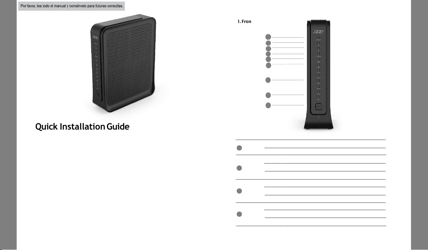
1. FrontPanel
CG2200
Quick
Installation
Guide
ONLINE
Off Internet service isnot available.
Flashing The modem isinitializing.
On Internet service isavailable.
US
Off The initializationis notstarted,or has failed.
Flashing The modemis upstream ranging.
On The modem is upstreamlocked.
DS
Off The initialization is notstarted, or has failed.
Flashing The modemis scanningfor downstreamchannel.
On The modem isdownstream locked.
POWER
Off The modem is poweredoff.
On The modem is poweredon.
1
2
3
4
5
4
3
2
1
6
7
8
9
Page 2
CG3000
Quick
Installation
Guide
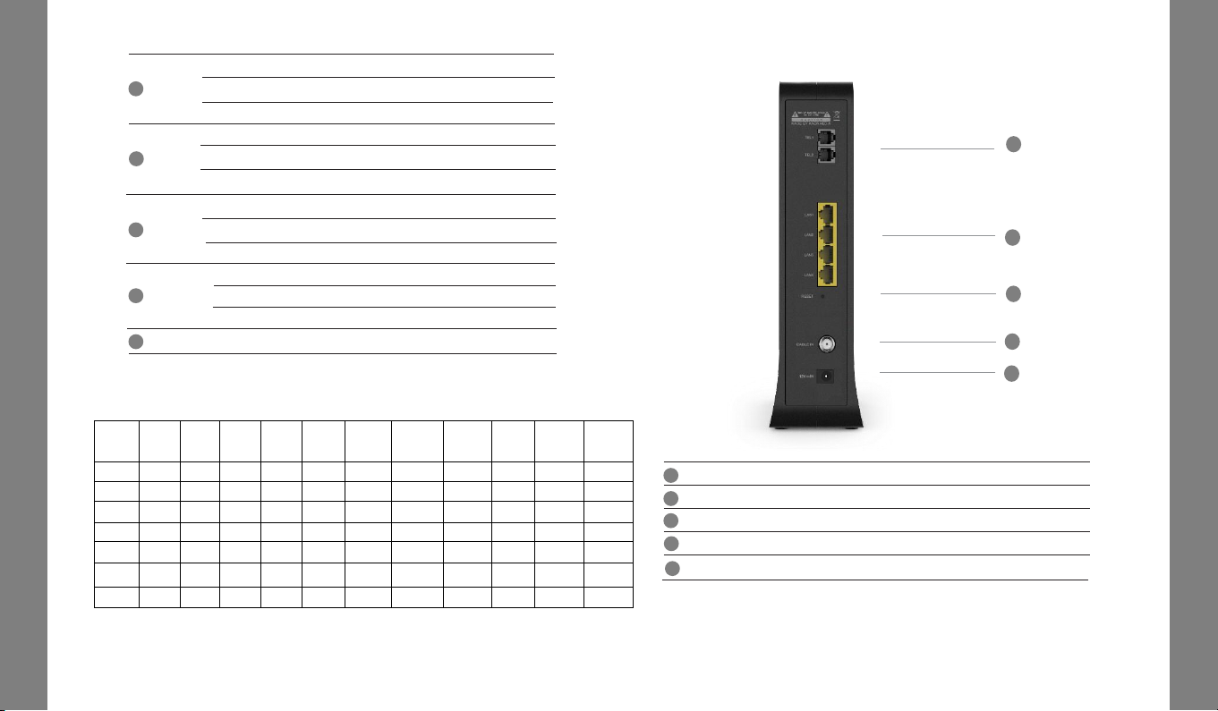
3. RearPanel
CG3000
Quick
Installation
Guide
3
5G
Off
5G WiFiInterface disabled.
On
5G WiFi Interface enabled.
2.4G
5
6
7
8
Off 2.4G WiFi Interface disabled.
Flashing 2.4G WiFi is sendingor receiving data.
On 2.4G WiFi Interface enabled.
Flashing
5G WiFi is sendingor receiving data.
Push
Button for WPS configuration.
WPS
9
3
2
1
4
5
2. LED Status
LED
Power
up
Initial
DS
scan
DS
locking
US
ranging
Request
CM IP
Request
CM
config
CMTS
register
Complete
Request
MTA IP
Request
MTA
config
Restart
Voice
service
Telephone
Register
complete
Power On On On On On On On On On On On
DS
Blinking
Blinking
On On On On On On On On On
US
Blinking
Off Off
Blinking
On On On On On On On
ONLINE
Blinking
Off Off Off Off Blinking On On On On On
2.4G/5G
Off On/Off On/Off On/Off On/Off On/Off On/Off On/Off On/Off On/Off On/Off
ETH1~4 Off On/Off On/Off On/Off On/Off On/Off On/Off On/Off On/Off On/Off On/Off
TEL1~2 Off Off Off Off Off Off Off Blinking Blinking Blinking On
TEL1~2
Off
The telephony service isnot available.
Flashing
The telephony line is in use.
On
The telephony service is available.
ETH 1~4
Off
The LAN portis notconnected.
Flashing
The LAN portis sendingor receiving data.
On The LAN portis connected.
CG2200
Quick
Installation
Guide
CG2200
Quick
Installation
Guide
RESET
Pin-hole for factory reset.
LAN1~4
RJ45 Ethernet ports to connect your PC or home network devices.
CABLE IN Connectsthe coaxialcable forcable internet service.
3
2
1
4
TEL1~2
RJ11 Telephone ports to connect your phone or fax.
5
12VIN
Connects theunitto DC 12V power.
Page 3
CG3000
Quick
Installation
Guide
4. Connecting and Installing devices
Before installation, please check with your serviceprovider to ensure that
the cable broadband is active.
CG3000
Quick
Installation
Guide
Phone
6. Package Content
CG2200
PowerAdaptor
EthernetCable
(CAT5/RJ45)
QuickGuide
Quick Guide
5. Instruction for Connecting Modem – PC
1) Make sure the following:
- YourCable Modem is powered ON. The power LED will be turned ON.
- YourPC is turned-on and connected to Cable Modem using an Ethernet cable.
- Connect tightly the coaxialcable to thecable outlet.
- After Online LED is ON, Cable Modem becomes online.
2) Configure your PC to obtainan IP address from a DHCP server.
3) From your PC, start your web browser application like Chrome, InternetExplorer,
or etc.
4) Type a valid URL suchas “www.kaonmedia.com” and <Enter>.
The web site should be open if connected correctly.
CG2200
Quick
Installation
Guide
CG2200
Quick
Installation
Guide
Adaptador ca/cc
Entrada: 100-240 Vca 50/60 Hz 0.8ª
Salida: 12 Vcc 2.5A
This Device must be
installed at a distance of 1
meter or more away from
the telephone, as this may
cause frequency
interference
Page 4
Specification
Specification
MainChipset
(DOCSIS 3.0 24x8) BCM3384ZU
- 2300 DMIPS Zephyr Process, 1GHz dual-issue
- 1600 DMIPS VIPER Process, 600MHz dual
WLAN BCM4360 (3x3 802.11n)
WLAN BCM4360 (3x3 802.11ac)
Memory
Flash: NOR 32MB
RAM : 256MB DDR3
Wi-Fi
802.11 a/b/g/n/ac MU-MIMO
2.4GHz 3x3 + 5GHz 3x3 Dual Band Concurrent
Internal Antennas
Front
12 xLED
(PWR, DS, US, Online, 2.4G, 5G, ETH1~4, TEL 1~2)
WPS Button
Rear
1x Resetpin-hole
4 x GbE LAN Ports
1 x CableIn
2 x TELPorts
1 x Power In
Power
DC 12V (2.5A)
Package
CG2200
User Guide
Ethernet Cable
PowerSupply
Serial Label, Giftbox Label
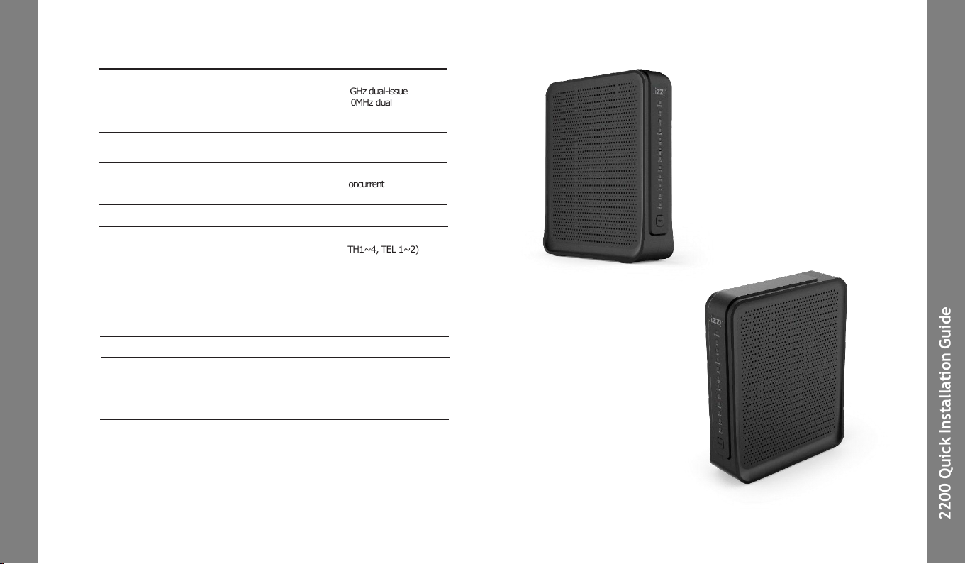
Exterior Design
Exterior Design
CG2200
Quick
Installation
Guide
CG2200
Quick
Installation
Guide
Mesh
KAON Smart Mesh
Page 5

CG3000
Quick
Installation
Guide
CG3000
Quick
Installation
Guide
CG2200
Quick
Installation
Guide
CG2200
Quick
Installation
Guide
NOTE: This equipment has been tested and found to comply with the limits for a
Class B digital device, pursuant to part 15 of the FCC Rules. These limits are
designed to provide reasonable protection against harmful interference in a
residential installation. This equipment generates, uses and can radiate radio
frequency energy and, if not installed and used in accordance with the instructions,
may cause harmful interference to radio communications. However, there is no
guarantee that interference will not occur in a particular installation. If this
equipment does cause harmful interference to radio or television reception, which
can be determined by turning the equipment off and on, the user is encouraged to
try to correct the interference by one or more of the following measures:
—Reorient or relocate the receiving antenna.
—Increase the separation between the equipment and receiver.
—Connect the equipment into an outlet on a circuit different from that to which
the receiver is connected.
—Consult the dealer or an experienced radio/TV technician for help.
This device complies with part 15 of the FCC Rules. Operation is subject to the
following two conditions: (1) This device may not cause harmful interference, and
(2) this device must accept any interference received, including interference that
may cause undesired operation.
Caution : Any changes or modifications in construction of this device
which are not expressly approved by the party responsible for compliance
could void the user's authority to operate the equipment.
The antenna(s) used for this device must be installed to provide a
separation distance of at least 20 cm from all persons and must not be colocated or operating in conjunction with any other antenna or transmitter.
Page 6

1 2
How to access Kaon
Web Page
Network Configu
ration
5 6
How to access Kaon Web Page
Access theweb server, and check the equipment status and progress
usersettings.
1 Type http://192.168.0.1 on your web browser address bar.
2 Enter username and password. (User Name : admin / Password: Find it on label
on the set)
3 Check thestatus of thedevice software information on the STATUS table.
Network Configuration
Enable to set the IP address available on the device, and this IP is
used toaccess theweb server.The IP address must notbe forgotten.
>>LANsetting
1 IPv4 setting issupported.
2 Click “Apply” button on the bottom of thepage after inserting IP address on the
inputentries.
2
2
3
1
1
1
Page 7

3
Network Configu
ration
Network Configuration
If ISP uses DHCP, select “DHCP” for WAN Connection Type.
If ISP uses static IP addressing, select “Static IP” for WAN Connection Type,and enter the information(GW, Subnet Mask, DNS)
provided by ISP.
>>WANsetting
1 WAN connectionType.
SelectDHCP or Static IP to be applied.
If DHCP is selected, IP assigned automatically from DHCPserver can be used
(recommended).
If Static IP is selected,IP generatedby user settingcan be used.
2 WhenStatic IP is selected, enterexactly the IP into theinput textfields.
3 Click “Apply” button on the bottom of the page after inserting all data into the
each inputentry.
1
1
2
3
4
5
2
3
4
DHCP
Server Configu
ration
DHCP Server Configuration
If the DHCP server is activated,the devices connectedto the equip-
ment can getassignedautomatically a private IP address.
1 SelectDHCP on the Network menu.
2 If you select “Yes” radio button, theDHCP Serveris activated.
3 Enter thestarting IP address available in the DHCP Server.
4 Enterthequantity of IP address to be assigned.
5 Enter thelease time.(Defaultrecommended)
6 Click ”Apply” button to setthe information to be applied.
7 8
6
Page 8

9 10
Wireless Configu
ration
(Radio)
Wireless Configu
ration
(Primary
Network)
Wireless Configuration
(Radio)
5 6
Set whether wireless, and the default information. The default settingsrecommended.
1 Select “Radio” on wirelessinterface.
2 If you select “Enabled” on wireless, Wireless isactivated.
3 Set the usable channel bandwidth (Defaultrecommended).
4 Usable to set whether automatic or certain channel. Performancemay be affected
by thedegreeof wireless congestion on a certainchannel.
5 Click ”Apply” button to setthe information to be applied.
1
2
3
4
5
Wireless Configuration (Primary Network)
Youset SSID and authenticationmethodfor connection to WiFi
network.
1 Set SSID on connecting WiFi network.
2 Selectthe applicable encryption method for theaccess authentication.
3 Selectthe applicable typeof AES or TKIP+AES uponthe access authentication.
4 “Show Key” Check-box is checked,theinserted password is available to be read
on the textbox.
5 4 WEP keys aresupported, andat least 1 key is usable.
6 Click ”Apply” button to setthe information to be applied.
1
2
3
4
5
Page 9

11
Status
(Security)
7
Status (Security)
Youset theaccount information to enable to access to the
equipment.
1
5
2
3
4
12
Spec
trum Analyzer (DS/US)
8
Spectrum Analyzer (DS/US)
Spectrum Analyzer enables the technicians to configure
an interactive GUI to understand about characteristics on
the CM, it works normally as they utilize a regular
spectrum analyzer.
1 ● Mai n Control
2 - PRESET button : Resets all the settings back to its default values.
3 - HOLD button : Stops the spectrum analyzer from running.
4 - RUN button : Starts the spectrum analyzer.
5 ● Settings
- FREQUENCY : Specifies the frequency (center, start, or stop) to monitor
in terms of Hz.
- SPAN : Specifies how wide of a span to view in terms of Hz.
- AMPLITUDE : Sets the reference level (offset) of the input signal.
- BW : Bandwidth
- MEASUREMENTS
1 Type http://192.168.100.1:8080 on your web browser address bar.
2 Click ‘RUN” button to run spectrum analyzer.
1 Click “Status” menuon “Status”page.
2 Input userID.
3 Inputnewpassword on New Password text box and input theequal one to
Re-Enter New Password text box.
4 Input the password of current userID to get theuserauthentication.
5 Click ”Apply” button to setthe information to be applied.
Page 10
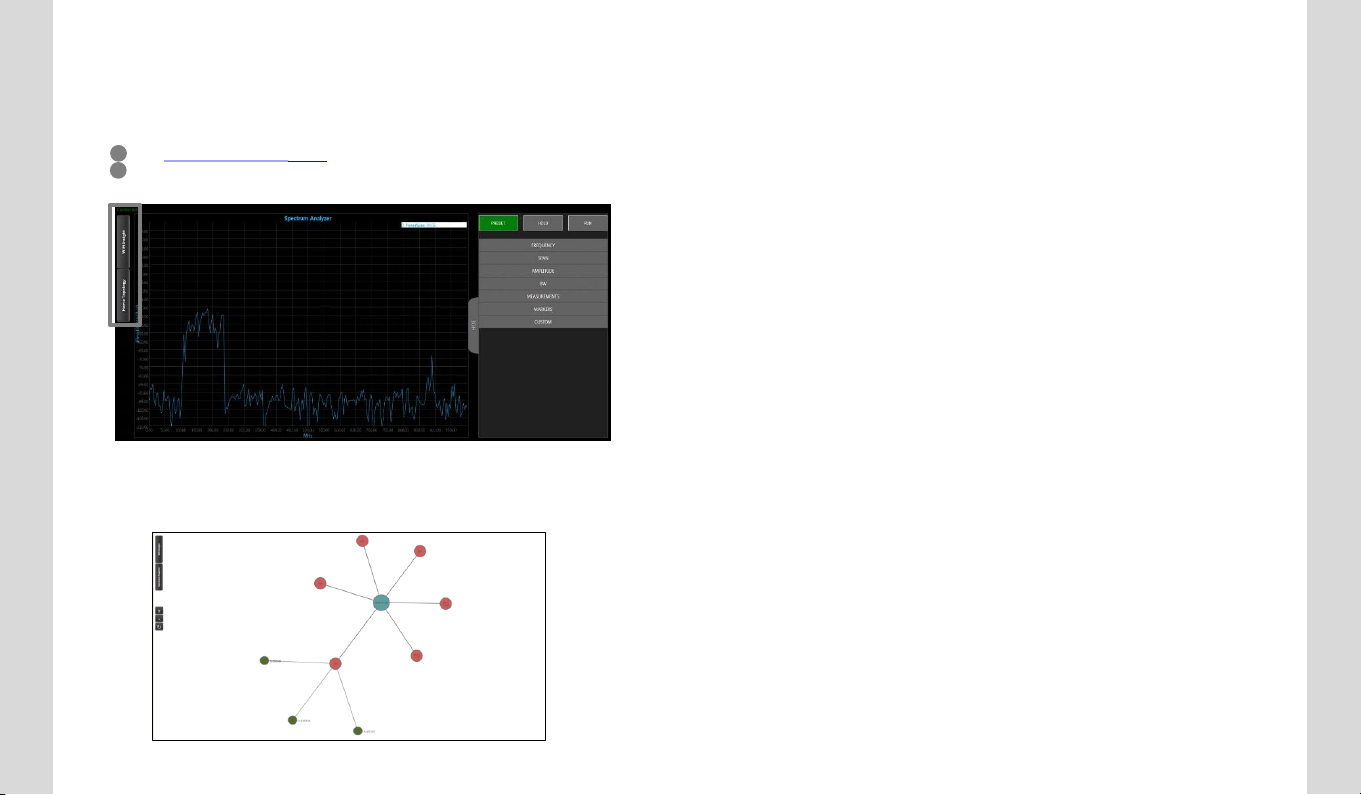
Wireless Insight
9
Wireless Insight
Wireless Insight is able to support that technician can configure an
interactive GUI to do following cases.
In addition, Home Topology tool will help to see the current
network connection via the AP.
14
13
1 Type http://192.168.100.1:8080 on your web browser addressbar.
2 Push the WiFi Insight on left side of web browser
Page 11

109
TROUBLESHOOTING
TROUBLESHOOTING
Use this section to solve common problems with the CG2200 and your network.
Problem: None of the LEDs Turn On
The CG2200 is not receiving power, or there is a fault with the device.
1. Ensure that you are using the correct power adaptor. (You should
use CG2200 Power adapter, don’t’ use other adaptor)
2. Ensure that the power adaptor is connected to the CG2200 and the
wall socket (or other power source) correctly.
3. Ensure that the power source is functioning correctly. Replace any
broken fuses or reset any tripped circuit breakers.
4. Disconnect and re-connect the power adaptor to the power source
and the CG2200.
5. If none of the above steps solve the problem, consult your vendor.
Problem: Some of the LEDs does not Display as Expected
1. Ensure that you understand the LED’s normal behavior
(See LEDs on page 1~2).
2. Ensure that the CG2200’s hardware is connected correctly; see the
Quick Installation Guide.
3. Disconnect and re-connect the power adaptor to the CG2200
4. If none of the above steps solve the problem, consult your vendor.
TROUBLESHOOTING
TROUBLESHOOTING
Problem: I Forgot the CG2200’s IP Address
1. The CG2200’s default LAN IP address is 192.168.0.1.
2. You can locate the CG2200’s GUI by entering the LAN domain suffix
into your browser’s address bar (on a computer connected to the LAN).
Depending on your operating system and your network, you may be able
to find the CG2200’s IP address by looking up your computer’s default
gateway. To do this on (most) Windows machines, click Start > Run,
enter “cmd”, and then enter “ipconfig”. Get the IP address of the
Default Gateway, and enter it in your browser’s address bar.
3. If you still cannot access the CG2200, you need to reset the CG2200.
Press reset button on the rear side of CG2200 for at least 3 seconds.
All user-configured data is lost, and the CG2200 is returned to its
default settings. If you previously backed-up a more recent version your
CG2200’s settings, you can now upload them to the CG2200.
Problem: I Forgot the CG2200’s Admin Username or Password
1. The default username is admin, and the default password is printed on
the label on the set.
2. If the default username and password do not work, you need to reset the
CG2200 back to its factory defaults by pressing reset button for at least
3 seconds. All user-configured data is lost, and the CG2200 is returned
to its default settings. If you previously backed-up a more recent version
your CG2200’s settings, you can now upload them to the CG2200.
Page 12

TROUBLESHOOTING
Problem: I Cannot Access the CG2200 or the Internet
1. Ensure that you are using the correct IP address for the CG2200
2. Check your network’s hardware connections, and that the CG2200’s
LEDs display correctly (see LEDs on page 1~2).
3. Make sure that your computer is on the same subnet as the CG2200.
4. If you are attempting to connect over the wireless network, there
may be a problem with the wireless connection. Connect via a LAN
port instead.
5. f the above steps do not work, you need to reset the CG2200 back to
its factory defaults by pressing reset button for at least 3 seconds.
All user-configured data is lost, and the CG2200 is returned to its
default settings. If you previously backed-up a more recent version
your CG2200’s settings, you can now upload them to the CG2200
6. If the problem persists, contact your vendor
Problem: I Cannot Access the Internet and the DS and
US LEDs Keep Blinking
Your service provider may have disabled your Internet access; check the
Status -> Connection screen’s Connectivity State field.
TROUBLESHOOTING
TROUBLESHOOTING
Problem: I Cannot Connect My Wireless Device
1. Ensure that your wireless client device is functioning properly,
and is configured correctly. See the wireless client’s
documentation if unsure.
2. Ensure that the wireless client is within the CG2200’s radio
coverage area. Bear in mind that physical obstructions (walls,
floors, trees, etc.) and electrical interference (other radio
transmitters, microwave ovens, etc) reduce your CG2200’s
signal quality and coverage area.
3. Ensure that the CG2200 and the wireless client are set to use
the same wireless mode and SSID and security settings
4. Re-enter any security credentials (WEP keys, WPA(2)-PSK
password, or WPS). If you are using WPS’s PBC (push-button
configuration) feature, ensure that you are pressing the button
on the CG2200 and enable the wireless client within two
minutes of one another.
5. CG2200’s settings, you can now upload them to the CG2200
6. If the problem persists, contact your vendor.
 Loading...