

Page 1
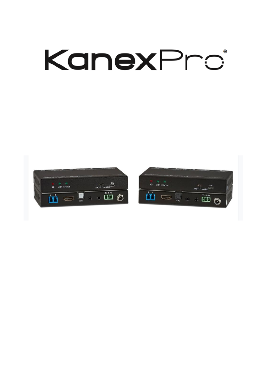
EXT-4KFIBERPRO
HDMI® 2.0 Fiber Optic Extender with 4K/60 up to 300 meters
Extend 4K Video, Audio & Control over Fiber up to 984ft. (300m) with HDR, Dolby
Vision & ARC
All Rights Reserved
Version: EXT-4KFIBERPRO_2019V1.3
Page 2

4K/60 Fiber Optical Extender Set
Preface
Read this user manual carefully before using the product. Pictures are shown in this
manual for reference only. Different models and specifications are subject to real
product.
This manual is only for operation instruction, please contact the local distributor for
maintenance assistance. The functions described in this version were updated till July,
2018. In the constant effort to improve the product, we reserve the right to make
functions or parameters changes without notice or obligation. Please refer to the
dealers for the latest details.
FCC Statement
This equipment generates, uses and can radiate radio frequency energy and, if not
installed and used in accordance with the instructions, may cause harmful interference
to radio communications. It has been tested and found to comply with the limits for a
Class B digital device, pursuant to part 15 of the FCC Rules. These limits are designed
to provide reasonable protection against harmful interference in a commercial
installation.
Operation of this equipment in a residential area is likely to cause interference, in which
case the user at their own expense will be required to take whatever measures may be
necessary to correct the interference.
Any changes or modifications not expressly approved by the manufacture would void
the user’s authority to operate the equipment.
Page 3

4K/60 Fiber Optical Extender Set
SAFETY PRECAUTIONS
To ensure the best performance from this product, please read all instructions carefully
before using the device. Save this manual for future reference.
⚫ Unpack the equipment carefully and save the original box and packing material for
possible future shipment.
⚫ Follow basic safety precautions to reduce the risk of fire, electrical shock and injury
to persons.
⚫ Do not dismantle the housing or modify the module. It may result in electrical shock
or burn.
⚫ Using supplies or parts not meeting the specifications of product may cause
damage, deterioration or malfunction.
⚫ Refer all servicing to qualified service personnel.
⚫ To prevent fire or shock hazard, do not expose the unit to rain, moisture or install
this product near water.
⚫ Do not put any heavy items on the extension cable in case of extrusion.
⚫ Do not remove the housing of the device as opening or removing housing may
expose you to dangerous voltage or other hazards.
⚫ Install the device in a place with fine ventilation to avoid damage caused by
overheat.
⚫ Keep the device away from liquids and hazardous materials.
⚫ Spillage into the housing may result in fire, electrical shock, or equipment damage.
If an object or liquid falls or spills on to the housing, unplug the module immediately.
⚫ Do not twist or pull by force ends of the optical cable. It can cause malfunction.
⚫ Do not use liquid or aerosol cleaners to clean this unit. Always unplug the power to
the device before cleaning.
⚫ Unplug the power cord when left unused for a long period of time.
⚫ Information on disposal for scrapped devices: do not burn or mix with general
household waste, and please treat them as normal electrical wastes.
Page 4

4K/60 Fiber Optical Extender Set
Table of Contents
1. Product Introduction .................................................................................................... 1
2. Features ...................................................................................................................... 1
3. Package List ................................................................................................................ 1
4. Specification ................................................................................................................ 3
5. Panel Description ........................................................................................................ 4
5.1 Transmitter ......................................................................................................... 4
5.2 Receiver ............................................................................................................. 5
6. System Connection ..................................................................................................... 6
7. Panel Drawing ........................................................................................................... 10
8. Troubleshooting & Maintenance ................................................................................ 11
9. Customer Service ...................................................................................................... 12
Page 5

4K/60 Fiber Optical Extender Set
1
1. Product Introduction
The KanexPro EXT- 4KFIBERPRO is an HDMI 2.0 extender set engineered to extend
4Kx2K@60Hz with 4:4:4 Chroma Sampling rate and HDR up to 984ft. (300m) at zero
latency. Compliant with HDCP 2.2, the set includes one transmitter and one receiver
via two- single mode optical fiber ports or two OM3/OM4 multi-mode fiber cables. Front
panel Dip switch allows SPDIF ports on both the sender and receiver to function as
ARC (Audio Return Channel) mode or normal audio support for downstream devices.
This extender can also be controlled over fiber via bi-directional IR and RS-323C.
2. Features
• Send secure, uncompressed and RF/ EMI free video and audio over fiber
• Works with single mode or multi-mode
• Supports HDR, Dolby Vision and 4:4:4 Chroma sampling rate
• Built-in LC connectors on both the transmitter & receiver
• Extends 4K/60 up to 984ft. (300m)
• Extends 1080p/60 up to 1300ft. (400m)
• HDCP 2.2 Compliant
• Supports Audio Return Channel (ARC), EDID & CEC channels
• Bi-directional IR and RS232 pass-though.
• Slim chassis design
• Micro–USB port for on the spot firmware update
• Locking power supply & mounting ears
• Backed by KanexPro 3-year warranty for parts & labor
3. Package List
▪ 1x Transmitter
▪ 1x Receiver
▪ 2x Power Adapter (12V DC 1A)
▪ 1x RS232 Cable (3-pin to DB9)
▪ 1x 3-pin Terminal Block
Page 6

4K/60 Fiber Optical Extender Set
2
▪ 4x Mounting Ears
▪ 16x Mounting Screws
▪ 8x Plastic Cushions
▪ 1x User Manual
Note: Please contact your distributor immediately if any damage or defect in the
components is found.
Page 7

4K/60 Fiber Optical Extender Set
3
4. Specification
Transmitter
Input
1 x HDMI IN
Input Connector
1 x Type-A female HDMI
Output
2 x OPTICAL OUT; 1 x AUDIO OUT
Output Connector
2 x LC connector; 1 x Toslink connector
Control
1 x IR IN; 1 x IR OUT; 1 x RS232
Control Connector
2 x 3.5mm mini jacks; 1 x 3-pin terminal block
Receiver
Input
2 x OPTICAL IN; 1 x AUDIO IN
Input Connector
2 x LC connector; 1 x Toslink connector
Output
1 x HDMI OUT
Output Connector
1 x Type-A female HDMI
Control
1 x IR IN; 1 x IR OUT; 1 x RS232
Control Connector
2 x 3.5mm mini jacks; 1 x 3-pin terminal block
General
Video Resolution
Up to 4Kx2K 60Hz 4:4:4 HDR
Audio Format
PCM, Dolby Digital, DTS, DTS-HD
HDMI Standard
HDMI 2.0
HDCP Version
HDCP 2.2
Transmission Distance
≤300m via single-mode or OM3/OM4 multi-mode fiber
cables.
Operation Temperature
-10℃ ~ +55℃
Storage Temperature
-25℃ ~ +70℃
Relative Humility
10%-90%
Power Supply
Input: AC 100~240V, 50/60Hz; Output: 12V DC 1A.
Power Consumption
9W (max)
Dimension (W*H*D)
5.10” x 0.78”x 3.30”
Net Weight
(0.38 lbs.) 175g
Page 8

4K/60 Fiber Optical Extender Set
4
5. Panel Description
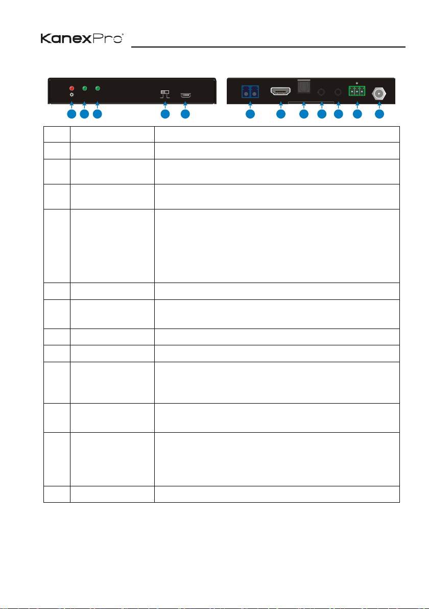
5.1 Transmitter
No.
Name
Description
①
Power LED
Turns red when DC power present.
②
Link status LED
Turns green when the transmitter and receiver link
successful.
③
Work status LED
Turns green when the signal data is transmitted between
transmitter and receiver.
④
Audio Mode
Switch
▪ ARC (Default): Switch the audio mode to ARC.
▪ AUDIO: Switch the audio mode to AUDIO.
The DIP switch must be worked with another switch on
receiver, for more details, please refer to part # 6.
System Application.
⑤
FW
USB port, used for firmware update.
⑥
OPTICAL OUT
Connect to the OPTICAL IN port on receiver via two fiber
cables (A-B; B-A).
⑦
HDMI IN
Connect to HDMI source.
⑧
AUDIO OUT
Connect to audio broadcast device.
⑨
IR IN
Work with far-end IR OUT port on receiver, connect to IR
receiver (with carrier) to collect IR signal to control far-
end display.
⑩
IR OUT
Work with far-end IR IN port on receiver, connect to IR
Emitter to send IR signal to control source device.
⑪
RS232
Makes up bi-directional RS232 pass-through control with
the RS232 port on receiver. If one is connected to control
device (e.g. PC), and the other should be connected to
the third-party that need to be controlled.
⑫
DC 12V
Connect to 12V DC power adaptor.
Tx Rx
ARC
BA
AUDIOARC
LINK STATUS
FW
1
2
3
4
5
6
7
8
9
10 11
12
Page 9
4K/60 Fiber Optical Extender Set
5
5.2 Receiver
No.
Name
Description
①
Power LED
Turns red when DC power present.
②
Link status LED
Turns green when the transmitter and receiver link
successful.
③
Work status LED
Turns green when the signal data is transmitted between
transmitter and receiver.
④
Audio Mode
Switch
▪ ARC (Default): Switch the audio mode to ARC.
▪ AUDIO: Switch the audio mode to AUDIO.
The DIP switch must be worked with another switch on
transmitter, for more details, please refer to part 6.
System Application.
⑤
FW
USB port, used for firmware update.
⑥
OPTICAL IN
Connect to the OPTICAL OUT port on transmitter via two
fiber cables (A-B; B-A).
⑦
HDMI OUT
Connect to HDMI display.
⑧
AUDIO IN
Connect to audio source device.
⑨
IR IN
Work with far-end IR OUT port on transmitter, connect to
IR receiver (with carrier) to collect IR signal to control far-
end source device.
⑩
IR OUT
Work with far-end IR IN port on transmitter, connect to IR
Emitter to send IR signal to control display device.
⑪
RS232
Makes up bi-directional RS232 pass-through control with
the RS232 port on receiver. If one is connected to control
device (e.g. PC), and the other should be connected to
the third-party that need to be controlled.
⑫
DC 12V
Connect to 12V DC power adaptor.
Tx Rx
ARC
B A
AUDIOARC
LINK STATUS
FW
1
2
3
4
5
6
7
8
9
10 11
12
Page 10

4K/60 Fiber Optical Extender Set
6
6. System Application
Usage Precautions:
⚫ Make sure all components and accessories included before installation.
⚫ System should be installed in a clean environment with proper temperature and
humidity.
⚫ All of the power switches, plugs, sockets, and power cords should be insulated and
safe.
⚫ All devices should be connected before power on.
There are four connection ways can be chosen via audio mode switch.
Mode
Switch Status
Description
Transmitter
Receiver
①
ARC
ARC
The audio signal is transmitted from the display
back to HDMI IN and AUDIO OUT ports.
②
ARC
AUDIO
The audio signal is transmitted from the AUDIO
IN to HDMI IN and AUDIO OUT ports.
③
AUDIO
ARC
The audio signal is transmitted from the display
back to the AUDIO OUT port.
④
AUDIO
AUDIO
The audio signal is transmitted from the AUDIO
IN to the AUDIO OUT port.
Note: When the switch status is set as mode 1,2 or 3, the amplifier, display must
support ARC.
Page 11
4K/60 Fiber Optical Extender Set
7
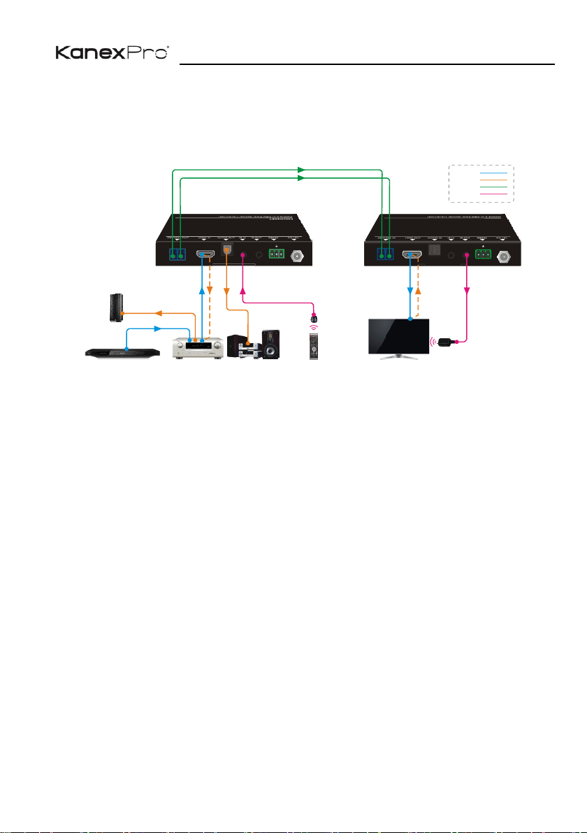
Mode ①: Transmitter: ARC; Receiver: ARC
The audio signal is transmitted from the display back to HDMI IN and AUDIO OUT
ports.
Connection procedure:
Step1. Connect the OPTICAL OUT port of the transmitter to the OPTICAL IN port of
the receiver with two OM3/OM4 multi-mode fiber cables.
Step2. Connect an amplifier to the HDMI IN port of Transmitter, and then connect HDMI
source device (e.g. Blue-ray DVD) and Speaker to the amplifier.
Step3. Connect a broadcast device (e.g. Speaker) to the AUDIO OUT port of
transmitter with Toslink audio cable.
Step4. Connect a display device (e.g. TV) to the HDMI OUT port of receiver with HDMI
cable.
Step5. Bi-directional IR control: Both transmitter and receiver have IR IN and IR OUT
port. When one model use for IR signal receiver, the IR signal must be sent out
by the other model.
For example: When IR IN port of transmitter connects with an IR receiver, the IR
Emitter must be connected to the IR OUT port of receiver.
Step6. Bi-directional RS232 control: Both transmitter and receiver have RS232 port.
When one model use for control device, the other must be used for the third-
party device needed to be controlled.
For example: When RS232 port of transmitter connects with a control PC, the
third-party device must be connected to the RS232 port of receiver.
Tx Rx
ARC
BA
Tx Rx
ARC
B A
Transmitter : ARC
Blu- Ray DVD Spea ker TV Rem ote
TV Rem ote
Receiver: ARC
HDMI :
Opti cal:
Audi o:
Cont rol:
300m
APML IFIER
ARC
ARC
Disp lay
IR Emi tter
ARC
Spea ker
Page 12
4K/60 Fiber Optical Extender Set
8
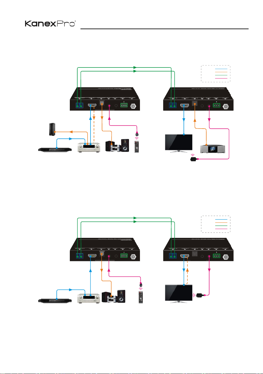
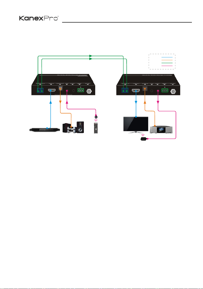
Mode ②: Transmitter: ARC; Receiver: AUDIO
The audio signal is transmitted from the AUDIO IN to HDMI IN and AUDIO OUT ports.
Mode ③: Transmitter: AUDIO; Receiver: ARC
The audio signal is transmitted from the display back to the AUDIO OUT port, but not to
HDMI IN port.
Tx Rx
ARC
BA
Tx Rx
ARC
B A
Transmitter: ARC
TV Rem ote
TV Rem ote
Receiver:AUDIO
HDMI :
Opti cal:
Audi o:
Cont rol:
300m
Blu- Ray DVD
APML IFIER
ARC A RC
ARC
Disp lay
Spea ker
IR Emi tter
Digi tal Radio
Spea ker
Tx Rx
ARC
BA
Tx Rx
ARC
B A
Transmitter: AUDIO
Spea ker TV Remote
TV Remote
Receiver: ARC
HDMI:
Opti cal:
Audi o:
Control:
300m
Disp lay
IR Emi tter
ARC
Blu-Ray DVD
APMLIFIER
Page 13
4K/60 Fiber Optical Extender Set
9
Mode ④:Transmitter: AUDIO; Receiver: AUDIO
The audio signal is transmitted from the AUDIO IN to the AUDIO OUT port.
Tx Rx
ARC
BA
Tx Rx
ARC
B A
Transmitter: AUDIO
Blu-Ray DVD
Speaker TV Remote
TV Remote
Receiver: AUDIO
300m
Display
HDMI:
Optical:
Audio:
Control:
Digital Radio
Page 14
4K/60 Fiber Optical Extender Set
10
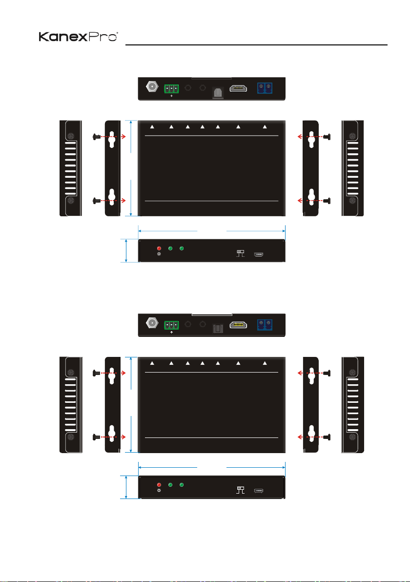
7. Panel Drawing
6-1 Transmitter
6-2 Receiver
Tx
Rx
ARC
B
A
DC 12V
RS232
IR OUT
IR IN
AUDIO O UT
HDMI IN
OPTIC AL OUT
HDMI 2.0 w/ ARC Fiber Optic al Transmitter
AUDIOARC
LINK STATUS
FW
130 mm
84 mm
20 mm
AUDIOARC
LINK STATUS
FW
Tx
Rx
ARC
B
A
DC 12V
RS232
IR OUT
IR IN
AUDIO I N
HDMI OU T
OPTIC AL IN
HDMI 2.0 w/ ARC Fiber Optic al Receiver
130 mm
84 mm
20 mm
Page 15

4K/60 Fiber Optical Extender Set
11
8. Troubleshooting & Maintenance
Problems
Potential Causes
Solutions
Losing color or vague
double image in HDMI
display.
Poor quality of the optical
fiber cable.
Change to qualified OM3
cable.
Power LED is off, No
response for operations
Not been powered.
Power up the unit.
Poor contact.
Make sure power adapter is
in well contact.
No output on the
display.
Source or Display is off.
Turn on the source/ display.
Poor contact.
Check the HDMI ports one
by one to make sure they
are in well contact and not
loosely plugged
The display doesn’t
support the resolution.
Connect the display to the
transmitter and capture its
EDID data before using.
Note: If your problem still persists after following the above troubleshooting steps,
please contact your local dealer or distributor for further assistance. Or call us directly
at (888) 975-1368 or email to [email protected]
Page 16

4K/60 Fiber Optical Extender Set
12
9. Customer Service
The return of a product to our Customer Service implies the full agreement of the terms
and conditions hereinafter. There terms and conditions may be changed without prior
notice.
1) Warranty
The limited warranty period of the product is three years parts and labor from the
date of purchase.
2) Scope
These terms and conditions of customer service apply to the customer service
provided for the products or any other items sold by authorized distributor only.
3) Warranty Exclusions:
⚫ Warranty expiration.
⚫ Factory applied serial number has been altered or removed from the product.
⚫ Damage, deterioration or malfunction caused by:
✓ Normal wear and tear.
✓ Use of supplies or parts not meeting our specifications.
✓ No certificate or invoice as the proof of warranty.
✓ The product model showed on the warranty card does not match with the
model of the product for repairing or had been altered.
✓ Damage caused by force majeure.
✓ Servicing not authorized by distributor.
✓ Any other causes which does not relate to a product defect.
⚫ Shipping fees, installation or labor charges for installation or setup of the
product.
4) Documentation:
Customer Service will accept defective product(s) in the scope of warranty
coverage at the sole condition that the defeat has been clearly defined, and upon
reception of the documents or copy of invoice, indicating the date of purchase, the
type of product, the serial number, and the name of distributor.
Page 17

 Loading...