

KAM KSP100 Instruction Manual
KAM SCRATCH PRO 100
PRO SCRATCH MIXER
INSTRUCTION MANUAL
KAM SCRATCH PRO 100
PRO SCRATCH MIXER
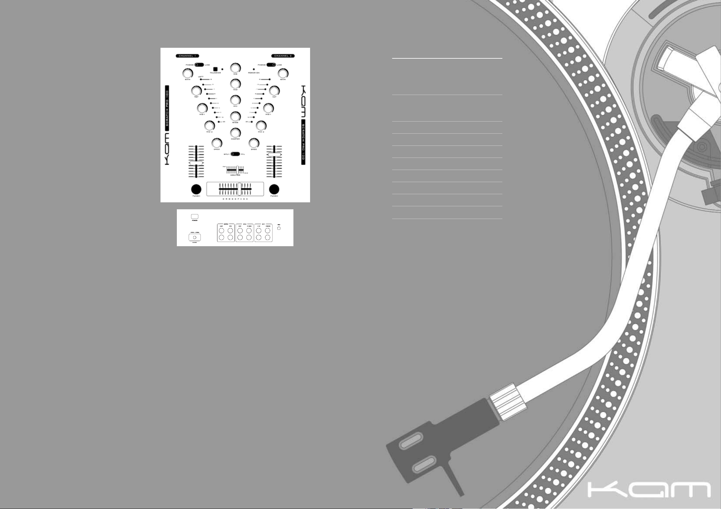
r GAIN CONTROLS
Each music channel has a rotary gain control. The
Gain control adjusts the input level allowing the user
to reduce or increase the sound level to compensate
for quiet recordings. NOTE: care should be taken not
to produce distortion with these controls.
t TONE CONTROLS
Each Phono/line channel has unique four band tone
controls, which can be used to cut and boost specific
frequencies. The bass control alters the level of lower
Bass frequencies, Mid 2 alters lower mid and higher
Bass frequencies, Mid 1 alters higher Mid frequencies
and the Top alters high frequencies. Care should be
taken not to distort the output signal using these
controls.
KAM KILL CUT
The Kill Cut feature allows the user to completely
remove specific frequencies from individual channels.
y CHANNEL LEVEL FADERS
These are used to adjust the output level for each
channel. NOTE: care should be taken not to produce
distortion with these controls.
u PUNCH BUTTONS
These buttons when pressed open the channel and
allow sound to pass to the master output, regardless
of the position of the crossfader. Designed for
transform scratching type effects.
i MICROPHONE CONTROLS
The MC/DJ microphone has its own dedicated level
control and Bass, Mid and Top tone controls. NOTE:
To maximize the performance of this microphone
channel check out the range of Mixer Matched KAM
Microphones.
o TALKOVER (MICROPHONE OVERRIDE)
When depressed the Talkover switch reduces the
music level while the microphone is in use and then
automatically returns the music to normal level when
the microphone is no longer in use. When active the
led indicator glows red.
1) SPLIT / PFL SWITCH
This switch controls the way in which the monitoring
circuit works. In the split position the audio from the
master output is played on one side of the headphones
and the PFL (the track you are mixing in) on the other.
The PFL or channel you are wishing to mix in is
selected by changing the position of the Cue Monitor
Select Fader to the desired channel. (See Cue
Monitor) When the SPLIT/PFL switch is in the PFL
position the individual channel plays back in stereo
through both headphones, selecting which channel is
monitored by the headphone, is made by altering the
cue monitor switch.
1! CUE MONITOR SELECT FADER
This Controls what is monitored in the headphones.
With the cue select fader to the left you should hear
the output from channel 1 in both headphones and
with the cue select fader to the right you should hear
the output from channel 2 in both headphones. With
the cue select fader in the centre you should hear a
mix of both channels 1 and 2.
1@ KAM PROFADE CROSSFADER
This allows the user to mix smoothly between both
music channels. You are able to adjust the curve of
the crossfader with crossfader curve select switch.
1# CROSSFADER CURVE CONTROL (front of mixer)
This controls the output fade characteristics of the
crossfader. With the control turned fully anti-clockwise
the sound will fade out sharply when the crossfader is
moved. With the control fully clockwise the sound
should fade out more slowly when the crossfader is
moved. A sharp fade curve is required for many
scratch techniques.
1$ CUE LEVEL (front of mixer)
This controls the output volume of the headphones.
Care should be taken not to have this set to high as it
could result in damage to both the hearing of the user
and the headphones. The channel to be monitored is
selected via the cue monitor select fader.
1% POWER
The Power On LED will show the current status (lit =
on). Ensure the mixer is turned off when connecting
external equipment.
1^ LED LEVEL DISPLAY'S
The unit has two LED level displays. They show the
Left and Right levels of the Master Output of the
mixer.
1& MASTER OUTPUT CONTROL
This controls the overall output from the mixer, from
the master output to the PA System. NOTE: care
should be taken not to produce distortion with these
controls as this could result in damage to both the
unit and any external equipment connected.
1* VOLTAGE SELECTOR
The KSP100 is dual voltage (110 / 230). Please
ensure the correct voltage is selected for your
country. Failure to set the correct voltage will cause
damage to the unit.
1( REPLACEABLE PROFADE CROSSFADER (not shown)
You are probably already aware that this mixer comes
with a FREE EXTRA KAM ProFADE crossfader.
Crossfaders get more use than any other part of a
mixer so they are always the first thing to wear out.
They are also generally not guaranteed and are a
chargeable item. The Team at KAM think you deserve
more time to enjoy mixing and preparing to be a top
class artist before you need to reach in to your pocket
to pay for a replacement. So with two faders in the
box, compared to other brands you will have twice as
much time to enjoy this product.
© COPYRIGHT LAMBA plc 2003. E&O E.
OVERVIEW
The KAM SCRATCH PRO 100 mixer is designed to
give the DANCE DJ maximum flexibility and features
for minimum cost. This mixer combines all the
features required while maintaining a high level of
build quality and specification.
q INPUTS
The KSP 100 is a 5 input mixer. Both the music
channels have two separate inputs being a
combination of Line and Phono. The unit also features
one dedicated microphone input with separate
Talkover override facility (see Talkover). Care should
be taken when connecting to the mixer that the
correct connections are made. Connecting a CD
player to the Phono input or a turntable to the Line
input can cause damage to the unit. When connecting
a turntable to the Phono input always use the signal
earth cable from the turntable to the ground point on
the mixer. NOTE: always use shielded signal cables to
reduce hum and background noise. The unit should
always be switched off when connecting cables.
w OUTPUTS
The unit has two outputs on the rear 1 x Master
(unbalanced), 1 x Record (unbalanced. These can be
connected to either an external amplifier or tape deck.
Care should be taken not to distort the output signals
(above 0dB on the meters) as this could cause
damage to the external equipment.
e CHANNEL SELECTORS
These are used to switch between Line input and
Phono input on each channel.
1@
wqq
u
1*
r
t
e
y
1)
1!
i
o
1^
1%
SPECIFICATION
INPUT Mic 1mV / 600ohm
Phono 3mV / 50Kohm
Line 150mV / 100Kohm
OUTPUT Amp 1V / 600ohm
Rec 450mV / 600ohm
Headphone 8ohm stereo
FREQUENCY RANGE 20Hz - 20,000Hz
EQ CONTROL 32dB/+10dB
THD 0.03%
S/N RATIO 70dB
AUTO TALKOVER 15dB
POWER SUPPLY External PSU
DIMENSIONS 272 x 254 x 103mm
WEIGHT 2.3kg
Due to continuous product development, specifications are subject to change.
1&
 Loading...