

KAM KPM1750S Instruction Manual
KAMKPM1750
PROFESSIONAL MIXER
OVERVIEW
The Kam KPM1750 mixer is
designed to give the DANCE DJ,
MOBILE DJ, KARAOKE ARTIST,
PUBLIC HOUSE AND SMALL CLUB
INSTALLATION maximum flexibility and
features for minimum cost. This
mixer combines all the features
required while maintaining a high level
of build quality and specification.
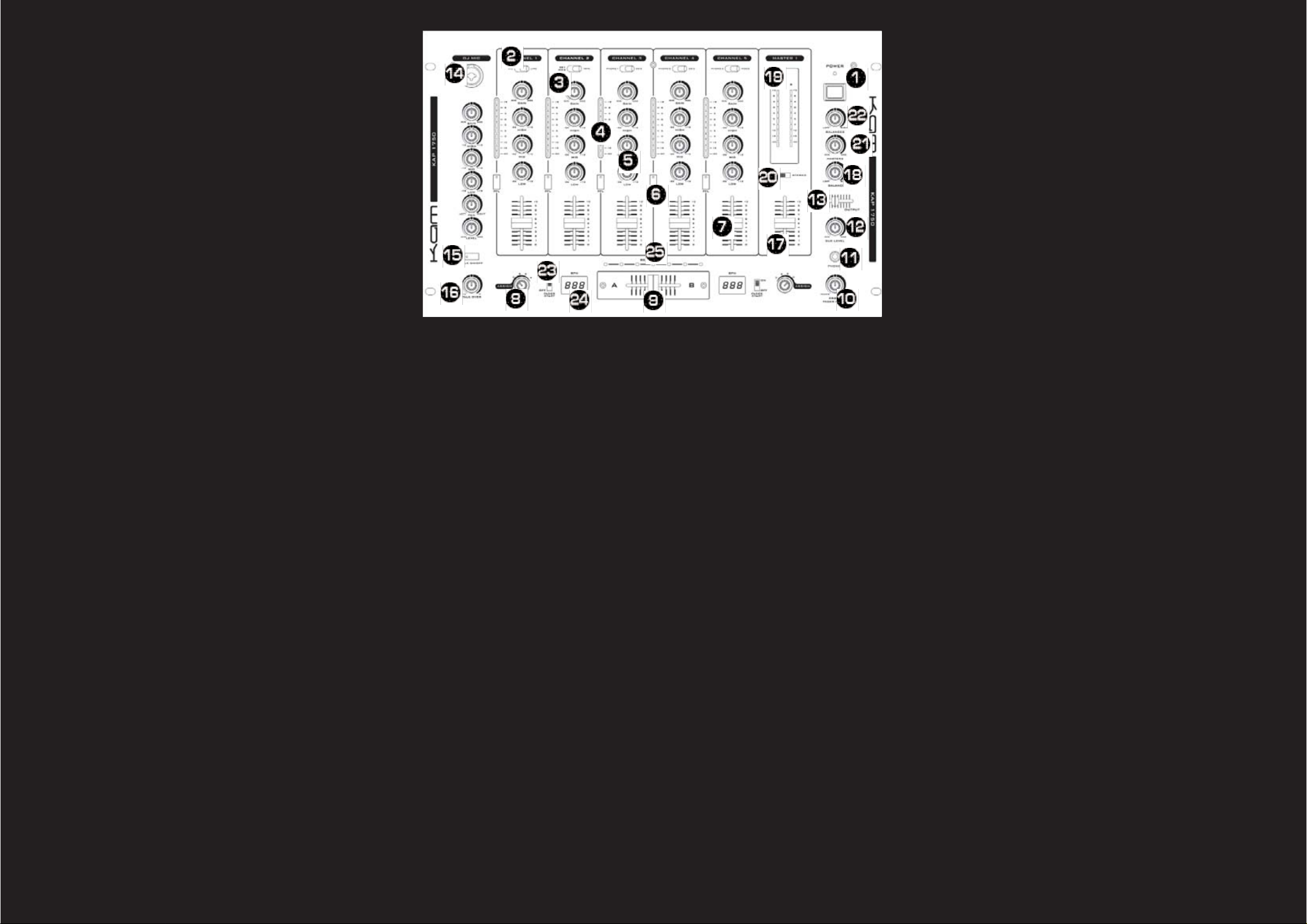
MIXER FEATURE DETAILS
1. MAIN POWER SWITCH - the main power
ON/OFF button. The power LED will glow
red when power is ON.
2. CHANNEL TRANSFORMER SWITCH -
used to select the input source assigned to
each channel. Each channel may only be
assigned one input source at a time.
3. CHANNEL GAIN CONTROLS - adjust the
input level for each channel allowing the
user to reduce or increase the sound level
to compensate for quiet recordings.
4. CHANNEL LEVEL INDICATORS - show a
measurement of the incoming signals for
each channel (before it reaches the individual channel faders).
5. CHANNEL EQUALISER CONTRLS - All of
the channels include a three-band EQ with a
range of +12dB to -26dB. Turning the controls in a counter-clockwise direction will
decrease the appropriate Bass, Mid & High
frequencies within a channel signal. Turning
the knob in a clockwise direction will
increase the appropriate Bass, Mid & High
frequencies within a channel signal.
6. PFL BUTTONS - used to route channels
to the 'Pre Fade Listen' or 'Cue' system. A
red LED inside the PFL button will glow
when a channel is routed to the Cue system. Cue mode sends a channels incoming
signal to the headphones before its level is
set by the CHANNEL FADER (7). The
listening level in your headphones is
adjusted by the CUE LEVEL VOLUME
CONTROL (12). Be sure the CUE MIXING
FADER (13) is turned to the "PFL" position
to hear the selected channel source. More
than one channel can be routed to the Cue
system at the same time.
7. CHANNEL FADER - used to control
individual channel output levels.
8. CROSSFADER ASSIGN SWITCHES - four-
position switches used to assign individual
channels to the CROSSFADER (9). When
either switch is set to the "OFF" position the
CROSSFADER (9) will have no function.
9. CROSSFADER - allows the user to mix
smoothly between the music channels
assigned to either side of it via the
CROSSFADER ASSIGN SWITCHES (8).
When the fader is positioned fully to the left
only the sound from the channel assigned
to the left side will be heard. When the
fader is positioned fully to the right only the
sound from the channel assigned to the
right side will be heard. When the fader is
positioned centrally an even blend of both
channels will be heard.
10. CROSSFADER CURVE CONTROL -
adjusts the shape of the crossfader curve
from a quick cut for scratching or to a
longer fade for mixing.
11. HEADPHONE JACK - connect your
headphones here to monitor the Cue
system.
12. CUE LEVEL VOLUME CONTROL - used
to adjust the headphone volume.
13. CUE MIXING FADER - selects the
source for headphone monitoring. When it
is positioned to the left you will hear only
any music channels you have assigned to
the Cue system using the PFL BUTTONS
(6). When positioned fully to the right you
will hear only the signal from the Master 1
Output. When positioned centrally you will
hear a blend of the two.
14. DJ MICROPHONE CONNECTOR -
accepts 'unbalanced ¼" (6.3mm) jack' or
'balanced XLR' plugs to connect a
microphone to the mixer.
15. TALKOVER BUTTON - When engaged
the talkover function automatically
decreases all signal levels (except the
microphone and the channel 1 level),
whenever the microphone is used. A red
LED inside the Talkover Button will glow
when the talkover function is engaged.
16. TALKOVER CONTROL - used to adjust
the amount by which sound levels are
reduced when talkover is active.
17. MASTER 1 VOLUME CONTROL -
controls the master output level (volume).
To avoid distorted output try to maintain an
average output signal level of 0dB. Be sure
this volume control is always set to zero
before turning the unit on.
18. MASTER 1 BALANCE CONTROL - when
positioned fully anti clockwise both sides of
the Master 1 signal will be routed through
the Left connector of the BALANCED XLR
(27) and the RCA (29) MASTER 1 OUT-
PUTS. When positioned fully clockwise the
signal is routed to the Right connectors.
When placed centrally a stereo mix of both
sides of the Master 1 signal are spread
accross both Left & Right connectors.
19.MASTER 1 LEVEL INDICATOS - show a
measurement of the stereo signal
levels being sent to Master 1 Output.
20. STEREO / MONO SWITCH - in MONO
mode the stereo Master signal is combined
into a mono signal. This single mono signal
is then sent to both the Left & Right
Master 1 Output connectors.
21. MASTER 2 VOLUME CONTROL - used
to control the volume of the signal sent to
MASTER 2 OUTPUT (28). The Master 2
Output can be used for feeding a DJ booth
monitor system.
22. MASTER 2 BALANCE CONTROL - Offers
similar functionality to MASTER 1 BALANCE
CONTROL (18) for the Master 2 Output.
23. FADER START SWITCH - activates the
FADER START feature. When used with a
compatible CD player, you can use the
crossfader to start and stop a CD player
when you move the mixer's CROSSFADER
(9). For example; Assuming you have two
compatible CD players or a compatible dual
CD player connected to channels one and
two. When the Fader Start option is turned
on, sliding the crossfader to the far left
position will trigger playback on CD player 1.
When the crossfader is pushed to the far
right position, playback on CD player 2 will
begin, and CD player 1 will return to the
cue position. Refer to your CD player user
manual for setting CUE POINTS.
24. AUTOMATIC BPM COUNTERS -
automatically calculate the BPM of any
audio source assigned to the respective
sides of the corssfader.
25.BEAT OFFSET INDICATORS - these LED's
help you synchronise the beats of the music
playing on the channels assigned to the
Crossfader.
You will find loads of useful information about cable types, connection
procedures and advice on how to get
the best results from your Kam mixer
at
www.kam.co.uk/tuition.
Instruction Manual
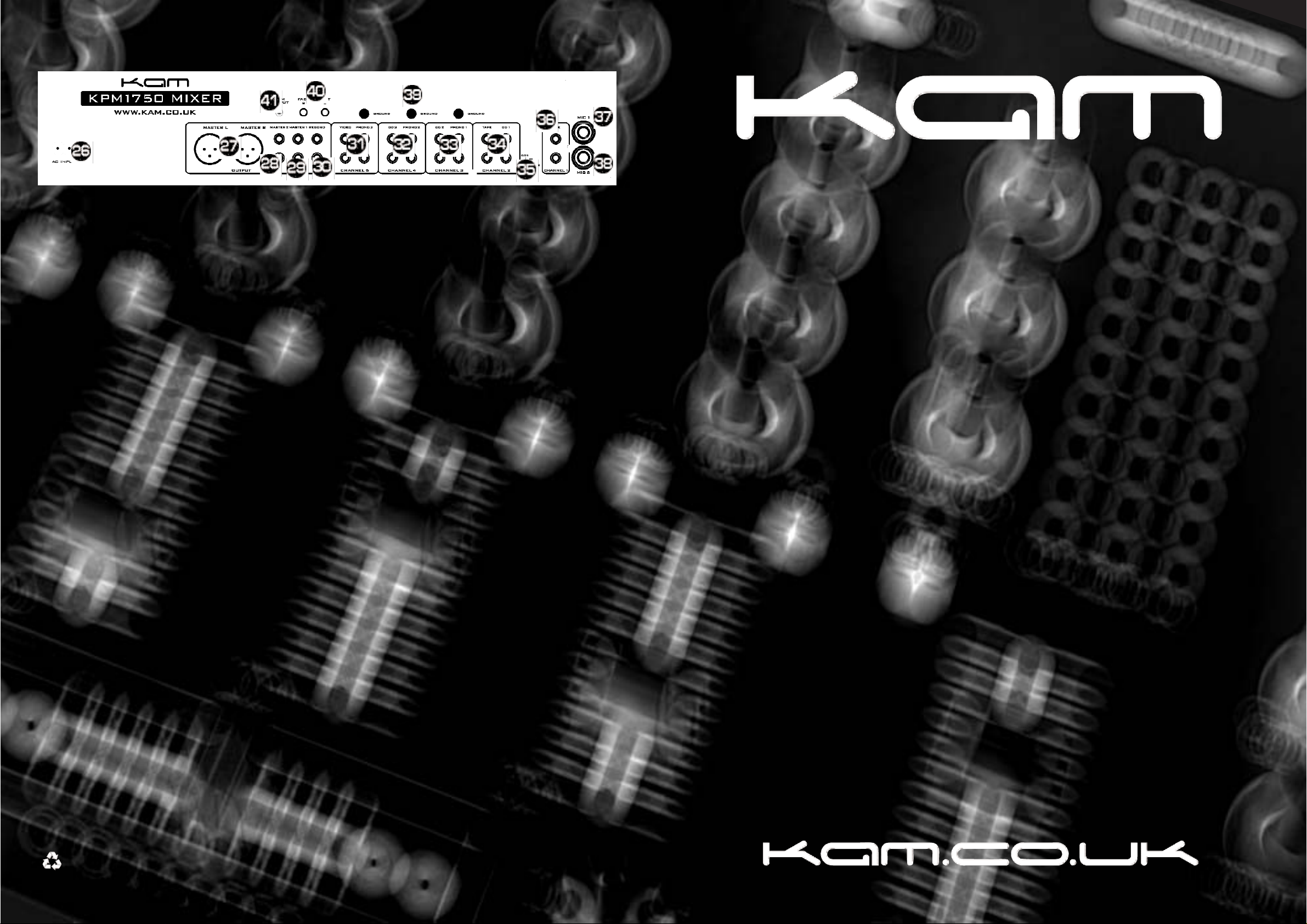
KAP1750
26. AC CONNECTION
27. XLR BALANCED MASTER 1 OUTPUTS - Left & Right Balanced XLR
28. RCA MASTER 2 OUTPUTS - Left & Right line level Unbalanced RCA
29. RCA MASTER 1 OUTPUTS - Left & Right line level Unbalanced RCA
30. REC OUT - line level Unbalanced RCA connectors. The Record Out (REC OUT) level is
dictated by the CHANNEL FADER LEVEL (7), not the MASTER VOLUME CONTROL (12).
PHONO inputs are designed for use only with turntables which produce a low voltage
'phono' level signal. CD, Video & Tape inputs are designed for use only with devices
which produce a ‘line level’ signal.
31. CHANNEL 5: PHONO 3 INPUT/VIDEO JACKS
32. CHANNEL 4: PHONO 2 INPUT/CD 3 JACKS
33. CHANNEL 3: PHONO 1 INPUT/CD 2 JACKS
34. CHANNEL 2: CD 1 /TAPE INPUT JACKS
35. CD 1/MIC 2 SELECTOR SWITCH - This switch is used to determine whether Channel 2
features two line level inputs or one line level and one mic level input. When set to 'mic' the
channel 2 CHANNEL TRANSFORMER SWITCH (25) selects the MIC 2 INPUT JACK (39)
instead of CD 1 INPUT JACKS (35) when in the CD1/Mic 2 position.
36. CHANNEL 1: LINE RCA INPUT JACKS
37. CHANNEL 1: MIC 1 INPUT JACK - use a ¼" (6.3mm) jack plug to connect a
microphone to the Mic input for channel 1 .
38. CHANNEL 2: MIC 2 INPUT JACK - use a ¼" (6.3mm) jack plug to connect a
microphone to the Mic input for channel 2 .
39. GND (GROUND TERMINAL) - Connect each of your turntable ground leads to either
of the three ground terminals.
40. FADER START OUTPUT JACKS - used to connect the mixer to an appropriately
equipped CD player.
41. TRIM OUTPUT CONTROL - used to adjust the Master 1 Output signal to a level that is
appropriate for your PA system. Its purpose is to prevent over enthusiastic DJs from sending excessive signal levels from the mixer that may damage your PA.
REAR PANEL CONNECTIONS
SPECIFICATIONS
INPUT Mic 1mV / 600 Ohm : Phono 3mV / 47 Kohm : Line 200mV / 47 Kohm
OUTPUT Amp 1V /1k Ohm : Rec 400mV / 1k Ohm
Headphone >8 Ohm stereo
FREQUENCY RANGE 20Hz~20KHz
Channel EQ -26dB /+12dB : Mic EQ +/-12dB
THD 0.05% -:- S/N RATIO 78dB
POWER SUPPLY Internal
DIMENSIONS 272 x 254 x 103mm -:- WEIGHT 6.3 Kgs
Due to continuous product development, specifications are subject to change.
when this product is no longer functional take to a recycling plant for envirnmentally friendly disposal
 Loading...