


KMD10
product manual
www.kam.co.uk
KMD10
product manual
Overview
Thank you for purchasing your new Kam KMD10 Mixing Console.
The KMD10 is designed to serve a wide range of uses for Live Sound,
Install or Project Studio. Like all Kam products it is designed to offer
professional features and high quality manufacturing that deliver
outstanding value for money.
Key Features
2 x 375W RMS @ 4 Ohms
10 channels/20 inputs : 6 x mic/line & 14 line
Built in 20BIT DSP Effects System
7 Band Master Graphic EQ
Electronically balanced inputs
Inserts on Mic Channels, Master & Alt 3&4
3 band swept & 4 band channel EQ
2 x Aux Send & Return System (pre/post)
Full Mute/Alt 3&4 sub mix system
Fully routable Control Room system
Professional PFL/Solo system
Independent Amp inputs & PSU
Positioning
When using the built in amplification it is important not to block the
air intake vents on the rear panel. These are essential for the dual
speed fans to keep the unit cool during operation.
Avoid exposing the unit to rain or excessive levels of humidity during
operation.
[5]. Line Input (Mic Channels 1 to 6 only). Use this 1/4” jack sockets to
attach any line level audio source (keyboard, CD player etc).
This socket is electronically balanced so accepts either a balanced
or unbalanced audio signal and automatically self adjusts
accordingly.
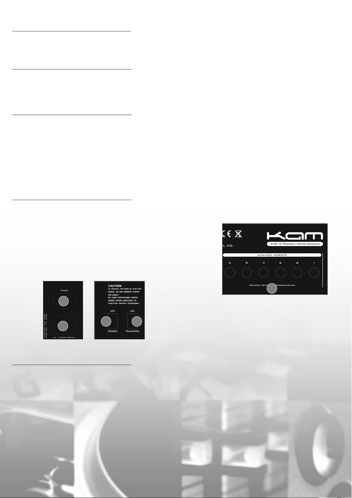
[6] Channel Insert connections (Channels 1 to 6 only) the microphone channels feature an 'Insert' system. These are
commonly used to connect automatic gain control devices such as
Compressors and noise Gates (like the Kam KCG100 combined
Compressor/Gate). The Insert system follows industry standard
protocol. To use it you will need a specially configured 'Y Insert
Cable'. These cables have a single TRS 1/4” jack connector at one
end and a pair of standard mono TS 1/4” jack connectors at the
other. To use the system you connect the single TRS connector to the
appropriate 'Channel Insert' connection found on the rear panel of
the unit. Although the TRS connector used here is physically the
same as that used for a stereo audio connection (commonly used
for headphones) in this context it is wired very differently internally.
TRS actually stands for 'Tip', Ring', 'Sleeve'; which in turn refers to the
fact that the shaft of the connector is split into three isolated
sections. The Tip section is wired to one of the two mono connectors
of your 'Y Insert Cable' and this is used as a signal Send (which you
connect to the input of your processor). The middle or 'Ring' section
is wired to the other mono connector and this is used as a signal
Return (which you connect to the output of your processor).
The 'sleeve' section is used as a ground connection.
[1] IEC main power inlet connector - use this standard IEC connector
to connect the KMD10 to the mains. This inlet supplies mains power
to both the Mixer and Amplifier Sections of the unit.
[2] Mixer Main Power switch - use this switch to turn on & off the
mains power supply to the Mixer section ONLY of the KMD10.
The Amplifier section has its own dedicated power switch
[54].
54
1
Rear Panel
The 'Channel Strips'
[3]. XLR Input (Mic Channels 1 to 6 only). Use this mic level XLR input
to connect your micr
microphones with the KMD10. You cannot use this XLR connection
for line level audio signals.
[4] Phantom Power switch - the KMD10 Mic inputs feature a 48V
Phantom Power system to facilitate use of Condenser Micr
that require an external power source. To use; move the switch
marked 'Phantom' (found on the rear panel) to the on position and
Phantom Power will be deliver
e should be no adverse ef
Ther
Condenser mic's and standard dynamic mic's simultaneously… the
dynamic mic's should not be effected by the Phantom Power
supply. When the Phantom Power system is active you should see
the +48V red status LED
illuminated.
ophone. Y
[60] in the Main Level Meter LED area
ou can use dynamic or condenser
ed to all six XLR mic' input connectors.
fects using a mixtur
2
4
ophones
e of powered
Rear
Panel
6
[7]. L (mono) & R line inputs (Line Channels 7 to 10 only) - use these
unbalanced 1/4” jack sockets to connect any line level audio
source. Use the L input when you wish to attach a mono source (EQ
a vintage synthesiser) as this socket is automatically split and sent to
both L&R channels of the main mix when ther
the R input. Use both connections when connecting a stereo source
(EG a CD player).
[8]. Lo Cut switch (Mic Channels 1 to 6 only). This button applies an
18dB per octave High Pass filter that completely r
frequencies below 75Hz. We highly recommend using this filter for
hand held vocal microphones because it eliminates handling noise.
It is also worthwhile using it for any microphone or instrument that is
not intended to pr
of low frequency feedback and can deliver an overall mix with
greater clarity.
[9]. Gain - Use this contr
level meters to adjust the input signal level so that it peaks at ar
the 0dB mark on the level meter. You will notice two different sets of
calibration ar
applies a different amount of gain to the microphone and line
inputs.
The +4 marking corr
standardised professional line level of +4dBu. The -10 marking
corresponds to the 'unity' position for a standard domestic line
level -10dBu signal. These two markings ar
to position the gain control so that the gain circuit is neither
increasing nor decreasing the signal level for each different line level
signal type.
oduce bass because it also r
ol in conjunction with the PFL system & the
ound the contr
esponds to the 'unity' setting for a signal at the
ol. This is because the gain cir
e is no connection to
emoves all
educes the chances
ound
cuit
e there to show you where
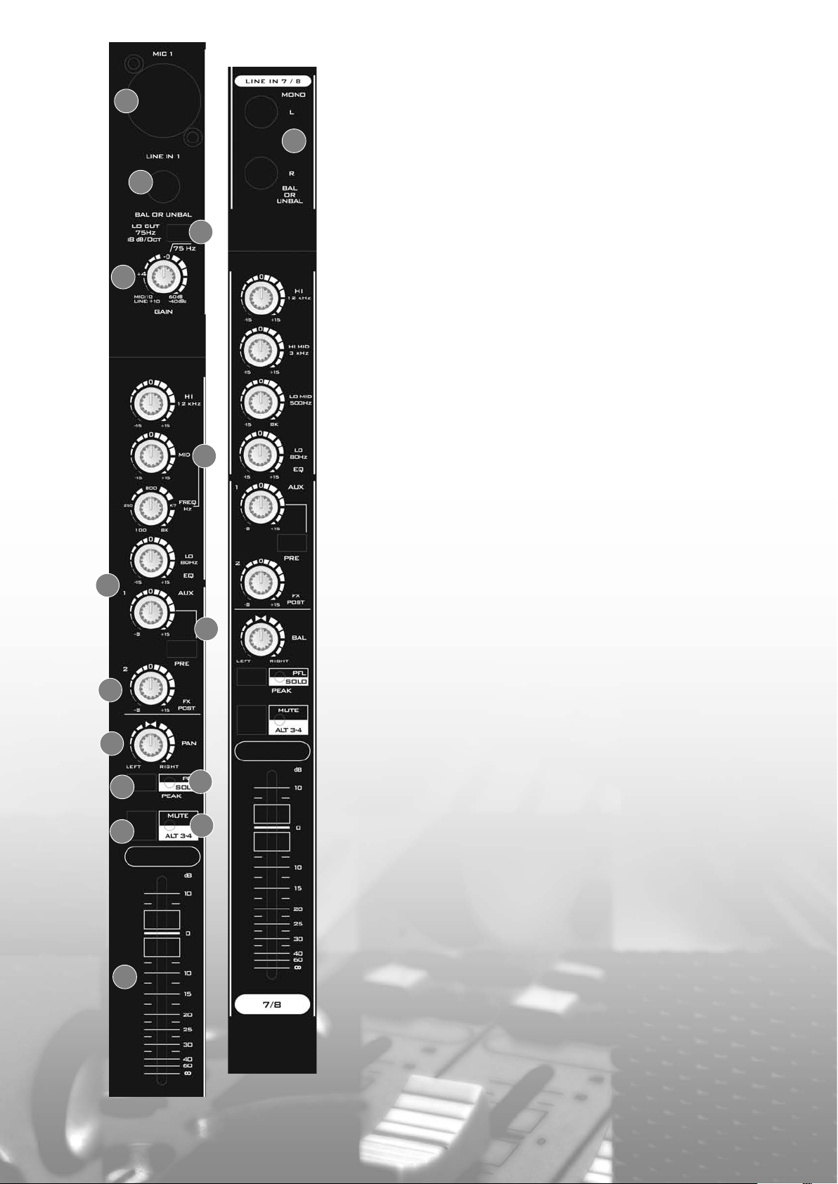
[10] EQ. The mic channels (1-6) and line channels (7-10) feature
different types of EQ system.
The Mic Channels - feature 3 band EQ with a swept mid control. The
Hi control applies +/-15dB of cut and boost to all frequencies above
3
7
5
8
9
12kHz. The Lo control applies +/-15dB of cut or boost to all
frequencies below 80Hz. The mid section has two controls; the upper
control sets whether you cut or boost by +/-15dB. The lower control
lets you choose which mid range frequency you cut/boost. As with
all mid range EQ systems you are effectively adjusting a 'notch' or
'band' of frequencies above and below the selected 'centre'
frequency.
The Line Channels - feature 4 band EQ. The Hi control applies +/12dB of cut and boost to all frequencies above 12kHz. The Hi Mid
control applies +/-15dB of cut or boost to a 'band' of frequencies
above and below 3kHz. The Lo Mid control applies +/-15dB of cut or
boost to a 'band' of frequencies above and below 500Hz.
The Lo control applies +/-12dB of cut or boost to all frequencies
below 80Hz.
[11] Aux 1 'Aux' - use this control to set the amount of signal sent to
the line level audio output marked 'Aux Send' in the master
connections section. How to set up the Aux Send & Return system is
explained below under Master Connections.
11
13
14
15
17
10
16
18
12
[12] Pre button - this button r
button is 'down' the signal from this channel is sent to the Aux output
connection before it reaches the channel level fader - so adjusting
the channel level fader has no impact on the Aux Send level. When
the button is in the 'up' position the signal from the channel is routed
to the Aux Send connection after it has passed through the channel
level fader - so when the button is 'up' turning down the level fader
also turns down the signal sent to the Aux Send. This is useful when
using the Aux Send system to set up an on stage monitor mix as it
enables creation of a separate mix with levels that differ from those
of the main mix.
[13] Aux 2 'FX' - use this control to adjust the signal level sent to the
on board effects processor. To aid versatility the KMD10 also provides
a line level output marked 'EFX Send' in the master connections
section. This output can be used to connect an external effects
processor instead of the on board processor. The 'EFX Send' is wired
'Post Fade' so adjusting the channel level fader also adjusts the EFX
Send level (to both the on board Effects Processor and the external
EFX Send connection).
[14] Pan - when this control is in the central position equal
proportions of the channel signal is sent to the Left and Right
channels of the main mix. Turn the control left and more signal will
be sent to the Left channel of the main mix. Turn the control to the
right and more signal will be sent to the Right channel of the main
mix.
[15] PFL/Solo - this button sends the channel audio signal to the
PFL/Solo system (described in the PFL/Solo section of this manual).
The signal is sent 'Pre Fade' and pre EQ so the measured signal is not
changed by the position of the channel level fader or the EQ
controls… but the signal IS taken immediately after the
channel Gain contr
essentially measuring the input signal level after you have adjusted it
with the input Gain control.
ol (and thus the Insert Sockets), so you ar
elates to the Aux control. When the
e
19
Mic
Channel
Line
Channel
[16] Peak LED - this LED illuminates when the channel signal level is
approaching a level at which it may distort. It is there to act as a
warning to you that you may need to reduce the particular
channels level fader to avoid distortion.
ms two tasks at once when
[17] Mute/Alt 3&4 - this button per
pressed.
1. It mutes (silences) the channel from the main mix.
outes the signal to the Alt 3&4 System
2. It r
(as described in the 'Alt 3&4' section of this manual).
[18] Alt 3&4 LED - when the Alt 3&4 button is engaged this amber
LED illuminates to remind you that you have routed this particular
channel into the Alt 3&4 system.
[19] Channel Fader - use this 60mm fader to adjust the relative level
of the channel in the main mix.
for
 Loading...