

KAM KCM450 Instruction Manual
KAM KCM450
21
20
25
26
30
30
31
32
22
24
23
28
29
29
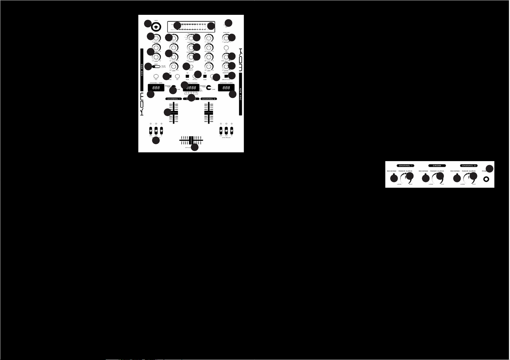
CREATIVE MIXER
OVERVIEW
The Kam KCM450 mixer is designed
to give the DANCE DJ maximum
flexibility and features for minimum
cost. This mixer combines all the
features required while maintaining a
high level of build quality and
specification.
MIXER FEATURE DETAILS
1. MAIN POWER LED - power LED will glow
red when power is ON.
2. CHANNEL TRANSFORM SWITCHES -
select the input source for each channel.
Each channel may only be assigned one
input source at a time.
3. CHANNEL GAIN CONTROLS - adjust the
input level for each channel.
4. LEVEL INDICATORS - show a measure-
ment of whichever signal is selected via the
LEVEL INDICATOR SWITCH (5).
5. LEVEL INDICATOR SWITCH - when set to
Master the Level Indicators show a measurement of the stereo Master signal. When
set to Cue/Pgm the Left Level Indicator
shows a measurement of any channels
routed to the Cue System. When set to
Cue/Pgm the Right Level Indicator shows a
measurement of a combined mono Master
Output signal.
6. CHANNEL EQUALISER CONTRLS - a
three-band EQ with a range of +10dB to 40dB. Turning the controls in a counterclockwise direction will decrease the appropriate Bass, Mid & High frequencies within
a channel signal. Turning the knob in a
clockwise direction will increase the appropriate Bass, Mid & High frequencies within
a channel signal.
7. CUE BUTTONS - used to route channels
to the 'Cue' system. A red LED beside the
PFL button will glow when a channel is routed to the Cue system. Cue mode sends a
channels incoming signal to the headphones
before its level is set by the CHANNEL
13
14
15
4
3
6
16
7
18 18
2
1
5
27
11
12
10
19
8
17
9
FADER (8). The listening level in your headphones is adjusted by the CUE LEVEL VOLUME CONTROL (12). Be sure the CUE MIXING CONTROL (11) is turned to the "CUE"
position to hear the selected channel
source. More than one channel can be
routed to the Cue system at the same time.
8. CHANNEL FADER - used to control
individual channel output levels.
9. CROSSFADER - allows the user to mix
smoothly between channels 1 & 2. When
the fader is positioned fully to the left only
the sound from channel 1 will be heard.
When the fader is positioned fully to the
right only the sound from channel 2 will be
heard. When the fader is positioned
centrally an even blend of both channels will
be heard.
10. SPLIT/PFL BUTTON - controls the way
the monitoring circuit works. In the PFL (up)
position any channel whose ‘Cue’ button is
depressed plays back in stereo through
both headphones. In the SPLIT (down)
position what you hear in the headphones is
determined by the CUE MIXING CONTROL.
11. CUE MIXING CONTROL - selects the
source for headphone monitoring. When
positioned to the left you will hear only channels you have assigned to the Cue system
using the CUE BUTTONS (7). When positioned fully to the right you will hear the
Master Output. When positioned centrally
you will hear a blend of the two.
12. CUE LEVEL VOLUME CONTROL - used
to adjust the headphone volume.
13. DJ MICROPHONE CONNECTOR -
accepts 'unbalanced ¼" (6.3mm) jack' or
'balanced XLR' plugs.
14. MIC GAIN CONTROL - used to adjust
the microphone volume.
15. MIC EQUALISER CONTRLS -the mic
channel includes a two-band EQ with a
range of +12dB to -12dB.
16. TALKOVER BUTTON - When engaged
the talkover function automatically
decreases all signal levels (except the
microphone), by -14dB whenever the
microphone is used. A red LED beside the
Talkover Button will glow when the talkover
function is engaged.
17. KILL SWITCHES - Each side of the
crossfader has a set of 3 frequency band,
3 position, kill switches which completely
remove specific frequencies. Switch positions are; Off, On (the switch says in position and kills the frequency) and Flash (a
sprung action which kills the frequency but
when released returns to the Off position).
18. AUTOMATIC BPM COUNTERS -
automatically calculate the BPM of any
audio source assigned to the respective
sides of the corssfader.
19. EFFECT SEND BUTTONS - route the
individual channels to the Effects System.
20. FX ON BUTTON - swtiches the Effects
System on and off.
21. EFFECT TYPE SELECTOR - choose any
one of 8 different Effect types.
22. EFFECT DEPTH - sets the wet/dry mix.
When positined fully anti-clockwise the
Effects System is bypassed and will cause
no change to your music. When positioned
fully clockwise the Effects System is at full
volume.
23. EFFECT PARAMETER - the function of
this control varies according to the setting
of the EFFECT TYPE SELECTOR (21). Each
Effect Type has a different editable
parameter assigned to this control for
creative real time manipulation.
24. EFFECT BEAT - repeatedly press this
button to select the timing resolution of the
effects. The KCM450 Effects are
automatically synchronised to the tempo of
your music but this button lets you adjust
the timing. The selected timing is shown by
the ‘BEAT’ LEDs (25)
25. BEAT LEDs - show the timing of differ-
ent Effect events; 1/2 means Effect events
will happen every half beat, 3/4 every 3/4
of a beat, 1/1 on every beat, 2/1 every
alternate beat, 4/1 once every four beats.
26. EFFECT DISPLAY - shows the tempo of
audio passing through the Effects System.
27. MASTER OUTPUT VOLUME CONTROL -
controls the master output level (volume).
To avoid distorted output try to maintain an
average output signal level of 0dB. Be sure
this volume control is always set to zero
before turning the unit on.
FRONT PANEL CONTROLS
28. HEADPHONE JACK - used to connect
your headphones to the mixer.
29. CHANNEL FADER CURVE CONTROL -
adjusts the curve of the channel faders
between quick, normal, or long fade.
30 . CHANNEL FADER REVERSE BUTTONS -
reverse the operation of the channel
faders.
31. CROSSFADER CURVE CONTROL -
Adjusts the shape of the crossfader curve
from a quick cut for scratching or to a
longer fade for mixing.
32. CROSSFADER REVERSE - swaps the
channels assigned to either side of the
Crossfader.
You will find loads of useful
information about cable types,
connection procedures and advice
on how to get the best results from
your Kam mixer at
www.kam.co.uk/tuition.
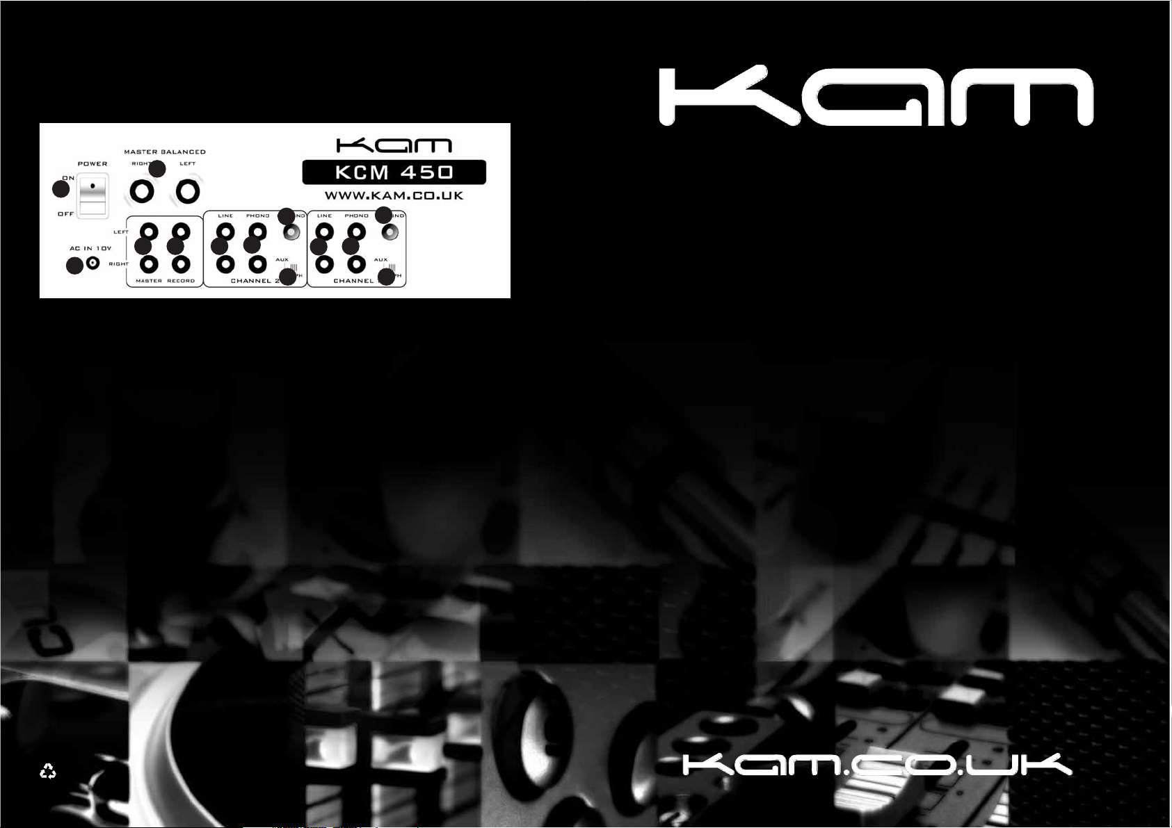
REAR PANEL CONNECTIONS
333435
36
37
39
40
40
41
41
39
38
38
33. MAIN POWER SWITCH
34. AC CONNECTION
35. BALANCED MASTER OUTPUTS - Left & Right line level TRS balanced ¼" (6.3mm) jack
36. MASTER OUTPUTS - Left & Right line level Unbalanced RCA
37. REC OUT - Left & Right line level Unbalanced RCA connectors. The Record Out level is
dictated by the CHANNEL FADER LEVEL (8), it is not influenced by the MASTER VOLUME
CONTROL (27).
38. DEDICATED LINE INPUTS - Channels 1 & 2 each feature a dedicated, stereo,
unbalanced RCA audio input suitable for use only with devices like CD, Video & Tape
players which produce a ‘line level’ signal.
39. SWITCHABLE PHONO/LINE INPUTS - Channels 1 & 2 each feature a stereo RCA input
which can be switched between ‘line level’ and ‘phono level’ operation via the INPUT SELECTION SWITCHES (40). PHONO inputs are designed for use only with turntables which
produce a low voltage 'phono' level signal.
40. INPUT SELECTION SWITCHES - used to set signal input type for channels 1 & 2.
41. GROUND TERMINALS - Connect each of your turntable ground leads to either
of the three ground terminals.
KCM450
SPECIFICATIONS
INPUT; Mic 2mV / 2.2K Ohm : Phono 2mV / 47 Kohm : Line 200mV / 20 Kohm
OUTPUT; TRS JACK 1.23V /600 Ohm : Rec 316mV / 1k Ohm
Headphone >8 Ohm stereo
FREQUENCY RANGE 25Hz~20KHz
Channel EQ -40dB /+10dB
THD 0.02% -:- S/N RATIO 82dB
POWER SUPPLY Internal
DIMENSIONS 355 x 254 x 87mm -:- WEIGHT 5 Kgs
Due to continuous product development, specifications are subject to change.
when this product is no longer functional take it to a recycling plant for envirnmentally friendly disposal
Instruction Manual
 Loading...