

Page 1
jWIN
5.5” BLACK & WHITE SECURITY MONITOR
WITH CAMERA
Page 2

TABLE OF CONTENTS
Introduction ................................................................................................. 3
Caution ........................................................................................................ 3
Out of the Box.............................................................................................. 4
Front View ................................................................................................... 5
Rear View .................................................................................................... 6
Camera View ................................................................................................ 6
Putting it all together .................................................................................... 7
Basic Operations........................................................................................... 8
Set Up for Alternative Audio/Video Connections............................................. 10
Set Up for VCR Connection .......................................................................... 12
Technical Data/Specifications....................................................................... 13
-2-
Page 3

INTRODUCTION
Congratulations on your purchase of the JV-TV2040 and thank you for choosing
j
WIN. The jWIN monitor with camera has a variety of features that make it an
exceptional quality security system for stores, banks, hotels, schools, factories,
apartments, with many applications. In addition to the basic operations, it
provides a variety of special features designed to increase the effectiveness and
ease of providing security.
This manual gives you easy-to-follow instructions for installing and using the JVTV2040. The Table of Contents will show you where to find instructions for using
each feature. While you may not need to read every section in detail at first, we
recommend you at least look them over briefly and that you save this manual for
future reference.
CAUTION
To extend the life of your new equipment and to assure the finest performance,
please adhere to the following cautions.
· Be sure to disconnect the power supply to the television or monitor
when connecting the camera.
· Do not expose the components of this kit to extreme heat, ultraviolet
light, or moisture.
· Protect the contents from rain and direct sunlight.
· Periodically check the cables to be sure they are properly and securely
connected.
· Employ only authorized technicians to service this unit.
-3-
Page 4
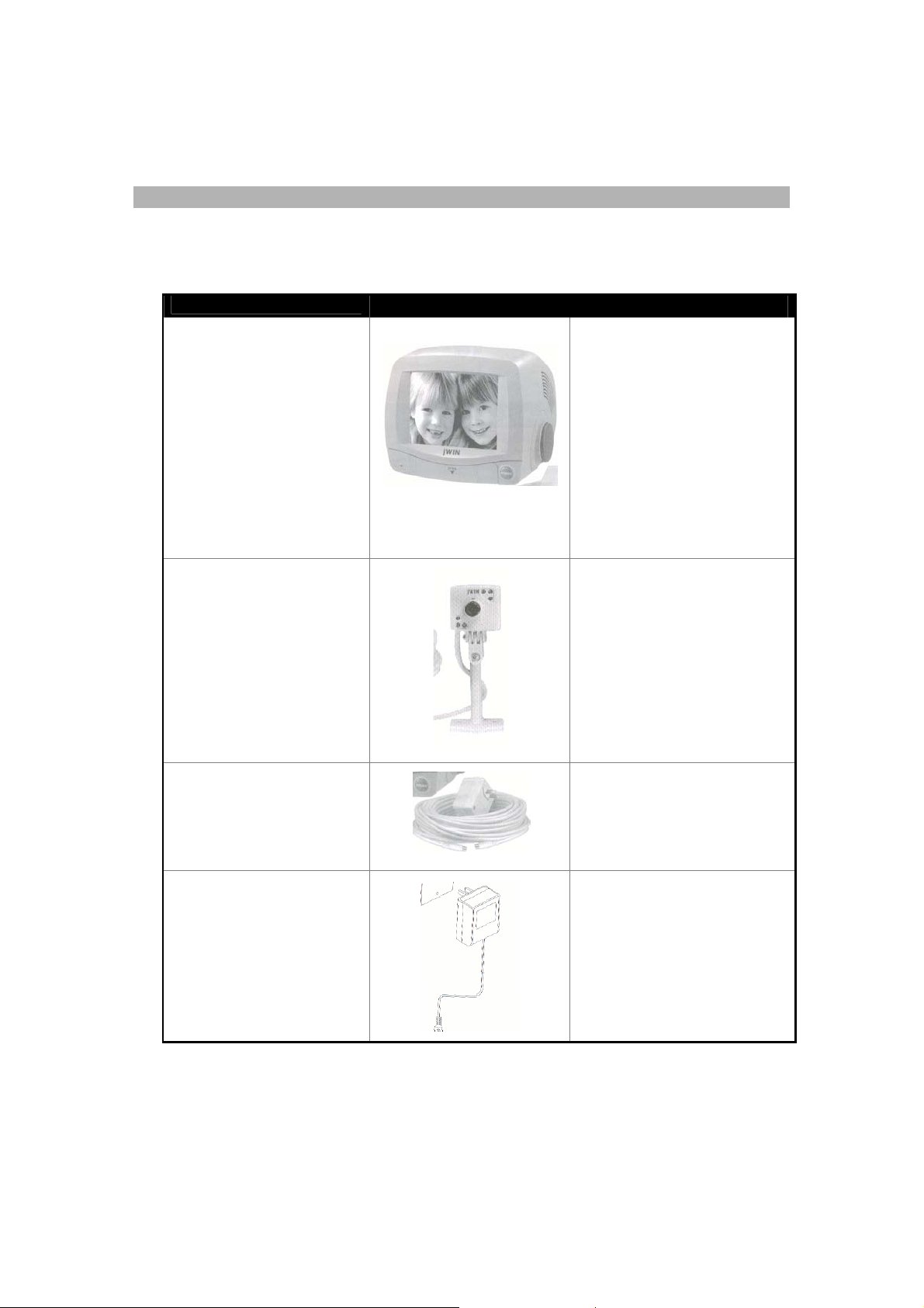
OUT OF THE BOX
After unpacking, make sure you have all the items shown below. If any are missing,
contact your dealer or retailer.
Component
Diagram Features
5.5” black & white
monitor
Weather resistant
camera with lens cover
(and two screws to
secure camera
placement)
60’ cable with DIN
plug
· High resolution
· Brightness and contrast
controls
· Two channels (for two
cameras)
· Single camera capability
· Compatibility with a
variety of camera, video
and audio outputs
· Built in two camera auto
switch
· High resolution and
sensitivity
· Low energy consumption
and excellent stabilization
· Adjustable lens
· Infrared lights that enable
clear viewing at night
· DIN connector
· Built in microphone
· High quality cable with DIN
connector and sufficient
length to facilitate
monitoring from a distance.
AC Adapter/Power Cord
-4-
· UL listed power supply
· 15V 1200mA DC power
supply
Page 5

FRONT VIEW
Volume Knob
Time Selector Knob
Power Indicator
Power ON/OFF Button
Control Panel Open/Close Point
(Press here to open)
Control Panel Door
With the control panel open, the following items are in view:
Function Switch
50/60Hz Switch
Control Panel Open/Close Fastener
-5-
Choose CH1/CH2/Auto
Page 6

Video Out Socket
REAR VIEW
AC/DC Power input
Audio Out Socket
CH1
CAMERA VIEW
Integrated
Infrared Lights
CH2
V-Hold Control
Contrast Control
Brightness Control
Infrared Lights
Microphone
Camera Bracket
DIN Connector
-6-
Page 7

PUTTING IT ALL TOGETHER
You will be pleased with the ease of installation of this unit. With just a few quick
steps, your unit will be up and running in a very short period of time.
1. Connect the camera to the monitor.
Be sure that the power cable is not connected.
a. Connect one end of the 60’ cable
to the camera cable and connect
the other end to the Channel (CH)
port on the back of the monitor as
follows:
If you are using only 1 camera:
connect the 60’ cable to the
CH1 port on the back of the
monitor.
If you are using 2 cameras:
connect the first 60’ cable to the
CH1 port on the back of the
monitor and then connect the
second cable to the CH2 port.
2. Connect the power cable:
a. Attach one end to the power connector port
on the left side of the rear of the monitor.
b. Plug the AC/DC adapter into an electrical
outlet.
That’s all there is to set up! You are now ready to start your unit and adjust the
monitor image and sound.
-7-
Page 8

Power Indicator Light
BASIC OPERATIONS
These simple steps will enable you to get the best quality sound and image on
your closed circuit monitor.
1. Push the power ON/OFF button.
The power indicator light comes on.
2. Open the control panel.
3. Move the function switch to position
“CH1” or “CH2” or Auto.
Note:
Use CH1 or CH2 when using
only 1 camera.
Use Auto when you want to use 2
cameras and switch views
according to your time setting.
Select the auto switching time.
Power ON/OFF Button
CH1/CH2/AUTO switch
Time Selector
Don’t forget to remove the
camera lens cover.
4. Set the volume
To increase volume, turn the
volume knob (found on the left
side of the unit) toward you.
To decrease volume, turn the
volume know away from you.
5. Adjust brightness, contrast, and V-
Hold to improve the image.
Brightness Control
Volume Control
Contrast Control
V-Hold Control
-8-
Page 9

VOLUME ADJUSTMENT
jWIN Security Camera has a built-in microphone that delivers high quality
The
sound. You can adjust the sound from your monitor.
To increase volume:
Turn the volume knob (found on the left side of
the unit) toward you.
To decrease volume:
Turn the volume know away from you.
Volume Control
TIME ADJUSTMENT
If you are using two cameras, you will want to adjust the timer to switch or cycle
from one view to another every few seconds.
The Time Control knob is located on the right side of the TV Monitor when you
are facing the screen. When you look at the knob, you will see that it is marked
from 2 seconds to 20 seconds in increments.
Use the knob to indicate when you want to switch
views from one camera to another.
To increase the time setting:
While facing the monitor screen turn the Time
Control knob away from you.
To decrease the time setting:
Turn the Time Control knob toward you.
Time Control
-9-
Page 10

SET UP FOR ALTERNATIVE AUDIO/VIDEO CONNECTIONS
The adaptability of the JV-TV2040 enables a variety of set-up possibilities. The
diagram below shows how you can connect a single input/camera to several
output stations. From this example, you can determine the set up that best
meets your needs.
Note:
The signal from the Audio/Video Out socket is consistent with that of the
monitor. The output can be connected to another monitor for viewing or to a
VCR for recording.
Consistent with the input video signal, please change the 50/60 Hz switch (front
control panel) to the correct position.
ONE CHANNEL INPUT CONNECTION
-10-
Page 11

TWO CHANNEL INPUT CONNECTION
If you wish to use two cameras and observe both views on one monitor, the
following set up will suit your purposes.
-11-
Page 12

SET UP FOR VCR CONNECTION
g
R
R
You can use a VCR to record the images captured by your CCTV, the following
set up will enable you to do this.
A/V OUT
A/V IN
JVTV 2040 VCR
M
UST BE IN
Click the channel
changer on the VC
until the TV shows the
same image as
JVTV2040. If your VC
has a display it will
show “Line In”.
VCR
MODE
A/V OUT
.
A/V IN
TV
Make sure your TV
shows the same
ima
e as your
JVTV20 monitor.
-12-
Page 13

TECHNICAL DATA/SPECIFICATIONS
Weight: 6.3 lbs
Mass: 10.6”x9.3”x8.6”
Monitor
Power: DC15V 1200mA
Power consumption: <20W
Camera
Resolution: 380 Horizontal TV Lines
Signal Noise Ratio: <48dB
Min Illumination: 0.5LUX
Integrated Lens: 3.6mm View Range: 78
Voltage: 12V/80mA
System: EIA
Audio Function: Audio Out
-13-
 Loading...