

Page 1
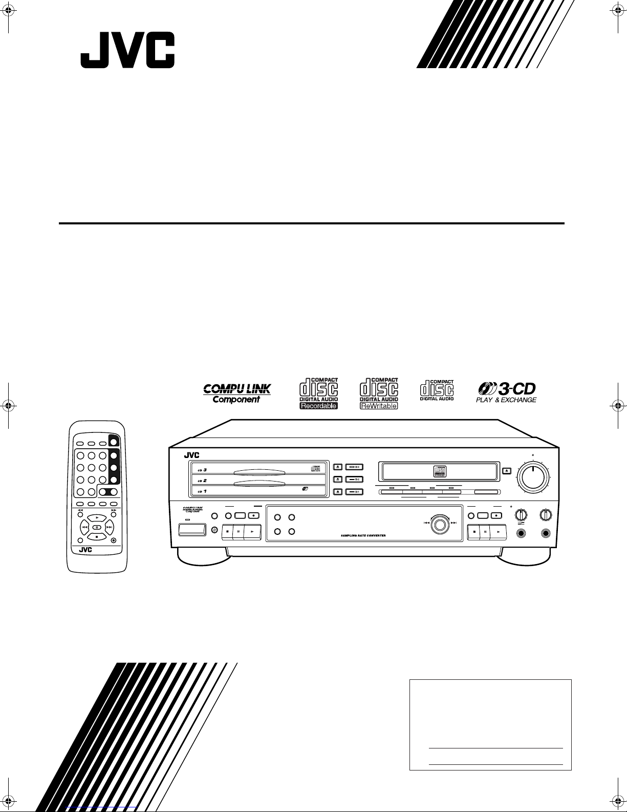
CD/CDR MULTIPLE COMPACT DISC RECORDER
XL-R5000BK
POWER
DISPLAYSYNCHROCD REC
CD EDIT FINALIZE MENU
3
9
CONTROL
CD CDR
+
10
REPEAT SET CANCEL
+
PITCH
PITCH 0
–
PITCH
REC MUTING
REMOTE CONTROL
RM-SXLR5000J
CD 1
CD 2
CD 3
REC
XL - R5000 CD/CDR MULTIPLE COMPACT DISC RECORDER
CD CONTROL
PLAY
CLOCK/
CD EDIT
MODE
TIMER
STANDBY
POWER
-
3
CD
PLAY & EXCHANGE
CD REC
DISPLAY MENU
CANCEL SET
DIGITAL
REC SOURCE SELECTOR
CD
LINE
MIXING
MIC
MULTI JOG
+–
12
456
78
10
PLAY MODE
SHIFT
MUTING
REC LEVEL
EJECT
FINALIZE
REC
SYNCHRO
REC
MIN MAX
MIX BALANCECDR CONTROL PHONES LEVEL
CD
LINE
LINE
MIC
MIC
PHONES
MAXMIN
INSTRUCTIONS
For Customer Use:
Enter below the Model No. and Serial No.
which are located on the rear, bottom or
side of the cabinet. Retain this inf ormation
for future reference.
Model No.
Serial No.
LVT0452-001C
[ J/C/B/U ]
Page 2
Warnings, Cautions and Others
For U.S.A.
This equipment has been tested and found to comply with the limits
for a Class B digital device, pursuant to part 15 of the FCC Rules.
These limits are designed to provide reasonable protection against
harmful interference in a residential installation.
This equipment generates, uses and can radiate radio frequency
energy and, if not installed and used in accordance with the
instructions, may cause harmful interference to radio
communications. However, there is no guarantee that interference
will not occur in a particular installation. If this equipment does cause
harmful interference to radio or television reception, which can be
determined by turning the equipment off and on, the user is
encouraged to try to correct the interference by one or more of the
following measures:
Reorient or relocate the receiving antenna.
Increase the separation between the equipment and receiver.
Connect the equipment into an outlet on a circuit different from that
to which the receiver is connected.
Consult the dealer or an experienced radio/TV technician for help.
CAUTION
RISK OF ELECTRIC SHOCK
DO NOT OPEN
CAUTION: TO REDUCE THE RISK OF ELECTRIC SHOCK,
DO NOT REMOVE COVER (OR BACK).
NO USER SERVICEABLE PARTS INSIDE.
REFER SERVICING TO QUALIFIED SERVICE PERSONNEL.
The lightning flash with arrowhead symbol,
within an equilateral triangle is intended to
alert the user to the presence of uninsulated
"dangerous voltage" within the product's
enclosure that may be of sufficient
magnitude to constitute a risk of electric
shock to persons.
The exclamation point within an equilateral
triangle is intended to alert the user to the
presence of important operating and
maintenance (servicing) instructions in the
literature accompanying the appliance.
IMPORTANT for the U.K.
DO NOT cut off the mains plug from this equipment. If the plug
fitted is not suitable f or the power points in y our home or the cable
is too short to reach a power point, then obtain an appropriate
safety approved extension lead or consult your dealer.
BE SURE to replace the fuse only with an identical approved
type, as originally fitted.
If nontheless the mains plug is cut off ensure to remove the fuse
and dispose of the plug immediately, to avoid a possible shock
hazard by inadvertent connection to the mains supply.
If this product is not supplied fitted with a mains plug then follow
the instructions given below:
IMPORTANT.
DO NOT make any connection to the terminal which is marked
with the letter E or by the safety earth symbol or coloured green
or green-and-yellow.
The wires in the mains lead on this product are coloured in
accordance with the following code:
Blue : Neutral
Brown : Live
As these colours may not correspond with the coloured markings
identifying the terminals in your plug proceed as follows:
The wire which is coloured blue must be connected to the
terminal which is marked with the letter N or coloured black.
The wire which is coloured brown must be connected to the
terminal which is marked with the letter L or coloured red.
IF IN DOUBT - CONSULT A COMPETENT ELECTRICIAN.
WARNING: TO REDUCE THE RISK OF FIRE
OR ELECTRIC SHOCK, DO NOT EXPOSE
THIS APPLIANCE TO RAIN OR MOISTURE.
G-1
Page 3
CAUTION
For Canada & USA
Caution –– POWER switch!
Disconnect the mains plug to shut the power off completely. The
POWER switch in any position does not disconnect the mains
line. The power can be remote controlled.
Attention –– Commutateur POWER!
Déconnecter la fiche de secteur pour couper complètement le
courant. Le commutateur POWER ne coupe jamais
complètement la ligne de secteur, quelle que soit sa position. Le
courant peut être télécommandé modèle.
For other countries
Caution –– switch!
Disconnect the mains plug to shut the power off completely. The
switch in any position does not disconnect the mains line. The
power can be remote controlled.
For Canada/pour le Canada
THIS DIGITAL APPARATUS DOES NOT EXCEED THE CLASS B
LIMITS FOR RADIO NOISE EMISSIONS FROM DIGITAL
APPARATUS AS SET OUT IN THE INTERFERENCE-CAUSING
EQUIPMENT STANDARD ENTITLED "DIGITAL APPARATUS",
ICES-003 OF THE DEPARTMENT OF COMMUNICATIONS.
CET APPAREIL NUMERIQUE RESPECTE LES LIMITES DE
BRUITS RADIOELECTRIQUES APPLICABLES AUX APPAREILS
NUMERIQUES DE CLASSE B PRESCRITES DANS LA NORME
SUR LE MATERIEL BROUILLEUR: "APPAREILS NUMERIQUES",
NMB-003 EDICTEE PAR LE MINISTRE DES COMMUNICATIONS.
To reduce the risk of electrical shocks, fire, etc.:
1. Do not remove screws, covers or cabinet.
2. Do not expose this appliance to rain or moisture.
ATTENTION
Afin d'éviter tout risque d'électrocution, d'incendie, etc.:
1. Ne pas enlever les vis ni les panneaux et ne pas ouvrir le coffret
de l'appareil.
2. Ne pas exposer l'appareil à la pluie ni à l'humidité.
For Canada/pour le Canada
CAUTION: TO PREVENT ELECTRIC SHOCK, MATCH WIDE
BLADE OF PLUG TO WIDE SLOT, FULLY INSERT
ATTENTION: POUR EVITER LES CHOCS ELECTRIQUES,
INTRODUIRE LA LAME LA PLUS LARGE DE LA FICHE DANS LA
BORNE CORRESPONDANTE DE LA PRISE ET POUSSER
JUSQUAU FOND
G-2
Page 4
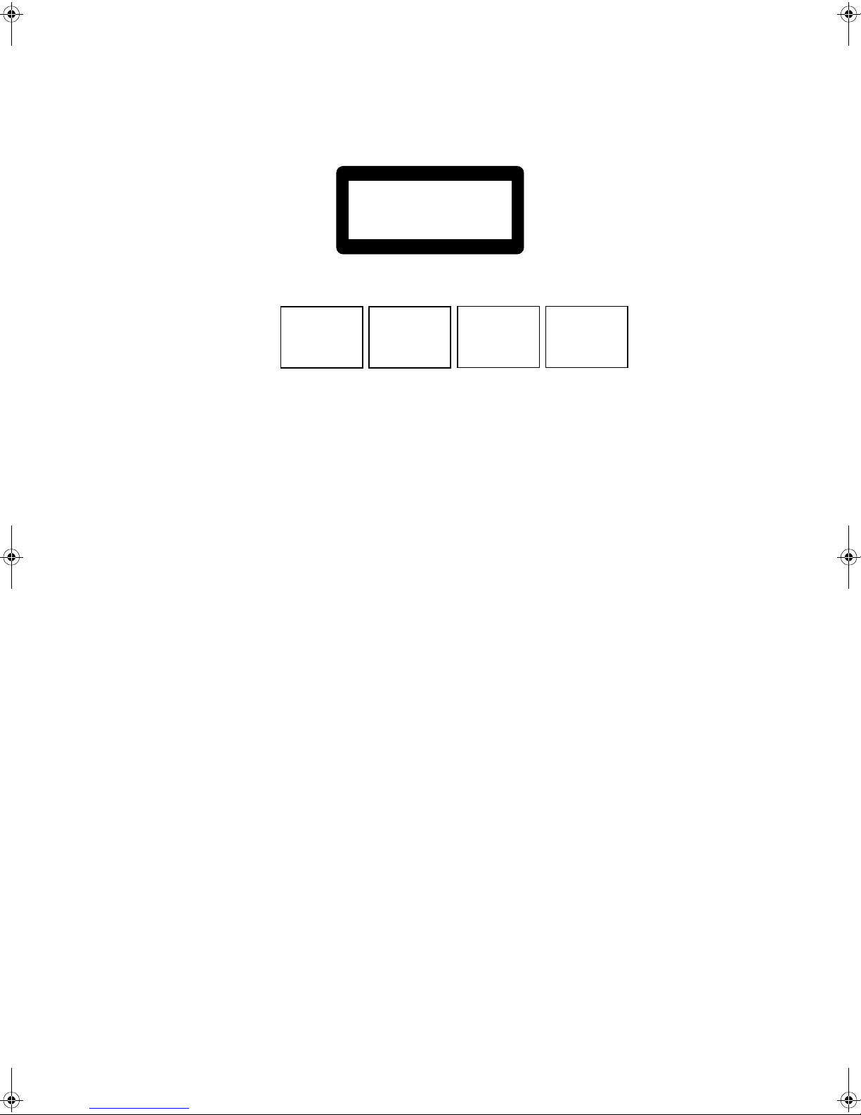
REPRODUCTION OF LABELS (Except for Canada & USA)
1 CLASSIFICATION LABEL, PLACED ON REAR ENCLOSURE
CLASS 1
LASER PRODUCT
2 WARNING LABEL, PLA CED INSIDE THE UNIT
CAUTION: Invisible laser
radiation when open and
interlock failed or defeated.
AVOID DIRECT EXPOSURE
TO BEAM. (e)
VARNING: Osynlig laserstrålning när denna del är
öppnad och spärren är
urkopplad. Betrakta ej
strålen. (s)
ADVARSEL: Usynlig laserstråling ved åbning, når
sikkerhedsafbrydere er ude
af funktion. Undgå udsættelse for stråling (d)
VARO: Avattaessa ja suojalukitus ohitettaessa olet
alttiina näkymättömälle
lasersäteilylle. Älä katso
säteeseen. (f)
IMPORTANT FOR LASER PRODUCTS
IMPORTANT POUR LES PRODUITS LASER
(For Canada & USA)
1. CLASS 1 LASER PRODUCT
2. DANGER: Invisible laser radiation when open and interlock failed or
defeated. Avoid direct exposure to beam.
3. CAUTION: Do not open the top cover. There are no user serviceable
parts inside the Unit; leave all servicing to qualified service
personnel.
1. PRODUIT LASER CLASSE 1
2. ATTENTION: Radiation laser visible quand l’appareil est ouvert ou
que le verrouillage est en panne ou désactivé. Eviter une exposition
directe au rayon.
3. ATTENTION: Ne pa s ouvrir le couvercle du dessus. Il n'y a aucune
pièce utilisable à l'intérieur. Laisser à un personnel qualifi é le soin de
réparer votre appareil.
(For other countries)
1. CLASS 1 LASER PRODUCT
2. CAUTION: Invisible laser radiation when open and interlock failed or
defeated. Avoid direct exposure to beam.
3. CAUTION: Do not open the top cover. There are no user serviceable
parts inside the Unit; leave all servicing to qualified service
personnel.
G-3
Page 5
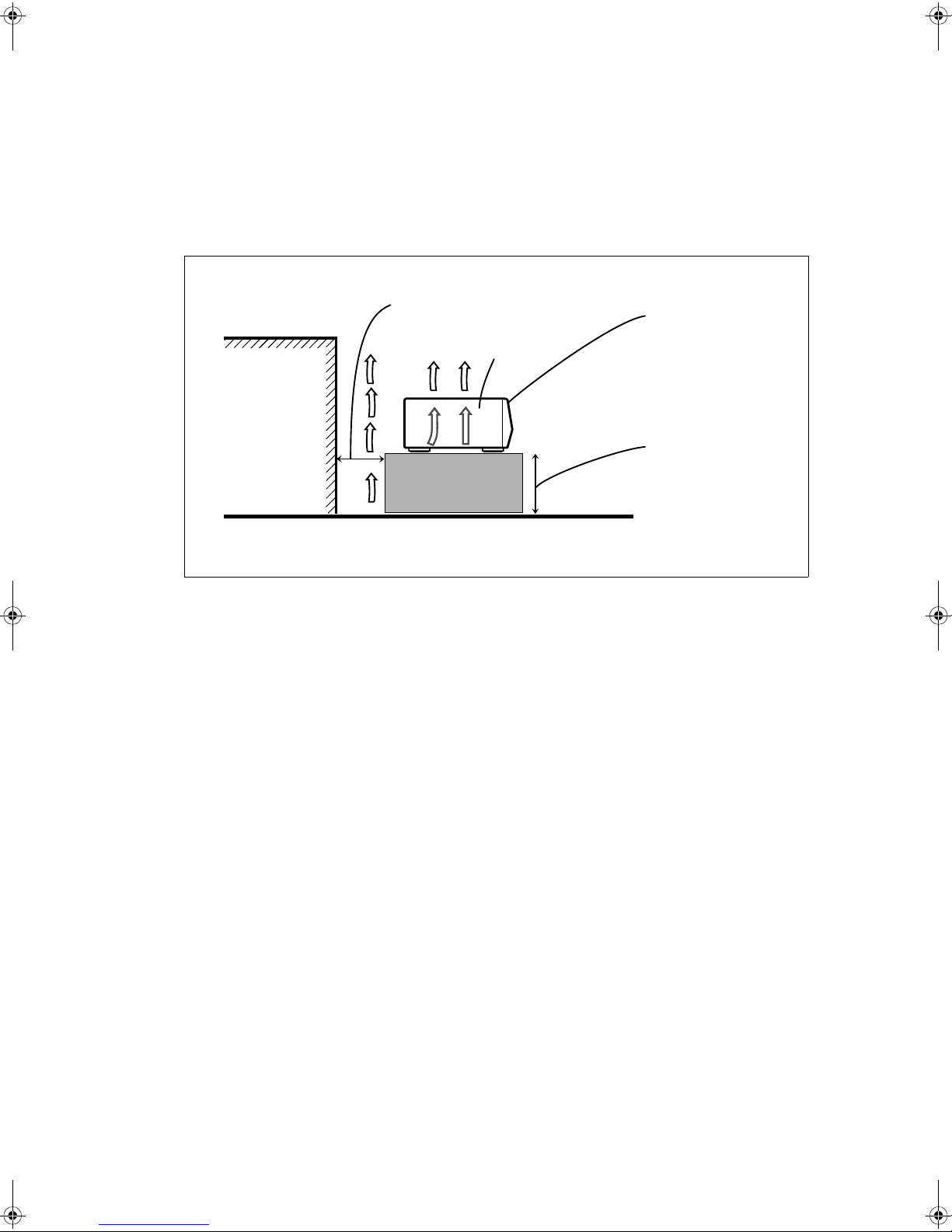
Caution: Proper Ventilation
To avoide risk of electric shock and fire and to protect from damage.
Locate the apparatus as follows:
Front: No obstructions open spacing.
Sides: No obstructions in 3 cm from the sides.
Top: No obstructions in 5 cm from the top.
Back: No obstructions in 15 cm from the back
Bottom: No obstructions, place on the level surface.
Spacing 15 cm or more
XL-R5000BK
Wall or obstructions
Floor
Front
Stand height 15 cm or more
G-4
Page 6

Table of Contents
Introduction .......................................................1
Table of Contents ..............................................1
Precautions ........................................................ 2
Features .............................................................2
Connections ....................................................... 3
Analog Connections....................................................................3
Digital Connections.....................................................................4
Names of the Parts ............................................5
Main Unit....................................................................................5
Display Window..........................................................................7
Remote Control...........................................................................8
Using the Remote Control ................................9
Installing the batteries.................................................................9
How to use the remote control correctly.....................................9
Power ON/STANDBY Operations ................10
Turning the power on and putting in standby...........................10
Listening to CDs ..............................................11
Continuous Playback of the 3-CD Changer (playing
the loaded discs through once each)......................................11
CDR Playback Operations........................................................12
Using the Remote Control to Control Playback........................12
Direct Playback from a Specific Track.....................................13
Forward and Reverse Search....................... ............................. .13
Skipping Tracks ........................................................................14
Repeat Playback........................................................................14
Random Playback......................................................................15
CD Playback Pitch Control.......................................................15
Disc Lock Function...................................................................1 5
Program Playback.....................................................................16
Program playback using the remote control..............................17
Recording onto CD-R and CD-RW ...............18
Manual Recording.....................................................................18
Synchronized Recording of 3-CD Changer Playback...............20
Listening Edit Recording..........................................................21
Program Edit Recording............................................................22
3-CD Changer to CDR Recording Options...............................23
Setting the unit to perform high-speed recordin g.....................23
Setting the auto track spacing function.....................................24
Synchronized Start Recording of External Components ..........25
Mixed Input Recording................................... ... .... ...................26
Special Recording Edit Operations ..............27
Skipping a Recorded Track on a CD-R or CD-RW
(Track Skip)...........................................................................27
Erasing a track or tracks (ERASE function).............................27
Erasing all the tracks (DISC ERASE function) ........................28
Finalization................................................................................29
Making recording possible again on a finalized CD-RW
(UNFINALIZE function)......................................................30
Bypassing the FS Converter (Sampling Frequency Converter)
for More Efficient Digital Recording....................................30
Setting Up Synchronized Start Recording for External
Digital Sources (CD, MD, and DAT only) ...........................31
Resetting the Unit to the Factory Default Settings....................32
Setting the Clock .............................................33
Setting the Present Time ...........................................................33
Timer Operations ............................................34
Timer Play (wake-up play)........................................................34
Timer Recording (unattended reco rding of the sound from a
broadcast receiver or other component)................................35
COMPU LINK Function ................................37
CD and CDR Messages ...................................38
Restriction on Copying Digital Material .......40
SCMS (Serial Copy Management System) ...............................40
Troubleshooting ..............................................41
Main Specifications .........................................42
1
Page 7
Precautions
Features
Thank you for purchasing this JVC product. Please read these
instructions through carefully before starting operation to ensure
that you will derive the optim um performance and a long service
life from your unit .
Safeguarding against electric shocks, fire hazards
and damage
1) A very low current will still flow even when the POWER (for
Canada and U.S.A.)/ (for other countries) button is set at
STANDBY. To save power and ensure safety when the unit is
not going to be used f or an e xtended period of time , dis c on ne c t
the power co rds f rom the hou s ehold AC outlet. (Se e pa g e 10 )
2) Do not handle the power cord with wet hands.
3) To unplug the power cord from the household AC outlet,
always take hold of the molded plug part and pull the plug free
rather than pulling the cord.
4) If the power cord is damaged or found to have a disconnected
wire or a contact failure, consult your dealer.
5) Do not bend the cor d a t a s har p an gle, and do not pull or twist it.
6) Do not modify the power cord in any way.
7) Do not remove the screws in order to disassemble the unit, and
do not touch any of the parts inside the unit.
8) Do not insert metallic objects into the unit.
9) Unplug the power cord during electrica l storms.
10) If water should find its way inside the unit, unplug the power
cord from the outlet, and consult your dealer.
11) Do not install the unit in a poorly ventilated location.
Installation
1) Avoid placing the unit on or adjacent to an amplifier. This is to
prevent the humming caused by the unit’s proximity to some
types of amplifiers. Move the unit where it will not be affected
by the amplifier.
2) Avoid installing the unit where the ambient temperature will
exceed 35 °C (namely, in direct sunlight, near a hea ting appli ance, etc.) or drop below 5 °C, where it is very humid or dusty,
or where the unit will be subject to vibration.
3) The unit may not function properly if it is moved suddenly from
a cold place (0 °C) to a warm place since condensation may form
inside the unit. In such a case, leave the unit standing for about
couple of hours, after which time it s hou ld f unc tion p rope rly.
Disc care
• Storing CDs
• Always ensure that each CD is stored in its own case.
• Do not place CDs in direct sunlight, near a heating appliance
or any other location which is susceptible to high temperatures.
• If cellophane tape , an adhesive sticker or some other form of
glue is present on the label side, clean it off before use.
• Do not stick adhesive labels or write anything on a CD.
• Do not bend CDs.
• Do NOT insert shaped CDs, such as CDs in a heart, flower or
other shape, because their shape does not match the shape of the
CD tray, and using them will give rise to malfunctioning.
Cleaning the cabinet
Never use benzine or paint thinners to clean the cabinet as they
may mar the unit’s surface finish.
All of the functions and co nveniences of having a 3-CD changer
and CDR in a single combination deck
• 3-CD changer compatible with CD-RW
• CDR capable of performing high speed (2x) recording of
discs loaded in the 3-CD changer
• Optical digital/analog input and output with an additional
input for microphone
• Sampli ng frequ ency c onverter capable o f convert ing dig ital signals wit h sa mpli ng fr equen cy of 32 kHz and 4 8 kHz
to digital signa ls wit h a sampling frequency of 44.1 kHz for
quality recording from a variety of sources
• No sampling frequency conversion of 44.1 kHz signals for
optimal reco rding of CDs
• Mixing and recording of the 3-CD changer playback and
either micro phone input or an exter nally input source, or
even the microphone input and the externally input source
• Many convenient recording options including: one-button
CD and single tra c k reco rding, L isteni ng and Progr am Edi t
recording, manual recording, synchronized start recording, and mixed input recording
• CD playback pitch control that can adjust the speed of play
up to 12% faster or slower than the normal speed to alter
the pitch for singing along to or other customized uses
• Timer playback and timer recording that can be set for
one-time or ev eryday operation
• OPC (Opt imize Power Control), stre ngth adjust ment performed for best possible rec ord ing o nto C D-R and C D-RW
media
Types of Discs Compatible with the Unit
The following disc formats can be used in the CDR for
recording.
In addition to the marks shown above, the phrases
shown below or their equivalent should also be present
somewhere on the packaging or accompanying documentation:
FOR CONSUMER
FOR CONSUMER USE
FOR MUSIC USE ONLY
Discs that cannot be used for recording are as follows:
• Discs bearing marks other than those shown above
• Discs intended for professional use and/or marked
“FOR PROFESSIONAL USE ONLY”
• Discs intended for recording computer data
In addition to the two disc formats shown above, the following disc format can also be played in either the 3CD
changer or CDR.
Notes
• Although the CDR can play all 3 types of discs at any time, the
3-CD changer can only play CD-R and CD-RW after they have
been finalized. For more information on finalization of CD-R
and CD-RW, see page 29.
• The unit can playback audio recorded in CD-G, CD-EXTRA
and CD-Text discs.
• If a CD-R or CD-RW has been recorded using a personal computer, playback is only possible if the disc is recorded in the CD
Audio format.
English
2
Page 8
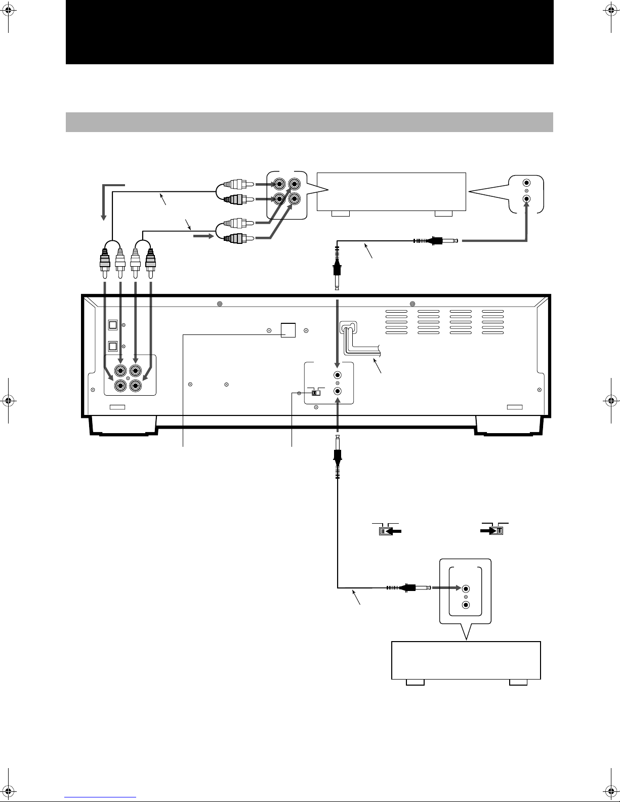
Connections
Do not turn on the power until all the connections have been completed.
Analog Connections
Use the accessory pin cables to connect this unit’s LINE connectors with the TAPE/CDR connectors on the receiver, etc.
Recording signals
(line input)
Accessory pin cables
Playback signals
DIGITAL IN
OPTICAL
DIGITAL OUT
OPTICAL
LINE
( )
( )
OUT PLAY
IN REC
LEFTLEFT
RIGHTRIGHT
Units have a voltage selector excluding units for
Canada, Europe, and U.S.A.
TAPE
/CDR
OUT
IN
(REC)
(PLAY)
VOLTAGE SELECTOR
CDR TD
MODE switch
COMPU LINK
(SYNCHRO)
MODE
Amplifier, receiver etc.
made by JVC
Accessory connecting cable
(with black plugs)
XL-R5000 CD/CDR MULTIPLE
COMPACT DISC RECORDER
-
4
Power cord
Selecting the MODE switch position
• W hen connec ted with
CDR input/output
terminals of the amplifier
or receiver
MODE
CDR
TD
• W hen connec ted with
TAPE input/output
terminals of the amplifier
or receiver
CDR
MODE
TD
-
COMPU LINK
SYNCHRO
4
Note
• Before selecting the COMPU LINK-4 mode (CDR or TD), disconnect the power cord from the power outlet to turn off the
power. The function will not be set if it is selected while the
power is on.
Alternatively, when the COMPU LINK-4 mode (CDR or TD) is
selected while the power is on, disconnect th e power cord and
then re-connect it.
• Misconnecti ons can be avoided by using t he white plugs on t he
accessory pin cables for the LEFT channel and the red plugs for
the RIGHT channel.
• Insert the plugs all the way in. Incomplete connections may
cause noise.
• When plugging the power cord into the AC outlet, be sure to
match the width of the plug blades with the outlet.
3
• For fur ther details on the COMPU LINK function, see
page 37.
-
COMPU LINK
SYNCHRO
3
Optional connecting cable
CD player, cassette deck or
other component made by JVC
Page 9
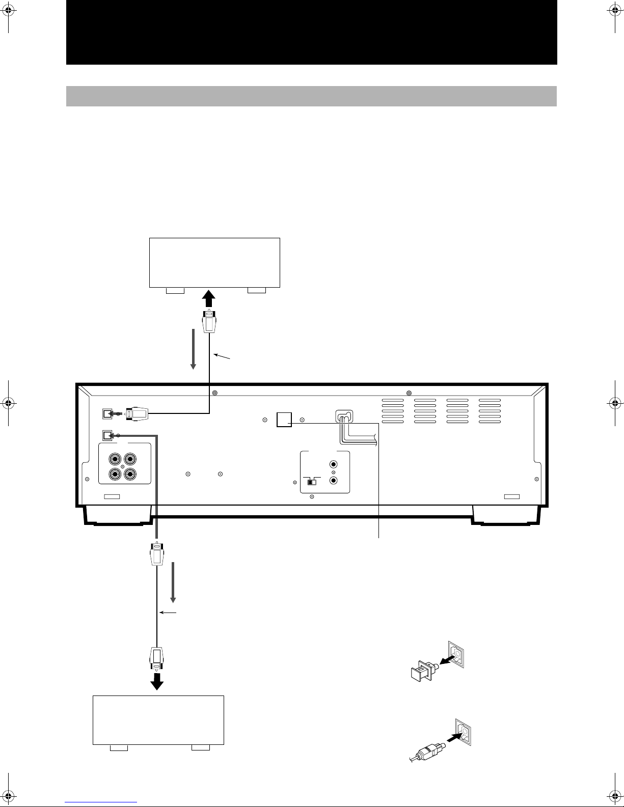
Digital Connections
English
Before proceeding, check whether the optical
digital cable can be connected.
• Connect a receiver or amplifier with digital audio capability to
the DIGITAL OPTICAL connectors on this unit.
• One connecting cable is used to transmit the s tereo signals (L/
R) as a digital signal.
CD player, etc.
To OPTICAL OUTPUT connector
Optional optical digital cable
Input signal
DIGITAL IN
OPTICAL
DIGITAL OUT
OPTICAL
( )
IN REC
LINE
OUT PLAY
( )
LEFTLEFT
RIGHTRIGHT
VOLTAGE SELECTOR
• If analog a udio co nnections are al so being m ade, t ry to u se the
digital connectors on the receiver or amplifier that are labeled
the same way as the analog connectors.
• Before pur chasing an opti cal digital cable (optional), make sure
that the cable in question can be connected to the ampli fier, etc.
• Do not bend the optical digital cable at a sharp angle.
• When the power is turned on, the inside of the connector lights
up red. This light is for sending the digital signals. Although
this light will not harm your eyes, keep the protective cap in
place if the connector is not going to be used.
XL-R5000 CD/CDR MULTIPLE
COMPACT DISC RECORDER
-
4
COMPU LINK
(SYNCHRO)
MODE
CDR TD
To DIGITAL
OUT OPTICAL
connector
Output signal
Optional
optical digital
cable
To OPTICAL INPUT connector
Receiver or amplifier with
digital OPTICAL connector
Units have a voltage selector excluding units for
Canada, Europe, and U .S.A.
How to use the OPTICAL connectors for the
connections
1 Remove the protective cap.
• When the conn ector is not go ing to be used, fit this protective
cap back in position.
2 Check that the end of the optical digital cable is
not dirty, and insert it securely.
4
Page 10
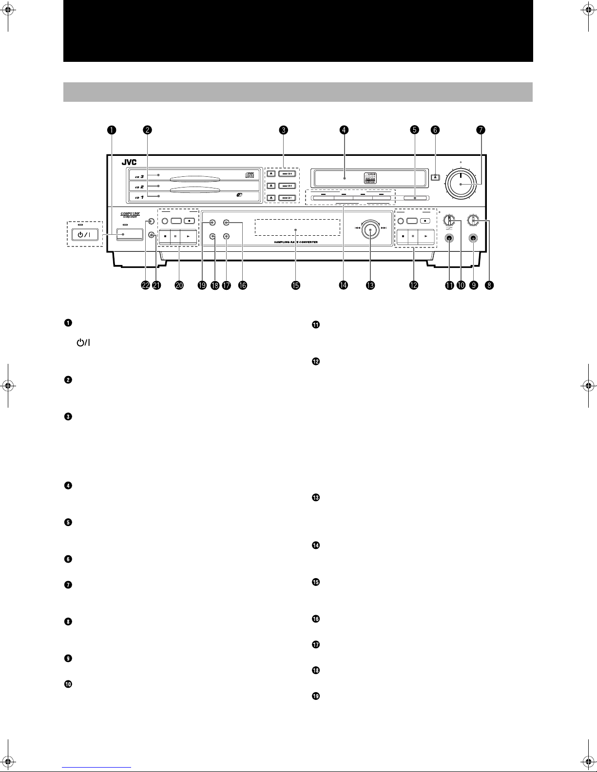
Names of the Parts
Main Unit
XL - R5000 CD/CDR MULTIPLE COMPACT DISC RECORDER
-
3
CD
PLAY & EXCHANGE
CD CONTROL
PLAY
CLOCK/
CD EDIT
CD REC
MODE
STANDBY/ON
STANDBY
TIMER
STANDBY
POWER
DISPLAY MENU
CANCEL SET
POWER button and STANDBY lamp (for Canada and
U.S.A)
button and STANDBY lamp (for other countries)
Press to turn the power on or to put in standby. When the unit is in
standby, the STANDBY lamp is lit. (See page 10.)
CD trays 1, 2, and 3 (numbered from bottom to top)
Load CDs on these trays for 3 -CD changer playback. (See page
11.)
Disc tray selector buttons (with current selection
lamp) and 0 (eject) buttons
Press to select one of the CDs loaded in the 3-CD changer. The
lamp on the button lights to indicate the cur rently selec ted tray. Use
the 0 (eject) buttons to open and close the corresponding disc
trays. (See page 11.)
CDR disc tray
Load a recordable CD-R or CD-RW in this tray for recording. CD
playback is also available using this tray.
FINALIZE button
Press to finalize a CD-R or CD-RW disc when recording on the
disc has been completed. (See page 29.)
EJECT 0
Press to open and close the CDR disc tray.
REC LEVEL control and lamp
Use to adjust the level of the source sign al being recorded. (See
page 18 and 25.)
PHONES LEVEL control
Use to adjust the level of the volume being output to connected
headphones (not supplied).
PHONES connector
Use to connect headphones (not supplied) to this unit.
MIX BALANCE control and lamp
Use to control the mixing levels of two independent sources being
recorded. The lamp is lit during mixed recording. (See page 26.)
REC LEVEL
EJECT
REC SOURCE SELECTOR
DIGITAL
LINE
CD
MIXING
MIC
MULTI JOG
FINALIZE
REC
MUTING
SYNCHRO
+–
REC
MIN MAX
MIX BALANCECDR CONTROL PHONES LEVEL
CD
LINE
LINE
MIC
MIC
PHONES
MAXMIN
MIC connector
Use to connect a microphon e (not su pplied) t o this un it. (See page
18.)
CDR CONTROL operation buttons
REC MUTING: Press to record silence during a recording. (See
page 19.)
SYNCHRO: Press to select synchron ized start recording. (S ee
page 25.)
REC ¶: Press to put this unit in record pause mode for
manual recording. (See page 18 and 26.)
7 (stop): Press to stop recording or play of the CDR. (See
page 12 and 19.)
8 (pause): Press to pause play and recording. (S ee page 12.)
3 (play): Press to start play or recording (in record pause
mode) of the CDR. (See page 12 and 19.)
MULTI JOG dial
Depending on the mo de, use to skip for ward or bac kward through
tracks on a CD, change the clock settings, or select setting options.
(See pages 14, 16, 23, and 33.)
REC SOURCE SELECTOR buttons
Use to select the type of sourc e to be rec orded. (See p ages 18 an d
26.)
Display window
Displays the operation mo des and other system informat ion. (See
page 7.)
MENU button
Press to enter a menu option.
SET button
Press to enter a selection.
CANCEL button
Press to cancel an operat ion.
DISPLAY button
Press repeatedly to ch ange the type of information that ap pears in
the display window information display.
5
Page 11

CD CONTROL operation buttons
PLAY MODE: Press repeatedly to select one of the play modes for
the 3-CD changer. (See page 15 and 16.)
CD EDIT: Press to select either the Listening Edit or Program
Edit recording modes. (See page 21 and 22.)
CD REC: Press to perform synchronized recording of the
currently selected CD in the 3-CD changer. (See
page 20 and 21.)
7 (stop): Press to stop play of the selected disc in the 3-CD
changer. (See page 11.)
8 (pause): Press to pause play of the selected disc in the 3-CD
changer. (See page 11.)
3 (play): Press to st art play of the selected di sc in the 3-CD
changer. (See page 11.)
Remote control sensor
Receives commands from the remote control.
CLOCK/TIMER button
Use to set the time. (See page 33.)
English
6
Page 12
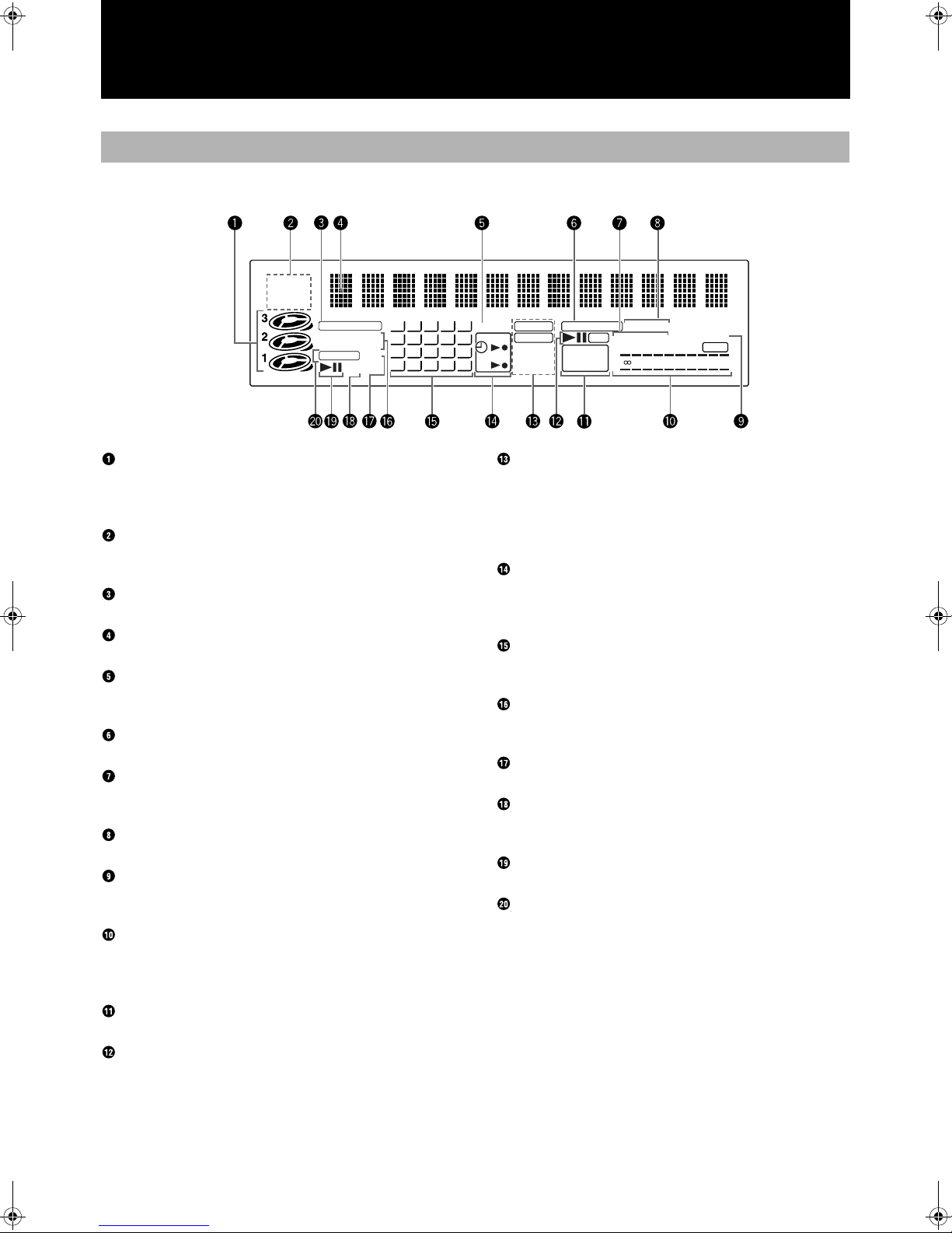
Display Window
PROGRAM
ALL 1CD
RANDOM
REPEAT
CD PLAYER
LISTENING EDIT
PROGRAM EDIT
CD REC 1CD
–
PITCH
12345
678910
11 12 13 14 15
16 17 18 19 20
+
SKIP ON
ANALOG CD RECORDER
DIGITAL
DAIL Y
32kHz
ONCE
44.1kHz
48kHz
HIGH SPEED AUTO TRACK
REC
CD CD-R
L
CD–RW
FINALIZED
–
R
SYNCHRO
OVER
4030 20 1510 dB630
CD numbers and play status displays
Indicate whether discs are load ed in any of the 3-CD chan ger disc
trays, which disc is currently selected, an d the operation status of
the current disc. (See page 12.)
PLAY MODE indicators
Light according to which play mode has been selected. (See page
14 to 16.)
CD PLAYER indicator
Lights when the 3-CD changer is selected for play.
Information display
Displays track, time, and operation information.
SKIP ON indicator
Lights when the currently selected disc contains SKIP TRACK
markers.
CD RECORDER indicator
Lights when the CDR has been selected for play or recording.
HIGH SPEED indicator
Lights when the high speed (2x) dubbing function is being performed. (See page 23.)
Synchronized recording indicators
Light to indicate synchronized recording is on. (See page 20.)
AUTO TRACK indicator
Lights when automatic track marking has been turned on. (See
page 18.)
Level meter
Indicates the level of the right and left channels during playback
and recording operation s. When the in put sign al exceeds 0 dB, the
OVER indicator lights. (See page 18.)
Disc format indicators
Light to indicate the type of disc that is loaded in the CDR.
CDR deck operation indicators
Light to indicate the operation mode of the CDR.
Recording type indicators and sampling frequency
indicators
Light to indicate whether the recording is analog or digital. During
digital recording, the appropriate frequen c y ind icat or lights to ind icate the sampling frequency of the source being recorded. (See
page 18.)
Timer operation indicators
Indicate that a Timer Play or Timer Recording funct ion has been
set, and whether it is set for everyday or one-time operation. (See
pages 33.)
Music calendar
Indicates the number of tracks on the currently selected CD or
CDR, and the track on the disc that is being playe d or recorded.
EDIT recording indicators
Indicates whether the Listening Edit or Program Edit functions are
being performed. (See pages 21 and 22.)
1CD indicator
Lights during synchronized recording. (See page 20.)
PITCH (+/–) indicators
Indicate that the pitch of CD pl ay has been adjusted in on e direction or the other. (See page 15.)
3-CD changer operation indicators
Light to indicate the operation mod e of the 3-CD chan ge r.
CD REC indicator
Indicates the CD(s) loaded in the 3-CD changer is being recorded
by the CDR.
7
Page 13
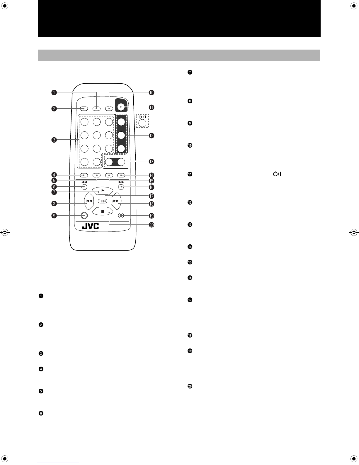
Remote Control
POWER
CD EDIT FINALIZE MENU
12
4
78
10
PLAY MODE
SHIFT
When performing the procedures in this manual,
the buttons on the remote control have the same
function as the corresponding buttons on the main
unit.
SYNCHRO/FINALIZE button
Press to select synchronized start recording. (See page 25.)
When SHIFT is pressed down, press to start finalization of a CD-R
or CD-RW. (See page 29.)
CD REC/CD EDIT button
Press to start the CD REC function. (See pages 21.)
When SHIFT is pressed down, press repeatedly to select Listening
Edit or Program Edit functions. (See pages 21 and 22.)
Number buttons
Press to select a track for playback. (See page 13.)
PLAY MODE button
Press repeatedly to select a play mode for the 3-CD changer. (See
page 15.)
REPEAT button
Press repeatedly to select one o f the repeat play modes. (See page
14.)
1 (reverse) button
Press to perform fast reverse search of the currently selected CD.
(See page 13.)
DISPLAYSYNCHROCD REC
CD 1
3
CD 2
6
5
CD 3
9
CONTROL
CD CDR
+
10
REPEAT SET CANCEL
+
PITCH
PITCH 0
PITCH
REC
–
REC MUTING
REMOTE CONTROL
RM-SXLR5000J
3 (play)/PITCH + button
Press to play the currently selected CD. (See page 10 and 12.)
When SHIFT is pressed down, press to raise the pitch of CD playback. (See page 15.)
4 (skip reverse) button
Press to skip back to th e beginning of previous tracks. ( See page
14.)
SHIFT button
Press down in conjun ct ion with oth er buttons on the remote control
to make use of their secondary functions.
DISPLAY/MENU button
Press repeatedly to ch ange the type of information that ap pears in
the display window information display.
When SHIFT is pressed down, press to enter a menu opt ion.
POWER (for Canada and U.S.A.)/
(for other
countries) button
Press to turn the power of thi s unit on or to put in standby. (See
page 10.)
CD1, CD2, and CD3 disc selection buttons
Use to select one of the discs loaded in the 3-CD changer. (See
page 10,12, and 13.)
CD and CDR deck selection buttons
Press to change the function of this unit to the 3-CD changer or
CDR. (See page 12.)
CANCEL button
Press to cancel an operat ion.
SET button
Press to enter a selection.
¡ (forward) button
Press to perform fast forward search of the currently selected CD.
(See page 13.)
8 (pause)/ PITCH 0 button
Press to pause playbac k of the currently selected disc. (See page
12.)
When SHIFT is pressed down, press to restore the pitch level of
CD playback. (See page 15.)
¢ (skip forward) button
Press to skip forward to ot her tracks on the disc. (See page 14.)
REC ¶/REC MUTING button
Press to put this unit in the record pause mode. (See page 18 and
26.)
When SHIFT is pressed down, press to record silence during a
recording. (See page 19.)
7 (stop)/PITCH - button
Press to stop playback of the currently selected disc. (See page 12.)
When SHIFT is pressed down, press to lower the pitch level of CD
playback. (See page 15.)
English
8
Page 14
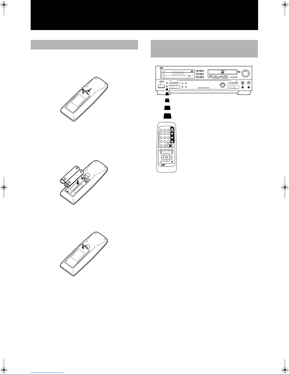
Using the Remote Control
Installing the batteries
1 Press down on the point shown by the arrow at
the top of the compartment cover, and pull up
the cover to open the compartment.
2 Place the two accessory AA (15F), R6, SUM-3
batteries in the remote control making sure to
align the polarity markings (“+” and “–”) inside
the compartment and on the batteries.
How to use the remote control
correctly
XL - R5000 CD/CDR MULTIPLE COMPACT DISC RECORDER
PLAY
CLOCK/
MODE
TIMER
STANDBY
POWER
DISPLAYSYNCHROCD REC
CD EDIT FINALIZE MENU
12
3
456
9
78
CONTROL
CD CDR
+
10
10
PLAY MODE
REPEAT SET CANCEL
+
PITCH
PITCH 0
–
PITCH
SHIFT
REC MUTING
REMOTE CONTROL
RM-SXLR5000J
-
3
CD
CD CONTROL
CD EDIT
POWER
CD 1
CD 2
CD 3
REC
PLAY & EXCHANGE
CD REC
DISPLAY MENU
CANCEL SET
REC SOURCE SELECTOR
DIGITAL
LINE
CD
MIC
MIXING
MUTING
MULTI JOG
+–
REC LEVEL
EJECT
FINALIZE
REC
SYNCHRO
REC
MIX BALANCECDR CONTROL PHONES LEVEL
CD
LINE
LINE
MIC
MIC
MAXMIN
PHONES
MAXMIN
3 Place the cover over the compartment, and
press down lightly.
• Point the remot e control correctly at the remote cont rol sensor
on the main unit when pressing the buttons.
• The remote control can be operated at a distance of up to 7
meters or so from the remote control sensor. This distance will
be less if the remote control is operated from a position whic h is
not directly in front or on the same level as the main unit.
• When the distance over which the remote control can be operated starts to drop, it means that the batteries are nearing the end
of their service life.
• Replace both batteries (AA (15F), R6, SUM-3) with fresh units.
• The dry batteries provided with the unit are for operational
check purposes. Replace t hem with fresh units at the earliest
opportunity.
• Do not drop the remote control or subject it to strong impact.
• In order to ensure that the remote control does not fail to operate, avoid operation under the following conditions:
• When the remo te control sensor is exposed to dire ct sunlight
or other intense source s of lig ht
• When objects in front of the remote control sensor block the
transmission of signals from the remote control
9
Page 15
Power ON/STANDBY Operations
Turning the power on and
putting in standby
XL - R5000 CD/CDR MULTIPLE COMPACT DISC RECORDER
MIX BALANCE
STANDBY
PHONES LEVEL
MAXMIN
MULTI JOG
+–
POWER
REC LEVEL
12
3
4
5
6
78
10
+
10
9
PLAY MODE
REPEAT SET CANCEL
CONTROL
PITCH 0
PITCH
+
PITCH
–
SHIFT
REMOTE CONTROL
RM-SXLR5000J
REC MUTING
REC
DISPLAYSYNCHROCD REC
CD EDIT FINALIZE MENU
POWER
CD 1
CD 2
CD 3
CD CDR
CD1, CD2, CD3
POWER
()
POWER ( )
CD1, CD2, CD3
3
3
3
0
0
Lamp goes out.
Main Unit
Remote Control
Main Unit
Remote Control
For Canada and U.S.A.
Lamp goes out.
For other countries.
Lamp lights
Main Unit
Remote Control
Main Unit
Remote Control
For Canada and U.S.A.
Lamp lights
For other countries.
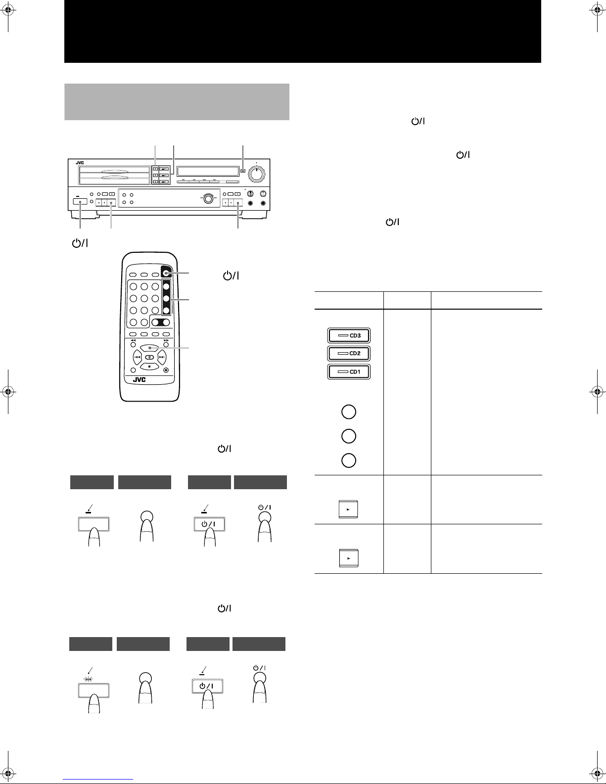
To turn on the power
Press the POWER (for Canada and U.S.A.)/ (for other countries) button on the front panel or remote control.
• The clock displ ay appears in the display wi ndow. It flashes if
the clock has not been set.
• The power can only be put to sta ndby by pressing t he POWER
(for Canada and U.S.A.)/ (for other countries) button press-
ing.
If the POWER (for Canada and U.S.A.)/ (for other countries)
button is pressed during recor ding, the standby l amp flashes while
the unit brings the oper ation to a stop . Once t he unit ha s been p ut in
the stop mode, the unit is put in standby and the standby lamp
lights steady. During this time, there is no effect if any of the buttons on the front pan el or remote contr ol (including POWER (for
Canada and U.S.A.)/ (for other countries)) are pressed.
T o turn on the power by pressing a function button
When the power is switched to STANDBY, it can be turned on and
a function selected simply by pressing one of the buttons shown in
the figure below
Function Operation
Main unit
The function is set to CD. The
CD PLAYER indiator lights.
If one of these buttons is
pressed when a CD is on the
Remote control
CD 1
CD 2
CD 3
CD
corresponding CD t ray, continuous play starts from the
CD tray which corresponds to
the button pressed.
These buttons do not function
during program an d random
play modes.
English
STANDBY
POWER
POWER
STANDBY/ON
• The currently selected function appears in the display window.
To put the power to standby
Press the POWER (for Canada and U.S.A.)/ (for other countries) button on the front panel or remote control.
STANDBY
POWER
POWER
STANDBY/ON
STANDBY
STANDBY
Main unit
(CD control)
Main unit
(CDR control)
CD
CDR
The function is set to CD. The
CD PLAYER indicator lights.
The function is set to CDR.
The CD RECORDER indicator lights.
• When the 3 button for either the 3-CD changer or CDR is
pressed, the power is t urned on and the correspo nding tray is
selected. If a disc is loaded in the selected tray, playback begins.
If the power has been turned on, pr e ssing 3 on the remote control selects the last selected function (3-CD changer or CDR)
and starts playback of the disc loaded in the selected tray.
• When one of th e 3-CD changer 0 (eject) buttons or the CDR
EJECT 0 button is pressed, the power is turned on and the tray
opens, but the currently selected function (3-CD changer or
CDR) does not chan ge .
• If the main power is turned off or if the AC power cord is
unplugged from the wall outlet for longer than an hour, the
internal clock, program etc. of this unit may be reset. When this
occurs, please set th e clock (and timer functions) again.
10
Page 16

Listening to CDs
Continuous Playback of the 3CD Changer (playin g the loaded
discs through once each)
MIX BALANCE
STANDBY
PHONES LEVEL
MAXMIN
MULTI JOG
+–
POWER
REC LEVEL
1, 2 3
XL - R5000 CD/CDR MULTIPLE COMPACT DISC RECORDER
3
7
8
Place the CD with its
label side facing up.
Place an 8-cm CD in the
center cutout.
Example: When starting playback at CD1.
1 Press the CD1 0 button to open the CD tray.
• The power comes on, and the CD1 tray opens.
2 Load a CD in position and close the tray.
When one or more CDs are already on the trays.
• Press the CD1, CD2 or CD3 button corresponding to the CD
concerned directly. Continuous play starts with the CD corresponding to the number of the button pressed. If the button is
pressed when the power is in sta ndby, continuous play starts
when the power is next turned on.
• When play starts from CD2
The CDs are played in th e sequence of CD2 = CD3 = CD1,
after which play is automatically stopped.
• When play starts from CD3
The CDs are played in the sequ ence of CD3 = CD1= CD2,
after which play is automatically stopped.
If one of the trays does not co ntain a CD, pl ay skips to th e CD
in the next tray in the sequence.
Note
The CD1, CD2, and CD3 buttons do not function during program
and random play modes.
Playing CDs using the 3 button
Press the CD CONTROL 3 (play) button to select the 3-CD
changer function. This automatically starts playback of the disc in
the selected tray.
• While referri ng to steps 1 and 2, press the CD2 0 butto n and
CD3 0 button, and lo ad CDs in position on the CD2 and CD3
trays.
• While the tr ay concerned is being opened or closed or while the
CD selection is being changed internally, no operation will
result even if the 0 button is pressed.
• Disc trays cannot be ope ned if record ing is bei ng performed by
the CDR.
3 Press the CD1 button.
• The function is se t to C D, an d CD1 pl aybac k sta rts fr om tr ack 1 .
12345
CD PLAYER
6789
• The numbers of the tracks which have been played are cleare d
from the music calendar.
• In this example, playback proceeds throu gh all the tracks on
CD1, CD2, and CD3, and stops automatically afte r the last track
on CD3. This pattern changes depending on the first disc
selected as described in the following section.
11
DIGITAL
44.1kHz
HIGH SPEED AUTO TRA CK
L
–
4030 20 1510 dB630
R
• The selected disc tra y is ind icated by the re d “ ” appearing to
the immediate right of the CD number di splays.
Stopping CD playback
To stop playback at any time
• When the CD CONTROL 7 (STOP) button is pressed, playback stops and the t otal track numbe r and play time appea r in
the display.
• When all the tra cks on a CD have been played through, playback will stop automatically.
To stop playback temporarily
• If the 8 (pause) button is pressed, playback is paused. When the
3 button is pressed, playback is resu med from the plac e where
it was paused.
• Pressing the 8 (pause) button during synchronized recording
has no effect.
• During mixed recording, recording continues even if the CD
CONTROL 8 (pause) or CD CONTROL 7 (STOP) button is
pressed.
Page 17

Concerning the CD numbers and play status display
While a CD is playing, this lights in
sequence, and blinks in the pause mode.
It goes off when “NO DISC” is displayed to
indicate that a disc has not been loaded.
The CD on the CD tray for which this has
lighted is selected.
CDR Playback Operations
MIX BALANCE
STANDBY
PHONES LEVEL
MAXMIN
MULTI JOG
+–
POWER
REC LEVEL
12
3
XL - R5000 CD/CDR MULTIPLE COMPACT DISC RECORDER
7
8
The display shows for each CD tray whether or no t a CD has been
inserted as well as the play status of the CD.
The CDR section can be used to play back CDs, CD-R, and C DRW.
To stop CDR playback
• Pressing the CDR CONTROL 7 (stop) button at any poi nt during playback stops the p layback and the total track number an d
play time appear in the display.
• When an unfinalized CD-R or CD-RW is loaded in the CDR
and the EJECT 0 button is pressed to open the CDR disc tray,
“FINALIZE?” appears in the display window. If you do not
wish to finalize the disc at this time, press the EJECT 0 button
again. For more informati on on finalization, see page 29.
To stop CDR playback temporarily
• Pressing the CDR CONTROL 8 (pause) button at any time during playback pauses the playback. Press the 3 button to resume
playback.
English
1 Press the EJECT 0 button to open the CDR disc
tray .
2 Load a disc in position and close the tray.
• When a CD-R or CD-RW is loaded in the CDR for the first
time, OPC (Optimize Power Control) is performed. This procedure requires anywhere fr om 10 seconds up t o a minute to perform. Once OPC has been performed, the unit stores the
information for that disc in memory (occasionally some older
data will be erased and OPC may need to be performed again in
these cases).
• When a CD-R or CD-RW is loaded in the CDR, the unit determines the format of the di sc, whether it is fina lized or not, an d
then determines whether OPC (Optimize Power Control) has
been performed for the disc or not. At this time, OPC is also
performed if necessary. The length of time required for this unit
to perform the necessar y operations depends on the type and
status of the disc.
• When “UPDATE OPC” is displayed, the indicator lights
and the 3 and disc format indicator flashes.
3 Press the CDR CONTROL 3 button to select the
CDR function and start playback at track 1.
• Playback is automatically stopped at the end of the last track on
the disc.
• Unfinalized CD-R and CD-RW may be played back using the
CDR. Unfinalized discs cann ot be played back using the 3-CD
changer.
REC
• When playback is paused, the 8 indi ca tor lig hts in the displ ay.
Note
Before finalization of the disc i s perform ed, when yo u pl ayback of
the disc is started from the stop mode or at a track that is skipped
forward or reverse to etc., the very beginning of the track may cut.
Using the Remote Control to
Control Playback
The buttons on the remote control can be used to control playback
of both the 3-CD c hanger and CDR. W hen using the remot e control, be sure to point the rem ot e co nt rol corre c tly at th e remo te c ontrol sensor on the main unit when pressing the buttons.
POWER
DISPLAYSYNCHROCD REC
CD EDIT FINALIZE MENU
3
6
5
9
CONTROL
CD CDR
+
10
REPEAT SET CANCEL
+
PITCH
PITCH 0
–
PITCH
REC MUTING
REMOTE CONTROL
RM-SXLR5000J
CD 1
CD 2
CD 3
REC
CD 1, CD 2, CD 3
1
2
12
4
78
10
PLAY MODE
SHIFT
1 Press the CD or CDR button to select the
function.
CD button: To control discs in the 3-CD changer
CDR button: To control the disc in the CDR
12
Page 18

• Pressing the CD 1, CD 2, or CD 3 buttons automatically sets the
Direct Playback from a Specific
Track
12
3
4
5
6
78
10
+
10
9
PLAY MODE
REPEAT SET CANCEL
CONTROL
PITCH 0
PITCH
+
PITCH
–
SHIFT REC MUTING
REC
DISPLAYSYNCHROCD REC
CD EDIT FINALIZE MENU
POWER
CD 1
CD 2
CD 3
CD CDR
21
REMOTE CONTROL
RM-SXLR5000J
For a CD in the 3-CD changer For a CD in the CDR
CD 1
CD
CD 2
CD 3
main unit to the CD function and starts playback of the disc in
the selected tray.
• When the CD function is selected, the CD PLAYER indicator
lights in the display. When the CDR function is selec ted, the CD
RECORDER indicator lights.
2 Press the command button of the operation you
want to perform.
• The buttons on the remote control perform the same operation
as those on the main uni t.
• The function is applied to the 3-CD changer or CDR function
depending on which function is currently selected.
CD playback can be sta rted from a specific track by pre ssing the
corresponding number button(s) on the remote control.
2 Press the number button(s) of the track you
want to hear.
The track numbe r corresp onding to the buttons pressed appears in
the display window, and direct play starts.
To select tracks 1 through 10
Press the number button 1 to 10 corresponding to the track.
To select tracks 11 or above
First press the +10 button, and then press one of the number buttons 1 to 10.
Example: Track 15
Press +10 followed by 5.
Example: Track 20
Press +10 followed by 10.
Example: Track 25
Press +10 twice followed by 5.
Another track can be selected even during play.
Press the number button(s) corresponding to the track which is to
be heard. The display now changes to indicate the corresponding
track number, and play start s from the beginning o f the track concerned.
To select a track of a CD on another tray, repeat the above procedure.
• Direct play cannot be initia ted by pressing the +10 bu tto n alone:
this button must be u sed wit h o n e of the number buttons 1 to 1 0.
Neither can direct play be init iated during prog ram or random
play modes.
1 Press the function button corresponding to the
CD whose track is to be heard.
13
CDR
Forward and Reverse Search
The 1 (reverse) and ¡ (forward ) b utto ns on the remote control
can be used to find a particul ar location on a CD. Press down the
button corresponding to the direction you want dur ing CD playback. Release the button when the location you want to hear is
reached.
PLAY MODE
REPEAT SET CANCEL
+
PITCH
PITCH 0
–
PITCH
SHIFT REC MUTING
REMOTE CONTROL
RM-SXLR5000J
• During forward or reverse search, the playback will sound garbled. However, normal playback will resume when the search
button is released.
Reverse
search
• If playback is paused when a search is performed, there is no
sound heard during the search. When the search is complete t he
pause mode is resumed.
• When forward and reverse searching are performed during playback of the unfinalized disc, the display and/ or the searching
function may not operate properly depending on the type of disc
that you are using.
1/¡
REC
Forward
search
Page 19

Skipping Tracks
4/¢
MULTI JOG dial
Main Unit
Remote Control
Repeat Playback
English
To skip forward or backward to different tracks on the currently
selected CD, use the MULTI JOG dial on the unit or the 4 or
¢ buttons on the remote control.
XL - R5000 CD/CDR MULTIPLE COMPACT DISC RECORDER
STANDBY
POWER
PLAY MODE
REPEAT SET CANCEL
+
PITCH
PITCH 0
REC
–
PITCH
SHIFT REC MUTING
REMOTE CONTROL
RM-SXLR5000J
MULTI JOG
+–
REC LEVEL
MAXMIN
MIX BALANCE
PHONES LEVEL
• When the last track on a CD loaded in the 3-CD changer is
advanced to the next track, playbac k moves to the first track o n
the next CD. There is no effect when the last tr ack on the CD
loaded in the CDR is advanced.
• Turn counterclockwise one not ch to r etur n the b eginning of th e
current track, or keep turning until th e track number you want
appears in the display.
• Turn clockwise one notch to move to the beginning of the next
track, or keep t urning until the track you want appears in th e
display.
•Press the 4 but ton on ce to ret ur n to t he beginn i ng of the c ur rent track and press repeatedly until the track you want appears
in the display.
•Press the ¢ button once to move to the beginning of the next
track, and press repeatedly until the track you want appears in
the display.
The repeat play mode can be selected by pressing the REPEAT button on the remote control when the function is set to CD. Each time
the REPEAT button is pressed, a different display appears in the
display window.
PLAY MODE
REPEAT
REPEAT SET CANCEL
+
PITCH
PITCH 0
REC
–
PITCH
SHIFT REC MUTING
REMOTE CONTROL
RM-SXLR5000J
During normal play mode
REPEAT ALL : Repeat playback of all of the CDs loaded in the 3-
CD changer.
«
REPEAT 1CD : Repeat playback of the CD currently playing
«
REPEAT 1 : Repeat playb ack of the track currently playing
«
Repeat off (normal display appears)
During program and random play modes
REPEAT ALL :Re peat random playback o f all of the CDs load ed
in the 3-CD changer or repeat playback of the
entire program.
«
REPEAT 1 : Repeat playb ack of the track currently playing
«
Repeat off (normal display appears)
• Repeat playback operations cannot be performed during CD
REC and CD EDIT recording operations.
• Play is repeated in the selected mode when th e CD1, CD2 or
CD3 button or 3 button (or the 3 button on the main unit) is
pressed.
• Repeat playback op erations are not pos sible for the disc loaded
in the CDR.
14
Page 20

The random play mode can be selected by pressing the PLAY
Random Playback
10
+
10
PLAY MODE
REPEAT SET CANCEL
CONTROL
PITCH 0
PITCH
+
PITCH
–
SHIFT REC MUTING
REC
CD CDR
REMOTE CONTROL
RM-SXLR5000J
PLAY MODE
PLAY MODE
CD Playback Pitch Control
10
+
10
PLAY MODE
REPEAT SET CANCEL
CONTROL
PITCH 0
PITCH
+
PITCH
–
SHIFT REC MUTING
REC
CD CDR
REMOTE CONTROL
RM-SXLR5000J
PITCH+/PITCH–
SHIFT
PITCH 0
MODE button repeatedly on the main unit or remote control when
the function is in the CD stop mode.
XL - R5000 CD/CDR MULTIPLE COMPACT DISC RECORDER
STANDBY
POWER
MULTI JOG
+–
REC LEVEL
MAXMIN
MIX BALANCE
PHONES LEVEL
• When the speed of CD playback is changed using the pitch control buttons, there is no output from the DIGITAL OUT OPTICAL connector.
Disc Lock Function
The Disc Lock function can be used to make it impossible for children or anyone els e to tak e C Ds ou t or l oad ne w ones for both 3 CD
changer and CDR.
This function is suitable for ensuring that timer play or timer
recording functions can be performed correctly.
• When the power is in standby, press the 0 button of CD1 while
holding down the 7 button on the front panel. “TRAY
LOCKED” appears for 3 seconds, and it is no lo ng er p ossi ble to
take out or load CDs.
0
• Random playback of tracks o n the disc load ed in the CDR cannot be performed.
• Random play is started by pressing the 3 button.
To release the random play mode
Press the PLAY MODE button in the stop mode repeatedly until
the RANDOM indicator is cleared from the display.
There are three CD pitch control buttons on the remote control that
can be used to vary the speed of C D playback u p to 12% faster or
slower than the standard playback speed. This functi on can be useful in changing the pitch when adding vocals to a recording using
the microphone inpu t or when match ing the play back speed of th e
CD with another source.
To adjust the pitch of the source CD during
playback
While pressing down the SHIFT button, press PITCH+ to raise the
pitch or PITCH– to lower the pitch of CD playback. Each press of
the button raises or lowers the playback speed in 1% steps.
XL - R5000 CD/CDR MULTIPLE COMPACT DISC RECORDER
STANDBY
POWER
MULTI JOG
+–
REC LEVEL
MAXMIN
MIX BALANCE
PHONES LEVEL
7
To cancel the Disc Lock function.
Repeat the same step. “TRAY UNLOCKED” appears for 3 seconds, and the Disc Lock function is canceled.
Please note that the disc lock function is canceled if the main
power is turned off or if t he AC power cord is unpl ugge d from t he
wall outlet.
• To restore the p layback speed to norma l, press PITCH 0 while
pressing down the SHIFT button.
• The adjusted playback speed can only be recorded using analog
recording functions such as mixed recording.
• Even if the pitch has been adjusted, when digital synchronized
recording is performed, the pitch is automatically restored to 0
before recording begins.
15
Page 21

Up to 32 tracks can be programmed. Any tracks on CD1, CD2 and
Program Playback
Normal display
(program mode canceled)
PROGRAM
RANDOM
Programmed
step number
Program source
Track number
MULTI JOG
1. Select the source. 2. Enter the Selection
=CD1 += CD2 += CD3 +
CD3 can be selected.
1
XL - R5000 CD/CDR MULTIPLE COMPACT DISC RECORDER
STANDBY
POWER
MULTI JOG
+–
REC LEVEL
MAXMIN
MIX BALANCE
PHONES LEVEL
5 Select and enter one of the tracks.
MULTI JOG
1. Select the track.
2. Enter the Selection
• When track 2 on the CD1 is selected for pr ogram 1:
SET
English
2 4,57 3,4,5
1 Insert CDs that contain trac ks to be
programmed.
• Tracks on a CD which has not been in serted cannot be played
even when they have been programmed. Operation will simply
move on to the next step in the pro gram .
2 Press the PLAY MODE button while the unit is in
the CD stop mode to select PROGRAM.
• “PG NO PROGRAM” appears in the display when no program
has been made.
3 Press the SET button.
4 Select and enter the program source.
SET
• When the selection is entered:
6 Repeat steps 4 and 5 to program up to 32 tracks
(when you try to program more than 32 tracks,
“MEMORY FULL” is displayed).
7 Press the 3 button to start program play.
• The numbers of the tracks whi ch have been played are cleared
from the music calendar, and they are displayed wh en program
play is completed.
• Operation stops automatically when all the programmed tracks
have been played.
To clear a track from the program
To delete a programmed track, turn the MULTI JOG dial (or press
the 4/¢ buttons on the remote) in the stop mode until the
desired track is displayed in the screen. Press the CANCEL button
to delete the track from the program. All the tracks following the
erased one will automatically decrease by one and will be renumbered. To clear the entire program, press cancel until “PG NO
PROGRAM” is displayed in the screen.
To change contents of the program
In the stop mode, press the SET button followed by the CANCEL
button. Programmed steps will be erased in reverse order each time
the CANCEL button is pressed twice. Continue erasing in this
manner until the desir ed step n umber is reac hed . Follow prog ramming steps to reprogram tracks after the desired st ep.
To check the contents of the program
To check what has been programmed while the track s are being
programmed, press t he 7 (stop) button, and use t he MULTI JOG
dial (or press the 4/¢ buttons on the remote) to check.
• The source can be selected in the reverse direction by turnin g
the MULTI JOG dial counterclockwise.
• When the SET button is pressed, the programming step and
track number fla sh.
• A disc loaded in the CDR cannot be selected.
16
Page 22

To return the program mode to the normal status in the
Program playback using the
remote control
1. Select source 2. Press this button
=CD1 += CD2 += CD3 +
1. Select the track. 2. Press this button.
stop mode
Repeatedly press PLAY MODE on the main unit or remote control
until the play time appears in the display window.
POWER
DISPLAYSYNCHROCD REC
CD EDIT FINALIZE MENU
12
4
78
10
PLAY MODE
2
7
SHIFT REC MUTING
CD 1
3
CD 2
6
5
CD 3
9
CONTROL
CD CDR
+
10
REPEAT SET CANCEL
+
PITCH
PITCH 0
–
PITCH
REMOTE CONTROL
RM-SXLR5000J
3,4,5
4,5
REC
1 Load the CDs whose tracks are to be
programmed into the 3-CD changer.
2 Press the PLAY MODE button while the unit is in
the CD stop mode to select PROGRAM.
• “PG NO PROGRAM” appears in the display when no program
has been made.
3 Press the SET button.
• “PG S01 CD1 1” is displayed. F or deta ils on the m eaning of this
display, see step 3 on the previous page.
4 Select and enter the program source.
SET
PLAY
MODE
Remote ControlMain Unit
PLAY MODE
• When the SET button is pressed, the programming step and
track number fla sh.
5 Select and enter the track.
6 Repeat steps 4 and 5 (this procedure can be
repeated for up to 32 tracks).
7 Press the 3 button to start program play.
• Operation stops automatically when all the programmed tracks
have been played.
17
SET
Page 23

Recording onto CD-R and CD-RW
Notes on Recording
• Do not use CD-R or CD-RW with dust and/or small scratches
on the surface as this may cause the recorded sound to jump and
may even cause this un it to malfu nctio n.
• While making a recording o r when the “REC” indicator light s
in the display, do not subject thi s unit to any shock or vibration.
• Before recording on a CD-R, it is recommended to make a sample recording on a CD-RW.
Read through this section before recording.
Types of recording
The following types of recording are possible with this unit.
Manual recording (page 18)
Manually control th e type of re cording sou rce and exactly what is
to be recorded.
• DIGITAL (digital recording of an external source connected to
this unit’s OPTICAL input connector)
• CD (digital/analog recording of CDs loaded in the 3-CD
changer)
• LINE (analog recording of an external source connected to this
unit’s LINE input connectors)
• MIC (analog recording of input from a co nnected microphone)
Synchronized one-button full CD recording (page 20)
Press the CD REC button while the unit is in the stop mode to
instantly dub the entire selected CD in the 3-CD changer to a CD-R
or CD-RW.
Synchronized one-button single track recording (page
20)
Press the CD REC button while the unit is playing or paused to
instantly dub the current track on a CD in the 3-CD changer to a
CD-R or CD-RW.
Listening Edit recording (page 21)
Select tracks to be recorded while listening to a CD in the 3-CD
changer.
Program Edit recording (page 22)
Program tracks to be recorded from one or all of the CDs loaded in
the 3-CD cha nger.
Synchronized start recording (page 25)
Start recording a source as s oon as the CDR detects an input signal
from that so urce.
Mixed input recording (page 26)
Combine and mix the volumes of two selected analog inputs for
recording.
Automatic and manual track marking
(page 19)
• When automatic track marking is turned on
Tracks are automatically set in the recording. For digit al sources,
the track information recorded in the digital source signal is used.
For analog recording, spaces of silence are interpreted as track separations.
• Adding track marks manually
Manual track marking offers the flexibility to place track marks
anywhere in your recording. However, when automatic track marking is turned on, manual track marking cannot be operated.
Sampling rate converter
The unit incorporates a sampling rate converter to ensure that the
original digital signals will be recorded regardless of the sampling
frequency (32 kHz, 44.1 kHz or 48 kHz) of the source being
recorded.
Microphone connections
Use a microphone equipped with a standard plug to connect to
MIC connector on this unit.
Microphone purchased
MIC
6.3 mm diameter
standard plug
separately
OFF
ON
• If the microphone has an ON/
OFF switch, set it to ON.
Manual Recording
1354
XL - R5000 CD/CDR MULTIPLE COMPACT DISC RECORDER
STANDBY
POWER
MULTI JOG
+–
REC LEVEL
MAXMIN
MIX BALANCE
PHONES LEVEL
26
1 Insert a recordable CD-R or CD-RW.
2 Press REC ¶ to put the CDR in record pause
mode.
• The remaining recording time on the CD-R or CD-RW appear
in the display window.
3 Select (one of) the recording sources.
• DIGITAL : For recording the sound of a unit which has been
connected to the OPTICAL IN connector (digital
input)
When you switch from DIGITAL source recording
to another source, press the DIGITAL button once
to turn off the indicator, and then select the other
source.
• CD : For recording the CDs loaded in into CD1, CD2
and/or CD3
Press CD repeatedly to select either DIGITAL or
ANALOG recording.
Note:
Analog recording is performed for CD+LINE or
CD+MIC mixing even when the CD pitch control has been set to OFF.
• LINE : For recording the sound of a unit which has been
connected to the LINE IN connectors (analog
input)
• MIC : For recording the sound from a microphone which
has been connected to the MIC connect or (analog
input)
Notes
• If a source has al ready been selected, its correspondin g lamp
will light.
• When playback is s topped and the CDR is s e le ct ed, pressing the
DISPLAY button displays the remaining recording time on the
disc for 3 seconds.
English
18
Page 24

4 When analog signals are to be recorded, adjust
• Adjust the volume in such a way that
the 0 dB display is not exceeded when
the loudest sound is supplied.
PITCH 0
PITCH
+
PITCH
–
SHIFT REC MUTING
REC
1,2 1,2
REMOTE CONTROL
RM-SXLR5000J
the recording level.
• REC MUTING canno t be used at the beginning of a recor ding
from the record pause mode
REC LEVEL
MIN MAX
The OVER indicator should not be made to light as this may cause
distortion in the recording.
5 Play the sound of the source to be recorded.
• If the CD1 button is pressed when CD serves as th e source , the
tracks are recorded in the following sequence:
CD1 = CD2 = CD3
6 Press the 3 (play) button to start recording.
When recording is complete
Press the 7 (STOP) button to stop, the 3 indicator flashes an d
operation stops.
Note
• When UNLOCK appears in the display, the OPTICAL IN connector is not connected to the source unit.
• Upon completion of recording, the 3 indicator flashes. Operat ing any button while thi s indicator fl ashes may render the d isc
unusable. Always wait until the 3 indicator stops flashing
before proceeding wi th the next operation.
• When digital input signal s are sup pli ed, th ey will be recorded in
their original digital form. There is no need to adjust their
recording leve l.
To record silence in the recording
XL - R5000 CD/CDR MULTIPLE COMPACT DISC RECORDER
STANDBY
POWER
1 While the CDR is recording, press the REC MUTING button
on the main unit (or press REC ¶/REC MUTING while the
SHIFT button is pressed down on the remote control) to start
recording silence .
2 Release the REC MUTING button. After four seconds of
silence has been recorded, the unit is put in the record pause
mode.
Notes
• Four seconds of silence is recorded even if the button is held
down for less than four seconds. Ev en if th e b u tto n i s held down
for longer than four seconds, the unit is put in the record pause
mode after the button is released.
19
L
R
40 30 151020
Setting automatic or manual track marking
When automatic track marki ng is turned on, tracks are automati-
30dB
6
cally set in the recording. For digital sources, the track information
recorded in the digital source signal is used. For analog recordi ng,
spaces of silence are interpreted as track separatio ns. For analog
recording, automatic track marking is performed when the unit
detects 4 seconds of silence in the recording.
Manual track marking offers the flexibility to place track marks
anywhere in your recording.
To turn on automatic track marking
XL - R5000 CD/CDR MULTIPLE COMPACT DISC RECORDER
POWER
MULTI JOG
+–
CD 1
2
CD 2
CD 3
1
CANCEL
REC
3,5
STANDBY
POWER
CANCEL
4,6
REC LEVEL
MAXMIN
MIX BALANCE
MULTI JOG
+–
PHONES LEVEL
2
24,6 3,5
DISPLAYSYNCHROCD REC
CD EDIT FINALIZE MENU
12
3
4
6
5
9
78
CONTROL
CD CDR
+
10
10
PLAY MODE
REPEAT SET CANCEL
+
PITCH
PITCH 0
–
PITCH
SHIFT REC MUTING
REMOTE CONTROL
RM-SXLR5000J
REC LEVEL
MAXMIN
MIX BALANCE
PHONES LEVEL
1 Press CD-R on the remote control while pointing at the unit to
select the CDR function.
1,2
2 When the unit is in the stop mode, press the MENU button on
the main unit (or the DISPLAY/MENU button on the remote
control while holding down the SHIFT button).
3 Turn the MULTI JOG dial or press the 4/¢ button on the
remote control until “AUTO TRACK” appears in the display.
4 Press the SET button.
• The current set ting is displayed on the screen. (The setti ng is on
by default.) .
5 Turn the MULTI JOG dial or press the 4/¢ button on the
remote control to select “AUTO TR ON”.
6 Press the SET button.
• If “AUTO TR ON” is selected, the AUTO TRACK indicator
lights in the display.
• Press the CANCEL button to cancel the procedure and return to
the normal display.
Page 25

To add track marks manually
Synchronized Recording of 3CD Changer Playback
MIX BALANCE
STANDBY
PHONES LEVEL
MAXMIN
MULTI JOG
+–
POWER
REC LEVEL
1
3
12
XL - R5000 CD/CDR MULTIPLE COMPACT DISC RECORDER
Remaining play time of
track being recorded
Remaining recording time on
CD-R or CD-RW
1 In the procedure above, set the automatic track setting to
“AUTO TR OFF”.
2 During recording, press the SET button to apply a track mark.
Notes
• Even if automatic track marking is turned off, automatic track
marking will be performed during synchronized one-button
recording. When this occurs, manual track marking is temporarily disabled.
• Tracks must be at least four seconds in length. Pressing the SET
button less than four seconds af ter the p revious track ma rk creates a new tr ack mark on ce 4 sec ond s of re cord ing ha s be en pe rfomed.
Performing synchronized one-button recording of
a full CD
One button synchronized recording of CDs loaded in the 3-CD
changer.
1 Select and stop the CD to be recorded.
Example: When recording CD1
• Only the selected CD is recorded.
When recording is complete
After “STOP DUBBING” is displayed, operation stops automatically. It also stops automatically when CD play finishes.
To check a track number during recording
Press DISPLAY button on the main unit (or DISPLAY/MENU on
the remote control).
Remote ControlMain Unit
DISPLAY
CD number CD track number
DISPLAY
MENU
CD-R or CD-RW
track number
To stop the recording at any time
Press the 7 (stop) button and “STOP DUBBING” flashes.
Notes
• There is no need to adjust the recording level (for a digital
recording).
• If the source CD being recorded from the 3-CD changer is itself
a digital copy, digital recording cannot be performed (see page
39 for more details.). When this occurs, the recording type will
switch automatically from digital to analog.
• This type of recording is not possible while a CD is playing.
• When the CD REC button is pressed, the function is automatically switched to CD. This means that when the CD to be
recorded has been selected, recording can proceed straightaway.
• Upon completion of recording, “STOP DUBBING” flashes.
Always wait for “STOP DUBBING” to be cleared before proceeding with the next operation.
Performing synchr onized one-button recording of
a single track
English
2 Load a recordable CD-R or CD-RW and close
the tray.
3 Press the CD REC button to start recording.
• After “DISC DUBBING” is displayed, CD play and CDR/CDRW recording start simultaneously. This is called synchro
recording. Recording starts from the first track of the CD.
• When a CD is recorded, its digital signals are record ed in their
original form. A track mark is automatically placed where one
track changes to the next, and the track number also changes.
12345
CD PLAYER
678910
CD REC 1CD
DIGITAL
44.1kHz
SYNCHRO
HIGH SPEED AUTO TRA CK
REC
CD-R
L
–
4030 20 1510 dB630
R
12
XL - R5000 CD/CDR MULTIPLE COMPACT DISC RECORDER
STANDBY
POWER
7
1
3
MULTI JOG
+–
1 Select a disc and start playback.
Example: When pl anning to record a track on CD1
OR
REC LEVEL
MAXMIN
MIX BALANCE
PHONES LEVEL
20
Page 26

2 Insert a recordable CD-R or CD-RW in the CDR
Remote ControlMain Unit
disc tray.
3 While the disc is playing back the track you
want to record or if that track is being paused,
press CD REC on the main unit or CD REC/CD
EDIT on the remote control.
CD REC
CD REC
CD EDIT
Listening Edit Recording
Selected tracks c an be programmed and recorded.
3
XL - R5000 CD/CDR MULTIPLE COMPACT DISC RECORDER
STANDBY
POWER
14 5
1
MULTI JOG
+–
2
REC LEVEL
MAXMIN
MIX BALANCE
PHONES LEVEL
• The CD restarts playback from the b eginning of the track and
the CDR starts recording. Recording stops when the track is finished.
• When a CD is recorded, its digital signals are record ed in their
original form. A new track mark is automatically placed at the
beginning of the track being r ecorded.
When recording is complete
After “STOP DUBBING” is displayed, operation stops automatically.
To stop recording at any time
Press the 7 (stop) button.
The recording mode is released after “STOP DUBBING” is displayed.
Notes
• There is no need to adjust the recording level (for a digital
recording).
• If the source CD being recorded from the 3-CD changer is itself
a digital copy, digital recording cannot be performed. When this
occurs, the recording type wil l switch au tomatica lly fro m digital
to analog.
• Upon completion of recording, “STOP DUBBING” is displayed.
Always wait for “STOP DUBBING” to be cleared before proceeding with the next operation.
1 Select and stop the CD to be recorded.
2 Load a recordable CD-R or CD-RW in the CDR
tray.
3 Press the CD EDIT button on the main unit (or
press the CD REC/CD EDIT button while holding
down the SHIFT button on the remote control)
to select the Listening Edit mode.
Remote ControlMain Unit
CD EDIT
SHIFT
• The unit is put in the record pause mod e, and the selected disc
starts playback.
• Starts play from the first track, “LISTEN EDIT” appears in the
display, and the play time of the first track and remaining
recording time on the CD-R or CD-RW are displayed. CDR is
set to the record pause mode .
CD REC
CD EDIT
4 Program the tracks while the CD is playing by
assigning a tag to each track on the disc.
a. W hen the track now playing is to be recorded
SET
The track is stored in the memory, and
operation moves on to the next track.
21
b. When the track is not to be recorded
CANCEL
The track is not stored in the memory,
and operation moves on to the next
track.
Page 27

When the first track has been stored in memory
Play time of second track
Remaining recording time on a
CD-R or CD-RW (pre-calculated)
“1” is cleared from the music calendar.
2345
CD PLAYER
LISTENING EDIT
CD REC
678910
DIGITAL
44.1kHz
SYNCHRO
HIGH SPEED AUTO TRA CK
REC
CD-R
L
–
4030 20 1510 dB630
R
Note
• When there is not much recordi ng tim e left on th e CD-R or CDRW, tracks that are longer than the remaining time (pre-calculated) can be programmed but “NO REM” ap pears in the display.
When the last programmed selection is in the memory
Press the CD EDIT button to display “LAST L-PG OK?”. If you
want to record the programmed tracks in the me mory, press the 3
or SET button. If you want to program a new selection of tracks,
press the CANCEL button.
5 Press the CDR CONTROL 3 button to start
recording.
• If “SHORT REM OK?” appears in the display, it may not be
possible to record the programmed selection. During actual
recording, this unit checks the actual remaining recording time
before the beginning of each programmed selection. If that
selection cannot be recorded in its entirety, it will not be
recorded. Press CDR CONTROL 3 to start recording. Press
“CANCEL” to restart the programming procedure.
• Only the tracks on the CD that were selected are recorded.
When recording is complete
After “STOP DUBBING” is displayed, operation stops automatically. It also stops automatically when play of the last CD finishes.
To stop the recording at any time
Press the 7 (stop) button. The recording mode is released after
“STOP DUBBING” is displayed.
Notes
• There is no need to adjust the recording level (for a digital
recording).
• Up to 32 tracks can be included in the p rogrammi ng. The sa me
track cannot be programmed twice .
• Upon completion of recording, “STOP DUBBING” is displayed. Always wait for “STOP DUBBING” to be cleared
before proceeding with the next operation.
• The last program information (the most recently created program still stored in the unit's memory) will be e rase d if the trays
of the 3-CD changer are op ened and i f Program Edit recordin g
is performed.
Program Edit Recording
This type of recording allows you to make a program of your favorite tracks on any of the CDs loaded in the 3-CD changer in any
order you like. Si milar to progra m playback , you c an even choose
to use program playback information for this type of recording.
3
XL - R5000 CD/CDR MULTIPLE COMPACT DISC RECORDER
STANDBY
POWER
4 4,5,6
1
MULTI JOG
2
REC LEVEL
MAXMIN
MIX BALANCE
PHONES LEVEL
+–
5,6 8
1 Load CDs in the 3-CD changer.
2 Load a recordable CD-R or CD-RW in the CDR
tray.
3 Press the CD EDIT button twice on the main unit
(or the press the CD REC/CD EDIT button while
holding down the SHIFT button on the remote
control) to select the Program Edit mode.
Remote ControlMain Unit
CD EDIT
SHIFT
• The unit is put in the record pause mode and “PROGRAM
EDIT” appears in the display.
• At this time, if it is necessaly, the unit is reading the track and
time information (called the T OC, o r Table of Contents) on each
of the loaded discs and “TOC READING” displays.
CD REC
CD EDIT
4 If you have already programmed the tracks on
the discs using program Edit, “LAST P-PG
OK?” appears in the display. Press the 3 or
SET button to use the stored program
information and proceed to step 8. To create a
new program for recording, press the CANCEL
button.
• If you press the CANCEL button, the remaining time followed
by the program step information appears in the disp lay.
English
22
Page 28

5 Select and enter the program source.
MULTI JOG
1. Select the source. 2. Enter the Selection
=CD1 += CD2 += CD3 +
MULTI JOG
1. Select the track.
2. Enter the Selection
SET
3-CD Changer to CDR
Recording Options
There are a number of advantages of having a 3-CD changer and
CDR in the same unit, mainly that the unit has direct control over
both components. Because of this, the following recording options
are available: high-speed (2x) recording and tra ck spacing.
• The source can be selected in either di rection usi ng the MULTI
JOG dial on the main un it or the 4 and ¢ buttons on the
remote control.
• When the SET button i s pressed, the programming and trac k
number flash.
6 Select and enter one of the tracks.
SET
• After the track is entered, the amount of time remaining on the
CD-R or CD-RW appears in the display followed by the information for the next step in the program.
7 Repeat steps 5 and 6 to continue programming
tracks.
• Up to 32 tracks can be programmed. The same track may be
programmed more than once.
• The Program Edit mode is stopped if 32 steps have been programmed or if there is no more time remaining on the CD-R or
CD-RW.
8 Press the CDR CONTROL 3 button to start
recording the program.
• Recording starts from the first step i n the program, and stops
when the last step is finished.
• The program information is maintained in memory until one of
the disc trays (CD1, CD2, CD3) is opened.
When recording is complete
After “STOP DUBBING” is displayed, operation stops automatically. It also stops automatically after the last step in the program is
finished.
To stop recording at any time
Press the 7 (stop) button.
The recording mode is released after “STOP DUBBING” is displayed.
Note
• If the source CD being recorded from the 3-CD changer is itself
a digital copy, digital recording cannot be performed. When this
occurs, the recording type wil l switch au tomatica lly fro m digital
to analog.
• The last program information (the most recently created program still stored in the unit's memory) will be e rase d if the trays
of the 3-CD changer are opened and if listening Edit recording
is performed.
Setting the unit to perform
high-speed recording
High-speed (2x) recording is only possible for digital recording
from the 3-CD changer to the CDR.
XL - R5000 CD/CDR MULTIPLE COMPACT DISC RECORDER
STANDBY
POWER
CANCEL
4
2
24 3,5
POWER
DISPLAYSYNCHROCD REC
CD EDIT FINALIZE MENU
3
9
CONTROL
CD CDR
+
10
REPEAT SET CANCEL
+
PITCH
PITCH 0
–
PITCH
REMOTE CONTROL
RM-SXLR5000J
CD 1
CD 2
CD 3
REC
12
456
78
10
PLAY MODE
SHIFT REC MUTING
MULTI JOG
+–
2
1
CANCEL
3,5
REC LEVEL
MAXMIN
MIX BALANCE
PHONES LEVEL
1 Press the CDR button on the remote control
while pointing at the unit to select the CDR
function.
2 When the unit is in the stop mode, press the
MENU button on the main unit (or the DISPLAY/
MENU button on the remote control while
holding down the SHIFT button)
3 Turn the MULTI JOG dial or press the 4/¢
button on the remote control until “DUBSPEED” appears in the display.
4 Press the SET button.
• The current setting is displayed on the screen. (The setting is 2X
by default.)
23
Page 29

5 Turn the MULTI JOG dial or press the 4/¢
button on the remote control to select “DUBSPEED 2X” or “DUB-SPEED 1X”.
• If “DUB-SPEED 2X” is selected, the HIGH SPEED indicator
lights in the display.
• Press the CANCEL button to cancel the procedure and return to
the normal display.
Notes
• High-speed (2x) rec ording is not possible under the f ollowing
conditions:
• When analog recording is performed
• When pitch adjustme n ts have been made to the playback CD
• When mixed in put recording i s being performed
• When high-speed (2x) recording is perfo rmed, there is no audio
output from any of the output connectors (LINE OUT, OPTICAL OUT, HEADPHONE), and therefore it is not possible to
monitor the recording. However, the current recording level is
displayed in the lev e l meter.
Setting the auto track spacing
function
When this function is turned on, the unit records 2 seconds of
silence at the beginning of each track d uri ng any automatic recording from the 3-CD changer to the CDR.
XL - R5000 CD/CDR MULTIPLE COMPACT DISC RECORDER
STANDBY
POWER
CANCEL
3
1
13 2,4
POWER
DISPLAYSYNCHROCD REC
CD EDIT FINALIZE MENU
3
6
5
9
CONTROL
CD CDR
+
10
REPEAT SET CANCEL
+
PITCH
PITCH 0
–
PITCH
REMOTE CONTROL
RM-SXLR5000J
CD 1
CD 2
CD 3
REC
12
4
78
10
PLAY MODE
SHIFT REC MUTING
MULTI JOG
+–
1
CANCEL
2,4
REC LEVEL
MAXMIN
MIX BALANCE
PHONES LEVEL
English
1 When the unit is in the stop mode, press the
MENU button on the main unit (or the DISPLAY/
MENU button on the remote control while
holding down the SHIFT button).
2 Turn the MULTI JOG dial or press the 4/¢
button on the remote control until “TRACK
SPACE” appears in the display.
3 Press the SET button.
• The current set ting is displayed on the screen. (The setti ng is on
by default.)
4 Turn the MULTI JOG dial or press the 4/¢
button on the remote control until “TR SPACE
ON” or “TR SPACE OFF”.
• There is no indicator to show that lights to the status of this
function. During synchronized one-button recor ding, Listen ing
Edit recording, and Program Edit recording modes, a 2 second
silence will be recorded before every track .
• Press the CANCEL button to cancel the procedure and return to
the normal display.
Note
This function works for all types of recording where recording is
started from the r ecor d pa use mod e wit h t he excepti on o f sy nch ronized recording.
24
Page 30

Perform synchronized start recording of sources such as DAT and
Synchronized Start Recording
of External Componen ts
12
3
456
78
10
+
10
9
PLAY MODE
REPEAT SET CANCEL
CONTROL
PITCH 0
PITCH
+
PITCH
–
SHIFT REC MUTING
REC
DISPLAYSYNCHROCD REC
CD EDIT FINALIZE MENU
POWER
CD 1
CD 2
CD 3
CD CDR
2
REMOTE CONTROL
RM-SXLR5000J
7
7
CD connected to either the DIGITAL IN OPTICAL connector or
LINE IN (REC) connectors on this unit. Recording is automatically started when the un it detects audio signal input.
XL - R5000 CD/CDR MULTIPLE COMPACT DISC RECORDER
STANDBY
POWER
MULTI JOG
+–
REC LEVEL
MAXMIN
MIX BALANCE
PHONES LEVEL
21
1 Press the REC SOURCE SELECTION button
repeatedly to select an input source.
2 Press the SYNCHRO button (or the SY NCHRO/
FINALIZE button on the remote control).
• The unit is put in the record pause mode, the SYNCHRO indicator lights in the display.
• For this procedure to work, playback o f the source comp onent
should be stopped.
3 Start playing the source component
When performing synchronized recording of a digital source
• Recording is started based on the digital signal.
• Track marking is based on track information recorded in the
digital signal. (CD , MD, DAT only.) For other digital sources,
track marking is based on spaces of silence.
When recording external sources
• Synchronized recording (o ther that synchronized start recording) cannot be used to record an external source (co nnected to
DIGITAL IN OPTICAL or LINE IN (REC)). During synchronized recordin g, th is un it i s put in r ecord p ause af ter the e nd of
each recorded track, and adjusts the blank bet ween tracks to be
uniform. Because this unit is not c apable of predic ting or adjusting the blank between the source tracks in t he input signal, the
blank between tracks that are recorded will be identical to those
of the source.
• Normally, manual recording is recommended for recording an
external source (connected to DIGITAL IN OPTICAL or LINE
IN (REC)). Even if synchronized start recording is used, recording will continue until there is no remaining time left on the CD
being recorded*. For thi s reason, when recording an external
source, be sure to press CDR CONTROL 7 to stop recording or
CDR CONTROL 8 to put this unit in record pause mode when
the source you are recording is finished.
* When an MD player is connect ed to DIGITAL IN OPTICAL,
this unit is put in record pause when MD playback is stopped or
paused.
Notes
• Please note that if “AUTO TRACK” is set to “AUTO TR ON”,
track numbers are automatically assigned even with external
sources.
• When the external source is a CD, MD or DAT player connected to the DIGITAL IN OPTICAL connector on this unit,
this unit can automatically start and stop recording if a single
track is recorded. For more information, see “Settin g Up Synchronized Recording for External Digit al Sources” on page 31 .
CAUTION
When performing synchroni zed start recording of an external component, there is a chance that a section at the beginning of the
source signal will not be recorde d. When this occurs, please perform manual recording.
When performing synchronized recording of an analog
source
• Recording is started when the unit detects an audio signal.
• Track marking is based on spaces of silence which the unit
interprets to be track breaks. If automatic track marking has
been turned off, manual track marking is necessary.
When recording i s started, the “ SYNCHRO” indicator disappears
from the display.
To stop recording at any time
Press the 7 (stop) button.
25
Page 31

4 Play the two sources together and adjust the
Mixed Input Recording
MIX BALANCE
STANDBY
PHONES LEVEL
MAXMIN
MULTI JOG
+–
POWER
REC LEVEL
5 62
143
4
XL - R5000 CD/CDR MULTIPLE COMPACT DISC RECORDER
REC LEVEL
MIN MAX
recording level and mixing balance.
REC LEVEL
MIN MAX
English
1 Load a recordable CD-R or CD-RW in the CDR
disc tray.
2 Press the REC ¶ button on the main unit to put
the CDR in the record pause mode.
• The remaining recording time on the disc appears in the display.
3 Select two recording sources to be mixed and
recorded.
Example:
CD and LINE are selected
CD
• Press the same button again to clear the sele ction.
• Select the CD and LINE buttons to mix and record a CD loaded
in the 3-CD changer with the line input signals from an external
source.
• Select the CD and MIC buttons to mix and record a CD loade d
in the 3-CD changer with the input of a microphone connected
to the MIC connector.
• Select the LINE and MIC buttons to mix and record the line
input signals from an external source with the input of a microphone connected to the MIC connector.
• The lamps of the selected sources light.
• Since analog signals are recorded, both the REC LEVEL and
MIX BALANCE lamps light.
MIX BALANCE
LINE
MIC
MIX BALANCE
CD
LINE
LINE
MIC
MIX BALANCE
CD
LINE
LINE
MIC
CD + LINE CD volume is reduced. Line input volume is
reduced.
CD + MIC CD volume is reduced. Mic input volume is
reduced.
LINE + MIC Line input volume is
reduced.
Mic input volume is
reduced.
• Adjust the volume in such a way that the 0 dB display of the
level meter is not exceeded when the loudest sound is supplied.
• If the CD input is selected for mixed recording, the pitch controls may be used to adjust the speed of CD playback for mixing
and recording purposes. (See page 15.)
• If the micropho ne level is set too high, you may experience a
loud howling sound from your speakers. If this occurs, turn
down the volume of the microphone by turning down the volume of the amp/receiver powering the speakers you are using to
monitor the sound.
• When you have finished adjusting the recording level and the
mix balance, set the sources back to the point where you want to
start recording at.
5 Start playback of the sources to be recorded.
• If the CD1 button is pressed when mixing with a CD and
recording the result, the tracks are recorded in the following
sequence: CD1 = CD2 = CD3
6 Press the CDR CONTROL 3 button to start the
recording.
When recording is complete
Press the CDR CONTROL 7 (stop) button. The 3 indicator
flashes and operation stops.
CD
LINE
LINE
MIC
26
Page 32

Special Recording Edit Operations
Skipping a Recorded T rack on a
CD-R or CD-RW (Track Skip)
MIX BALANCE
STANDBY
PHONES LEVEL
MAXMIN
MULTI JOG
+–
POWER
REC LEVEL
13,5 2,4
XL - R5000 CD/CDR MULTIPLE COMPACT DISC RECORDER
CANCEL
CANCEL
Notes
• Even if a track is skipped, the recorded information is not
erased and remaining time do not change.
Occasionally, there may be tracks on a disc that are partial,
repeated, or are otherwise unwanted . Before a CD-R or CD-RW is
finalized, it is possible to put a skip marker for that track, which is
then recorded in the TOC information at must 21 tracks per disk.
When the disc is later finalized and played back, it will play back
as if the track had never been recorded.
• It is important to note, that while a skip marker can be
applied to a track, this procedure cannot be reversed.
• Tracks that have been assigned TRACK SKIP markers are only
skipped during pl ayback on this un it and other comp atible CD
players with TRACK SKIP function.
Erasing a track or tracks
(ERASE function )
1
POWER
DISPLAYSYNCHROCD REC
CD EDIT FINALIZE MENU
CD 1
1
CD 2
CD 3
REC
2,4
3,5
1
12
3
4
6
5
9
78
CONTROL
CD CDR
+
10
10
PLAY MODE
REPEAT SET CANCEL
+
PITCH
PITCH 0
–
PITCH
SHIFT REC MUTING
REMOTE CONTROL
RM-SXLR5000J
1 When the unit is in the stop mode, press the
MENU button on the main unit (or the DISPLAY/
MENU button on the remote control while
holding down the SHIFT button).
2 Turn the MULTI JOG dial or press the 4/¢
button on the remote control until “TRACK
SKIP” appears in the display.
3 Press the SET button.
• “SKIP (track number)?” appears in the display.
• Press the CANCEL button if you do not wish to perform this
procedure.
4 Turn the MULTI JOG dial or press the 4/¢
button on the remote control to select the track
number to be skipped.
5 Press the SET button.
• A skip marker is applied to the selected track, the PMA is
updated and “WRITE SKIP” is displayed . When complete, the
normal display is returned to.
• The track to be skipped is cleared from the music calendar.
XL - R5000 CD/CDR MULTIPLE COMPACT DISC RECORDER
STANDBY
POWER
MULTI JOG
+–
REC LEVEL
MAXMIN
MIX BALANCE
PHONES LEVEL
24,6 3,5
POWER
DISPLAYSYNCHROCD REC
CD EDIT FINALIZE MENU
CD 1
2
CD 2
CD 3
CANCEL
REC
3,5
4,6
2
12
3
4
6
5
9
78
CONTROL
CD CDR
+
10
10
PLAY MODE
REPEAT SET CANCEL
+
PITCH
PITCH 0
–
PITCH
SHIFT REC MUTING
REMOTE CONTROL
RM-SXLR5000J
1 Load the unfinalized CD-RW to be edited, and
set the function to CDR.
• The number of tr acks and play time are displayed.
2 When the unit is in the stop mode, press the
MENU button on the main unit (or the DISPLAY/
MENU button on the remote control while
holding down the SHIFT button).
3 Turn the MULTI JOG dial or press the 4/¢
button on the remote control until “TRACK
ERASE” appears in the display.
27
Page 33

4 Press the SET button.
• “ERASE (start track) – (last track)” appears in the display. (Initially, the start track and the last track are both the last track
number recorded on the CD-RW.)
• Press the CANCEL button if you do not wish to perform this
procedure.
5 If needed, use the MULTI JOG dial on the main
unit or press the 4 and ¢ buttons on the
remote control to set the number of tracks
preceding the last track that you want to erase.
• Please note that all tracks following the start track will be
erased. For example, when track 8 on an 11 track CD-RW is
assigned as the start track, tracks 8, 9, 10, and 11 will be erased.
6 Press the SET button.
• After “ERASE TRACK” is displayed, the selected tracks are
erased, and the normal display is returned to.
• The track to be erased is cleared from the music calendar.
• Tracks can only be erased from the end of the recording.
Notes
• Once a track is erased, the recording cannot be restored.
• Do not disconnect the power cord or subject the unit to the
vibration during an erase operation. Doing so may make it
impossible to play the CD-RW.
Erasing all the tracks (DISC
ERASE function)
The DISC ERASE function clears all of the data reco rded on a CDRW.
Caution
If the disc is damaged or there is disc related trouble, this function
may not be possible.
1
XL - R5000 CD/CDR MULTIPLE COMPACT DISC RECORDER
STANDBY
POWER
CANCEL
4,5
4,5
2
CD EDIT FINALIZE MENU
12
4
5
78
+
10
10
PLAY MODE
REPEAT SET CANCEL
PITCH
DISPLAYSYNCHROCD REC
3
6
9
CONTROL
CD CDR
+
POWER
MULTI JOG
+–
CD 1
2
CD 2
CD 3
CANCEL
REC LEVEL
MAXMIN
MIX BALANCE
PHONES LEVEL
English
PITCH 0
REC
2
–
PITCH
SHIFT REC MUTING
REMOTE CONTROL
RM-SXLR5000J
3
1 Load the unfinalized CD-RW to be edited, and
set the function to CDR.
• The number of tr acks and play time are displayed.
2 When the unit is in the stop mode, press the
MENU button on the main unit (or the DISPLAY/
MENU button on the remote control while
holding down the SHIFT button).
3 Turn the MULTI JOG dial or press the 4/¢
button on the remote control until “DISC
ERASE” appears in the display.
4 Press the SET button.
• “ERASE DISC?” appears in the display.
• Press the CANCEL button if you do not wish to perform this
procedure.
5 Press the SET button.
• This procedure t akes about one and a h alf minutes to perf orm.
During the procedure, the length of the level meter is used to
indicate approximately how much time is remaining until disc
erasure is complete. When complete, the normal display is
returned to.
28
Page 34

Finalization
Finalization marks the final process in recording on a CD-R or CDRW in which the TOC (Table Of Contents) is written to the disc.
When this procedure is completed, it will be possible to play CDR/CD-RW on CD players compatible with CD-R/CD-RW.
•
Please note that once a CD-R has been finalized, no
more recording is possible on the disc.
• If the power of the unit is turned off or the power plug is pulled
from the wall outlet during the finalization process, the recording may be lost and the disc may not be usable.
• Even after a CD-RW has been finalized, further recording and
editing is still possible if the TOC information on the disc is
erased using the UNFINALIZE function. (See page 30.)
• When an unfinalized CD-R or CD-RW is loaded in the CDR
and the EJECT 0 button is pressed to open the CDR disc tray,
“FINALIZE?” appears in the display window. When this is the
case, skip step 1 on this page.
1,2
Press FINALIZE on the main unit (or press
2
SYNCHRO/FINALIZE on the remote control
while holding down SHIFT) again to start the
finalization.
• The length of time that this process requires is about 2 minutes.
During the procedure, the length of the level meter is used to
indicate approximately how much time is remaining until finalization is complete.
• The 3-CD changer of this unit is compatible with finalized CDRW, however, not all CD players can play back CD-RW even
after they have been finalized.
• During the finalization process, it will not be possible to remove
or load discs in the 3-CD changer, nor is playback of CDs
loaded in the 3-CD changer possible.
XL - R5000 CD/CDR MULTIPLE COMPACT DISC RECORDER
STANDBY
POWER
MULTI JOG
+–
REC LEVEL
MAXMIN
MIX BALANCE
PHONES LEVEL
CANCEL
POWER
DISPLAYSYNCHROCD REC
CD EDIT FINALIZE MENU
1,2
1,2
1
Press FINALIZE button on the front panel (or
12
456
78
10
PLAY MODE
SHIFT REC MUTING
3
9
CONTROL
CD CDR
+
10
REPEAT SET CANCEL
+
PITCH
PITCH 0
–
PITCH
REMOTE CONTROL
RM-SXLR5000J
CD 1
CD 2
CD 3
CANCEL
REC
press the SYNCHRO/FINALIZE button on the
remote control while holding down SHIFT).
• “FINALIZE?” appears in the display window.
• If you want to cancel the finalization process at this point, press
the CANCEL button on the main unit or remote control.
29
Page 35

Once a CD-R has been finalized, further recording on that disc can-
Making recording possible
again on a finalized CD-RW
(UNFINALIZE function)
MIX BALANCE
STANDBY
PHONES LEVEL
MAXMIN
MULTI JOG
+–
POWER
REC LEVEL
23
1
4,5
XL - R5000 CD/CDR MULTIPLE COMPACT DISC RECORDER
CANCEL
not be performed. However, by erasing the TOC (Table of Contents) on a CD-RW, the disc can be recorded on again.
1 Load a CD-RW into the CDR deck.
• The CD-RW and FINALIZED indicators light for a CD-RW
that has been finalized.
2 When the unit is in the stop mode, press the
MENU button on the main unit (or the DISPLAY/
MENU button on the remote control while
holding down the SHIFT button)
3 Turn the MULTI JOG dial or press the 4/¢
button on the remote control until
“UNFINALIZE” appears in the display.
4 Press the SET button.
• “UNFINALIZE?” appears in the display.
• Press the CANCEL button to cancel the procedure and return to
the normal display.
5 Press the SET button again to confirm the
operation.
• “UNFINALIZE” appears in the display and the unfinalization
procedure is performe d. The procedure takes abou t one and a
quarter minutes to perform. During the procedure the length of
the level meter is used to indicate approximately how much
time is remaining unitl unfinalization is complete. Upon completion, the normal display is returned to.
Bypassing the FS Converter
(Sampling Frequency
Converter*) for More Efficient
Digital Recording
* known as Sampling Rate Converter.
The FS converter of this unit allows it to convert the digital signals
of sources with sampling frequ encies other than 44.1 kHz to the
sampling frequency of 44.1 kHz necessary for it to be recorded to a
CD-R or CD-RW.
When the FS converter is set to “OFF”, the FS converter is
bypassed when the digit al signal of the source has a sampli ng frequency of 44.1 kHz (even if the FS converter is set to “OFF”, the
FS converter cannot be bypassed for digital signals with sampling
frequencies other than 44.1 kHz) and it automatically turns ON if
high-speed recording (DUB-SPEED 2X) from 3CD is started.To
record by bypassing the FS converter, use “DUB-SPEED 1X”
recording. With this setting, the pure digital signal is preserved.
When recording specially encoded discs such as dts
*2
CD
, etc., be sure to use the following set this CONVERTER to
“OFF” (see step 4) and DUB-SPEED to “1X” (see step 5 on page
23).
When the FS converter is set to “ON”, the FS converter functions
even when the sampling frequency of the digital signal is 44.1 kHz.
The obvious merit of this setting is that it reduces jitter in disc
recording. For this reason, setting this function to “ON” is recommended for most recording purposes.
*1
dts is trademark of Digital Theater Systems, Inc.
*2
HDCD is registered trademark of Pacific Microsonic, Inc.
XL - R5000 CD/CDR MULTIPLE COMPACT DISC RECORDER
STANDBY
POWER
CANCEL
3,5
13,5 2,4
POWER
DISPLAYSYNCHROCD REC
CD EDIT FINALIZE MENU
3
9
CONTROL
CD CDR
+
10
REPEAT SET CANCEL
+
PITCH
CD 1
CD 2
CD 3
12
456
78
10
PLAY MODE
MULTI JOG
+–
1
CANCEL
*1
CD, HDCD
REC LEVEL
MAXMIN
MIX BALANCE
PHONES LEVEL
English
PITCH 0
REC
1
–
PITCH
SHIFT REC MUTING
REMOTE CONTROL
RM-SXLR5000J
2,4
1 When the unit is in stop mode, press the MENU
button (or the DISPLAY/MENU button on the
remote control while holding down the SHIFT
button).
30
Page 36

2 Turn the MULTI JOG on the main unit or press
Setting Up Synchronized Start
Recording for External Digital
Sources (CD, MD, and DAT only)
CANCEL
CANCEL
the 4 and ¢ buttons on the remote control
until “CONVERTER” appears in the display.
3 Press the SET button.
• The current setting appears in the display. (The setting is ON by
default.)
• Press the CANCEL button if you do not wish to perform this
procedure.
4 Turn the MULTI JOG on the main unit or press
the 4 and ¢ buttons on the remote control
to select “ON” or “OFF”.
• When the FS converter setting is set to “ON”, the FS converter
is used for all recording regardless of the frequency of the
source.
• When the FS converter is set to “OFF”, the FS converter is
bypassed during input o f digital sampling frequenc ies of 44.1
kHz and during analog an d multiple input recordi ng. However,
when source sampling frequencies of 32 kHz or 48 kHz are
encountered, the FS con v e rter is used reg ard le ss of the setting .
• Press the CANCEL button if you do not want to perform this
procedure. The setti ng is not changed.
5 Press the SET button.
When performin g digita l synchr onized st art record ing of a n externally connected digital source, synchronized start recording begins
when a digital signal is encountered in the record pause mode.
However, it is also possible to set this unit to start and stop recording when you are recording a single track.
XL - R5000 CD/CDR MULTIPLE COMPACT DISC RECORDER
REC LEVEL
1 When the unit is in stop mode, press the MENU
button (or the DISPLAY/MENU button on the
remote control while holding down the SHIFT
button).
2 Turn the MULTI JOG on the main unit or press
the 4 and ¢ buttons on the remote control
until “D-IN SYNCHRO” appears in the display.
3 Press the SET button.
• The current setting appears in the display.
4 Turn the MULTI JOG on the main unit or press
the 4 and ¢ buttons on the remote control
to select “START” or “START&STOP”.
• When “START” is selected, only the start of the digital signal is
recorded sy nc hronously.
• When “START&STOP” is selected, both the start and stop of
single track recroding are controlled by information in the
source digital signal.
• Press the CANCEL button if you do not want to perform this
procedure. The setting is not changed.
5 Press the SET button.
• Please note t hat the type of synch ronized recordin g being performed as set in the ab ove proced ure i s not i ndica ted in the di splay during actual reco rding. Even when recording is started,
only the “SYNCHRO” indicator remains lit until recording is
stopped.
• Even if this setting is set to “START&STOP”, recording is concluded automatically if the source is stopped, the disc is
changed, or if a track search is perform ed.
STANDBY
POWER
13,5 2,4
POWER
DISPLAYSYNCHROCD REC
CD EDIT FINALIZE MENU
3,5
1
12
4
78
10
PLAY MODE
SHIFT REC MUTING
3
6
5
9
CONTROL
CD CDR
+
10
REPEAT SET CANCEL
+
PITCH
PITCH 0
–
PITCH
REMOTE CONTROL
RM-SXLR5000J
CD 1
CD 2
CD 3
REC
31
MULTI JOG
1
2,4
MAXMIN
MIX BALANCE
PHONES LEVEL
+–
Page 37

By performing the following procedure, all menu settings stored in
Resetting the Un it to the
Factory Default Setting s
MIX BALANCE
STANDBY
PHONES LEVEL
MAXMIN
MULTI JOG
+–
POWER
REC LEVEL
13,4 2
XL - R5000 CD/CDR MULTIPLE COMPACT DISC RECORDER
12
3
456
78
10
+
10
9
PLAY MODE
REPEAT SET CANCEL
CONTROL
PITCH 0
PITCH
+
PITCH
–
SHIFT REC MUTING
REC
DISPLAYSYNCHROCD REC
CD EDIT FINALIZE MENU
POWER
CD 1
CD 2
CD 3
CD CDR
1
2
3,4
1
REMOTE CONTROL
RM-SXLR5000J
CANCEL
CANCEL
the unit are cleared and the unit is reset to the factory default settings.
English
1 When the unit is in stop mode, press the MENU
button (or the DISPLAY/MENU button on the
remote control while holding down the SHIFT
button).
2 Turn the MULTI JOG on the main unit or press
the 4 and ¢ buttons on the remote control
until “SET DEFAULT” appears in the display.
3 Press the SET button.
• “SET DEFAULT?” appears in the display.
• Press the CANCEL button if you do not want to perform this
procedure.
4 Press the SET button.
• The unit is reset to the factory default settings an d the un it is pu t
in the stop mode.
32
Page 38

Setting the Clock
Setting the Present Time
MIX BALANCE
STANDBY
PHONES LEVEL
MAXMIN
MULTI JOG
+–
POWER
REC LEVEL
1 2,3 2,3
XL - R5000 CD/CDR MULTIPLE COMPACT DISC RECORDER
CANCEL
(When the time is to be re-set,
the present time will flash.)
MULTI JOG
To advance
the time
T o put back
the time
Turn the MULTI JOG until
“PM 1:00” is displayted.
Press the SET button. “PM
1:00” is then displayted.
MULTI JOG
To advance
the time
T o put back
the time
Turn the MUL TI JOG until
“PM 1:15” is displayted.
Press the SET button. “PM
1:15” is then displayted.
(To be performed when the unit is to be used for the first time)
Example: Setting the time to 1:15 PM (while the
power is switched to STANDBY).
This unit uses a 12-hour clock to indicate the time.
1 Press the CLOCK/TIMER button.
• The time display is illuminated, and the “hour” indicators starts
flashing.
CLOCK/
TIMER
• If you made a mistake in entering the curren t time, repeat this
procedure from the beginning.
• If the CANCEL button is pressed while setting the “minute”
display, the flashing “hour” display is restored. This function
comes in handy for correcting the “hour” display.
To ascertain the correct time
In most areas, there is a t elephone number you can call for the correct time, consult your telephone directory for assiastance.
To change or adjust the time display
It is possible to change the time even after it has been set. Press the
CLOCK/TIMER button repeatedly to select the time display, and
set the time as described in the procedure on this page. The time
can be adjusted even when the unit is in standby.
CLOCK/
TIMER
Function display
DAILY TIMER
ONCE TIMER
2 Turn the MULTI JOG dial to change the hour
display to “PM 1”, and then press the SET
button.
• The hour display stops flashing, and the minute display starts to
flash.
SET
3 Turn the MULTI JOG dial to change the minute
display to “15”, and then press the SET button.
SET
Present Time : Select this display and
set the time.
Regarding the time display
• The time disp lay for Canada and USA mo dels uses a 12-hour
clock.
• Models for other countries use a 24-hour cl ock.
The illustrations in this Instruction Manual show the Canada and
USA model. For users of other models, please note that “AM” and
“PM” indications will not be displayed as shown in this manual.
Please refer to the illustrations below for differences in the two
time display types.
For Canada and USA
• The time display cannot be switched bet ween the 12-hour and
24-hour clock display.
For other countries
• The current time “1:15” is displayed and the display window
darkens.
33
Page 39

Timer Operations
Timer Play (wake-up play)
MIX BALANCE
STANDBY
PHONES LEVEL
MAXMIN
MULTI JOG
+–
POWER
REC LEVEL
3~8,101,11 2 4~7,9
XL - R5000 CD/CDR MULTIPLE COMPACT DISC RECORDER
Function display
DAILY TIMER : The timer is activated every day.
ONCE TIMER : The timer is activated only once.
Present Time (“hour” display flashes.)
SET
The start time flashes.
MULTI JOG
To advance
the time
T o put back
the time
1. Turn the MULTI JOG until
“AM 7:00” is displayed.
2. Press the SET button. “AM
7:00” is then displayed.
Before proceeding with timer programming, make sure that the
present time has been set correctly. (See page 33.)
Example: Setting the unit to turn on and play a CD
from 7:15 AM to 8:15 AM.
1 Turn on the power.
• The selected function (“CD” at the time of purchase) is displayed.
2 Press CLOCK/TIMER repeatedly to select the
timer mode (DAILY TIMER or ONCE TIMER).
• The mode changes each time this button is pressed.
5 Turn the MULTI JOG dial to change the minute
display to “15”, and then press the SET button.
• The hour display of the timer stop time starts to flash.
MULTI JOG
T o put back
the time
3. Turn the MULTI JOG until
“AM 7:15” is displayed.
To advance
the time
4. Press the SET button. “OFF
AM 12:00” is then displayed.
The end time flashes.
SET
6 Turn the MULTI JOG dial to set th e hour display
to “8”, and press SET.
• The hour display stops flashing and the minute display starts to
flash.
MULTI JOG
T o put back
the time
1. Turn the MULTI JOG until
“AM 8:00” is displayed.
To advance
the time
2. Press the SET button. “AM
8:00” is then displayed.
SET
English
3 Press the SET button.
4 Turn the MULTI JOG dial to set the hour display
to “AM 7”, and press SET.
• The hour display st ops flashi ng and t he minute di splay st arts to
flash.
7 Turn the MULTI JOG dial to change the minute
display to “15”, and then press the SET button.
• “PLAY” is displayed.
MULTI JOG
SET
T o put back
the time
3. Turn the MULT I JOG until
“AM 8:15” is displayed.
To advance
the time
4. Press the SET button.
“PLAY” is then displayed.
When “Play” is displayed, it is necessary to set the Timer Play or
Timer Recording function.
For Timer Play and Timer Recording, see the procedure on th e following page.
Note
• If the CANCEL button is pressed while setting the “minute”
display, the flashing “hour” display is restored. This function
comes in handy for correcting the “hour” display.
SET
34
Page 40

8 While “PLAY” is flashing, press the SET button
The timer programming is
displayed once, and then the
function display is restored.
SET
Timer Recording (unattended
recording of the sound from a
broadcast receiver or other
component)
9 Turn the MULTI JOG dial to set the function to
CD or CDR.
10 Press the SET button.
• This display appears when the DAILY TIMER play mode is
set.
SET
DAIL Y
• When “REC” flashes, turn the MULTI JOG dial until “PLAY”
flashes.
11 Turn the power to standby.
The present time now appears in the display wi ndow.
Notes
• Timer functions cann ot be perf ormed if th e unit is on when the
set time arrives. Make sure that the unit is put in standby for
timer functions to operate.
• Match the connected receiver or other source with the unit’s setting, and adjust the volume to the appropriate level. Match the
timer with the unit’s timer setti ng .
• Timer play starts at the programmed start time, and the power is
switched to STANDBY at the programmed end time.
Clearing a timer operation
Press the CLOCK/TIMER button, select the timer mode, and press
the CANCEL button. “DAILY OFF” or “ONCE OFF” appear in
the display, the DAILY 3 (or ONCE 3) indicator is cleared, and
the timer operation is also cancel ed.
4
XL - R5000 CD/CDR MULTIPLE COMPACT DISC RECORDER
STANDBY
POWER
5
MULTI JOG
2,3 2,3
+–
REC LEVEL
MAXMIN
MIX BALANCE
PHONES LEVEL
1 Perform steps 1 to 7 of the procedure described
in “Timer Play (wake-up play)” on page 34.
2 While “PLAY” is flashing, turn the MULTI JOG
dial to select “REC?” and press the SET button.
MULTI JOG
SET
3 Turn the MULTI JOG dial to select the sound
source to be recorded, and press the SET
button.
SOURCE DIG: Optical digital input
SOURCE LINE: Line input (analog)
SOURCE MIC: Mic input (analog)
MULTI JOG
SET
35
4 Load a recordable CD-R or CD-RW in the CDR.
5 Turn the power to standby.
The present time now appears in the display window.
Page 41

Notes
• Match the timer of the connected source with the unit’s setting.
(In the case of the mic input, ensure that the microphone has
been connected to the unit.)
• Recording starts at the progra mmed start time, and the power
will be switched to STANDBY at the programmed end time.
When operation is completed once in the ONCE TIMER mode,
the timer programming is cleared.
• If digital signals are not supplied when timer recording ha s been
started with digital input signals, “UNLOCK” is displayed and
no signals will be recorded.
• When using the timer to record a digital satellite broadcast program, for instance, check that the broadcast station with the
desired program c an be t uned in co rrectly before p rogrammin g
the timer start and end times.
English
36
Page 42

COMPU LINK Function
Connections
Accessory connecting cables
Amplifier CD player
CD/CDR MULTIPLE
COMPACT DISC
RECORDER
What is COMPU LINK?
The COMPU LINK remote control system (or, simply, “COMPU LINK”) serves to enable the kind of simple operations provided by an integrated system to be performed even though this unit is a separate component.
These simple operations can be performed by connecting the COMPU LINK-4 SYNCHRO, COMPU LINK-3 SYNCHRO or COMPU LINK1 SYNCHRO connector on each of the components involved.
COMPU LINK functions compatible with this unit
Automatic power on/standby
Selecting a source on the amplifier/receiver automatically turns on
the relevant component. Similarly, turning a linked component on
or standby automatically turns the amplifier/ receiver on or standby.
Automatic source selection
Selecting a source on t he connected amplifier/receiver automatically starts its operation. Similarly, starting operation of a linked
The COMPU LINK functions pro vid ed with JVC pro duct s c ome in
the form of COMPU LINK-4, COMPU LINK-3 or COMPU
LINK-1. They are compatible, a nd the difference between them is
that COMPU LINK-3 has the functions of COMPU LINK-1 with
some additional functions as well.
component will automatically select the relevant source on the
amplifier/receiver.
When this unit is select ed as the source, a selected tray (3 CD or
CDR) will start to play.
Notes
• The type of interactive operation described above requires that
your JVC amplifier/receiver feature COMPU LINK-4, or it wi ll
not be compatible with this unit (the CDR will not be recognized by previous COMP U LINK versions). When your JVC
amplifier/receiver does not feature COMPU LINK-4, set the
COMPU LINK MODE switch on the rear panel of this unit to
“TD”, and make connections to the tape deck connec tors on the
amplifier/receiver. Doing this enables you to use this u nit with
the COMPU LINK functions, however, COMPU LINK control
of a cassette deck will no longer be p ossi ble.
• Synchro recording using the compu link is not compatible with
this unit.
37
Page 43

CD and CDR Messages
CD Messages
CDR Messages
Message Significance Remedy
English
CD * NO DISC (* indicates the disc tray
number)
CD * DISC NG (* indicates the disc tray
number)
ALL SKIP TR All the tracks on the disc have TRACK
There is no disc in the selected t r ay, or a
CD-R or CD-RW that has not yet been
finalized (including blank discs) has been
inserted.
Disc related trouble has occurred and the
disc in the selected tray cannot be played.
SKIP markers . (De pen di ng on th e pl ayb ack
function, playback may proceed to the next
disc without displaying anything.)
Message Significance Remedy
OPC ERROR OPC adjustments cannot be done to comply
with the disc loaded in the CDR. When this
occurs, record and erase functions are not
possible. (Playback is possible.)
OPC FULL Although time remains on the disc, the PCA
area is full, preventing further recording
and erasing.
(Playback is possible) Recording is possible if the disc has been recorded on by
another unit and the a djustment info rmation
has been maintained.
PCA is an abriviation of Power Calibration
Area.
Insert a CD or a CD-R or CD-RW that has
been finalized.
Replace the disc.
Replace the dis c with one that contains
tracks that can be played.
Replace the disc with a CD-R or CD-RW
that can be recorded on.
Replace the disc with a CD-R or CD-RW
that can be recorded on.
CDR NO DISC A CD, CD-R or CD-RW has not been
BLANK DISC A CD-R or CD-RW with nothing recorded
CDR DISC NG Disc related troubl e has occurred and the
PMA FULL Although time remains on the disc, the
NO R/RW DISC A CD-R or CD-RW disc has not been
ALREADY FINAL The disc loaded in the CDR is a finalized
NO AUDIO DISC The disc inserted is not for music. Replace with a disc intended for music.
inserted.
on it has been inserted. Playback and erase
functions are not possible.
disc in the tray cannot be played or recorded
on.
PMA area is full, preventing further recording.
PMA is an abriviation of Program Memory
Area.
inserted.
CD-R or CD-RW
Insert a CD, CD-R or CD-RW.
Replace the disc.
Replace the disc with a CD-R or CD-RW
that can be recorded on.
Finalization of the disc is recommended.
Insert a CD-R or CD-RW.
When using a CD-RW, perform the unfinalize function to allow further recording.
38
Page 44

Message Significance Remedy
CD-ROM DISC The inserted disc is a CD-ROM. Record
and erase functions are not possible.
DISC FULL The CD-R or CD-RW has no available
time.
TNO FULL 99 tracks have been recorded on the disc.
Further recording is not possible.
CANNOT REC Recording is not possible. This may be
caused by poor con ne c tio ns or dis c tr ou ble.
NO REC SOURCE No recording source has been selected. Select a recording source.
UNLOCK When performing digital recording of an
external component, the digital signal from
the component is not being sent or the sig-
nal being sent cannot be recorded by this
unit.
SCMS PROTECT In accordance with SCMS regulations, digi-
tal recording cannot be performed.
NOT AUDIO IN The digital signal is not an audio format. Set the source component to output a digital
NOT REC MUTE The REC MUTING button has been
pressed at a time when the functio n cannot
be performed.
Replace with a disc recorded for audio format. (CD-DA)
Replace with another recordable CD-R or
CD-RW. Finalization of the disc is recommended.
Finalize the disc. Replace th e di sc to perform further recording.
Check connections and/or replace the disc.
Check the connection between the component and this unit and confirm that the dig ital signal being outp ut f rom the comp onent
is compatible with this unit.
Switch the source select ion to select input
from the analog conne ctions, and perform
analog recording.
audio signal. For example, if a data track on
a CD is selected, switch to a track that contains audio data.
See page 19 for information on when the
muting function can be used, and press the
REC MUTING button when the function
can be performed.
SHORT REMAIN Not enough time remains on the disc to con-
tinue synchronized recording from the 3-
CD changer to the CDR.
CANNOT FIN Trouble with the CD-RW has prevented
finalization from being performed.
NO RW DISC A CD-RW has not been inserted. Erase and
unfinalize functions are not possible.
CANNOT ERASE Trouble with the CD-RW has prevented an
erase function from being performed.
CANNOT UNFIN Trouble with the CD-RW has prevented the
unfinalize function from being performed.
DAO DISC The UNFINALIZE function cannot be per-
formed with discs recorded using the
“DISC at Once” recording system.
SKIP FULL The maximum number of 21 tracks on the
disc that can be skipped has been reached.
Skip marking more than 21 tracks is not
possible with this unit.
39
Replace the disc with a disc that cont ains
sufficient recording time.
Replace the disc
Replace the disc
Replace the disc
Page 45

Restriction on Copying Digital Material
SCMS (Serial Copy
Management Sy stem)
Due to copyright and other considerations, the following restriction
is now in place for CD-R and CD onto which the digital signals of
CDs have been copied.
The digital qua lity of C Ds and ot he r digi tal m edia can b e rec or ded
to CD-R and CD-RW using the CDR function of this unit. However, it is not possible to make a second generation digital copy
from a first generation copy. This restriction, known as SCMS
(Serial Copy Management System), is intended to prevent unlimited digital copying in the intere sts of artists and ot her copyright
holders.
This unit is designed to comply with SCMS restrictions.
OK NO
Source CD
The copyright laws allow recordings to be made for the personal
enjoyment of the individual user but they do not allow such recordings to be used for other any purposes without permission from the
holder of the copyrig hts.
Digtal
Recording
First generation
copy (CD-R or
CD-RW)
Second generation
copy (CD-R or CDRW)
English
Note
• If digital recording of a first generation digital copy is
attempted, “SCMS PROTECT” appears in the display window,
and the recording operation is canceled.
• In the case of Synchronized Recording, Listening Edit Recording and Program Edit Recording, when the first generation copy
is a finalized CD-R or CD-RW loaded in the 3-CD changer, the
recording type is automatically changed from digital to analog,
and the recording type indicators light accordingly. (If high
speed dubbing was turned on, it will be turned off when the
recording type is changed.)
40
Page 46

Troubleshooting
Symptom Cause Remedial action/check Ref
No sound. • A CD-R or CD-RW with nothing
recorded on it has been inserted.
(“BLANK DISC” is displayed.)
The time display flashes in the dis-
COMMON
play window.
Play fails to start • The CD has been inserted upside
CD PLAYER
Specific parts are not played properly. • The CD is scratched. • Replace the CD. 11
Recording is not po ssible • The CD-R or CD-RW was loaded in
CDR
• A power failure has occurred or the
power cord has been disconnect ed.
down.
• Condensation has formed on the
lens.
the tray upside-down .
• The CD-R or CD-RW is already
finalized.
• Further recording on a finalize d CD-
RW is only possible if the UNFINALIZE function is used.
• The source being copied is already a
digital copy itself.
• There is dust or scratches on the surface of the disc.
• Replace the disc with one on which
tracks have been rec orded.
• Set the clock and re-program the
timer.
• Insert it properly with the label side
facing up.
• Turn on the power and wait fo r a
couple of hours.
• Load the disc with the label side up. 12
• Replace with a disc that can b e
recorded on.
• Perform analog recording of the
source.
• Clean the disc using a commercially
available disc cleaner. If this is not
effective, replace the disc.
33
11
2
29
18
18
Timer fails to start. • Present time is not correct.
• The timer display fails to appear.
TIMER
No remote control operations. • The dry batteries in the remote con-
trol have discharged.
• The remote cont r ol sensor is
exposed to direct sunli ght or some
other intense source of light.
REMOTE CONTROL
• Set the time properly.
• Press the TIMER button so that the
timer display appears.
• Replace them with two fresh batteries (AA (15F), R6, SUM-3).
• Move the unit so that the sen s or is
not exposed to direct sunlight, a
lighting fixture or som e other intense
source of light.
33
9
9
If the unit fails to operate properly even when the remedial action suggested above has been taken:
This unit uses a microcompute r to pe rfo rm a lar g e nu mbe r of op er ation s . If it fails to operate no matter which b utt on is pre ssed, disconnect the
power cord, and then wait a few moments before re-connecting it. Then set the time and re-program the timer.
Notes
• If something important is going to be recorded, always test-record first to check that the recording turns out properly before proceeding
with the actual recording.
• The manufacturer assumes no liability whatsoever for any damages resulting from missed opportunities or accidental erasure that occurs
while conducting re cording or play operations due to malfun ctioning of or troubl e in the unit, or for any inc idental damage.
41
Page 47

Main Specifications
The unit’s specifications and exterior are subject to change without
notice due to improvements.
CD Player Section
System Compact disc digital audio system
Pitch control ±12%
Signal-to-noise ratio 94 dB
Dynamic range (1 kHz) 91 dB
Frequency response 20 Hz ~ 20 kHz
Wow and flutter Less than measurable limit
Total harmonic distortion 0.0063%
CDR Section
System Compact disc digital audi o recording
system
Sampling frequency 44.1 kHz
Frequency response 20 Hz ~ 20 kHz
Inputs: Analog (LINE IN) Minimum input level: 300 mV (Full
scale –12 dB)/50 kΩ
Digital (optical) Input level: –23 dBm ~ –15 dBm
(With sampling rate 32 KHz/44.1 KHz/
48 KHz)
Microphone Minimum input level: 3 mV (Full scale
–12 dB)/600 Ω ~ 10 kΩ matching
impedance
Signal-to-noise ratio 97 dB (during play back)
Dynamic range (1 kHz) 93 dB (during playback)
Wow and flutter Less than measurable limit
Total harmonic distortion 0.0042% (during playback)
Common Specifications
Output connectors:
Analog LINE x 1 set, 2 V/5 kΩ (Full scale)
Headphones x 1, 4 mW/3 2 Ω, 8 Ω ~ 1
kΩ matching impedance
Digital OPTICAL x 1, –21 dBm ~ –15 dBm
Other connectors COMPU LINK-4/SYNCHRO x 2
Power requirements AC 120V , 60 Hz (for Canada &
USA) AC 230V , 50Hz, (for UK)
AC 110V/127V/230V, 50Hz/60Hz (for
other countries)
Power consumption 29 W in power ON mode; 6 W in
STANDBY mode
Dimensions 435 mm x 127 mm x 325 mm (W x H x
D)
(17-3/16'in x 5'in x 12-13/16'in)
Mass Approx. 6.3 kg (13.9 lbs)
Accessories
Remote control (RM-SXLR5000J, for
Canada & USA), (RM-SXLR5000E,
for other countries)(1)
AA(15F), R6, SUM- 3 dry batteries (to
check operation of remote cont rol) (2)
Pin cables (2)
COMPU LINK-4 cable (1)
English
Timer Section
Timer system DAILY TIMER operation (ON/OFF
timer)
ONCE TIMER operation (ON/OFF
timer)
Clock display 12-hour display (for Caranda and
U.S.A.)
24-hour display (for other countries)
42
Page 48

Mains (AC) Line Instruction (not applicable for Europe, U.S.A., Canada, Australia and
U.K.)
DIGITAL IN
OPTICAL
DIGITAL OUT
OPTICAL
IN REC
LINE
( )
( )
OUT PLAY
LEFTLEFT
RIGHTRIGHT
VOLTAGE SELECTOR
COMPU LINK
(SYNCHRO)
MODE
CDR TD
-
4
110
V
127V230
V
CAUTION for mains (AC) line
BEFORE PLUGGING IN, do check that your mains (AC)
line voltage corresponds with the position of the voltage
selector switch provided on the outside of this equipment
and, if different, reset the voltage selector switch, to prevent
from damage or risk of fire/electric shock.
EN
VICTOR COMPANY OF JAPAN, LIMITED
JVC
0400RIMWSTJEM
 Loading...