

Page 1
SERVICE MANUAL
CARD PRINTER
XID8600-DS
No.HD017 <Rev.001>
2014/11
Page 2

SPECIFICATION
XID8600
Specifications
Recording system Dye sublimation retransfer
Paper feed mode Automatic
Recording density 600 dpi
Reproduction gradation 256 levels each for Y, M and C
2 levels for Resin K
Interface USB 2.0 (Hi-Speed/Full-Speed)
Ethernet (100BASE-TX/10BASE-T)
Operating environment conditions Temperature: 15°C to 30°C
(When peel-off ink, UV ink is used: 17 °C to 28 °C)
Humidity: 35 % to 70 % No condensation
(When peel-off ink, UV ink is used: 35 % to 60 %)
Storage environment co nditions <Printer unit>
Temperature: -15°C to 55°C
Humidity: 20 % to 80 %
<Printing media (retransfer film or ink ribbon) /card>
Temperature: 5 °C to 25 °C
Humidity: 40 % to 60 %
Power supply AC 100 V - 120 V, 50 Hz/60 Hz
AC 220 V - 240 V, 50 Hz/60 Hz
Current consumption 3.5 A (100 V system)
1.6 A (200 V system)
Power consumption 310 W (maximum power when all options are installed)
Mass approx. 14.6 kg (excluding optional built-in items)
Dimensions 343 mm x 360 mm x 322 mm (W x H x D)
Accessories
Please check to ensure that the printer accessories are in place when unpacking the product package.
• CD-ROM× 1
• Getting started guide× 1
• Read Me First × 1
• Power Cord (2 m)× 2
• Cleaning Card× 1
• Card Stacker× 1
• USB 2.0 Cable (2 m) × 1
•Gloves× 1
• Card Pickup× 1
Products Sold Separately
To purchase these items, please consult our authorized dealers.
YMCK (1000 frames/roll) Set Model: DIC10216
YMCK-PO(750 frames/roll) Set Model: DIC10218
Ink Ribbon (YMCKK) 750 frames/roll Model: DIC10217
Ink Ribbon (YMCK-UV) 750 frames/roll Model: DIC10313
Retransfer Film 1000 frames/roll Model: DIC10319
Cleaning Kit Model: DIK10044
Set incl. 10 print head cl eaning swab s, 10 cleaning tissues for rolle rs and 10 special cleaning cards
Magnetic Stripe Encoder Head Cleaning Cards Model: DIC10311
Box of 10 cards
1-2 (No.HD017<Rev.001>)
Page 3
SECTION 1
r
PRECAUTION
1.1 SAFETY PRECAUTIONS
Prior to shipment from the factory, JVC products are strictly inspected to conform w ith th e rec og niz ed pro duc t s afe ty and electrical codes of the countries in which they are to be
sold.However,in order to maintain such compliance, it is equally
important to implement the following precautions when a set is
being serviced.
1.1.1 Precautions during Servicing
(1) Locations requiring special caution are denoted by labels
and inscriptions o n the cab inet, chassis and certa in parts of
the product.When performing service, be sure to read and
comply with these and other cautionary notices appearing
in the operation and service manuals.
(2) Parts identif ied by the symbol and shade d ( ) parts
are critical for safety.
Replace only with specified part numbers.
NOTE :
Parts in this category also include those specifi ed to
comply with X-ray emission standards for products
using cathode ray tubes and those specified for
compliance with various regulations regarding spurious radiation emission.
(3) Fuse replacement caution notice.
Caution for continued protection against fire hazard.
Replace only with same type and rated fuse(s) as specified.
(4) Use specified internal wiring. Note especially:
• Wires covered with PVC tubing
• Double insulated wires
• High voltage leads
(5) Use sp ec ifie d i n su la ting materials for hazardous live parts.
Note especially:
• Insulation Tape
• PVC tubing
•Spacers
• Insulation sheets for transistors
• Barrier
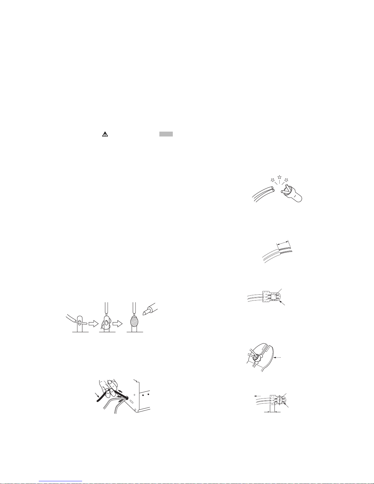
(6) When replacing AC primary side components (transformers,
power cords, noise blocking capacito rs, etc.) wrap ends of
wires securely about the terminals before soldering.
Fig.1-1-1
(7) Observe that wires do not contact heat producing parts
(heatsinks, oxi de metal film resi stors, fu sible re sistors, etc.)
(8) Check that replaced wires do not contact sharp edged or
pointed parts.
(9) When a power cord has been replaced, check that 10-15
kg of force in any direction will not loosen it.
Power cord
cathode ray tubes and other parts with only the specified
parts. Under no circumsta nces atte mpt to m odify these circuits.Unauthorized modification can increase the high voltage value and cause X-ray emission from the cathode ray
tube.
(12) Crimp type wire connector In such cases as when replac-
ing the power transformer in sets where the connections
between the power cord and power trans former primary
lead wires are performed using crimp type connectors, if
replacing the connec tors is unavoidabl e, in order to p revent
safety hazards, perform carefully and precisely according
to the following steps.
• Connector part number :E03830-001
• Required tool : Connector crimping tool of the proper
type which will not damage insula ted part s.
• Replacement procedure
a) Remove the ol d conn ector b y cutting t he wi res at a
point close to the connector.Important : Do not reuse a connector (discard it).
cut close to connector
Fig.1-1-3
b) Strip about 15 mm of the in sulat ion fr om the ends
of the wires. If the wires are stranded, twist the
strands to avoid frayed conductors.
15 mm
Fig.1-1-4
c) Align the lengths of the wires to be connected. In-
sert the wires fully into the connector.
Metal sleeve
Connector
Fig.1-1-5
d) As shown in Fig.1-1-6, use the crimping tool to
crimp the me tal sleeve at t he center posit ion. Be
sure to crimp fully to the complete closure of the
tool.
1.25
2.0
5.5
Crimping tool
Fig.1-1-6
e) Check the four points noted in Fig.1-1-7.
Not easily pulled free
Crimped at approx. cente
of metal sleeve
Fig.1-1-2
(10) Also check areas surrounding repaired locations.
(11) Products us ing cathod e ray tubes (CRTs) In regard to such
products, the cathode ray tubes themselves, the high voltage circuits, and related circuits are specified for compliance with recognized codes pertaining to X-ray emission.
Consequently, when servicing these products, replace the
Conductors extended
Wire insulation recessed
more than 4 mm
Fig.1-1-7
(13) Battery replacement caution notice.
CAUTION RISK OF EXPLOSION IF BATTERY IS REPLACED BY AN INCORRECTIVE TYPE.
DISPOSE OF USED BATTERIES ACCORDING TO THE
INSTRUCTIONS.
(No.HD017<Rev.001>)1-3
Page 4
1.1.2 Safety Check after Servicing
Examine the area surrounding the repaired location for damage
or deterioration. Observe th at screws, parts and wires have been
returned to original positions, Afterwards, perform the following
tests and confirm the specified values in order to verify compliance with safety standards.
(1) Insulation res is tanc e test
Confirm the sp ecified insul ation resistance or greater between power cord plug prongs and externally exposed
parts of the set (RF term inals, antenna termi nals, video and
audio input and output terminals, microphone jacks, earphone jacks, etc.).See table 1 below.
(2) Dielectric strength test
Confirm specified dielectric strength or greater between
power cord plug prongs and exposed accessible parts of
the set (RF terminals, antenna terminals, video and audio
input and output terminals, microphone jacks, earphone
jacks, etc.). See Fig.1-1-11 below.
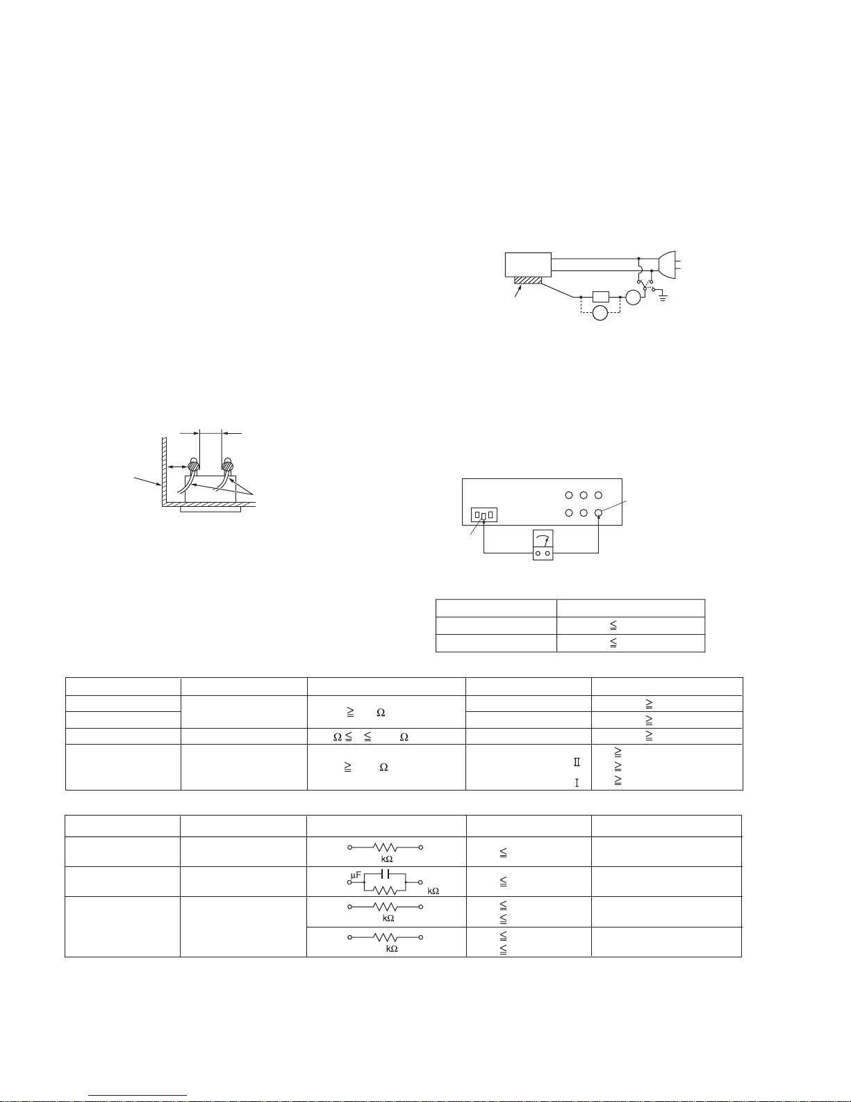
(3) Clearance distance
When replacing primary circuit components, confirm specified clearance distance (d), (d') between soldered terminals, and between terminals and surrounding metallic
parts. See Fig.1-1-11 below.
d
Chassis
d'
Power cord
primary wire
Fig.1-1-8
(4) Leakage current test
Confirm specified or lower leakage current between earth
ground/power cord plug prongs and externally exposed accessible parts (RF t erminals, antenna terminals, vi deo and
audio input and output terminals, microphone jacks, earphone jacks, etc.).
Measuring Method : (Power ON) Insert load Z between
earth ground/power cord plug prongs and externally exposed accessible parts. Use an AC voltmeter to measure
across both terminals of load Z. See Fig.1-1-9 and following Fig.1-1-12.
ab
Externally
exposed
accessible part
Z
V
c
A
Fig.1-1-9
(5) Grounding (Clas s 1 mode l only )
Confirm specified or lower grounding impedance between
earth pin in AC inlet and externally exposed accessible
parts (Video in, Video out, Audio in, Audio out or Fixing
screw etc.).Measuring Metho d:
Connect milli ohm meter between earth pin in AC inlet and
exposed accessible parts. See Fig.1-1-10 and grounding
specifications.
AC inlet
Earth pin
Exposed accessible part
MIlli ohm meter
Grounding Specifications
Region
USA & Canada
Europe & Australia
Grounding Impedance (Z
Z 0.1 ohm
Z 0.5 ohm
)
Fig.1-1-10
AC Line Voltage
100 V
100 to 240 V
110 to 130 V
110 to 130 V
200 to 240 V
Region
Japan
USA & Canada
Europe & Australia
Insulation Resistance (R
R 1 M /500 V DC
1 M R 12 M /500 V DC
R 10 M /500 V DC
)
Dielectric Strength
AC 1 kV 1 minute
AC 1.5 kV 1 minute
AC 1 kV 1 minute
AC 3 kV 1 minute
AC 1.5 kV 1 minute
(
Class
(
Class
Clearance Distance (d), (d'
d, d' 3 mm
d, d' 4 mm
d, d' 3.2 mm
d 4 mm
)
d' 8 mm (Power cord
d' 6 mm (Primary wire
)
Fig.1-1-11
AC Line Voltage
100 V
110 to 130 V
110 to 130 V
220 to 240 V
Region
Japan
USA & Canada
Europe & Australia
Load Z Leakage Current (i)
1
0.15
1.5
2
50
i 1 mA rms
i 0.5 mA rms
i 0.7 mA peak
i 2 mA dc
i 0.7 mA peak
i 2 mA dc
a, b, c
Exposed accessible parts
Exposed accessible parts
Antenna earth terminals
Other terminals
Fig.1-1-12
NOTE :
These tables are unofficial and for reference only. Be sure to confirm the precise values for your particular country and locality.
)
)
)
1-4 (No.HD017<Rev.001>)
Page 5

SECTION 2
SPECIFIC SERVICE INSTRUCTIONS
2.1 MODEL NAME
Model name of printers
XID8600-DS : Dual Side Model
Basic Struct ure
Model Name Convey Unit
XID8600-DS Dual Side
2.2 Model name of built in option units. (Sell separately)
Product name Description Remarks Appended goods
CF-7BR Bend Remedy Unit Remedy the bend of card after retransfer • Pressurized spring
ASSY
•Fixed screw
• Model label
CF-7MGS MG Encoding Unit (ISO) In accordance with ISO7810, 7811/2 MG stripe card
Only for dual side model (built in flip unit)
CF-7CRW Standard Contact IC R/W In accordance with ISO7816 IC card PC/SC, USB connect R/W
When it is installed to the printer, USB or Ethernet is selectable
CF-7CCS ISO Contact IC Case In accordance with ISO7816 IC card Coupled with the ISO MG
encoding unit.
• Connection wire
•Fixed screw
• Model label
• IC contact cable
• USB Cable
•Fixed screw
• Model label
• Option bracket
• GND wire
•Drive board
• Contact label
•Fixed screw
• Model label
2.3 Life time of each p arts
2.3.1 About thermal head
120,000 passes
(Approximately equivalent to 30,000 prints by using 4 colors, YMCK ink ribbon)
The life time of th ermal head is de fined a s the time period when th e heat ing elem ent of the the rmal h ea d is br oken caus ed by wearing
off the surface protective material.
2.3.2 Life time
• Durable parts
1) Heater : 2,000 Hours
2) Thermal Head : 120,000 passes
3) Motor (DC motor ) : 100,000 panels
4) Heat Roller : 100,000 pan els
5) Belt : 100,000 panels
• Consumable parts
Life time to exchange is estimated based on enforcing daily maintenance.
1) Fan Filter : about 1 year
2) Cleaning Roller : about 1 year
• Life time for mechanism
100,000 cards printing for dual side printing with standard maintenance
• MTBF exclude life time parts is more than 12,000 hours
Life time to exchange
Life time to exchange
(No.HD017<Rev.001>)1-5
Page 6
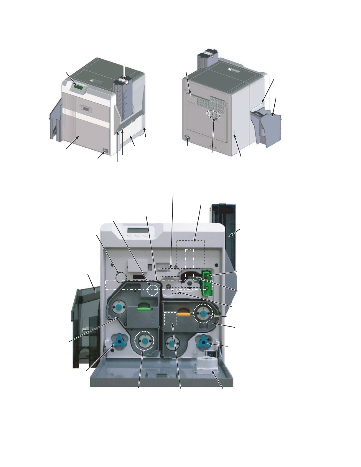
2.4 Name and functions of parts
2.4.1 Exterior
Display Panel
Printer door
Power Switch
2.4.2 Internal mechanism
Retransfer heating roller
Bend Remedy
Heat Roller
Card Hopper
NG Card Exit
Preliminary screw hole
Space for input
out put connectors
Security Slot
Cooling Fan
Contactless IC Encoder install space
Card Convey
Section
AC Inlet
Host Interface
Mag Encoder Unit
Card Exit
Card stacker
Communication Port for Laminator
Card hopper
Card stacker
Re-Transfer
Film Cassette
JOG Dial
Retransfer Film
Thermal head
Cleaning Roller
Card Convey Unit for
Single Sided or Dual Sided
IC Contact
Ink Ribbon
Ink Cassette
JOG Dial
RF-ID Antenna
1-6 (No.HD017<Rev.001>)
Page 7
2.5 ATTACHING THE SEPARATELY SOLD PARTS
r
2.5.1 Preparation
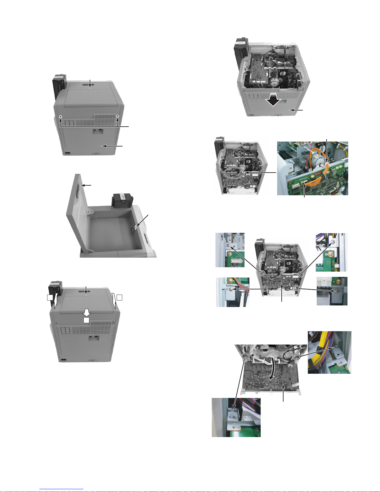
Before connecting the sep arately sol d parts, remove th e top c over unit and the rear cover to pull open the MAIN Board.
(1) Remove the tw o s crews a ttac hi ng f rom the rear side of the
main unit.
Top cover unit
(4) Remove the rear cover by pulling it open to the rear side.
Rear cove
Screw:
QYSDSP4012NA x 2
Rear cover
(2) Open the case cover,then remove the one screw.
Case cover
Screw
(3) Remove th e top cover unit by sliding it to the direction of the
arrow.
Top cover unit
22
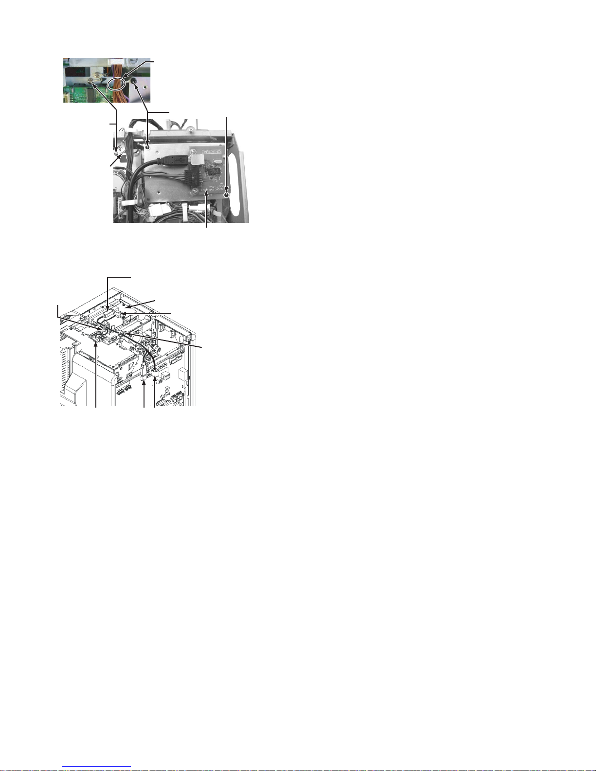
(5) Disconnect the wire connected to the MAIN Board.
Release the wires from the wire clamp.
Disconnect the connector from the turn unit.
(Only the models with turn unit)
(6) Remove the four screws attaching the brackets that fix the
MAIN Board.
Screw : QYSDST3006 x 4
MAIN Board
1
Slide the top cover unit
to the rear side about
10 mm, and then pull it up.
(7) Pull open the MAIN Board, and hook the two brackets at
the bottom of the MAIN Board to the f rame of the main unit.
Main board
• Be careful not to catch wires in between.
(No.HD017<Rev.001>)1-7
Page 8
2.5.2 Attaching the reform H unit
r
A
Note:
After mounting the reform H unit, be su re to ch eck th e relevant item referring to "2.6 Check details after mounting
separately sold parts".
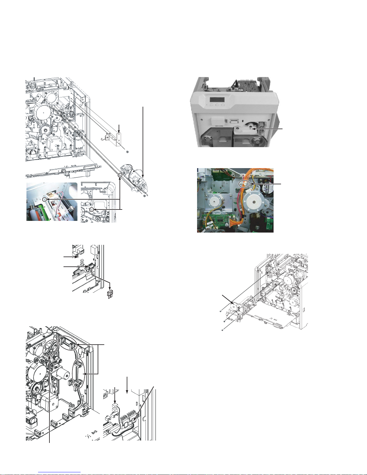
(1) Insert the reform H unit, and fix it with a screw.
(2) Fix the bracket with an attaching screw.
Reform H unit
* When attaching the reform H unit,
be careful not to damage the heat
roller with the bracket.
Bracket
2.5.3 Attaching the IC contact unit
Note:
After mounting the IC contact unit, be sure to check the
relevant item referring to "2.6 Check details after mounting separately sold parts".
(1) Remove the screw attaching the turn unit from the front
side of the main unit.
Screw :
QYSDST3006NA
Screw :
QYSDST3006NA
Screw :
QYSDST3006NA
Insert the tip of the
shaft into the front
plate.
(3) Remove the dummy connector connected to the CN3 on
the MAIN Board. (Only when attaching the reform H unit)
MAIN
Board
CN3
Dummy
connecto
(4) Guide the wires from the reform H unit through the wire
clamps as shown in the drawing, and then connect the
wires to the MAIN Board.
(2) Remove the wires , which come fro m the turn unit, fro m the
wire clamp.
Wire clamp
(3) Remove the three screws attaching the turn unit, and then
pull out the turn unit. (Only the models with turn unit)
Turn unit
Screw :
QYSDST3006NA x 3
Wire clamp
MAIN Board
CN2
s the reform H unit moves up and down during operation,
be sure to allow about 1 to 2 cm wire slack.
1-8 (No.HD017<Rev.001>)
CN3
Page 9
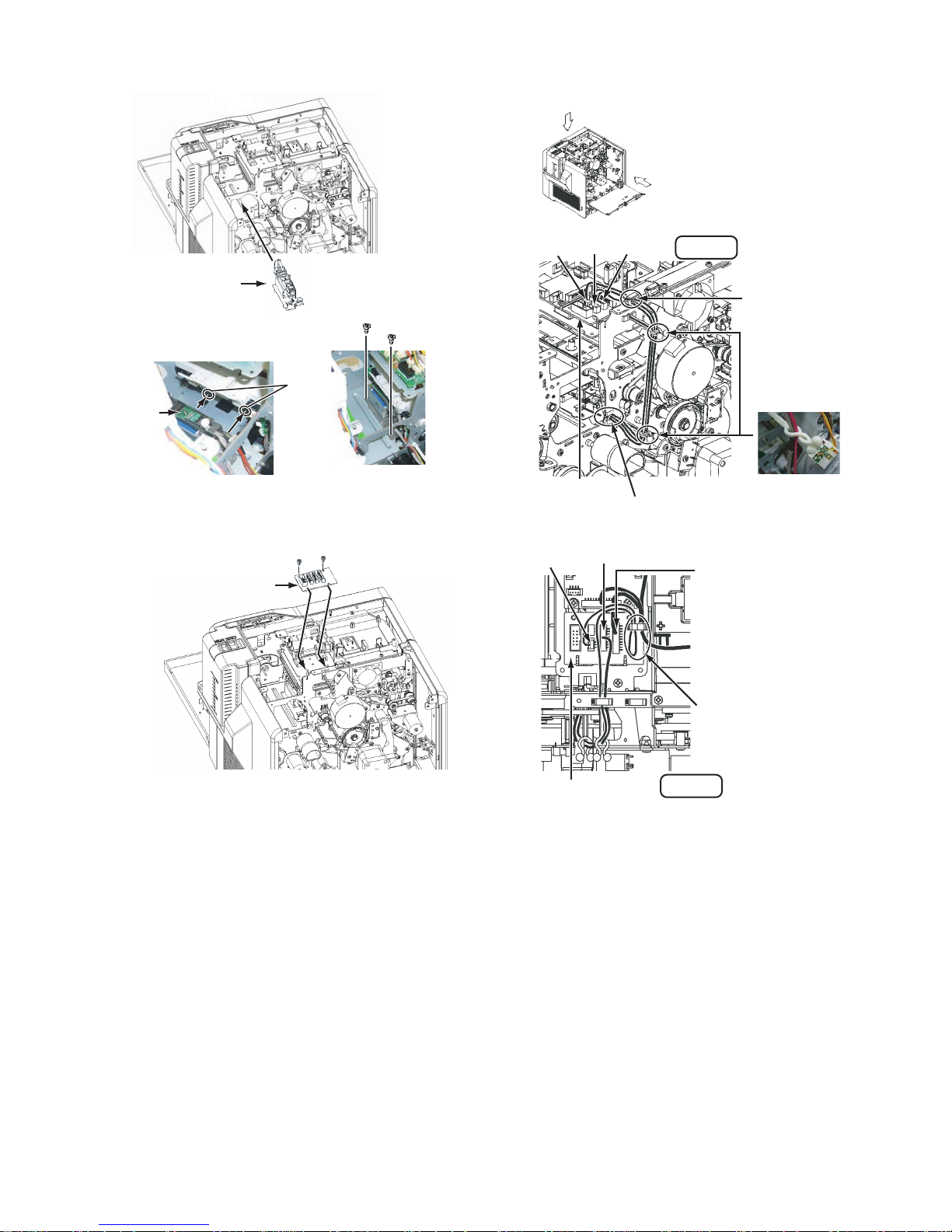
(4) Mount the IC contact unit.
(6) Connect the wire from the IC contact unit following the
drawing below.
B
A
IC Contact unit
Screw :
QYSDST2604NA x 2
Slide the IC contact unit into the
hook of the bracket on the main unit.
Hook
IC Contact
unit
Align the screw holes, make sure that
the IC contact unit does not move, and
then fix the IC contact unit with the screws.
(5) Attach the IC CONTACTIFC Board.
Screw : QYSDST3006NA x 2
IC CONTACTIFC Board
Insert the IC CONTACTIFC
Board into the bracket
on the main unit.
CN4 CN1 CN3
IC CONTACTIFC
Board
Run the wires from the IC contact
unit through this wire clamp.
CN4
CN3
View A
Run the wires through
this wire clamp.
Fix the wires with the two
wire clamps. (Tighten the
wire clampsas shown in the
picture below.)
Be careful to prevent wires from
touching nearby rotating objects
such as belts/gears.
CN2
Connect the free PH10-pin
connector of the jump wire.
Jump wire
IC CONTACTIFC Board
Fold back, and then run the
excess of the wire (red),
connected to the CN4, through
the wire clamp as shown in the
drawing.
View B
(No.HD017<Rev.001>)1-9
Page 10
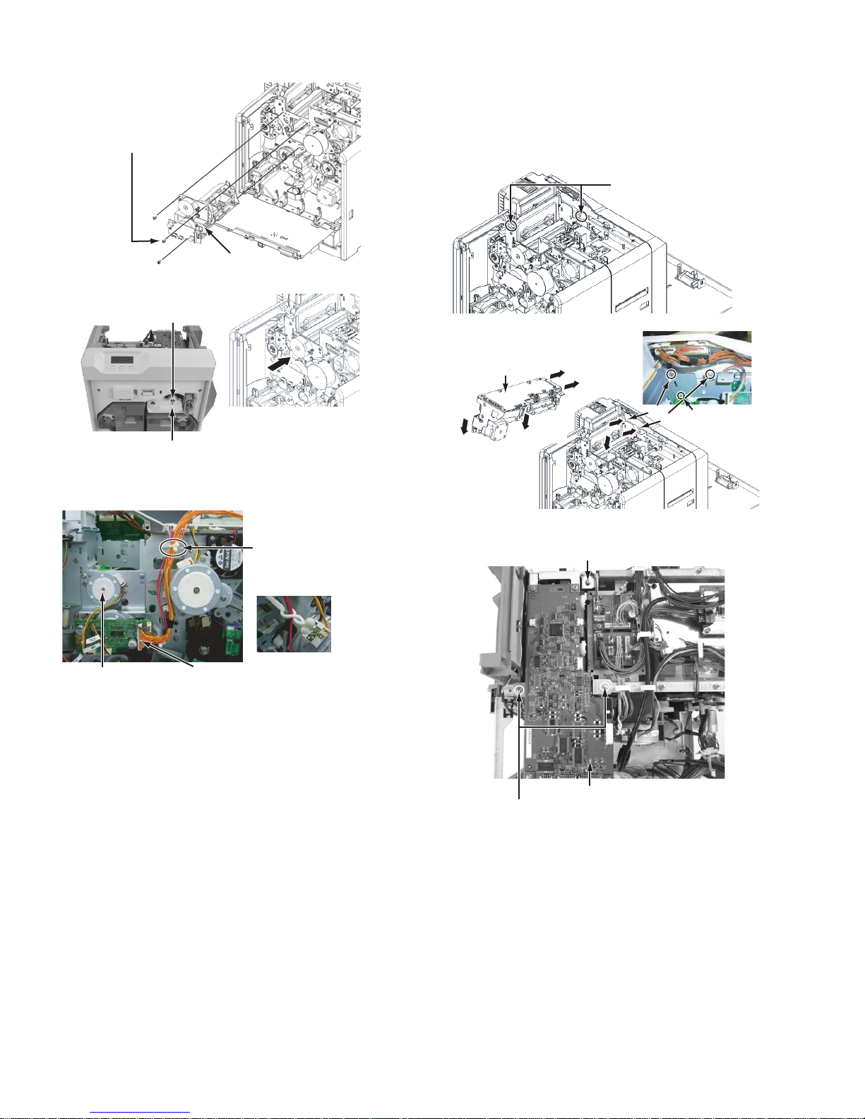
(7) Reattach the turn unit.
A
(c)
fter attaching this screw, attach
another two screws.
Screw : QYSDST3006NA x 3
Turn unit
2.5.4 Attaching the MG unit
Note:
After mounting the MG unit, be sure to check the relevant
item referring to "2.6 Check details after mounting separately sold parts".
(1) Mount the MG unit.
Make sure that the wires do not
run over the brackets.
If the wires run over the brackets,
release the wires.
Bearing fitting hole
Make sure that the turn unit bearing
securely fits the hole on the main unit,
and the screw holes align.
Screw : QYSDST3006NA
Push the turn unit from the rear side to
attach the screw.
(8) Connect the wires from the turn unit following the picture
below.
Wire clamp
Be careful to prevent wires from
touching nearby rotating objects
such as belts/gears.
(Tighten the wire clamp
as shown in the picture
above.)
Turn unit
CN1
Align the front end of the
MG unit to the grooves
(a) and (b) of the front
MG Unit
While aligning the
grooves of the MG unit
bracket and the main unit
bracket, lower the back
end of the MG unit.
bracket.
(c)
(a)
(b)
(a)
(c)
(c)
(2) Fix the MG unit with the three screws.
Screw : QYSDST3006NA
Attention of there is
(b)
groove also under (a).
1-10 (No.HD017<Rev.001>)
MG unit
Screw : QYSDST3006NA x 2
Page 11

(3) Close back the MAIN Board to its original position, and fix
r
MAIN Board
the MAIN Board with the four screws.
Securely hook the two brackets, fixing the
MAIN Board, to the frame of the main unit.
(4) Connect the wires from the MG unit an d the turn unit follow-
ing the drawing below.
Connect the MG unit and the board bracket, and fix them with screws.
Wire : QUB030-05HMHM-E
Screw : QYSDST3006NA x 2
Wire from the turn unit CN1
View A
MAIN Board
Coaxial connector
Make sure that the coaxial
connector is not loose.
Allow about 5 mm slack to
enable the cable to move.
A
B
The cam gear and the wire should be parted.
MG UNIT
Run the wires from the turn
unit and the MG unit togethe
through this wire clamp, and
fix them.
CN19
CN15
MAIN Board
MG Unit
MG unit accessories
Wire from the
turn unit CN1
Wire clamp
MAIN Board
MAIN Board
CN19CN15
2.5.5 Attaching the IC R/W unit
Note:
After mounting the IC R/W unit, be sure to check the relevant item referring to "2.6 Check details after mounting
separately sold parts".
(1) Attach the IC R/W unit to the plate.
QYSPSPH3006NA x 3
Organize the head wire so that it does not
touch the rotating parts such as belts/gears,
and then fix the head wire with the wire clamp.
Make sure that the wires do not touch the encoder.
View B
Opened MAIN Board
IC R/W Unit
QZW0326-002 x 3
(No.HD017<Rev.001>)1-11
Page 12
(2) Mount the IC R/W unit.
Run the earth wire under
the wires from the FRONT Board.
Screw :
Screw :
QYSDST3006NA
Wire :
QUB340-07DMDM-E
QYSDSF3008NA x 2
IC R/W Unit
(3) Connect th e wires f rom the IC R/W un it foll owin g the dra w-
ing below.
Connect the supplied USB cable
and the connector J1 on the MAIN Board.
Wire clamp
IC R/W Unit
Connect the supplied wire (10-pin)
to the connector CN5 on the
IC CONTACTIFC Board.
Wire clamp
CN5 J1
J3
For direct connectio n of the IC R/ W unit and a PC, conn ect
to J3, not to J1.
Note that the IC R/W unit c annot be recogn ized o n the sta tus monitor in the J3 connection.
2.5.6 Attaching the top cover and the rear cover
(1) Attach the to p cover a nd the rear c over in th e reverse r pro-
cedure of disassembly.
1-12 (No.HD017<Rev.001>)
Page 13

2.6 Check details after mounting separately sold parts
Item Check details Required tools
1 Reform H unit The warpage of the printed card should be within the specs (1.5
mm).
2 IC Contact unit Check the IC contact position mark using a blank card and a
contact label.
• Service mode > Offline Test > Test the IC (Contact).
• If the position is out of sp ecs, Ma inte nance > Off setConta ct to
adjust the positi on. (See 2.6.1 IC contac t position adjustmen t)
The card written with an a pplic ation s hould b e read by the reader.
(Check in the USB and Ethernet connections)
3 MG Unit Service mode > Offline Test > test the MG.
• The test should be finished normally.
The card written with an a pplic ation s hould b e read by the reader.
• There is no adjustm ent for an MG un it after mounti ng because
MG units are shipp ed after being position adjust ed. C hec k for
normal operation only.
4 Running after mounting the
separately sold parts
Test for normal printing on about 10 cards
• Service mode > Offline Test > print
(For all separately sold parts)
Item Item Conditions & specs Test point
5 Safety test (for
all separately
sold parts)
Withstand
voltage test
Insulation resistance test
Grounding
continuity test
Timer Leak current Test voltage (With the POWER SW: ON)
2 to 3 sec. 30mA AC1600±50V
Test voltage Insulation resistance value
DC 500V 100MΩ and over
Timer Test current Spec value (With the POWER SW: ON)
3 to 4 sec. AC25A 0.1Ω or under
(Without power cord)
Blank card
Blank card, Contact label
Contact IC card
Contact IC reader
MG card
MG reader
Evaluation card
GND C on the AC inlet in the
drawing below
|
Bipolar B on the po wer cor d in
the drawing below
Screw A on the top left of the
rear panel in the drawing belo w
|
GND C on the AC inlet in the
drawing below
A
C
B
(No.HD017<Rev.001>)1-13
Page 14
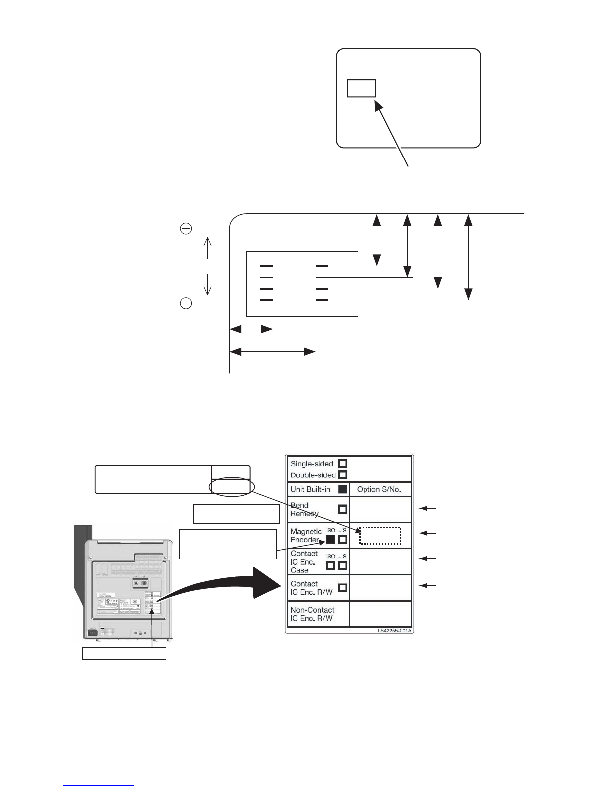
2.6.1 IC contact position adjustment
Apply a contact label (part number: KXL46372-001) on the IC
chip of a contact IC card.
Select the IC contact test from “off line test” in the service mode
to perform the test.
After the test, measure the IC contact position mark on the contact label using a vernier caliper to check if the position stays
within the specs.
If the position does not stay wi thin the spec s, correct the po sition
in the “OffsetContact” mode in the service mode.
When the position is corrected, turn off the power and turn it on
again before testing the IC contact.
(Specs)
direction
IC contact
position specs
direction
a
b
Contact label
(part number:KXL46372-001)
c
d e f
a : 10.25 ~ 12.25 mm
b : 17.87 ~ 19.87 mm
c : 19.23 ~ 20.93 mm
d : 21.77 ~ 23.47 mm
e : 24.31 ~ 26.01 mm
f : 26.85 ~ 28.55 mm
2.6.2 Optional installed label
When installing opt ional unit after ship ping from JVC, mark c orresponding col umn of option built- in label and stick model label attac hed
with optional unit to secure traceability.
Model label attached with option
Optional installed label
(ex. CF-7MGS)
NOTE)This option must be installed, following procedures
in the Service Manual , by a trained and skilled installer in
a facility. Stick the small label on the printer rear after
installation of this option unit.
CF-7MGS
Magnetic Encoder (ISO)
Rear side
Mark corresponding
CF-7MGS
xxxxxxxx
CF-7MGS
xxxxxxxx
Stick model label
For CF-7BR
For CF-7MGS
column
For CF-7CCS
For CF-7CRW
Installed option label
1-14 (No.HD017<Rev.001>)
Page 15
SECTION 3
DISASSEMBLY
Before disassembly, be sure to turn OFF the power and unplug
the power cord.
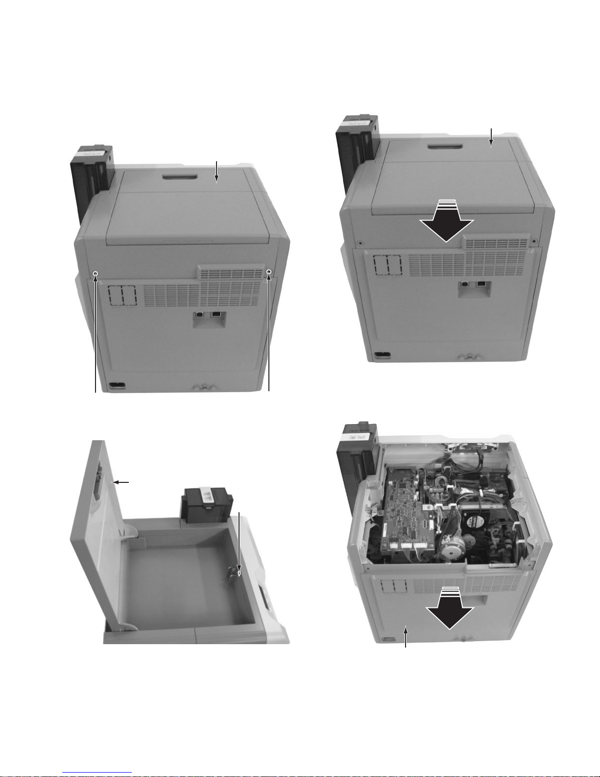
3.1 Removing the covers (See figure 1 to figure 5)
(1) Remove the two screws A attaching the top cover unit.
Top cover unit
(3) Slide the top cover unit to the rear side, then remove the
top cover unit.
Top cover unit
A
Fig.1
(2) Open the case cover, then remove the one screw B.
Case cover
B
Fig.2
A
Fig.3
(4) Pull the rear cover unit open to the rear side, then remove
the rear c over unit.
Rear cover unit
Fig.4
(No.HD017<Rev.001>)1-15
Page 16

(5) Remove the two screws C attaching the side cover U-R
and side cover U-L, then remove the side cover U-R and
side cover U-L.
(2) Remove the two screws D attaching the cover, then re-
move the cover.
C
Side cover U-R
Side cover U-L
C
Fig.5
3.2 Removing the front panel unit (See figure 6 to figure
13)
(1) Remove the Media F CA un it, the Ink F CA u nit, and the CL
Roller unit.
CL Roller unit
D
Cover
Head unit
Fig.7
(3) Remove the four screws E attaching the front panel unit.
• Be careful not to break the cable.
E
Front panel unit
E
Media F CA unit
Ink F CA unit
Fig.6
1-16 (No.HD017<Rev.001>)
E
Cable
E
Fig.8
Page 17
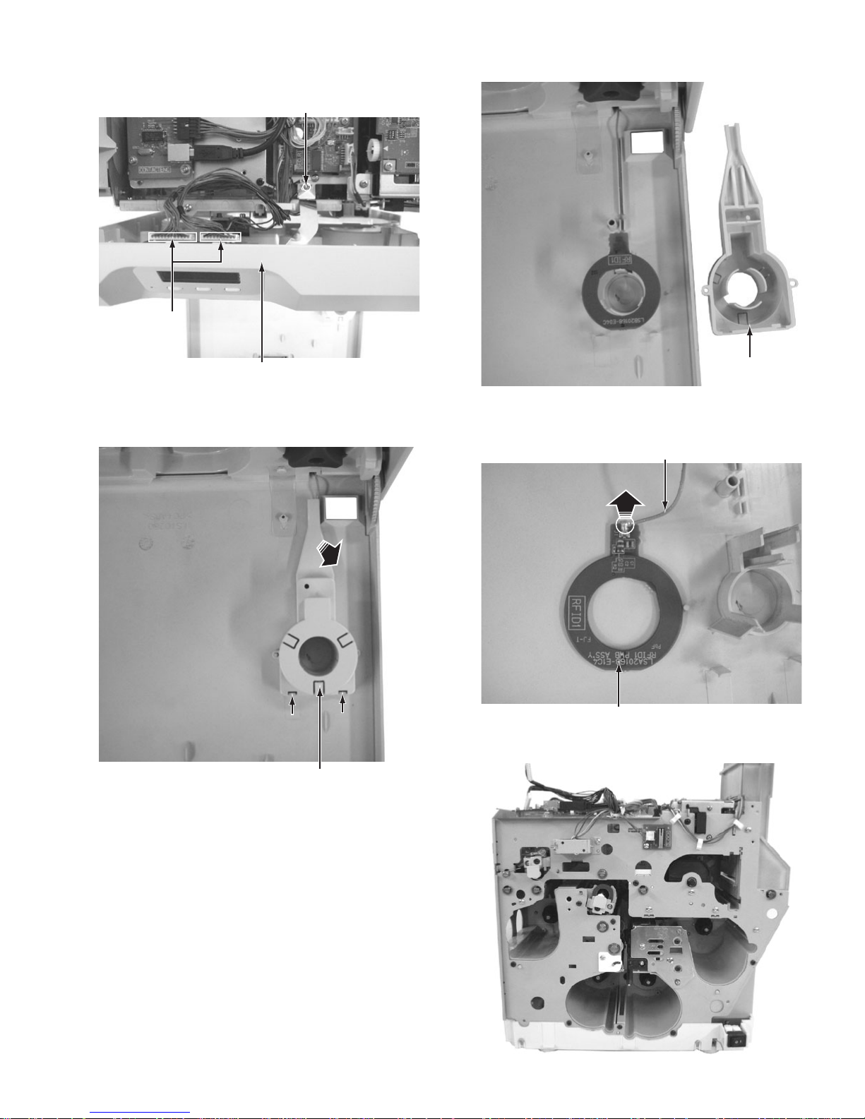
(4) Disconne ct the two c ables fro m the con nectors o n the front
Tab
Tab
board, then remove the one screw F.
F
Connectors
(6) Front panel unit with the co ver removed.
Front panel unit
Fig.9
(5) Press the two tabs, pull up the cover at the point marked
with an arrow, and then remove the cover.
Tab
Tab Tab
Tab
Cover
Fig.11
(7) Disconnecting the cable from the RFID1 board detaches
the front panel unit from the main unit.
Cable
RFID1 board
Fig.12
(8) Main unit with the front panel unit removed.
Fig.10
Cover
Fig.13
(No.HD017<Rev.001>)1-17
Page 18

3.3 Removing the major boards and major units (See figure 14 to figure 34)
(1) Disconnect the four cables from the connectors on the
main board.
(2) Remove the four screws G attaching the main board.
(4) Hanging the left and right brackets on the mai n board to the
hooks on the chassis prev ents the main board fr om falling.
Hook
G
G
Main board
Connectors
Fig.14
(3) Pull the main board open to the rear side.
G
Fig.16
Hook
G
Main board
Fig.15
Fig.17
(5) Remove the three screws H attaching the MG encoding
unit, then remove the unit.
H
MG encoding unit
H
Fig.18
1-18 (No.HD017<Rev.001>)
Page 19

(6) Removed MG encoding unit.
Fig.19
(7) The KEY LOCK UNIT consists of a SECURITY PWB ASSY
and two solenoids.
SECURITY PWB ASSYSolenoid
(9) Remove the four screws K to release the SECURITY PWB
ASSY and the solenoid on the front side.
K
K
Solenoid
SECURITY PWB ASSY
Fig.22
(10) Removed KEY LOCK UNIT SET. (LS31237-201A)
Solenoid
Fig.20
(8) Remove the one screw J to release the solenoid on the
card stocker side.
J
Solenoid
Fig.21
Fig.23
(11) Remove the two screws L, then remove the bra cket with IC
R/W UNIT.
L
IC R/W UNIT
(CF-7CRW)
Fig.24
(No.HD017<Rev.001>)1-19
L
Page 20

(12) Removed IC R/W UNIT.
This bracket is an accessory of
the IC contact unit.
(14) Remove the two screws N attaching the cover, then re-
move the cover.
N
Fig.25
(13) Remove th e on e sc rew M attaching the bracket with CON-
TACTIFC board, then slide the CONTACTIFC board forward to remove.
CONTACTIFC board
M
Fig.26
Cover
N
Fig.28
(15) Before removing the IC contact unit, the turn unit needs to
be removed first.
IC contact unit
Fig.29
• To attach the CONTACTIFC board, insert the part a into
the slit on the front side.
Part a
Fig.27
1-20 (No.HD017<Rev.001>)
Page 21

(16) Remove the four screws P attaching the turn unit from the
front side and the rear side.
Turn unit
(18) Remove the two screws Q attaching the IC contact unit,
then remove the unit.
IC contact unit
P
(17) Removed turn unit.
Fig.30
Turn unit
Fig.31
P
Q
Fig.33
P
(19) Removed IC contact unit.
ISO: CF-7CCS
P
This bracket is an accessory of
the card printer unit.
Fig.34
Fig.32
(No.HD017<Rev.001>)1-21
Page 22

3.4 Replacing the head unit (See figure 35 and figure 36)
(1) Remove the one screw R attaching the head unit.
R
3.5 Removing the reform H unit (See figure 37 and figure
38)
(1) Remove the one scr ew S attaching the reform H unit, then
pull out the reform H unit.
(2) To replace the heater only, remove the one screw T.
Head unit
Fig.35
(2) Pull out the head unit paying attention to the cable, then
disconnect the two connectors.
Connectors
Note:
* Do not cut the cable lock. This cable lock is removable.
* Press to loosen the lock in the direction of the arrow.
The cable lock can be removed.
Fig.36
T
S
Fig.37
(3) Removed reform H unit.
Heater
Fig.38
3.6 Replacing the heater on the heat unit (See figure 39
and figure 40)
(1) Remove the one screw U attaching the cover from the front
side.
1-22 (No.HD017<Rev.001>)
U
Fig.39
Page 23

(2) Pulled out heater.
r
(3) Remove the five screws V attaching the motor base unit,
then remove the motor base unit.
V
Heater
Fig.40
3.7 Removing the motor base unit (See figure 41 to figure
44)
(1) Push two tabs on the PS cover, then remove the PS cov er.
PS cover
Fig.41
(2) Main unit with the PS cover removed
Motor base unitCable for head unit
V
Fig.43
(4) Main unit with the motor base unit removed.
Motor base unit
Power supply unit
Fig.42
When the gear is detached, the position of a triangula
sign and a round sign is matched and installed.
Fig.44
(No.HD017<Rev.001>)1-23
Page 24

SECTION 4
r
ADJUSTMENT
This service manual does not describe ADJUSTMENT.
SECTION 5
TROUBLE SHOOTING
5.1 When an error message is display
When the error occurs, the error code and the e rror code number
are displayed in the operation panel.
Solve the error referring to the following when the error occurs.
XXXXXXXXX XX
Error code Error code numbe
5.1.1 No Card
No Card
• Cards have run out.
Replenish the cards.
• The card hopper is not installed.
Install the card hopper.
Memo:
• The operation panel display appears blinking when the
cards have run out o r when the c ard hop per is not installe d.
• Replenish the cards.
• The card hopper is able to store up to about 100 cards with a
thickness of 0.76 mm.
Cautions:
• Get ready cards that a re designat ed by the authoriz ed dealer.
• If the security lock is on, deactivate it. After work is complete,activate the security lock again.
• Do not touc h the printing su rface of the car d. Touching it
may cause printing e rrors. Pu t on th e sup plied gl oves when
handling the cards.
• To prevent card jams from occurring, limit the number of
cards stored in the card hopper at any time to about 100
pieces regardless of the card thickness.
• When using new card s, set them after m aking sure that th ey
are not adhered to each other due to static.
• Align the cards before setting them in the printer. Otherwise, the card hopper cover may not close properly, and
this may damage the printer.
• Printing th e card on the si de with the magn etic st ripe may
cause printing errors or damage to the card’s functions. If
you want to do so, plea se c on sult our authorized dealers in
advance.
• To set cards with both functions (magnetic stripe and contact IC),follow the procedure for se tting the co ntact IC card.
(1) Set the card hopper knob to [OPEN].
(2) Lift to remove the card hopper cover.
(3) Align the orientation of the cards, and set them in the
printer.
• Magnetic stripe cards
- Set the card with the magnetic stripe facing upward
and toward the printer, or facin g downward and toward
you.
• ISO contact IC cards
- Set the card with the Contact IC terminal facing upward and toward the rear of the printer, or downward
and toward the rear of the printer.
- For single-sided printers, set the cards with the IC terminal facing down and toward the rear of the printer.
(4) Install the card hopper cover, and set the card hopper
knob to [LOCK]
1-24 (No.HD017<Rev.001>)
Page 25

5.1.2 Jam(Hopper) 90
Jam (Hopper) 90
• Card jam near the card hopper and cleaning roller.
Remove the jammed card.
Note:
• Do not apply excessive force on the card hopper. Doing so
may damage it.
• Do not touch the printing surface of the card. Touching it
may cause printing errors. Put on the supplied gloves when
handling the cards.
(1) Detach the card hopper cover, and remove the unused
cards.
• The card is discharged from the NG card outlet.
5.1.2.2 If the card cannot be discharged
(1) Turn off the power.
(2) Open the printer door, and check the position of the
jammed card.
(3) Attach the jog dial to the cleaning roller shaft.
(2) Remove the jammed card with a hand.
(3) Return the unused cards to their original position.
(4) Install the card hopper cover.
5.1.2.1 If the card cannot be removed by hand.
(1) Press [RESET] → to reset the printer.
(4) Turn the cleaning roller shaft in the clockwise direction,
while checking the position of the card.
(5) Remove the card after it is discharged from the card load
slot.
(6) Restore the jog dial to its original position, and close the
printer door.
(7) Turn on the power.
(No.HD017<Rev.001>)1-25
Page 26

5.1.3 Jam(TurnOver) 91
Jam (Turn Over) 91
• Card jam near the card turn over unit.
Remove the jammed card.
(1) Turn off the power.
(2) Remove the card hopper.
(6) Install the cleaning unit.
(7) Attach the jog d ial to the card t urn over un it s haf t, an d set
the card turn over unit to “Home Pos.”
• “Home Pos.” is the position where the slit on the jog dial
points to the righ t and the card turn over unit is h orizontal.
(3) Detach the card load slot cover.
(4) Open the printer door, and remove the cleaning unit.
(8) Restore the jog dial to its original position.
(9) Install the card load slot cover and card hopper, and close
the printer door.
(10) Turn on the power.
Cautions:
• When a Jam(TurnOver) error occurs, the [Jam(TurnOver)]
message will not d isappear after re moving the jam med card
until the card turn over unit is set to “Home Pos.”.
• If the printer door is opened when a Jam(TurnOver) error
occurs, a [Please Adjust Turn Unit Pos!] message will be
displayed. Remove the jammed card, and set the card turn
over unit to “Home Pos.”.
5.1.3.1 If the card cannot be removed
(1) Install the cleaning unit.
(2) Attach the jo g di al to t he c le ani ng roll er s ha ft an d c ard turn
over unit shaft.
(5) Remove t he jammed card i n the card turn o ver unit from the
card load slot.
1-26 (No.HD017<Rev.001>)
Page 27

(3) Set the card turn over unit to “Home Pos.”
• “Home Pos.” is the position where the slit on the jog dial
points to the righ t and the card t urn over unit is horizontal.
• If the card protrudes fr om the card turn over u nit, turn the
cleaning roller shaft to move the card into the unit.
• Turning the card turn over un it moves the c ard inside the
unit outward. Turn the card turn over unit while turning
the cleaning roller s haft so that th e card is reta ined inside
the card turn over unit, and set to “Home Pos.”.
5.1.4 Jam(MG) 92
Jam (MG) 92
• Card jam in the magnetic encoder unit.
Remove the jammed card.
(1) Press [RESET] → to reset the printer.
• The card is discharged from the NG card outlet.
Cautions:
• Do not turn the ca r d t urn ov er un it fo rc i bl y if the r e i s a ca rd
inside the unit.
Doing so may jam the card and damage the printer.
(4) Turn the cleaning roller shaft in the clockwise direction.
(5) Remove the card after it is discharged from the card load
slot.
Go to step 8 of 5.1.3.
5.1.5 Jam(Transfer) 93
Jam (Transfer) 93
• Card jam in the card feed roller.
Remove the jammed card.
(1) Press [RESET] → to reset the printer.
(No.HD017<Rev.001>)1-27
Page 28

• The card is discharged from the NG card outlet.
5.1.5.1 If the card cannot be discharged
(1) Turn off the power, and detach the card hopper.
(2) Open the printer door, and check the position of the
jammed card.
(3) Attach the jo g dial to the car d feed roller sh aft and clean ing
roller shaft.
5.1.6 Jam(Discharge) 94
Jam (Discharge) 94
• Card jam near the card outlet.
Remove the jammed card.
(1) Press [RESET] → to reset the printer.
• The card is discharged from the card outlet.
.
(4) Turn the card feed roller shaft and cleaning roller shaft in
the clockwise direction, while checking the position of the
card.
• Remove the card a fter it is discha rged from t he card l oad
slot.
(For single-sided printers, the card is discharged from
the NG card outlet.)
(5) Restore the jog dial to its original position.
(6) Install the card hopper, and close the printer door.
(7) Turn on the power.
5.1.6.1 If the card cannot be discharged
(1) Turn off the power, and open the printer door.
(2) Pull out the retransfe r film c assette, an d chec k the po sition
of the card.
(3) Attach the jog dial to the card feed roller shaft.
1-28 (No.HD017<Rev.001>)
Page 29

(4) Turn the card feed roller shaft in the anti-clockwise direc-
tion, while checking the position of the card.
• The card is discharged from the card outlet.
(5) Restore the jog dial to its original position, and install the re-
transfer film cassette.
(6) Close the printer door, and turn on the power.
5.1.7 Jam(Retran.) 95
Jam(Retran.) 95
• Card jam near the retransfer heating roller.
Remove the jammed card.
(1) Open the printer door.
• A [Please Remove Jam Card!] or [Please Close Door]
message appears.
(2) Pull out the retransfer film cassette.
(5) Press [RESET] .
• A [Jam Card Removed?] message appears.
(6) Press [Yes] .
Cautions:
• Initializing the printer without first removing the card will
cause the printer to m alfunction. Be sure to remove the card
then press [Yes].
• An [Initializing..] message appears, and initialization of
the printer starts.
Cautions:
• The card may be adhered to the retrans fer film. Pu ll out the
retransfer film while taking care not to jam it.
• If a [Please Close Door] me ssage is di splayed , the retransfer film is stuck and the retransfer film cassette cannot be
removed.
In this case, close the print er door before pullin g out the retransfer film cassette.
(3) Remove the jammed card.
There is an explanation in each sympt om.
• If the card is adhered to the retransfer film.
• If the card is inside the printer unit.
• If the card is caught in the card feed roller to the right of
the retransfer heating roller.
• If the card is caught in the card fee d roller to the left of the
retransfer heating roller.
(4) Install the retransfer film cassette, and close the printer
door.
5.1.7.1 If the card is adhered to the retransfer film
• Remove the jammed card with a hand.
Cautions:
• The card may be very h ot. Be carefu l not to burn yo ur fingers when removing the card.
Go to step 4 of 5.1.7.
(No.HD017<Rev.001>)1-29
Page 30

5.1.7.2 If the card is inside the printer unit
• If the card is n ot drawn in to the card feed roller a nd is left i nside
the printer, use the tweezers (supplied) to remove the card.
(1) Turn off the power.
(2) Check the positi on of the card that is left inside the printer.
(3) Pick up the card us ing the tip of th e card Pickup . (supplied )
• Be careful not to drop the card inside the printer.
(4) Pull out the card slowly.
5.1.7.3 If the card is caught in the card feed roller to the
right of the retransfer heating roller
(1) Turn off the power, and detach the card hopper.
(2) Check the position of the card.
(3) Attach the jo g dial to the car d feed roll er shaft and cl eaning
roller shaft.
Cautions:
• The card may be very hot. Be careful not to burn your fingers when removing the card.
Memo:
Example of how to pick up the card
• Pick up the card by following the diagram above.
(5) Install the retransfer film cassette, and close the printer
door.
(4) Turn the card feed roller shaft and cleaning roller shaft in
the clockwise direction, while checking the position of the
card.
• Remove the card a fter it is discha rged from t he card l oad
slot.
(For single-sided printers, the card is discharged from
the NG card outlet.)
(5) Restore the jog dial to its original position, and install the
card hopper.
(6) Install the retransfer film cassette, and close the printer
door.
(7) Turn on the power.
Go to step 5 of 5.1.7.
(6) Turn on the power.
Go to step 5 of 5.1.7.
1-30 (No.HD017<Rev.001>)
Page 31

5.1.7.4 If the card is caught in the card feed roller to the
left of the retransfer heating roller
(1) Turn off the power.
(2) Check the position of the card.
(3) Attach the jog dial to the card feed roller shaft.
(4) Turn the card feed roller shaft in the anti-clockwise direc-
tion, while checking the position of the card.
• The card is discharged from the card outlet.
(5) Restore the jog dial to its original position.
(6) Install the retransfer film cassette, and close the printer
door.
(7) Turn on the power.
Go to step 5 of 5.1.7.
5.1.8 Film Search A1
Film Serch A1
• Retransfer film is broken.
Repair the retransfer film.
Cautions:
• If the security lock is on, deactivate it. After work is complete, activate the security lock again.
• Stand the cass ette on a f lat surface as illustrated in the di agram.
Avoid doing so on the floor as dust atta ched to it may ca use
printing errors.
• Do not touch the retransfer face (the side that faces outward
when installed) with your hand . Touching it may cau se printing errors. Put on the suppl ied g loves when handl ing th e retransfer film.
• The cassette i s hea vy wh en the retran sfer fi lm i s loa ded. T o
prevent the cassette from dropping during handling, make
sure to hold it with both hands.
• When installing a used re transfer fil m, align the unused s ide
of the film with the arrow indicated on the label of the cassette. Improper alignment may result in errors, or the print
may turn out light.
• Do not perform any work on the printer door. Do not place
heavy objects or apply load on the printer. Doing so may
damage it.
• During replacement, clean the four bobbin holders on the
printer. If burrs produced by friction with the bobbins are attached to the bobbin hold ers, they m ay fall onto the card, ink
ribbon, or retransfer film, causing printing errors.
(1) Open the printer door.
(2) Press and hold down the cassette button, and remove
the retransfer film cassette. (on the left)
(3) Cut away the broken portion, an d attach the unus ed portion
at the supply sid e to the other end at the take-up s ide usi ng
an adhesive tape, while making sure that the joint surface
is even.
Cautions:
• Do not discard the used retransfer film at the take-up side.
(No.HD017<Rev.001>)1-31
Page 32

(4) Turn the take-u p side using your hand until the brok en por-
tion can no longer be seen.
5.1.9 MG Test Err A8
MG Test Err A8
• A writing error has occurred during magnetic encoder self-diagnosis.
Press [RESET] → to reset the printer.
• Align the film side of the unused portion with the arrow indicated on the label of the cassette.
(5) Remove any slack in the film.
(6) Insert the ca ssette all the way in along the guide rail un til
a “click” sound is heard, followed by closing the printer
door.
(7) Press [RESET] → to reset the printer.
5.1.10 Ink Error B0
Ink Error B0
• An incorrect ink ribbon is installed.
Install a correct ink ribbon.
5.1.11 Ink Search B1
Ink Serch B1
• Ink ribbon is broken.
Repair the ink ribbon.
Cautions:
• If the security lock is on, deactivate it. After work is complete, activate the security lock again.
• Stand the cassette on a flat surface as illustrated in the diagram. Avoid doing so on the floor as dust attached to it
may cause printing errors.
Memo:
• To avoid printi ng errors , it is recommende d that you forward
by one or two images after inst allin g the ink rib bon casse tte
or retransfer film cassette.
• Do not touch the inked s urface (the side that fac es outward
when installed) with your hand. Touching it may cause
printing errors. Put on the supplied gloves when handling
the ink ribbon.
• The cassette is heavy when the ink ribbon is loaded. To
prevent the cassette from dropping during handling, make
sure to hold it with both hands.
• When installing a used ink ribbon, align the yellow side of
the unused ribbon with the arrow indicated on the label of
the cassette. If the posi tion of the yellow side is not properly
aligned, the print may turn out light.
• Do not perform any work on the printer door. Do not place
heavy objects or apply load on the printer. Doing so may
damage it.
• During replacement, clean the four bobbin holders on the
printer. If burrs prod uced by frictio n wi th the b obbin s are a ttached to the bobbin holders, they may fall onto the card,
ink ribbon, or retransfer film, causing printing errors.
(1) Open the printer door.
1-32 (No.HD017<Rev.001>)
Page 33

(2) Press and hold down the cassette button, and remove
the ink rib bon cassette. (on the right)
(3) Cut away the broken portion, an d attach the unus ed portion
at the supply sid e to the other end at the take-up s ide usi ng
an adhesive tape, while making sure that the joint surface
is even.
Cautions:
• Do not discard the used ribbon at the take-up side.
(4) Turn the take-up sid e using your hand unt il the broken por-
tion can no longer be seen.
(7) Press [RESET] → to reset the printer.
Memo:
• To avoid printing errors, it is rec ommended that y ou forward
by one or two image s after ins talling t he ink rib bon ca ssette
or retransfer film cassette.
5.1.12 Door Open D1
Door Open D1
• Align the yellow sid e of the unused po rtion with the arrow
indicated on the label of the cassette.
(5) Remove any slack in the ink ribbon.
(6) Insert the cass ette all the w ay in along the gui de rail until
a “click” sound is heard, followed by closing the printer
door.
• The printer door is open.
Close the printer door, and Press [RESET] → to reset the
printer.
• Cleaning unit is not installed.
Install the cleaning unit, close the printer door, and press
[RESET] → to reset the printer.
Memo:
• The operation pane l display appears blin king when the print er door is open or when the cleaning unit is not installed.
5.1.13 Film Run Out A2
Film Run Out A2
• Retransfer film has run out.
Replace with a new one.
5.1.14 Ink Run Out B2
Ink Run Out B2
• Ink ribbon has run out.
Replace with a new one.
5.1.15 Hardware 44
.
Hard ware 44
• A hardware failure has occurred on the printer.
Turn off and on the power again. If the same problem recurs,
turn off the power and consult our authorized dealers.
(No.HD017<Rev.001>)1-33
Page 34

5.1.16 MG Mechanical AB
5.1.23 TR Thermister F2
MG Mechanical AB
• An error has occurred in the mechanical component of the
magnetic encoder.
Turn off and on the power again. If the same problem recurs,
turn off the power and consult our authorized dealers.
5.1.17 MG Hardware AC
MG Hardware AC
• A hardware failure has occurred on the magnetic encoder.
Turn off and on the power again. If the same problem recurs,
turn off the power and consult our authorized dealers.
5.1.18 Cam Error C1
Cam Error C1
• A heating roller operation error has occurred .
Turn off and on the power again. If the same problem recurs,
turn off the power and consult our authorized dealers.
5.1.19 HR Overheat C2
HR Overheat C2
TR Thermister F2
• The retransfer heating roller thermistor is faulty.
Turn off and on the power again. If the same problem recurs,
turn off the power and consult our authorized dealers.
5.1.24 RR Overheat F3
RR Overheat F3
• The temperature o f the bend remedy heating ro lle r i s too high.
Turn off and on the power again. If the same problem recurs,
turn off the power and consult our authorized dealers.
5.1.25 RR Heater F4
RR Heater F4
• The bend remedy unit is faulty.
Turn off and on the power again. If the same problem recurs,
turn off the power and consult our authorized dealers.
5.1.26 RR Thermister F5
RR Thermister F5
• The temperature of the bend remedy heating roller or retransfer heating roller is too high.
Turn off and on the power again. If the same problem recurs,
turn off the power and consult our authorized dealers.
5.1.20 Hardware D8
Hardware D8
• A hardware error has occurred during initialization.
Turn off and on the power again. If the same problem recurs,
turn off the power and consult our authorized dealers.
5.1.21 TR Overheat F0
TR Overheat F0
• The temperature of the retransfer heating roller is too high.
Turn off and on the power again. If the same problem recurs,
turn off the power and consult our authorized dealers.
5.1.22 TR Heater F1
TR heater F1
• The bend remedy heating roller thermistor is faulty.
Turn off and on the power again. If the same problem recurs,
turn off the power and consult our authorized dealers.
5.1.27 Overcool F6
Overcool F6
• The operating ambient temperature of the printer is too low.
Check the te mp e rat u re. I f th e s am e pro bl e m re cu r s wit hin t h e
range of operating ambient temperatu re, turn off th e power and
consult our authorized dealers.
5.1.28 Head Overheat F8
Head Overheat F8
• The temperature of the thermal head is too high.
Turn off and on the power again. If the same problem recurs,
turn off the power and consult our authorized dealers.
5.1.29 Power Intrpt C3
Power Intrpt C3
• The retransfer heating roller is faulty.
Turn off and on the power again. If the same problem recurs,
turn off the power and consult our authorized dealers.
1-34 (No.HD017<Rev.001>)
• An instantaneous interruption is detected.
Turn off and on the power again. If the same problem recurs,
turn off the power and consult our authorized dealers.
Page 35

5.2 Use of service mode
Besides "User mode" that is for setting this unit depending on the printing media or card used by the user, there is a "Service mode"
for status checking and changing setting of this unit during service. The checking and adjustment of the following items can be performed in service mode:
(1) Fine adjustment of the printing position
(2) Printing of built-in test pattern
(3) Operation checking of various motors and sensors
(4) Information display of printer
(5) Saving of setting data
(6) Setting change of user mode
For user mode, only the items that can be changed in this mode are described.
For details of other items, please refer to the instruction manual.
5.2.1 Entry into service mode
In ready condition, in preheating condition, or in error condition, press the buttons [MENU] and [Center button] simultaneously.
When the button [MENU] is released first, the printer will enter into the following service mode.
>Maintenance> >>Offset Prt Y
[NEXT]
[ENTER]
[EXIT]
>>Offset Prt X
>>Offset Trf X
>>Offset Card X
>>Ink Snsr Lvl
>>Film Snsr Lvl
>>IC ContactType
>>OffsetContact
>>ISO Hico Type
>>JIS Loco Type
>>IC Antenna
>>Vth Gain
>>Ink Eco Mode
>>B.RemedySpeed
[ENTER]
>User Mode>
[NEXT]
[EXIT]
>>Media
>>Print
1 1
[NEXT]
[NEXT]
[NEXT]
[NEXT]
[NEXT]
[NEXT]
[NEXT]
[NEXT]
[NEXT]
[NEXT]
[NEXT]
[NEXT]
[NEXT]
[NEXT]
[NEXT]
Setting of the printing position Y
[-15(Front) ~ -1(Front),0,+1(Back) ~ +15(Back)]
Select with [ ] and save with [ ].
Setting of the printing position X
[-7(Left) ~ -1(Left),0,+1(Right) ~ +7(Right)]
Select with [ ] and save with [ ].
Setting of the retransfer position X
[-14(Left) ~ -1(Left),0,+1(Right) ~ +14(Right)]
Select with [ ] and save with [ ].
Setting of the card stop position X
[-7(Left) ~ -1(Left),0,+1(Right) ~ +7(Right)]
Select with [ ] and save with [ ].
Adjust the threshold level of the Ink-Sensor
[0 ~ 254]
Select with [ ] and save with [ ].
Adjust the threshold level of the Film-Sensor
[0 ~ 254]
Select with [ ] and save with [ ].
Select IC Contact Type
[ISO/JIS]
Select with [ ] and save with [ ].
Setting of the Offset Contact
[-15 ~ -1, 0, 1 ~ +15]
Select with [ ] and save with [ ].
Select ISO Hico Type
[Standard, Super]
Select with [ ] and save with [ ].
Select JIS Loco Type
[Standard, Overlay]
Select with [ ] and save with [ ].
Setting of IC Antenna
[None, Installed]
Select with [ ] and save with [ ].
Vth Gain Adjustment
[0 ~15]
Select with [ ] and save with [ ].
Ink Eco Mode Setting
[On,Off]
Select with [ ] and save with [ ].
Transporting Speed Setting
[Standard,Fast]
Select with [ ] and save with [ ].
[ENTER]
[EXIT]
[ENTER]
[EXIT]
>>>Film Type
[NEXT]
>>>Card Thickness
>>>YMC Level
[NEXT]
>>>Black Level
[NEXT]
>>>Black Mode
[NEXT]
>>>UV Level
[NEXT]
>>>PO Level
Select the re-transfer film
[1000 ~ 750]
Select with [ ] and save with [ ].
Select the card thickness
[Standard, Thin]
Select with [ ] and save with [ ].
Setting of the YMC level
[-3 ~ -1, 0, +1 ~ +3]
Select with [ ] and save with [ ].
Setting of the black level
[-3 ~ -1, 0, +1 ~ +3]
Select with [ ] and save with [ ].
Select the black mode
[Standard, Fine]
Select with [ ] and save with [ ].
Setting of the UV ink level
[-3 ~ -1, 0, +1 ~ +3]
Select with [ ] and save with [ ].
Setting of the peel off ink level
[-3 ~ -1, 0, +1 ~ +3]
Select with [ ] and save with [ ].
(No.HD017<Rev.001>)1-35
Page 36

1 1
>>Retransfer >>>Temp Level
>>Bend Remedy
>>Heat Roller
>>Setting
>>MG
[NEXT]
[NEXT]
[NEXT]
[NEXT]
[NEXT]
[ENTER]
[EXIT]
[ENTER]
[EXIT]
[ENTER]
[EXIT]
[ENTER]
[EXIT]
[ENTER]
[EXIT]
[NEXT]
>>>Speed (Front)
[NEXT]
>>>Speed (F-UV)
[NEXT]
>>>Speed (Back)
[NEXT]
>>>Speed (B-UV)
[NEXT]
>>>MG Peel Mode
[NEXT]
>>>Standby Mode
[NEXT]
>>>Backside Cool
>>>Temp Level
[NEXT]
>>>Speed
>>>Power Saving
[NEXT]
>>>HR Control
>>>Display
[NEXT]
>>>Buzzer
[NEXT]
>>>Unit No.
>>>ISO Type
[NEXT]
>>>Retry Count
Setting of the retransfer heating roller temperature
[-2, -1, 0, +1, +2]
Select with [ ] and save with [ ].
Setting of the front side retransfer speed
[-3 ~ -1, 0, +1, +2]
Select with [ ] and save with [ ].
Setting of the retransfer speed of the second panel on the front side
during UV ink printing of retransfer films in two panels
[-3 ~ -1, 0, +1, +2]
Select with [ ] and save with [ ].
Setting of the back side retransfer speed
[-3 ~ -1, 0, +1, +2]
Select with [ ] and save with [ ].
Setting of the retransfer speed of the second panel on the back side
during UV ink printing of retransfer films in two panels
[-3 ~ -1, 0, +1, +2]
Select with [ ] and save with [ ].
Select method for peeling the retransfer film
[Standard, MG Stripe]
Select with [ ] and save with [ ].
Select whether to standby using the front or back side
[Front wait, Back wait]
Select with [ ] and save with [ ].
Select time interval for cooling the card
[On, Off]
Select with [ ] and save with [ ].
Setting of the bend remedy heating roller temperature
[-5 ~ -1, 0, Off]
Select with [ ] and save with [ ].
Setting of the bend remedy speed
[-2, -1, 0, +1, +2]
Select with [ ] and save with [ ].
Setting of the time for the Power Saving mode
[5, 10, 15, 20, 25, 30, 45, 60, Off]
Select with [ ] and save with [ ].
Select whether to standby the printer
[Off, On]
Select with [ ] and save with [ ].
[ENTER]
[EXIT]
>>>>Mode
[NEXT]
>>>>Counter
[NEXT]
>>>>Contrast
Select buzzer
[On, Off]
Select with [ ] and save with [ ].
Setting of the unit number
[No.1 ~ No.10]
Select with [ ] and save with [ ].
Select antimagnetic force when writing data
[Loco, Hico]
Select with [ ] and save with [ ].
Setting of the maximum number of retries
[0 ~ 3]
Select with [ ] and save with [ ].
Select display mode
[Counter, Laminator State]
Select with [ ] and save with [ ].
Select counter
[Total Cnt, Head Cnt, Free Cnt, Cleaning Cnt, Error Cnt]
Select with [ ] and save with [ ].
Setting of the contrast
[-3 ~ -1, 0, +1 ~ +3]
Select with [ ] and save with [ ].
2 2
1-36 (No.HD017<Rev.001>)
Page 37

2
>>Network
2
[ENTER]
[EXIT]
>>>Host IF
[NEXT]
>>>IPv4
[NEXT]
>>>IPv6
[NEXT]
>>>Session Time Out
[NEXT]
>>>IPSec Mode
Select interface
[LAN, USB]
Select with [ ] and save with [ ].
[ENTER]
[EXIT]
[ENTER]
[EXIT]
Setting of the session timeout interval.
[Off, 10min, 20min, 30min, 60min]
Select with [ ] and save with [ ].
Select availability of IPSec
[Off, On]
Select with [ ] and save with [ ].
>>>DHCP
>>>Adrs Config
Switching DHCP
[On, Off]
Select with [ ] and save with [ ].
Setting of the IPv6
[Auto, Manual]
Select with [ ] and save with [ ].
>Parameter Print
[NEXT]
>Offline Test> >>Pattern
[NEXT]
Select printer or laminator
[ENTER]
[EXIT]
>>Side
>>Times
>>Test
>Diag Test> >>Actuator>
[NEXT]
[ENTER]
[EXIT]
[NEXT]
[NEXT]
[NEXT]
[NEXT]
Test pattern setting
[Step, Registration, Address, Color, Vth, Gray, Black, Normal, Adjust, All]
Select with [ ] and save with [ ].
Switching between printing single side and both sides
[Single, Both]
Select with [ ] and save with [ ].
Setting of the number of times for testing
[1, 2, 3, 4, 5, 6, 7, 8, 9, 10, 20, 30, 40, 50, 100, 200, 300, 400, 500, Free]
Select with [ ] and save with [ ].
Setting the test type
[Print, Feed, IC(Contact), IC(Antenna), MG]
Select with [ ] and save with [ ].
[ENTER]
[EXIT]
>>>Ink TUP Enc
[NEXT]
>>>Ink TUP Mo
[NEXT]
>>>Ink SPY Mo
[NEXT]
>>>Film TUP Mo
[NEXT]
>>>Film SPY Mo
[NEXT]
>>>Card Feed Mo
[NEXT]
>>>Turn Over Mo
[NEXT]
>>>Turn Feed Mo
[NEXT]
>>>Card Load Mo
[NEXT]
>>>Cam Mo-Platen
[NEXT]
>>>Cam Mo-HR
Ink take-up encoder
Ink take-up motor
Ink supply motor
Film take-up motor
Film supply motor
Card feed motor
Turnover motor
Turnover card feed motor
Card load motor
Cam motor-Platen
Cam motor-Heater
33
(No.HD017<Rev.001>)1-37
Page 38

33
>>Sensor
0010010001100100
[NEXT]
>>Memory
[NEXT]
>>Display
In case of an error, the buzzer sounds and the LED lights.
When there is no error, the indication just returns to the initial indication.
[ ]
>Information>
[NEXT]
[ENTER]
[EXIT]
[NEXT]
>>Back Color
[NEXT]
>>Register>
>>Firmware Ver
[NEXT]
>>Config Ver
[NEXT]
>>Table Ver
[NEXT]
>>Thermal Head
[NEXT]
>>Assistance
[NEXT]
>>HR POT>
[NEXT]
Display for 1 sec Display for 1 sec
[ENTER]
[EXIT]
Display for 1 sec Display for 1 sec Display for 1 sec
>>>ADPORT0
[NEXT]
>>>ADPORT1
Firmware version
Configure version
Table version
Information of Thermal Head
[ENTER]
[EXIT]
>>>Retransfer
[NEXT]
>>>Bend Remedy
Value obtained by A/D conversion of
the thermistor value of the heater or head.
>Push
[NEXT]
>Pop
[NEXT]
>Error Log Clear
[NEXT]
4
>>HR POT Reset>
[ENTER]
[EXIT]
>>>Retransfer
>>>Bend Remedy
Parameter settings save in the head EEP-ROM.
* The buzzer beeps in case of an error.
Loading the parameter settings from the head EEP-ROM.
* If the correct data is not stored by the head EEP-ROM,
"No Data" is displayed and the buzzer beeps.
Cleared the error log
Cleared the total lighting time of the heat roller
[NEXT]
1-38 (No.HD017<Rev.001>)
Page 39

>Laminator>
4
[ENTER]
[EXIT]
>>User Mode>
[NEXT]
[ENTER]
[EXIT]
>>>Mode
[NEXT]
>>>Film-T
[NEXT]
>>>Film-B
[NEXT]
>>>Film-T Pos
[NEXT]
>>>Film-B Pos
[NEXT]
>>>HR-T Temp
[NEXT]
>>>HR-B Temp
[NEXT]
>>>Speed
[NEXT]
>>>Cooling Time
Select operational mode
[Laminate, Pass]
Select with [ ] and save with [ ].
Select film used with upper cassette
[Patch, Overlay]
Select with [ ] and save with [ ].
Select film used with lower cassette
[Patch, Overlay]
Select with [ ] and save with [ ].
Patch position setting of film traveling direction
[-7 ~ -1,0,+1 ~ +7]
Select with [ ] and save with [ ].
Patch position setting of film traveling direction
[-7 ~ -1,0,+1 ~ +7]
Select with [ ] and save with [ ].
Setting of the heating roller temperature
O
C] (Different according to the version of the firmware.)
[90 ~ 180
Select with [ ] and save with [ ].
Setting of the heating roller temperature
O
C] (Different according to the version of the firmware.)
[90 ~ 180
Select with [ ] and save with [ ].
Setting of the card transportation speed at lamination
[3 ~ 12 mm/s]
Select with [ ] and save with [ ].
Setting of card cooling standby time before lamination
[0, 5, 7, 10, 15, 20, 30 sec]
Select with [ ] and save with [ ].
>>Maintenance>
[NEXT]
[ENTER]
[EXIT]
>>>Card Pos
>>>PM Snsr-T Lvl
>>>PM Snsr-B Lvl
>>>EM Snsr-T Lvl
>>>EM Snsr-B Lvl
>>Information> >>>Firmware
[ENTER]
[EXIT]
>>>Total Count
>>>HR-T Temp
>>>HR-B Temp
>>>HR-T POT
>>>HR-B POT
>>>HR-T POT Rst
>>>HR-B POT Rst
[NEXT]
[NEXT]
[NEXT]
[NEXT]
[NEXT]
[NEXT]
[NEXT]
[NEXT]
[NEXT]
[NEXT]
[NEXT]
Setting of the card stop position X
[-7(Left) ~ -1(Left),0,+1(Right) ~ +7(Right)]
Select with [ ] and save with [ ].
Adjust the threshold level of the Marker Sensor T
[1 ~ 10]
Select with [ ] and save with [ ].
Adjust the threshold level of the Marker Sensor B
[1 ~ 10]
Select with [ ] and save with [ ].
Adjust the threshold level of the End Sensor T
[1 ~ 10]
Select with [ ] and save with [ ].
Adjust the threshold level of the End Sensor B
[1 ~ 10]
Select with [ ] and save with [ ].
Laminator Firmware version
Laminator Total Counter
Laminator Heater-T Temperature
Laminator Heater-B Temperature
Laminator Heater-T Power on time
Laminator Heater-B Power on time
Laminator Heater-T Power on time Reset
Laminator Heater-B Power on time Reset
(No.HD017<Rev.001>)1-39
Page 40

5.3 Explanation of the Various Modes
5.3.1 Maintenance
Set to this mode if a constant setting that is different from the
standard setting of this unit is to be used.
In addition, the printing position is adjusted using the following 4
items. Do not change "Offset Card X" as it is the reference of X
direction (card transport direction). Follow 5.3.1.2 and 5.3.1.3 to
perform adjustment.
• Item for changing the position of longer side of the card:
(1) Item 5.3.1.1: Offset Prt Y --- Adjust the start position
used for printing within the thermal head heat source.
• Item for changing the position of shorter side of the card:
(1) Item 5.3.1.2: Offset Prt X --- Adjus t the feed amount from
the black marker of re-transfer film to the start position of
printing. (adjust the printing position on the re-tr ansfer
film)
(2) Item 5.3.1.3: Offset Trf X --- Adjust the feed amount up
to the start position of re-transfer film. (adjust the retransfer position for the card)
(3) Item 5.3.1.4: Offset Card X --- Adjust the feed amount
from the card edge sensor to the card. (adjust the card
position for starting re-transfer)
5.3.1.1 Offset Prt Y Setting
(1) Determine s the displace ment amount ac cording to the p rint
results (those owned by the us er). Every st ep co rrespo nds
to a displacement of about 0.17 mm. The step can be v ar-
ied in the range between -15 and +15.
(2) Press [ ] to save the setting.
(3) Print and check the result.
(4) To adjust to the standard setting:
In the service mode, print color patterns on single sides of
4 to 5 cards.
Adjust so that the distance from the card edge to the box
enclosing the line (A) is a bout 2 .15 mm . (Ch eck the thir d to
fifth cards.)
B=2.07mm
X
A=2.15mm
BACK
LEFT RIGHT
R
G
Y
(3) Print and check the result.
(4) To adjust to the standard setting:
In the service mode, print color patterns on single sides of
4 to 5 cards. And then remove the film cassette.
Adjust so that the distance from the black marker on the
film to the remaining vertical line (P) is about 8.5 mm.
(Check the third to fifth cards.)
P
Take-up side
Supply side
5.3.1.3 Offset Trf X Setting
(1) 1) Determine the displacement amount according to the
print results (those owned by the user). Every step corresponds to a displacemen t of about 0.085 mm. The ste p can
be varied in the range between -14 and +14.
(2) Press [ ] to save the setting.
(3) Print and check the result.
(4) To adjust to the standard setting:
In the service mode, print color patterns on single sides of
4 to 5 cards.
Adjust so that the distance from the card edge to the box
enclosing the line (B) is a bout 2 .07 mm. ( Check the thi rd to
fifth cards.)
5.3.1.4 Offset Card X Setting
This adjustment adj usts the st op positio n of the card and change
the re-transfer start po sition. If this adjustm ent is perfo rmed while
using standard card, the card position against the heat roller will
shift causing card jam or retransfe r error. Do not chan ge the se tting value for normal case.
5.3.1.5 Setting of the ink-sensor level
Set the threshold level of the ink sensor so tha t the ink sensor defect the ink color "yellow" and "magenta" as transmission, and
"cyan" and "Bk" as interrup tion. Se lect th reshol d val ue by usi ng [
] buttons, and press the [ ] button to save the select
Value.
5.3.1.6 Setting of the film Sensor level
The threshold leve l of the film senso r is set. The setti ng value can
be changed with the [ ] button and set with the [ ] button. Adjust the value with transparent film area as transmission,
and with the black marker area as interruption.
B
FRONT
Printing startCard shifting direction
5.3.1.2 Offset Prt X Setting
(1) Determine the displacement amount according to the print
results (those owned by the us er). Every st ep co rrespo nds
to a displacement of about 0.085 mm. The step can be varied in the range between -7 and +7.
(2) Press [ ] to save the setting.
1-40 (No.HD017<Rev.001>)
5.3.1.7 IC Contact Type Selection
Select the type of IC contact to be mounted.
5.3.1.8 Offset Contact Setting
To be used for adjus ting t he posit ion of the att ache d IC cont act
unit. Refer to "IC Contact Adj Setting" for adjusting method.
5.3.1.9 ISO Hi-co Type Selection
When the ISO type Mag. Encoder is built in, and Hi-co is selected, the following two types of Hi-co mode can be selected:
• Standard : Use the standard Hi-co card. Antimagnetic force
2750 Oe
• Super : Use the super Hi-co card. Ant imagn etic for ce 4000 Oe
5.3.1.10 IC Antenna Setting
When a contact less IC R/W is mounted, select Installed.
Page 41

5.3.1.11 Vth Gain Adjustment
Set the Vth Gain level to reduce Vth lines. (Normal Value : 12)
5.3.1.12 Ink Eco Mode Setting
When this setting is On, Ink ribbon is used in 1 group of panels
with follows pattern.
• YMCKUV Ink : YMCUV+K
• YMCKPO Ink : YMCPO+K
5.3.1.13 Transporting Speed Setting
When the Bend remedy unit is installed, this mode will be activated.
• Standard : Normal speed (Default)
• Fast : Transporting Speed is set '+3' when Bend re medy Te mp
Level is 'OFF'.
Note :
Printing speed will be faster, but it's required to tes t pr inti ng
with no problem.
5.3.2 Off-line Test
This is used to print the built-in tes t patt ern of this printe r and for
execution of an MG self-test.
5.3.2.1 Pattern setting
This printer has nine types of built-in printing patterns. Select a
pattern and press the [ ] button to store it. Return to the initial pattern is made when the power is cut.
(1) Step
This is for confirmation of uniform gradation.
(2) Registration
This is used to confirm that each color overlaps correctly.
(3) Address
The head has 1036 heater elements for printing. This is
used to confirm the u niformity of the de nsity for each heater
element.
(4) Color
This is a pattern for overall evaluation.
(5) Vth
A and B are printed w ith the same data values . This is used
to confirm that the power supply voltage compensation
(Vth) has been done correctly (same density).
(6) Gray
For checki ng of feed irregul arities caused by mechanical
trouble etc.
(7) Black
For checking of black ink blurring, drop-outs, etc.
(8) Normal
This is a pattern for overall evaluation.
(9) Adjust
This is a pattern for overall evaluation.
(10) ALL
The above patterns (1) to (9) are printed in sequence.
(Each pattern is printed on separate card.)
A
B
Step Vth Registration
Address Color Black
Gray Normal Adjust
5.3.2.2 Side
Selection whether test printing is to be done on one side or both
sides.
5.3.2.3 Times
The number of cards for the test contents selected by "Test select" of the following item is selected.
5.3.2.4 Test
The test to be executed is selected.
(1) Print
Select this for printing and press [ ] twice to start.
(2) Feed
Select this to test only the card feed.
(3) IC (Contact)
The cards are fed and the contact for clip card is lowered.
There is no data communication.
(4) IC (Antenna)
The card is fed and stops under the antenna for contactfree clip card.
(5) MG
Data actually are written to and read from magnetic stripe
cards. An error is displayed on the LCD panel in case of abnormalities.
(No.HD017<Rev.001>)1-41
Page 42

5.3.3 Diag. Test
r
5.3.3.1 Actuator
It is possible to operate each motor individually and to check for
motor defects and to check the operation of the mechanisms.
When cleaning roller has not been inserted or a door open, the
power supply to the motor is cut, it will not operate, and inspection should be performed.
(1) Ink TUP Enc. (Ink Take-Up Encoder)
Before starting the test, remove the ink cassette. The encoder that detects the amount of ink ribbon feed is
checked. An error is displayed if there are any abnormalities.
(2) Ink TUP Mo. (Ink Take-Up Motor)
Before starting the test, remove the ink cassette. The ink
take-up motor operates for about 5 seconds.
(3) Ink SPY Mo. (Ink Supply Motor)
Before starting the test, remove the ink cassette. The ink
supply motor operates for about 5 seconds.
(4) Film TUP Mo. (Re-Transfer Film Take-Up Motor)
Before starting the test, remove the re-transfer film cassette. The re-transfer film take-up m otor operat es for abou t
5 seconds.
(5) Film SPY Mo. (Re-Transfer Film Supply Motor)
Before starting the test, remove the re-transfer film cassette. The re-transfer film supply motor operates for about
5 seconds.
(6) Card Feed Mo. (Card Feed Motor)
The card feed mo tor operates for abou t 5 seco nds, and the
roller rotates.
(7) Turn Over Mo. (Turn Over Motor)
The turn over motor rotates, and the turn over unit rotates
once. (Two half turns)
(8) Turn Feed Mo. (Turn Over Feed Motor)
The turn over feed motor operates, and the inside roller of
the turn over unit rotates for about 5 seconds.
(9) Card Load Mo. (Card Load Motor)
The card load motor rotates for about 5 seconds.
(10) Cam Mo-Platen (Heater Cam Motor - Platen)
The heater cam motor rotates, keeps pressing the platen
for about 3 seconds, leaves the platen, then goes back to
the standby position.
(11) Cam Mo-HR (Heater Cam Motor - Heat Roller)
The heater cam moto r rotates, keeps p ressing the heat roller for about 3 seconds, leaves the heat roller, then goes
back to the standby position.
5.3.3.2 Sensor
Correct operation of the sensor is checked. Confirm the valve is
changed, when the sensor is interrupted or reflected.
Sensor
>>
0000011001111010
D15 D0
D0 NOCD Card existence Reflection : 0
D1 ICPOS IC Card position Reflection : 0
D2 MGCDPOS MG Card position Reflection : 0
D3 MGHDPOS MG Head position Reflection : 0
D4 TURNPOS Turnover initial position Reflection : 0
D5 EDGE Card edge Reflection : 0
D6 CDOUT Card outlet Reflection : 0
D7 Not used
D8 INK Ink start position Interruption : 0
D9 MEDIA Film mark Reflection : 0
D10 CAM A Retransfer heat roller/Platen
roller position
D11 CAM B Retransfer heat roller/Platen
roller position
D12 Not used
D13 Not used
D14 Not used
D15 Not used
5.3.3.3 Memory
The picture memory SDRAM on the Main PWB is tested. The
buzzer sounds in case of an error. The error LED also will light.
5.3.3.4 Display
All the dots of LCD are displayed black. Confirm that there is no
missing dot.
5.3.3.5 Back Color
The back colors re d, green, and bl ue are disp layed for 3 se conds
and correct display of the back colors is tested.
5.3.3.6 Registers
This printer has four temperature-detecting thermistors:
(1) Retransfer heat roller thermistor
(2) Bend remedial heat roller thermistor
(3) Thermal head thermis tor
(4) Ambient temperature thermistor
These thermistors o utput analog si gnals, which are applied to the
circuits for four channel 8bit A/D converter IC.
Each of these converted value in a hex decimal number as
shown below. Note that the fo llowing values are the values at the
moment the [ ] button is pressed.
>>ADPORT0
C277
>>ADPORT1
FCFC
Reflection : 0
Reflection : 0
1-42 (No.HD017<Rev.001>)
Ambient temperature
Thermal head
Retransfer heat roller
Bend remedial heat rolle
Page 43

The following table shows reference values.
Heat roller
thermistors
Temperature
(OC)
20
50
80
100
130
140
150
160
170
180
190
200
210
220
Indicated
Value
0
Ambient temperature
Temperature
FE
FC
F5
E2
CC
9E
8D
7D
6D
5E
51
46
3B
33
2B
thermistor
Indicated
(OC)
-5
0
10
15
20
25
30
35
40
45
50
55
60
65
70
Value
E7
E0
CD
C1
B3
A5
96
87
78
6A
5C
50
45
3B
32
Thermal head
thermistor
Temperature
(OC)
10
15
20
25
30
35
40
45
50
55
60
65
70
0
5
Indicated
Value
E8
E2
DB
D3
C9
BF
B4
A8
9C
90
83
77
6C
61
57
5.3.4 Information
The information for the various firmware versions can be confirmed. For the thermal head, the serial No. and the head s upp ly
voltage (Vth) are displayed.
And the total lighting time of the heaters (retransfer and bend
remedy) can be displayed. And it is possible to clear the total
lighting time to zero after replacing those heaters.
5.3.4.1 Assistance
The management data used when producing this printer.
5.3.5 Push and Pop
This printer has two EEPROMs for stora ge of data for the therm al
head and for user and service mode.
When the Main PWB is exchanged, the s ettings for user and service mode must be done over again. The Parameter Push/Pop
function is provided to shorten this operation.
When initially "Push" is selected and the [ ] button is
pressed, the set v alu es (in cl udi ng he ad, to tal c oun ter) in the EEPROM on the Main PWB are written to the EEPROM in the head.
When then "Pop" is selected after the Main PWB has been exchanged and the [ ] button is pressed, thes e s et v al ues are
copied to the EEPROM on the Main PWB.
(No.HD017<Rev.001>)1-43
Page 44

5.4 Wiring diagram
HEAD
FAN
CASE
HEATER
WJJ1007-001
CLEANER
I.LOCK
WJJ1030-001
FAN
FAN
PCB PCB
4- 4- 2- 2- 2-
WJZ0356-001A-E
E3K-0051-00
WJZ0356-001A-E
RFID PCB
WJZ0343-001
QWTB41H-300
WJZ0345-001A-E
WJJ1017-001
WJJ1016-001
25-
21-
TYPE A
USB
THERMISTOR
SENS. SENS. SENS.
MOTOR MOTOR
MEDIA SPLY CAM CARD
TKUP
MEDIA
MOTOR
MOTOR
WJJ1024-001
WJN0356-001
11-
SECURITY PCB
WJJ1026-001
PCB SOLENOID SOLENOID
WJJ1058-001
10-
CONTACT
IC READER
USB-TYPE B
THERMISTOR
POWER SW
WJT0234-001A-E
FRONT PCB
BLEED
E3K-0002-00
HEAD PCB
FFC 8-
PCB
TR HEATER
RR HEATER
PSU
WMJ0520-002
WJZ0356-001A-E
4-5- 2-2-
THERMOSTAT
CN4CN2
WJJ1002-001
10- 22- 32- 18- 2- 4- 2- 4-
CN1 CN6 CN3 CN5 CN7 CN8 CN12 CN13 J6 CN9 CN10 CN11
WJJ1001-001
MAIN PCB
16- 14-
WJJ1012-001
WJJ1011-001
WJJ1010-001
22-
CN14 CN15 CN19 J1 CN16 CN17
WJJ1014-001
3- 5- 3- 6- 3- 4- 3- 2-
NOCARD INK FG EDJE INK POS CAM A CAM B CD EXIT INTENAL
SENS. SENS. SENS. SENS.
QAM1196-001
2- 2- 2- 2- 4- 4- 4-
PICKUP INK SPLY INK TKUP
MOTOR MOTOR MOTOR
WJJ1023-001
WJJ1022-001
WJJ1013-001
9- 7- 14- 13-
WJJ1021-001
WJJ1019-001
TURN PCBMG PCB CONTACT IC PCB
4- 3- 3- 12- 4- 4- 3- 2- 3- 8- 5- 6-
SENS. PCB2 MOTOR MOTOR SENS. SENS.
CD POS RELAY TURN CD TURN TURNPOS SOLENOID DC POS. CONTACT DOOR HOPPER
HD POS.
HEAD
MOTOR SENS.
WJT0230-001A-E
FFC
MG RELAY
HEAD PCB1
WJJ1020-001
INLET 10- 12- THERMAL HEAD
1-44 (No.HD017<Rev.001>)
Page 45

5.5 Block diagram
FAN
MOTOR
HEATER
FAN
CASE
MOTOR
FAN
HEAD
MOTOR
INK
RFID PCB
IrDA I/F
To and from
LAMINATOR
To
USB
USB
UNIT
HUB
HOST
INTERNAL
THERMISTOR
INK FG
SENSOR
EXIT
CARD
SENSOR
NO
CARD
SENSOR
INK
INTM
CAM
HEAD
POS.
PRINT
POS.
SENSOR
x2
SENSOR
SENSOR
OPTION
SECURITY PCB
HOPPER
SOLENOID
DOOR
SOLENOID
REMEDIAL
HEATER
OPTION
RETRANSFER
HEATER
FRONT PCB
THERMAL HEAD PCB
THERMAL PRINT HEAD
THERMO-
THERMO-
THERMISTOR THERMISTOR
PCB
DOOR
I.LOCK
CL
PCB
I.LOCK
STAT
STAT
MAIN PCB
+5V,+24V
PCB
TURN
POS.
TURN
STEP
TURN
TURN
CARD
STEP
CARD
INTM
SUPPLY
CAM
HEAD
INTM
TAKE
INK
TAKE
INK
SUPPLY
SENSOR
MOTOR
STEP
MOTOR
MOTOR
STEP
MOTOR
STEP
MOTOR
UP
DC
MOTOR
UP
DC
MOTOR
DC
MOTOR
OPTION
OPTION
CONTACT TYPE
IC READER PCB
IC READER PCB
Non-contact IC encoder
CONTACT IC PCB
MG PCB
Non-contact IC encoder
NON CONTACT TYPE
IC
ICCD
IC
MG
MGCD
HEAD
PCB
CONTACT
POS.
SENSOR
NOID
SOLE-
PCB2
RELAY
POS.
SENSOR
POS.
SENSOR
IC
CONTACT
MG
RELAY
MG
HEAD
PCB1
POWER
SWITCH
BLEED PCB
AC INLET
POWER SUPPLY UNIT
USB B
Con.
LAN
Con.
DC
MOTOR
PICK UP
STEP
MOTOR
MG HEAD
(No.HD017<Rev.001>)1-45
Page 46

5.6 Troubleshooting Sheet
)
[ ]
[ ]
t
Customer Details
Company Department Model Printer
In-charge TEL FAX Serial No.
In-charge TEL FAX Purchase date Printer
Device Info.
Note 1) Printer
Details of Trouble (Multiple entries allowed) Frequency of Occurrence (Multiple entries allowed) Timing of Occurrence (Multiple entries allowed)
Rev. 1.0
A: Does not switch to the Ready mode. Always Immediately after purchase
B: printing defect Sometimes (at regular intervals) A while after purchase
D: card jam (feed defect) About cards out of cards months after purchase
E: magnetic card encoding defect About cards every months Since days ago
F: IC card encoding defect Sometimes (multiple cards discharged at one time) After film exchang
G: other defects (PC communication, printed image, etc.) When such trouble frequently occurs After card replenis
Select one or more items from A to G by ticking the corresponding checkbox.
About cards out of cards After installation conditions are changed, e.g. change of layout
Note 1) Enter the eight-digit number indicated on the label at the rear of the printer.
Others [ ]
After ink replacement
Early morning
A: Does not switch to the Ready mode.
Printer power does not turn on.
Error occurs during initialization.Printer error message display [ ]
Does not proceed beyond initialization stage.Printer display [ ]
Others (Enter the symptoms in H.)
B: printing defect
Characters or facial portraits appear double.
Bleeding occurs in the characters or facial portraits.
Streaks or wrinkles appear on the characters or facial po
Printing position is not properly aligned. by mm Displaced toward front side rear side hopper (upper) stacker (lower).
ab
a b c d
a: Characters appear blurred.
b: Characters appear crushed.
c: some parts of the characters are missing.
Ink serial no. [ ]
a: Printing voids or colored spots about the size of foreig
b, c: relatively large printing voids
d: nothing is printed.
Transferred onto film?
Yes No large printing voids
Retransfer film serial no. [ ]
Other printing defects
When requesting for repair, please also send photos of currently used cards or cards for which the symptoms can be identified.
D: card jam (feed defect) F: IC card encoding defect If F and/or G is selected
a b c
a b c d
Encoding defect occurs inside the printer.
Please indicate the
location of occurrence on
the left diagram.
Type contact non-contact
IC data cannot be read by another reader.
Reader model [ ]
G: othG: other defects (PC communication, unstable operation, etc.)
Communication error occurs.
PC does not recognize printer. Product name
PC does not recognize the encoder inside the printer. Version
please also enter the following.
Connection between printer and PC
USB connection
Network connection
Software application
Manufacturer
E: magnetic card encoding defect Encoder Magnetic Contact IC Non-contact IC encoder
Encoding defect occurs inside the printer. Others Is the driver supplied with the printer used?
Magnetic data cannot be read by another reader. Reader model [ ]
Type JIS ISO Hidden Not sure
Coercivity Oe Not sure Not sure
Please enter the symptoms in H.
Yes
No
H: Symptom description (please describe the symptoms in concrete details. ) Similar symptoms were observed in the past
To be entered by receiving personnel Received on: (DDMMYY):
Contact of Personnel-in-charge
Company Department Company Depar
Name TEL FAX Name FAX
Mail Mail
1-46 (No.HD017<Rev.001>)
Repair no. Repair classification Free Paid
Secondary Dealer
TEL
Page 47

PARTS LIST
[XID8600-DS]
* SAFETY PRECAUTION
Parts identified by the symbol are critical for safety. Replace only with
specified part numbers.
* BEWARE OF BOGUS PARTS
Parts that do not meet specifications may cause trouble in regard to safety and
performance. We recommend that genuine parts be used.
* (x_) in a description column shows the number of the used part.
- Contents -
Exploded view of general assembly and parts list
Packing materials and accessories parts list
3-2
3-9
(No.HD017<Rev.001>)3-1
Page 48

Exploded view of general assembly and parts list
240
241
239
271
242
Block No.M1MM
270
238
242
244
S54
S8
243
243
178
179
n
181
S46
47
48
j
3
S47
S47
43
180
48
44
47
S47
k
S47
S53
235
S6
267
92
281
S56
S56
S54
234
236
237
269
261
263
262
3-2(No.HD017<Rev.001>)
1
259
S58
S58
h
248
265
S57
73
253
246
278
264
254
S57
S61
259
260
257
S57
258
S59
S60
S57
255
S59
257
258
S60
256
250
p
62
249
57
63
251
252
Page 49

106
S18
S25
S25
108
139
90
88
f
S25
S25
MG UNIT
90
144
91
S25
144
S22
87
87
89
85
86
103
S25
2
S25
S45
p
167
S45
S41
52
S3
128
S45
83
S45
55
c
25
31
146
107
32
112
S25
S45
16
7
10
8
9
33
143
18
6
113
11
12
16
5
17
15
S11
TURN UNIT
31
143
33
32
6
18
19
14
13
129
177
S20
111
p
S24
114
S48
109
184
g
S48
153
158
S36
71
157
161
S21
66
S35
159
156
S34
151
S36
S32
152
160
286
287
a
S19
285
288
154
283
163
S34
154
162
110
S33
S23
S23
m
S63
58
155
75
g
57
S21
54
68
a
S33
70
e
f
d
150
56
57
p
p
c
S48
q
60
h
n
59
m
S48
280
S64
284
S20
67
S20
69
a
74
67
72
S20
282
64
S32
(No.HD017<Rev.001>)3-3
Page 50

IC R/W UNIT
165
S38
166
S31
S37
q
274
S10
4
S38
j
p
148
S10
k
S31
149
227
203
199
S2
227
204
S49
227
S49
196
200
147
215
228
S25
216
q
S25
S50
221
BR UNIT
276
S25
222
223
198
185
197
34
35
224
226
225
200
227
202
203
204
227
190
S52
231
199
227
227
d
e
227
187
201
191
195
192
189
232
200
200
226
q
120
227
205
233
227
227
77
S52
n
188
118
230
105
117
78
275
275
202
142
76
n
116
120
194
193
115
IC CONTACT UNIT
123
q
121
119
118
126
117
p
S25
125
227
S4
94
S28
S42
168
210
213
S44
144
207
213
206
S28
144
S43
208
228
137
220
145
116
S29
140
84
50
228
116
209
S25
142
S16
81
142
122
n
229
201
79
82
S25
121
141
130
S17
49
46
219
227
228
214
80
142
138
137
183
S25
133
S12
169
175
38
S5
S12
n
S14
176
36
173
172
S15
S5
102
170
S15
172
176
171
174
39
41
37
S13
40
42
127
103
104
S25
S29
q
183
134
S25
140
137
3-4(No.HD017<Rev.001>)
Page 51

General assembly
Symbol No. Part No. Part Name Description Local
1 LS31268-202A CL ROLLER UNIT
2 LS41957-001A TURN M SUB ASSEM BLY For two sided specification (x2)
3 QAR0490-002 SOLENOID
4 LSA20168-01A3 SECURITY P ASSEMBLY
5 LS31047-001A PLATEN SHAFT
6 QYWFM416525 WASHER 6.5mm/4.1mm x 0.25mm(x2)
7 LS41728-001A ARM F ASSEMBLY
8 LS31048-001A ARM F
9 LS41729-001A STUD B
10 LS41973-001A OIL BEARING
11 LS41730-001A ARM R ASSEMBLY
12 LS31049-001A ARM R
13 LS41729-001A STUD B
14 LS41973-001A OIL BEARING
15 KJP33113-B01 PLATEN LEVER
16 LS31028-010A TENSION SPRING (x2)
17 LS31051-002A PLATEN ROLLER
18 LS31260-001A BEARING (x2)
19 LS41734-001A LEVER ASSEMBLY
25 LS41740-001A LEVER ASSEMBLY R
31 QYREE2000X E RING M2(x2)
32 QYREE3000X E RING M3(x2)
33 QYREE7000X E RING M7(x2)
34 LS31227-201A HEAT ROL UNIT
35 QAL1194-001 HEATER
36 LS20344-001A MOTOR BASE
37 LS41829-001A FG DISK COVER
38 LSA20169-01A3 CAMA BOARD ASSEMBLY
39 LSA20169-01A4 CAMB BOARD ASSEMBLY
40 LSA20169-01A6 INKFG BOARD ASSEMBLY
41 LS41980-001A STEP MOTOR ASSEMBLY
42 LS41953-201A FG MOTOR ASSEMBLY
43 LS41700-001A PICK UP ROLLER
44 LS41701-001A ONE WAY GEAR
46 LS41954-001A HOP MOTOR ASSEMBLY
47 KJM46681-002 DRY BEARING (x2)
48 QYREE5000X E RING M5(x2)
49 KJY44485-004 OILES BEARING
50 LS41704-001A HP MOTOR BRACKET
52 CX7600-HD1 HEAD UNIT
54 WJJ1001-001A-E WIRE
55 WJZ0343-001A-E E-HARNES ASSEMBLY
56 QQR0919-001 FERRITE CORE
57 QQR0216-001 NOISE FILTER (x3)
58 E3K-0051-00 WIRE
59 WJJ1010-001A-E WIRE
60 WJJ1016-001A-E WIRE
61 WJJ1002-001A-E WIRE
62 WJZ0356-001A-E E-HARNES ASSEMBLY
63 QZW0001-001 WIRE CLAMP (x3)
64 LS10219-001C BOTTOM FRAME
66 LS32220-001A PWB COVER
67 QZF2008-101 FOOT 20mm x 8mm(x2)
68 QAL1250-001 POWER SUPPLY
69 QSW0902-002 POWER SWITCH
70 E3K-0002-00 WIRE
71 WJM0520-002A-U WIRE
72 QZW0001-001 WIRE CLAMP (x2)
73 WJZ0345-001A-E COAXIAL CABLE
74 LS42288-001A VINYL TUBE TRANSPARENT
75 LS10222-001A PS COVER
76 LS31041-001A SENSOR HOLDER
77 LSA20169-01A5 INKPOS BOARD ASSEMBLY
78 WJJ1012-001A-E WIRE
79 LS41731-001A CAM LEVER ASSEMBLY
80 LS41732-001A CAM LEVER
81 LS41733-001A STUD
82 LS31028-004A TENSION SPRING
83 LS31052-001A PIN GUIDE F
84 LS31053-001A PIN GUIDE R
85 LS31059-001A HT CAM SHAFT
86 LS41757-001A PRESS CAM
87 LS31260-003A BEARING (x2)
88 LS31060-001A HEATER GEAR
89 QYREE7000X E RING M7
90 QYREE6000X E RING M6(x2)
91 LS20345-001A PLATE F ASSEMBLY
92 QAR0490-001 SOLENOID
94 LS20346-001A PLATE R ASSEMBLY
Block No. [M][1][M][M]
(No.HD017<Rev.001>)3-5
Page 52

Symbol No. Part No. Part Name Description Local
102 QZW0027-004 WIRE CLIP (x2)
103 QZW0307-001 WIRE CLAMP
104 QZW0182-004 CLAMP
105 QZW0006-003 EDGE SADDLE
106 LS41936-001A BRUSH (x2)
107 LS41935-001A BRUSH
108 LS20347-001A SIDE FRAME
109 LS20348-001A CENTER FRME
110 QAR0542-001 FAN MOTOR
111 LS10230-001A HEAD DUCT
112 LS3110 0-0 01A GUI DE
113 LSA20169-01AC CLEANER BOARD ASSEMBLY
114 WJJ1007-001A-E WIRE
115 LS41764-001A GUIDE SHAFT
116 LS31061-001A INK BUSHING (x3)
117 QYWFM629550 WASHER 9.5mm/6.2mm x 0.5mm(x3)
118 LS41765-001A BOBBIN SHAFT (x2)
119 LS41766-001A INK GEAR SHAFT
120 LS31062-001A BOBBIN INNER (x3)
121 LS41767-001A ONEWAY GEAR (x2)
122 LS41768-001A INK GEAR
123 QAR0495-001 STEPPING MOTOR
125 LS41769-001A MEDIA MOTOR BRACKET
126 LS31028-009A TENSION SPRING
127 LS41959-001A MOTOR DAMPER
128 LS31063-001A HT GUIDE
129 LS31064-001A HT UNDER GUIDE
130 LS41770-001A MOTOR BRACKET ASSEMBLY
133 QZW0407-001 WIRE CLAMP
134 LS41773-001A MOTOR BRACKET ASSEMBLY
137 LS41775-001A GEAR (x3)
138 LS41776-003A GEAR
139 LS31054-001A CAM GEAR
140 QYREE3000X E RING M3(x4)
141 QYREE4000X E RING M4
142 QYREE5000X E RING M5(x5)
143 QYREE7000X E RING M7(x2)
144 QZW0182-001 MINI CLAMP (x6)
145 QZW0290-003 SNAP BUSHING
146 LS31065-001A HOPPER FRAME
147 LS31066-001A ANNT BRACKET
148 QZW0307-002 WIRE CLAMP
149 QZW0240-003 MINI CLAMP
150 LS20349-001B MAIN PWB BRACKET R
151 QZW0006-001 EDGE SADDLE
152 QZW0114-008 LOCKING WIRE SADDLE (x2)
153 LS20350-001A MAIN PWB BRACKET L
154 QZW0114-008 LOCKING WIRE SADDLE (x5)
155 QZW0114-008 LOCKING WIRE SADDLE
156 LS31067-001A MAIN BOARD ANGLEU
157 QZW0307-001 WIRE CLAMP
158 QZW0056-006 WIRE CLAMP
159 QZW0384-001 WIRE CLAMP
160 LS31068-001A MAIN BOARD ANGLEL
161 QZW0114-008 LOCKING WIRE SADDLE (x3)
162 QZW0114-009 LOCKING WIRE SADDLE (x2)
163 QZW0114-007 LOCKING WIRE SADDLE
164 QZW0306-001 MINI CLAMP
165 LS10210-001A HEATER COVER
166 LSA20169-01AB THERMISTOR PWB
167 LSA20169-01A8 I LOCK BOARD ASSEMBLY
168 QAR0492-001 FAN MOTOR
169 LS31090-001A PULLEY BRACKET
170 LS31091-001A M.SUPPLY PULLEY
171 LS41798-001A M SUPPLY SHAFT
172 LS31260-003A BEARING (x2)
173 QYWFM82C050 WASHER 0.5mm/8.2mm x
174 LS31261-002A TIMING BELT
175 LS31062-001A BOBBIN INNER
176 QYREE7000X E RING M7(x2)
177 LS10231-001A GUIDE FRAME
178 LS10276-001A HOPPER BASE
179 LSA20169-01A7 NOCARD BOARD ASSEMBLY
180 LS10221-001A HOP BASE COVER
181 LS20356-001A LEVER
182 QZW0001-001 WIRE CLAMP (x3)
183 LS41955-001A DC MOTOR ASSEMBLY (x2)
184 QAL1555-001-2 MAIN BOARD ASSEMBLY
185 LS41707-001A IDLE ROLLER
187 LS31033-001A FEED ROLLER
188 LS31034-001A BACK ROLLER
189 LS31141-001A FEED ROLLER
190 LS31037-001A FEED ROLLER
3-6(No.HD017<Rev.001>)
Page 53

Symbol No. Part No. Part Name Description Local
191 LS31038-001A CARD GUIDE R
192 LS31402-001D CARD GUIDE
193 LS31403-001B HOLDER GUIDE
194 LS31398-001A GUIDE HOLDER
195 LS42148-001A TORSION SPRING
196 LS31032-015A COMP SPRING
197 LS31031-001A IDLE HOLDER
198 LS31032-011A COMP SPRING
199 KJM46681-002 DRY BEARING (x2)
200 KJM46681-002 DRY BEARING (x4)
201 LS31260-002A BEARING (x2)
202 LS42086-001A TORSION SPRING (x2)
203 LS41718-001A ADJUST ROLLER (x2)
204 LS41719-001A SPACER (x2)
205 LS31040-001A SENSOR HOLDER
206 LS31261-004A TIMING BELT
207 LS31261-003A TIMING BELT
208 LS31261-001A TIMING BELT
209 LS41951-001A PULLEY
210 LS41949-001A ONEWAY PULLEY
213 LS41720-001A DOUBLE PULLEY (x2)
214 LS41722-001A GEAR
215 LS41723-001A DOUBLE GEAR
216 LS41724-001A MOTOR BRACKET ASSEMBLY
219 LS41727-001A GEAR PULLEY
220 LS41907-001A WASHER
221 LS41956-001A STEP MOTOR ASSEMBLY
222 LS31083-001A IC BACK PLATE
223 LS31084-001A ROLLER (x4)
224 LS31042-001A ALM ROLLER
225 LS41746-001A ROLLER SHAFT
226 LS41973-002A OIL BEARING (x2)
227 QYREE5000X E RING M5(x14)
228 QYREE4000X E RING M4(x4)
229 QYREE3000X E RING M3
230 LSA20169-01A2 EDG/CDX2 P ASSEMBLY
231 LSA20169-01A3 CAMA BOARD ASSEMBLY
232 WJJ1017-001A-E WIRE
233 WJJ1011-001A-E WIRE
234 LS10281-001A SIDE COVER R
235 QAR0541-001 FAN MOTOR
236 LS31069-001A AIR FILTER (x2)
237 LS10285-001A FILTER COVER
238 LS31357-001A SIDE COVER U-L
239 LS10283-001A TOP COVER
240 LS10284-001A CASE COVER
241 LS20456-001A GRIP
242 QZW0402-001 DAMPER (x2)
243 LS31072-001A DAMPER SUPPORT (x2)
244 LS20371-001B HEAT DUCT
246 LS10279-001A FRONT PANEL
248 LS20375-001A FRONT H COVER
249 LS31071-001A WINDOW
250 LS20351-001A PUSH BUTTON
251 LS31406-001A SHIELD WINDOW
252 LS31418-001A SHIELD PLATE
253 QLD0613-001 LCD MODULE
254 LS20352-001A LENS
255 LS10216-001A LENS HOLDER
256 LSA20168-01B1 LCD BOARD ASSEMBLY
257 QZW0402-001 DAMPER (x2)
258 LS31072-001A DAMPER SUPPORT (x2)
259 LS20353-001A JOG DIAL (x2)
260 LS41915-001A STOPPER SHEET
261 LS10280-001A FRONT DOOR
262 LS20354-002A DOOR LATCH
263 LS31032-007A COMP SPRING
264 LS20355-001A RFID COVER
265 LSA20168-01A2 RFID1 BOARD ASSEMBLY
267 LS31243-002A REAR COVER UNIT
269 LS31249-202A INK F CA UNIT
270 LS31250-202A MEDIA F CA UNIT
271 LS31360-201A HOPPER CA UNIT
273 QYREE3000X E RING M3
274 QZW0307-002 WIRE CLAMP
275 QZW0307-001 WIRE CLAMP (x2)
276 QAL1194-001 HEATER
278 LS42231-001A HEAT CAUTION LABEL
280 LS42200-001A BOTTOM SHEET
281 QZW0311-002 WIRE CLAMP
282 LS42288-002A TUBE
283 J1K-0042-00 PLATE
284 LSA20169-01D9 BLEED PWB ASSY
(No.HD017<Rev.001>)3-7
Page 54

Symbol No. Part No. Part Name Description Local
285 LS32182-001A AC INLET HOLDER
286 QNC0125-001 AC INLET
287 WJM0563-001A-U WIRE
288 WJV0188-001A-U WIRE
S 1 QYSDST3006NA TAP SCREW M3 x 6mm(x3)
S 2 QYSDSF3008MA TAP SCREW M3 x 8mm
S 3 QYSDST3006NA TAP SCREW M3 x 6mm
S 4 QYSDST3006NA TAP SCREW M3 x 6mm
S 5 QYSDST3006NA TAP SCREW M3 x 6mm(x6)
S 6 QYSDST3006NA TAP SCREW M3 x 6mm
S 8 QYSDST3006NA TAP SCREW M3 x 6mm(x2)
S 9 QYSDST3006NA TAP SCREW M3 x 6mm
S10 QYSDST3006NA TAP SCREW M3 x 6mm(x2)
S11 QYSPSPH4008NA SCREW M4 x 8mm(x2)
S12 QYSPSPH3008NA SCREW M3 x 8mm(x4)
S13 QYSDSF2006MA TAP SCREW M2 x 6mm(x2)
S14 QYSDST3006NA TAP SCREW M3 x 6mm(x2)
S15 QYSDSF3008MA TAP SCREW M3 x 8mm(x3)
S16 QYSPSPH3005NA SCREW M3 x 5mm(x2)
S17 QYSDST3006NA TAP SCREW M3 x 6mm
S18 QYSDSP4006NA SCREW M4 x 6mm
S19 QYSPSPH3010NA SCREW M3 x 10mm
S20 QYSDST3006NA TAP SCREW M3 x 6mm(x4)
S21 QYSDSF3008MA TAP SCREW M3 x 8mm(x2)
S22 QYSPSPH4008NA SCREW M4 x 8mm(x2)
S23 QYSDSF3035MA TAP SCREW M3 x 35mm(x2)
S24 QYSDSF3008MA TAP SCREW M3 x 8mm
S25 QYSDST3006NA TAP SCREW M3 x 6mm(x29)
S26 QYSDSF3008MA TAP SCREW M3 x 8mm(x2)
S27 QYSPSPH4008NA SCREW M4 x 8mm
S28 QYSPSPH3006NA SCREW M3 x 6mm(x4)
S29 QYSPSPH3005NA SCREW M3 x 5mm(x4)
S30 QYSDST3006NA TAP SCREW M3 x 6mm(x2)
S31 QYSDST3006NA TAP SCREW M3 x 6mm(x2)
S32 QYSDST3006NA TAP SCREW M3 x 6mm(x2)
S33 QYSDST3006NA TAP SCREW M3 x 6mm(x2)
S34 QYSDST3006NA TAP SCREW M3 x 6mm(x2)
S35 QYSDST3006NA TAP SCREW M3 x 6mm
S36 QYSDST3006NA TAP SCREW M3 x 6mm(x2)
S37 QYSDSF3008MA TAP SCREW M3 x 8mm
S38 QYSDST3006NA TAP SCREW M3 x 6mm(x3)
S41 QYSDST3006NA TAP SCREW M3 x 6mm
S42 QYSPSPH3020NA SCREW M3 x 20mm(x2)
S43 QYSPSPH4008NA SCREW M4 x 8mm
S44 QYSPSPH4008NA SCREW M4 x 8mm
S45 QYSDSF3008MA TAP SCREW M3 x 8mm(x16)
S46 QYSDSF3008MA TAP SCREW M3 x 8mm
S47 QYSDSF3008MA TAP SCREW M3 x 8mm(x4)
S48 QYSDST3006NA TAP SCREW M3 x 6mm(x6)
S49 QYSDST2608NA TAP SCREW M2.6 x 8mm(x2)
S50 QYSDST3006NA TAP SCREW M3 x 6mm(x2)
S51 QYSDST3006NA TAP SCREW M3 x 6mm(x4)
S52 QYSDSF3008MA TAP SCREW M3 x 8mm(x5)
S53 QYSDSF3035MA TAP SCREW M3 x 35mm(x2)
S54 QYSDST3006NA TAP SCREW M3 x 6mm(x2)
S55 QYSDSF3008MA TAP SCREW M3 x 8mm(x2)
S56 QYSDSP4012NA SCREW M4 x 12mm(x3)
S57 QYSDST3006NA TAP SCREW M3 x 6mm(x4)
S58 QYSDST3006NA TAP SCREW M3 x 6mm(x2)
S59 QYSDSF3008MA TAP SCREW M3 x 8mm(x2)
S60 QYSDSF3008MA TAP SCREW M3 x 8mm(x2)
S61 QYSDSF3008MA TAP SCREW M3 x 8mm
S63 QYSDST3006NA TAP SCREW M3 x 6mm(x2)
S64 QYSDST3006NA TAP SCREW M3 x 6mm
3-8(No.HD017<Rev.001>)
Page 55

Packing materials and accessories parts list
Block No.M2MM
9
6
8
3
5
4
12
13
14
10
11
7
1
Packing and accessories
Symbol No. Part No. Part Name Description Local
1 LS31211-002A PACKING CASE A
2 LS31397-001A HANDLE (x2)
3 LS10286-001A CUSHION TOP
4 LS10254-001A CUSHION BOTTOM
5 LS42157-001A POLY BAG
6 LS20361-001A ANNEX CASE ASSEMBLY
7 CX210-CC1 CLEAN. CARD 10 pcs /set
8 QAM1121-002 USB CABLE
9 QPA00702005 POLY BAG 7cm x 20cm
10 LS41983-003A GLOVE L size
11 LS42292-001A CARD PICKUP
12 QMPE260-200-K2 POWER CORD(US/CA) 2m BLACK
13 QMPL380-200-K2 POWER CORD(EU) 2m BLACK
14 LS31254-202A STOCKER ASSEMBLY
Block No. [M][2][M][M]
(No.HD017<Rev.001>)3-9
Page 56

 Loading...