

Page 1

VN-C30U
INSTRUCTIONS
V.NETWORKS
For Customer Use:
Enter below the Serial No. which is
located on the body. Retain this
information for future reference.
Model No. VN-C30U
Serial No.
This instruction book is made from 100%
recycled paper.
LHT0005-001A
Page 2

2
1. Read all of these instructions.
2. Save these instructions for later use.
3. All warnings on the product and in the operating instructions should
be adhered to.
4. Unplug this appliance system from the wall outlet before cleaning.
Do not use liquid cleaners or aerosol cleaners. Use a damp cloth
for cleaning.
5. Do not use attachments not recommended by the appliance manufacturer as they may cause hazards.
6. Do not use this appliance near water – for example, near a bathtub, washbowl, kitchen sink, or laundry tub, in a wet basement, or
near a swimming pool, etc.
7. Do not place this appliance on an unstable
cart, stand, or table. The appliance may fall,
causing serious injury to a child or adult, and
serious damage to the appliance.
Use only with a cart or stand recommended
by the manufacturer, or sold with the appliance. Wall or shelf mounting should follow
the manufacturer's instructions, and should
use a mounting kit approved by the manufacturer.
An appliance and cart combination should be moved with care.
Quick stops, excessive force, and uneven surfaces may cause the
appliance and cart combination to overturn.
8. Slots and openings in the cabinet and the back or bottom are provided for ventilation, and to insure reliable operation of the appliance and to protect it from overheating, these openings must not
be blocked or covered. The openings should never be blocked by
placing the appliance on a bed, sofa, rug, or other similar surface.
This appliance should never be placed near or over a radiator or
heat register. This appliance should not be placed in a built-in installation such as a bookcase unless proper ventilation is provided.
9. This appliance should be operated only from the type of power
source indicated on the marking label. If you are not sure of the
type of power supplied to your home, consult your dealer or local
power company. For appliance designed to operate from battery
power, refer to the operating instructions.
10. This appliance system is equipped with a 3-wire grounding type
plug (a plug having a third (grounding) pin). This plug will only fit
into a grounding-type power outlet. This is a safety feature. If you
are unable to insert the plug into the outlet, contact your electrician to replace your obsolete outlet. Do not defeat the safety purpose of the grounding plug.
IMPORTANT SAFEGUARDS
PORTABLE CART WARNING
(symbol provided by RETAC)
S3126A
Page 3

3
11. For added protection for this product during a lightning storm, or
when it is left unattended and unused for long periods of time,
unplug it form the wall outlet and disconnect the antenna or cable
system. This will prevent damage to the product due to lightning
and power-line surges.
12. Do not allow anything to rest on the power cord. Do not locate this
appliance where the cord will be abused by persons walking on it.
13. Follow all warnings and instructions marked on the appliance.
14. Do not overload wall outlets and extension cords as this can result
in fire or electric shock.
15. Never push objects of any kind into this appliance through cabinet
slots as they may touch dangerous voltage points or short out parts
that could result in a fire or electric shock. Never spill liquid of any
kind on the appliance.
16. Do not attempt to service this appliance yourself as opening or
removing covers may expose you to dangerous voltage or other
hazards. Refer all servicing to qualified service personnel.
17. Unplug this appliance from the wall outlet and refer servicing to
qualified service personnel under the following conditions:
a. When the power cord or plug is damaged or frayed.
b. If liquid has been spilled into the appliance.
c. If the appliance has been exposed to rain or water.
d. If the appliance does not operate normally by following the op-
erating instructions. Adjust only those controls that are covered
by the operating instructions as improper adjustment of other
controls may result in damage and will often require extensive
work by a qualified technician to restore the appliance to normal operation.
e. If the appliance has been dropped or the cabinet has been dam-
aged.
f. When the appliance exhibits a distinct change in performance –
this indicates a need for service.
18. When replacement parts are required, be sure the service technician has used replacement parts specified by the manufacturer that
have the same characteristics as the original part. Unauthorized
substitutions may result in fire, electric shock, or other hazards.
19. Upon completion of any service or repairs to this appliance, ask
the service technician to perform routine safety checks to determine that the appliance is in safe operating condition.
Page 4

4
CAUTION:TO REDUCE THE RISK OF ELECTRIC
SHOCK. DO NOT REMOVE COVER (OR
BACK). NO USER-SERVICEABLE PARTS
INSIDE.REFER SERVICING TO QUALIFIED
SERVICE PERSONNEL.
The lightning flash with arrowhead
symbol, within an equilateral triangle
is intended to alert the user to the
presence of uninsulated "dangerous
voltage" within the product's enclosure that may be of sufficient magnitude to constitute a risk of electric
shock to persons.
The exclamation point within an equilateral triangle is intended to alert the
user to the presence of important operating and maintenance (servicing)
instructions in the literature accompanying the appliance.
RISK OF ELECTRIC SHOCK
DO NOT OPEN
CAUTION
Information for USA
This device complies with part 15 of the FCC
Rules. Changes or modifications not approved by
JVC could void the user’s authority to operate the
equipment.
Due to design modifications, data
given in this instruction book are
subject to possible change
without prior notice.
AVERTISSEMENT:
POUR EVITER LES RISQUES
D’INCENDIE OU D’ELECTROCUTION, NE PAS EXPOSER
L’APPAREIL A L’HUMIDITE OU A
LA PLUIE.
Safety Precautions
INFORMATION (FOR CANADA)
RENSEIGNEMENT (POUR CANADA)
WARNING:
TO REDUCE THE RISK OF
FIRE OR ELECTRIC SHOCK,
DO NOT EXPOSE THIS
APPLIANCE TO RAIN OR
MOISTURE.
This Class A digital apparatus
complies with Canadian ICES-
003.
Cet appareil numérique de la
Class A est conforme à la
norme NMB-003 du Canada.
Page 5

5
Keep away from moisture
Fire or electrical shock can result from the presence of moisture.
Spillage can occur from objects containing water (flower
vases, flower pots, cups, cosmetics, pharmaceuticals, etc.)
and should not be placed on top of this device.
Do not touch
Do not touch lines (antenna wires, phone lines, etc.) connected to this device or power plugs during a thunder storm
because this can result in electrical shock.
When installing this device, maintain a space of 10cm or
more between this device and the wall. Also keep other devices at a distance to ensure good radiation. Internal heat
can result in fire.
WARNING
Warning
This is a class A product. In a domestic environment this product may
cause radio interference in which case the user may be required to
take adequate measures.
Page 6
6
PRECAUTIONS FOR SAFE AND PROPER USE
This symbol informs you of the presence of the contents that
demands caution (including danger and warning). Specifically
prohibited contents (caution against electric shock in case of the left
symbol) are illustrated in the symbol.
This symbol informs you of prohibited actions. Specifically prohibited
contents (prohibition of disassembly in case of the left symbol) are
illustrated in the symbol and its vicinity.
This symbol informs you of the contents that forces you to take some
action or gives you some guidelines or instructions. Specific contents
of instructions (unplug the power cord from the outlet in case of the
left symbol) are illustrated.
Regarding Symbol Indications
Examples of Symbol Indications
WARNING
This represents the contents in which the probabilities
for death or serious injury are assumed if this symbol
indication is ignored and the product is erroneously
handled.
This represents the contents in which the probabilities
for injury to be inflicted are assumed and the contents
in which material damages to be sustained are
assumed if this symbol indication is ignored and the
product is erroneously handled.
Numerous symbols are employed as indication in the precautions for safety,
precautions for handling, and in the indication to the products. These are designed to
prevent in advance any possible infliction of injury on you and other individuals and
the damage of properties through the proper use of the product. The symbols and
meanings are shown below. Grasp the contents of the symbols completely before
reading this manual.
CAUTION
Always observe the following to ensure correct and safe usage of this device.
Read Safety Precautions thoroughly before using this device. The safety precautions
contain important information and should always be observed.
After reading, store in a readily available location for future reference.
To ensure safety
Page 7
7
Do not install this device in locations such as the following.
To avoid the possibility of fire or electrical shock, do not install this
device in locations such as the following.
• Where there is excessive humidity or dust.
Do not install where there is excessive humidity or dust.
Avoid locations with oil smoke or steam.
• Locations where temperatures are high.
Do not install in locations where temperatures are extremely high
due to direct contact with sunlight or proximity to a heater.
Do not connect or disconnect the power cord or plug with wet
hands because this can result in electrical shock.
Do not place heavy objects on top of this device.
Loss of balance could cause falling and result in injury or damage.
Do not stand on this device.
This could cause overturning and result in injury or damage. Use
special caution with children.
Use only the specified accessories.
Use only the accessories specified in the instruction manual with this
device.
The use of other accessories can result in fire or electrical shock.
Have your local dealer perform an internal inspection once
every three years.
Accumulated dust inside this device can eventually result in fire or
malfunction if not removed periodically. It is more effective to have
this inspection performed before the rainy season and when humidity
is high. Consult your local dealer concerning the inspection fee.
About CD-ROM handling
Do not bend or fold CD-ROMs.
The power IN jack is exposed, so use caution to avoid shorting with metal
objects, etc., when connecting and disconnecting the power cable.
Do not allow children with the carton and bags used for packing because
this could result in suffocation.
Cautions
Page 8

8
Cautions
• This instruction manual may not be reproduced in part or in its entirety.
• Use caution to avoid infringing the copyrights of others during use.
• Please note that this company does not assume any responsibility in the
case of any possible errors that may be found in this instruction manual.
• The contents of this instruction manual are subject to change without notice.
• When this product is discarded, always observe all applicable laws and
regulations.
Trademarks
Microsoft and Windows are registered trademarks of Microsoft
Corporation of the U.S. in the U.S. and other countries.
The marks ™, ©, ®, etc., are not used in this instruction manual.
Any other company names and product names mentioned in this
instruction manual are the trademarks or registered trademarks of the
respective companies.
Before Recording or Saving Important Images
• Due to provisions of the copyright law, images recorded and saved from
TV broadcasts and recorded tapes, etc., and recorded and saved images
of printed materials such as posters, etc., cannot be used for any purpose
other than personal enjoyment without the express written permission of
the copyright holder.
• When recording important images, always make test shots beforehand to
make sure that recording and display are correct. Also use caution
concerning available hard disk capacity.
• Please note that compensation will not be paid in the case that normal
recording and playback are not possible due to problems with this product
or with the computer software, etc.
Page 9

9
Contents
IMPORTANT SAFEGUARDS ........................................................................................2
Safety Precautions....................................................................................................... 4
About New Versions ................................................................................................. 10
Package Contents and Operating Environment ...................................................... 10
To ensure correct usage ..................................................................................... 11
VN-C30U Installation and Setup .............................................................................. 12
Before starting installation and setup ................................................................. 12
Names of VN-C30U parts ................................................................................... 12
Connection to Ethernet ....................................................................................... 13
Installation and setup .......................................................................................... 14
Controller Software Operation.................................................................................. 34
Starting connections and changing connection points ..................................... 34
Controller 1 .......................................................................................................... 35
Controller 2 .......................................................................................................... 36
Controller 3 .......................................................................................................... 38
Deleting connection points ................................................................................. 39
Image quality
• Lens adjustment ........................................................................ 40
Frame Rate Setting .............................................................................................. 42
Changing resolution and inverting the image .................................................... 43
Changing position memory ................................................................................. 44
Alarm setting ....................................................................................................... 45
Time stamp setting .............................................................................................. 47
Changing Property .............................................................................................. 49
Recording function .............................................................................................. 50
Playback function ................................................................................................ 51
Playback picture screen ..................................................................................... 52
Snapshot function ............................................................................................... 52
Troubleshooting ........................................................................................................ 54
Specifications ........................................................................................................... 57
Page 10

10
About New Versions
New versions of the software (VN-C30U) can be acquired via Internet.
Download the software from the following.
Home page: http://www.jvc-victor.co.jp/english/pro/vnetworks/
Package Contents
This product includes all of the following items. If any item should be missing,
please contact your local dealer.
• VN-C30U main unit
• VN-C30U Controller CD-ROM
• Instruction manual (this document)
Operating Environment
The environment described below is necessary for operation of the VN-C30U.
A PC running Microsoft W indows 95, 98, NT(Service Pack 4 or higher)
2000(Service Pack 1 or higher)
• CPU
Pentium 300 MHz or equivalent (Pentium 500 MHz or more recommended).
• Memory capacity
64 MB or more (128 MB or more recommended).
• Hard disk capacity
20MB or more.
• Display and video card
640 x 480 dots or more, High Color (1024 x 768 dots or more, True Color
recommended).
• 10BASE-T / 100BASE-TX
LAN board, connection cables.
• Others
Windows Media Player Ver. 6.4 or higher Internet Explorer Ver. 4.01 or
higher
LAN Environment
• 10BASE-T or 100BASE-TX networks mutually connected by hubs, etc.,
that conform to IEEE 802.3 or IEEE802.3u.
• The VN-C30U and a PC can be connected directly by using a cross
cable. (Although rare, the use of cross cables is not possible with some
LAN boards.)
• When used with 100 BASE-TX, please use a CAT-5 cable.
Caution
When using the MPEG image compression method, please use a
computer conforming to the recommended specifications.
Page 11

11
To ensure correct usage
•
To save electricity, be sure to turn off the power to the system when not in use.
•
This product is for indoor use. It cannot be used outside.
•
The product cannot be used and should not be installed in the following locations.
•
Locations subject to rain or water.
•
Locations with hot air or oil vapors, such as in kitchens, etc.
•
Locations where the allowed ambient operating temperature
(0°
C – 40°
C) is exceeded.
•
Locations with radiation, x-rays or where strong electrical or magnetic
waves are generated.
•
Locations with vibrations.
•
Locations with much dust.
•
Insufficient dissipation of heat from the unit may cause damage.
Never block or obstruct the ventilation around the unit.
•
When this product is used with AGC on (Auto on), the sensitivity will be
increased automatically in dark places, so the screen may flicker in some
cases. This is not a malfunction.
•
When this product is used with ATW on, in some cases the recorded colors
may differ slightly from the natural colors due to the principle of the
automatic tracking color balance circuit.
•
When any bright object such as a lamp, etc., is photographed, white bands
may appear above and below the bright object. This is called smearing, a
phenomenon caused by the characteristics of the individual pixels, and
is not a malfunction.
•
The electronic shutter of this unit is set to 1/60 sec from the factory. When
using the camera in locations with fluorescent light with a commercial
frequency of 50 Hz, please switch the setting to 1/100 sec. (The sensitivity
becomes slightly lower at the 1/100 sec. setting.)
•
Do not touch the lens cover directly with hands. A dirty cover will result in
reduced picture quality.
•
When panning and tilting the VN-C30U, do not apply force to any part
other than the body because this could result in damage or a malfunction.
•
Use caution to avoid catching on the sensor insert button of the alarm
input/output jack. In case this happens and disconnection from the alarm
input/output jack occurs, return to the original location and use there.
•
Cleaning
•
Turn OFF the power before cleaning.
•
Wipe dirt off the lens cover using lens cloth (or paper). Depending on
the environment of use, dirt may accumulate in a short time. When very
dirty, moisten the lens cloth (or paper) with a neutral detergent diluted
with water.
Page 12
12
VN-C30U Installation and Setup
Before starting installation and setup
It is necessary to set an IP address for each VN-C30U unit. Use the following
procedure for the setup of each unit. (If the power is not turned on, the
installation of multiple VN-C30U can be performed at one time.)
1. Install the VN-C30U
❉ In case of installation in a location where the power cannot easily be
turned on, complete steps 2 - 5 before step 1.
2. Connect the VN-C30U to the network, and set MODE SW as
outlined on the next page.
(The power to the VN-C30U should be ON.)
3. Set the VN-C30U IP address.
❉ When setting the VN-C30U IP address, be sure to contact the network
administrator for assignment or approval. When installing the second
and following units, reboot the PC and then return to step 2.
4. Enable the VN-C30U IP address.
(Turn the VN-C30U power off and then on again.)
5. Register the connection point.
❉ This registers the VN-C30U IP address data in the PC.
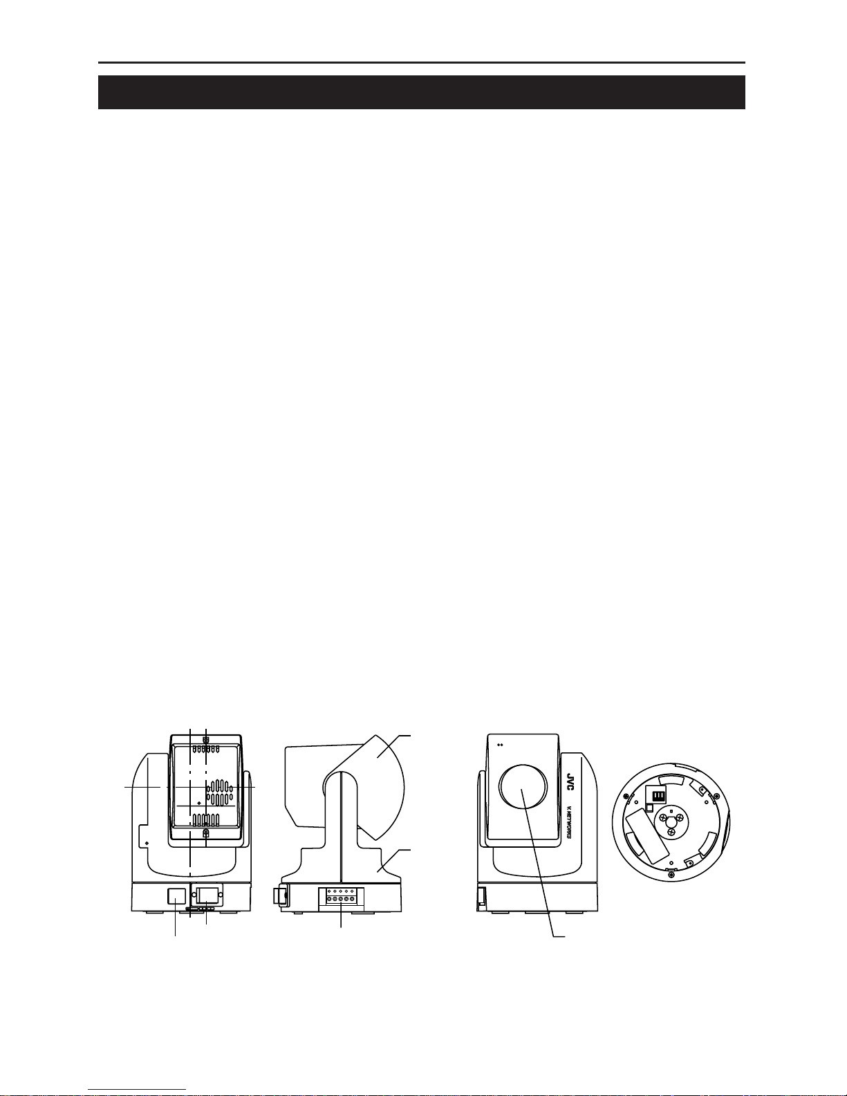
Names of VN-C30U parts
100BASE-TX
10BASE-T/
DC12V
Rear view
DC 12 V IN jack
10BASE-T/100BASE-TX port
Front view Bottom view
Lens cover
Body
Alarm IN/OUT jack
Side view
Lens unit
123
32
1
MODE SW
H10M
A F 100
Page 13

13
A : Auto Negotiation
M : Manual
F : Full Duplex
H : Half Duplex
100 : 100BASE-TX
10 : 10BASE-T
100FA
M10H
MODE SW
1
2
3
321
123
32
1
MODE SW
H10M
AF100
Connection to Ethernet
VN-C30U can be connected to both 10BASE-T and 100BASE-TX network.
To ensure this, the factory setting is set to Auto Negotiation. However,
depending on the used HUB, the unit may fail to work at this setting. For this
reason the LAN connection setting switch "MODE SW" is provided on the
bottom of the VN-C30U main unit. If VN-C30U cannot be connected or motion
image are not smooth, change the settings of the "MODE SW" switch as
shown below to find the appropriate condition.
The maximum data rate for sending from VN-C30U is 4Mbit/s, but it
may not be possible to obtain smooth MPEG live images in the Half
Duplex mode. We recommend to select one of the following mode;
(1) 10BASE-T Full Duplex
(2) 100BASE-TX Full Duplex
(3) Auto Negotiation
(In the (3) Auto Negotiation mode, it is recommended that the HUB,
etc., to which VN-C30U is connected be a device for which the link
can be established in the above-mentioned condition (1) or (2).)
Page 14

14
Installation and setup
1. Installation
Use the optional bracket (Model VN-BK30) for installation.
Make the power and network connections after completion of the installation work.
Caution
Install in a location with sufficient strength to prevent falling.
VN-C30U units can only be installed as shown in the diagram below, or
inverted. Do not install facing sideways.
Tilted installation is not possible.
1 Attach the ceiling fixer with the hole
pointing toward the front of the camera.
4 Mount the VN-C30U on the ceiling fixer
by rotating clockwise, then tighten the
screw of the camera body fixer.
2 Mount the camera body fixer
on the VN-C30U.
3 Attach the drop-prevention wire of the
ceiling fixer to the camera body fixer.
drop-prevention wire
V.NETWORKS
V.NETWORKS
Page 15

15
2. Connecting to the network
Turn on the power of only one VN-C30U unit.
When network connection is completed and the power is turned on, the
VN-C30U unit will be connected to the network at the following IP address.
Factory Default IP address 192. 168. 0. 2
•
About the power supply connection cable
• Length: 30m(98 feet) or less.
• Recommended model: UL1007, UL1015 or equivalent cable with wire
equivalent to ID AWG #20 or larger.
Caution
When shipped from the factory, the IP address of all VN-C30U units is set
to 192.168.0.2 Consequently, if multiple units are installed in the same
LAN environment and the power is turned ON at the same time, duplication
of IP addresses will occur and correct access will not be possible. Always
turn the power on for only one unit at a time. Once duplication of IP
addresses has occurred (and after confirming that only one VN-C30U
exists in the same LAN environment), wait a while (10 minutes or longer),
or turn off the power of all the network devices on the same LAN
environment, before turning the power ON again. If this is not done, it may
not be possible to access the VN-C30U.
100BASE-TX
10BASE-T/
DC12V
10 BASE-T, CAT-5 cable
12VDC
power supply
❉ Use a straight cable when
connecting to a hub.
Use a cross cable when
connecting directly to a PC.
Power supply connection cable
Caution
VN-C30U unit is intended to be supplied by a Listed Direct Plag-In Power
Unit marked “Class 2” and rated from 11 to 15 V dc, 2 to 2.5 A.
Page 16

16
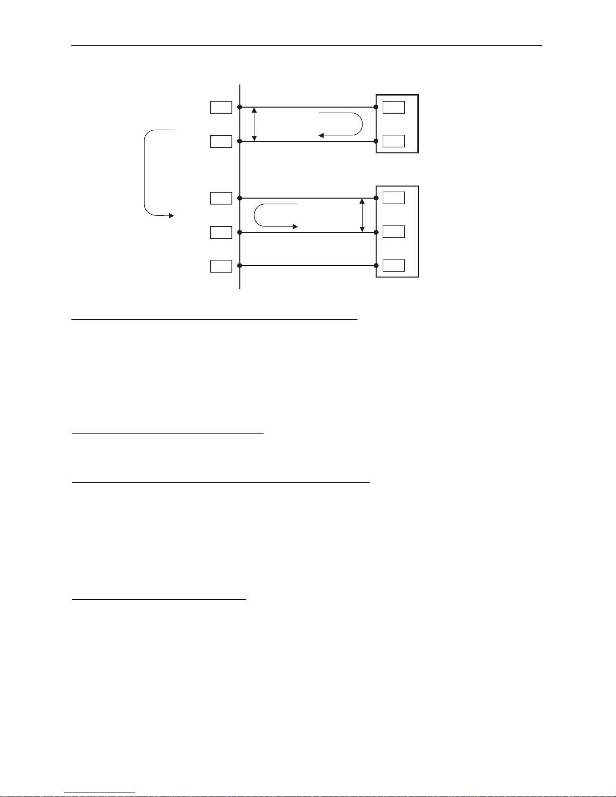
Sensor insert button
External
device
OUT 2
External
device
OUT 1
External
device
IN
Caution
External noise may affect the alarm working properly even with a cable
length of 50m or less. In such cases, it is necessary to either change to
the use of shielded cable to prevent influence by noise or to change the
wiring route to avoid passing close to the source of the noise.
3. Alarm IN/OUT connection
Connect external devices to the alarm IN/OUT as shown below.
•
Cable connection and disconnection
Press the sensor insert button when connecting and disconnecting cables.
After connecting or disconnecting, make sure the sensor insert button
returns to its original position.
•
About the alarm IN/OUT connection cables
• Length: use cables with a length of 50 m(164 feet) or less.
• Recommended model: UL1007, UL1015 or equivalent cable with wire
equivalent to AWG #22 - AWG #18.
Page 17
17
VN-C30U Summary of Alarm Input / Output Functions
VN-C30U
Alarm Input Alarm Output
1.2
G
G
OUT
OUT
COM
COM
GND
Sensor Device
Alarm Device
Relay Alarm function with
alarm input
GND
IN
5 V
1 mA
MAX.300 mA
MAX.12 V
Interface condition of Alarm Input Terminal
Non-voltage, relay “a” contact input
Or non-contact, semiconductor “a” contact input
Or NPN open-collector input
Active low level, latch/momentary(500 ms or more)
Circuit current 1 mA at low level, applied voltage
5 V at high level.
Examples of Sensor Devices
Infrared sensor, door sensor, metal sensor
manual switch, etc.
Interface condition of Alarm Output Terminal
Equivalent to NPN open-collector outpuut
(The output logic is set by the Setup Tool software)
Allowable input voltage: 12 V DC or less
Allowable current drain: 300 mA or less
Momentary(2-5000 msec)output
(The time is set by the Setup Tool software)
Examples of Alarm device
Alarm, indicator, light, buzzer, etc.
Note:
The types of relay contact mechanisms are expressed as “a” contact, “b”
contact, “c” contact, etc.
“a” contact: The contact is normally”Open” and is “Closed” when an event
occurs.
“b” contact: The contact is normally”Closed” and is “Open” when an event
occurs.
“c” contact: The contact status is inverted when an occurs.
Page 18

18
VN-C30U Examples of Alarm Input Terminal Interface
VN-C30U
OUT
GND
OUT
GND
5 V
1 mA
DC 5 V
R
R
GND
GND
Sensor device interface circuit
( Example 1 )
Sensor device interface circuit
( Example 2 )
1.2
G
Alarm Input
Equivalent circuit
Recommended connection cable
Maximum length: 50 meters(164 feet)
Recommended cable:
PULL UP
UL1007,UL1015 or equivalent
AWG#22 to AWG#18 or equivalent
Relay, Switch, etc
Page 19

19
VN-C30U
Alarm device interface circuit
( Example 1 )
Alarm device interface circuit
( Example 2 )
Alarm device interface circuit
( Example 3 )
Output time ( 2 to 5000 ms )
H level
H level
L level
At Low level
At High level
L level
Alarm Output
Equivalent circuit
Recommended connection cable
Maximum length: 50 meters(164 feet)
Recommended cable:
UL1007,UL1015 or equivalent
AWG#22 to AWG#18 or equivalent
Note: Alarm setup menu of the V.NETWORKS setup tool
When an alarm device with a similar structure to interface
circuits shown here is connected, the OUT terminal of
VN-C30U varies as shown below according to the output
port setup.
Buzzer, Lamp,
LED, etc
Buzzer, Lamp,
LED, etc
VN-C30U Examples of Alarm Output Terminal Interface
Page 20

20
4. Setting the VN-C30U IP address
4-1 Changing the IP address of the PC
Display the network settings panel by selecting Settings from the Start
button, then selecting Control Panel and Network, in that order.
2 Before making a change, always
make a note of the original IP
address.
Change the IP address to
192. 168. 0. 3.
Set the subnet mask to a value
suitable for the setting operation. If
the value is unknown, check with the
network administrator.
1 Select the TCP/IP item, then click
on Properties.
3 Click on OK and then
reboot the PC.
Page 21

21
5. Installing the software
5-1 Installing the controller software
Load the VN-C30U Controller CD-ROM into theCD-ROM drive.
The setup program is in the \JVC folder on the CD-ROM.
Execute \JVC\Setup.exe and follow the displayed instructions to setup
the software.
Page 22

22
5-2 Installing the V.NETWORKS Setup Tool
Execute the \JVC\setup\Setup.exe file on the CD-ROM, and then complete
the installation as directed by the messages on the screen.
6. Setting the V. NETWORKS Setup Tool
When installation is completed, select Start - Program - V.NETWORKS
to invoke the VN-C30U Setup Tool.
Enter the VN-C30U IP address.
The factory default IP address
192. 168. 0. 2
Settings are updated at the
time when "OK" is clicked.
For alarm
settings,
see page 26.
Resets the
image.
Select the compression method for the
camera image.For details on the setting, see
page 23.
The camera ID corresponds to the
identification code located on the
VN-C30U body. Only alphanumerics
can be entered.
The user does not participate
directly.
Normally, consecutive numbers
such as CAM00001, CAM00002.....
will be set.
Resets the
VN-C30U
unit.
For setting of
password,
see page 30.
Set the subnet
mask to a value
suitable for the
settingoperation.
If the value is
unknown,
check with the
network manager.
Change to an IP
address assigned
or approved by
the network
administrator.
(192. 168. 0. 2
is used as an
example in the
diagram.)
Page 23

23
When MPEG is selected
6-1 Setting the Image Compression Method
VN-C30U allows selection of either the MPEG1 compression or the JPEG
compression. (Hereafter, MPEG1 will be referred to as MPEG in this
manual.) On the V.NETWORKS Setup Tool screen, select MPEG or JPEG
in the "Image Compression" area, and then click the Details button to set
the details for the compression method.
GOP consists of three types of pictures, namely I, P and B.
I picture: Image composed only by
the in-frame compression data.
(Data size: Large)
P picture: Image compressed by referencing past picture data.
(Data size: Medium)
B picture: Image with data compressed by using past and future I or
P pictures. (Data size: Small)
This is to select the data structure for the intra-frame compression of the
image data.Group of Pictures (GOP) denotes a group that contains at least
one frame of the image (I picture) frames of the data of the in-frame compression that becomes the source of the intra-frame compression. Press
the Details button and select GOP.If the bit rate is the same, the image
quality will be higher when there are more B frames and as the delay time
becomes large for the composition of the final lines of the frame, this setting is recommended for recording.
Page 24

24
Slice header frequency
Normally use with the
setting at 16.
Closed GOP
When set to ON, individual
GOPs are created.Normally
use with OFF selected.
Setting the bit rate
320 x 240 can be set within the range of 260
kbit/s - 3500 kbit/s, and 160 x 120 can be set
within the range of 66 kbit/s - 1000 kbit/s.
However, the lower limit value may fluctuate
a little depending on the relevant image. If
you want to know the exact lower limit value
for the relevant image, make the recording
and perform the following calculation.
Recording file's number of frames/30 =
Recording time
File capacity (kbyte) x 8 bit/Recording time =
The bit rate (bit/s) of the acquired image
Resets settings to
the factory default
settings.
Makes the changes to settings valid.
Detailed settings are displayed.
When the settings of other items are
changed, click the Apply button.
Makes the changes to
settings valid.
Returns to the V.NETWORKS
Setup Tool screen.
Page 25

25
When JPEG is selected
Makes the changes to
settings valid.
Returns to the V.NETWORKS
Setup Tool screen.
Resets settings to the
factory default settings.
The compression rate is inversely
proportional to the picture quality.
The frame rate is proportional to the
compression rate.
Compression rate (1) - (7)
Image quality (High) - (Low)
Frame Rate (Low) - (High)
Page 26

26
6-2 Alarm Setting
Alarm function
This function is to receive or send an alarm signal from/to alarm input/
output over network. Use the V.NETWORKS setup tool for the fundamental
settings.
When the Alarm button of the
V.NETWORKS setup tool is clicked,
the screen shown below will be
displayed.
Page 27

27
The Alarm 1 and Alarm 2 settings
determine whether or not the
alarm function on Alarm 1 and
Alarm 2 are effective (ON or OFF).
When ON is selected, “Alarm
Output” (to send a signal to Alarm
out) and “Go to a preset position”
(one of the 10 preset positions) are
available.
❉For camera preset positions, see
"Position Memory Settings" on
page 44.
When the Alarm 1 and Alarm 2
receive signals in sequence, use
the Relay Alarm Function to make
the different settings from the
above mentioned Alarm 1 and
Alarm 2 settings.
Place a check beside Use Relay
Alarm and specify the alarm
occurrence sequence and the
time interval.
When a relay alarm is generated,
the alarm output and movement
of the camera to the preset
position can be controlled using
check boxes and scrollbars.
Caution
When Relay Alarm is set, following alarm operations will not activate.
Example: If relay alarm is generated in the order of Alarm 1 Alarm 2,
the operating mode becomes: Operation of Alarm 1 Operation of relay
alarm, and operation of Alarm 2 itself will not be executed.
Page 28

28
Out port setting includes the following settings:
OFF/ON: Determine whether or not an alarm is to be output.
Output value: Determine whether the High or Low signal will be output
when an alarm occurs. Enter the time for continuous signal output of
selected output value (High or Low) in the text box below.
Example: High 100ms
The High signal will be output for 100ms. After that, the output
value will change to Low.
Initialization: Determine whether or not the alarm signal will be output
one time when the power is turned on.
❉ Set the values of Out port setting in accordance with the device to which
the output is to be sent.
Retry: Determines the number of retries (1 - 3) to be made when alarm
input arrives.Depending on the LAN environment, alarm retry may fail. To
prevent this, it is possible to set the number of alarm retry attempts to 3
times. However, even when set to multiple times the client (VN-C30U
controller) will only operate once.
Alarm force output: Press the Output button for compulsory alarm output
from the camera alarm Out port in accordance with the current alarm Out
port settings. This can be used for checking devices connected to the output
port.
Page 29

29
The list of alarm broadcast client (IP address and
port number) currently registered in the camera can
be displayed by pressing Client List. The PCs that
satisfy the following conditions are displayed.
• The VN-C30U controller has been started and is
connected to the VN-C30U subject to setup.
• Checks are placed at Settings and Alarm Reg.
PCs can be deleted from the
broadcast client list by selecting the
IP address and pressing Delete.
Return to Alarm Setting window by
pressing OK.
Caution
Once the PC is deleted from the Broadcast client list, the alarm does not
function.
Page 30

30
Password function
An access protection using a password is provided to regulate
connecting PCs (users). Password setting and cancellation is performed
by the V.NETWORKS setup tool. Passwords for User, Operator and
Administrator can be set for each of the privilege levels.
Caution
Never forget the current password because the current password setting
cannot be changed unless it matches the password setting.
The password setting screen is
displayed by clicking the User,
Operator or Administrator
button on the Password Setting
screen of the V.NETWORKS
Setup Tool.
The change will be made
when Yes is clicked.
6-3 Setting the Password
To set password protection or
change the password, enter
the same both above and
below.(within 8 half-size
alphanumeric characters)
The entered characters are
shown as "*".
To cancel the password
protection, make the setting so
that nothing is entered at all.
For a VN-C30U for which password protection is set, the password requesting
screen appears. If the Administrator password does not match, it will not be
possible to perform the VN-C30U setup.The password will not be requested
in the condition in which only the password for user or operator is set and the
administrator password has not been set.
Contents of Access Rights
Can view the images.
Can perform all the operations allowed by the VN-C30U.
Can perform all of the above and make all the settings
allowed by the Setup Tool.
Privilege Level
User
Operator
Administrator
Page 31

31
6-4 Making the set IP address valid
When the IP address is changed, the pan and tilt mechanism will work
and the IP address becomes valid after the VN-C30U is reset.
Restoring a work PC IP address
Using the same procedure as in 4-1, select Settings from the Start button,
then select Control Panel and Network, Change to the original TCP/IP prop-
erties setting that you made a note and then restore a work PC IP address.
After restoration is completed, follow the messages of OS and reboot the
PC.
Search function
The Search button is used to find the V.NETWORKS IP addresses currently
connected to the network.
When Search button is pressed, the Search screen will be displayed. When
Start Search button is pressed, a list of the V.NETWORKS IP addresses
currently connected to the network will be displayed. Timeout is used to
set the search time and can be set to 0 - 30 sec.
Caution
When your own PC and a V.NETWORKS of a different subnet are
connected on a LAN, connection will not be possible even if the
search is successful.
In such cases, change to an appropriate IP address on your PC and
then try connection.
Caution
The V.NETWORKS Setup Tool is software that is only required when the
setup is performed. Therefore, please uninstall the software following
completion of the setup unless there is special reason for leaving it on
the PC. When setting the second or following units, reboot the PC and
then return to 2 (page 15). After setting of all the VN-C30U units is
completed, proceed with the next procedure.
6-5 Special Notes on the V.NETWORKS Setup Tool
Page 32

32
7. Registering connection points
Start the VN-C30U controller (vn-c30u.exe). Select New from the File
item in the menu and then specify the connection point.
The folder "VN-C30U Name" will be
created automatically in the folder
specified here. Recorded files will be
saved here. (Refer to page 50 concerning
recording.)
"Start recording on connection"
determines whether or not recording
will start automatically upon the
connection of VN-C30U.
Enter the IP address and name of the
VN-C30U connection point.
(192.168.0.2 is used as an example
in the diagram.)
When using a network backbone that does not offer sufficient capacity to
enable reception of the MPEG images, the images received within the
buffering period are displayed together after the buffering period has
expired. If set to 4 seconds, for example, nothing will be displayed for 4
seconds after the connection is established, and after 4 seconds the
images that have been received up to then are displayed. Then there will
be another 4 seconds of buffering before images are displayed again.
This setting is ignored if the network backbone capacity is larger than the
bit rate of the MPEG images being received. The factory default setting is
1 second.(90 sec is the maximum value that can be set.)
Set the Network time-out (seconds). Set
a long Network time-out in case the
image does not display correctly when
connecting to the network.
See the next page.
Page 33

33
Clicking the OK button displays the
setting confirmation screen.
Click OK to complete the registration.
Page 34

34
Controller Software Operation
Starting connection and changing connection points
Refer to Software Installation on page 21 for the installation procedure.
When the VN-C30U controller (vn-c30u.exe) is executed, a logo will be
displayed and then the following screen will appear.
Connection points can be selected from
this pulldown menu.
❉ In the case of a connection point provided with a password, you are asked
to enter the password. To connect, enter the password for operator or
administrator use.
Page 35

35
Controller 1
After a connection point is selected, you will find the names of currently
connected VN-C30U, the pan/tilt operation angle step and the current Pan/
Tilt position.
Pan/Tilt operation
angle step
Pan/tilt, Zoom-in/Zoom-out operation buttons.
The slide bar is for quick zoom operation.
The Pan/Tilt operation angle step of connected VN-C30U can be changed
by clicking on the left and right (
) buttons.
Pan/Tilt position can be changed with the Pan/Tilt operation buttons (8 buttons).
Zoom in/Zoom out is performed by one step for each click of zoom button. If
you keep pressing the button, Zoom in/Zoom out can be performed
continuously.
320
O
Pan range
Tilt range
90
O
The name of the
VN-C30U currently
connected to and the
controller operation
mode are indicated.
During viewing the
images, Live View is
displayed.
Current Pan/Tilt
position
Page 36

36
Controller 2
The VN-C30U controller has the
position memory function (up to
10 positions). By pressing this
button, the current position is
changed to the already
memorized position.
Refer to "Changing position
memory" on page 44
concerning changing the
contents of the position
memory.
The VN-C30U controller has
the Snapshot function. This
function allows you to
capture still images or save
them onto the hard disk.
For details, refer to "Snapshot
function" on page 52.
The size of VN-C30U controller can
be smaller by pressing this button.
It is possible to switch between
the normal and smaller controller.
Smaller Controller
Name of connected
VN-C30U
Image compression
method
Pan/tilt operation
buttons
Connection point selection
(pulldown menu)
Position memory
change button
Caution
During the position memory operation, the images may pause for a few
seconds. This is because the position correction function is automatically
being operated and this is not a malfunction.
Button to return to
the normal size
controller
Page 37

37
Convenient Function
When double-clicking in the window, the clicked position is brought to the
center of the image. (Only when JPEG image format is selected.)
Caution
It is not possible to move
beyond the Pan/Tilt limits but
this is not a malfunction.
Caution
During the Pan/Tilt operation, the images may pause for a few seconds.
This is because the position correction function is automatically being
operated and this is not a malfunction.
Page 38

38
Controller 3
The VN-C30U controller has
the recording and playback
function.
For details, refer to page 50
and 51.
Pan/Tilt operation angle step can
be set by clicking the value and
directly enter any value. After
entering (changing) the value,
press the Enter key.
Creating new connection points
Refer to "Registering connection points" on page 32.
If the cursor is briefly positioned over the VN-C30U
name, a balloon display of VN-C30U names will be
displayed.
When Placing the mouse cursor at the edge of the window the arrows
allow the size of the image to be changed as desired (the size
of the image captured from VN-C30U does not change). This button
returns the changed size of the window to the original size.
(Only when MPEG image format is selected.)
Page 39

39
Deleting connection points
Select File from the menu and
then select Delete.
Select a connection
point to be deleted
and then click on OK.
Make sure the desired point is
being deleted, and then press
OK.
Caution
The connection point cannot be recovered once it is deleted.
Page 40

40
Image quality • Lens adjustment
Select Settings from the menu and
then select Quality.
Image quality adjustment
Color saturation adjustment
As the value gets higher,
saturation gets stronger.
A small value makes it weaker.
The compression rate is inversely
proportional to the image quality.
As the value gets smaller, the image
quality increases but the data size
becomes larger.
When AWB is
checked,
the auto-white
balance function
will operate.
When the
checkmark is
removed from
AWB, manual
white balance
adjustment
becomes
possible by
means of the
R Gain/B Gain
slide bar.
Set at 1/60 in the case of
normal recording. In regions
with fluorescent light with a
commercial frequency of 50
Hz, please switch the setting
to 1/100. Set to 1/60 in 60 Hz
regions. This will reduce
flickering caused by
fluorescent light.
The setting
will be
effective.
Clicking Default returns the image
quality to the factory default settings.
•
When AGC is checked,
internal amp gain is
automatically adjusted
in accordance with the
brightness of the
surroundings.
•
When BLC is checked, the
backlight compensation
function is activated.From
the pull-down menu, the
metering area can be
specified.
(Select between 5 types.)
Brightness is automatically
adjusted with the specified
metering area (shaded
area) acting as reference.
❉
When AGC is not checked,
BLC cannot be checked.
Page 41

41
Lens setting
•When Auto is selected for Iris, the amount of light entering the camera
will be kept constant. When Auto is not selected, the brightness of the
screen is maintained at a fixed level that can be adjusted by using the
slide bar.
•When Auto is selected for Focus, the slide bar becomes inoperative.
When Manual is selected, the slide bar can be operated.
Advice
For locations where many people are passing by or operation of zoom at
Tele, we recommend to select Manual Focus in order to prevent continuous
auto focusing.
The current condition of the
lens is shown in the window.
The lens moves when the
setting items are operated.
Page 42

42
Frame Rate Setting
Select Settings from the menu
and then select Frame Rate.
Caution
The actual frame rate depends on the operational environment (PC
specifications, image compression, network infrastructure, etc.) and may
be different from the transmission frame rate. In practice, the higher
transmission frame rate is set up, the more bandwidth is required.
Therefore, try to set the lower transmission frame rate if relatively low
bandwidth is available for VN-C30U.
The frame rate can only be set for JPEG images. It is fixed at 30 Frame/s in
the case of MPEG images.
This is to set the upper limit of
transmission frame rate from
VN-C30U.
Page 43

43
Changing resolution and inverting the image
Select View from the menu.
The resolution can be selected
from 160 x 120, 320 x240 or
640 x 480. Depending on the
installation, select Normal or
Upside Down.
On-screen resolution change
The resolution can also be changed on the screen with the
following procedure.
Click the right button of the
mouse on the screen and select
one of the following: 160 x 120,
320 x 240 or 640 x 480.
Clicking Properties displays the
MAC address, IP address, unit
name, program version, and
storage destination.
(The pull-down menu is not
displayed in the case of MPEG
compression.
Caution
640 x 480 cannot be selected for MPEG images. Upside Down is not
possible either.
Page 44

44
Changing position memory
Select Setting from the menu and then
select Position Memory.
Procedure for Position
memory change
1 Use the position memory
buttons, Pan/Tilt/Zoom
setting and lens setting to
set the status in position
memory.
2 Press one of these memory
buttons in which the status
set in step 1 is to be
memorized.
3 Press OK to close the
position memory setting
window.
Caution
• When the zoom scroll bar is set to the Tele end, the lens position may
not be the same after changing its position.
1 2
3
Page 45

45
Alarm setting
The alarm settings determines the actions to be performed when an alarm
signal is received from Alarm 1 or Alarm 2 input of VN-C30U.
Select Settings from the menu, then
select Alarm Settings.
There are four functions as follows:
• Message
Pop-up the message entered in the text box.
(There is a limit on how many characters that can be displayed.)
• Recording
Start recording the images.
• Playing wave file
Play a specified wave file . Any wave files can be specified from the
Browse button.
• Execute application file
Execute a specified application file. Any execute (.exe) files can be
specified from the Browse button.
Select Non-Stop or Stop in 1
minute after the recording
starts,
Stop in 1 minute is used for
saving space on the hard disk.
When Stop in 1 minute is
selected, normal recording
specified on the controller
software also stops in 1 minute
after the alarm is received.
Page 46

46
To enable the Alarm 1, Alarm 2 and/or
Relay Alarm settings, it is necessary
to check (✔) Alarm reg.
Relay alarm setting
When relay alarm setting is performed using
the V.NETWORKS Setup Tool, this window
becomes active.
The program to be executed and the wave
file to be played back when a relay alarm is
generated can be set in advance.
(For these items, please see the previous
page.)
Caution
• When a large wave file (*.wav) is selected, the alarm operation may be
delayed depending on the PC specifications. Try to select a relatively
small wave file.
• In order to enable the Alarm 1, Alarm 2 and/or Relay Alarm setting it is
necessary to
1) Select "ON" in Alarm 1, Alarm 2 and/or Relay Alarm setting of
V.NETWORKS setup tool (refer to page 27),
and
2) Check (✔) Alarm reg.
• When relay alarm has been set, the second alarm operations is not
performed.
Example: When the Relay Alarm occurs in the sequence of
Alarm 1 Alarm 2, alarms operate in the sequence of
Alarm 1 Relay Alarm and Alarm 2 does not operate at all.
Page 47

47
Select Setting from the menu and then
select Time Stamp.
Time stamp setting
Sets whether the time stamp
should be displayed or not.
When Visible is checked, the
date and time are displayed
superimposed on the camera
image.
During playback, the date
and time of the recording are
displayed.
❉ In the case of MPEG, the
time stamp is only displayed
in the title bar.
In the MPEG mode, selection
of Font is disabled.
❉ Changing the time stamp display position
On the screen, hold down the Shift key and click the left button of the
mouse at the position where time stamp is to be displayed.
Sets the color of the characters of the time stamp
and the background color.
• Transparency ... The background becomes
transparent.
❉ In the MPEG mode, selection of color is disabled.
Page 48

48
Any of the following 7 display styles can be selected.
YYYY/MM/DD HH:MM:SS.mm
(year/month/date hour: minute: second. millisecond)
YYYY/MM/DD HH:MM:SS
(year/month/date hour: minute: second)
DD/MM/YYYY HH:MM:SS
(date/month/year hour: minute: second)
MM/DD/YYYY HH:MM:SS
(month/date/year hour: minute: second)
MM/DD HH:MM:SS
(month/date hour: minute: second)
HH:MM:SS
(hour: minute: second)
HH:MM
(hour:minute)
Page 49

49
Select Settings - Property.
Changing Property
The information related to connections and setting when the connection was
first defined can be changed. (However, it is only the VN-C30U information
in the offline mode that can be changed.)
Select the camera for which
the properties should be
changed from the VN-C30U
Name designations pull-down
menu.
Camera property and Save
in cannot be changed.
It is possible to make the
settings as when the
properties were first
created.
Following these changes,
click the OK button to
complete the changing of
properties.
Page 50

50
Recording function
This function is to continuously record the images of connected VN-C30U
onto automatically created folder with “VN-C30U Name.”
Press the "REC" button.
In the JPEG mode, the "REC"
characters are displayed in the
upper right corner of the window.
Press the STOP button to stop
recording. “REC” disappear.
❉ Avoid continuous recording for a long period of time. When playing back
a file recorded by continuous recording for a long period of time, the
memory of the computer may become insufficient, and playback may
not be possible.
❉ Never change the saved files and their name, otherwise all the saved
images may not be correctly playback.
❉The recorded file is saved in the
folder specified when the initial
setup was performed.
Blinks red during recording.
"Recording" is displayed when recording
starts.
Page 51

51
Playback function
Press the PLAY button.
Select the file type for the
image data.
(MPEG or JPEG)
When the OK button is clicked, the connection to the camera is
disconnected and the playback picture screen appears.
Click the OK button.
This window only appears during
viewing of the image from the
camera.
Select the file that you want to
playback from the storage
destination of the recorded
file.
The filename becomes the
start-to-stop times of the
recording.
Page 52

52
Playback picture screen
Snapshot function
The VN-C30U controller allows you to capture a still image and save it as a
still picture file.
If the VN-C30U is operating in the JPEG mode, the file will be saved in the
JPEG format, and if it is operating in the MPEG mode, it will be saved in the
MPEG format.
Click the Snap Shot button.
During playback, the slide bar
moves toward the right in
accordance with the playback
time.
By dragging the slide bar with the
mouse, the file can be played back
as desired.
Clicking Stop stops the playback and returns to the first
image.
Clicking Pause pauses the playback.
Clicking Play starts the playback.
Closes the playback picture
screen.
Page 53

53
Caution
• Saved images can be displayed with ordinary viewer software. However,
inverted images cannot be displayed inverted. Colors may also differ
from those seen on the VN-C30U controller screen.
•
Do not start other image viewing application while the VN-C30U Controller
Software is active. This is particularly important with Windows 95 as it
may cause a failure in saving snapshots. In this case, use the recording
function to save images.
Snapshot display is possible.
Up to 16 images can be shown as snapshot display.
When 16 snapshots are displayed, the camera
symbol disappears from the Snap Shot button.
A beep sound is heard if you click the Snap Shot
button at this time.
If you select File - Save from each of the
snapshot display menus, the Save dialog
box is displayed.
Specify the location.
Enter the file name.
Press Save to save the file.
Page 54

54
Troubleshooting
An IP address changed
with the V.NETWORKS
Setup Tool has been
forgotten.
The Search button of the V.NETWORKS Setup
Tool can be used to acquire the IP addresses
of V.NETWORKS cameras connected to the
network.
If the desired information cannot be found by
viewing the vsetup file, this must be handled
as a repair. Please consult your local dealer.
Recording is not
possible.
• It is possible to delete the folder used to
save images. Check to make sure the folder
exists.
• It is possible for the disk to become full.
Check the available capacity of the disk.
The password set with
the password protection
function has been
forgotten.
The disabling of the password protection
function is handled as a repair. Please consult
your local dealer.
For safety, be prepared to show proper
identification.
Time is required for
cancellation when
"Connecting..." is
displayed.
Once the connection operation starts,
cancellation is not possible for a period of
several seconds.
Page 55

55
The colors are not
satisfactory.
• Check the color adjustments of the display
or video card.
The colors displayed by different PC
display monitors and video cards will differ
to some degree. Improvement is sometime
possible by adjusting the color settings of
the display monitor. Depending on the
video card, colors can sometimes be
adjusted using Screen Properties (click the
right mouse button on the desktop.)
• Switching to True Color (24-bit) display
Colors are sometimes not natural at the
High Color (16-bit) or lower setting. It is
recommended that you use True Color.
• Adjusting white balance
Colors can also be changed by adjusting
Manual white Balance from the image
quality adjustment screen.
When different light sources have been
used.
(For example, when alternately using
sunlight outdoors and fluorescent lighting
indoors.)
Time is sometimes required for auto
tracking white balance to start operating.
In such cases, white balance can
sometimes be made to work quickly by
removing the check from Auto in the image
quality adjustment screen and then
replacing the check.
• Depending on the subject, the colors may
appear to vary slightly in some cases. This
is not a malfunction.
The image size and
position change
spontaneously.
When one VN-C30U unit is connected to
several PCs, the last PC to operate and set
the VN-C30U unit will have priority.
Page 56

56
Out of focus.
The autofocus sometimes does not operate
correctly in dark places and when blank
surfaces such as walls are photographed. In
such cases, focus manually.
The focus may be off slightly when manual
focus is used at the TELE position, but this is
not a malfunction.
VN-C30U connection is
not possible or the
connection has been
broken.
When there are multiple occurrences of
broadcasts, collisions, etc., or when the
network status is not normal, it may become
impossible to connect the VN-C30U or the
connection may be broken.
When display of moving
MPEG images is not
smooth.
When the computer's specifications or the
bandwidth of the network is insufficient, the
live images may appear as in slow motion or
frames may drop out, etc.
(This is not a malfunction.)
The VN-C30U controller
does not start up.
When using the snapshot utility supplied with
the CANOPUS's video card, the dll file name
will cause conflicts, and normal operation of
the VN-C30U controller may be prevented.
Use the VN-C30U controller in the condition
in which the snapshot utility supplied with the
video card has been closed.
Page 57

57
Specifications
LAN standard
Communication protocol
Image Sensor
Lens
Minimum focusing distance
Pan/tilt operation angle
Image compression
Output image format
Alarm input
Alarm output
Power supply voltage
Power consumption
Operating temperature
Mass (weight)
IEEE 802.3, IEEE 802.3u standards
UDP/IP, TCP/IP
1/4-inch, 380,000-effective pixels CCD
15:1 zoom lens, f = 4.1 mm - 61.5 mm, F 1.4 - 2.4
0.8 m
Pan: 320 ° Tilt: 90 °
JPEG, MPEG1
640 x 480, 320 x 240, 160 x120
Non-voltage a contact input.NPN open collector input
Low level. latch/momentary (500 ms or more)
Low level circuit current 1 mA
High level impressed voltage 5 V
NPN open collector output (allowable impressed
voltage: 12 V; allowable input current: 300 mA)
DC 12 V
2.0 A (max.)
0° C – 40° C
Approx. 800 g.
100BASE-TX
10BASE-T/
DC12V
External dimensions (Unit: mm)
Page 58

58
Page 59

59
Page 60

is a registered trademark owned by VICTOR COMPANY OF JAPAN, LTD.
is a registered trademark in Japan, the U.S.A., the U.K. and many other countries.
Printed in Japan
LHT0005-001A
VICTOR COMPANY OF JAPAN, LIMITED
 Loading...