

Page 1
SERVICE MANUAL
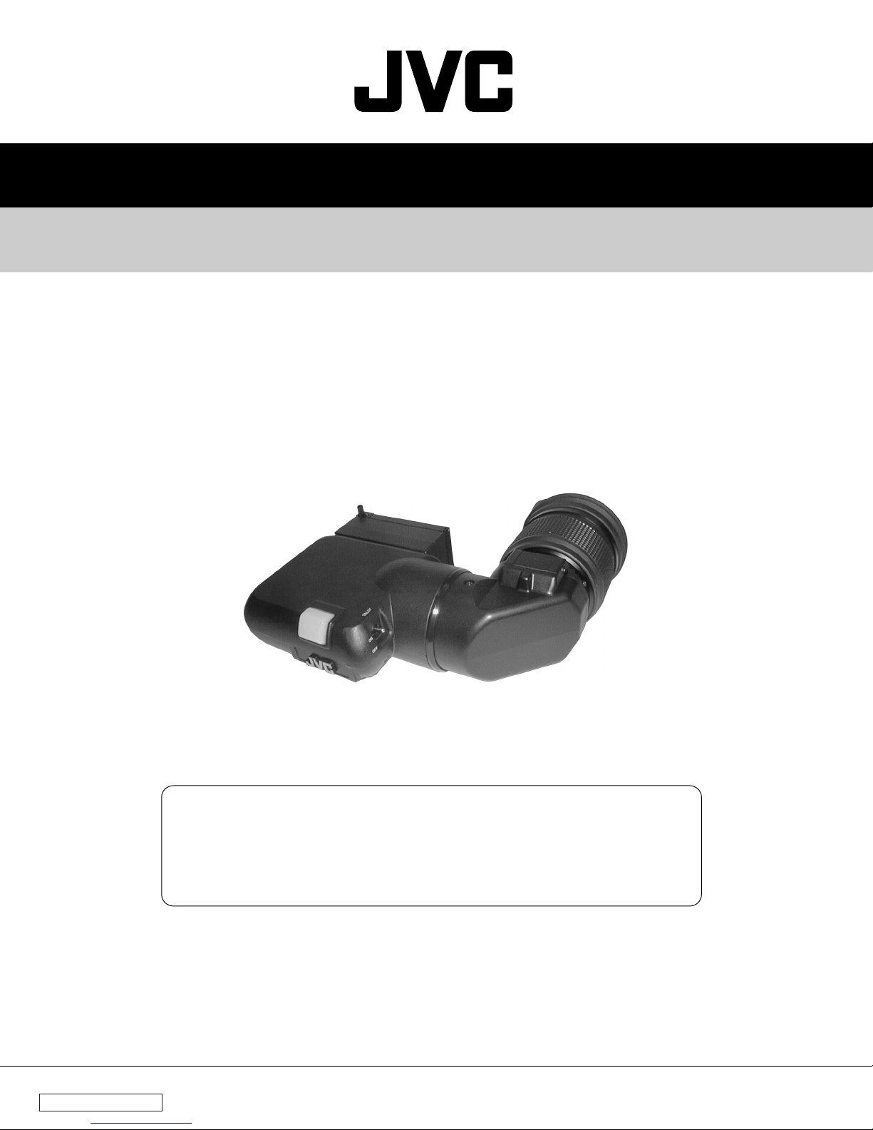
VIEWFINDER
VF-P116U(A
VF-P116E(A
)
)
VF-P116 is modified from following serial number to use the case and the PCBs
commonly with the VF-P116W. VF-P116 (A) is indicated on the serial no. plate.
VF-P116U xxxx0781 and after
VF-P116E xxxx2051 and after
This service manual is exclusively for VF-P116 (A) only.
100% recycled paper
COPYRIGHT © 2000 VICTOR COMPANY OF JAPAN, LTD.
No. 60109B
December 2000
Page 2

TABLE OF CONTENTS
Section Title Page
INSTRUCTIONS
1. DISASSEMBLY ................................................................................................................................................... 1
2. ELECTRICAL ADJUSTMENT .............................................................................................................................. 3
3. CHART AND DIAGRAM ..................................................................................................................................... 6
4. EXPLODED VIEW AND PARTS LIST .................................................................................................................. 8
5. ELECTRICAL PARTS LIST ................................................................................................................................ 10
6. PACKING .......................................................................................................................................................... 12
COMPARISON WITH PREVIOUS MODEL
DIFFERENCE OF EXTERNAL VIEW VF-P116U/E VF-P116U(A)/E(A) DESCRIPTION
TALLY LED 4 LEDs 2 LEDs with white cover
DIFFERENCE PARTS VF-P116U/E VF-P116U(A)/E(A) DESCRIPTION
PACKING
Instructions
SC96773 SC96985
ASSEMBLY <M1>
TALLY BRACKET (Symbol 14)
UPPER CASE (Symbol 15)
BOTTOM CASE (Symbol 16)
TUBE (Symbol 53)
TALLY COVER (Symbol 54)
ELECTRICAL PARTS
VF MAIN board assembly
VR board assembly
TALLY board assembly
SC44730-001
SC20430-011
SC20431-003
–
–
SCK2481-01-00A
SCK2481-02-00A
SCK2481-03-00A
SC46364-001
SC20430-012
SC20431-004
SC45909-070
SC32217-001
SCK2554-01-00A
SCK2554-02-00A
SCK2554-03-00A
Same as VF-P116W
Same as VF-P116W
Same as VF-P116W
Same as VF-P116W
Same as VF-P116W
Page 3
SECTION 1
´
Ï
5
5
DISASSEMBLY
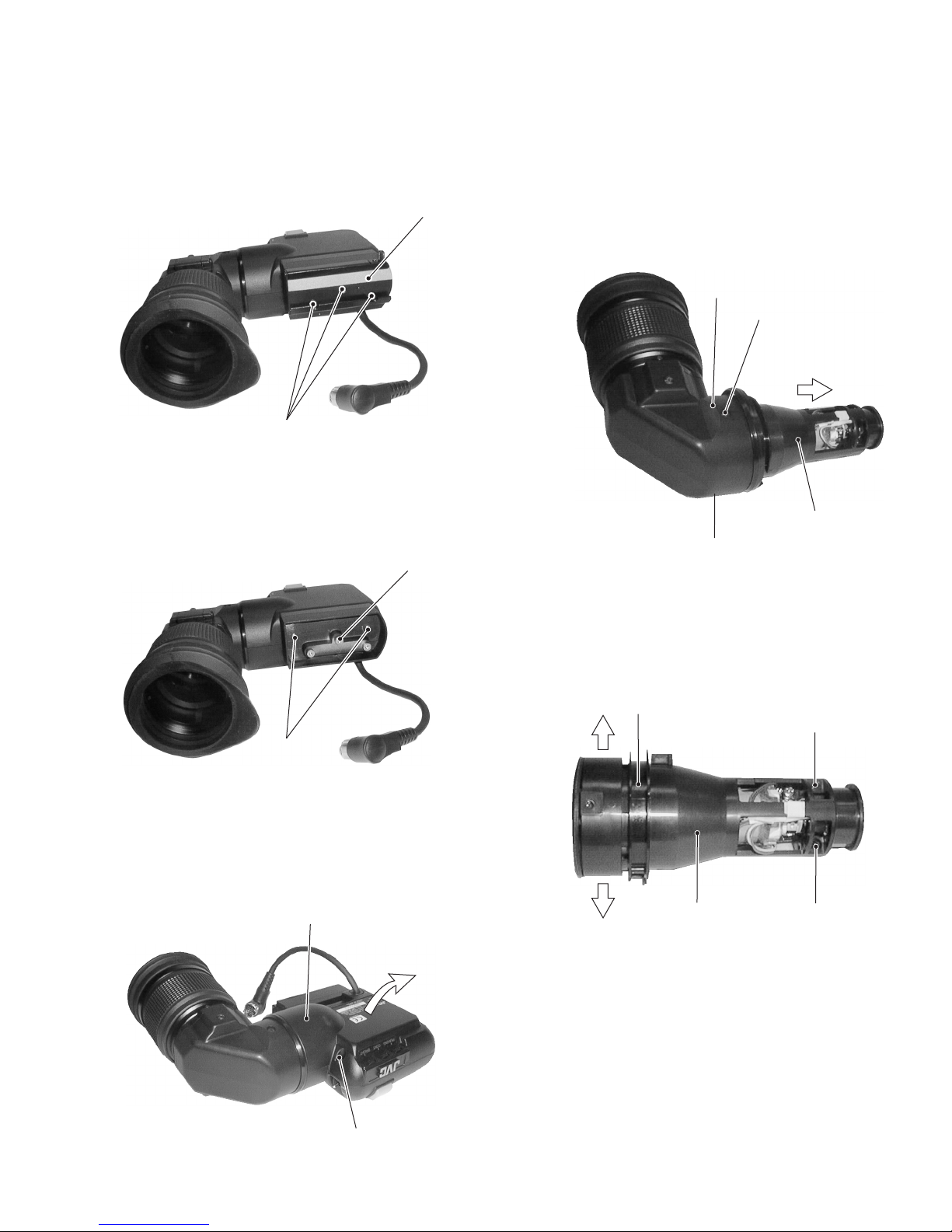
1.1 REMOVAL OF COVER
1. Remove three screws
2. Remove two screws
2
and detach the slide base Å.
ˆ
1
Fig. 1-1
and detach the VF base ı.
ı
Å
1.2 REMOVAL OF CRT
1. Open the bottom cover referring to “1.1 REMOVAL OF
COVER”.
2. Remove two screws
out the CRT together with the CRT holders
ror case
Î
.
from on the mirror case Î and pull
4
from the mir-
´
Î
4
´
4
Fig. 1-4
3. Remove one screw
opened in the direction of the arrow.
2
Fig. 1-2
, and the bottom case Ç can be
3
Ç
3. Remove the ring
4. Remove two screws
open the CRT holder
Ï
in the manner to open it.
Fig. 1-5
(one in the opposite side) and then
5
. (See Fig.1-5)
´
Fig. 1-3
3
1
Page 4
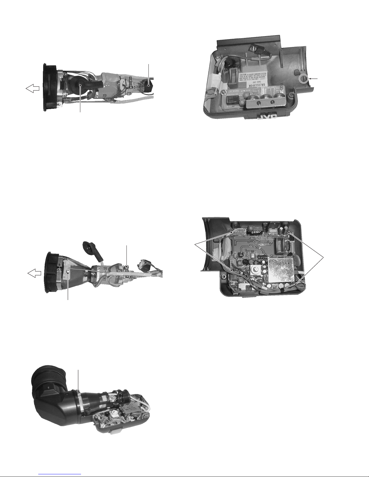
5. Remove the CRT socket ˝.
Ó
˝
PIN
Fig. 1-6
6. Shortcircuit the anode of the CRT to the chassis or the FBT
cover for discharge, and then disconnect the anode plug
Note: The anodic electrode is located inside the rubber
cover of the anode plug
careful not to get an electric shock.
7. Loosen one screw
and remove the soldering
Pull the CRT out of the deflection yoke in the direction of the
arrow (f).
fixing the CRT to the deflection yoke
6
ˆ
. When discharging, be
Ó
.
Ó
6
ˆ
Fig. 1-7
Fig. 1-9
.
1.3 REMOVAL OF MAIN BOARD
1. Open the bottom cover referring to “1.1 REMOVAL OF
COVER”.
2. Remove four screws
tached.
and the MAIN board can be de-
7
7
7
Fig. 1-10
When reassembling the CRT to the set, put the spring
onto the pin on the bottom cover without fail.
Ô
Fig. 1-8
2
Ô
Page 5

SECTION 2
ELECTRICAL ADJUSTMENT
2.1 ARTICLES REQUIRED FOR ADJUSTMENT
2.1.1 Measuring instruments necessary for adjustment
Measuring instrument
Oscilloscope
Capable of measuring 10MHz or higher
Requirement
bands, and calibrated
Frequency counter
Readable in 8 or more digits.
Constancy of 0.1ppm/1 × 10
-7
or more
at 0°C to 40°C
Digital voltmeter
Input impedance of 10 M or more,
and calibrated
2.2 LOCATION OF ADJUSTMENT PARTS
VR board
V. HEIGHT
VR501
V. HEIGHT2
RY501 VR502
CN501
PEAKING
VR102
2.1.2 Other necessities for adjustment
Camara and lens
Resolution chart or registration chart
• Adjustment by 4:3 mode
CN503 CN504 GND
CN101
CONTRAST
VR1
TP3
TP2
CN102
BRIGHT
VR8
MAIN board
CN401
CN2
H HOLD
V HOLD
VR3
VR5
H. LIN
VIDEO LEVEL
VR101
CN7
CN8CN3
SUB BRIGHT FOUCUS
CN4
CN5
CN1
TP1
CN6
VR7
VR6
3
Page 6
No. Item instruments &
Measuring
Input signals
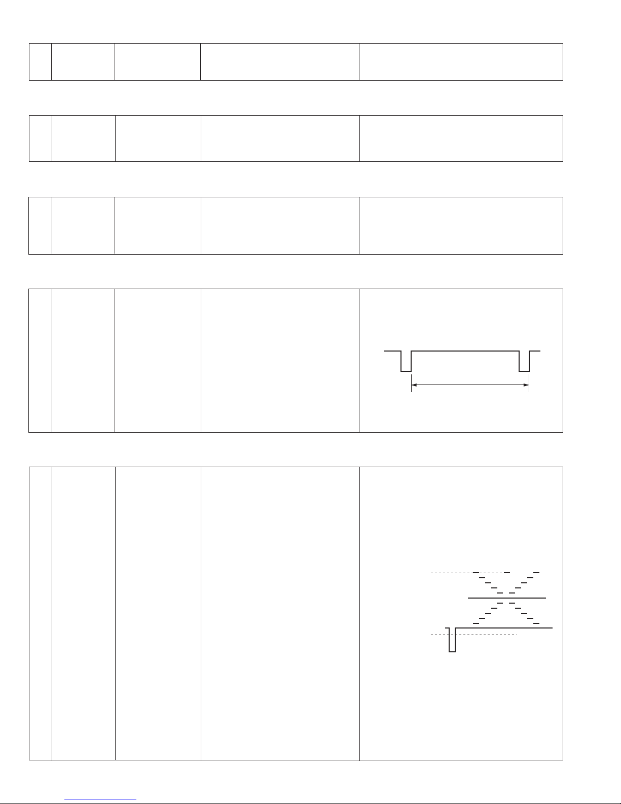
2.3 CHECK OF SUPPLY VOLTAGE
Measuring point (*)
Adjustment parts (-)
Adjustment level (+)
Adjustment procedure
1 12V supply
• Digital voltmeter 1) Check to see if the specified voltage is meas-
voltage check
2.4 ADJUSTMENT OF H.HOLD
1 H. HOLD
adjustment
• Frequency
counter
2.5 ADJUSTMENT OF V.HOLD
1 V.HOLD
adjustment
• Oscilloscope
(V-rate,10:1)
* Between pin 5 of CN1 and
GND [MAIN]
+ +12V ± 0.5V
* Between collector of Q10
[MAIN] and TP3(GND)[VR]
- H. HOLD(VR3)[MAIN]
+ 14.7 ± 0.3kHz
* TP2 and TP3 (GND)[VR]
- V. HOLD(VR5)[MAIN]
+ 17.5 ± 0.5ms(U.Ver)
+ 21 ± 0.5ms(E.Ver)
ured at the measuring point.
1) Adjust VR3 to obtain the specified frequency
at the measuring point.
1) Adjust VR5 to obtain the specified level at the
measuring point.
17.5 ± 0.5ms(U.Ver)
21 ± 0.5ms(E.Ver)
2.6 ADJUSTMENT OF VIDEO LEVEL
1 Video level
adjustment
• Gray scale chart
• Oscilloscope
(H-rate,10:1)
* TP1[MAIN] and TP3
(GND)[VR]
- VIDEO LEVEL(VR101)
[MAIN]
+ +10 ± 0.5V DC
1) Shoot the gray(scale) chart by the camera.
2) Observing the waveform on oscilloscope, adjust VR101 to obtain the specified level at the
measuring point.
+10 ± 0.5V DC
0V DC
4
Page 7
Measuring
Measuring point (*)
No. Item instruments &
Adjustment parts (-)
Adjustment procedure
Input signals
Adjustment level (+)
Measuring
Measuring point (*)
No. Item instruments &
Adjustment parts (-)
Adjustment procedure
Input signals
Adjustment level (+)
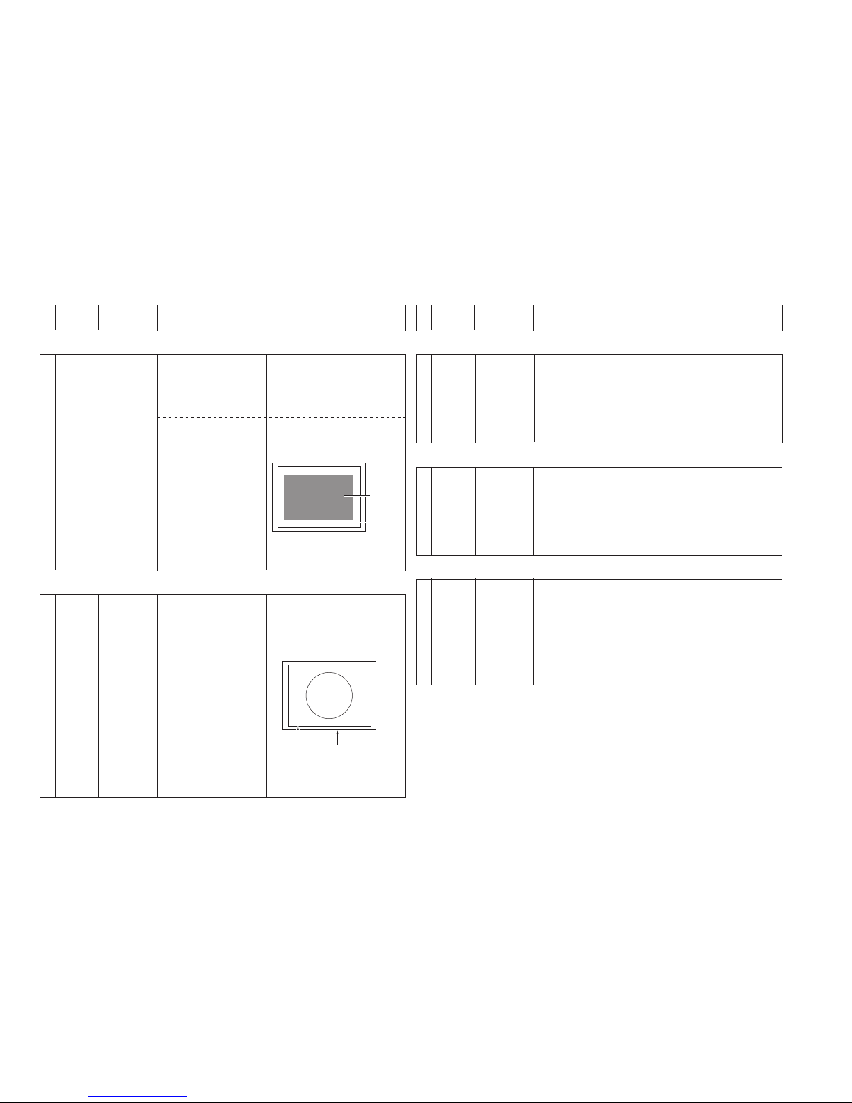
1 V. amplitude
adjustment
•Resolution chart or
Registration chart
1) Shoot the resolution chart or registration chart
so as to take the central circle of the chart as
large as possible.
2) Adjust the V. HIGHT control so that the central
circle of the chart shows a perfect circle.
3) If the central circle looks elliptical, fine adjust
the H.LIN control(L4) to correct it.
2.9 ADJUSTMENT OF V.AMPLITUDE (for 4:3)
1 Centering
adjustment
1) Set the BRIGHT and CONTRAST controls on
the front panel to the mechanical center position respectively.
2.7 ADJUSTMENT OF CENTERING
- V. HEIGHT(VR501)[VR]- BRIGHT(VR8)[VR]
CONTRAST(VR1)[VR1]
1) Reduce the raster part by tuning the H.LIN and
V. HEIGHT controls.
- H. LIN(L4)[MAIN]
V. HEIGHT(VR501)[VR]
1) Adjust the DY centering magnet of the deflection yoke so as to position the raster part in
the center of the CRT.
- DY centering magnet
[Deflection yoke]
1 H. linearity
adjustment
•Resolution chart of
Registration chart
1) Shoot the resolution chart or registration chart
so as to take the central circle of the chart as
large as possible.
2) Adjust the H.LIN control so that the linearity of
the picture is aligned in both the sides.
2.8 ADJUSTMENT OF H.LINEARITY
- H. LIN(L4)[MAIN]
1 Sub-brightness
adjustment
1) Set BRIGHT and PEAKING controls on the front
panel to the minimum position, while set the
CONTRAST control to the maximum position.
2) Adjust the SUB BRIGHT control so that the
raster is seen dimly.
2.10 ADJUSTMENT OF SUB-BRIGHTNESS
- SUB BRIHT(VR7)[MAIN]
1 Focus
adjustment
1) Shoot an object by the camera.
2) Set the CONTRAST and PEAKING controls on
the front panel to the mechanical center position respectively.
3) Turn up and down the brightness with the
BRIGHT control on the front panel while adjusting the FOCUS control to obtain the best
focus.
2.11 ADJUSTMENT OF FOCUS
- FOCUS(VR6)[MAIN]
Raster part
CRT screen
Protecive glass of CRT
Fluorescent screen of CRT
55
Page 8

VF-P116U(A)/VF-P116E(A)
VICTOR COMPANY OF JAPAN, LIMITED
No. 60109B
Printed in Japan
(S), C.Y
Page 9

INSTRUCTIONS
VF-P116
(A)
VIEWFINDER
For Customer Use:
Enter below the Serial No. which is located
on the top of the body.
Retain this information fo future reference.
Mode No. VF-P116 (A)
Serial No.
1. Read all of these instructions.
2. Save these instructions for later use.
3. All warnings on the product and in the operating instructions should
be adhered to.
4. Unplug this appliance system from the wall outlet before cleaning.
Do not use liquid cleaners or aerosol cleaners. Use a damp cloth
for cleaning.
5. Do not use attachments not recommended by the appliance manufacturer as they may cause hazards.
6. Do not use this appliance near water
– for example, near a bathtub, washbowl, kitchen sink, or laundry tub, in a wet basement, or
near a swimming pool, etc.
7. Do not place this appliance on an unstable
cart, stand, or table. The appliance may fall,
causing serious injury to a child or adult, and
serious damage to the appliance.
Use only with a cart or stand recommended
by the manufacturer, or sold with the appliance. Wall or shelf mounting should follow
the manufacturer's instructions, and should
use a mounting kit approved by the manufacturer.
An appliance and cart combination should be moved with care.
Quick stops, excessive force, and uneven surfaces may cause the
appliance and cart combination to overturn.
8. Slots and openings in the cabinet and the back or bottom are provided for ventilation, and to insure reliable operation of the appliance and to protect it from overheating, these openings must not
be blocked or covered. The openings should never be blocked by
placing the appliance on a bed, sofa, rug, or other similar surface.
This appliance should never be placed near or over a radiator or
heat register. This appliance should not be placed in a built-in installation such as a bookcase unless proper ventilation is provided.
9. This appliance should be operated only from the type of power
source indicated on the marking label. If you are not sure of the
type of power supplied to your home, consult your dealer or local
power company. For appliance designed to operate from battery
power, refer to the operating instructions.
10. This appliance system is equipped with a 3-wire grounding type
plug (a plug having a third (grounding) pin). This plug will only fit
into a grounding-type power outlet. This is a safety feature. If you
are unable to insert the plug into the outlet, contact your electrician to replace your obsolete outlet. Do not defeat the safety purpose of the grounding plug.
IMPORTANT SAFEGUARDS
PORTABLE CART WARNING
(symbol provided by RETAC)
S3126A
11. For added protection for this product during a lightning storm, or
when it is left unattended and unused for long periods of time,
unplug it form the wall outlet and disconnect the antenna or cable
system. This will prevent damage to the product due to lightning
and power-line surges.
12. Do not allow anything to rest on the power cord. Do not locate this
appliance where the cord will be abused by persons walking on it.
13. Follow all warnings and instructions marked on the appliance.
14. Do not overload wall outlets and extension cords as this can result
in fire or electric shock.
15. Never push objects of any kind into this appliance through cabinet
slots as they may touch dangerous voltage points or short out parts
that could result in a fire or electric shock. Never spill liquid of any
kind on the appliance.
16. Do not attempt to service this appliance yourself as opening or
removing covers may expose you to dangerous voltage or other
hazards. Refer all servicing to qualified service personnel.
17. Unplug this appliance from the wall outlet and refer servicing to
qualified service personnel under the following conditions:
a. When the power cord or plug is damaged or frayed.
b. If liquid has been spilled into the appliance.
c. If the appliance has been exposed to rain or water.
d. If the appliance does not operate normally by following the op-
erating instructions. Adjust only those controls that are covered
by the operating instructions as improper adjustment of other
controls may result in damage and will often require extensive
work by a qualified technician to restore the appliance to normal operation.
e. If the appliance has been dropped or the cabinet has been dam-
aged.
f. When the appliance exhibits a distinct change in performance
–
this indicates a need for service.
18. When replacement parts are required, be sure the service technician has used replacement parts specified by the manufacturer that
have the same characteristics as the original part. Unauthorized
substitutions may result in fire, electric shock, or other hazards.
19. Upon completion of any service or repairs to this appliance, ask
the service technician to perform routine safety checks to determine that the appliance is in safe operating condition.
SPECIFICATIONS
Input signal : Composite video, 1 V(p-p)
high impedance
CRT : 38 mm (1.5") diagonal(Black and
white 4:3)
Resolution : More than 600 lines
Indications : Tally lamp: Lights up during re-
cording
(can be turned ON/
OFF)
CRT (alert): BATT: Battery (cam-
era power)
goes down
REC/ALARM: Tape
end of VCR
Abnormal display
Power consumption : 12 V DC, 3.6 W
Operating temperature
:–5°C to 45°C
Mass : 770 g
TROUBLESHOOTING
Symptom
No raster. Dark screen.
Tally lamp does not
light up.
Check
Are the brightness and
contrast controls correctly
set?
Is the Tally switch set to ON?
Dimensions: (unit: mm)
VICTOR COMPANY OF JAPAN, LIMITED
®
is a registered trademark owned by VICTOR COMPANY OF JAPAN, LTD.
®
is a registered trademark in Japan, the U.S.A., the U.K. and many other countries.
© 2000 VICTOR COMPANY OF JAPAN, LIMITED
Printed in Japan
SC96985
Design and specifications are subject to change without notice.
PEAKING CONT BRIGHT
TALLY
ON
OFF
68
78
205
118
195
96
52
.
5
45
Page 10

Thank you for purchasing the JVC Viewfinder.
(These instructions are for VF-P116U and VF-P116E)
To gain maximum benefit from the viewfinder, it is suggested that you study this instructions carefully. After reading,
retain it for future reference.
FEATURES
• Adoption of a large-size tally lamp allows you to check the lit condition of the tally lamp from the side as well as the
top.
• Designed for easy operation
A 1.5-inch viewfinder designed to facilitate camera operation.
• Designed for easy viewability
The eyepiece can be titled in both directions for optimum viewability.
• Slide mechanism
You can make positional adjustments right and left to obtain optimum visibility.
PRECAUTIONS
• This unit is to be used exclusively for 4:3.
• Prevent water and metallic objects from entering the unit as this could lead to malfunctions.
• Do not expose the unit to excessive shock. Especially be careful not to apply shocks and vibrations when installing
or during transportation.
• Avoid using the unit in places subject to excessive humidity, heat, or strong magnetic or electric fields.
• Do not disassemble or modify the unit. Do not use the unit with its cover removed.
• Strong electromagnetic waves or magnetism (for example, near a radio or TV transmission antenna, transformer or
motor) can interfere with the image and generate spurious noise.
• Do not expose the lens or viewfinder to strong sunlight or place in a strong light source.
• Exposure of the lens or viewfinder to strong sunlight or other strong light sources will cause eye injuries.
• Continued exposure of the lens or viewfinder to sunlight will damage the internal condensing lens, resulting in
malfunction and possible fire.
• To save power, shut off the power supply when the system is not in use.
CAUTION:TO REDUCE THE RISK OF ELECTRIC SHOCK.
DO NOT REMOVE COVER (OR BACK).
NO USER-SERVICEABLE PARTS INSIDE.
REFER SERVICING TO QUALIFIED SERVICE PERSONNEL.
RISK OF ELECTRIC SHOCK
DO NOT OPEN
CAUTION
The lightning flash wish arrowhead symbol, within
an equilateral triangle is intended to alert the user
to the presence of uninsulated "dangerous voltage"
within the product's enclosure that may be of sufficient magnitude to constitute a risk of electric shock
to persons.
The exclamation point within an equilateral triangle
is intended to alert the user to the presence of important operating and maintenance (servicing) instructions in the literature accompanying the appliance.
For USA and CANADA
WARNING: TO REDUCE THE RISK OF FIRE
OR ELECTRIC SHOCK, DO NOT EXPOSE
THIS APPLIANCE TO RAIN OR MOISTURE.
This unit should be used with 12 V DC only.
CAUTION:
To prevent electric shocks and fire hazards, do
NOT use any other power source.
POWER SYSTEM
Connection of power supply
The power for the viewfinder is supplied through the
camera that is connected to the viewfinder.
INFORMATION (FOR CANADA)
RENSEIGNEMENT (POUR CANADA)
This Class B digital apparatus complies with Canadian
ICES-003.
Cet appareil num
érique de la Class B est conforme
à la norme
NMB-003 du Canada.
CONTROLS, INDICATORS AND
CONNECTORS
Tally ON/OFF switch
Set to OFF if you do not want to inform the people being shot that recording is on. However, the “REC” lamp
in the eyepiece will not turn off.
Tally Light
Lights when recording is in progress.
[BRIGHT] Brightness control
Adjusts the brightness of the viewfinder.
[CONT] Contrast control
Adjusts the contrast level of the viewfinder.
[PEAKING] Peaking(contour)control
Controls the level of viewfinder peaking.
Eyepiece
Ensures that ambient light does not reach the viewfinder
screen or falls into the eye of the cameraman.
The eyepiece can be opened to allow direct observation of the viewfinder screen.
Eyepiece fixing ring
Loosen this ring and move the eyepiece backward and
forward for diopter adjustment.
Stopper screw
Prevents the viewfinder from coming off the camera
head.
Mounting guide
Attaches to the camera’s viewfinder mount base.
Connector
Connector to connect the viewfinder to the camera
head.
[BATT] BATTERY LIGHT
This blinks when battery voltage becomes too low for
the camera to operate.
This lights when the battery has run out.
[REC/ALARM] LIGHT
This lights for these conditions.
Solid Grenn : While recording.
Blinks Green
: • While the VCR prerolls before
recording.
• If the
Tape is finishing.
• If the VCR Malfunctions
ATTACHING AND DETACHING
Attaching
1. Loosen the stopper screw.
2. Connect the cable.
3. Align the mounting guide with the camera’s viewfinder
mount base and attach the viewfinder.
4. Tighten the stopper screw.
5. Tighten the sliding securing ring.
* To detach the viewfinder, reverse the mounting proce-
dure.
1
2
3
4
5
6
7
8
9
10
3.
2.
5.
1.
4.
Viewfinder
mount base
Connector
Sliding securing ring
Stopper screw
Mounting
guide
11
1
2
10
7
8
9
6
2
1
3
4
5
BATT ALARM
REC
11
12
Page 11

January. 1999
No. 60121
Service Manual
VIEWFINDER
MODEL
MODEL
VF-P116WU
VF-P116WE
VICTOR COMPANY OF JAPAN, LIMITED
Page 12

No. 60121
Service Manual
MODEL
VF-P116W
Page 13

TABLE OF CONTENTS
Section Title Page
䡵 INSTRUCTIONS
1. DISASSEMBLY ................................................................................................................................................... 1
2. ELECTRICAL ADJUSTMENT .............................................................................................................................. 3
3. CHART AND DIAGRAM ..................................................................................................................................... 6
4. EXPLODED VIEW AND PARTS LIST .................................................................................................................. 8
5. ELECTRICAL PARTS LIST ................................................................................................................................ 10
6. REPACKING ...................................................................................................................................................... 12
COPYRIGHT © 1998 VICTOR COMPANY OF JAPAN, LTD.
Printed in Japan
Page 14

SECTION 1
´
Ï
5
5
DISASSEMBLY
1.1 REMOVAL OF COVER
1. Remove three screws
2. Remove two screws
2
and detach the slide base Å.
ˆ
1
Fig. 1-1
and detach the VF base ı.
ı
Å
1.2 REMOVAL OF CRT
1. Open the bottom cover referring to “1.1 REMOVAL OF
COVER”.
2. Remove two screws
out the CRT together with the CRT holders
ror case
Î
.
from on the mirror case Î and pull
4
from the mir-
´
Î
4
´
4
Fig. 1-4
3. Remove one screw
opened in the direction of the arrow.
2
Fig. 1-2
, and the bottom case Ç can be
3
Ç
3. Remove the ring
4. Remove two screws
open the CRT holder
Ï
in the manner to open it.
Fig. 1-5
(one in the opposite side) and then
5
. (See Fig.1-5)
´
Fig. 1-3
3
1
Page 15

5. Remove the CRT socket ˝.
Ó
˝
PIN
Fig. 1-6
6. Shortcircuit the anode of the CRT to the chassis or the FBT
cover for discharge, and then disconnect the anode plug
Note: The anodic electrode is located inside the rubber
cover of the anode plug
careful not to get an electric shock.
7. Loosen one screw
and remove the soldering
Pull the CRT out of the deflection yoke in the direction of the
arrow (f).
fixing the CRT to the deflection yoke
6
ˆ
. When discharging, be
Ó
.
Ó
6
ˆ
Fig. 1-7
Fig. 1-9
.
1.3 REMOVAL OF MAIN BOARD
1. Open the bottom cover referring to “1.1 REMOVAL OF
COVER”.
2. Remove four screws
tached.
and the MAIN board can be de-
7
7
7
Fig. 1-10
When reassembling the CRT to the set, put the spring
onto the pin on the bottom cover without fail.
Ô
Fig. 1-8
2
Ô
Page 16

SECTION 2
ELECTRICAL ADJUSTMENT
2.1 ARTICLES REQUIRED FOR ADJUSTMENT
2.1.1 Measuring instruments necessary for adjustment
Measuring instrument
Oscilloscope
Capable of measuring 10MHz or higher
Requirement
bands, and calibrated
Frequency counter
Readable in 8 or more digits.
Constancy of 0.1ppm/1 × 10
-7
or more
at 0°C to 40°C
Digital voltmeter
Input impedance of 10 M Ω or more,
and calibrated
2.2 LOCATION OF ADJUSTMENT PARTS
VR board
V. HEIGHT
VR501
V. HEIGHT2
RY501 VR502
CN501
PEAKING
VR102
2.1.2 Other necessities for adjustment
Camara and lens
Resolution chart or registration chart
• Adjustment by 4:3 mode
CN503 CN504 GND
CN101
CONTRAST
VR1
TP3
TP2
CN102
BRIGHT
VR8
MAIN board
CN401
CN2
H HOLD
V HOLD
VR3
VR5
H. LIN
VIDEO LEVEL
VR101
CN7
CN8CN3
SUB BRIGHT FOUCUS
CN4
CN5
CN1
TP1
CN6
VR7
VR6
3
Page 17

No. Item instruments &
Measuring
Input signals
2.3 CHECK OF SUPPLY VOLTAGE
Measuring point (*)
Adjustment parts (-)
Adjustment level (+)
Adjustment procedure
1 12V supply
• Digital voltmeter 1) Check to see if the specified voltage is meas-
voltage check
2.4 ADJUSTMENT OF H.HOLD
1 H. HOLD
adjustment
• Frequency
counter
2.5 ADJUSTMENT OF V.HOLD
1 V.HOLD
adjustment
• Oscilloscope
(V-rate,10:1)
* Between pin 5 of CN1 and
GND [MAIN]
+ +12V ± 0.5V
* Between collector of Q10
[MAIN] and TP3(GND)[VR]
- H. HOLD(VR3)[MAIN]
+ 14.4 to 15kHz
* TP2 and TP3 (GND)[VR]
- V. HOLD(VR5)[MAIN]
+ 17 to 18ms(U.Ver)
+ 20.5 to 21.5ms(E.Ver)
ured at the measuring point.
1) Adjust VR3 to obtain the specified frequency
at the measuring point.
1) Adjust Vr5 to obtain the specified level at the
measuring point.
17.5 ± 0.5ms(U.Ver)
21 ± 0.5ms(E.Ver)
2.6 ADJUSTMENT OF VIDEO LEVEL
1 Video level
adjustment
• Gray scale chart
• Oscilloscope
(H-rate,10:1)
* TP1[MAIN] and TP3
(GND)[VR]
- VIDEO LEVEL(VR101)
[MAIN]
+ +10 ± 0.5V DC
1) Shoot the gray(scale) chart by the camera.
2) Observing the waveform on oscilloscope, adjust VR101 to obtain the specified level at the
measuring point.
+10 ± 0.5V DC
0V DC
4
Page 18

Measuring
Measuring point (*)
No. Item instruments &
Adjustment parts (-)
Adjustment procedure
Input signals
Adjustment level (+)
Measuring
Measuring point (*)
No. Item instruments &
Adjustment parts (-)
Adjustment procedure
Input signals
Adjustment level (+)
1 V. amplitude
adjustment
•Resolution chart or
Registration chart
1) Shoot the resolution chart or registration chart
so as to take the central circle of the chart as
large as possible.
2) Adjust the V. HIGHT control so that the central
circle of the chart shows a perfect circle.
3) If the central circle looks elliptical, fine adjust
the H.LIN control(L4) to correct it.
2.9 ADJUSTMENT OF V.AMPLITUDE (for 4:3)
1 Centering
adjustment
1) Set the BRIGHT and CONTRAST controls on
the front panel to the mechanical center position respectively.
2.7 ADJUSTMENT OF CENTERING
- V. HEIGHT(VR501)[VR]- BRIGHT(VR8)[VR]
CONTRAST(VR1)[VR1]
1) Reduce the raster part by tuning the H.LIN and
V. HEIGHT controls.
- H. LIN(L4)[MAIN]
V. HEIGHT(VR4)[MAIN]
1) Adjust the DY centering magnet of the deflection yoke so as to position the raster part in
the center of the CRT.
- DY centering magnet
[Deflection yoke]
1 H. linearity
adjustment
•Resolution chart of
Registration chart
1) Shoot the resolution chart or registration chart
so as to take the central circle of the chart as
large as possible.
2) Adjust the H.LIN control so that the linearity of
the picture is aligned in both the sides.
2.8 ADJUSTMENT OF H.LINEARITY
- H. LIN(L4)[MAIN]
1 V.amplitude
adjustment
•Resolution chart or
Registration chart
1) Set to 16 : 9 mode.
2) Shoot the resolution chart or registration chart
so as to take the central circle of the chart as
large as possible.
3) Adjust the V.HIGHT control so that the central
circle of the chart shows a perfect circle.
4) If the central circle looks elliptical, fine adjust
the H.LIN control(L4) to correct it.
5) Return to 4 : 3 mode.
2.9 ADJUSTMENT OF V.AMPLITUDE (for 16:9)
- V. HEIGHT2(VR502)[VR]
1 Sub-brightness
adjustment
1) Set BRIGHT and PEAKING controls on the front
panel to the minimum position, while set the
CONTRAST control to the maximum position.
2) Adjust the SUB BRIGHT control so that the
raster is seen dimly.
2.10 ADJUSTMENT OF SUB-BRIGHTNESS
- SUB BRIHT(VR7)[MAIN]
1 Focus
adjustment
1) Shoot an object by the camera.
2) Set the CONTRAST and PEAKING controls on
the front panel to the mechanical center position respectively.
3) Turn up and down the brightness with the
BRIGHT control on the front panel while adjusting the FOCUS control to obtain the best
focus.
2.11 ADJUSTMENT OF FOCUS
- FOCUS(VR6)[MAIN]
Raster part
CRT screen
Protecive glass of CRT
Fluorescent screen of CRT
55
Page 19

CHARTS AND DIAGRAM
SECTION 3
3.1
66
UNLESS OTHERWISE SPECIFIED
RESISTORS : 1/10W
PNP TRANSISTORS
NPN TRANSISTORS
: NOT MOUNTEDMARKED PARTS
: MSA1022(C
)
: MSC2295(C
)
Voltage and waveform weasurements.
・Voltage : Measured with digital volt meter
・Waveform : camera color bars.
in DC range, iris closed.
VIDEO OUTPUT
chasiss GND
3.0
22.6
5.0
8.4
-0.2
21.4
44.6
21.9
4.4
2.2
1.5
2.4
2.3
5.0
2.4
1.9
5.0
1.6
2.0
4.4
4.0
0.7
5.0
-0.2
0
0
8.9
0
967
57.3
57.3
382V
6.8
3.7
0.7
-2.0
0.3
7.24.5
1.2
1.7
5.0
9.0
0
0
0.1
20.8
21.2
21.4
3.3
3.9
3.9
4.7
5.5
4.7
6.3
5.1
6.3
4.7
5.5
6.3
6.2
5.5
5.4
6.1
9.8
0
Blanking
High voltage
H-drive
V-drive
Protector
Pluse shapper
Clamp
Peaking
Sync separator
VIDEO INPUT
(
CN1 3PIN
)
IC2 16PIN
4.2Vp-p (H-rate
)
IC2 3PIN
1.9Vp-p (V-rate
)
IC2 1PIN
1.7Vp-p (V-rate
)
Q109 COLLECTOR
21.5Vp-p (H-rate
)
TP1
9.4Vp-p
(
H-rate
)
T1 2PIN
0.26Vp-p (H-rate
)
T1 5PIN
140Vp-p (H-rate
)
IC101 5PIN
4.8Vp-p (H-rate
)
VF-P116(A) SCHEMATIC DIAGRAM
Page 20

C109
C133
C107
C10
C114
C19
CN7
C214
C111
C17
CN6
TP1
G
C108
3
6
SIDE B
SIDE B
SIDE B
MAIN BOARD
VR BOARD TOPTALLY BOARD
CIRCUIT BOARDS3.2
77
R601
1C(両面
)
Page 21

SECTION 4
EXPLODED VIEW AND PARTS LIST
88
SAFETY PRECAUTION
Parts identified by the ! symbol are critlcal for safety.
Replace only with speclfled parts numbers.
NOTE
Parts not denoted by parts numbers are not supplled by JVC.
44
43
42
41
39
40
38
37
36
35
36
34
33
32
31
30
55
45
41
39
38
47
S11
S14
S12
S13
S15
49
48
46
19
18
17
25
29
28
27
16
26
24
VF BOARD
S9
S8
S7
N1
N1
22
21
51
52
23
20
TOP TALLY BOARD
13
11
10
12
3
4
9
7
8
6
2
5
1
15
14
S3
S1
S2
S1
S4
MAIN BOARD
N1
S20
S10
S17
S19
S11
S6
S6
54
53
50
S18
4.1 VF-P116W ASSEMBLY
Page 22

99
S6 QYSPSA2006M SCREW M2 x 6
S7 QYSDSP2006M SCREW M2 x 6
S8 QYSSSPT2030M SCREW M2 x 3.0
S9 QYSPSPD2608Z SCREW M2.6 x 8
S10 QYSDSP2606M SCREW M2.6 x 6
S11 QYSPSPT2040M SCREW M2 x 4.0
S12 QYSPSP2615Z SCREW M2.6 x 15
S13 QYSPSPT2030M SCREW M2 x 3.0
S14 QYSSSP2606M SCREW M2.6 x 2.6
S15 QYSPSPT2025M SCREW M2 x 2.5
S16 QYSDSP2610M SCREW M2.6 x 10
S17 QYSPSPD2605Z SCREW M2.6 x 5
S18 QYSDSP2003Z SCREW M2 x 3
S19 LPSP2605Z SCREW M2.6 x 5
S20 QYSDSP2608M SCREW M2.6 x 8
1 SC31312-012 CRT HOLDER1
2 SC31312-011 CRT HOLDER
3 SCV1273-001 CRT SOCKET
4 SCV1852-10A DEFLECTION YOKE
5 M04KYS07WB PICTURE TUBE
6 SC43463-001 CRT HOLDER
7 TLG102A LED GREEN
8 TLR102A LED RED
9 SC40909-001 BRACKET
10 SC31314-012 CRT MASK
11 SC43615-013 CRT PLATE
12 SC44495-001 RING
13 SC43468-001 CUSHION
14 SC46364-001 TALLY BRACKET
15 SC20430-012 UPPER CASE
16 SC20431-004 BOTTOM CASE
17 SC46070-001 VR BRACKET
18 SC44724-003 VR KNOB
19 SC44729-011 CLAMP BASE
20 SCV2913-001 VF CABLE ASSEMBLY
21 SC44975-001 LABEL
22 SC46020-001 CRT LABEL
23 SC41663-001 CAUTION LABEL
24 AN7709F I.C.(M) MATSUSHITA
25 SC46304-001 SPRING
26 SC46019-002 SPACER
27 SC20336-011 MIRROR CASE
28 SC43459-002 PIN
29 SC43460-002 SPRING PLATE
30 SC46045-001 MIRROR
31 SC43462-001 MIRROR HOLDER
32 SC43614-001 HOLDER PLATE
33 SC43491-002 SPRING
34 SC31041-013 HOLDER
35 SC31889-002 EYE FRAME
36 SC31890-001 CAMERA HOLDER
37 SC42475-001 LENS
38 SC40465-020 STEEL BALL
39 SC46021-001 SPRING
40 SC31888-001 LENS HOLDER
41 SC44736-041 SHAFT
42 SC45702-002 FRONT RING
43 SC43164-001 RING
44 SC31337-001 EYE CAP
45 SC31891-001 VF BASE
46 SC31339-021 SLIDE BASE
47 SC44680-001 PLATE
48 SC44679-001 PLATE
49 SC44678-002 STOPPER PIN
50 SC41737-011 LABEL for U model
51 SC42594-001 LABEL for U model
52 SC45925-001 LABEL for E model
53 SC45909-070 TUBE
54 SC32217-001 TALLY COVER
55 SC46425-001 LABEL
N1 QYNNS2600N NUT
S1 QYSBSF2608M SCREW M2.6 x 8
S2 QYSPSP2008Z SCREW M2 x 8
S3 QYSPSPL2605Z SCREW M2.6 x 5
S4 QYSDSP2005Z SCREW M2 x 5
DescriptionPart No. Part Name
Symbol
No.
VF-P116W ASSEMBLY PARTS LIST
M1
M1MM````
DescriptionPart No. Part Name
Symbol
No.
Page 23

SHEET
Cushion
SECTION 6
REPACKING
INSTRUCTIONS
SC96839
IMPORT. SAFEG.
SC96412-001
(U type only)
Carton box
Cushion
Note: Accessories above are subject to change without notice.
12
Page 24

Symbol
No.
Part No. Part Name Description
Symbol
No.
Part No. Part Name Description
10 10
SECTION 5
ELECTRICAL PARTS LIST
SAFETY PRECAUTION:
Parts identifled by the ! symbol are crlticaI for safety. Replace only with specified parts numbers.
For maximum reliability and performance, all other replacement parts should be identical to those specified.
NOTE:
● Parts not denoted by parts numbers are not supplled by JVC.
● Abbreviations in this list are as follows:
CAPACITORS
In the “Description” column:
All capacitance values are in microfarad (
µ
F) unless
otherwise Ingicated.
P expresses picofarad (10
–12
farad, pF).
In the “Parts Name” column:
TRIM. CAPACITOR : Trimmer Capacitor
CER. CAPACITOR
: Ceramic Capacitor
E. CAPACITOR : Electrolytic Capacitor
TAN. CAPACITOR : Tantalum Capacitor
MPP CAPACITOR : Metalized Polypropylene
Capacitor
O. F. CAPACITOR : Oil Film Capacitor
MPF CAPACITOR : Metalized Polyfilm Capacitor
F. M. CAPACITOR : Film Mica Capacitor
P. P. CAPACITOR : Polypropylene Capacitor
S. S. CAPACITOR : Polystyrene Capacitor
RESISTORS
in the “Description” column:
All resistance values are in ohms (Ω).
K expresses kilo-ohm (1 000 ohms, kΩ).
M expresses mega-ohm (108 ohms, MΩ).
In the “Parts Name”column:
COMP. RESISTOR : Composition Resistor
U. F. RESISTOR : Nor-inflammable Resistor
O. M. F. RESISTOR: Oxide Metallzed Fiim Resistor
FUSI. RESISTOR : Fusble Resistor
M. P. RESISTOR : Metal Plate Resistor
M. G. RESISTOR : Metal Graze Resistor
M. F. RESISTOR : Metal Film Resistor
W. W. RESISTOR : Wire Wound Resistor
● The electrical parts numbers listed on the manual are organized by new JVC standard parts system.
The new parts numbers are different from previous numbers, even if the components are same.
5.1 MAIN BOARD ASSEMBLY PARTS LIST
01
SCK2554-01-W0A
01``````
R146 NRSA02J-471X M.G.RESISTOR 470 1/10W
R147 NRSA02J-0R0X M.G.RESISTOR 0 1/10W
R148 NRSA02J-0R0X M.G.RESISTOR 0 1/10W
R149 NRSA02J-563X M.G.RESISTOR 56k 1/10W
R150 NRSA02J-563X M.G.RESISTOR 56k 1/10W
R151 NRSA02J-332X M.G.RESISTOR 3.3k 1/10W
R152 NRSA02J-331X M.G.RESISTOR 330 1/10W
R153 NRSA02J-562X M.G.RESISTOR 5.6k 1/10W
R154 NRSA02J-472X M.G.RESISTOR 4.7k 1/10W
R155 NRSA02J-223X M.G.RESISTOR 22k 1/10W
R156 NRSA02J-473X M.G.RESISTOR 47k 1/10W
R157 NRSA02J-122X M.G.RESISTOR 1.2k 1/10W
R158 NRSA02J-682X M.G.RESISTOR 6.8k 1/10W
R159 NRSA02J-155X M.G.RESISTOR 1.5M 1/10W
R160 NRSA02J-155X M.G.RESISTOR 1.5M 1/10W
R161 NRSA02J-225X M.G.RESISTOR 2.2M 1/10W
R162 NRSA02J-225X M.G.RESISTOR 2.2M 1/10W
R163 NRSA02J-332X M.G.RESISTOR 3.3k 1/10W
R165 NRSA02J-470X M.G.RESISTOR 47 1/10W
R166 NRSA02J-104X M.G.RESISTOR 100k 1/10W
R168 NRVA02D-334X C.M.F.RESISTOR 330k 1/10W
R169 NRVA02D-101X C.M.F.RESISTOR 100 1/10W
R170 NRVA02D-820X C.M.F.RESISTOR 82 1/10W
R171 NRSA02J-473X M.G.RESISTOR 47k 1/10W
R172 NRSA02J-473X M.G.RESISTOR 47k 1/10W
R173 NRSA02J-473X M.G.RESISTOR 47k 1/10W
R174 NRSA02J-473X M.G.RESISTOR 47k 1/10W
R177 NRSA02J-470X M.G.RESISTOR 47 1/10W
R178 NRSA02J-333X M.G.RESISTOR 33k 1/10W
R179 NRSA02J-823X M.G.RESISTOR 82k 1/10W
R180 NRSA02J-392X M.G.RESISTOR 3.9k 1/10W
R181 NRSA02J-392X M.G.RESISTOR 3.9k 1/10W
R182 NRSA02J-392X M.G.RESISTOR 3.9k 1/10W
R183 NRSA02J-332X M.G.RESISTOR 3.3k 1/10W
R184 NRSA02J-332X M.G.RESISTOR 3.3k 1/10W
R185 NRVA02D-564X C.M.F.RESISTOR 560k 1/10W
R187 NRSA02J-822X M.G.RESISTOR 8.2k 1/10W
R188 NRSA02J-470X M.G.RESISTOR 47 1/10W
R189 NRSA02J-221X M.G.RESISTOR 220 1/10W
R190 NRSA02J-101X M.G.RESISTOR 100 1/10W
R191 NRSA02J-473X M.G.RESISTOR 47k 1/10W
R192 NRSA02J-472X M.G.RESISTOR 4.7k 1/10W
R193 NRSA02J-332X M.G.RESISTOR 3.3k 1/10W
R301 NRSA02J-0R0X M.G.RESISTOR 0 1/10W
R302 NRSA02J-334X M.G.RESISTOR 330k 1/10W
R601 NRSA02J-182X M.G.RESISTOR 1.8k 1/10W
VR3 QVPB609-203Z TRIM.RESISTOR 20k H.HOLD
VR5 QVPB609-203Z TRIM.RESISTOR 20k V.HOLD
VR6 QVP0025-205 TRIM.RESISTOR 2M FOCUS
VR7 QVP0025-205 TRIM.RESISTOR 2M SUB.BRIGHT
VR101 QVPB609-102Z TRIM.RESISTOR 1k VIDEO LEVEL
C9 QER61HM-105Z E.CAPACITOR 1 50V
C10 QFN31HJ-152Z M.F.CAPACITOR 1500p 50V
C13 NCB21EK-104X CER.CAPACITOR 0.1 25V
C14 NCB21EK-104X CER.CAPACITOR 0.1 25V
C16 QER41HM-105 E.CAPACITOR 1 50V
C17 QFBA1EJ-104 MPPS CAPACITOR 0.1 25V
C18 QETN2CM-105Z E.CAPACITOR 1 160V
C19 QER61HM-105Z E.CAPACITOR 1 50V
C22 QFZ0190-682 FILM CAPACITOR 6800p
C24 QETN1CM-107Z E.CAPACITOR 100 16V
C25 QCZ0319-682 CER.CAPACITOR 6800p 2kV
C27 QCZ0318-472 CER.CAPACITOR 4700p 1kV
C101 QETN1CM-107Z E.CAPACITOR 100 16V
C102 NBE71CM-476X TAN.CAPACITOR 47 16V
C103 NBE41CM-156X TAN.CAPACITOR 15 16V
C105 NBE41CM-156X TAN.CAPACITOR 15 16V
C106 QETN0JM-337Z E.CAPACITOR 330 6.3V
C107 QETL1JM-226 E.CAPACITOR 22 63V
C108 QETL1EM-476 E.CAPACITOR 47 25V
C109 QETM1HM-336 E.CAPACITOR 33 50V
IC1 AN77L05 I.C.(M) MATSUSHITA
IC2 XRA7146F-X I.C.(M) EXAR
IC101 LM1881M-X I.C.(M) NATIONAL SEMICO
Q7 2SD814A/QR/-X TRANSISTOR MATSUSHITA
Q8 MSA1022/C/-X TRANSISTOR MOTOROLA
Q9 DTC124EKA-X TRANSISTOR ROHM
Q10 2SK430L FET HITACHI
Q101 MSA1022/C/-X TRANSISTOR MOTOROLA
Q102 MSA1022/C/-X TRANSISTOR MOTOROLA
Q103 MSC2295/C/-X TRANSISTOR MOTOROLA
Q104 2SD814A/QR/-X TRANSISTOR MATSUSHITA
Q105 MSB709/R/-W TRANSISTOR MOTOROLA
Q106 MSC2295/C/-X TRANSISTOR MOTOROLA
Q107 2SD814A/QR/-X TRANSISTOR MATSUSHITA
Q108 MSC2295/C/-X TRANSISTOR MOTOROLA
Q109 MSB709/R/-W TRANSISTOR MOTOROLA
Q110 2SK198(R)TX FET MATSUSHITA
Q112 MSD601/R/-X TRANSISTOR MOTOROLA
Q113 MSD601/R/-X TRANSISTOR MOTOROLA
Q114 MSC2295/C/-X TRANSISTOR MOTOROLA
Q115 MSC2295/C/-X TRANSISTOR MOTOROLA
Q116 MSD601/R/-X TRANSISTOR MOTOROLA
D3 HSS82-T2 DIODE HITACHI
D4 M1MA152A-X DIODE MOTOROLA
D102 MA157A-W DIODE MATSUSHITA
D104 MA157A-W DIODE MATSUSHITA
D105 MA3110(M)-X DIODE MATSUSHITA
R22 NRSA02J-821X M.G.RESISTOR 820 1/10W
R23 NRSA02J-222X M.G.RESISTOR 2.2k 1/10W
R24 NRSA02J-222X M.G.RESISTOR 2.2k 1/10W
R25 NRSA02J-184X M.G.RESISTOR 180k 1/10W
R27 NRSA02J-394X M.G.RESISTOR 390k 1/10W
R28 NRSA02J-393X M.G.RESISTOR 39k 1/10W
R31 NRSA02J-3R9X M.G.RESISTOR 3.9 1/10W
R32 NRSA02J-103X M.G.RESISTOR 10k 1/10W
R38 NRSA02J-152X M.G.RESISTOR 1.5k 1/10W
R45 NRSA02J-103X M.G.RESISTOR 10k 1/10W
R49 NRSA02J-0R0X M.G.RESISTOR 0 1/10W
R104 NRSA02J-561X M.G.RESISTOR 560 1/10W
R105 NRSA02J-680X M.G.RESISTOR 68 1/10W
R106 NRSA02J-104X M.G.RESISTOR 100k 1/10W
R107 NRSA02J-561X M.G.RESISTOR 560 1/10W
R108 NRSA02J-102X M.G.RESISTOR 1k 1/10W
R109 NRSA02J-102X M.G.RESISTOR 1k 1/10W
R110 NRSA02J-152X M.G.RESISTOR 1.5k 1/10W
R111 NRSA02J-101X M.G.RESISTOR 100 1/10W
R112 NRSA02J-332X M.G.RESISTOR 3.3k 1/10W
R113 NRSA02J-332X M.G.RESISTOR 3.3k 1/10W
R114 NRSA02J-182X M.G.RESISTOR 1.8k 1/10W
R115 NRSA02J-102X M.G.RESISTOR 1k 1/10W
R116 NRVA02D-561X C.M.F.RESISTOR 560 1/10W
R117 NRSA02J-272X M.G.RESISTOR 2.7k 1/10W
R118 NRSA02J-272X M.G.RESISTOR 2.7k 1/10W
R124 NRSA02J-470X M.G.RESISTOR 47 1/10W
R125 NRSA02J-0R0X M.G.RESISTOR 0 1/10W
R126 NRVA02D-564X C.M.F.RESISTOR 560k 1/10W
R127 NRVA02D-564X C.M.F.RESISTOR 560k 1/10W
R128 NRSA02J-474X M.G.RESISTOR 470k 1/10W
R130 NRSA02J-182X M.G.RESISTOR 1.8k 1/10W
R131 NRSA02J-332X M.G.RESISTOR 3.3k 1/10W
R132 NRSA02J-152X M.G.RESISTOR 1.5k 1/10W
R133 NRSA02J-0R0X M.G.RESISTOR 0 1/10W
R134 NRSA02J-272X M.G.RESISTOR 2.7k 1/10W
R136 NRSA02J-104X M.G.RESISTOR 100k 1/10W
R137 NRSA02J-102X M.G.RESISTOR 1k 1/10W
R139 NRSA02J-104X M.G.RESISTOR 100k 1/10W
R143 NRSA02J-474X M.G.RESISTOR 470k 1/10W
R144 NRVA02D-334X C.M.F.RESISTOR 330k 1/10W
R145 NRSA02J-101X M.G.RESISTOR 100 1/10W
Page 25

Symbol
No.
C110 NCB11CK-105X CER.CAPACITOR 1 16V
C111 QER61HM-105Z E.CAPACITOR 1 50V
C112 NBE21CM-225X TAN.CAPACITOR 2.2 16V
C113 QEXC1CM-476Z E.CAPACITOR 47 16V
C114 QER61HM-105Z E.CAPACITOR 1 50V
C115 QETN2AM-105Z E.CAPACITOR 1 100V
C116 QETN1EM-107Z E.CAPACITOR 100 25V
C117 NBE71CM-476X TAN.CAPACITOR 47 16V
C118 NEE51AM-107NZM E.CAPACITOR 100 10V
C119 NEE51AM-107NZM E.CAPACITOR 100 10V
C120 QETN1JM-226Z E.CAPACITOR 22 63V
C201 NCB21EK-104X CER.CAPACITOR 0.1 25V
C202 NCB21EK-104X CER.CAPACITOR 0.1 25V
C203 NDC21HJ-151X CER.CAPACITOR 150p 50V
C204 QFLC2AK-103Z MYLAR CAPACITOR 0.01 100V
C207 NCB21EK-104X CER.CAPACITOR 0.1 25V
C208 NCB21EK-104X CER.CAPACITOR 0.1 25V
C209 NCB21EK-104X CER.CAPACITOR 0.1 25V
C210 NDC21HJ-102X CER.CAPACITOR 1000p 50V
C211 NDC21HJ-102X CER.CAPACITOR 1000p 50V
C213 NCB21EK-104X CER.CAPACITOR 0.1 25V
C214 QETN2AM-105Z E.CAPACITOR 1 100V
C215 NCB21HK-103X CER.CAPACITOR 0.01 50V
C218 NCB21EK-104X CER.CAPACITOR 0.1 25V
C219 NCB21EK-104X CER.CAPACITOR 0.1 25V
C220 NCB21EK-104X CER.CAPACITOR 0.1 25V
C221 NCB21EK-104X CER.CAPACITOR 0.1 25V
C222 NCB11CK-105X CER.CAPACITOR 1 16V
L3 QQR0218-001 COIL 000uH
L4 QQR0251-001 COIL 000uH H.LIN
L101 NQL054K-120X COIL 12uH
L103 NQL054K-560X COIL 56uH
Part No. Part Name Description
5.2 VR BOARD ASSEMBLY PARTS LIST
SCK2554-02-W0A
Symbol
No.
Q501 2SD874/QR/-X TRANSISTOR MATSUSHITA
D501 MA157A-X DIODE MATSUSHITA
R201 NRSA02J-684X M.G.RESISTOR 680k 1/10W
R202 NRSA02J-824X M.G.RESISTOR 820k 1/10W
R501 NRSA02J-223X M.G.RESISTOR 22k 1/10W
R502 NRSA02J-223X M.G.RESISTOR 22k 1/10W
VR1 QVQ0245-B23 VAL.RESISTOR B2k CONTRAST
VR8 QVQ0245-B15 VAL.RESISTOR B.1M BRIGHT
VR102 QVQ0245-B15 VAL.RESISTOR B.1M PEAKING
VR501 QVPB609-101Z TRIM.RESISTOR 100 V.HEIGHT
VR502 QVPB609-101Z TRIM.RESISTOR 100 V.HEIGHT2
C501 NCB21EK-104X CER.CAPACITOR 0.1 25V
RY501 PGZ01585-05 RELAY
CN101 QGA2001C1-06 CONNECTOR 6PIN
CN102 QGA2001C1-03 CONNECTOR 3PIN
CN501 QGA1501C1-03 CONNECTOR 3PIN
CN502 QGA1501C1-04 CONNECTOR 4PIN
TP2 QNZ0352-001Z TEST POINT
TP3 QNZ0352-001Z TEST POINT
Part No. Part Name Description
02
02``````
DL1 SCV1503-001 DELAY LINE 140ns
S1 QSW0056-001 TOGGLE SWITCH
CN1 QGA1501C1-08 CONNECTOR 8PIN
CN2 QGA2001C1-02 CONNECTOR 2PIN
CN3 QGA2001C1-06 CONNECTOR 6PIN
CN4 QGA2001C1-03 CONNECTOR 3PIN
CN5 SCV2608-006 CONNECTOR 6PIN
CN6 SCV1227-008 CONNECTOR 8PIN
CN7 SCV1227-004 CONNECTOR 4PIN
CN8 QGA2001C1-04 CONNECTOR 4PIN
CN401 QGA2501C1-03 CONNECTOR 3PIN
TP1 QNZ0352-001Z TEST POINT
T1 SCV2764-001 F.B.T
5.3 TOP TALLY BOARD ASSEMBLY PARTS LIST
SCK2554-03-W0A
Symbol
No.
D5 GL3UR43 DIODE SHARP
D6 GL3UR43 DIODE SHARP
SP1 SC43656-015 LED SPACER
Part No. Part Name Description
03``````
03
11
 Loading...