

Page 1
SERVICE MANUAL
MICRO COMPONENT SYSTEM
MB57420069
UX-QX3WA,UX-QX3AA
SP-UXQX1W
SP-UXQX1A
Lead free solder used in the board (material : Sn-Ag-Cu, melting point : 219 Centigrade)
CA-UXQX3W SP-UXQX1W
CA-UXQX3A SP-UXQX1A
TABLE OF CONTENTS
1 PRECAUTION. . . . . . . . . . . . . . . . . . . . . . . . . . . . . . . . . . . . . . . . . . . . . . . . . . . . . . . . . . . . . . . . . . . . . . . . . 1-3
2 SPECIFIC SERVICE INSTRUCTIONS . . . . . . . . . . . . . . . . . . . . . . . . . . . . . . . . . . . . . . . . . . . . . . . . . . . . . . 1-6
3 DISASSEMBLY . . . . . . . . . . . . . . . . . . . . . . . . . . . . . . . . . . . . . . . . . . . . . . . . . . . . . . . . . . . . . . . . . . . . . . . 1-7
4 ADJUSTMENT . . . . . . . . . . . . . . . . . . . . . . . . . . . . . . . . . . . . . . . . . . . . . . . . . . . . . . . . . . . . . . . . . . . . . . . 1-24
5 TROUBLESHOOTING . . . . . . . . . . . . . . . . . . . . . . . . . . . . . . . . . . . . . . . . . . . . . . . . . . . . . . . . . . . . . . . . . 1-27
COPYRIGHT © 2006 Victor Company of Japan, Limited
No.MB574
2006/9
Page 2
SPECIFICATION
CD receiver section (CA-UXQX3W/CA-UXQX3A)
Amplifier Output power 20 W × 2ch (THD 10%/4 Ω)
Input terminal LINE IN × 1 LEVEL1 : 500 mV/47 kΩ
LEVEL2 : 250 mV/47 kΩ
LEVEL3 : 125 mV/47 kΩ
Output terminals Speaker × 2 20 W/4 Ω
Impedance : 4 Ω - 16 Ω
Headphones (× 1) 25 mW/32 Ω
Impedance : 16 Ω - 1 kΩ
LINE OUT × 1 1 V/47 kΩ
Tuner Tuner Frequency FM 87.50 MHz - 108.00 MHz
AM 531 kHz - 1 710 kHz (9 kHz spacing)
530 kHz - 1 710 kHz (10 kHz spacing)
General Power requirement AC 240 V , 50 Hz
Power consumption 55 W (at operation)
8 W (Touch illumination ON/QP Link ON)
1.1 W (Touch illumination OFF/QP Link OFF)
Dimensions 165 mm (W) × 204 mm (H) × 339.5 mm (D)
Mass (approx.) 4.1 kg
CD player Playable discs Audio CDs and MP3
Speaker section (SP-UXQX1W/SP-UXQX1A)
System 2-way bass reflex type
Speakers Woofer 11 cm cone speaker × 1
Tweeter 4 cm cone speaker × 1
Power handling capacity 20 W
Impedance 4 Ω
Frequency range 56 Hz - 40 kHz
Sound pressure level 84 dB/W·m
Dimensions 135 mm (W) × 200.5 mm (H) × 215 mm (D)
Mass (approx.) 1.9 kg each
Micro component system (UX-QX3W/UX-QX3A)
Dimensions 435 mm (W) × 204 mm (H) × 339.5 mm (D)
Mass (approx.) 7.9 kg
Design and specifications are subject to change without notice.
1-2 (No.MB574)
Page 3
SECTION 1
PRECAUTION
1.1 Safety Precautions
(1) This design of this product contains special hardware and
many circuits and components specially for safety purposes. For continued protection, no changes should be made
to the original design unless authorized in writing by the
manufacturer. Replacement parts must be identical to
those used in the original circuits. Services should be performed by qualified personnel only.
(2) Alterations of the design or circuitry of the product should
not be made. Any design alterations of the product should
not be made. Any design alterations or additions will void
the manufacturers warranty and will further relieve the
manufacture of responsibility for personal injury or property
damage resulting therefrom.
(3) Many electrical and mechanical parts in the products have
special safety-related characteristics. These characteristics are often not evident from visual inspection nor can the
protection afforded by them necessarily be obtained by using replacement components rated for higher voltage, wattage, etc. Replacement parts which have these special
safety characteristics are identified in the Parts List of Service Manual. Electrical components having such features
are identified by shading on the schematics and by ( ) on
the Parts List in the Service Manual. The use of a substitute
replacement which does not have the same safety characteristics as the recommended replacement parts shown in
the Parts List of Service Manual may create shock, fire, or
other hazards.
(4) The leads in the products are routed and dressed with ties,
clamps, tubings, barriers and the like to be separated from
live parts, high temperature parts, moving parts and/or
sharp edges for the prevention of electric shock and fire
hazard. When service is required, the original lead routing
and dress should be observed, and it should be confirmed
that they have been returned to normal, after reassembling.
(5) Leakage shock hazard testing
After reassembling the product, always perform an isolation check on the exposed metal parts of the product (antenna terminals, knobs, metal cabinet, screw heads,
headphone jack, control shafts, etc.) to be sure the product
is safe to operate without danger of electrical shock.Do not
use a line isolation transformer during this check.
• Plug the AC line cord directly into the AC outlet. Using a
"Leakage Current Tester", measure the leakage current
from each exposed metal parts of the cabinet, particularly any exposed metal part having a return path to the
chassis, to a known good earth ground. Any leakage current must not exceed 0.5mA AC (r.m.s.).
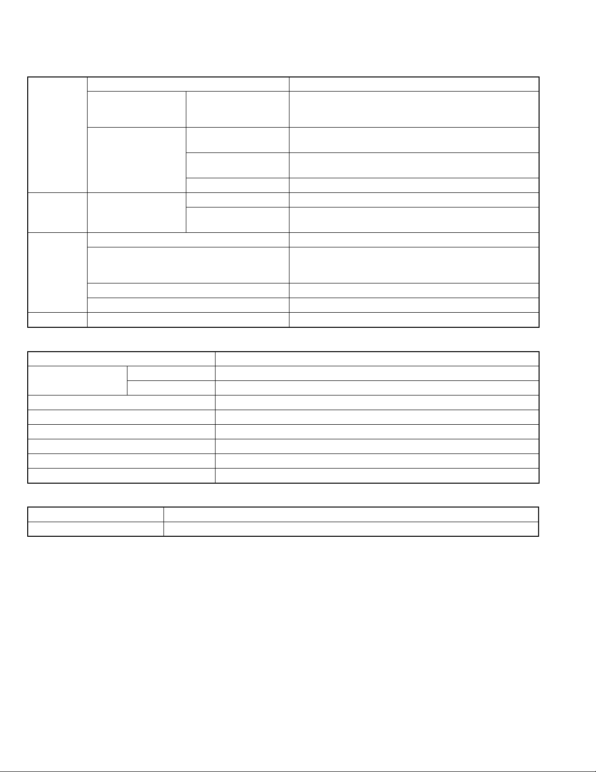
• Alternate check method
Plug the AC line cord directly into the AC outlet. Use an
AC voltmeter having, 1,000
in the following manner. Connect a 1,500
paralleled by a 0.15
exposed metal part and a known good earth ground.
Measure the AC voltage across the resistor with the AC
Ω per volt or more sensitivity
Ω 10W resistor
µF AC-type capacitor between an
voltmeter.
Move the resistor connection to each exposed metal
part, particularly any exposed metal part having a return
path to the chassis, and measure the AC voltage across
the resistor. Now, reverse the plug in the AC outlet and
repeat each measurement. Voltage measured any must
not exceed 0.75 V AC (r.m.s.). This corresponds to 0.5
mA AC (r.m.s.).
AC VOLTMETER
(Having 1000
ohms/volts,
or more sensitivity)
0.15 F AC TYPE
Place this
probe on
1500 10W
Good earth ground
1.2 Warning
(1) This equipment has been designed and manufactured to
meet international safety standards.
(2) It is the legal responsibility of the repairer to ensure that
these safety standards are maintained.
(3) Repairs must be made in accordance with the relevant
safety standards.
(4) It is essential that safety critical components are replaced
by approved parts.
(5) If mains voltage selector is provided, check setting for local
voltage.
1.3 Caution
Burrs formed during molding may be left over on some parts
of the chassis.
Therefore, pay attention to such burrs in the case of preforming repair of this system.
1.4 Critical parts for safety
In regard with component parts appearing on the silk-screen
printed side (parts side) of the PWB diagrams, the parts that are
printed over with black such as the resistor ( ), diode ( )
and ICP ( ) or identified by the " " mark nearby are critical
for safety. When replacing them, be sure to use the parts of the
same type and rating as specified by the manufacturer.
(This regulation dose not Except the J and C version)
each exposed
metal part.
(No.MB574)1-3
Page 4
1.5 Preventing static electricity
Electrostatic discharge (ESD), which occurs when static electricity stored in the body, fabric, etc. is discharged, can destroy the laser
diode in the traverse unit (optical pickup). Take care to prevent this when performing repairs.
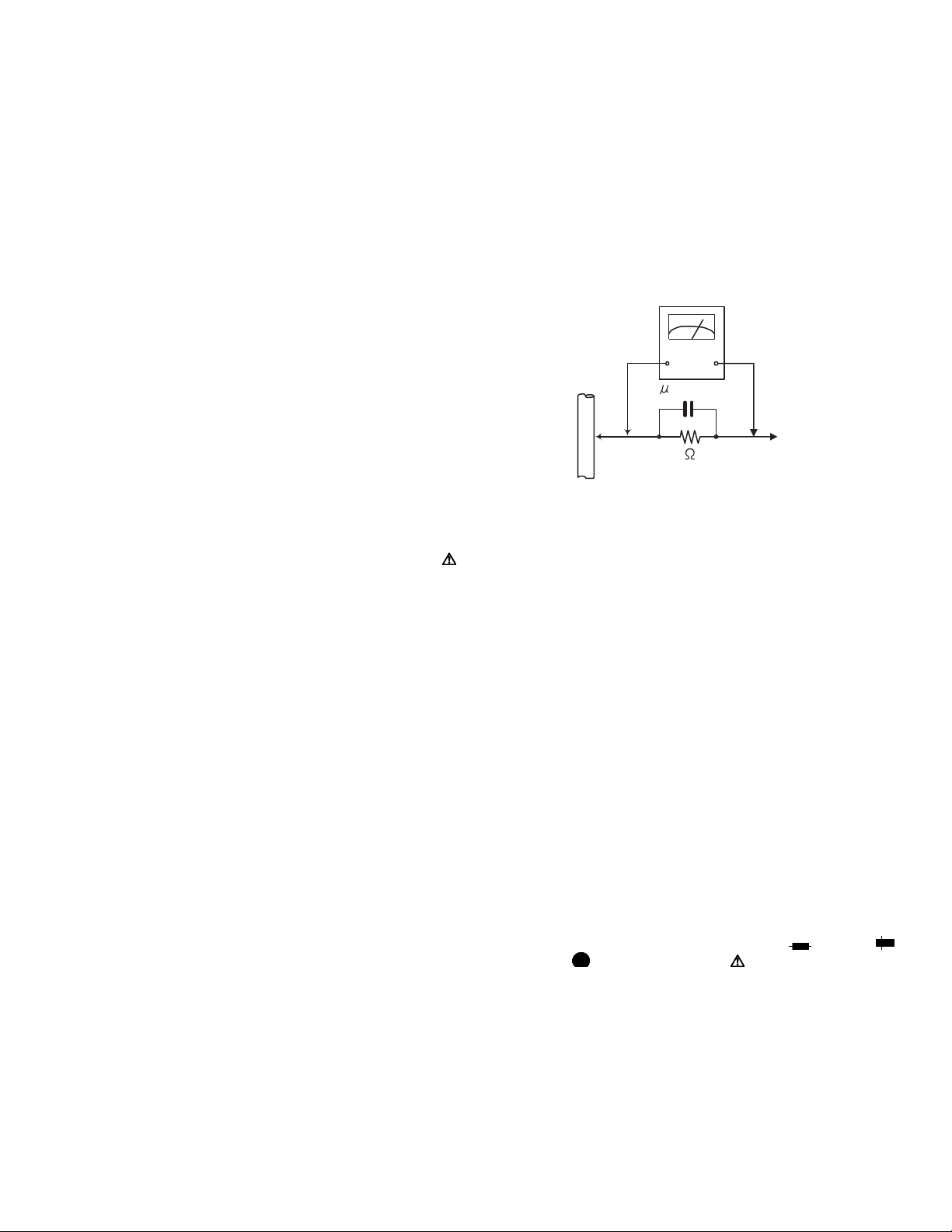
1.5.1 Grounding to prevent damage by static electricity
Static electricity in the work area can destroy the optical pickup (laser diode) in devices such as laser products.
Be careful to use proper grounding in the area where repairs are being performed.
(1) Ground the workbench
Ground the workbench by laying conductive material (such as a conductive sheet) or an iron plate over it before placing the
traverse unit (optical pickup) on it.
(2) Ground yourself
Use an anti-static wrist strap to release any static electricity built up in your body.
(caption)
Anti-static wrist strap
1M
Conductive material
(conductive sheet) or iron palate
(3) Handling the optical pickup
• In order to maintain quality during transport and before installation, both sides of the laser diode on the replacement optical
pickup are shorted. After replacement, return the shorted parts to their original condition.
(Refer to the text.)
• Do not use a tester to check the condition of the laser diode in the optical pickup. The tester's internal power source can easily
destroy the laser diode.
1.6 Handling the traverse unit (optical pickup)
(1) Do not subject the traverse unit (optical pickup) to strong shocks, as it is a sensitive, complex unit.
(2) Cut off the shorted part of the flexible cable using nippers, etc. after replacing the optical pickup. For specific details, refer to the
replacement procedure in the text. Remove the anti-static pin when replacing the traverse unit. Be careful not to take too long a
time when attaching it to the connector.
(3) Handle the flexible cable carefully as it may break when subjected to strong force.
(4) I t is not possible to adjust the semi-fixed resistor that adjusts the laser power. Do not turn it.
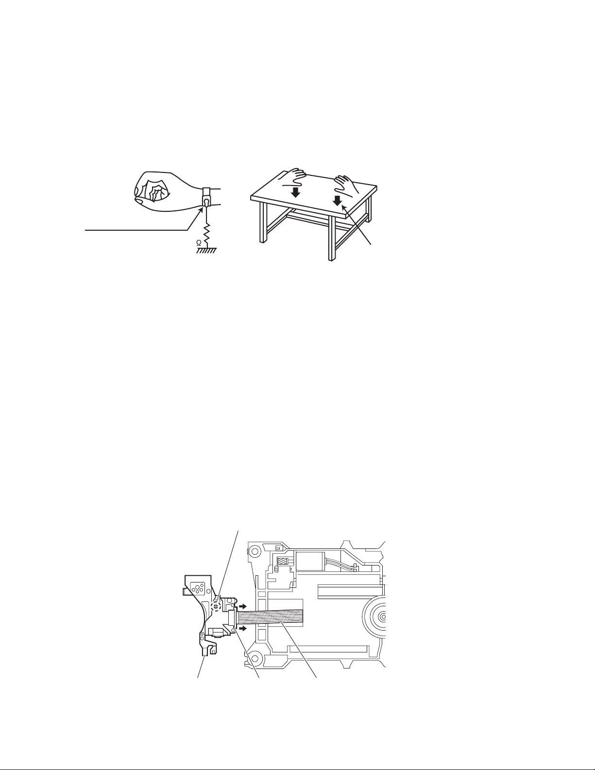
1.7 Attention when traverse unit is decomposed
*Please refer to "Disassembly method" in the text for the pickup unit.
• Apply solder to the short land sections before the card wire is disconnected from the connecto on the servo board. (If the card wire
is disconnected without applying solder, the pickup may be destroyed by static electricity.)
• In the assembly, be sure to remove solder from the short land sections after connecting the card wire.
1-4 (No.MB574)
Short land section
Pickup Connector Card wire
Page 5
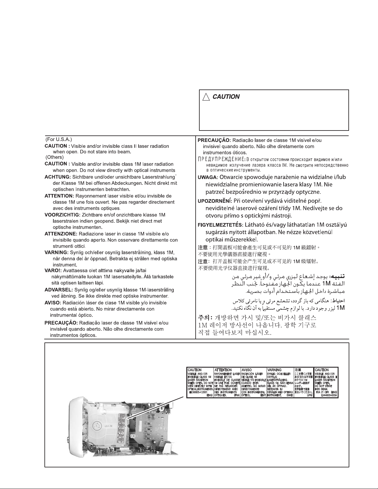
1.8 Important for laser products
1.CLASS 1 LASER PRODUCT
2.CAUTION :
(For U.S.A.) Visible and/or invisible class II laser radiation
when open. Do not stare into beam.
(Others) Visible and/or invisible class 1M laser radiation
when open. Do not view directly with optical instruments.
3.CAUTION : Visible and/or invisible laser radiation when
open and inter lock failed or defeated. Avoid direct
exposure to beam.
4.CAUTION : This laser product uses visible and/or invisible
laser radiation and is equipped with safety switches which
prevent emission of radiation when the drawer is open and
the safety interlocks have failed or are defeated. It is
dangerous to defeat the safety switches.
5.CAUTION : If safety switches malfunction, the laser is able
to function.
6.CAUTION : Use of controls, adjustments or performance of
procedures other than those specified here in may result in
hazardous radiation exposure.
!
Please use enough caution not to
see the beam directly or touch it
in case of an adjustment or operation
check.
REPRODUCTION AND POSITION OF LABELS and PRINT
WARNING LABEL and PRINT
(No.MB574)1-5
Page 6

SECTION 2
SPECIFIC SERVICE INSTRUCTIONS
This service manual does not describe SPECIFIC SERVICE INSTRUCTIONS.
1-6 (No.MB574)
Page 7
SECTION 3
r
DISASSEMBLY
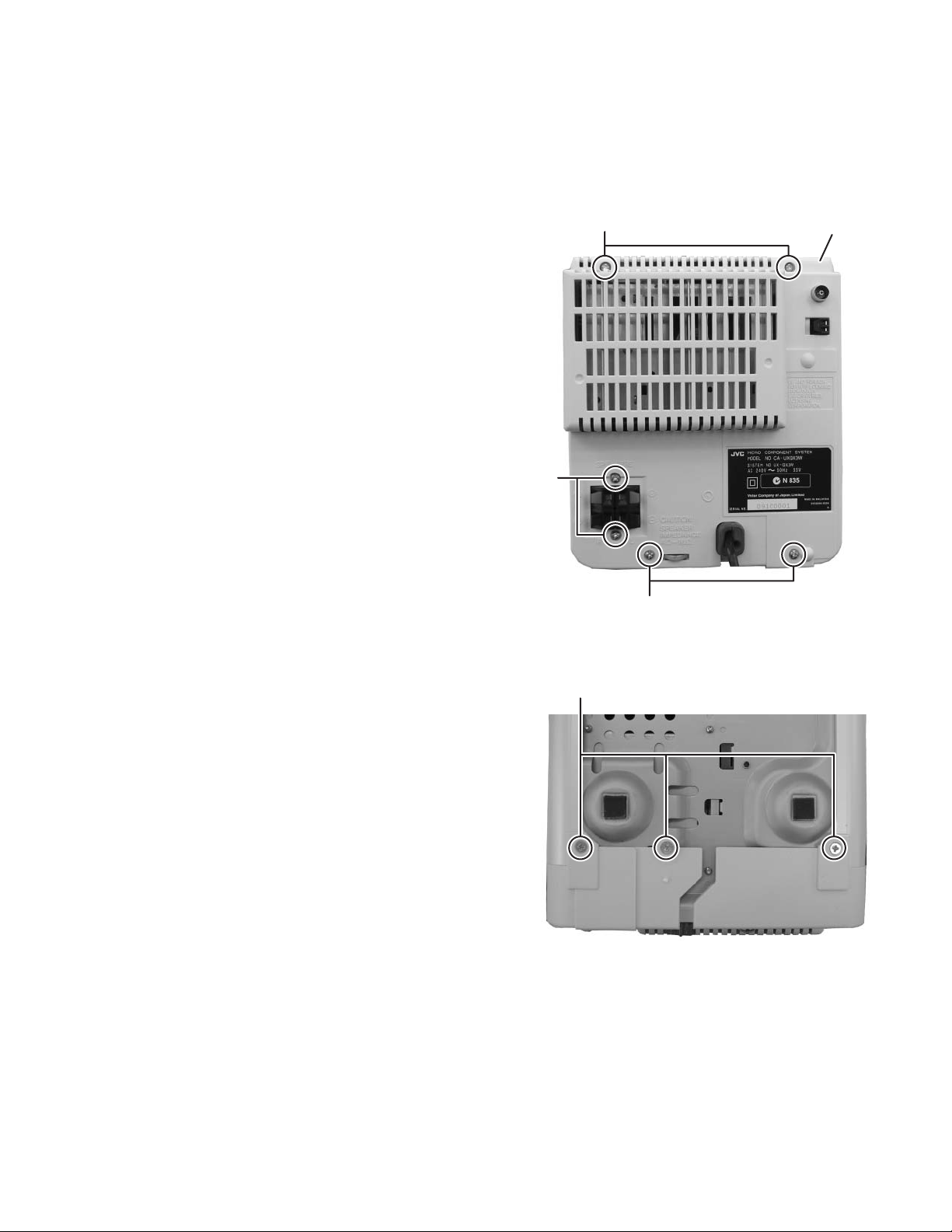
3.1 Main body
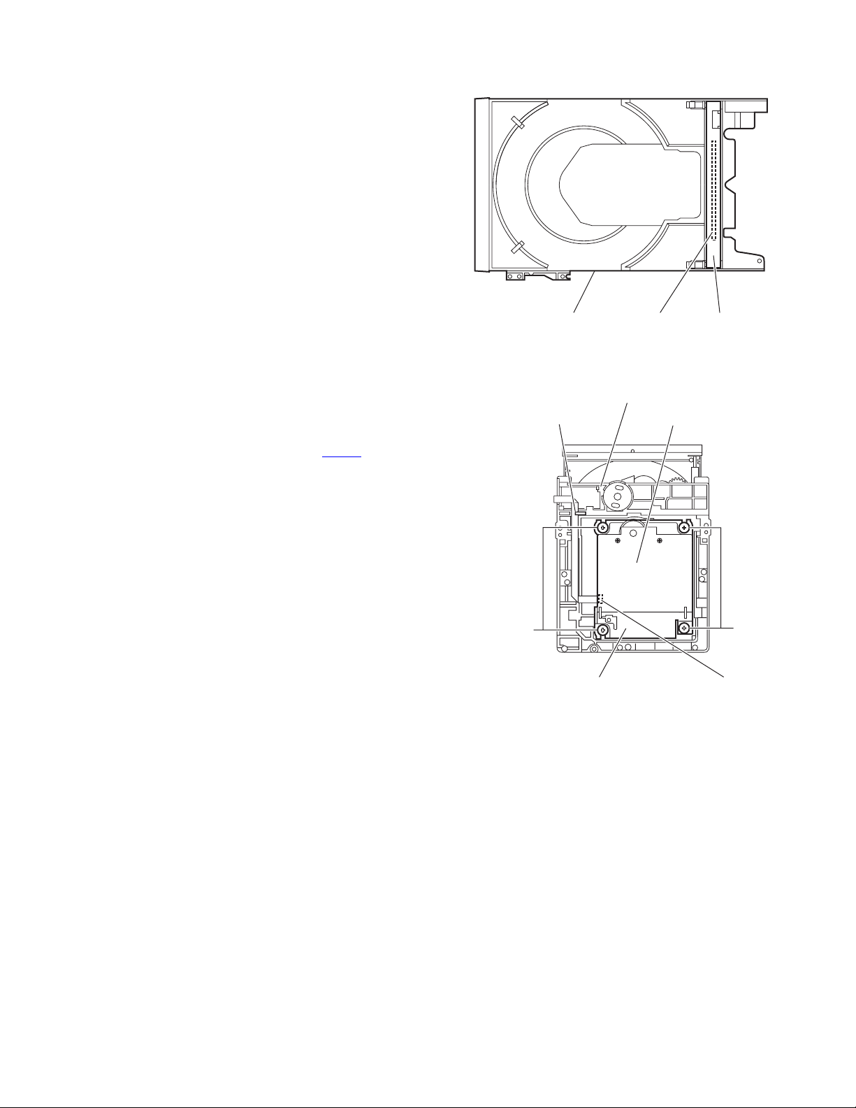
3.1.1 Removing the rear cover
(See Fig. 1, 2)
(1) Remove the six screws A attaching the rear cover. (See
Fig. 1)
(2) Remove the three screws B attaching the rear cover from
bottom side of main body. (See Fig. 2)
A
A
Rear cove
A
Fig.1
B
Fig.2
(No.MB574)1-7
Page 8
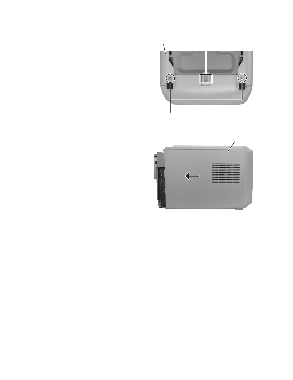
3.1.2 Removing the side panel
(See Fig. 3, 4)
(1) Remove the two screws C attaching the both side panels.
(See Fig. 3)
(2) Slide to backward and lift up then remove the both side
panels. (See Fig. 4)
Side panel
C
hook
Fig.3
c
Side panel
Fig.4
1-8 (No.MB574)
Page 9
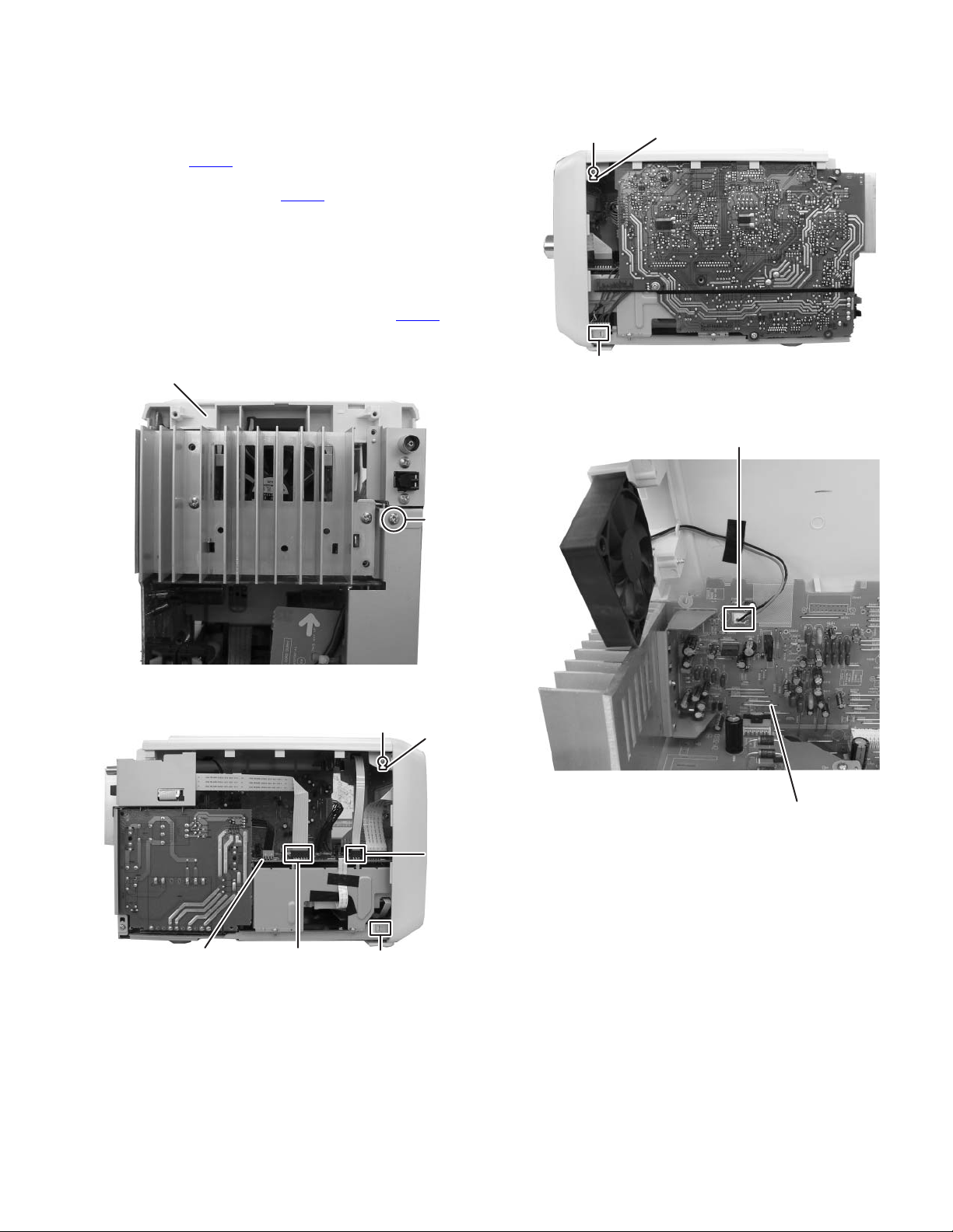
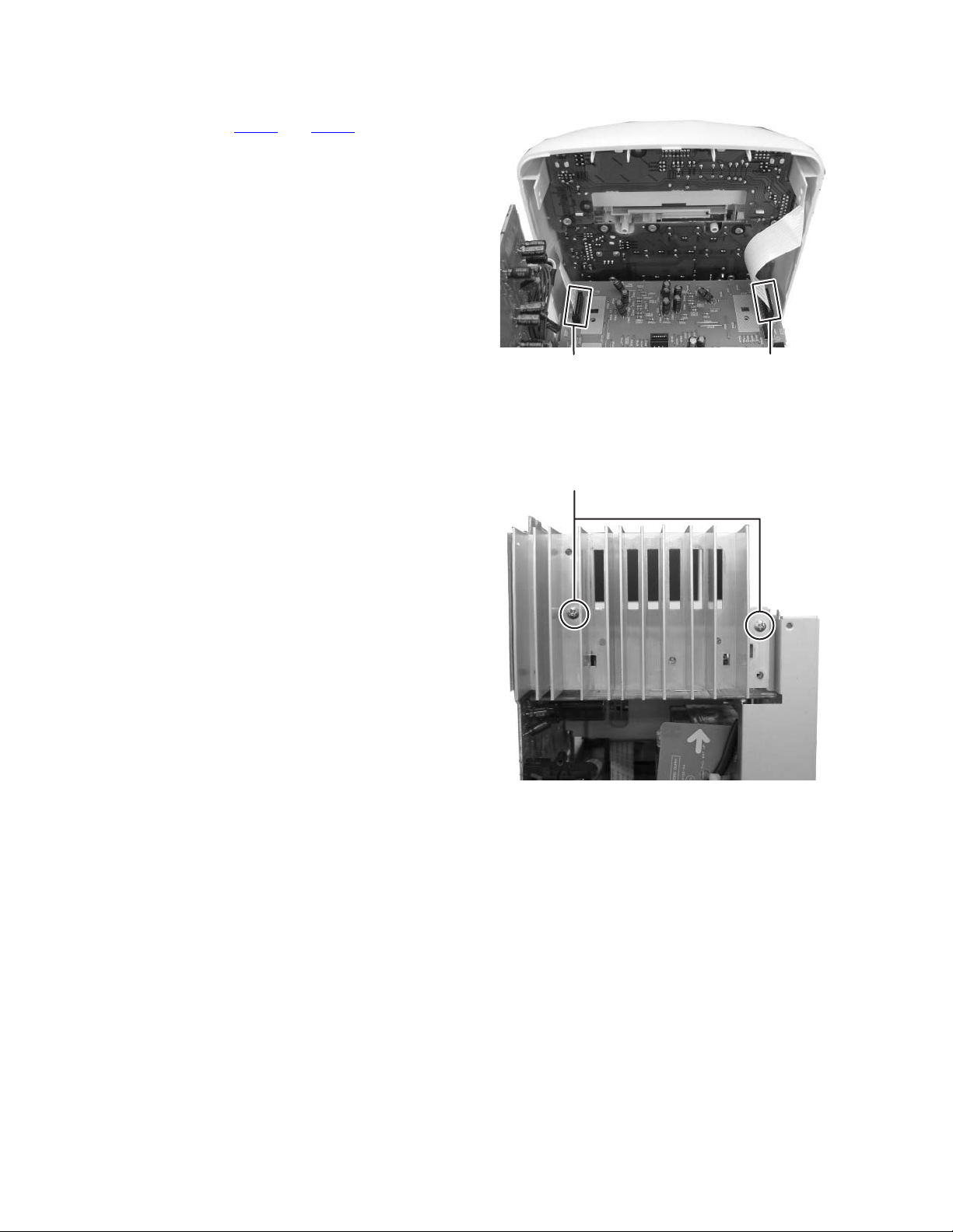
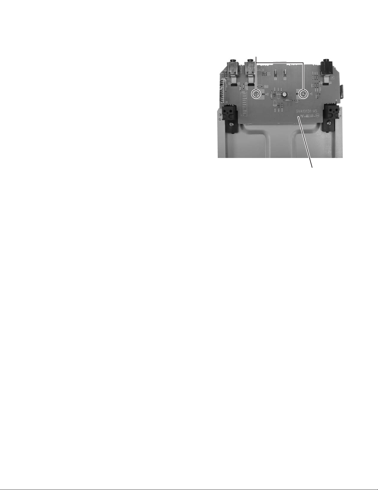
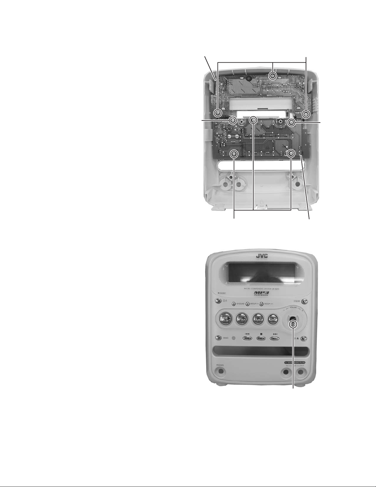
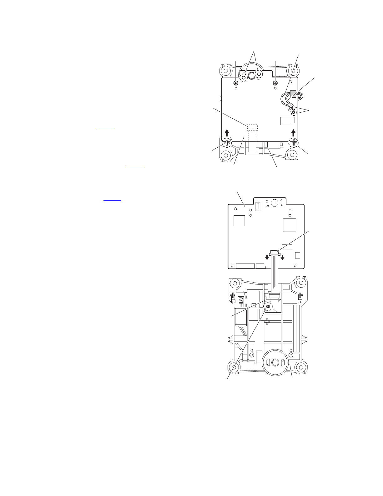
3.1.3 Removing the top cover
(See Fig. 5 to 8)
(1) Remove the one screw D attaching the tuner bracket. (See
Fig. 5)
(2) Disconnect the card wire from tuner pack connected the
connector CN709
(3) Disconnect the card wire from touch illumination board
connected the connector CN711
Fig. 6)
(4) Remove the two screws E attaching the top cover. (See
Fig.6, 7)
(5) Disengage the hook a and b form front panel assembly.
(See Fig. 6, 7)
(6) Lift up the top panel and then, disconnect the connector
wire from fan connected to the connector CN108
power amplifier board. (See Fig. 8)
of the micon board. (See Fig. 6)
of the micon board, (See
of the
E
hook
b
Top cover
Fig.5
E
D
hook
e
hook
Fig.7
CN108
a
Micon board
CN709
Fig.6
hook
d
CN711
Power amplifier board
Fig.8
(No.MB574)1-9
Page 10
3.1.4 Removing the front panel assembly
(See Fig. 9, 3, 6, 7)
(1) Disconnect the card wires from front panel assembly con-
nected to the connector CN702 and CN710 of the micon
board. (See Fig. 9)
(2) Disengage the hook c, d and e from the bottom chassis.
(See Fig. 3, 6 and 7)
3.1.5 Removing the heat sink
(See Fig. 10)
(1) Remove the two screws F attaching the heat sink.
CN710 CN702
Fig.9
F
1-10 (No.MB574)
Fig.10
Page 11
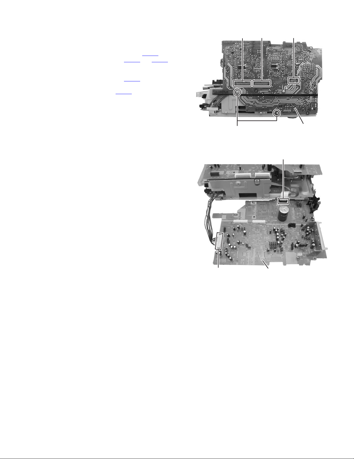
3.1.6 Removing the power amplifier board assembly
(See Fig. 11, 12)
(1) Remove the two screws G attaching the power amplifier
board assembly. (See Fig. 11)
(2) Disconnect the board to board connectors CN101
ed to secondary board assembly, CN102
nected to micon board assembly. (See Fig. 11)
(3) Disconnect the connector wire from head phone board as-
sembly connected to connector CN109
board assembly and disconnect the card wire from CD
board connected to connector CN106
er board. (See Fig. 12)
and CN103 con-
of the amplifier
of the power amplifi-
connect-
CN103 CN102 CN101
CN109
G
Fig.11
Power amplifier board
Fig.12
Power amplifier board
CN106
(No.MB574)1-11
Page 12
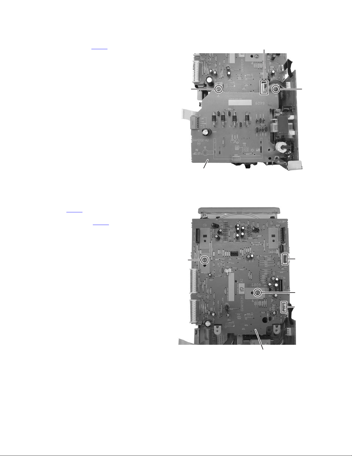
3.1.7 Removing the secondary board assembly
(See Fig. 13)
(1) Disconnect the connector wire from primary board assem-
bly connected to connector CN202 of the secondary board.
(2) Remove the two screws H attaching the secondary board
assembly.
3.1.8 Removing the micon board assembly
(See Fig. 14)
(1) Disconnect the card wire from the CD servo board connect-
ed to connector CN705
(2) Disconnect the connector wire from primary board assem-
bly connected to connector CN713
sembly.
(3) Remove the two screws J attaching the micon board as-
sembly.
of the micon board.
of the micon board as-
CN202
HH
Secondary board
Fig.13
J
CN705
J
CN713
Micon board
Fig.14
1-12 (No.MB574)
Page 13

3.1.9 Removing the primary board assembly with power transformer
(See Fig. 15)
(1) Remove the three screws K attaching the primary board
assembly with power transformer.
(2) Slide to direction of the arrow and then take out it.
KK
Fig.15
(No.MB574)1-13
Page 14
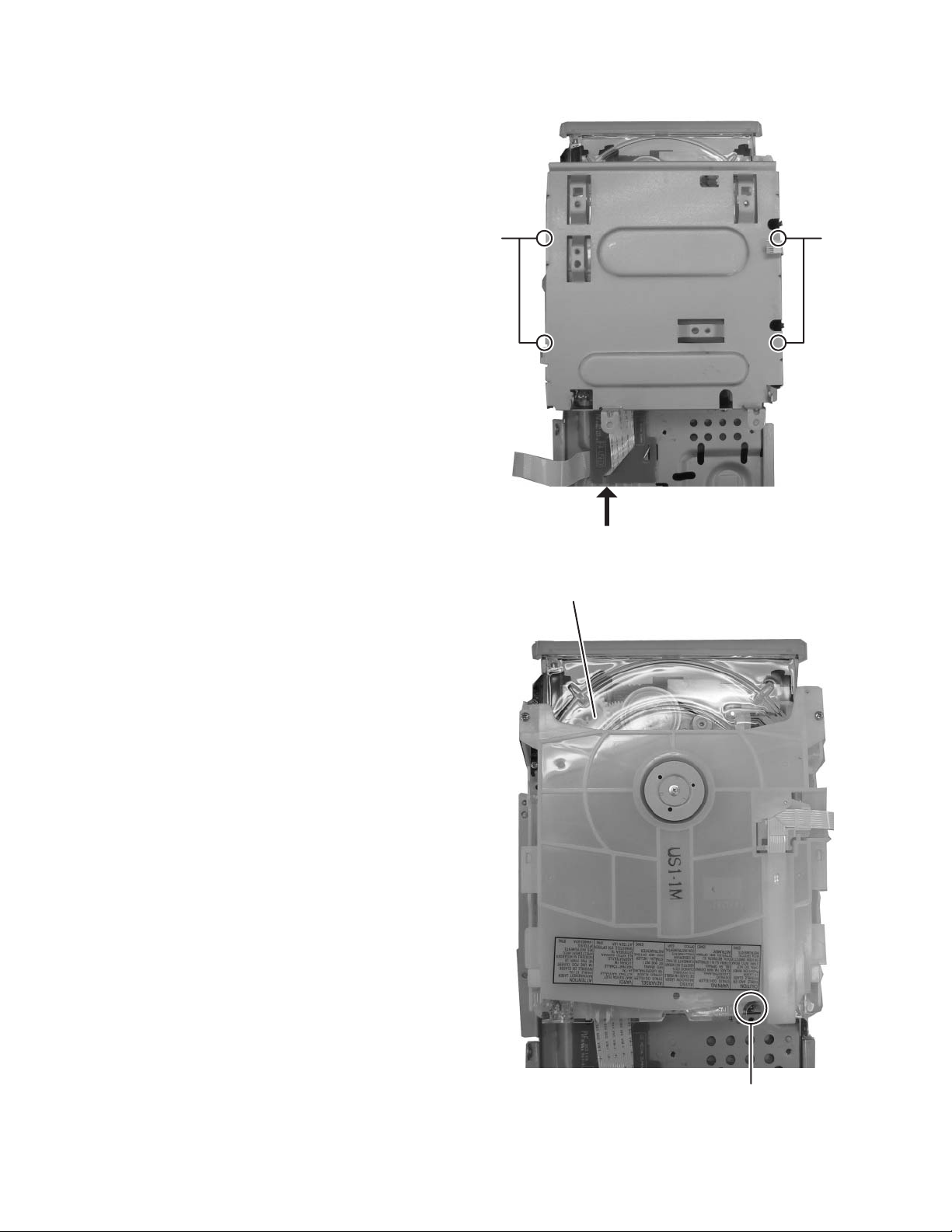
3.1.10 Removing the CD mechanism assembly
(See Fig.16, 17)
(1) Remove the four screws L attaching the CD mecha brack-
et. (See Fig. 16)
(2) Disengage the card wire from the CD board assembly en-
gaged to bracket board. (See Fig. 16)
(3) Remove the one screw M attaching the CD mechanism as-
sembly. (See Fig.17)
LL
CD mechanism assembly
Fig.16
1-14 (No.MB574)
M
Fig.17
Page 15
3.1.11 Removing the Headphone board assembly
(See Fig. 18)
(1) Remove the two screws N attaching the headphone jack
board assembly.
N
Head phone board
Fig.18
(No.MB574)1-15
Page 16
3.1.12 Removing the LCD board assembly
(See Fig. 19)
(1) Remove the three screws P attaching the LCD board as-
sembly.
3.1.13 Removing the key function board assembly
(See Fig. 19, 20)
(1) Remove the volume knob from front panel assembly.
(2) Remove the one screw Q attaching the key function board
assembly from front side. (See Fig. 20)
(3) Remove the five screws R attaching the key function board
assembly. (See Fig. 19)
LCD board
P
R
R
R
Key function board
Fig.19
1-16 (No.MB574)
Q
Fig.20
Page 17
3.2 CD mechanism assembly
• Remove the CD mechanism assembly from main body.
(Refer to "Disassembly method")
3.2.1 Removing the CD cover
(See fig.1 and 2)
(1) Remove the two screws A attaching the CD cover from top
side of CD mechanism assembly. (See fig.1)
(2) Remove the card wire from connector CN4
sembly. (See fig.1)
(3) Take out the CD cover.
Caution:
The spring which presses down a card wire is attached to CD
cover.
Please do not lose a spring. (See fig.2)
on the LED as-
A
CN4
A
CD cover
CD cover
Fig.1
Spring
Fig.2
LED assembly
(No.MB574)1-17
Page 18
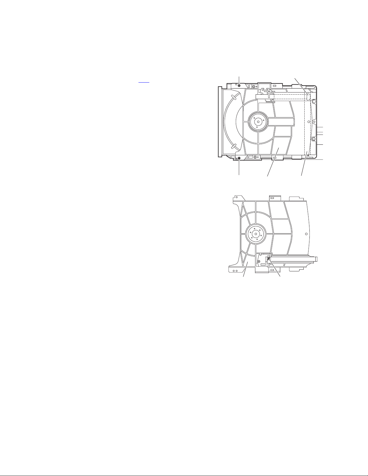
3.2.2 Removing the tray assembly
(See fig.3 and 4)
• Remove the CD cover.
(1) From the right-hand side of CD mechanism assembly, a
slide cam is pushed and a tray assembly is pulled out in the
direction of an arrow. (See fig.3)
(2) Remove the two screws B attaching the tray assembly
from top side of CD mechanism. (See fig.4)
(3) Remove the bushing of tray assembly from hook a of CD
mechanism assembly, and then take out the tray assembly. (See fig.4)
Tray assembly CD mechanism assembly
Slide cam
Fig.3
B
Hook a Hook a
Tray assembly
Fig.4
1-18 (No.MB574)
Page 19
3.2.3 Removing the LED assembly
(See fig.5)
• Remove the CD cover and tray assembly.
(1) Remove the double face tape attaching the LED assembly
from top side of tray assembly, and then take out the LED
assembly.
3.2.4 Removing the traverse mechanism assembly
(See fig.6)
• Remove the CD cover.
(1) Remove the four screws C attaching the traverse mecha-
nism assembly from bottom side of CD mechanism assembly.
(2) Remove the card wire from connector CN602
board, and then take out the traverse mechanism assembly and CD servo board together.
Reference:
When attach the traverse mechanism assembly, the wire
should through part b.
on CD servo
Tray assembly LED assemlbyDouble face tape
Fig.5
CD mechanism assembly
Slot b
CD servo board
C
Traverse mechanism assembly
Fig.6
C
CN602
(No.MB574)1-19
Page 20
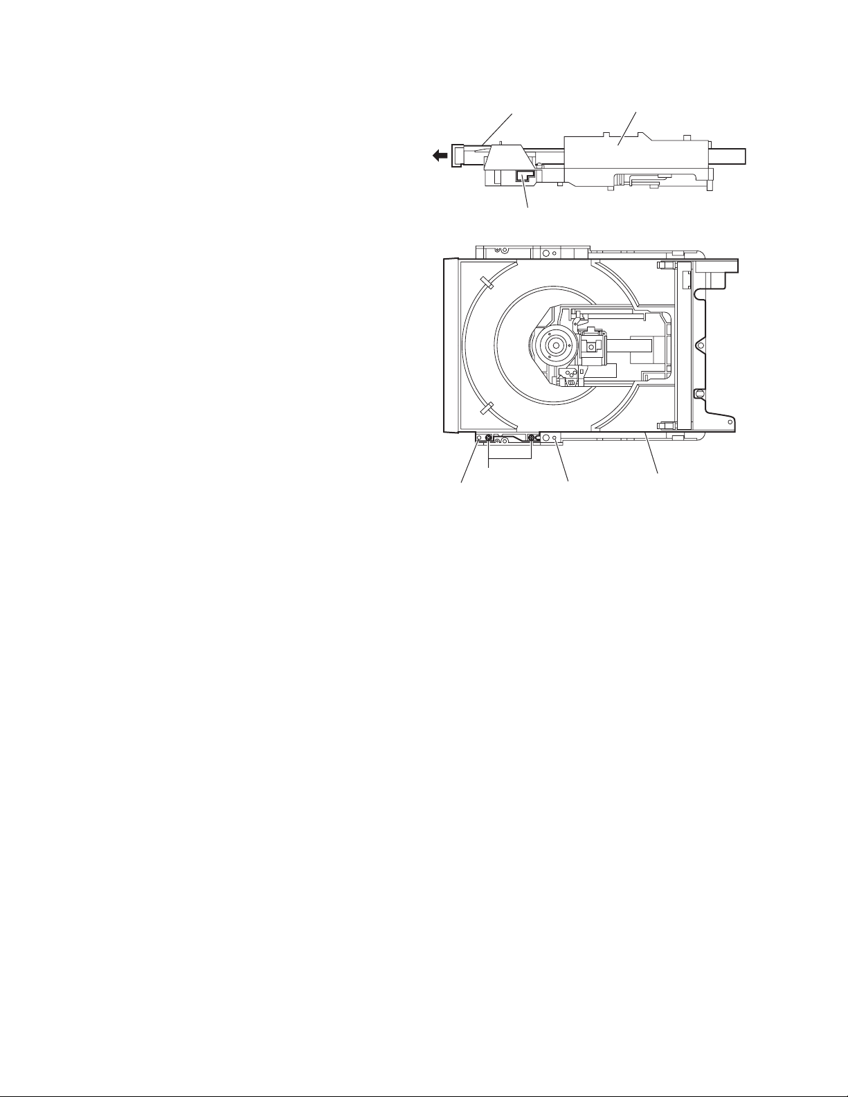
3.2.5 Removing the CD servo board
(See fig.7 and 8)
• Remove the CD cover and traverse mechanism assembly.
(1) Remove the two screws D attaching the CD servo board
from bottom side of traverse mechanism assembly. (See
fig.7)
(2) Remove the solder from soldered section c of CD servo
board. (See fig.7)
(3) Remove the yellow wire and white wire from soldered sec-
tion d of CD servo board. (See fig.7)
(4) CD servo board is removed upward, hook e is removed in
the direction 1 of an arrow, and CD servo board is turned
over. (See fig.7)
(5) Solder the short land section f of pickup. (See fig.8)
(6) The lock of the connector CN601
moved in the direction 2 of an arrow, and a card wire is re-
moved. (See fig.8)
Caution:
• Please solder the short land section f of a pickup before re-
moving a card wire from the connector CN601
board. If a card wire is removed without soldering, a pickup
may be destroyed by static electricity. (See fig.8)
• At the time of CD servo board attachment, please remove
the solder of the short land section f of a pickup after attaching a card wire in a connector CN601
of CD servo board is re-
of CD servo
. (See fig.8)
CN601
Hook e
Soldered section c
Wire(yellow)
DD
Wire(white)
Soldered
section d
11
Hook e
Travers mechanism assemblyCD servo board
Fig.7
CD servo board
Pickup
Short land section f
CN601
22
Traverse mechanism assembly
Fig.8
1-20 (No.MB574)
Page 21
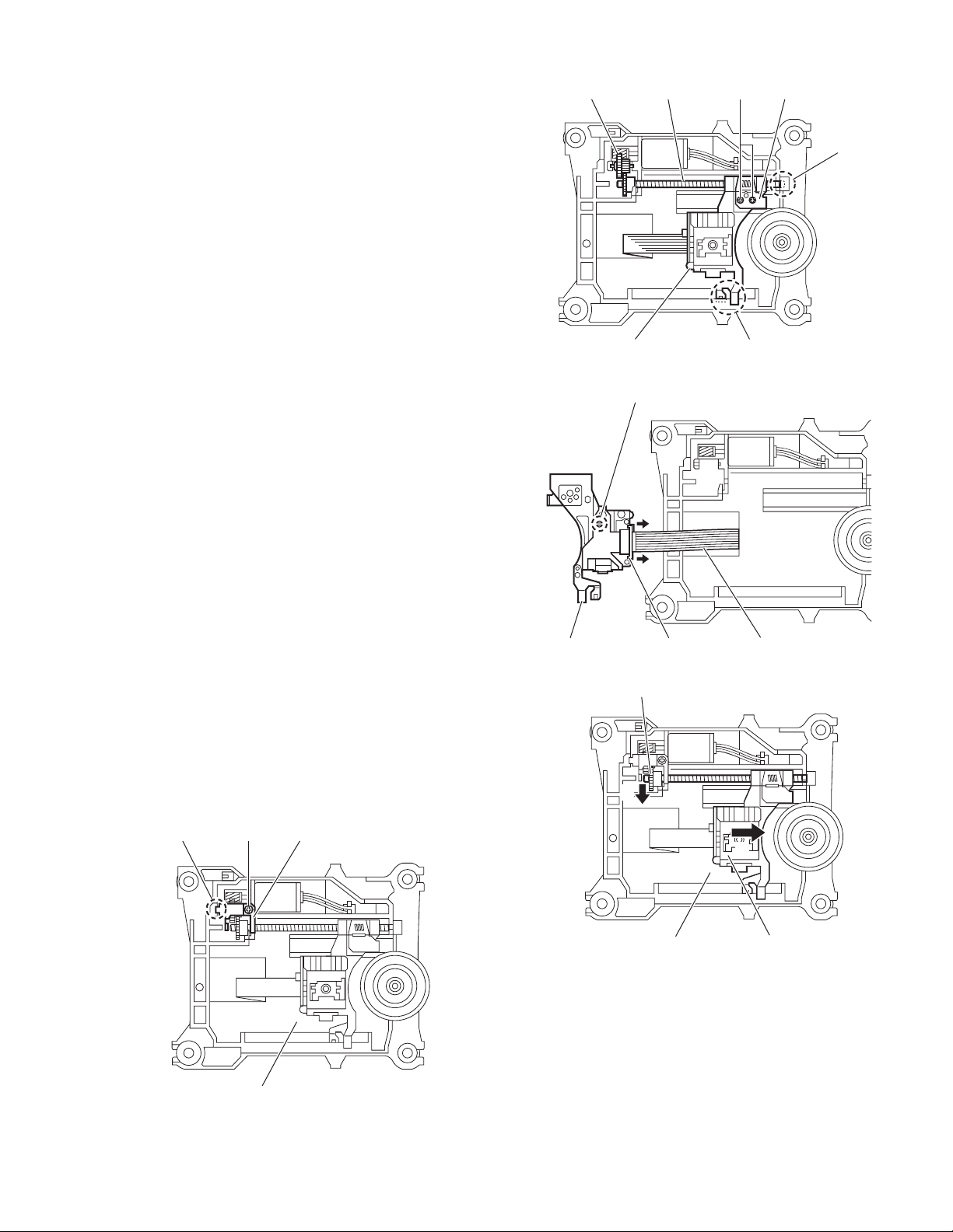
3.2.6 Removing the pickup
(See fig.9 to 11)
• Remove the CD cover and traverse mechanism assembly.
(1) Remove the screw E attaching the plate from top side of
traverse mechanism assembly. (See fig.9)
(2) Remove the plate from fixing part g, and then take out the
plate. (See fig.9)
(3) Remove the two screws F attaching the LAED spring. (See
fig.10)
(4) Take out the feed gear, and then remove the shaft of pick-
up from part h of traverse mechanism assembly. (See
fig.10)
(5) Remove the pickup from the part j of traverse mechanism
assembly, and then take out the pickup and shaft together.
(See fig.10)
(6) Draws out the shaft from pickup. (See fig.10)
(7) Solder the short land section k of pickup. (See fig.11)
(8) The lock of the connector of pickup is remover in the direc-
tion of an arrow, and a card wire is removed. (See fig.11)
Caution:
• Please solder the short land section of a pickup before re-
moving a card wire from the connector of pickup. If a card
wire is removed without soldering, a pickup may be destroyed by static electricity. (See fig.11)
• At the time of pickup attachment, please remove the solder
of the short land section k of a pickup after attaching a card
wire in a connector. (See fig.11)
Feed gear Shaft LEAD spring
Pickup
Short land section
F
j part
Fig.10
k
h part
3.2.7 Attaching the pickup
(See fig.9 to 12)
• Refer "Removing the pickup"
(1) After attaching a card wire in the connector of a pickup, the
solder of the short land section k of a pickup is removed.
(See fig.11)
(2) Attach the shaft to pickup. (See fig.10)
(3) A pickup is united with the part j of a traverse mechanism
assembly, and the end of the shaft of a pickup is attached
in the part h. (See fig.10)
(4) Attach the LEAD spring and feed gear. (See fig.10)
(5) Attach the plate. (See fig.9)
(6) A LEAD gear is turned in the direction 1 of an arrow, and
until full movement of the pickup is made to carry out in the
direction 2 of an arrow. (See fig 12)
Plate
EFixing point g
Pickup Connector Card wire
Fig.11
LEAD gear
1
2
Traverse mechanism assembly
Fig.12
Pickup
Traverse mechanism assembly
Fig.9
(No.MB574)1-21
Page 22

3.2.8 Removing the feed motor
(See fig.13 to 15)
• Remove the CD cover and traverse mechanism assembly.
(1) Remove the yellow wire and white wire from soldered sec-
tion m of the CD servo board at bottom side of traverse
mechanism assembly. (See fig.13)
(2) Remove the screw G attaching the plate, and the take out
the feed gear. (See fig.14 and 15)
(3) Remove the screw H attaching the feed motor, and then
take out the feed motor. (See fig.15)
Reference:
A time of feed motor attachment, the wire should through part
n of spindle base. (See fig.15)
G
Wire(yellow)
Wire(white)
Soldered
section m
Traverse mechanism assemblyCD servo board
Fig.13
Plate
Traverse mechanism assembly
Fig.14
H
Feed gear Feed motor
Traverse mechanism assembly
Fig.15
n part
1-22 (No.MB574)
Page 23

3.2.9 Removing the switch board
(See fig.6 and 16)
• Remove the CD cover.
(1) Remove the card wire from connector CN602
board from bottom side of CD mechanism assembly. (See
fig.6)
(2) Remove the wire from soldered section p of switch board.
(3) A switch board is raised pushing the hook q of CD mecha-
nism assembly in the direction of an arrow, and it removes
from the part r.
Reference:
• The wire should hook to part s after attached switch board
to CD mechanism assembly.
• Hook q of CD mechanism assembly should lock by glue.
3.2.10 Removing the motor
(See fig.16 and 17)
• Remove the CD cover and tray assembly.
(1) Remove the wire from soldered section p of switch board
from bottom side of CD mechanism assembly. (See fig.16)
(2) Remove the belt from motor pulley from top side of CD
mechanism assembly. (See fig.17)
Caution:
Be careful not to make grease adhere to a belt.
(3) Remove the two screws J attaching the motor to CD mech-
anism assembly, and then take out from bottom side of CD
mechanism assembly. (See fig.17)
Reference:
The wire should hook to part s after attached the motor to CD
mechanism. (See fig.16)
of switch
Switch board Wire
Soldered
section p
r part
s part
CD mechanism assembly
Hook q
CD mechanism assembly
Fig.16
BeltMotor pulley
J
Fig.17
(No.MB574)1-23
Page 24
SECTION 4
ADJUSTMENT
4.1 CD TEST MODE
4.1.1 Set the CD TEST MODE
Press STOP [ ] button and CD play/pause [ ] button together and keep then connect AC power cord.
LCD indication [ __CD_TEST_1].
Complete the setting TEST MODE.
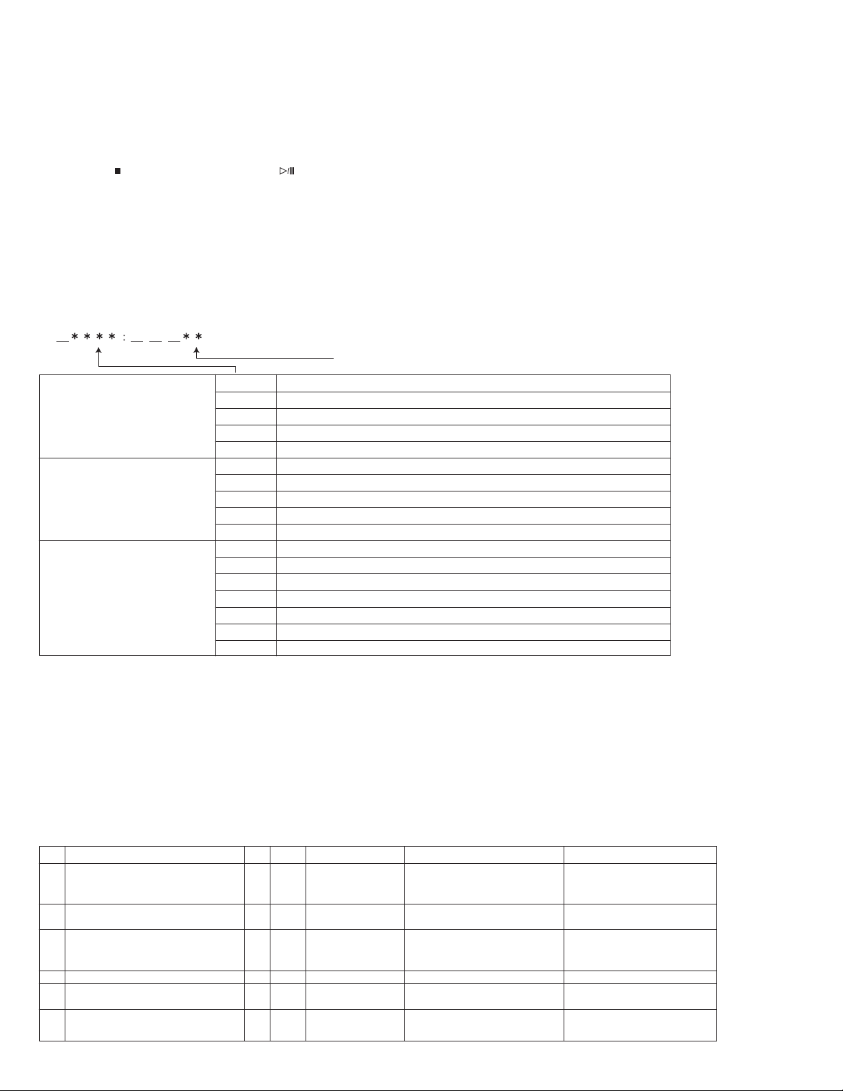
4.1.2 Set the CD TEST MODE 2 (Indication auto adjustment value)
At LCD indication [ __CD_TEST_1] condition, press [SET] key of the remote controller more than 3 sec.
LCD indication change to [ __CD_TEST_2].
Assumes after the TOC reading to be effective, and (E1 ~ E3) is transmittend in order in the table at each SET
reception of remote control.
The E1 status : the adjustment value (ten kinds) based on status with [1:OK,0:NG] of bit like the HEX data.
As follows at each reception
[ ] and the toggle are displayed.
Adjust value
Focus gain mantissa
Focus gain index part
Focus balance adjustment value
Focus offset adjustment value
Turbulence amplitude when focus gain is adjusted
Tracking gain mantissa
Tracking gain constant index part
Tracking balance adjustment value
Tracking offset adjustment value
Turbulence amplitude when tracking gain is adjusted
Tracking energy gain (Only ST1 :. )
Focus energy gain
Tracking balance
Focus balance
Tracking rough gain
Focus rough gain
Focus offset
E2 status
(FOCUS system self
adjustment information)
E3 status
(TRACKING system self
adjustment information)
E1 status
(self adjustment information)
FG_ _
FEXP
FBAL
FOFS
FES_
TG_ _
TEXP
TBAL
TOFS
TES_
TAGC
FAGC
ABC2
ABC1
AGC2
AGC1
AOC1
"CD test mode 2" is released by CANCEL key to remote control.
Shifts to "CD test mode 1" (The display is returned to "__CD_TEST_1").
Clearness of test mode
All the CD test modes are made clear by the thing that the POWER key is pushed.
4.2 ERROR HISTORY
4.2.1 Outline
EEPROM use 256byte, when an abnormal state is generated, the factor is written in EEPROM.
Worth of a history is left for each item 16 times.
ERROR HISTORY.
4.2.2 EEPROM writing
(1) EEPROM information
ITEM EEP address byte Count Value of writing Writing condition Guessed factor
No.
1
SAFETY Number
AD value
2
Timer playback start NG
factor
3
P.OFF timeout factor
4
CD
5
P.OFF factor
6
Other
0x100
0x110
0x120
0x150
0x160
0x1A0
0x1B0~
1
1
1
1
1
1
Safety abnormal
16
No. & AD value
16
Factor of failure
16
Factor of failure
16
Factor of failure
16
Factor of power off
16
When detectiong of SAFETY
error, writing SAFETY number
and AD value
Timer playback is not starting
Time out of power OFF process
Error with CD
When starting of power OFF
process
Power circuit failure.
Damege of card wire.
Missing key operation.
User operation.
Mechanical and module failure.
Damege of card wire.
Missing key operation.
Mechanical and pickup failure.
User operation.
1-24 (No.MB574)
Page 25
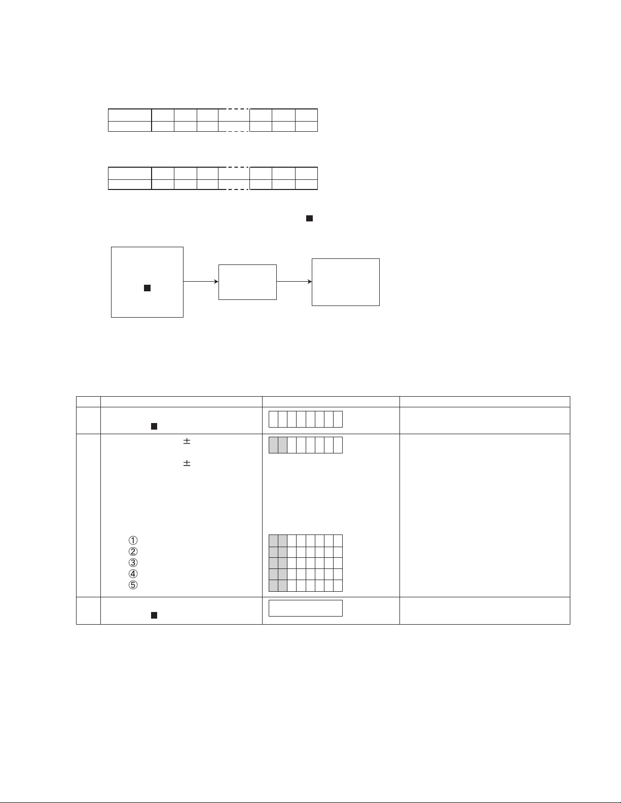
(2) EEPROM writing timing
When abnormality occurs respectively, the value of the generated item is rewritten.
at the following.
The writing method does the batch writing 16 bytes with PAGE WRITE.
exp.) The data taking to EEPROM
address
data
120 01121 02122
03
12D 0D12E 0E12F
0F
After it shifts in the direction of the subordinate position by one byte, "20" is written at head byte when ERROR
information new "20" is written. The data of final byte is thrown away.
address
data
(3) EEPROM clear condition
120 20121 01122
02
12D 0C12E 0D12F
0E
When COLD SET is fixed by remote control code [ 0 ]+[ ]+[STANDBY/ON] receive, the ERROR HISTORY part is
cleared (ALL0x00).
RECEIVE
[ 0 ]
+
[ ]
+
EEPROM
E.HISTORY
CLEAR
COLD SET
INDICATION
/
PROCESSING
[STANDBY/ON]
Do not clear EEPROM when COLD SET processing at power to ON.
In case of clear EEPROM, so that the ERROR HISTORY data may disappear when the set returned from the user.
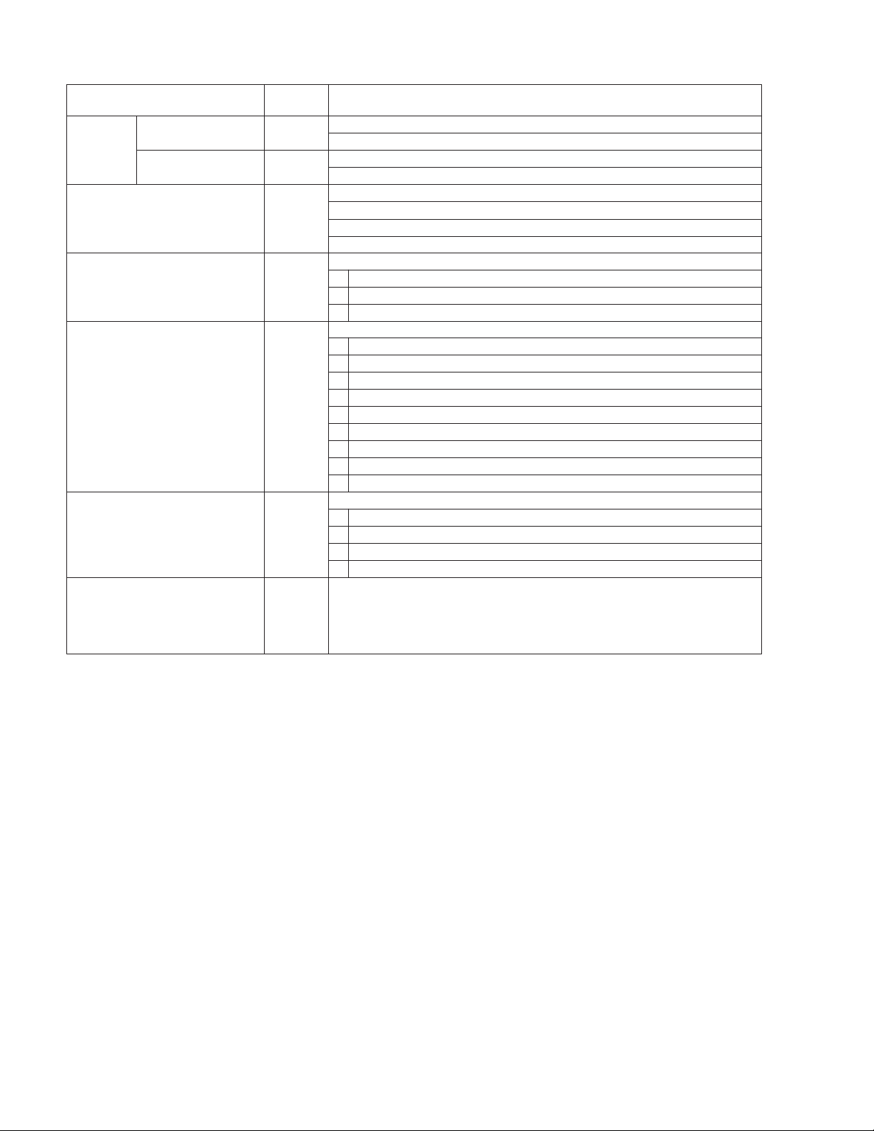
4.2.3 Reading the ERROR HISTORY
Reading ERROR HISTORY is assumed to be able to read set both POWER ON and turning off.
The reading method is done by the following ways.
No.
Operation Indication System micon processing
1 Receive the remocon code.
[COLOR]+[ ]+STANDBY/ON]
2 Address change to 0x01 by |<<, >>|
(skip) key of remote controller.
Address change to 0x10 by G|<<,
ERR I NFO
00 : 01
address data
Read out the ERROR HISTORY
information from EEPROM.
Indicate the read out value by key
operation.
G>>| (GROUP SKIP) key of remote
controller.
Indication is start address to 00 then
indicate staep by 1 byte.
operation exp.) address 00 indicating
Press >>| key
Press G>>| key
Press |<< key
Press G|<< key
Press G|<< key
3 Cancel the mode by remocon code.
01 : 05
10 : 21
0F: 11
00 : 01
F0 : 00
Return to normal function indication.
[COLOR]+[ ]+STANDBY/ON]
(No.MB574)1-25
Page 26
4.2.4 ERROR details
Item
SAFETY
Number
AD value
Timer playback start NG factor
P.OFF timeout factor 50
CD 60
P. O F F
OTHER
To p
address
00
10
20
A0
Low address and contents
SAFETY number at SAFETY occur.
1~5 (SAFETY watch umber difference by model)
AD value at SAFETY occur
00~FF
Factor that was not able to be playbacked at timer start of the playback.
10 CD NO DISC
11 CD OPEN
90 OTHER
Factor that was not able to be power off.
10 CD TIMEOUT
70 MECHA CLOSE TIMEOUT
90 OTHER
Abnormal factor concerning CD
31 SLED IN TIMEOUT SLED inside track shift timeout
32 SLED OUT TIMEOUT SLED outside track shift timeout
34 Q CODE 3s TIMEOUT Q code input 3sec timeout
35 TOC READ TIMEOUT TOC read timeout
36 SEARCH TIMEOUT Search timeout
3B FOCUS TIMEOUT Focus out ->[/FLOCK=H] detection
3C PLAY Q CODE ERROR Q Code continuous Error in Play
70 MECHA CLOSE TIMEOUT
71 MECHA OPEN TIMEOUT
Factor that was power off
10 NORMAL
20 AUTO STANDBY
30 SLEEP
40 TIMER
1-26 (No.MB574)
Page 27

SECTION 5
TROUBLESHOOTING
This service manual does not describe TROUBLESHOOTING.
(No.MB574)1-27
Page 28

Victor Company of Japan, Limited
Audio/Video Systems Category 10-1,1chome,Ohwatari-machi,Maebashi-city,371-8543,Japan
(No.MB574)
Printed in Japan
VPT
Page 29

SCHEMATIC DIAGRAMS
MICRO COMPONENT SYSTEM
UX-QX3WA,UX-QX3AA
CD-ROM No.SML200609
SP-UXQX1W
SP-UXQX1A
Lead free solder used in the board (material : Sn-Ag-Cu, melting point : 219 Centigrade)
Contents
Block diagrams
Standard schematic diagrams
Printed circuit boards
COPYRIGHT 2006 Victor Company of Japan, Limited.
CA-UXQX3W SP-UXQX1W
CA-UXQX3A SP-UXQX1A
2-1
2-2
2-7 to 9
No.MB574SCH
2006/9
Page 30

In regard with component parts appearing on the silk-screen printed side (parts side) of the PWB diagrams, the
parts that are printed over with black such as the resistor ( ), diode ( ) and ICP ( ) or identified by the " "
mark nearby are critical for safety.
Page 31

Block diagram
PICKUP
FOCUSING
COIL
TRACKING
COIL
LOADING
MOTOR
S1
TRAY
SWITCH
SW601
REST
SWITCH
FEED
MOTOR
M601
SPINDLE
MOTOR
CD servo control section
A+C, B+D, E, F
CN601 CN602
CN001
CN1
MD, LD
T+/-, F+/-
LD+/-
OPEN, CLOSE
REST
FM+/-
SM+/-
RF & SERVO
IC801
FOCUS, SPINDLE
FEED, TRACKING
LOADING BTL
DRIVER
IC601
AMP
TBAL, FBAL, FE, TE
GCTL, RFENV, OFT
BDO, ARF, /RFDET
TRD
FOD
FEED
SPINDLE
FWD
REV
DRMUTE
MON,
XTCK
TXTD
DQSY
/RST_DSP
STAT
BLKCK
MLD
MDATA
MCLK
FLAG
P.ON
IC251
UNIT
MICON
IC651
DSP
E2PSDA
E2PSCL
TXDO
RXDO
/RESET
X651
33.8688MHz
/DCAS
/DRAS
IC682
CASCNT
RASCNT
IC681
/DWE
WECNT
IC201
EEPROM
X251
8.38MHz
CD mecha LED section
LCDR, LCDG, LCDB
RCDR, RCDG, RCDB
D1,D2
LED
OUTL
OUTR
AD0 to AD10
D0 to D3
IC671
DRAM
/CAS
/RAS
/WE
CN4
CN651
System control section
CN705
QA781 to QA785
Q7801 to Q785
LCDR
LCDG
LDE DRIVER
LCDB
RCDR
RCDG
RCDB
IC741
E2CLK
E2DATA
EEPROM
Q7301,Q7311
BUP,RESET
IC401
Q4301 to Q4306
DETECTOR AMP.
BUP
RESET
Main amplifier section
CDCMD
CN106
CDSTAT
CDRESET
CDL/R
Q6151,Q6251
AHB
IC601
ALPHA SOUND
LOUT, ROUT
IC311
FUNCTION VOL.
CD5V
IC250
CD5V REG.
SW10V
IC240
SW10V REG.
S1+
CD8V
IC280
CD8V REG.
POUTSW10V
CLEDR
CLEDG
CLEDB
LLEDR
LLEDG
LLEDB
RLEDR
RLEDG
RLEDB
CN711
CN401
SENSOR1
AHB
PS1, PS2
MIXLEVEL
EXCTL
SOUNDCTL
OUTL2/R2
VOLCE
VOLCK
VOLDATA
TUL/R
LSELO, RSELO
AUXIL/R
FCD
VOLCE
VOLCK
VOLDATA
AHB
PS1
PS2
MIXLEVEL
EXCTL
SOUNDCTL
CN707
CN102
LLCR, LLCG, LLCB
RLCR, RLCG, RLCB
X7002
32.768kHz
IC701
X7001
MICON
CDCMD
CDSTAT
CDRESET
QPLINK
SMUTE
AUXMUTE
POUTAMP
POUTSW10
FCD
PROTECT
AUXSW
FANON
CN706 CN713
CN103
8MHz
REM, KEYP, FKEY1, FKEY2, JOGL/R
US6V
Q7901
to Q7903
US6V REG.
SUBTRDC
FTU
Q7351
to Q7353
TU9V REG.
SW10V
TU9V
Trans & Diode bridge section
CN101
CN201
FAN_ON
SMUTE
Q1103,Q1203
SYSTEM MUTE
Q3037
Q3038
FAN
DRIVE
Q1302
S1+
D2901
to D2904
DIODE
BRIDGE
CN108
FAN
MOTOR
POUTAMP
INL
INR
AUXMUTE
AUXOL/R
QPLINK
S1A
S1B
PROTECT
POWER
to Q3382
AUX MUTE
IC391,IC392
QP LINK
LCDSO, LCDSCL
LCDCSB, LCDRS
LCDXRESET
STANDBYLED
CVOR
CVOG
CVOB
TUCE
TUCLK
TUDATAI
TUDATAO
TUL/R
POUTRELAY
WR902
CN202
SUBTRDC
to D9005
BRIDGE
Q1101,Q1102
Q1201,Q1202
PROTECTOR
IC101
AMP.
Q3380
Q3190
D9002
DIODE
Q1301
+OUTL/R
AUXOL/R
AUXIN-L/R
LCD & LED section
CN702
CN531
STANDBYLED
LCDSO
LCDSCL
LCDCSB
LCDRS
LCDXRESET
LLCR, LLCG
LLCB, RLCR
RLCG, RLCB
Key & LED section
CN710
CN501
FKEY1
FKEY2
KEYP
CVOR
CVOG
CVOB
REM
JOGL/R
CN709
TUNER
UNIT
FW903
US6V
POUTRELAY
RY901
Q9001
RELAY
T9002
POWER
TRANS.
J1001
-OUTL/R
L+
SPEAKER
R+
WR601
CN109
AUXSW
Q5300,D5300
STANDBY LED
DI531
LCD DISPLAY
D5341,D5351
ILLUMI.
S5001 to S5013
KEY MATRIX
S5014
POWER SW
D5033
VOL ILLUMI.
IC501
REMOCON
JS501
VOLUME
S1A
S1B
T9001
POWER
TRANS.
CN901
L+, R+
+OUTL/R
AUXOL/R
AUXIL/R
AUXSW
J6000
J6001
J6030
AC IN
HEAD
PHONE
AUX
OUT
AUX
IN
2-1
Page 32

Standard schematic diagrams
Transformer and Rectifiers section
GVA10132-B2
S1GND
1
S1+
2
S2GND
S2REGGND
MD5.4VREG
POUTMD
of CN101
3
4
5
6
3.5V
TO GVA10132-B1
QGB2510K2-06
0V
19.8V
0V
0V
5V
CN201
MD5.4V REG.
Q2601
GVA10131-B1
C2906 1000/25
!
!
D2911
1N4003S-T5
D2912
1N4003S-T5
D2903
1N5402M-20
D2904
1N5402M-20
0.01/50
C2907
C2901
0.01/50
D2902
1N5402M-20
D2901
1N5402M-20
D2913
!
!
D2910
1N4003S-T5
1N4003S-T5
NI
NI
C2902
C2903
C2904
C2905
0.1/50
0.1/50
NI
NI
!
of CN201
of WR902
TO GVA10131-B1
1
9.2V
2
!
3
4
CN202
QGA2536C1-04
9.3V
6.5V
6.5V
TO GVA10132-B2
S1A
1
S1B
2
S2A
3
4
S2B
WR902
QJK008-040504-E
FT932
F9002
FT931
NI
1SS133-T2
NI
D9001
NI
NI
US6V
POUTRELAY
DG
SUBTRDC
CN713
FW903
QUM154-06DGZ4-E
5.8V
1
0.7V
2
0V
3
10.6V
4
0.7V
0.1V
0V
Q9001
KTC3875/YG/-X
C9002
330/25
1N4003S-T5
1N4003S-T5
1N4003S-T5
1N4003S-T5
D9005
D9002
C9003
D9004
0.01
D9003
61
7
8
9
11
13
14
QSK0124-001
12
T9002
*1
!
QQT0253-001
T9001
RY901
!
*1
7
B9004
6
5
4
2
!
34
4
B9005
100V
*1
*1
!
C9001
0.0047/250
!
B9902
41
LF901
QQR1321-001
B9901
!
NI
3
2
NI
F9001
FT911
CN901
QGA7901C1-02
!
*1
1
2
FT912
!
MAINS
PLUG
NIC2604
D2602
R2610
NI
R2606
R2603
D2601
NI
C2601
R2607
NI
NI
NI
R2605
NI
R2604
NI
C2603
NI
C2602
NI
R2608
NI
NI
0.6V
0.5V
0V
Q2604
NI
R2602
NI
Q2602
NI
NI
NI
NI
R2611
R2601
Q2603
NI
NI
R2612
TO GVA10132-A1 of
*1
A
UP
1,VOLTAGES ARE DC-MEASURED WITH A DIGITAL VOLT METER
NOTES
OR OSCILLOSCOPE WITHOUT INPUT SIGNAL.
CONDITION: CD STOP MODE/LED:RAINBOW/NO TAPE/AHB:ON/ALPHA SOUND:OFF
2.UNLESS OTHERWISE SPECIDIED.
ALL RESISTANCE VALUES ARE IN OHM(
T9001 B9005B9004Versions T9002AC(V) FREQ(Hz)
110
240
220
50
60
QQT0451-002 QQT0253-001
60
QQT0451-003
QQT0451-003
QQT0253-002 USE
QQT0253-003
NIUT
NI
NI
F9001 F9002
QMF51W2-1R6-J8USE
QMF51W2-R80-J8
QMF51W2-R80-J8
NI
NI
NIUSE
).
ALL CAPACITORS ARE CERAMIC CAPACITOR OR MYLAR CAPACITOR.
ALL CAPACITANCE VALUES ARE IN
ALL INDUCTANCE CALUES ARE IN
ALL E.CAPACITORS ARE SHOWN IN THE FORM
CAPACITANCE (
F)/RATED VOLTAGE (V).
3.NI MEANS NO INSERT
F(P=pF).
H(m=mH).
Parts are safety assurance parts.
When replacing those parts make
sure to use the specified one.
2-2
Page 33

Amplifier and Jack section
GVA10132-B1
CN107
FAN-ON
NI
1.4V
21
0V
20
C3161
1.4V
19
4.8V
18
C3266
1.6V
17
NI
5V
16
1.6V
15
0V
14
0V
13
0V
12
5V
11
0V
10
4.9V
9
4.7V
8
3V
7
6
4.4V
5
4.4V
4
4.4V
3
1.6V
2
4.4V
1
4.4V
1
0V
2
0V
3
0V
4
12V
5
0V
6
0V
7
0V
8
8.4V
9
4.9V
10
0V
11
0V
12
4.9V
13
0V
14
0V
15
0V
16
5V
17
0V
1
2.7V
2
4.3V
3
4
4.9V
5
1.6V
6
4.8V
7
4.8V
8
0V
9
0V
10
1.5V
11
0V
12
0V
13
1.5V
14
0V
15
0V
16
7.8V
17
7.8V
QGA2501C1-02
CN108
1
MGND
2
R3364
CN105
QGF1205F2-17
CN106
QGF1036C2-17
C3200
100/10
LEDGND
NI
C3166
L3363
NI
R3362
R3365
NI
100R3251
100R3151
PBMUTE
RECB
RECMUTE
A/B
SOL1
MOTOR
KEY
ENDSW1
L3321
(B1505)
BUS
K3321
(B1501)
BUS
K3324
(B1502)
BUS
K3323
(B1504)
TUL
DGND
AGND
TUR
0V
ACM-S2-1M CN100
TO CD MECHA
*
PART A VERSION
1. C3104, C3204
2. TAPE SECTION NO INSERT INSERT
4. D2700, D2701
C2701
FIGURE 1 (EMC C/M)
PART UP VERSION
1. C1110, C1210
2. C1111, C1211
3. C6006, C6008
4. C6012, C6014
5. PP300
0.033 u
0.033 u
0.01 u
680p
QNZ0104-001
RIN
AGND
LIN
A5V
ROUT
D5V
LOUT
DG
DOUT
DIN0
M5V
MGND
RESET
COMMAND
STATUS
COMCLK
STSRDY
DOUTOFF
DIN1
UART
MODESEL
RECR
MG
RECL
MB12V
PBR
AG
PBL
SW8V
PBMUTE
RECB
RMUTE
TO TAPE
A/B
SOL1
MOTOR
ACMSAFETY
KEY
ENDSW1
TXD0
RXD0
NC
/RESET
TX
3.3V
3.3V
DGND
DGND
OUTL
AGND
FMU-US1-1M
AGND
OUTR
MGND
MGND
+8V
+8V
TO FAN MOTOR
OTHERS
INSERTNO INSERT
INSERTNO INSERT3. IC270
INSERTNO INSERT
OTHERS
NO INSERT
NO INSERT
NO INSERT
NO INSERT
NO INSERT
AHB
C6322
D6301
100/16
MTZJ4.7C-T2
1k
R6306
68k
R6354
C6353
D6353
NI
R6019
C6014
FIGURE 1
C6004
27K
27K
300
300
300
0.01/50
1SS133-T2
J1001
QNB0181-002
1
2
3
4
5
300
1/4W
1/4W
1/4W
C6003
0.01/50
FIGURE 1
R6031
R6033
R+
L+
R-
L-
GND
1/4W
D6006
27K
27K
FIGURE 1
C6012
1SS133-T2
1SS133-T2
C6351
C6006
D6030
1SS133-T2
68k
R6352
1/50
TO SPEAKER
2
6
1
3
7
4
5
C6008
2
FIGURE 1
6
1
3
7
4
5
D6007
1SS133-T2
2
6
1
3
7
4
5
C6032
0.0022/50
HEAD PHONE
J6000
QNS0266-001
AUX OUT
J6001
QNS0266-001
TO CHASSIS GND
AUX IN
QNS0266-001
J6030
R6351
120k
R6353
NI
NI
C6352
NI
9.5V
9.5V
9.5V
9.5V
C1110
FIGURE 1
R6021
R6020
R6022
470
1/4W
470
1/4W
R6010
R6009
L6000
47
100/16
R6030
1K
C6031
100p
R6032
C6030
100p
R6034
D6031
0.0022
0.0039
C6311
C6309
4.4V
IC601 AN17140A-W
1.8V
R6302
0.47/50
R3384
5.2V
5.3V
R3385
C3380
22/50
CONNECT
TO SHIELD
R1102
C1103
10/25
9.6V
Q1102
KRA109S-X
0V
C6312 0.0015
4.4V
2.1V
47k
2.2K
2.2K
10k
9.6V
PS1
C6323
47/25
4.4V0V4.7V
0V
C6317 0.47/50
R3382
10K
R3383
10K
0V
0.7V
0V
0V
0.7V
0V
R1202
10k
R1101
9.6V
Q1202
KRA109S-X
1.8V
1.5k
R6251
R6259
9.6V
10k
C1203
10/25
9.6V
0V
MIXLEVEL
22
MIXLVL
C6251
NI
R6252
R3380
R3381
9.6V
KRA109S-X
9.6V
S2REGGND
MD5.4V
R6159 NI
C6151
1.5k
R6151
5.0V
C6256
0.47/50
2.7k
KTC3875/YG/-X
4.7K
4.7K
Q3380
2SC5938A/B/-X
Q3381
2SC5938A/B/-X
R1201
Q1201
S1GND
S1+
S2GND
Q6151
KTC3875/YG/-X
0V
0V
2.7k
0V
47k
12K
R6152
R6154
R6157
2k
2.2K
R6155
0.47/50
R6156
C6153
0.082
0.082
C6154
C6156
0.015
21
20
18
+INL19-INL
5.0V
4.7V
4.7V
OUTL1
4.7V
0.015
C6253
2.2K
R6255
R6254
0V
9.6V
9.6V
0V
9.6V
9.6V
0.5V
0V
0V
0V
0V
0V
10k
4.8V
OUTL2
4.4V
4.7V
4.8V
C6254
0.082
0.082
R6256
2K
12K
47k
R6257
C6316
100/25
0V
0V
Q6251
11
R+
11
+OUTR
10
10
HPGND
9
9
L+
8
8
+OUTL
7
7
AUXSW
6
6
AUXIR
5
5
4
4
3
3
AUXOR
2
2
1
1
CN109
WR601
QGA2536F1-11
WJP0084-002A-E
1
2
EP102
QNZ0136-001Z
3
1
W2
NI
0V
CN101
QGB2510J1-06
1
2
3
4
5
6
CN201
AUXIL
TO GVA10132-B2
IN GND OUT
20.5V
IC270
KIA7812API
123
0V
11.9V
C2701
47/25
AUXIR
GVA10131-B5
Parts are safety assurance parts.
When replacing those parts make
sure to use the specified one.
C6315
AUXIL
AUXGND
AUXOL
AUXSW
R6158
10k
330/10
R6301
100
C6155
10/50
R6153
200k
17
VCC
8.6V
0V
GND15VREF14OUTR213INR12+INR11OUTR110LFO39EXTCTL8LFO27LFO16PSC257IN46IN35OUT2OUTR1INR
16
R6253
200k
C6255
10/50
(B1506)
D6351
BUS
D6352
R6258
10k
C1111
C1210
C1211
FIGURE 1
FIGURE 1
FIGURE 1
NI
NI
11EQS03L-T4
11EQS03L-T4
D6003
D6001
D6002
D6000
C6001
B6031
QUY150-050Y
L6031
NI
L6030
NI
B6030
QUY150-050Y
PS2
0V
2.2
R1208
1/4W
C1206
SW10V REG.
KIA278R10PI-U/P
IN OUT GND CTRL
1234
9.6V
0V
2.2
0.1/50
IC240
10.1V
F)/RATED VOLTAGE(V).
EXCTL
0V
C6313
22/50
SOUNDCTL
R6304
Q6301
KTC3875/YG/-X
10k
0V
0V
0.001
R3106
1k
32
INL
3.8V
0.0056
C6305
C6302 0.027
C6307 0.0039
C6301
C6303 0.0033
31
OUTL301IN1292IN1282IN2273IN1263IN2253IN3244IN123PSC1
4.4V
4.4V
4.4V
4.4V
4.4V
SOUND IC
4.3V
4.0V
4.4V
3.7V
4.4V
3.8V
R3206
1k
10k
R6308
R6309
0V
0V
D1101
9.6V
20.6V
VCC13-OUTR12GND11+OUTR10GND9-OUTL8+OUTL7POP6INL5PP4STB3SG2RF1INR
14
36k
R1105
4.7/50
2.2
C1104
R1207
1/4W
7.5k
R1106
0.056/16C1105
0.1/50
C1207
!
C1303
8200/25
POUTSW10V
0V
5.2V
C2401
220/35R2402
10k
0V
Q6304
KTC3875/YG/-X
1SS133-T2
R1205
C1204
0.056/16C1205
!
C6320
0.0068
R6303
11k
C6321
C6319
0.012
10/50
D1201
1SS133-T2
36k
4.7/50
0.47/50C1305
7.5k
R1206
PROTECTOR
Q1301
KRC109S-X
NID1102
PROTECT
NIC1301
NID1202
*
D2701
C6318
KTA1504/YG/-X
Q3382
4.6V
R3386
5.6K
AUXMUTE
AUXSW
AUXIN-R
AUXIN-L
PP300
FIGURE 1
C1311
0.01
9.6V
0V
Q1101
KRA109S-X
POUTMD
A VERSION NI ONLY
TAPE 12V
D2700
1SS133-T2
MTZJ15B-T2
QPLINK
2.2/50
C3191
C3194
R3194
4.7K
4.6V
9.1V
4.6V
4.6V
8765
4.7K
R3191
+VCC
OUT2
-IN2
+IN2
IC391
KIA4558F-X
4.7K
R3291
OUT1
+IN1
-IN1
-VCC
4321
R3154
R3153
101112131415161718192021222324
5.2V
POUTPAMP
NIL3361
SAFETY
R3369
NIL3362
8.2k
12K
R3368
5.1K
10K
AUXMUTE
4.8V
4.6V
4.6V
4.6V
4.6V
NI
NI
C3163
C3263
8.2k
R3254
R3256
Q3300
KRC111S-X
C3037
FCD
POUTSW10V
POUTMD
3.7V
5.2V
5.2V
TO MICON BOARD
0V
R3294
4.7K
NI
C3362
NI
NI
FAN
PROTECT
0V
C3193
47/25
NI
1/4W
R3374
NIC3261
NI
NIR3363
NI
BUS
BUS
NI
R3262
R3162
NI
NI
W1
NI
8.2K
R3152
R3370
5.1K
10K
R3371
L3322
(B1503)
SW10V
CDRESET
SW10V
CDCMD
QPLINK
US5.4V
5.3V0V3.8V0V3.8V
SAFETYREG1
CDSTATO
10V
10V
5.1V
4.5V
2.8V
5.2V
CN103
QGB1218J1-24
FAN
CN706
2.2/50
1.3V
4.5V
9.1V
8765
100K
R3193
R3293
R3297
NI
D3392
3.3kR3255
3.3kR3155
NI
R3156
KRC111S-X
Q3301
1SS133-T2
D3037
AUXSW
SMUTE
123456789
0V
0.5V
4.5V
100K
B3017
100K
C3291
2.2/50
D3391
NI
Q3037
KTA1504/YG/-X
R3037
LEVELDET
0V
KEY
5.2V
C3297
10/50
NI
10K
Q3038
KRC102S-X
ENDSW1
KIA4558F-X
3.9V
D3297
R3295
1N4003S-T5
R3366
R3367
R3038
FAN DRIVE
SAFETY
MOTOR
0V0V0V
5.2V
+VCC
IC392
OUT1
R3264
R3164
1SS133-T2
10K
47K
SOL1
OUT2
-IN1
4.6V
220K
C3294
2.2/50
D3352
*
10K
A/B
+IN2
-IN2
+IN1
-VCC
4321
0V
4.6V
NI
NI
TAPE SECTION :
A VERSION NI ONLY
RECMUTE
5.1V
CN707
3.5V
R3263
NI
R3163
NI
1N4003S-T5
RECB
PBMUTE
QGB1218J1-22
QPLINK
Q3190
KRC109S-X
AUXIL
R3199
10K
R3195
10K
R3196
R3299
0
D3351
SIGN001400
EXCTL
SOUNDCTL
PS2
10111213141516171819202122
0V0V0V
0V0V0V
5V
CN102
R3197
100
0
C3199
47/25
NI
R3198
NI
R3298
AUXIR
MDR
MDL
MDRESET
MDCMD
MDSTAT
TAPER
TAPEL
DGND
D3393
1SS133-T2
CDL
CDR
VOLCE
VOLDATA
VOLCK
MIXLEVEL
PS1
AHB
MDRESET
MDCMD
MDSTAT
123456789
5.2V0V5.1V
3V
4.6V
KRC111S-X 10K
4.7V0V5.2V
AUXIN-R
AUXIN-L
47/25
C3500
R3500
R3400
4.7K
4.7K
22K
R3501
D3500
KDS4148U-X
C3401
47/25
R3402
120K
D3401
UDZW5.1B-X
VOLCK
VOLCE
VOLDATA
C3302
R3306
1/4W
330/10
R3302
2.2k
34
35
36
VDD
7.6V
5.2V
-
VOLCK
LOPOUT
FUNCTION VOL IC
VOLDATA2VOLCE3Vss4ROPOUT5RINM6RINP7ROUT8RSB9RBASS210RBASS111RTRE12RVRIN13RSELO14CDR15TAPER16MDR17TUNERR18AUXR
5.2V
0V
0.6V
1
R3303
2.2k
R3301
2.2k
B3010
R6951
NI
R1211
47/25
C3400
22K
R3401
D3400
KDS4148U-X
4.7k
R1111
4.7k
10KR1110
7.5k
R3105
R3104
180PC3113
180PC3112
-
BUS
Q6951
NI
C6952
NI
KTC2876-T
0.1
C3111
30
31
LSB
LOUT32LINP33LINM
3.8V
3.8V
IC311
LC75345M-X
3.8V
180PC3212
180PC3213
7.5k
R3205
RIPPLE FILTER
NI
0V
R1209
Q1203
0.8V
0V
KTC2876-T
0V
R1109
0.8V
1k
0V
100
-
-
C6951
10KR1210
Q1103
18k
7.5k
R3103
R3102
9.1k
0.1
0.0022
4.7/50C3108
C3109
C3110
C3107
0.0047
25
27
28
LTRE
3.8V-3.8V
3.8V
3.8V
LBASS129LBASS2
3.8V
3.8V
3.8V
3.8V
0.1C3210
0.0022
0.1C3211
C3209
R3203
7.5k
R3204
!
IC101
LA4628
C1209
10/50
C1109
10/50
Q1302
KTA1504/YG/-X
5.3V
5.1V
1k
4.6V
C1310
R1302
22/50
FAN CONTROL
!
IC250
KIA78R33API-U/P
IN
OUT
GND
CTRL
1234
7.9V
3.3V
5.2V
0V
C2502
D2500
1SS133-T2
LEVELDET
Q2403
0.6V
KRC102S-X
R1
R1
5.2V
10K
R2403
NI
0V
R1
R2
R1 R2
KRC102S-X 10K 10K
KRC109S-X 47K 22K
KRA109S-X 47K 22K
220/10
MTZJ5.1B-T2
D2501
SMUTE
FCD
NOTES
R1
R2
R1 R2
1.VOLTAGES ARE DC-MEASURED WITH A DIGITAL VOLT METER
2.UNLESS OTHERWISE SPECIFIED.
3.NI MEANS NO INSERT
MDL
CDL
TUL
TAPEL
AUXIL
10/50
C3105
470
4.7/50C3104
R3110
*
21
22
23
24
MDL
CDL
3.8V
3.8V
3.8V
3.8V
TAPEL
LSELO26LVRIN
3.8V
3.8V
3.8V
3.8V
470R3210
0.0047
C3207
4.7/50C3208
4.7/50C3204
R3202
C3205
10/50
*
9.1k
18k
4.7/50
MDR
C3206
CDR
TAPER
TUNERL
C3106
4.7/50
4.7/50
100/10
C3101
C3301
19
Vref20AUXL
3.8V
3.8V
3.8V
3.8V-3.8V 3.8V
4.7/50C3201
TUR
AUXIR
POWER AMP IC
0V
1.7V
9.4V
C1108
C1208
330P
330P
5.6k
C1309
100/25
1.7V
9.6V
3.3V
2.5V
NI
R1301
R1303 10k
NI
33/50
C1307
D1302
9.6V
2.1V
2.2
R1108
1/4W
R11071/4W
0.47/50C1306
C1107
C1106
0.1/50
0.1/50
CD8V REG.CD3.3V REG.
IC280
!
KIA78R08API
IN
OUT
GND
CTRL
1234
10.1V
0V
5.2V
7.9V
D2800
D2801
C2801
C2800
MTZJ9.1A-T2
100/16
NI
20.5V
C2400
100/35
D2401
D2400
MTZJ15B-T2
1SS133-T2
).
F(P=pF).
H(m=mH).
1SS133-T2
POUTPAMP
OR OSCILLOSCOPE WITHOUT INPUT SIGNAL.
CONDITION- CD STOP MODE/LED:RAINBOW/NO TAPE/AHB:ON/ALPHA SOUND:OFF
ALL RESISTANCE VALUES ARE IN OHM(
ALL CAPACITORS ARE CERAMIC CAPACITOR OR MYLAR CAPACITOR.
ALL CAPACITANCE VALUES ARE IN
ALL INDUCTANCE VALUES ARE IN
ALL E.CAPACITORS ARE SHOWN IN THE FORM OF CAPACITANCE(
2-3
Page 34

Micon, Key, Touch illumination and LCD section
RLCG
LCDG
LCDB
RCDB
LCDR
RCDR
LCDCSB
LCDRS
LCDSO
REM
JOGL
JOGR
KEYP
RLCR
RLCG
RLCB
LLCR
LLCG
LLCB
CVOR
CVOG
CVOB
R4309
470K
R4310
R4304
2.2M
15P
C4305
IC401
NJM4565M-WE
R4315
1M
2P
C4301
R7836
180
CVOB
R7843
180
CVOG
R7833
180
RLCB
R7808
180
R7829
180
LLCG
LLCB
CVOR
RLCR
LCDR
LLCR
22K
C4308
2P
4321
0V
GND
3.7V
-
+
+
-
4.8V
4.9V
R4316
220K
R4314
100K
680P
33P
C4307
C4311
C4304
R4311
2.2M
4.9V
GVA10131-B4
GVA10131-B3
39K
R5016
R5025
12K
6.8K
R5024
3.9K
R5023
2.7K
R5022
3.3K
R5021
VOL ILLUMI.
NSTM515AS
D5034
NI
D5036
NI
NI
D5035
KRC102S-X
KRC104S-X
KRA102S-X
KRA104S-X
KRC111S-X 10K
FKEY1
D5033
R1
D5341
R1
NSTM515AS
R1
1
3
LLCR
1C5307 /10
12
S5007
QSW0683-001Z
[COLOR/DEMO]
12
S5013
QSW0683-001Z
[ALPHA SOUND]
12
S5012
QSW0683-001Z
[MD REC]
/[G,BSKIP]
12
S5011
QSW0683-001Z
[TAPE REC]
/[G.FSKIP]
12
S5010
QSW0683-001Z
[BSKIP]
12
S5009
QSW0683-001Z
[STOP]
12
S5008
QSW0683-001Z
[FSKIP]
1
CVOR
R2
R1
10K
R2
10K 10K
47K 47K
R1
2
4
LLCB
LLCG
DI531
QLD0418-001
VSS
VDD
VO
1234567
4.5V
5.3V
2.7K
R5301
/10
1
C5306
2
4
3
CVOG
CVOB
R2
10K
47K47K
R2R1
NI
LCDSO
47P C5305
QSW0683-001Z
QSW0683-001Z
[MD EJECT]
QSW0683-001Z
[TU/AUX]/[AUX]
QSW0683-001Z
[TAPE]/[TU]
QSW0683-001Z
[MD]/[TAPE]
QSW0683-001Z
JOGL
D5343NID5342NID5344
LCDSCL
5.0V-0V
47P C5304
12
S5006
[CD OP/CL]
12
S5005
/[TAPE REC]
12
S5004
12
S5003
12
S5002
12
S5001
[CD]
JOGR
QSW0975-001
LCDCSB
JS501
JS501
100P C5303
LCDRS
4.9V
132
5.3V
0.4V
100P C5302
4
D5351
NSTM515AS21
LCDXRESET
8
5.3V
100P C5301
FKEY2
5
0V
0V
RLCR
D5300
R5015
R5014
R5013
R5012
R5011
3
RLCB
SLR-343VC-T
12K
6.8K
3.9K
2.7K
3.3K
REM
4
RLCG
R5300
1/10W
680
Q5300
KRC111S-X
S5014
QSW0683-001Z
12
[POWER]
IC501
GP1UM271XKVF
GP1UM271XKVF
IC501
123
5.3V
C5032
0.001
5.3V
D5354NID5353NID5352
KEYP
4
5
0V
C5031
NI
RLCR
RLCG
RLCB
LLCR
LLCG
LLCB
LCDCSB
LCDRS
SW10V
DGND
STANDYLED
US5.4V
LCDXRESET
LCDSO
LCDSCL
CN501
QGF1205F2-13
47/16
GVA10132-B3
II
TP401
TP501
LCDR
LCDB
LCDG
SW10V
RCDR
RCDB
RCDG
FMU-US1-1M
TO CD MECHA
CN531
QGF1205C2-15
15
14
13
12
11
10
9
LCDCSB
8
LCDRS
7
6
5
STANDBYLED
4
3
LCDXRESET
2
LCDSO
1
LCDSCL
REM
13
JOGL
12
JOGR
11
KEYP
10
FKEY1
FKEY1
9
FKEY2
FKEY2
8
SW10V
SW10V
7
DGND
6
5
US5.4V
US5.4V
4
CVOR
3
CVOG
2
CVOB
1
WR501
NI
DETECTOR
BUFFER AMP
OSCILLATOR
CIRCUIT
R7838
0
1
8.2V
2
7.1V
3
7.2V
4
10V
5
8.2V
6
7V
7
7.2V
CN705
QGF1036F2-07
for LED
QGF1205C2-15
TO LCD
CN702
8V
RLCR
15
7.8V
RLCG
14
6.8V
RLCB
13
8V
LLCR
12
7.8V
LLCG
11
6.9V
LLCB
10
5V
9
0.2V
SW10V
8
10V
SW10V
7
0V
6DGND
STANDBYLED
0V
5
US5.4V
5.3V
4US5.4V
LCDXRESET
5.2V
3
2.8V
2
LCDSCL
5.1V
1
CN710
TO KEY
QGF1205C2-13
5.2V
13REM
5.2V
JOGL
12
5.2V
JOGR
11
5.2V
10KEYP
FKEY1
5.2V
9
FKEY2
5.2V
8
SW10V
10V
7
0V
6DGND
0V
5
5.3V
4
8.5V
CVOR
3
7.7V
CVOG
2
6.6V
CVOB
1
22K
R4312
4.3V
18K
R4317
C4309
2.2/50
100K
R4301
R4302
100K
RT3CLLM/EF/-X
123
RT3CLLM/EF/-X
123
RT3CLLM/EF/-X
123
RT3CLLM/EF/-X
123
2SC3928A/QR/-X
CLEDR
2SC3928A/QR/-X
RLEDR
2SC3928A/QR/-X
RLEDR
2SC3928A/QR/-X
LLEDR
2SC3928A/QR/-X
LLEDR
2P
4.5V
Vcc
8765
C4302
QA781
RLEDG
RLEDG
QA782
CLEDB
CLEDG
QA783
LLEDG
RLEDB
QA784
LLEDB
RLEDB
QA785
RT3CLLM/EF/-X
LLEDB
123
Q7802
Q7801
Q7805
Q7803
Q7804
D4301
1SS133-T2
4.3V
9.7V
10/50
LLEDG
R7850
R7851
R7858
R7859
R7854
R7855
R7856
R7857
R7101 R7102
OPEN
68K
10K
10K
10K
1/4W
R7804
456
180
R7841
456
180
456
R7824
456
180
R7828
456
180
R7852
220
R7853
220
220
220
220
220
220
220
220
220
10K
10K
16K
30K
OPEN
R4303
100
4.4V
R4313
0.047
C4306
R7837
Q4301
180
FIGURE 1
C7801
C7803
DGNDDGND
0V
10K
C7805
C7812
C7814
220/10
C7807
220/10
C7811
220/10
C7809
220/10
C7813
220/10
220/10
220/10
VERSIONRESISTOR VALUE
UX-QX3
UX-QX3WA
UX-QX3AA
UX-QX3-PUT/-PUP
UX-QX3AUT
UX-QX3-WUP/-WUT
R4305
10
4.8V
2SA1530A/QR/-X
CN704
QGF1036C2-08
NI
8NC
7 CDTN0
6 CDCOPY
5 CDLRCK
4 CDEMP
3 CDDATA
2 GND
1 CDBCK
R7815
RLEDG
100
NI
R7834
220/10
R7847
CLEDG
100
NI
220/10
R7844
R7849
CLEDB
100
NI
R7846
R7816
RLEDB
100
NI
R7835
R7818
LLEDB
100
NI
R7806
R7817
LLEDG
100
NI
R7810
R7848
CLEDR
100
NI
R7845
R7813
RLEDR
100
NI
R7811
R7814
100
NI
R7802
US5.4V
Q4303
2SA1530A/QR/-X
10.1V
9.5V
100K
R4306
4.7/50
C4312
1SS133-T2
1/50C4303
10.0V
4.8V
Q4302
2SC3928/QR/-X
D4304
4.3V
D4302
10K
1SS133-T2
R4307
1K
R4318
4.3V
1M
R4308
C4310
100/16
D4303
1SS133-T2
Q4304
KRC104S-X
10.1V
9.5V
10.0V
47K
R4321
4.7M
C4313
R4319
10/50
0.1V
0V
RESISTOR
R7037
R7038
R7052
R7053
R7054
R7055
R7056
R7057
R7058
R7114
ROM CORRECTION & HISTORY
0V
1
0V
2
0V
3
0V
L7001
QUY150-050Y
K7001
NI
QUY150-050Y
Q4305
KTA1504/YG/-X
Q4306
33K
R4323
0V
7.5V
0V
100K
R4322
FIGURE 2
A VERSION UT/UP
IC741
BR24L02F-W-X
2KBYTES
Vcc
A0
A1
SCL
A2
SDA4GND
1C7402
NIC7401
0V
10V
10V
0V
0V
CN401
KTA1504/YG/-X
NI INSERT
5.3V
8
0V
7
WP
0V
6
5.2V
5
C7002
C7001
1/50
SENSOR1
5
SW10V
4
3
SW10V
DGND
2
DGND
1
QGF1205F2-05
2.2K
R7114
FIGURE 2
C7003
100K
NOTES
5
4
3
2
1
R7121
0.1/25
CN711
QGF1205C2-05
NI
R7125
10K
R7118
10K
L7024
QUY150-050Y
1.VOLTAGES ARE DC-MEASURED WITH A DIGITAL VOLT METER
OR OSCILLOSCOPE WITHOUT INPUT SIGNAL.
CONDITION- CD STOP MODE/LED:RAINBOW/NO TAPE/AHB:ON/ALPHA SOUND:OFF
2.UNLESS OTHERWISE SPECIFIED.
ALL RESISTANCE VALUES ARE IN OHM(
ALL CAPACITORS ARE CERAMIC CAPACITOR OR MYLAR CAPACITOR.
ALL CAPACITANCE VALUES ARE IN
ALL INDUCTANCE VALUES ARE IN
ALL E.CAPACITORS ARE SHOWN IN THE FORM OF CAPACITANCE(
3.NI MEANS NO INSERT
ENDSW1
E2CLK
E2DATA
SMUTE
+BCTL
FTU
FCD
FANON
BUFFER
AUXSW
BUP
PROTECT
POUTRELAY
POUTSW10
POUTAMP
POUTMD
AUXMUTE
8 MBCK
7 GND
6 MDATA
Q7035
KRA102S-X
+BCTL
RESET
BUP
R7058 FIGURE 2
R7062
R7065
R7074
R7076
F(P=pF).
H(m=mH).
5 MEMP
4 MLRCK
3 MCOPY
2MTN0
1NC
CN703
QGF1036C2-08
NI
D7301
1SS133-T2
330
R7321
D7321
10K
100K
R7312
R7303
RESET
SW5.4V
Q7311
KRC102S-X
5.3V
0V
0V
C7312
2.2/50
2.2KR7059
22KR7060
22KR7061
2.2K
39KR7063
1KR7064
10K
2.2KR7066
NIR7067
2.2KR7068
1KR7069
2.2KR7070
10KR7072
2.2KR7073
2.2K
2.2KR7075
22K
C7311
1SS133-T2
4.7/50
BUP
C7321
Q7301
2200/6.3
10K
R7311
D7311
1SS133-T2
MOTOR
ACMSAFETY
FIGURE 2
FIGURE 2
R7056
73
74
75
NC
ACMSAFETY
76 ENDSW1
77 E2CLK
78 E2DATA
79 SMUTE
80 BCTL
81 FTU
82 FCD
83 CBTEST
84 FANON
85 BUFFER
86 AUXSW
87 BUP
88 PROTECT
89 NC
90 POUTRELAY
91 POUTSW10
92 POUTAMP
93 POUTAMP
94 AUXMUTE
95 DAVSS
96 NC
97 NC
98 NC
99 NC
100
DAVDD
VREF-2VERSION3ACMKEY4FKEY15FKEY26SAFETYREG7QPLINK8NC9LEVELDET10VREF+11VDD12X213X1I14VSS15XI16XO17MMOD18MDCMD19MDSTAT20MDRESET21VOLDATA22VOLCE23VOLCK24AHB25NC
1
2.2KR7001
FIGURE 2
R7057
10KR7119
FIGURE 1
FIGURE 1
R7102
R7101
CLOCK SHIFTER
D7303
D7903
1SS133-T2
MTZJ5.1C-T2
C7901
100/16
D7901
33K
1.8KR7051
RECMUTE
2.2KR7005
SAFETYREG
10kR7106
R7632
C7635
LLEDB
1.8KR7050
QPLINK
NI
0V
NI
LLEDR
LLEDG
1.8KR7048
1.8KR7049
2.2KR7077
LEVELDET
C7634
0V
0V
MTZJ5.6B-T2
R7904
1K
0.6V
1K
R7903
RLEDR
RLEDG
RLEDB
1.8KR7045
1.8KR7046
1.8KR7047
63
64
RLEDR65RLEDG66RLEDB67LLEDR68LLEDG69LLEDB
IC701
MN101C49GFJ
(FLASH:MN101CF49KYD)
VREF+
C7024 0.01
QAX0667-001Z
NI
NI
C7633
Q7631
NI
NI
R7634
R7301
47K
R7302
A/B
SOL1
RECMUTE
FIGURE 2
FIGURE 2
R7052 FIGURE 2
R7053
R7054
R7055
70
71
72
A/B
SOL1
MOTOR
2.2KR7002
2.2KR7003
2.2KR7004
FKEY2
FKEY1
ACMKEY
10KR7105
10KR7103
10K
R7104
STANDBYLED
X7001
).
F)/RATED VOLTAGE(V).
0.8V
0V
CLEDB
STANDBYLED
1.8KR7044
1.8KR7042
for PRI.
CN713
QGD2504C1-04Z
US6V REG.
Q7901
KTA1273/Y/-T
6.1V 9.5V
R7901
10K
0.8V
0.2V
Q7903
KTC3875/YG/-X
CLEDG
CLEDR
1.8KR7041
R7039
58
59NC60
CLEDR61CLEDG62CLEDB
NIR7006
MDCMD
8MHz
TO PRIMARY
GVB10131-B1
US6V
1/4W
R7905
8.9V
8.9V
Q7902
KTC3875/YG/-X
1K
R7902
10K
R7116
SOUNDCTL
RECB
EXCTL
PBMUTE
15KR7035
4.7KR7036
FIGURE 2
FIGURE 2
R7037
R7038
54
55
56
57
RECB
PBMUTE
SENSOR1
SOUNDCTL
NIR7007
NIR7008
2.2KR7009
2.2KR7010
VOLCE
MDSTAT
MDRESET
VOLDATA
NIC7632
NI
C7631
0V
NI
Q7632
0V
0V
NI
R7633
123
POUTRELAY
2.2
0.1/25C7903
10KR7034
EXCTL
2.2KR7011
VOLCK
R7631
C7636
MIXLEVEL
BEATCUT
NI
NI
10KR7033
52
2.2KR7012
AHB
4
SUBTRDC
1N4003S-T5
PS2
2.2KR7032
51
PS2
MIXLEV153MIXLEV2
D7902
POUTRELAY
C7353
FTU
22PC7651
22PC7652
TO TUNER MODULE
CN709
QGF1205C2-11
15
NININI
NI
TUG
TU9V REG.
D7351
1SS133-T2
D7352
C7351
4.7/50
MTZJ10B-T2
NI
50PS1
49LCDRS
48LCDCSB
47LCDSO
46LCDXRESET
45LCDSCL
44CDRESET
43CDSTAT
42CDCMD
41VPP
40TUCE
39TUDATAI
38TUDATAO
37TUCLK
36BEATCUT
35NC
34NC
33RESET
32VDD2
31MODEL
30JOGR
29JOGL
28KEYP
27REM
26NC
FOR MASK MICON
B7129
QUY158-100Y
FOR FLASH ONLY
X7002
32.768KHz
QAX0401-001
UP VERSION
QGF1205C1-15
1011121314
NI
NI
SIGR
TU9V
C7360
0.047
C7359
0.047
Q7353
KTC3199/GL/-T
1/4W
R7352
220
47/25
C7358
R7353
R7018
C7081
1K
2.2K R7017 NIR7110
2.2K R7016
2.2K R7015
2.2K R7014
2.2K R7013
C7015
C7028
R7079
10K
NI
TUG
SIGL
TUDATAO
Q7351
KRA104S-X
0V
9.2V
5.6K
0V
C7352
10/50
2.2KR7031
2.2KR7030
2.2KR7029
2.2KR7028
2.2KR7027
2.2KR7026
1KR7025 NIR7113
1KR7024
3.3KR7023
2.2KR7022
2.2KR7021
2.2KR7020
2.2KR7019
NI
NI
R7043
NI
NI
NIC7027
123456789
TUCE
TUCLK
TUDATAI
TUCE
TUDATAI
TUCLK
10.1V
Q7352
KTC3875/YG/-X
C7354
0.01
PS1
R7111 BUS
R7109 10K
R7108 10K
R7107 10K
TUNER MODULE
QAU0412-001 ( UT/A)
QAU0413-001 ( UP )
NIC7355
NIC7356
NIC7357
R7112
NI
CDRESET
CDSTAT
CDCMD
BEATCUT
CN706
QGB1218K3-24
24
R3115
0
R3215
0
QGB1218K3-22
23
22
21
20
19
18
17
16
15
14
13
12
11
10
CN103CN102
9
8
7
6
5
4
3
2
1
CN707
1
2
3
4
5
6
7
TO AMP BOARD GVB10132-B1
8
9
10
11
12
13
14
15
16
17
18
19
20
21
22
LEDGND
C7361 4.7/50
C7362 4.7/50
C6325
10/50
C6314
47/25
C6324
10/50
LCDRS
LCDCSB
LCDSO
LCDXRESET
LCDSCL
TUCE
TUDATAI
TUDATAO
TUCLK
RESET
JOGR
JOGL
KEYP
AG
SIGR
CDRESET
CDCMD
CDSTAT
QPLINK
SAFETYREG
POUTAMP
AUXMUTE
POUTMD
POUTSW10
FCD
FANON
PROTECT
AUXSW
SMUTE
MDSTAT
MDCMD
MDRESET
VOLCE
VOLDATA
VOLCK
AHB
MIXLEVEL
PS1
SOUNDCTL
PS2
EXCTL
PBMUTE
RECB
RECMUTE
A/B
SOL1
MOTOR
ACMSAFETY
ACMKEY
ENDSW1
LEVELDET
REM
FLASH MICON
CN701
QGF1205C2-06
1 VSS
2 RESET
3 VDD
4 DATA
5 HANDSHAKE
6 CLOCK
NI
GVA10131-B2
2-4
Page 35

CD module section
C201
0.1/16
R601
5.6k
C603
0.1/16
R602
3.9k
47K
0.1/16
0.1/16
C611
C608
NI
TP2
C605
390P
R604
270K
R603
0.039/16
0.0027
0.1/16
C614
C615
C612
C610
0.056/16
4.7k
R613
R617
1.5k
C607
56P
0
R605
NI
C606
0.0018
C616
C609
47P
TP601
0.1/16
100/6.3
C622
C621
R606
NI
R619
0
NI
C617
NI
R618
TP1
C641
68p
C643
Q652
NI
C602C601
NINI
AN22002A-W
IC601
C604
0.1/16
100/6.3
C623
C624
5.6k
R611
F
E
B+D
A+C
C633
HDU-110
0.1
0.1
1
C001
C003
C002
CN001
VR001
1k
CN601
QGF0527F2-15W
R608
R607
R636
0.022
A+C
F
R635
10
47k
E
47k
B+D
150
F-
F+
T+
T-
C632
0.1/16
R634
3.9
D601
NI
R631
2.2
R632
C631
3.9
10/16
Q631
2SA1037AK/RS/-X
TBAL
FBAL
FE
TP622
TE
TP623
GCTL
/RFDET
OFT
BDO
ARF
RFENV
RASCNT
NI
IC201
BR24L08FV-W-X
DRMUTE
REST
FWD
REV
OPEN
CLOSE
CASCNT
/DCAS
WECNT
/DWE
R285
1k
R286
1k
R287
1k
R288
1k
RASCNT
CASCNT
WECNT
NI
NI
C261
C256
10k
R253
D3
D2
AD9
AD8
AD7
AD6
AD5
AD4AD3
IC251
MN101C61GNA1
47k
47k
47k
NI
R254
R293
R294
R295
X251
QAX0684-001Z
TXD0
RXD0
100p
1k
R278
C259
R267
1k
TXTCK
1k
R255
MDATA
1k
R256
MCLK
STAT
C251 C252
0.1/16 47/6.3
TXTD
/RST_DSP
MON
FLAG
DQSY
BLKCK
R274
1k
R258
1k
MLD
10k
10k
10k
C253
0.1/16
R259
R265
R296
R297
1.2k
R298
10k
C291
Q291
2SB1424/QR/-W
22/6.3
NQR0007-002X
TXD0
K253
RXD0
NI
TX
K251
OUTL
K250
NI
OUTR
C255
NI
R271
K252
NQR0007-002X
CN653
NI
CN651
QGF1036F1-17
1k
IC671
TP61
TP62
M601
QSW1047-001
TP63
TP64
SW601
CN602
QGF1036F1-05
FM+
FM-
SM-
SM+
NI
REST
LD+
LD-
OPEN
CLOSE
LA6575H-X
IC801
FWD
REV
DRMUTE
47k
R821
C850
Q851
C851
R851
33k
1/16
2SB1424/QR/-W
100/16
33k
R852
C839
NI
T-T+F-
F+
LD-
LD+
SM-
SM+
FM-
FM+
SPINDLE
FEED
TRD
FOD
R811
15k
TRD
15k
R815
R802
2.2k
TP653
C801
0.1/16
NI
C814
C813
0.0022
0.0015
NI
C806
R817
FOD
FEED
SPINDLE
R806
2.2k
C802
220/10
0.018/16
NI
NI
0.47
NI
R804
C803
R808
C804
R813
C805
SN74LV08APW-X
IC682
/DRAS
NI
TBAL
FBAL
FE
TE
RFENV
OFT
/RFDET
BDO
GCTL
ARF
0
D654
R679
C656
0.1/16
R652
C657
680p
5.6k
5.6k1K5.6k
R807
R803
R812
R816
2.2k
R805
4.7k
R801
22k
R809
R814
18k
SN74AHC1G32DC-X
IC681
R651
0
0.1/16
C658
0.1/16
C660
C655
AD1
AD0
AD10
D1
D0
C654
0.1/16
AD3
AD2
AD1
AD0
AD9
AD4
AD5
4.7k
R653
2.2k
NI
82k
R654
R683
NI
Q654
C681
0.01/16
R661
15k
R659
MN6627934CH
R656
100k
820
R657
1000p
0.022
0.082
C661
C662
C659
C663
0.1/16
NI
0
C664
47/6.3
D655
R658
15k
A42L2604V-45L
NI
0.1/16
C653
AD2
D3
D2
D1
AD6
AD7
AD8
AD10
IC651
C665
0.1/16
C666
100/6.3
D0
C691
/DWE
/DCAS
/DRAS
R664
10/16
0.1/16
C667
C673
R662
100
NI
C690
0.1/16
K654
NQR0007-002X
0
R665 R666
680 560
C668
NI
C671
NI
R667
680
10k
R681
C651
100/6.3
C652
0.1/16
C678
100/6.3
C677
0.1/16
R676
0
R675
1k
1k
R674
C674
0.1/16
/RST_DSP
R673
1k
1k
R672
33k
R671
R669
1k
C669
0.0022
C672
0.0022
R668
560
D652
NI
0
R678
MON
X651
NAX0476-001X
C675
10p
1M
R655
TXTCK
R682
TXTD
DQSY
STAT
BLKCK
MLD
MDATA
MCLK
TX
FLAG
OUTR
OUTL
C676
10p
390
Parts are safety assurance parts.
When replacing those parts make
sure to use the specified one.
2-5
Page 36

Loader section
D1
NSTM515AS
D3 D4
UDZS7.5B-X UDZS7.5B-X
R1
0
CN4
QGF1006F2-07W
D2
NSTM515AS
D5 D6
UDZS7.5B-X UDZS7.5B-X
S1
QSW1074-001
CN1
QGF1016F3-05
2-6
Page 37

Printed circuit boards
(Touch illumination board)
Micon board
(Headphone board)
J6000
(Micon board)
R7816
C7807
R7835
R7837
R7804
R7841
QA781
QA782
QA783
R7836
R7833
B7070
R7829
B7065
R7843
R7859
C7814
R7846
R7858
Q7805
QA785
B7066
R7828
R7853
C7811
R7806
R7802
C7813
C7803
Lead free solder used in the board (material : Sn-Ag-Cu, melting point : 219 Centigrade)
R7844
Q7802
R7845
R7815
R7847
R7852
R7810
C7812
C7801
CN702
R6022
CN710
R7851
R6019
R7850
C7809
R6020
B7069
R6021
C6003
C7805
Q7801
R7814
R7811
R7817
C6008
C6006
R7848
R7849
R7813
R7834
R7824R7808
QA784
R7107
R7108
R7109
R7856
Q7804
C7651
C7652
R7006
R7007
R7008
R7009
R7011
R7012
R7855
Q7803
R7857
R7013
R7014
R7854
CN711
R7818
R7015
R7016
R7017
C7311
D7311
C7027
R7018
C7028
R7043
L6000
C7312
R7079
CN705
R7311
R7111
R7312
R7633
C7636
R7010
CN701
Q7311
Q7632
C7015
R7631
R7110
R7019
Q7631
R7020
C6001
C7632
R7021
R7838
R6010
R7632
C7081
R7023
R7024
R7025
R7026
R7634
C7635
C7631
X7002
R6009
R7112
R7113
B7071
R7005
R7004
R7003
R7002
R7101
D6001
D6002
K7001
C7633
C7002
C7634
C7354
C7357
R7106
R7105
R7104
R7103
R7102
X7001
IC701
C7353
D6003
D6000
R7022
C7356
R7027
C7355
C7024
D6031
D6030
R3215
C6032
C7001
B6002
L6030
R7057
C7362
C7351
L7024
R7001
R7076
R6034
C6030
CN706
R7037
R7036
R7035
C7359
R6033
B7078
R7028
R3115
CN709
W4
R7073
R7119
R7072
R7075
R7074
R7069
R7068
R7067
R7066
R7065
R7038
R7034
R7033
R7032
R7031
R7029
R7030
Q7353
D7351
C7361
C7360
J6030
B7064
R7070
C7358
R7353
B7063
D7902
C7352
B6001
R7077
D7352
L6031
L7001
R7118
R7060
R7059
R7352
Q7351
R6030
R7125
Q7352
R6031
R6032
C6031
B7068
Q7035
R7050
R7049
R7048
R7047
R7046
R7045
R7044
C6012
IC741
R7052
R7051
R7902
C7903
D7301
R7039
R7064
R7121
R7058
R7114
R7116
R7063
R7056
R7041
CN713
J6001
R7062
C7003
C7402
R7055
R7042
R7061
C7401
R7054
D7903
C6324
R7053
C7901
D7303
C6014
CN707
R7901
D7901
R7905
D6006
D6007
C6004
C6314
R7321
C6325
CN703
B7067
R7303
WR601
R7301
Q7901
D7321
R7903
CN704
R7904
Q7903
C7321
Q7902
Q7301
R7302
TP501
S5007
R5016
S5014
(Primary board)
FW903
C4307
C4311
C4301
R4315
S5001
R5011
WR902
R4316
R4314
IC401
WR501
S5013
Q9001
TP401
R4302
IC501
R5025
FT931
FT932
R4301
R4304
R4309
C4304
C4302
R4311
C4305
C4308
R4310
R4303
C4312
S5002
C4309
D4301
R4312
R4306
S5012
Q4301
R4305
R5023
R4317
R5012
D9004
D9003
R4313
S5010
D9005
D9002
C9002
R5022
R5024
C4303
C4306
D4304
Q4302
S5009
R4318
R4307
C9003
CN401
D4303
R4308
S5003
S5011
R4319
C4313
R5013
Q4306
R4322
R4323
C4310
D4302
Q4305
R5021
T9002
T9001
Q4304
Q4303
S5004
R4321
S5008
R5014
D5034
D5036
D5035
(Key function board)
S5006
C5032
JS501
C5031
CN501
D5033
S5005
D9001
C9001
CN901
LF901
R5015
RY901
FT912
FT911
2-7
Page 38

Amplifier board
Lead free solder used in the board (material : Sn-Ag-Cu, melting point : 219 Centigrade)
(Secondary board)
(Power amplifier board)
C3291
CN109
C3191
Q3382
R3386
PP300
C3193
Q3380
Q3381
C3380
R3193
R3385
R3294
R3194
R3293
R3384
C3199
R3197
R3295
R3297
C3297
C3294
R3299
D3297
C3205
B1001
R3381
R3210
EP102
R3383
R3382
B1003
C3301
R3291
R3191
B1002
C3106
C3105
R3198
R3199
R3298
C3101
R3102
IC311
R3110
Q3190
C3201
R3203
C3208
R3202
C3107
R3103
C3108
IC391
C3194
R3380
C3206
IC392
C3109
R3196
R3195
C3207
C3110
CN103
R3104
C3204
R3301
C3302
D3351
C3111
R3303
C3104
C3212
C3213
D3352
R3105
R3306
C3209
C3112
R3302
C3211
R3205
C3113
C3210
R3204
R3362
R3364
R3365
L3363
C3263
C3163
R3162
R3363
R3256
R3156
CN107
R3251
R3151
C3166
R3163
C3161
R3374
C3362
CN102
R3164
L3362
C3266
R3264
R3262
L3361
R3263
C3261
R3153
C3200
R3152
R3037
C2502
C2801
D2801
C3037
D2800
D2401
R1211
R1210
D2400
IC280
R3038
D3037
R1209
C2701
C1106
R1111
Q3038
Q1203
C1310
R1110
C2800
D1302
C1107
R1302
D2701
Q1102
R1301
D2700
Q1302
C1306
C1103
Q1103
C1207
D1101
R1109
R1303
C1104
Q1101
IC270
R1102
C1105
R1106
R1101
C1309
C1206
C1209
R1107
C2401
C2400
R1105
C1307
C1305
R1208
C1109
R1207
R1108
D1201
Q1201
R1206
IC101
C1205
C1204
IC240
C1208
C1108
R1205
R1201
R1202
C1203
Q1202
R3255
R3254
R3154
R3155
CN105
W1
Q6301
Q6951
R3206
C6313
C1311
R6304
C6302
C6301
R3106
IC601
C6320
R6303
R6308
R6951
R2402
W2
Q6304
C6952
C6951
C6303
C6305
C6319
C6321
C6151
R6302
C6307
B1004
C6309
R6152
C6318
R6159
C6311
R6251
C6312
C6317
R6309
R6151
C6323
R6259
R6252
C6156
C6315
C6316
R6155
R6301
C6154
C1303
C6251
R6154
C6256
C6155
C6153
C6253
C6254
R6257
D6301
C6255
R6153
R6306
Q6151
R6156
R6253
C6353
Q6251
D6352
R6258
D6351
R6157
C6322
R6255
R6256
R6254
R6158
C6351
R6353
R6354
C6352
R6351
D6353
R6352
CN101
Q3037
CN108
IC250
D2501
D2500
R2403
Q2403
D3392
D3391
CN202
D2912
D2911
C2907
R2607 C2602
C2905
R2605
Q2603
C2601
D2913
D2910
R2604
Q2604
C2904
R2608
R2610
R2612
D2601
R2601
D2901
C2901
R2611
R2606
R2603
C2603
R2602
Q2602
D2904
D2602
Q2601
C2903
C2604
D2903
C2902
D2902
C2906
CN201
CN531
R5300
D5341
Q5300
D5300
D5342
D5343
D5344
K3323
B1503
L3322
B1502
B1504
K3324
(LCD board)
B1501
K3321
CN106
C5301
C5302
C5303
DI531
B1505
L3321
C5304
C5305
R3370
Q1301
D3393
R3371
R3367
R3366
C5307
C5306
R5301
R3368
R3369
C1301
Q3301
Q3300
D1202
C3401
D3401
C3500
D1102
R3402
C3400
R3501
D3500
D3400
D5352
D5354
D5353
R3401
C1210
C1110
R3500
C1211
R3400
C1111
J1001
D5351
2-8
Page 39

CD board
Lead free solder used in the board (material : Sn-Ag-Cu, melting point : 219 Centigrade)
forward side
R605
R604
IC681
CN602
C606
C653
C617
R606
C623
C610
R602
R601
R618
C607
C604
C603
IC671
IC682
LED board
D2
reverse side
C651
D652
R678
D654
R679
C660
C656
C654
R659
R661
C624
IC601
C605
R651
C681
C659
R603
C622
C661
C616
C662
R636
R619
R657
R607
R608
C615
C652
C631
C614
R654
R611
C608
C611
R613
CN601
C601
C658
Q654
C602
C675
R683
R656
R655
C678
C664
X651
C291
R682
C666
R297
K250
CN651
SW601
C676
C255
C839
M601
R672
R256
C251
R665
C802
X251
R255
R667
R293
R294
R295
R668
C261
C671
C851
C252
R259
R852
C673
R666
R296
C668
R676
R851
R265
C672
C256
C669
R673
R803
Q851
R816
R807
R801
R805
K253
R812
IC251
R809
C805
C201
C813
R815
R804
IC201
R808
R814
C814
C803
R806
C804
R817
C253
R802
R278
C806
R813
TP653
R811
TP61
TP62
R271
C259
R274
CN653
R254
R671
K252
R285
R253
CN651
X251
R821
R286
C673
C252
Lead free solder used in the board (material : Sn-Ag-Cu, melting point : 219 Centigrade)
(LED board)
D5 D6
CN4 D1
D4
D3
R1
IC801
C851
R258
C802
K654
C801
K251
R681
SW601
C666
C665
C291
C667
R669
C850
C674
R298
R662
M601
TP64
C664
R664
C678
IC651
R674
Q291
R658
D655
C632
R634
C677
R288
C663
R675
R631
D601
R632
Q631
R287
R267
TP2
C651
C631
C657
TP601
R653
C609
C622
C624
CN602
R652
C655
C612
Q652
R617
C643
TP622
C641
C633
C621
TP623
R635
TP1
C691
C690
TP63
Loader board
CN1
S1
Lead free solder used in the board (material : Sn-Ag-Cu, melting point : 219 Centigrade)
2-9
Page 40

Victor Company of Japan, Limited
Audio/Video Systems Category 10-1,1chome,Ohwatari-machi,Maebashi-city,371-8543,Japan
(No.MB574SCH)
Printed in Japan
VPT
Page 41

PARTS LIST
UX-QX3WA,UX-QX3AA
* All printed circuit boards and its assemblies are not available as service parts.
No.MB574
- Contents -
Exploded view of general assembly and parts list (Block No.M1)
Speaker assembly and parts list (Block No.M2)
CD mechanism assembly and parts list (Block No.MB)
CD loading base assembly and parts list (Block No.MD)
Electrical parts list (Block No.01~05)
Packing materials and accessories parts list (Block No.M3)
3- 2
3- 6
3- 7
3- 9
3-11
3-18
3-1
Page 42

Exploded view of general assembly and parts list
n
2
0
Block No.
M
M
1
M
49
r
d
Mico
a
4
P
63
79
52
54
58
59
51
j
e
m
f
f
B
A
60
n
40
52
m
Touch illumination
77
board
53
62
38
61
C
39
42
F
J
H
d
55
76
21
57
19
56
23
22
j
18
15
37
14
e
13
17
16
19
LCD board
72
t
29
t
27
28
Key function board
9
12
26
3-2
20
B
10
11
20
78
7
A
H
3
G
4
73
2
1
65
2
65
9
22
a
J
9
8
6
5
K
Page 43

M
M
1
M
67
59
0
38
40
49
66
r
d
j
e
m
Micon board
68
74
71
a
P
39
40
g
h
Q
M
r
Primary board
q
F
43
p
32
E
D
70
47
31
37
j
s
75
41
q
41
N
69
68
50
50
72
2
6
78
35
t
29
t
27
28
36
p
26
E
a
J
24
K
30
25
s
g
h
P
C
N
Q
Secondary board
k
34
33
K
44
n
k
G
Power amplifier board
64
D
8
M
48
Head phone board
46
45
3-3
Page 44

General Assembly
Symbol No. Part No. Part Name Description Local
1 GV10343-007A FRONT PANEL
2 LV40301-002A FELT SPACER (x2)
3 GV20444-004A FRONT LENS B QX3WA
3 GV20444-006A FRONT LENS B QX3AA
4 GV30920-001A ORNAMENT QX3WA
4 GV30920-004A ORNAMENT QX3AA
5 GV30921-001A ILLUMI. LENS
6 GV30922-001A ILLUMI. L.CVR
7 GV40707-001A LED HOLDER
8 GV20446-004A FUNCTION BTTN
9 GV20445-003A MAIN BTTN
10 LV44251-001A POWER INDICATOR
11 LV44252-003A REMOTE LENS
12 QYSDSF2608ZA TAP SCREW M2.6 x 8mm(x5)
13 GV30935-002A LENS CVR
14 LV36029-001A LCD HOLDER
15 QYSDSF2608ZA TAP SCREW M2.6 x 8mm
16 LV36030-002A LIGHT GUIDE(A)
17 LV44253-002A LCD SHEET
18 QYSDSF2608ZA TAP SCREW M2.6 x 8mm(x3)
19 LV44249-001A LED HOLDER (x2)
20 GV30349-026A SPACER (x2)
21 LV30225-011A SPACER
22 GV30349-073A SPACER (x3)
23 GV30349-074A SPACER
24 GV10348-001A BOTTOM CHASSIS
25 LV40301-002A FELT SPACER (x2)
26 GV30926-002A MECHA HOLDER(F) (x2)
27 GV30927-001A MECHA HOLDER(R)
28 QYSBST3006ZA TAP SCREW M3 x 6mm(x2)
29 QYSBST3006ZA TAP SCREW M3 x 6mm
30 QYSBST3006ZA TAP SCREW M3 x 6mm(x2)
31 QQT0451-003 POWER TRANSF T 9001
32 QYSBST3006EA TAP SCREW M3 x 6mm(x3)
33 QZW0033-001 STRAIN RELIEF
34 QMPG080-244-JD POWER CORD(AST) 2.44m BLACK
35 GV30931-001A HEAT SINK BKT
36 QYSBST3006EA TAP SCREW M3 x 6mm
37 QYSBSG3010ZA TAP SCREW M3 x 10mm
38 GV30349-005A SPACER
39 GV20449-001A CD MECHA BKT
40 QYSBST3006EA TAP SCREW M3 x 6mm(x5)
41 QYSBST3006ZA TAP SCREW M3 x 6mm(x2)
42 LV30225-011A SPACER
43 QMF51W2-R80-J8 FUSE F9001 0.8A AC250V
44 LV34406-001A IC BRACKET(PWR)
45 QYSBST3006EA TAP SCREW M3 x 6mm
46 QYSBST3006EA TAP SCREW M3 x 6mm
47 QYSBSG3014EA TAP SCREW M3 x 14mm
48 GV30934-001A HEAT SINK B
49 QYSBST3006ZA TAP SCREW M3 x 6mm(x2)
50 QYSBSG3014EA TAP SCREW M3 x 14mm(x3)
51 GV10345-001A TOP COVER B
52 QYSBSG3010ZA TAP SCREW M3 x 10mm(x2)
53 QYSDSF2608ZA TAP SCREW M2.6 x 8mm(x3)
54 GV30930-005A T.ILLUMI LENS QX3WA
54 GV30930-008A T.ILLUMI LENS QX3AA
55 QAU0412-001 TUNER FM/AM
56 GV30932-001A TUNER BKT
57 QYSBSG3010ZA TAP SCREW M3 x 10mm
58 QAR0312-001 FAN MOTOR 12V DC
59 QYSBSF3030ZA TAP SCREW M3 x 30mm
60 LV30225-011A SPACER
61 QYSBST3006ZA TAP SCREW M3 x 6mm
62 QYSBSG3008ZA TAP SCREW M3 x 8mm(x2)
63 LV11121-002A SIDE PANEL(L)
64 LV11122-002A SIDE PANEL(R)
65 QYSSST3008ZA TAP SCREW M3 x 8mm(x2)
66 GV10347-004A REAR COVER B
67 QYSBSG3010EA TAP SCREW M3 x 10mm(x2)
68 QYSBSG3010EA TAP SCREW M3 x 10mm(x2)
69 QYSBSG3010EA TAP SCREW M3 x 10mm(x2)
70 QYSSST3008ZA TAP SCREW M3 x 8mm(x3)
71 VND4118-003 CAUTION LABEL
Block No. [M][1][M][M]
3-4
Page 45

Symbol No. Part No. Part Name Description Local
72 GV30928-001A TRAY FITTING
73 GV30929-001A VOLUME KNOB
74 GV30940-002A RATING LABEL QX3WA
74 GV30940-005A RATING LABEL QX3AA
75 QUR110-1718BJ-E FFC WIRE
76 QUQU12-1513AJ-E FFC WIRE 15pin 13cm
77 QUQU12-1122AJ-E FFC WIRE 11pin 22cm
78 QUQU12-1308AJ-E FFC WIRE 13pin 8cm
79 QUQU12-0512AJ-E FFC WIRE 5pin 12cm
3-5
Page 46

Speaker assembly and parts list
1
3
Block No.
M
M
2
M
2
4
2
The parts without symbol number are not service.
Speaker
Symbol No. Part No. Part Name Description Local
1 5600008011 HOLDER (x8)
2 9000007941 FOOT (x6)
3 9910009941 SPEAKER NET ASSY (x2) QX3WA
3 9910009951 SPEAKER NET ASSY (x2) QX3AA
4 LV43473-002A JVC MARK (x2)
Block No. [M][2][M][M]
3-6
Page 47

CD mechanism assembly and parts list
FTU-JS1-1M
7
2
0.1mm
Block No.
M
M
B
M
3
3.5mm
A
0.1mm
1
18mm
13
Grease
JVG-31N
JVS-1003
FL-7750E
8
12
6
13
12
6
12.0mm 0.1mm
7
4
9
5
20
17
a
10
11
16
11
10
15
A
14
8
< Back side >
18
19
a
The parts without symbol number are not service.
3-7
Page 48

CD mechanism
Symbol No. Part No. Part Name Description Local
1 QAL0750-001 CD PICK UP
2 LV34564-001A RACK ARM
3 QYSPSPT1720MA SCREW M1.7 x 2mm(x2)
4 LV31744-001A P.S.SPRING
5 QYSPSGT1425MA TAP SCREW M1.4 x 2.5mm
6 LV10855-002A TM CHASSIS
7 LV43468-001A T.T ASSY
8 QAR0302-001 SPINDLE MOTOR
9 VKZ4743-002 SPECIAL SCREW (x2)
10 LV40157-001A SCREW SHAFT
11 LV43651-001A SS GEAR
12 LV43650-001A F MOTOR GEAR
13 QAR0303-001 FEED MOTOR
14 QYSPSPT2030MA SCREW M2 x 3mm
15 LV34565-002A F MIDDLE GEAR
16 LV34563-001A SHAFT HOLDER
17 QYSPSFT1740ZA TAP SCREW M1.7 x 4mm
18 QYSBSF2006ZA TAP SCREW M2 x 6mm(x2)
19 LV30225-073A SPACER
20 QUQ105-1506BB-E FFC WIRE 15pin 6cm
Block No. [M][B][M][M]
3-8
Page 49

CD loading base assembly and parts list
Grease
JVS-1003
CFD-4007ZY2
26
25
FMU-US1-1M
Block No.
M
D
M
M
19
20
18
Back side
22
h
In side
21
24
17
2
3
16
14
1
h
22
LED board
6
23
5
13
10
j
0.10mm
Front side
12
7.75mm
9
4
8
Backside
11
15
30
29
31
c
29
30
7
32
CD loading switch board
j
30
c
28
g
30
g
e
f
d
28
e
27
d
f
The parts without symbol number are not service.
3-9
Page 50

CD loading base
Symbol No. Part No. Part Name Description Local
1 LV11065-003A LOADER SUB ASSY
2 E407140-001SS C.D ROLLER
3 E407149-001SS RUBBER TUBE
4 LV11125-001A TRAY
5 NSTM515AS LED
6 NSTM515AS LED
7 LV35499-003A SHAFT GUIDE
8 LV44022-001A SHAFT
9 QYSSSP2010ZA SCREW M2 x 10mm
10 QYNNS2000ZA NUT M2
11 QYSDSF2008ZA TAP SCREW M2 x 8mm(x2)
12 QAR0197-001 MOTOR
12 or QAR0280-001 LOADING MOTOR
13 LV43844-002A MOTOR PULLEY
14 QYSPSPU1730ZA SCREW M1.7 x 3mm(x2)
15 QYSDSF2008ZA TAP SCREW M2 x 8mm
16 LV43974-001A BELT
17 LV21747-005A CLAMPER BASE
18 LV36060-001A FFC HOLDER
19 LV44259-002A FFC SPRING
20 LV43958-001A SPECIAL SCREW
21 LV44260-001A FFC
22 QYSDSF2008ZA TAP SCREW M2 x 8mm(x2)
23 LV34586-001A CD CLAMPER
24 LV42930-003A P.C.MAGNET
24 or LV41118-003A MAGNET
25 LV43848-001A YOKE
26 LV43958-001A SPECIAL SCREW
27 ----------------- CD TRAMECHA UNI
28 LE40900-003A INSULATOR (x2)
29 LE40900-004A INSULATOR (x2)
30 LV44044-001A SPECIAL SCREW (x4)
31 LV43805-001A FFC
32 VYSH101-034 SPACER
Block No. [M][D][M][M]
3-10
Page 51

Electrical parts list
Main board
Block No. [0][1]
Symbol No.
IC401 NJM4565M-WE IC
IC501 GP1UM271XKVF IR DETECT UNIT
IC701 MN101C49GFJ MICOM
IC741 BR24L02F-W-X IC(DIGITAL)
Q4301 2SA1530A/QR/-X TRANSISTOR
Q4302 2SC3928A/QR/-X TRANSISTOR
Q4303 2SA1530A/QR/-X TRANSISTOR
Q4304 KRC104S-X TRANSISTOR
Q4305 KTA1504/YG/-X TRANSISTOR
Q4306 KTA1504/YG/-X TRANSISTOR
Q7035 KRA102S-X DIGI TRANSISTOR
Q7301 KTC3875/YG/-X TRANSISTOR
Q7311 KRC102S-X DIGI TRANSISTOR
Q7351 KRA104S-X DIGI TRANSISTOR
Q7352 KTC3875/YG/-X TRANSISTOR
Q7353 KTC3199/GL/-T TRANSISTOR
Q7801 2SC3928A/QR/-X TRANSISTOR
Q7802 2SC3928A/QR/-X TRANSISTOR
Q7803 2SC3928A/QR/-X TRANSISTOR
Q7804 2SC3928A/QR/-X TRANSISTOR
Q7805 2SC3928A/QR/-X TRANSISTOR
Q7901 KTA1273/Y/-T TRANSISTOR
Q7902 KTC3875/YG/-X TRANSISTOR
Q7903 KTC3875/YG/-X TRANSISTOR
Q9001 KTC3875/YG/-X TRANSISTOR
QA781 RT3CLLM/EF/-X PAIR TR
QA782 RT3CLLM/EF/-X PAIR TR
QA783 RT3CLLM/EF/-X PAIR TR
QA784 RT3CLLM/EF/-X PAIR TR
QA785 RT3CLLM/EF/-X PAIR TR
D4301 1SS133-T2 SI DIODE
D4302 1SS133-T2 SI DIODE
D4303 1SS133-T2 SI DIODE
D4304 1SS133-T2 SI DIODE
D5033 NSTM515AS LED
D6002 11EQS03L-T4 SB DIODE
D6003 11EQS03L-T4 SB DIODE
D6006 1SS133-T2 SI DIODE
D6007 1SS133-T2 SI DIODE
D6030 1SS133-T2 SI DIODE
D6031 1SS133-T2 SI DIODE
D7301 1SS133-T2 SI DIODE
D7303 1SS133-T2 SI DIODE
D7311 1SS133-T2 SI DIODE
D7321 1SS133-T2 SI DIODE
D7351 1SS133-T2 SI DIODE
D7352 MTZJ10B-T2 Z DIODE
D7901 MTZJ5.6B-T2 Z DIODE
D7902 1N4003S-T5 SI DIODE
D7903 MTZJ5.1C-T2 Z DIODE
D9001 1SS133-T2 SI DIODE
D9002 1N4003S-T5 SI DIODE
D9003 1N4003S-T5 SI DIODE
D9004 1N4003S-T5 SI DIODE
D9005 1N4003S-T5 SI DIODE
C4301 NCS31HJ-2R0X C CAPACITOR 2pF 50V J
C4302 QETN1HM-106Z E CAPACITOR 10uF 50V M
C4303 QETN1HM-105Z E CAPACITOR 1uF 50V M
C4304 NCS31HJ-2R0X C CAPACITOR 2pF 50V J
C4305 NDC31HJ-150X C CAPACITOR 15pF 50V J
C4306 QFVF1HJ-473Z MF CAPACITOR 0.047uF 50V J
C4307 NCB31HK-681X C CAPACITOR 680pF 50V K
C4308 NCS31HJ-2R0X C CAPACITOR 2pF 50V J
C4309 QETN1HM-225Z E CAPACITOR 2.2uF 50V M
C4310 QETN1CM-107Z E CAPACITOR 100uF 16V M
C4311 NDC31HJ-330X C CAPACITOR 33pF 50V J
C4312 QETN1HM-475Z E CAPACITOR 4.7uF 50V M
C4313 QETN1HM-106Z E CAPACITOR 10uF 50V M
C5031 QEKJ1CM-476Z E CAPACITOR 47uF 16V M
Part No. Part Name Description Local
Symbol No.
C5032 NCB31HK-102X C CAPACITOR 1000pF 50V K
C6001 QEKC1CM-107Z E CAPACITOR 100uF 16V M
C6003 QCBB1HK-103Y C CAPACITOR 0.01uF 50V K
C6004 QCBB1HK-103Y C CAPACITOR 0.01uF 50V K
C6030 NDC31HJ-101X C CAPACITOR 100pF 50V J
C6031 NDC31HJ-101X C CAPACITOR 100pF 50V J
C6032 NCB31HK-222X C CAPACITOR 2200pF 50V K
C6314 QETN1EM-476Z E CAPACITOR 47uF 25V M
C6324 QETN1HM-106Z E CAPACITOR 10uF 50V M
C6325 QETN1HM-106Z E CAPACITOR 10uF 50V M
C7001 QEKC1HM-105Z E CAPACITOR 1uF 50V M
C7002 NCF31EZ-104X C CAPACITOR 0.1uF 25V Z
C7024 NCB31HK-103X C CAPACITOR 0.01uF 50V K
C7311 QETN1HM-475Z E CAPACITOR 4.7uF 50V M
C7312 QETN1HM-225Z E CAPACITOR 2.2uF 50V M
C7321 QETN0JM-228Z E CAPACITOR 2200uF 6.3V M
C7351 QETN1HM-475Z E CAPACITOR 4.7uF 50V M
C7352 QETN1HM-106Z E CAPACITOR 10uF 50V M
C7354 NCB31HK-103X C CAPACITOR 0.01uF 50V K
C7358 QETN1EM-476Z E CAPACITOR 47uF 25V M
C7361 QETN1HM-475Z E CAPACITOR 4.7uF 50V M
C7362 QETN1HM-475Z E CAPACITOR 4.7uF 50V M
C7402 NCB30JK-105X C CAPACITOR 1uF 6.3V K
C7651 NDC31HJ-220X C CAPACITOR 22pF 50V J
C7652 NDC31HJ-220X C CAPACITOR 22pF 50V J
C7801 QETN1AM-227Z E CAPACITOR 220uF 10V M
C7803 QETN1AM-227Z E CAPACITOR 220uF 10V M
C7805 QETN1AM-227Z E CAPACITOR 220uF 10V M
C7807 QETN1AM-227Z E CAPACITOR 220uF 10V M
C7809 QETN1AM-227Z E CAPACITOR 220uF 10V M
C7811 QETN1AM-227Z E CAPACITOR 220uF 10V M
C7812 QETN1AM-227Z E CAPACITOR 220uF 10V M
C7813 QETN1AM-227Z E CAPACITOR 220uF 10V M
C7814 QETN1AM-227Z E CAPACITOR 220uF 10V M
C7901 QETN1CM-107Z E CAPACITOR 100uF 16V M
C7903 NCF31EZ-104X C CAPACITOR 0.1uF 25V Z
C9001 QCZ9104-472 C CAPACITOR 4700pF M
C9002 QETN1EM-337Z E CAPACITOR 330uF 25V M
C9003 NCB31HK-103X C CAPACITOR 0.01uF 50V K
R3115 NRSA63J-102X MG RESISTOR 1kΩ 1/16W J
R3215 NRSA63J-102X MG RESISTOR 1kΩ 1/16W J
R4301 NRSA63J-104X MG RESISTOR 100kΩ 1/16W J
R4302 NRSA63J-104X MG RESISTOR 100kΩ 1/16W J
R4303 QRE141J-101Y C RESISTOR 100Ω 1/4W J
R4304 NRSA63J-474X MG RESISTOR 470kΩ 1/16W J
R4305 NRSA63J-100X MG RESISTOR 10
R4306 NRSA63J-104X MG RESISTOR 100k
R4307 NRSA63J-103X MG RESISTOR 10k
R4308 NRSA63J-105X MG RESISTOR 1MΩ 1/16W J
R4309 NRSA63J-223X MG RESISTOR 22k
R4310 NRSA63J-225X MG RESISTOR 2.2M
R4311 NRSA63J-225X MG RESISTOR 2.2MΩ 1/16W J
R4312 NRSA63J-223X MG RESISTOR 22k
R4313 NRSA63J-103X MG RESISTOR 10kΩ 1/16W J
R4314 NRSA63J-104X MG RESISTOR 100k
R4315 NRSA63J-105X MG RESISTOR 1M
R4316 NRSA63J-224X MG RESISTOR 220kΩ 1/16W J
R4317 NRSA63J-183X MG RESISTOR 18k
R4318 NRSA63J-102X MG RESISTOR 1k
R4319 NRSA63J-475X MG RESISTOR 4.7MΩ 1/16W J
R4321 NRSA63J-473X MG RESISTOR 47k
R4322 NRSA63J-104X MG RESISTOR 100k
R4323 NRSA63J-333X MG RESISTOR 33kΩ 1/16W J
R5011 NRSA63J-332X MG RESISTOR 3.3k
R5012 NRSA63J-272X MG RESISTOR 2.7k
R5013 NRSA63J-392X MG RESISTOR 3.9k
R5014 NRSA63J-682X MG RESISTOR 6.8k
R5015 NRSA63J-123X MG RESISTOR 12kΩ 1/16W J
R5016 NRSA63J-393X MG RESISTOR 39k
R5021 NRSA63J-332X MG RESISTOR 3.3k
R5022 NRSA63J-272X MG RESISTOR 2.7kΩ 1/16W J
R5023 NRSA63J-392X MG RESISTOR 3.9k
R5024 NRSA63J-682X MG RESISTOR 6.8k
R5025 NRSA63J-123X MG RESISTOR 12kΩ 1/16W J
R6009 QRE141J-471Y C RESISTOR 470
Part No. Part Name Description Local
Ω
1/16W J
Ω
1/16W J
Ω
1/16W J
Ω
1/16W J
Ω
1/16W J
Ω
1/16W J
Ω
1/16W J
Ω
1/16W J
Ω
1/16W J
Ω
1/16W J
Ω
1/16W J
Ω
1/16W J
Ω
1/16W J
Ω
1/16W J
Ω
1/16W J
Ω
1/16W J
Ω
1/16W J
Ω
1/16W J
Ω
1/16W J
Ω
1/16W J
Ω
1/4W J
3-11
Page 52

Symbol No.
Part No. Part Name Description Local
Symbol No.
Part No. Part Name Description Local
R6010 QRE141J-471Y C RESISTOR 470Ω 1/4W J
R6019 QRE141J-301Y C RESISTOR 300Ω 1/4W J
R6020 QRE141J-301Y C RESISTOR 300Ω 1/4W J
R6021 QRE141J-301Y C RESISTOR 300Ω 1/4W J
R6022 QRE141J-301Y C RESISTOR 300Ω 1/4W J
R6030 NRSA63J-102X MG RESISTOR 1k
R6031 NRSA63J-273X MG RESISTOR 27k
R6032 NRSA63J-273X MG RESISTOR 27kΩ 1/16W J
R6033 NRSA63J-273X MG RESISTOR 27kΩ 1/16W J
R6034 NRSA63J-273X MG RESISTOR 27kΩ 1/16W J
R7001 NRSA63J-222X MG RESISTOR 2.2kΩ 1/16W J
R7002 NRSA63J-222X MG RESISTOR 2.2kΩ 1/16W J
R7003 NRSA63J-222X MG RESISTOR 2.2kΩ 1/16W J
R7004 NRSA63J-222X MG RESISTOR 2.2kΩ 1/16W J
R7005 NRSA63J-222X MG RESISTOR 2.2kΩ 1/16W J
R7009 NRSA63J-222X MG RESISTOR 2.2kΩ 1/16W J
R7010 NRSA63J-222X MG RESISTOR 2.2kΩ 1/16W J
R7011 NRSA63J-222X MG RESISTOR 2.2kΩ 1/16W J
R7012 NRSA63J-222X MG RESISTOR 2.2kΩ 1/16W J
R7013 NRSA63J-222X MG RESISTOR 2.2kΩ 1/16W J
R7014 NRSA63J-222X MG RESISTOR 2.2k
R7015 NRSA63J-222X MG RESISTOR 2.2k
R7016 NRSA63J-222X MG RESISTOR 2.2kΩ 1/16W J
R7017 NRSA63J-222X MG RESISTOR 2.2kΩ 1/16W J
R7018 NRSA63J-222X MG RESISTOR 2.2kΩ 1/16W J
R7019 NRSA63J-222X MG RESISTOR 2.2kΩ 1/16W J
R7020 NRSA63J-222X MG RESISTOR 2.2kΩ 1/16W J
R7021 NRSA63J-222X MG RESISTOR 2.2kΩ 1/16W J
R7022 NRSA63J-222X MG RESISTOR 2.2kΩ 1/16W J
R7023 NRSA63J-332X MG RESISTOR 3.3kΩ 1/16W J
R7024 NRSA63J-102X MG RESISTOR 1kΩ 1/16W J
R7025 NRSA63J-102X MG RESISTOR 1kΩ 1/16W J
R7026 NRSA63J-222X MG RESISTOR 2.2kΩ 1/16W J
R7027 NRSA63J-222X MG RESISTOR 2.2kΩ 1/16W J
R7028 NRSA63J-222X MG RESISTOR 2.2kΩ 1/16W J
R7029 NRSA63J-222X MG RESISTOR 2.2kΩ 1/16W J
R7030 NRSA63J-222X MG RESISTOR 2.2kΩ 1/16W J
R7031 NRSA63J-222X MG RESISTOR 2.2kΩ 1/16W J
R7032 NRSA63J-222X MG RESISTOR 2.2kΩ 1/16W J
R7033 NRSA63J-103X MG RESISTOR 10kΩ 1/16W J
R7034 NRSA63J-103X MG RESISTOR 10kΩ 1/16W J
R7035 NRSA63J-153X MG RESISTOR 15kΩ 1/16W J
R7036 NRSA63J-472X MG RESISTOR 4.7kΩ 1/16W J
R7039 NRSA63J-103X MG RESISTOR 10kΩ 1/16W J
R7041 NRSA63J-182X MG RESISTOR 1.8kΩ 1/16W J
R7042 NRSA63J-182X MG RESISTOR 1.8kΩ 1/16W J
R7043 NRSA63J-102X MG RESISTOR 1kΩ 1/16W J
R7044 NRSA63J-182X MG RESISTOR 1.8kΩ 1/16W J
R7045 NRSA63J-182X MG RESISTOR 1.8kΩ 1/16W J
R7046 NRSA63J-182X MG RESISTOR 1.8k
R7047 NRSA63J-182X MG RESISTOR 1.8kΩ 1/16W J
R7048 NRSA63J-182X MG RESISTOR 1.8k
R7049 NRSA63J-182X MG RESISTOR 1.8k
R7050 NRSA63J-182X MG RESISTOR 1.8kΩ 1/16W J
R7051 NRSA63J-182X MG RESISTOR 1.8k
R7056 NRSA63J-222X MG RESISTOR 2.2k
R7058 NRSA63J-222X MG RESISTOR 2.2kΩ 1/16W J
R7059 NRSA63J-222X MG RESISTOR 2.2k
R7060 NRSA63J-223X MG RESISTOR 22kΩ 1/16W J
R7061 NRSA63J-223X MG RESISTOR 22k
R7062 NRSA63J-222X MG RESISTOR 2.2k
R7063 NRSA63J-393X MG RESISTOR 39kΩ 1/16W J
R7064 NRSA63J-102X MG RESISTOR 1k
R7065 NRSA63J-103X MG RESISTOR 10k
R7066 NRSA63J-222X MG RESISTOR 2.2kΩ 1/16W J
R7068 NRSA63J-222X MG RESISTOR 2.2k
R7069 NRSA63J-102X MG RESISTOR 1k
R7070 NRSA63J-222X MG RESISTOR 2.2k
R7072 NRSA63J-103X MG RESISTOR 10k
R7073 NRSA63J-222X MG RESISTOR 2.2kΩ 1/16W J
R7074 NRSA63J-222X MG RESISTOR 2.2k
R7075 NRSA63J-222X MG RESISTOR 2.2k
R7076 NRSA63J-223X MG RESISTOR 22kΩ 1/16W J
R7077 NRSA63J-222X MG RESISTOR 2.2k
R7079 NRSA63J-103X MG RESISTOR 10k
R7101 NRSA63J-683X MG RESISTOR 68kΩ 1/16W J QX3AA
R7102 NRSA63J-103X MG RESISTOR 10k
R7103 NRSA63J-103X MG RESISTOR 10k
Ω
1/16W J
Ω
1/16W J
Ω
1/16W J
Ω
1/16W J
Ω
1/16W J
Ω
1/16W J
Ω
1/16W J
Ω
1/16W J
Ω
1/16W J
Ω
1/16W J
Ω
1/16W J
Ω
1/16W J
Ω
1/16W J
Ω
1/16W J
Ω
1/16W J
Ω
1/16W J
Ω
1/16W J
Ω
1/16W J
Ω
1/16W J
Ω
1/16W J
Ω
1/16W J
Ω
1/16W J
Ω
1/16W J
Ω
1/16W J
R7104 NRSA63J-103X MG RESISTOR 10kΩ 1/16W J
R7105 NRSA63J-103X MG RESISTOR 10kΩ 1/16W J
R7106 NRSA63J-103X MG RESISTOR 10kΩ 1/16W J
R7107 NRSA63J-103X MG RESISTOR 10kΩ 1/16W J
R7108 NRSA63J-103X MG RESISTOR 10kΩ 1/16W J
R7109 NRSA63J-103X MG RESISTOR 10k
R7111 NRSA63J-0R0X MG RESISTOR 0
R7116 NRSA63J-103X MG RESISTOR 10kΩ 1/16W J
R7118 NRSA63J-103X MG RESISTOR 10kΩ 1/16W J
R7121 NRSA63J-104X MG RESISTOR 100kΩ 1/16W J
R7125 NRSA63J-103X MG RESISTOR 10kΩ 1/16W J
R7301 NRSA63J-473X MG RESISTOR 47kΩ 1/16W J
R7302 NRSA63J-333X MG RESISTOR 33kΩ 1/16W J
R7303 NRSA63J-104X MG RESISTOR 100kΩ 1/16W J
R7311 NRSA63J-103X MG RESISTOR 10kΩ 1/16W J
R7312 NRSA63J-103X MG RESISTOR 10kΩ 1/16W J
R7321 QRE141J-331Y C RESISTOR 330Ω 1/4W J
R7352 QRE141J-221Y C RESISTOR 220Ω 1/4W J
R7353 NRSA63J-562X MG RESISTOR 5.6kΩ 1/16W J
R7804 NRS181J-181X MG RESISTOR 180Ω 1/8W J
R7808 NRS181J-181X MG RESISTOR 180
R7813 QRE141J-101Y C RESISTOR 100
R7814 QRE141J-101Y C RESISTOR 100Ω 1/4W J
R7815 QRE141J-101Y C RESISTOR 100Ω 1/4W J
R7816 QRE141J-101Y C RESISTOR 100Ω 1/4W J
R7817 QRE141J-101Y C RESISTOR 100Ω 1/4W J
R7818 NRSA63J-101X MG RESISTOR 100Ω 1/16W J
R7824 NRS181J-181X MG RESISTOR 180Ω 1/8W J
R7828 NRS181J-181X MG RESISTOR 180Ω 1/8W J
R7829 NRS181J-181X MG RESISTOR 180Ω 1/8W J
R7833 NRS181J-181X MG RESISTOR 180Ω 1/8W J
R7836 NRS181J-181X MG RESISTOR 180Ω 1/8W J
R7837 NRS181J-181X MG RESISTOR 180Ω 1/8W J
R7838 NRSA63J-0R0X MG RESISTOR 0Ω 1/16W J
R7841 NRS181J-181X MG RESISTOR 180Ω 1/8W J
R7843 NRS181J-181X MG RESISTOR 180Ω 1/8W J
R7847 QRE141J-101Y C RESISTOR 100Ω 1/4W J
R7848 QRE141J-101Y C RESISTOR 100Ω 1/4W J
R7849 QRE141J-101Y C RESISTOR 100Ω 1/4W J
R7850 NRSA02J-221X MG RESISTOR 220Ω 1/10W J
R7851 NRSA02J-221X MG RESISTOR 220Ω 1/10W J
R7852 NRSA02J-221X MG RESISTOR 220Ω 1/10W J
R7853 NRSA02J-221X MG RESISTOR 220Ω 1/10W J
R7854 NRSA02J-221X MG RESISTOR 220Ω 1/10W J
R7855 NRSA02J-221X MG RESISTOR 220Ω 1/10W J
R7856 NRSA02J-221X MG RESISTOR 220Ω 1/10W J
R7857 NRSA02J-221X MG RESISTOR 220Ω 1/10W J
R7858 NRSA02J-221X MG RESISTOR 220Ω 1/10W J
R7859 NRSA02J-221X MG RESISTOR 220Ω 1/10W J
R7901 NRSA63J-103X MG RESISTOR 10k
R7902 NRSA63J-102X MG RESISTOR 1kΩ 1/16W J
R7903 NRSA63J-102X MG RESISTOR 1k
R7904 NRSA63J-102X MG RESISTOR 1k
R7905 QRE141J-2R2Y C RESISTOR 2.2Ω 1/4W J
L6000 QQL231K-470Y COIL 47uH K
T9002 QQT0253-002 POWER TRANSF
CN401 QGF1205F2-05 CONNECTOR FFC/FPC (1-5)
CN501 QGF1205F2-13 CONNECTOR FFC/FPC (1-13)
CN702 QGF1205C2-15 CONNECTOR FFC/FPC (1-15)
CN705 QGF1036F2-07 CONNECTOR FFC/FPC (1-7)
CN706 QGB1218K3-24 CONNECTOR B-B (1-24)
CN707 QGB1218K3-22 CONNECTOR B-B (1-22)
CN709 QGF1205C2-11 CONNECTOR FFC/FPC (1-11)
CN710 QGF1205C2-13 CONNECTOR FFC/FPC (1-13)
CN711 QGF1205C2-05 CONNECTOR FFC/FPC (1-5)
CN713 QGD2504C1-04Z CONNECTOR (1-4)
CN901 QGA7901C1-02 CONNECTOR W-B (1-2)
FT911 QNG0003-001Z FUSE CLIP
FT912 QNG0003-001Z FUSE CLIP
FW903 QUM154-06DGZ4-E WIRE
J6000 QNS0266-001 JACK
J6001 QNS0266-001 JACK
J6030 QNS0266-001 JACK
JS501 QSW0975-001 ROTARY ENCODER
LF901 QQR1321-001 LINE FILTER
RY901 QSK0124-001 RELAY
Ω
1/16W J
Ω
1/16W J
Ω
1/8W J
Ω
1/4W J
Ω
1/16W J
Ω
1/16W J
Ω
1/16W J
3-12
Page 53

Symbol No.
Part No. Part Name Description Local
Symbol No.
Part No. Part Name Description Local
S5001 QSW0683-001Z PUSH SW
S5002 QSW0683-001Z PUSH SW
S5003 QSW0683-001Z PUSH SW
S5004 QSW0683-001Z PUSH SW
S5005 QSW0683-001Z PUSH SW
S5006 QSW0683-001Z PUSH SW
S5007 QSW0683-001Z PUSH SW
S5008 QSW0683-001Z PUSH SW
S5009 QSW0683-001Z PUSH SW
S5010 QSW0683-001Z PUSH SW
S5011 QSW0683-001Z PUSH SW
S5012 QSW0683-001Z PUSH SW
S5013 QSW0683-001Z PUSH SW
S5014 QSW0683-001Z PUSH SW
WR601 WJP0084-002A-E SIN CR C-B WIR
WR902 QJK008-040504-E WIRE
X7001 QAX0667-001Z C RESONATOR 8.000MHz
X7002 QAX0401-001 CRYSTAL 32.768KHz
Amplifier board
Block No. [0][2]
Symbol No.
IC101 LA4628 IC
IC240 KIA278R10PI-U/P IC
IC250 KIA78R33API-U/P IC
IC280 KIA78R08API IC
IC311 LC75345M-X IC
IC391 KIA4558F-X IC
IC392 KIA4558F-X IC
IC601 AN17140A-W IC
Q1101 KRA109S-X D.TRANSISTOR
Q1102 KRA109S-X D.TRANSISTOR
Q1103 KTC2876-T TRANSISTOR
Q1201 KRA109S-X D.TRANSISTOR
Q1202 KRA109S-X D.TRANSISTOR
Q1203 KTC2876-T TRANSISTOR
Q1301 KRC109S-X TRANSISTOR
Q1302 KTA1504/YG/-X TRANSISTOR
Q2403 KRC102S-X DIGI TRANSISTOR
Q3037 KTA1504/YG/-X TRANSISTOR
Q3038 KRC102S-X DIGI TRANSISTOR
Q3190 KRC109S-X TRANSISTOR
Q3300 KRC111S-X TRANSISTOR
Q3301 KRC111S-X TRANSISTOR
Q3380 2SC5938A/B/-X I.M. TRANS
Q3381 2SC5938A/B/-X I.M. TRANS
Q3382 KTA1504/YG/-X TRANSISTOR
Q5300 KRC111S-X TRANSISTOR
Q6151 KTC3875/YG/-X TRANSISTOR
Q6251 KTC3875/YG/-X TRANSISTOR
Q6301 KTC3875/YG/-X TRANSISTOR
Q6304 KTC3875/YG/-X TRANSISTOR
D1101 1SS133-T2 SI DIODE
D1201 1SS133-T2 SI DIODE
D2400 1SS133-T2 SI DIODE
D2401 MTZJ15B-T2 Z DIODE
D2500 1SS133-T2 SI DIODE
D2501 MTZJ5.1B-T2 Z DIODE
D2800 1SS133-T2 SI DIODE
D2801 MTZJ9.1A-T2 Z DIODE
D2901 1N5402M-20 SI DIODE
D2902 1N5402M-20 SI DIODE
D2903 1N5402M-20 SI DIODE
D2904 1N5402M-20 SI DIODE
D3037 1SS133-T2 SI DIODE
D3297 1SS133-T2 SI DIODE
D3393 1SS133-T2 SI DIODE
D3400 KDS4148U-X DIODE
D3401 UDZW5.1B-X SB DIODE
D3500 KDS4148U-X DIODE
Part No. Part Name Description Local
D5300 SLR-343VC-T LED
D5341 NSTM515AS LED
D5351 NSTM515AS LED
D6301 MTZJ4.7C-T2 Z DIODE
D6353 1SS133-T2 SI DIODE
C1103 QENC1EM-106Z BP E CAPACITOR 10uF 25V M
C1104 QETN1HM-475Z E CAPACITOR 4.7uF 50V M
C1105 NCB31CK-563X C CAPACITOR 0.056uF 16V K
C1106 QFVF1HJ-104Z MF CAPACITOR 0.1uF 50V J
C1107 QFVF1HJ-104Z MF CAPACITOR 0.1uF 50V J
C1108 NCB31HK-331X C CAPACITOR 330pF 50V K
C1109 QTE1H46-106Z E CAPACITOR 10uF 50V
C1203 QENC1EM-106Z BP E CAPACITOR 10uF 25V M
C1204 QETN1HM-475Z E CAPACITOR 4.7uF 50V M
C1205 NCB31CK-563X C CAPACITOR 0.056uF 16V K
C1206 QFVF1HJ-104Z MF CAPACITOR 0.1uF 50V J
C1207 QFVF1HJ-104Z MF CAPACITOR 0.1uF 50V J
C1208 NCB31HK-331X C CAPACITOR 330pF 50V K
C1209 QTE1H46-106Z E CAPACITOR 10uF 50V
C1303 QEZ0578-828 E CAPACITOR 8200uF 250V M
C1305 QFVC1HJ-474Z MF CAPACITOR 0.47uF 50V J
C1306 QETN1HM-474Z E CAPACITOR 0.47uF 50V M
C1307 QETN1HM-336Z E CAPACITOR 33uF 50V M
C1309 QTE1E46-107Z E CAPACITOR 100uF 25V
C1310 QETN1HM-226Z E CAPACITOR 22uF 50V M
C1311 NCB31HK-103X C CAPACITOR 0.01uF 50V K
C2400 QETN1VM-107Z E CAPACITOR 100uF 35V M
C2401 QETN1VM-227Z E CAPACITOR 220uF 35V M
C2502 QEKC1AM-227Z E CAPACITOR 220uF 10V M
C2801 QEKC1CM-107Z E CAPACITOR 100uF 16V M
C2901 QFLC1HJ-103Z M CAPACITOR 0.01uF 50V J
C2902 QFVF1HJ-104Z MF CAPACITOR 0.1uF 50V J
C2903 QFVF1HJ-104Z MF CAPACITOR 0.1uF 50V J
C3101 QETN1HM-475Z E CAPACITOR 4.7uF 50V M
C3105 QTE1H46-106Z E CAPACITOR 10uF 50V
C3106 QETN1HM-475Z E CAPACITOR 4.7uF 50V M
C3107 QFG32AJ-472Z PP CAPACITOR 4700pF 100V J
C3108 QETN1HM-475Z E CAPACITOR 4.7uF 50V M
C3109 QFN31HJ-222Z M CAPACITOR 2200pF 50V J
C3110 QFVF1HJ-104Z MF CAPACITOR 0.1uF 50V J
C3111 QFVF1HJ-104Z MF CAPACITOR 0.1uF 50V J
C3112 NDC31HJ-181X C CAPACITOR 180pF 50V J
C3113 NDC31HJ-181X C CAPACITOR 180pF 50V J
C3191 QETN1HM-225Z E CAPACITOR 2.2uF 50V M
C3193 QETN1EM-476Z E CAPACITOR 47uF 25V M
C3194 QETN1HM-225Z E CAPACITOR 2.2uF 50V M
C3199 QETN1EM-476Z E CAPACITOR 47uF 25V M
C3201 QETN1HM-475Z E CAPACITOR 4.7uF 50V M
C3205 QTE1H46-106Z E CAPACITOR 10uF 50V
C3206 QETN1HM-475Z E CAPACITOR 4.7uF 50V M
C3207 QFG32AJ-472Z PP CAPACITOR 4700pF 100V J
C3208 QETN1HM-475Z E CAPACITOR 4.7uF 50V M
C3209 QFN31HJ-222Z M CAPACITOR 2200pF 50V J
C3210 QFVF1HJ-104Z MF CAPACITOR 0.1uF 50V J
C3211 QFVF1HJ-104Z MF CAPACITOR 0.1uF 50V J
C3212 NDC31HJ-181X C CAPACITOR 180pF 50V J
C3213 NDC31HJ-181X C CAPACITOR 180pF 50V J
C3291 QETN1HM-225Z E CAPACITOR 2.2uF 50V M
C3294 QETN1HM-225Z E CAPACITOR 2.2uF 50V M
C3297 QETN1HM-106Z E CAPACITOR 10uF 50V M
C3301 QTE1A46-107Z E CAPACITOR 100uF 10V
C3302 QETN1AM-337Z E CAPACITOR 330uF 10V M
C3380 QETN1HM-226Z E CAPACITOR 22uF 50V M
C3400 QETN1EM-476Z E CAPACITOR 47uF 25V M
C3401 QETN1EM-476Z E CAPACITOR 47uF 25V M
C3500 QETN1EM-476Z E CAPACITOR 47uF 25V M
C5301 NDC31HJ-101X C CAPACITOR 100pF 50V J
C5302 NDC31HJ-101X C CAPACITOR 100pF 50V J
C5303 NDC31HJ-101X C CAPACITOR 100pF 50V J
C5304 NDC31HJ-470X C CAPACITOR 47pF 50V J
C5305 NDC31HJ-470X C CAPACITOR 47pF 50V J
C5306 NCF31AZ-105X C CAPACITOR 1uF 10V Z
C5307 NCF31AZ-105X C CAPACITOR 1uF 10V Z
C6151 QEKC1HM-474Z E CAPACITOR 0.47uF 50V M
C6153 QFLC1HJ-823Z M CAPACITOR 0.082uF 50V J
C6154 QFLC1HJ-823Z M CAPACITOR 0.082uF 50V J
C6155 QTE1H46-106Z E CAPACITOR 10uF 50V
3-13
Page 54

Symbol No.
Part No. Part Name Description Local
Symbol No.
Part No. Part Name Description Local
C6156 QFG32AJ-153Z PP CAPACITOR 0.015uF 100V J
C6251 QEKC1HM-474Z E CAPACITOR 0.47uF 50V M
C6253 QFLC1HJ-823Z M CAPACITOR 0.082uF 50V J
C6254 QFLC1HJ-823Z M CAPACITOR 0.082uF 50V J
C6255 QTE1H46-106Z E CAPACITOR 10uF 50V
C6256 QFG32AJ-153Z PP CAPACITOR 0.015uF 100V J
C6301 QFLC1HJ-102Z M CAPACITOR 1000pF 50V J
C6302 QFLC1HJ-273Z M CAPACITOR 0.027uF 50V J
C6303 QFLC1HJ-332Z M CAPACITOR 3300pF 50V J
C6305 QFLC1HJ-562Z M CAPACITOR 5600pF 50V J
C6307 QFLC1HJ-392Z M CAPACITOR 3900pF 50V J
C6309 QFLC1HJ-392Z M CAPACITOR 3900pF 50V J
C6311 QFLC1HJ-222Z M CAPACITOR 2200pF 50V J
C6312 QFLC1HJ-152Z M CAPACITOR 1500pF 50V J
C6313 QETN1HM-226Z E CAPACITOR 22uF 50V M
C6315 QETN1AM-337Z E CAPACITOR 330uF 10V M
C6316 QTE1E46-107Z E CAPACITOR 100uF 25V
C6317 QETN1HM-474Z E CAPACITOR 0.47uF 50V M
C6318 QETN1HM-474Z E CAPACITOR 0.47uF 50V M
C6319 NCB31HK-123X C CAPACITOR 0.012uF 50V K
C6320 NCB31HK-682X C CAPACITOR 6800pF 50V K
C6321 QETN1HM-106Z E CAPACITOR 10uF 50V M
C6322 QETN1CM-107Z E CAPACITOR 100uF 16V M
C6323 QETN1EM-476Z E CAPACITOR 47uF 25V M
C6351 QETN1HM-105Z E CAPACITOR 1uF 50V M
R1101 NRSA63J-103X MG RESISTOR 10kΩ 1/16W J
R1102 NRSA63J-103X MG RESISTOR 10kΩ 1/16W J
R1105 NRSA63J-363X MG RESISTOR 36kΩ 1/16W J
R1106 NRSA63J-752X MG RESISTOR 7.5kΩ 1/16W J
R1107 QRE141J-2R2Y C RESISTOR 2.2Ω 1/4W J
R1108 QRE141J-2R2Y C RESISTOR 2.2Ω 1/4W J
R1109 NRSA63J-102X MG RESISTOR 1kΩ 1/16W J
R1110 NRSA63J-103X MG RESISTOR 10kΩ 1/16W J
R1111 NR SA63 J-472X MG RESISTOR 4.7kΩ 1/16W J
R1201 NRSA63J-103X MG RESISTOR 10kΩ 1/16W J
R1202 NRSA63J-103X MG RESISTOR 10kΩ 1/16W J
R1205 NRSA63J-363X MG RESISTOR 36kΩ 1/16W J
R1206 NRSA63J-752X MG RESISTOR 7.5kΩ 1/16W J
R1207 QRE141J-2R2Y C RESISTOR 2.2Ω 1/4W J
R1208 QRE141J-2R2Y C RESISTOR 2.2Ω 1/4W J
R1209 NRSA63J-102X MG RESISTOR 1kΩ 1/16W J
R1210 NRSA63J-103X MG RESISTOR 10kΩ 1/16W J
R1211 NRSA63J-472X MG RESISTOR 4.7kΩ 1/16W J
R1302 NRSA63J-562X MG RESISTOR 5.6kΩ 1/16W J
R1303 NRSA63J-103X MG RESISTOR 10kΩ 1/16W J
R2402 NRSA63J-103X MG RESISTOR 10kΩ 1/16W J
R3037 NRSA63J-103X MG RESISTOR 10kΩ 1/16W J
R3038 NRSA63J-473X MG RESISTOR 47kΩ 1/16W J
R3102 NRSA63J-912X MG RESISTOR 9.1k
R3103 NRSA63J-183X MG RESISTOR 18kΩ 1/16W J
R3104 NRSA63J-752X MG RESISTOR 7.5k
R3105 NRSA63J-752X MG RESISTOR 7.5k
R3106 NRSA63J-102X MG RESISTOR 1kΩ 1/16W J
R3110 NRSA63J-471X MG RESISTOR 470
R3153 NRSA63J-123X MG RESISTOR 12k
R3191 NRSA63J-472X MG RESISTOR 4.7kΩ 1/16W J
R3193 NRSA63J-104X MG RESISTOR 100k
R3194 NRSA63J-472X MG RESISTOR 4.7kΩ 1/16W J
R3195 NRSA63J-103X MG RESISTOR 10k
R3196 NRSA63J-103X MG RESISTOR 10k
R3197 QRE141J-101Y C RESISTOR 100Ω 1/4W J
R3199 NRSA63J-0R0X MG RESISTOR 0
R3202 NRSA63J-912X MG RESISTOR 9.1k
R3203 NRSA63J-183X MG RESISTOR 18kΩ 1/16W J
R3204 NRSA63J-752X MG RESISTOR 7.5k
R3205 NRSA63J-752X MG RESISTOR 7.5k
R3206 NRSA63J-102X MG RESISTOR 1k
R3210 NRSA63J-471X MG RESISTOR 470
R3291 NRSA63J-472X MG RESISTOR 4.7kΩ 1/16W J
R3293 NRSA63J-104X MG RESISTOR 100k
R3294 NRSA63J-472X MG RESISTOR 4.7k
R3295 NRSA63J-224X MG RESISTOR 220kΩ 1/16W J
R3297 NRSA63J-104X MG RESISTOR 100k
R3299 NRSA63J-0R0X MG RESISTOR 0
R3301 NRSA63J-222X MG RESISTOR 2.2kΩ 1/16W J
R3302 NRSA63J-222X MG RESISTOR 2.2k
R3303 NRSA63J-222X MG RESISTOR 2.2k
Ω
1/16W J
Ω
1/16W J
Ω
1/16W J
Ω
1/16W J
Ω
1/16W J
Ω
1/16W J
Ω
1/16W J
Ω
1/16W J
Ω
1/16W J
Ω
1/16W J
Ω
1/16W J
Ω
1/16W J
Ω
1/16W J
Ω
1/16W J
Ω
1/16W J
Ω
1/16W J
Ω
1/16W J
Ω
1/16W J
Ω
1/16W J
Ω
1/16W J
R3306 QRE141J-101Y C RESISTOR 100Ω 1/4W J
R3366 NRSA63J-103X MG RESISTOR 10kΩ 1/16W J
R3367 NRSA63J-103X MG RESISTOR 10kΩ 1/16W J
R3368 NRSA63J-512X MG RESISTOR 5.1kΩ 1/16W J
R3369 NRSA63J-103X MG RESISTOR 10kΩ 1/16W J
R3370 NRSA63J-512X MG RESISTOR 5.1k
R3371 NRSA63J-103X MG RESISTOR 10k
R3380 NRSA63J-472X MG RESISTOR 4.7kΩ 1/16W J
R3381 NRSA63J-472X MG RESISTOR 4.7kΩ 1/16W J
R3382 NRSA63J-103X MG RESISTOR 10kΩ 1/16W J
R3383 NRSA63J-103X MG RESISTOR 10kΩ 1/16W J
R3384 NRSA63J-222X MG RESISTOR 2.2kΩ 1/16W J
R3385 NRSA63J-222X MG RESISTOR 2.2kΩ 1/16W J
R3386 NRSA63J-562X MG RESISTOR 5.6kΩ 1/16W J
R3400 NRSA63J-472X MG RESISTOR 4.7kΩ 1/16W J
R3401 NRSA63J-223X MG RESISTOR 22kΩ 1/16W J
R3402 NRSA63J-124X MG RESISTOR 120kΩ 1/16W J
R3500 NRSA63J-472X MG RESISTOR 4.7kΩ 1/16W J
R3501 NRSA63J-223X MG RESISTOR 22kΩ 1/16W J
R5300 NRSA63J-681X MG RESISTOR 680Ω 1/16W J
R5301 NRSA63J-272X MG RESISTOR 2.7k
R6151 NRSA63J-152X MG RESISTOR 1.5k
R6152 NRSA63J-272X MG RESISTOR 2.7kΩ 1/16W J
R6153 NRSA63J-204X MG RESISTOR 200kΩ 1/16W J
R6154 NRSA63J-123X MG RESISTOR 12kΩ 1/16W J
R6155 NRSA63J-222X MG RESISTOR 2.2kΩ 1/16W J
R6156 NRSA63J-202X MG RESISTOR 2kΩ 1/16W J
R6157 NRSA63J-473X MG RESISTOR 47kΩ 1/16W J
R6158 NRSA63J-103X MG RESISTOR 10kΩ 1/16W J
R6251 NRSA63J-152X MG RESISTOR 1.5kΩ 1/16W J
R6252 NRSA63J-272X MG RESISTOR 2.7kΩ 1/16W J
R6253 NRSA63J-204X MG RESISTOR 200kΩ 1/16W J
R6254 NRSA63J-123X MG RESISTOR 12kΩ 1/16W J
R6255 NRSA63J-222X MG RESISTOR 2.2kΩ 1/16W J
R6256 NRSA63J-202X MG RESISTOR 2kΩ 1/16W J
R6257 NRSA63J-473X MG RESISTOR 47kΩ 1/16W J
R6258 NRSA63J-103X MG RESISTOR 10kΩ 1/16W J
R6301 QRE141J-101Y C RESISTOR 100Ω 1/4W J
R6302 NRSA63J-473X MG RESISTOR 47kΩ 1/16W J
R6303 NRSA63J-113X MG RESISTOR 11kΩ 1/16W J
R6304 NRSA63J-103X MG RESISTOR 10kΩ 1/16W J
R6306 NRSA63J-102X MG RESISTOR 1kΩ 1/16W J
R6308 NRSA63J-103X MG RESISTOR 10kΩ 1/16W J
R6309 NRSA63J-103X MG RESISTOR 10kΩ 1/16W J
R6351 NRSA63J-124X MG RESISTOR 120kΩ 1/16W J
R6352 NRSA63J-683X MG RESISTOR 68kΩ 1/16W J
R6354 NRSA63J-683X MG RESISTOR 68kΩ 1/16W J
CN101 QGB2510J1-06 CONNECTOR B-B (1-6)
CN102 QGB1218J1-22 CONNECTOR B-B (1-22)
CN103 QGB1218J1-24 CONNECTOR B-B (1-24)
CN106 QGF1036C2-17 CONNECTOR FFC/FPC (1-17)
CN108 QGA2501C1-02 CONNECTOR W-B (1-2)
CN109 QGA2536F1-11 CONNECTOR W-B (1-11)
CN201 QGB2510K2-06 CONNECTOR B-B (1-6)
CN202 QGA2536C1-04 CONNECTOR W-B (1-4)
CN531 QGF1205C2-15 CONNECTOR FFC/FPC (1-15)
DI531 QLD0418-001 LCD MODULE
EP102 QNZ0136-001Z EARTH PLATE
J1001 QNB0303-002 SPK TERMINAL
Ω
1/16W J
Ω
1/16W J
Ω
1/16W J
Ω
1/16W J
CD servo board
Block No. [0][3]
Symbol No.
IC201 BR24L08FV-W-X IC
IC251 MN101C61GNA1 IC
IC601 AN22002A-W IC
IC651 MN6627934CH IC
IC671 A42L2604V-45F IC
IC681 SN74AHC1G32DC-X IC
IC682 SN74LV08APW-X IC
IC801 LA6575H-X IC
Part No. Part Name Description Local
3-14
Page 55

Symbol No.
Part No. Part Name Description Local
Symbol No.
Part No. Part Name Description Local
Q291 2SB1424/QR/-W TRANSISTOR
Q631 2SA1037AK/RS/-X TRANSISTOR
Q851 2SB1424/QR/-W TRANSISTOR
C201 NCB31CK-104X C CAPACITOR 0.1uF 16V K
C251 NCB31CK-104X C CAPACITOR 0.1uF 16V K
C252 QEKJ0JM-476Z E CAPACITOR 47uF 6.3V M
C253 NCB31CK-104X C CAPACITOR 0.1uF 16V K
C259 NDC31HJ-101X C CAPACITOR 100pF 50V J
C291 QERF0JM-226Z E CAPACITOR 22uF 6.3V M
C603 NCB31CK-104X C CAPACITOR 0.1uF 16V K
C604 NCB31CK-104X C CAPACITOR 0.1uF 16V K
C605 NDC31HJ-391X C CAPACITOR 390pF 50V J
C606 NDC31HJ-560X C CAPACITOR 56pF 50V J
C609 NDC31HJ-470X C CAPACITOR 47pF 50V J
C610 NCB31CK-563X C CAPACITOR 0.056uF 16V K
C611 NCB31CK-104X C CAPACITOR 0.1uF 16V K
C612 NCB31CK-104X C CAPACITOR 0.1uF 16V K
C614 NCB31CK-393X C CAPACITOR 0.039uF 16V K
C615 NCB31HK-272X C CAPACITOR 2700pF 50V K
C616 NCB31HK-182X C CAPACITOR 1800pF 50V K
C621 NCB31CK-104X C CAPACITOR 0.1uF 16V K
C622 QEKJ0JM-107Z E CAPACITOR 100uF 6.3V M
C623 NCB31CK-104X C CAPACITOR 0.1uF 16V K
C624 QEKJ0JM-107Z E CAPACITOR 100uF 6.3V M
C631 QEKJ1CM-106Z E CAPACITOR 10uF 16V M
C632 NCB31CK-104X C CAPACITOR 0.1uF 16V K
C633 NCB31EK-223X C CAPACITOR 0.022uF 25V K
C641 NDC31HJ-680X C CAPACITOR 68pF 50V J
C651 QEKJ0JM-107Z E CAPACITOR 100uF 6.3V M
C652 NCB31CK-104X C CAPACITOR 0.1uF 16V K
C653 NCB31CK-104X C CAPACITOR 0.1uF 16V K
C654 NCB31CK-104X C CAPACITOR 0.1uF 16V K
C655 NCB31CK-104X C CAPACITOR 0.1uF 16V K
C656 NCB31CK-104X C CAPACITOR 0.1uF 16V K
C657 NCS31HJ-681X C CAPACITOR 680pF 50V J
C658 NCB31CK-104X C CAPACITOR 0.1uF 16V K
C659 NCB31EK-223X C CAPACITOR 0.022uF 25V K
C661 NCB31HK-102X C CAPACITOR 1000pF 50V K
C662 NCB31CK-823X C CAPACITOR 0.082uF 16V K
C663 NCB31CK-104X C CAPACITOR 0.1uF 16V K
C664 QERF0JM-476Z E CAPACITOR 47uF 6.3V M
C665 NCB31CK-104X C CAPACITOR 0.1uF 16V K
C666 QEKJ0JM-107Z E CAPACITOR 100uF 6.3V M
C667 NCB31CK-104X C CAPACITOR 0.1uF 16V K
C669 NCB31HK-222X C CAPACITOR 2200pF 50V K
C672 NCB31HK-222X C CAPACITOR 2200pF 50V K
C673 QEKJ1CM-106Z E CAPACITOR 10uF 16V M
C674 NCB31CK-104X C CAPACITOR 0.1uF 16V K
C675 NDC31HJ-100X C CAPACITOR 10pF 50V J
C676 NDC31HJ-100X C CAPACITOR 10pF 50V J
C677 NCB31CK-104X C CAPACITOR 0.1uF 16V K
C678 QEKJ0JM-107Z E CAPACITOR 100uF 6.3V M
C681 NCB31CK-103X C CAPACITOR 0.01uF 16V K
C690 NCB31CK-104X C CAPACITOR 0.1uF 16V K
C801 NCB31CK-104X C CAPACITOR 0.1uF 16V K
C802 QERF1AM-227Z E CAPACITOR 220uF 10V M
C803 NCB31AK-474X C CAPACITOR 0.47uF 10V K
C804 NCB31CK-183X C CAPACITOR 0.018uF 16V K
C805 NCB31HK-222X C CAPACITOR 2200pF 50V K
C806 NCB31HK-152X C CAPACITOR 1500pF 50V K
C850 NCB21CK-105X C CAPACITOR 1uF 16V K
C851 QEKJ1CM-107Z E CAPACITOR 100uF 16V M
Ω
R253 NRSA63J-103X MG RESISTOR 10k
R255 NRSA63J-102X MG RESISTOR 1k
R256 NRSA63J-102X MG RESISTOR 1k
R258 NRSA63J-102X MG RESISTOR 1k
R259 NRSA63J-103X MG RESISTOR 10kΩ 1/16W J
R265 NRSA63J-103X MG RESISTOR 10k
R267 NRSA63J-102X MG RESISTOR 1k
R271 NRSA63J-102X MG RESISTOR 1kΩ 1/16W J
R274 NRSA63J-102X MG RESISTOR 1k
R278 NRSA63J-102X MG RESISTOR 1k
R285 NRSA63J-102X MG RESISTOR 1kΩ 1/16W J
R286 NRSA63J-102X MG RESISTOR 1k
R287 NRSA63J-102X MG RESISTOR 1k
1/16W J
Ω
1/16W J
Ω
1/16W J
Ω
1/16W J
Ω
1/16W J
Ω
1/16W J
Ω
1/16W J
Ω
1/16W J
Ω
1/16W J
Ω
1/16W J
R288 NRSA63J-102X MG RESISTOR 1kΩ 1/16W J
R293 NRSA63J-473X MG RESISTOR 47kΩ 1/16W J
R294 NRSA63J-473X MG RESISTOR 47kΩ 1/16W J
R295 NRSA63J-473X MG RESISTOR 47kΩ 1/16W J
R296 NRSA63J-103X MG RESISTOR 10kΩ 1/16W J
R297 NRSA63J-122X MG RESISTOR 1.2k
R298 NRSA63J-103X MG RESISTOR 10k
R601 NRSA63J-562X MG RESISTOR 5.6kΩ 1/16W J
R602 NRSA63J-392X MG RESISTOR 3.9kΩ 1/16W J
R603 NRSA63J-473X MG RESISTOR 47kΩ 1/16W J
R604 NRSA63J-274X MG RESISTOR 270kΩ 1/16W J
R605 NRSA63J-0R0X MG RESISTOR 0Ω 1/16W J
R606 NRSA63J-0R0X MG RESISTOR 0Ω 1/16W J
R607 NRSA63J-473X MG RESISTOR 47kΩ 1/16W J
R608 NRSA63J-473X MG RESISTOR 47kΩ 1/16W J
R611 NRSA63J-562X MG RESISTOR 5.6kΩ 1/16W J
R613 NRSA63J-472X MG RESISTOR 4.7kΩ 1/16W J
R617 NRSA63J-152X MG RESISTOR 1.5kΩ 1/16W J
R631 NRSA63J-2R2X MG RESISTOR 2.2Ω 1/16W J
R632 NRSA63J-3R9X MG RESISTOR 3.9Ω 1/16W J
R634 NRSA63J-3R9X MG RESISTOR 3.9
R635 NRSA63J-100X MG RESISTOR 10
R636 NRSA63J-151X MG RESISTOR 150Ω 1/16W J
R651 NRSA63J-472X MG RESISTOR 4.7kΩ 1/16W J
R652 NRSA63J-0R0X MG RESISTOR 0Ω 1/16W J
R653 NRSA63J-222X MG RESISTOR 2.2kΩ 1/16W J
R654 NRSA63J-823X MG RESISTOR 82kΩ 1/16W J
R655 NRSA63J-105X MG RESISTOR 1MΩ 1/16W J
R656 NRSA63J-104X MG RESISTOR 100kΩ 1/16W J
R657 NRSA63J-821X MG RESISTOR 820Ω 1/16W J
R658 NRSA63J-0R0X MG RESISTOR 0Ω 1/16W J
R659 NRSA63J-153X MG RESISTOR 15kΩ 1/16W J
R661 NRSA63J-153X MG RESISTOR 15kΩ 1/16W J
R662 NRSA02J-101X MG RESISTOR 100Ω 1/10W J
R664 NRSA63J-0R0X MG RESISTOR 0Ω 1/16W J
R665 NRSA63J-681X MG RESISTOR 680Ω 1/16W J
R666 NRSA63J-561X MG RESISTOR 560Ω 1/16W J
R667 NRSA63J-681X MG RESISTOR 680Ω 1/16W J
R668 NRSA63J-561X MG RESISTOR 560Ω 1/16W J
R669 NRSA63J-102X MG RESISTOR 1kΩ 1/16W J
R671 NRSA63J-333X MG RESISTOR 33kΩ 1/16W J
R672 NRSA63J-102X MG RESISTOR 1kΩ 1/16W J
R673 NRSA63J-102X MG RESISTOR 1kΩ 1/16W J
R674 NRSA63J-102X MG RESISTOR 1kΩ 1/16W J
R675 NRSA63J-102X MG RESISTOR 1kΩ 1/16W J
R676 NRSA63J-0R0X MG RESISTOR 0Ω 1/16W J
R678 NRSA63J-0R0X MG RESISTOR 0Ω 1/16W J
R679 NRSA63J-0R0X MG RESISTOR 0Ω 1/16W J
R681 NRSA63J-103X MG RESISTOR 10kΩ 1/16W J
R682 NRSA63J-391X MG RESISTOR 390
R801 NRSA63J-472X MG RESISTOR 4.7kΩ 1/16W J
R802 NRSA63J-222X MG RESISTOR 2.2k
R803 NRSA63J-562X MG RESISTOR 5.6k
R805 NRSA63J-222X MG RESISTOR 2.2kΩ 1/16W J
R806 NRSA63J-222X MG RESISTOR 2.2k
R807 NRSA63J-562X MG RESISTOR 5.6k
R809 NRSA63J-223X MG RESISTOR 22kΩ 1/16W J
R811 NRSA63J-153X MG RESISTOR 15k
R812 NRSA63J-102X MG RESISTOR 1kΩ 1/16W J
R814 NRSA63J-183X MG RESISTOR 18k
R815 NRSA63J-153X MG RESISTOR 15k
R816 NRSA63J-562X MG RESISTOR 5.6kΩ 1/16W J
R821 NRSA63J-473X MG RESISTOR 47k
R851 NRSA63J-333X MG RESISTOR 33k
R852 NRSA63J-333X MG RESISTOR 33kΩ 1/16W J
CN601 QGF0527F2-15W CONNECTOR FFC/FPC (1-15)
CN602 QGF1036F1-05 CONNECTOR FFC/FPC (1-5)
CN651 QGF1036F1-17 CONNECTOR FFC/FPC (1-17)
K251 NQR0007-002X FERRITE BEADS
K252 NQR0007-002X FERRITE BEADS
K654 NQR0007-002X FERRITE BEADS
SW601 QSW1047-002 PUSH SWITCH
X251 QAX0684-001Z C RESONATOR 8.38MHz
X651 NAX0476-001X CRYSTAL 33.8688MHz
Ω
1/16W J
Ω
1/16W J
Ω
1/16W J
Ω
1/16W J
Ω
1/16W J
Ω
1/16W J
Ω
1/16W J
Ω
1/16W J
Ω
1/16W J
Ω
1/16W J
Ω
1/16W J
Ω
1/16W J
Ω
1/16W J
Ω
1/16W J
3-15
Page 56

CD loading switch board
Block No. [0][4]
Symbol No.
CN1 QGF1016F3-05 CONNECTOR FFC/FPC (1-5)
S1 QSW1074-001 DETECT SWITCH
Part No. Part Name Description Local
LED board
Block No. [0][5]
Symbol No.
D3 UDZS7.5B-X Z DIODE
D4 UDZS7.5B-X Z DIODE
D5 UDZS7.5B-X Z DIODE
D6 UDZS7.5B-X Z DIODE
R1 NRSA63J-0R0X MG RESISTOR 0
CN4 QGF1006F2-07W CONNECTOR FFC/FPC (1-7)
Part No. Part Name Description Local
Ω
1/16W J
3-16
Page 57

< MEMO >
3-17
Page 58

Packing materials and accessories parts list
No additional / supplemental order of WARRANTY CARDs are available
A1,A2, A3, A4,
A5,A7, A8
P4
P7
P10
A9
P10
A9
P6
Block No.
P3
2/2
M
3
M
M
P9
P8
P9
P3
P2
1/2
P5
1/2
P2
2/2
3-18
P1
Page 59

Packing and Accessories
Symbol No. Part No. Part Name Description Local
A 1 GVT0182-005A INST BOOK ENG
A 2 RM-SUXQX3WA REMOCON
A 3 ----------------- BATTERY 1.5V(x2)
A 4 ----------------- WARRANTY CARD BT-56017-1
A 5 ----------------- WARRANTY CARD BT-56016-1
A 7 QAL0457-001 ANT.WIRE
A 8 QAL0014-003 AM LOOP ANT
A 9 SPUXQX1WU-SPBOX SPEAKER BOX (x2) QX3WA
A 9 SPUXQX1AU-SPBOX SPEAKER BOX (x2) QX3AA
P 1 GV30946-007A CARTON QX3WA
P 1 GV30946-010A CARTON QX3AA
P 2 GV10351-001A CUSHION(BTTM)
P 3 GV10352-001A CUSHION(TOP)
P 4 GV30948-001A CARTON SPACER
P 5 QPC05006515PB POLY BAG 50cm x 65cm
P 6 QPC02503510PB POLY BAG 25cm x 35cm
P 7 LV37003-001A TOP CUSHION
P 8 LV37003-002A BOTTOM CUSHION
P 9 8500048081 MIRROR SHEET (x2)
P 10 8500041601 POLY BAG (x2)
Block No. [M][3][M][M]
3-19
Page 60

MICRO COMPONENT SYSTEM
UX-QX3W
Consists of CA-UXQX3W and SP-UXQX1W
UX-QX3A
Consists of CA-UXQX3A and SP-UXQX1A
To disable the demonstration
display, refer to page 7.
INSTRUCTIONS
GVT0182-005A
[A]
Page 61

Warnings, cautions and others
CAUTION
To reduce the risk of electrical shocks, fire, etc.:
1. Do not remove screws, covers or cabinet.
2. Do not expose this appliance to rain or moisture.
CAUTION — F (STANDBY/ON) button!
Disconnect the mains plug to shut the power off completely (the STANDBY lamp goes off). When installing the
apparatus, ensure that the plug is easily accessible.
The
F
• When the System is on STANDBY, the STANDBY lamp lights red.
• When the System is turned ON, the STANDBY lamp goes off.
The power can be remote controlled.
CAUTION
• Do not block the ventilation openings or holes. (If the ventilation openings or holes are blocked by a newspaper or
• Do not place any naked flame sources, such as lighted candles, on the apparatus.
• When discarding batteries, environmental problems must be considered and local rules or laws governing the
• Do not expose this apparatus to rain, moisture, dripping or splashing and that no objects filled with liquids, such as
(STANDBY/ON) button in any position does not disconnect the mains line.
cloth, etc., the heat may not be able to get out.)
disposal of these batteries must be followed strictly.
vases, shall be placed on the apparatus.
IMPORTANT FOR LASER PRODUCTS
1. CLASS 1 LASER PRODUCT
2. CAUTION: Do not open the top cover. There are no user serviceable parts inside the unit; leave all servicing to
qualified service personnel.
3. CAUTION: Visible and/or invisible class 1M laser radiation when open. Do not view directly with optical instruments.
4. REPRODUCTION OF LABEL: CAUTION LABEL, PLACED INSIDE THE UNIT.
Caution — Proper Ventilation
To avoid risk of electric shock and fire and to protect from damage, locate the apparatus as follows:
Top/Front/Back/Sides: No obstructions should be placed in the areas shown by the dimensions below.
Bottom: Place on a level surface. Maintain adequate air path for ventilation by placing on a stand with a
In addition, maintain the best possible air circulation.
Front view
height of 10 cm or more.
Front
Side view
Wall or
obstructions
G-1
[European Union only]
Page 62

Table of Contents
Introduction
Notes on Operations............................. 2
Installation ............................................... 2
Notes on Handling................................... 2
Moisture Condensation ........................... 2
Listener's Etiquette.................................. 2
About CDs/CD-Rs/CD-RWs .................... 2
Supplied Accessories .............................. 2
Preparation
Part Identification.................................. 3
Remote Control .................................... 4
Inserting Batteries into
the Remote Control ............................. 4
Connections.......................................... 5
Connecting the Antennas ........................ 5
Connecting the Speakers ........................ 6
Connecting a Digital Audio Player........... 7
Connecting the Power Cord .................... 7
Disabling the Demonstration Display ...... 7
Basic Operations and Settings
Basic Operations and Settings ............. 8
Setting the Clock ..................................... 8
Turning On/Off the System ..................... 9
Adjusting the Volume .............................. 9
Temporarily Turning Off the Sound
(FADE MUTING)................................. 9
Emphasizing Bass Sound (AHB PRO)........9
Sound Mode............................................ 9
Adjusting the Tone ................................ 10
α Sound ................................................ 10
Changing the Illumination Color ............ 11
Touch Illumination ................................. 11
Changing the Display Brightness
(DIMMER) ......................................... 12
Auto Standby......................................... 12
Listening to the Radio
Listening to the Radio..........................13
Setting the AM Tuner Spacing .............. 13
Tuning in to a Radio Station .................. 14
Storing (presetting) Radio Stations ....... 14
Tuning in to a Preset Radio Station....... 14
Listening to Discs
Listening to Discs ................................15
Specifying the Track (Direct Track
Selection) .......................................... 16
Repeat Playback ................................... 16
Program Playback ................................. 16
Random Playback ................................. 17
Listening to a Digital Audio Player
Listening to a Digital Audio Player.......18
Listening to a Digital Audio Player
readily (QP Link)................................18
Adjusting the Sound Input Level............ 18
Convenient Functions
Using the Timer ...................................19
Sleep Timer ........................................... 19
Playback Timer...................................... 20
Using the Snooze Function .................22
Disc Lock.............................................23
Reference
Maintenance........................................23
Warning Message ...............................24
Troubleshooting...................................24
Specifications ......................................25
Introduction
1
Page 63

Notes on Operations
Installation
• Install the System in a location with adequate
ventilation to prevent internal heat buildup in the
System.
• DO NOT install the System in a location near
heat sources, or in a place subjected to direct
sunlight, excessive dust or vibration.
• Install the System in a place which is level, dry
and neither too hot nor too cold—between 5°C
and 35°C.
• Leave sufficient distance between the System
and the TV.
• Keep the speakers away from the TV to avoid
interference with the TV.
Notes on Handling
■ Important cautions
Power cord
• Do not handle the power cord with wet hands.
• A small amount of power is always consumed while
the power cord is connected to the wall outlet.
• When unplugging the power cord from the wall
outlet, always grasp the plug, not the power cord.
To prevent malfunctions of the System
• There are no user-serviceable parts inside. If
anything goes wrong, unplug the power cord and
consult your dealer.
• Do not insert any metallic object into the System.
• Do not use any non-standard shape disc (like a
heart, flower or credit card, etc.). It may damage
the System.
• Do not use a disc with tape, stickers, or paste on
it. It may damage the System.
Label sticker
Sticker
Paste
Note about copyright laws
Check the copyright laws for your country before
recording from discs. Recording of copyrighted
material may infringe copyright laws.
■ Safety precautions
When you are away
When away on travel or for other reasons for an
extended period of time, disconnect the power
cord from the wall outlet.
If water gets inside the System
• Turn the System off and disconnect the power
cord from the wall outlet, then call the store
where you made your purchase. Using the
System in this condition may cause fire or
electrical shock.
Moisture Condensation
Moisture may condense inside the lens on the
System in the following cases:
• After starting to heat the room
• In a damp room
• If the System is brought directly from a cold
place to warm place.
Should this occur, the System may malfunction. In
this case, leave the System turned on for a few
hours before use.
Listener's Etiquette
• When using the headphones, keep the volume
at a moderate level to prevent over-stimulating
your ears.
• When enjoying sound from the speakers, adjust
the volume to a suitable level to avoid disturbing
your neighbors.
Especially at night, close the windows or use the
headphones even though you listen to sound at
a low volume.
About CDs/CD-Rs/CD-RWs
Confirm the marks on CDs/CD-Rs/CD-RWs
Use a CD/CD-R/CD-RW with the , ,
or logo. The System does not play back
DVDs or Video CDs.
About CD-Rs/CD-RWs
•Use only "finalized" discs.
• You can play back a CD-R/CD-RW which has
been recorded in the audio CD or MP3 format.
– Do not play back any CD-R/CD-RW
recorded in a format other than audio CD
or MP3 format; otherwise, the speakers or
other parts may be damaged by sudden
loud volume.
• The System may not play back some discs
or files due to their characteristics or
recording conditions.
• Before using a CD-R/CD-RW, carefully read
the cautions regarding the disc.
Supplied Accessories
Check to be sure you have all of the supplied
accessories.
The number in parentheses indicates the number
of the pieces supplied. If anything is missing,
contact your dealer immediately.
Remote control (1)
Batteries (2)
FM antenna (1)
AM loop antenna (1)
2
Page 64

Part Identification
15
Introduction
The numbers in the figure indicate the
pages where the details of the parts are.
10
9
9
11, 22
10
*
9, 13
9,14
9, 15 - 17
7
Remote control
sensor: 4
14
18
Introduction/Preparation
19, 20 22 12 16, 17
15
11
9
9, 18
9, 15, 23
Disc tray: 15
**
7
13 - 15, 17 13 - 15, 17
* When the power is turned off, the STANDBY lamp lights red. When the power is turned on, the STANDBY
lamp goes off.
** This terminal is for connecting a pair of headphones equipped with a stereo mini plug (not supplied).
While the headphones are connected, the speakers do not produce any sound.
15, 23
3
Page 65

Remote Control
8, 14, 16,
17, 20
15
16
9
, 14
15,
9,
16, 17
16, 17
14
22
19
10
9
12
11
9, 18,
21
8
8,
17, 21
8, 14, 18,
20, 21
8, 14,
15, 17,
20, 21
15
18
11
9,
18
12
8, 20
9, 22
9
9, 10
10
The numbers in the figure indicate the
pages where the details of the parts are.
Inserting Batteries into the Remote Control
R6(UW)·UM-3(UW)
R6·AA type dry-cell
batteries (2)
CAUTION
• Do not use a used battery and a new battery
together.
• Do not use different types of batteries at the
same time.
• Take out the batteries if the remote control is not
to be used for a long time. Otherwise it may
cause leakage.
• Dispose of batteries in the proper manner,
according to federal, state, and local regulations.
Remote control operation
• When operating the remote control, point it
toward the remote control sensor on the front
panel.
• The effective distance between the remote
control and the remote control sensor on the
main unit is approximately 5 m.
4
Page 66

Introduction
o
Connections
Do not connect the AC power cord until all other connections have been made.
Connecting the Antennas
Connecting the AM antenna
1 Set up the AM loop antenna
(supplied).
Insert the tab int
the slot.
2 Connect the antenna cord.
Main unit (rear view)
Main unit (side view)
Connecting the FM antenna
Main unit
(rear view)
Preparation
FM antenna
(supplied)
Main unit
(side view)
Stretch out the FM
antenna to the best
position for radio
reception, then fix it
with adhesive tape.
When insulation
covers the tips of
the antenna cord,
twist and pull off
the insulation.
Connect the ends of the
antenna cord as shown
above.
3
Turn the AM loop antenna to find the
best position for radio reception.
• Place the AM loop antenna as far from the
main unit as possible.
• Do not place the AM loop antenna on a
metallic table or close to TV, personal
computer, etc. It may result in bad radio
reception.
■ When radio reception with the AM loop
antenna is poor
Twist electric wire and
the AM loop antenna
cord together.
Electric wire
AM loop antenna cord
Main unit (rear view)
Electric wire: 3 - 5 m (not supplied
Stretch out the electric
wire horizontally.
Main unit (side view)
Keep the AM loop
antenna connected.
■ When radio reception is poor with the
supplied FM antenna, or when using a
communal antenna
Main unit (rear view)
Main unit (side view)
Antenna cord (not supplied)
or
Converter (not supplied:
compatible with 300
Depending on the radio reception conditions, an
FM feeder antenna (not supplied: compatible with
300 Ω) can be used. In this case, a converter (not
supplied) is required.
Ω/75 Ω)
Communal
antenna terminal
Outdoor FM antenna
not supplied
(
)
Coaxial cable
(not supplied)
For details of connecting a separately sold
antenna, refer to the instruction manual for the
antenna or converter.
When positioning the antennas, find the best
position for reception while listening to an actual
radio program (refer to "Listening to the Radio"
( page 13)).
5
Page 67

Connections
Connecting the Speakers
There is no difference between the left and right
speakers.
After connecting the speakers, gently pull the
speaker cords to make sure that they are firmly
connected.
Main unit (rear view)
Speaker cord
White
Black
Right speaker (rear view) Left speaker (rear view)
CAUTION
• Do not short-circuit the and speaker
terminals. Otherwise it may damage the System.
• Do not connect other speakers together with the
supplied speakers. The change in impedance
may damage the System.
You can detach the speaker grille.
NOTE
• Improper speaker cord connection spoils the stereo
effect and sound quality.
• The impedance of speakers connected to the
System must be within the range of 4 Ω to 16 Ω.
• A cooling fan is built into the main unit. The internal
cooling fan automatically rotates to dissipate
generated heat. To ensure sufficient cooling, leave
a space of at least 1 cm between the main unit and
the speakers or other objects.
• The supplied speakers are not magnetically
shielded. Keep enough distance between the
speakers and TV so that they do not cause color
irregularity on the TV.
White
Black
Speaker grille
6
Page 68

Introduction
o
Do not connect the AC power cord until all other connections have been made.
Connecting a Digital Audio Player
■ To listen to a Digital Audio Player
Main unit (front view)
To the audio output
NOTE
• The System automatically switches the source to
LINE when the connected Digital Audio Player
starts to play—QP Link ( page 18).
• The sound signal from the Digital Audio Player
cannot be transmitted through the LINE OUT
jack.
■ To record on a Digital Audio Player from the
System
To the audio input
NOTE
• Before recording on a Digital Audio Player,
deactivate QP Link ( page 18) or do not
connect the Digital Audio Player to the LINE IN
jack; otherwise, LINE will be selected as the source
and the recording will stop.
Stereo mini plug audio
cord (not supplied)
Main unit (front view)
Stereo mini plug audi
cord (not supplied)
Connecting the Power Cord
AC outlet Main unit (rear view)
Preparation
• After making all other necessary connections,
connect the power cord.
• When you unplug the power cord or if a power
failure occurs, the clock is reset to "0:00" and the
timers will be canceled. You will need to set the
clock ( page 8) and the timers ( page 19
-21) again.
Disabling the Demonstration Display
When you connect the power plug into the AC
outlet, "Hello" then "DEMO START!" appears on
the display window and the demonstration display
starts.
To deactivate the demonstration display, follow the
procedure below:
While the power is turned off...
Hold down on the main unit until
"DEMO CLEAR" appears on the
display window.
■ To activate the demonstration display again
While the power is turned off...
Hold down on the main unit until "Hello"
appears on the display window.
• The System will be turned on and the
demonstration display will start.
NOTE
• To stop the demonstration display, operate the
System. "DEMO OFF" appears on the display
window.
7
Page 69

Basic Operations and Settings
About this manual
In this manual, operations mainly using the
remote control are explained; however, some
buttons on the main unit work the same way
as those on the remote control. You can use
either button in this case.
Number
buttons
4 Press or repeatedly to
set the day of the week.
5 Press .
• "CLOCK SET!" appears on the display
window and the built-in clock starts working.
NOTE
• While setting the clock, you can return to the
previous step by pressing
• Holding down or changes the setting
value rapidly.
■ To display the clock while using the System
Press .
• To return to the source display, press again.
NOTE
• The hour indication is displayed using the 24-hour
system.
• The clock will gain or lose approximately 1
minute per month.
• If the power cord has been unplugged or a power
failure occurs, you will have to set the clock
again.
.
Setting the Clock
You can set the clock when the System is turned
either on or off.
1 Press .
• If you have already set the clock before and
you want to adjust it, press four times to
show the clock setting display.
2 Press or repeatedly to
set the hour, then press .
• You can also use the number buttons to
specify the hour. Refer to "Using the number
buttons" on the
right column.
3 Press or repeatedly to
set the minutes, then press .
• You can also use the number buttons to
specify the minutes. Refer to "Using the
number buttons" on the
right column.
Using the number buttons
Examples:
3:
13: → →
20: → →
123: →
• 100 and above is used when you select an MP3
track.
→ → →
8
Page 70

Turning On/Off the System
Press .
• While the System is turned off, pressing one of
the buttons below also turns on the System.
Remote control:
Main unit:
The corresponding source will be selected by
pressing one of these buttons except .
Playback automatically starts if the selected
source is ready.
Emphasizing Bass Sound (AHB PRO)
Press .
• Each time you press , the AHB PRO (Active
Hyper Bass PRO) function changes between
"AHB PRO ON" (initial setting) and "AHB PRO
OFF."
• When the AHB PRO function is activated,
lights on the display window.
Sound Mode
Basic Operations and Settings
Adjusting the Volume
Press .
NOTE
• You can also adjust the volume by turning the
VOLUME control on the main unit.
• You can adjust the volume within the range of “0” to
“40”.
Temporarily Turning Off the Sound (FADE MUTING)
Press .
• "FADE MUTING" appears on the display window
and the volume will be set to minimum.
• To restore the sound, press again.
Sound mode
A combination of JVC sound technologies
enables you to select the desired sound pattern.
Press repeatedly.
• Each time you press , the display changes as
follows:
: For lively sound.
: For energetic sound.
: For soulful sound.
: For vibrant sound.
: Cancels the sound
mode (initial setting).
• When the sound mode is set to an item other
than "SOUND MODE NORMAL," lights
on the display window.
NOTE
• When α SOUND is activated ( page 10), using
the SOUND MODE cancels
automatically and vice versa.
• This function does not affect recording sound.
α SOUND
9
Page 71

Basic Operations and Settings
Adjusting the Tone
α
Sound
NOTE
• Before adjusting, set the sound mode to "SOUND
MODE NORMAL" ( page 9). When the sound
mode is set to any item other than "SOUND MODE
NORMAL" and you press , "NO OPERATE"
appears on the display window and you cannot
adjust the tone.
1 Press repeatedly to display
"BASS" or "TREBLE."
: Adjusts the bass sound.
: Adjusts the treble sound.
2
While "BASS" or "TREBLE" is
displayed on the display window,
press repeatedly to adjust the
tone.
• You can adjust the tone level within the
range of –5 to +5.
• The display returns to the source display in
a few seconds.
NOTE
• This function does not affect recording sound.
α Sound
α (alpha) waves are regarded as one type of
brain wave that is emitted when a person is
relaxed. JVC's
to produce natural and comfortable sound that
makes you feel relaxed. The natural effect is
completed by
1) modulation which adds fluctuation with the
α wave frequency to subtracted waves
(left-right indirect sound).
2) sound correction for covering the middle
range of waves in music signals which
naturally tend to dissipate.
Press repeatedly.
• Each time you press , the display changes
as follows:
α SOUND function is designed
: Produces a natural
sound.
: Produces a comfortable
sound.
: Produces a deeper
sound.
: Cancels α sound (initial
setting).
10
• When α sound is set to an item other than
"α SOUND OFF," lights on the display
window.
NOTE
• When the SOUND MODE is activated ( page
9), using
automatically and vice versa.
• This function does not affect recording sound.
α SOUND cancels the SOUND MODE
Page 72

For the locations of remote control
buttons, refer to page 8.
Changing the Illumination Color
Press repeatedly.
• Each time you press , the illumination color
for the front panel changes as follows:
UX-QX3W
RAINBOW
CANARY = ECOLOGY = MARSHMALLOW
= COSMIC = SHERBET = SODA =
POP CANDY = POLAR STAR = PEARL =
KIWI = ROSE QUARTZ = AMETHYST =
EMERALD = TOPAZ = AQUAMARINE =
SOFT LIGHT1 = SOFT LIGHT2 = Back to
the beginning
UX-QX3A
LAVENDER = RAINBOW = OCEAN =
SPACE
SAPPHIRE = POP CANDY =
PEPPERMINT = SNOW WHITE =
EMERALD = PURPLE = SUN FLOWER
= OLIVE = SAKURA = AQUA GREEN =
BORDEAUX = APRICOT = SOFT LIGHT1
= SOFT LIGHT2 = Back to the beginning
NOTE
• While the System is turned on and Touch
illumination is activated, touching changes
the illumination color. Refer to "Touch Illumination"
on the right.
= SPACE = SEASONS =
= AQUAMARINE = VENUS =
Touch Illumination
Even while the System is turned off, you can
illuminate the front panel temporarily—To uc h
illumination.
Basic Operations and Settings
■ To set Touch illumination
Press .
• Each time you press , Touch illumination
setting changes as follows:
: Activates Touch illumination
(initial setting).
: Cancels Touch illumination.
■ To illuminate the front panel temporarily
While the System is turned off...
Touch on the main unit.
The front panel is illuminated for about 5 seconds.
NOTE
• Activating Touch illumination heats up the rear of
the main unit even though the System is turned off.
This is not a malfunction.
11
Page 73

Basic Operations and Settings
Changing the Display Brightness (DIMMER)
Press repeatedly.
• Each time you press , the brightness of the
front panel changes as follows:
: Dims the display.
: Dims the display more
than DIMMER 1 and
the front panel lights
blue.
: Only the source
buttons light.
: Cancels the dimmer
(initial setting).
NOTE
• Pressing also cancels the dimmer.
• You cannot turn off the illumination color even
though the dimmer is activated.
• While the dimmer is deactivated, the illumination
color for the source buttons lights in or flashes as
follows:
– While turning up the volume, the source
buttons light in red.
– While turning down the volume, the source
buttons light in blue.
– When pressing a source button, the selected
illumination color flashes three times.
– While a disc is paused, the source buttons
light in yellow and the yellow light flashes three
times.
Auto Standby
The System is turned off (on standby)
automatically with the Auto Standby function
activated.
While any source other than FM or AM is
selected...
Press .
• "A.STANDBY SET" appears on the display
window.
A.STANDBY indicator
The A.STANDBY indicator starts flashing in the
following cases:
• While CD is selected as the source and the disc
is stopped.
• While LINE is selected as the source and the
Digital Audio Player is stopped or the sound
signal from the Digital Audio Player is too weak.
The System will be turned off automatically if no
operation is done for about 3 minutes while the
indicator is flashing.
• "A.STANDBY OFF" starts flashing for 20 seconds
before the System is turned off.
■ To cancel the Auto Standby function
Press again.
"A.STANDBY CANCEL" appears on the display
window and the A.STANDBY indicator goes off.
NOTE
• Leaving the volume at "0" is not the same as
producing no sound, and therefore does not start
the Auto Standby function.
12
Page 74

Listening to the Radio
The System can receive FM and AM radio
broadcasts.
Number
buttons
Setting the AM Tuner Spacing
Before operating the tuner, it is required to select
the appropriate AM space interval used for your
area.
On the main unit:
While the System is turned off...
To select 10 kHz spacing
, press . "AM 10kHz STEP" appears on
the display window.
To select 9 kHz spacing, while holding down
, press
the display window.
NOTE
• If the spacing is switched, the stored radio stations
will be erased.
. "AM 9kHz STEP" appears on
, while holding down
Basic Operations and Settings/Listening to the Radio
13
Page 75

Listening to the Radio
Tuning in to a Radio Station
1 Press or .
Example: When FM is selected as the
source
Preset number ( right column)
STEREO indicator
Frequency
2 Press or repeatedly to
select a radio station (frequency).
• You can also select a radio station using the
automatic tuning. Refer to "Automatic
tuning" below.
• When the System receives an FM stereo
broadcast, the STEREO indicator lights on
the display window.
■ Automatic tuning
Hold down or until the frequency starts
changing.
When the System receives a broadcast, the
frequency automatically stops changing.
To manually stop searching, press or .
■ To switch the FM reception (stereo/
monaural)
If the FM station has poor reception, press .
The MONO indicator lights on the display window.
Reception will improve though stereo effect is lost.
To restore the stereo effect, press again
(MONO indicator goes off).
Storing (presetting) Radio Stations
You can store up to 30 FM and 15 AM radio
stations.
• There is a time limit in doing the following steps.
If the setting is canceled before you finish, start
from step 1 again.
1 Tune in to a radio station you want
to store.
• Refer to "Tuning in to a Radio Station"
shown on the left.
2 Press .
• The preset number starts flashing for about
5 seconds.
3 While the preset number is
flashing, press the number
buttons to select the preset
number which you want to store
the station into.
• Refer to "Using the number buttons" (
page 8).
4 While the selected number is
flashing, press .
• "STORED" appears on the display window
and the tuned radio station is stored.
NOTE
• The type of FM reception (stereo/monaural) is also
stored ( left column).
• Storing a new station to a used number erases
the previously stored station.
14
Tuning in to a Preset Radio Station
While FM or AM is selected as the source...
Use the number buttons to select the
preset number of the radio station you
want to tune in to.
Refer to "Using the number buttons" ( page 8).
Page 76

Listening to Discs
The System can play back regular CDs and
finalized CD-Rs/CD-RWs (recorded in audio CD or
MP3 format).
Number
buttons
Operation
Play
Press .
3 Press to start playback.
■ While an audio CD is being played back...
CD indicator
(Lights while a disc is stopped and flashes while
a disc is being played back or paused.)
Elapsed playing time
(Flashes while a disc is
paused.)
Track number
■ While an audio CD is stopped...
Total number of tracks
■ While an MP3 disc is being played back...
Group number Track number
Total playing time
Listening to the Radio/Listening to Discs
Stop
Pause
Skip
Fast forward/
reverse
(Search)
Eject
Press .
Press during playback.
Pressing
again resumes playback.
/ : Press the button
/ : Hold down the button
on the main unit.
Press
repeatedly.
/ : Press the button to skip
groups (only for MP3
disc).
during playback.
1 Press on the main unit.
• The disc tray comes out.
2 Place a disc on the disc tray.
Letter-printed surface
Disc tray
• When you want to play an 8 cm disc, place it
on the inner circle of the disc tray.
Elapsed playing time
(Flashes while a disc is paused.)
• Before the elapsed playing time appears,
the following information is scrolled one
after another on the display window:
GROUP (folder name)
= TRACK (file
name) = TITLE (track title)* = ARTIST
(artist name)* = ALBUM (album name)*
* The information is scrolled if the tag
information is recorded.
■ While an MP3 disc is stopped...
First group number
First track number
• When an MP3 disc is stopped, GROUP
(folder name) and TRACK (file name) are
scrolled on the display window.
NOTE
• Only alphanumeric characters are displayed
properly as disc information.
15
Page 77

Listening to Discs
Specifying the Track (Direct Track Selection)
Press the number buttons to select
the track you want to listen to.
• Refer to "Using the number buttons" ( page
8).
Repeat Playback
This function allows you to listen repeatedly to the
same track (or group: only for MP3 disc).
Press repeatedly to select the
repeat mode.
• Each time you press , the display changes as
follows:
: For repeating all tracks on a
disc.
: For repeating the current (or
specified) group (only for MP3
disc).
Program Playback
This function allows you to program up to 99
tracks.
While playback is stopped...
1 Press repeatedly to select
"PROGRAM."
Source display
PROGRAM indicator
2 Press the number buttons to
select the track numbers.
• Refer to "Using the number buttons" (
page 8).
For audio CD
Track number Program number
: For repeating the current (or
specified) track.
: For canceling repeat playback.
Example: When "REPEAT ALL" is selected
Repeat indicator
NOTE
• Ejecting the disc or turning off the System also
cancels repeat playback.
Total time for program playback
For MP3 disc
Track number
Program number
3 Press to start playback.
NOTE
• When you try to program a 100th track, "MEMORY
FULL" appears on the display window.
• When total time for program playback reaches 1
hour and 40 minutes, "--:--" appears on the
display window.
16
Page 78

For the locations of remote control
buttons, refer to page 15.
■ To confirm the programmed track order
While playback is stopped...
Press or repeatedly.
■ To add tracks
You can add a track as the last track in the
program.
While playback is stopped...
Press the number buttons to select the track
number you want to add.
• Refer to "Using the number buttons" ( page
8).
■ To erase the last track
While playback is stopped...
Press .
■ To erase the stored program
While playback is stopped...
Hold down .
■ To cancel the program playback
While playback is stopped...
Press repeatedly until the source display
appears on the display window.
• This operation does not erase the stored
program.
NOTE
• Ejecting the disc or turning off the System erases
stored program and cancels program playback.
■ To cancel the random playback
While playback is stopped...
Press repeatedly until the source display
appears on the display window.
NOTE
• Ejecting the disc or turning off the System also
cancels random playback.
Notes on MP3
• The System can only recognize sound file
(tracks) types with the extension code "MP3"
or "mp3," which can be in any combination of
upper or lower case.
• It is recommended that you record MP3 tracks
at a 44.1 kHz sampling frequency, using a 128
kbps data transfer rate.
• Some MP3 tracks may not be played back
because of their characteristics or recording
conditions.
• This System can only play a disc in ISO 9660
Level 1 or Level 2 format.
• MP3 discs require a longer readout time than
normal discs.
• This System plays back MP3 tracks as
follows:
Hierarchy
Level 1 Level 2 Level 3 Level 4 Level 5
Listening to Discs
Random Playback
This function allows you to listen to tracks in
random order.
While playback is stopped...
1 Press repeatedly to select
"RANDOM."
Source display
RANDOM indicator
• All the tracks are played back once.
2 Press to start playback.
NOTE
• Pressing repeatedly does not return to the
previous track but returns to the beginning of the
current track.
Group with its play order
MP3 track with its play order
• The System can recognize up to 999 tracks in a
disc. Also, the System can recognize up to 256
tracks per group and up to 99 groups in a disc.
– Even if a folder contains no playable files,
the folder is also counted in the total folder
number.
– Playable files which do not belong to any
groups are handled as Group 1.
17
Page 79

Listening to a Digital Audio Player
■ How does the QP Link work?
the
While
performs the following:
– While listening to another source...
Changes the source to LINE automatically.
– While the System is turned off...
Turns on the System and selects LINE as the
source automatically.
Connect a Digital Audio Player to the LINE IN jack
in advance ( page 7).
1 Press .
2 Start playing the Digital Audio
Player.
• For details, refer to the instruction manual
for the Digital Audio Player.
3 Adjust the volume of the System
and the Digital Audio Player.
Bubbles appear when the System
detects the sound signal.
QP Link is activated, starting playback
NOTE
• When the sound signal from the Digital Audio
Player is too weak, QP Link may not function
correctly. In this case, turn up the volume of the
Digital Audio Player so that the System can detect
the sound signal properly.
• Changing from LINE to another source while QP
Link is working will deactivate QP Link temporarily.
In this case, unplugging the Digital Audio Player
from the LINE IN jack reactivates QP Link.
• If you press to turn the System off or if
the timer turns the System off while QP Link is
working, the System will deactivate QP Link
temporarily. In this case, the following reactivates
QP Link:
– When the sound signal from the LINE IN jack
stops or is too weak for about 30 seconds after
the System is turned off.
– When you turn on the System again.
• While QP Link is activated, QP Link may start
working when you just connect the Digital Audio
Player to the LINE IN jack or unplug it. This is not
a malfunction.
Listening to a Digital Audio Player readily (QP Link)
QP Link (Quick Portable Link) automatically
switches the source to LINE as the Digital Audio
Player connected to the LINE IN jack ( page 7)
starts playback.
Press .
• Each time you press , the QP Link setting
changes as follows:
: Activates the QP Link (initial
setting).
: Deactivates the QP Link.
• When
the
QP Link is activated, the QPLink
indicator lights on the display window.
Adjusting the Sound Input Level
You can adjust the sound input level from the
Digital Audio Player.
1 Press .
2 Hold down until the input level
appears.
• Each time you hold down , the sound
input level changes as follows:
: Select this when the sound is
too loud with "LEVEL 2"
selected. This setting is
recommended when
connecting an audio device
other than a Digital Audio
Player to the LINE IN jack.
: Select this when the sound is
too loud with "LEVEL 3"
selected.
: Select this when listening to a
Digital Audio Player (initial
setting).
18
QPLink indicator
Page 80

Using the Timer
The System is equipped with the two timers: the
sleep timer and the playback timer.
You can enter up to three timer settings in total for
the playback timer ( page 20).
• The playback timer settings remain in memory
until you change it.
Set the clock beforehand ( page 8).
Sleep Timer
When the specified time passes, the System is
automatically turned off.
Press repeatedly.
• Each time you press , the time display (in
minutes) changes as follows:
Canceled (Timer indicator and
SLEEP indicator go off.)
Number
buttons
Example: When setting the sleep timer to 60
minutes
Timer indicator SLEEP indicator
NOTE
• When you set the sleep timer, the display window
automatically dims.
• If the clock has not been set, "CLOCK ADJUST!"
appears on the display window. You need to set
the clock first ( page 8).
■ To change the sleep timer setting
Press
repeatedly to select the time again.
■ To confirm the sleep timer setting (remaining
time)
Press
.
Listening to a Digital Audio Player/Convenient Functions
19
Page 81

Using the Timer
Playback Timer
With the playback timer, you can wake up with
your favorite music.
1
Prepare the source you want to play
.
back
Source Operation
CD Insert a disc ( page 15).
FM/AM Preset the radio station you want to listen to
LINE Set the playback timer function on the
2
( page 14).
Digital Audio Player connected to the LINE
IN jack. Follow the instruction manual for the
Player.
Press repeatedly to select
"TIMER1," "TIMER2," or "TIMER3,"
then press .
Example: When "TIMER1" is selected
5
Press or repeatedly to
select the desired day of the week,
then press .
• Each time you press or , the
display changes as follows:
When "ONCE" is selected in step 4
When "WEEKLY" is selected in step 4
(Works every day)
(Works from Monday to
Saturday)
(Works from Monday to
Friday)
Timer number
3
Set the starting time and ending
time.
• Repeat the procedure below to set the
time:
Press or repeatedly to enter the
time, then press .
You can also use the number buttons to
enter the time. Refer to "Using the number
buttons" ( page 8).
Example: When you set the playback time
from 7:00 a.m. to 7:30 a.m.
4
Press or to select "ONCE"
or "WEEKLY," then press .
ONCE: Works once.
WEEKLY: Works weekly.
6
Press
or
repeatedly to
select the source you want to play
back, then press .
Example: When you select "AM" as the
source
• When you select "FM," "AM," or "CD/MP3,"
go to step 7.
• When you select "LINE," go to step 8.
20
Page 82

7
Press or repeatedly to
select the following, then press .
When "FM" or "AM" is selected as the
source in step 6: Select the preset number
of the radio station you want ( page 14).
When
"
CD/MP3" is selected as the source
in step 6: Select the group (for only MP3
disc) and track number you want to play back
first.
• You can also use the number buttons to
select the preset number, group number,
and track number. Refer to "Using the
number buttons" ( page 8).
8
Press or repeatedly to
adjust the playback volume, then
press .
• The settings appear one after another for
confirmation on the display window.
• You can also use the volume buttons or
number buttons to adjust the playback
volume. Refer to "Using the number
buttons" ( page 8).
9
When you set the playback timer
while the System is turned on, press
■ To cancel the playback timer
In step 2 on page 20, select the timer number you
want to cancel, then press .
Even though you cancel the playback timer, the
setting remains stored.
■ To activate the playback timer again
In step 2 on page 20, select the timer number you
want to activate, then press . The settings
appear on the display window.
NOTE
• To activate two or three timers, leave an interval at
least 3 minutes between the ending time of the first
timer and the starting time of the second one.
Otherwise the second timer does not work.
• When the power cord is disconnected or a power
failure occurs, the timer settings may be lost. If
the settings are lost, set the clock and timers
again.
Convenient Functions
to turn off the System.
• The playback timer is available only while
the System is turned off.
NOTE
• You can return to the previous step by pressing
.
• You can quit the playback timer settings by
pressing as required. The settings will not
be stored.
When the playback timer starts, the volume
gradually increases to the selected level.
• You can turn off the volume temporarily while the
playback timer is working. Refer to "Using the
Snooze Function" on page 22.
21
Page 83

Using the Snooze Function
While the playback timer ( page 20) is working
to play the selected source, you can turn off the
sound temporarily by touching on the
main unit.
■Using the snooze function
Touch on the main unit while
the playback timer is working and
playing the selected source.
The sound can be turned off up to three times.
When you touch four times, the System
will be turned off.
After 5 minutes from when you touch ...
– At the first touch:
The volume is turned up gradually to the preset
level.
– At the second and third touch:
The volume is set to the preset level.
– At the fourth touch:
The System is turned off.
• To cancel the snooze function, adjust the volume
or press while the volume is turned off.
NOTE
• When CD is selected as the source for the
playback timer, insert a disc which contains more
than 20 minutes of sound to use the snooze
function.
■Setting the snooze function
Press .
• Each time you press , the snooze function
changes between "SNOOZE ON" and "SNOOZE
OFF" (initial setting).
•
When the snooze function is activated, SNOOZE
indicator lights on the display window.
SNOOZE indicator
• While the snooze function is in operation, the
SNOOZE indicator flashes on the display
window.
22
Page 84

Disc Lock
Maintenance
You can prohibit disc ejection.
On the main unit ONLY:
When the System is turned off...
While holding down , press
on the main unit.
The disc tray is locked.
Even if you press
the display window and the disc does not come
out.
■ To cancel the disc lock
While the System is turned off...
Carry out the operation explained above once
again.
, "LOCKED" appears on
Handling discs
• When removing the disc from its case, hold it at
the edge while pressing the center hole lightly.
• Do not touch the shiny surface of the disc, or
bend the disc.
• Put the disc back in its case after use to prevent
warping.
• Be careful not to scratch the surface of the disc.
• Avoid exposure to direct sunlight, extreme
temperature, and moisture.
Cleaning discs
Signal surface
Wipe a disc from the
center outward with a
soft cloth.
• Be sure not to use thinners, benzenes, cleaners
for analog records, or other chemical agents.
Scratches concentrated
on a certain part cause
sound to skip.
Cleaning the System
• Gently dust the cabinet surface with a soft dry
cloth. When the cabinet is excessively dirty,
dampen the cloth with a neutral detergent diluted
with water, wring out the cloth, then wipe the
cabinet with the dampened cloth followed by a
soft dry cloth.
• Do not wipe the cabinet with thinners or
benzenes. Wiping it with these agents may
cause discoloration of the cabinet or removal of
the paint. Do not spray insecticides or other
highly volatile agents onto the cabinet. Do not
leave pieces of rubber or plastic on the cabinet
for a long period.
Convenient Functions/Reference
23
Page 85

Warning Message
Message Meaning Possible solution
CD NO DISC Disc is not loaded. Place a disc.
Disc is placed upside down. Place a disc with the label side up.
Unplayable disc is loaded. Replace a disc.
Troubleshooting
Check the following points before contacting the JVC service center.
Problem Possible cause Possible solution
No sound is produced from the
speakers.
The clock display is flashing. The System was turned off
Disc playback does not start. Moisture has condensed on the
Adjustments or settings are
suddenly canceled before you
finish.
A certain point on a disc
cannot be played back
properly.
Certain tracks on an MP3 disc
cannot be played back.
A radio station cannot be
received.
A whirring noise is produced. The System is located close to TV,
The timer does not function. The System is turned on. After setting the timer, turn off the
You cannot operate the
System through the remote
control.
Operations are disabled. The built-in microprocessor may be
Improper connection. Connect all cords properly as in
Headphones are connected. Disconnect the headphone plug. 3
The MP3 disc is recorded utilizing
"packet writing."
because of a power cut. The power
cord was disconnected.
lens.
There is a time limit. Repeat the procedure again. –
The disc is scratched or dirty. Clean or replace the disc. 23
These tracks were recorded in a
format other than MP3 format.
No antenna is connected. Connect an antenna. 5
personal computer, or other
electrical appliance.
There is an obstruction blocking
the remote sensor on the System.
The remote control batteries are
running low.
malfunction due to external
electrical interference.
"Connections."
The System cannot play back this
type of MP3 disc. Replace the disc.
Set the clock again. 8
Leave the System turned on for a few
hours, then operate the System.
The System cannot play back such
tracks. Replace the disc.
Place the System away from TV,
computer, or other electrical
appliance.
System.
Remove the obstruction. –
Replace the batteries. 4
Disconnect the power cord, and then
connect it back in.
Reference
page
5
–
2
–
2
21
–
24
Page 86

Specifications
Design and specifications are subject to change without notice.
■ CD receiver section (CA-UXQX3W/CA-UXQX3A)
Amplifier
Output power 20 W × 2ch (THD 10%/4 ⇐)
Input terminal LINE IN × 1:
500 mV/47 k⇐: LEVEL1
250 mV/47 k⇐: LEVEL2
125 mV/47 k⇐: LEVEL3
Output terminals Speaker × 2: 20 W/4 ⇐
Impedance: 4 ⇐ – 16 ⇐
Headphones (× 1): 25 mW/32 ⇐
Impedance: 16 ⇐ – 1 k⇐
LINE OUT x 1:
1V/47k⇐
Tuner
Tuner Frequency FM: 87.50 MHz – 108.00 MHz
AM: 531 kHz – 1 710 kHz (9 kHz spacing)
530 kHz – 1 710 kHz (10 kHz spacing)
General
Power requirement AC 240 V , 50 Hz
Power consumption 55 W (at operation)
8 W (Touch illumination ON/QP Link ON)
1.1 W (Touch illumination OFF/QP Link OFF)
Dimensions 165 mm (W) × 204 mm (H) × 339.5 mm (D)
Mass (approx.) 4.1 kg
CD player
Playable discs Audio CDs and MP3
Reference
■ Speaker section (SP-UXQX1W/SP-UXQX1A)
System 2-way bass reflex type
Speakers Woofer: 11 cm cone speaker × 1
Tweeter: 4 cm cone speaker × 1
Power handling capacity 20 W
Impedance 4 ⇐
Frequency range 56 Hz – 40 kHz
Sound pressure level 84 dB/W•m
Dimensions 135 mm (W) × 200.5 mm (H) × 215 mm (D)
Mass (approx.) 1.9 kg each
■ Micro component system (UX-QX3W/UX-QX3A)
Dimensions 435 mm (W) × 204 mm (H) × 339.5 mm (D)
Mass (approx.) 7.9 kg
25
Page 87

UX-QX3W/UX-QX3A MICRO COMPONENT SYSTEM
EN
c
2006 Victor Company of Japan, Limited
0706YAMMDWJEM
 Loading...