

Page 1
MB334200411
SERVICE MANUAL
MICRO COMPONENT MD SYSTEM
UX-QD7M,UX-QD7W
Area suffix
UB ---------------------- Hong Kong
(SP-UXQD6M)
(SP-UXQD6W)
(CA-UXQD7M)
(CA-UXQD7W)
(SP-UXQD6M)
(SP-UXQD6W)
TABLE OF CONTENTS
1 PRECAUTION. . . . . . . . . . . . . . . . . . . . . . . . . . . . . . . . . . . . . . . . . . . . . . . . . . . . . . . . . . . . . . . . . . . . . . . . . 1-3
2 SPECIFIC SERVICE INSTRUCTIONS . . . . . . . . . . . . . . . . . . . . . . . . . . . . . . . . . . . . . . . . . . . . . . . . . . . . . . 1-7
3 DISASSEMBLY . . . . . . . . . . . . . . . . . . . . . . . . . . . . . . . . . . . . . . . . . . . . . . . . . . . . . . . . . . . . . . . . . . . . . . . 1-8
4 ADJUSTMENT . . . . . . . . . . . . . . . . . . . . . . . . . . . . . . . . . . . . . . . . . . . . . . . . . . . . . . . . . . . . . . . . . . . . . . . 1-41
5 TROUBLESHOOTING . . . . . . . . . . . . . . . . . . . . . . . . . . . . . . . . . . . . . . . . . . . . . . . . . . . . . . . . . . . . . . . . . 1-48
COPYRIGHT © 2004 Victor Company of Japan, Limited
No.MB334
2004/11
Page 2
SPECIFICATION
MD/DVD receiver (CA-UXQD7)
Amplifier Output power 20 W + 20 W at 4 Ω (10% THD)
Input terminals Analog AUX×1,
500 mV/47 kΩ(LEVEL1)
250 mV/47 kΩ(LEVEL2)
Digital Digital optical input × 1
-23 dBm to -15 dBm
(Optical square terminal)
(Compatible with frequency of 32 kHz, 44.1 kHz and 48 kHz)
Output terminals Analog Speaker×1, 20 W/4 Ω
Impedance 4 Ω - 16 Ω
Headphone (×1), 25 mW/32 Ω
Impedance 16 Ω - 1 kΩ
Digital DVD/CD optical input × 1
-23 dBm to -15 dBm
(Optical square terminal)
Other AV COMPU LINK × 2 (Ø 3.5)
Tuner Frequency FM 87.50 MHz - 108.00 MHz
AM 531 kHz - 1 710 kHz (9 kHz spacing)
530 kHz - 1 710 kHz (10 kHz spacing)
DVD player Playable discs DVD VIDEO, DVD AUDIO, CD, VCD, SVCD, CD-R/CDRW (CD, VCD,
SVCD, MP3/ WMA/JPEG format), DVD-R/ DVD-RW (video format)
MD recorder Audio playing system MiniDisc digital audio system
Recording system Magneto-optical overwrite system
Reading system Non-contact, semiconductor laser pickup
Recording/Playback time
(when using an 80-minute
MD)
Sampling frequency 44.1 kHz
Audio compression system ATRAC (Adaptive Transform Acoustic Coding)/ATRAC3 (MDLP)
Cassette
deck
General Power source AC 220 V , 50 Hz
Frequency response Normal (type l) 60 Hz - 14 000 Hz
Power consumption 70 W (at operation) 1.3 W (on standby)
Dimensions 165 mm (W) × 200 mm (H) × 355 mm (D)
Mass (approx.) 5.1 kg
SP 80 minutes
LP2 160 minutes
LP4 320 minutes
Wow and flutter 0.15% (WRMS)
Speaker (SP-UXQD6)
System 3-way bass reflex type, Magnetically shielded type
Speakers Woofer 10 cm × 1
Midrange 4 cm × 1
Tweeter 1.5 cm × 1
Power handling capacity 20 W
Impedance 4 Ω
Frequency range 58 Hz - 40 kHz
Sound pressure level 85 dB/W
Dimensions 135 mm (W) × 200.5 mm (H) × 211.5 mm (D)
Mass (approx.) 2.0 kg (1 unit)
Micro component MD system (UX-QD7)
Dimensions 435 mm (W) × 200.5 mm (H) × 355 mm (D)
Mass (approx.) 9.1 kg
U.S. and foreign patents licensed from Dolby Laboratories.
Design and specifications are subject to change without notice.
1-2 (No.MB334)
·m
Page 3
SECTION 1
PRECAUTION
1.1 Safety Precautions
(1) This design of this product contains special hardware and
many circuits and components specially for safety purposes. For continued protection, no changes should be made
to the original design unless authorized in writing by the
manufacturer. Replacement parts must be identical to
those used in the original circuits. Services should be performed by qualified personnel only.
(2) Alterations of the design or circuitry of the product should
not be made. Any design alterations of the product should
not be made. Any design alterations or additions will void
the manufacturers warranty and will further relieve the
manufacture of responsibility for personal injury or property
damage resulting therefrom.
(3) Many electrical and mechanical parts in the products have
special safety-related characteristics. These characteristics are often not evident from visual inspection nor can the
protection afforded by them necessarily be obtained by using replacement components rated for higher voltage, wattage, etc. Replacement parts which have these special
safety characteristics are identified in the Parts List of Service Manual. Electrical components having such features
are identified by shading on the schematics and by ( ) on
the Parts List in the Service Manual. The use of a substitute
replacement which does not have the same safety characteristics as the recommended replacement parts shown in
the Parts List of Service Manual may create shock, fire, or
other hazards.
(4) The leads in the products are routed and dressed with ties,
clamps, tubings, barriers and the like to be separated from
live parts, high temperature parts, moving parts and/or
sharp edges for the prevention of electric shock and fire
hazard. When service is required, the original lead routing
and dress should be observed, and it should be confirmed
that they have been returned to normal, after reassembling.
(5) Leakage shock hazard testing
After reassembling the product, always perform an isolation check on the exposed metal parts of the product (antenna terminals, knobs, metal cabinet, screw heads,
headphone jack, control shafts, etc.) to be sure the product
is safe to operate without danger of electrical shock.Do not
use a line isolation transformer during this check.
• Plug the AC line cord directly into the AC outlet. Using a
"Leakage Current Tester", measure the leakage current
from each exposed metal parts of the cabinet, particularly any exposed metal part having a return path to the
chassis, to a known good earth ground. Any leakage current must not exceed 0.5mA AC (r.m.s.).
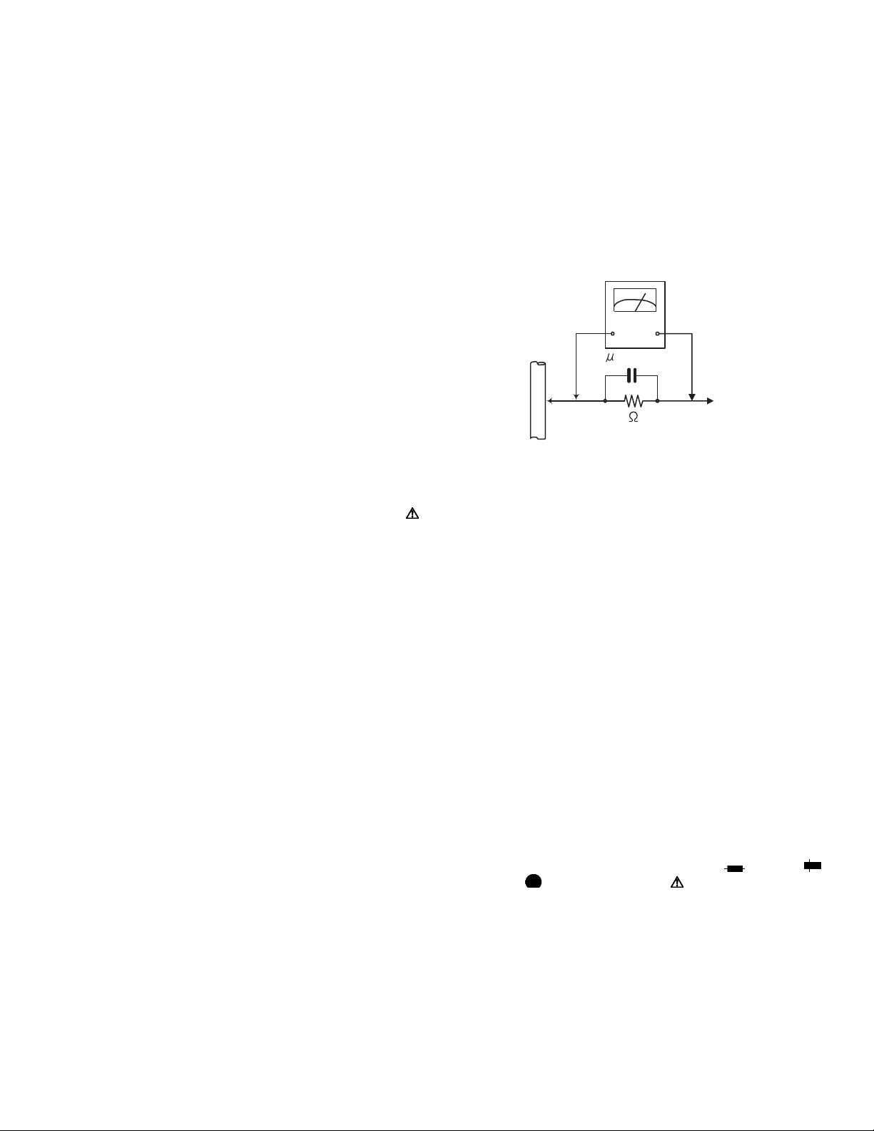
• Alternate check method
Plug the AC line cord directly into the AC outlet. Use an
AC voltmeter having, 1,000
in the following manner. Connect a 1,500
paralleled by a 0.15
exposed metal part and a known good earth ground.
Measure the AC voltage across the resistor with the AC
Ω per volt or more sensitivity
Ω 10W resistor
µF AC-type capacitor between an
voltmeter.
Move the resistor connection to each exposed metal
part, particularly any exposed metal part having a return
path to the chassis, and measure the AC voltage across
the resistor. Now, reverse the plug in the AC outlet and
repeat each measurement. Voltage measured any must
not exceed 0.75 V AC (r.m.s.). This corresponds to 0.5
mA AC (r.m.s.).
AC VOLTMETER
(Having 1000
ohms/volts,
or more sensitivity)
0.15 F AC TYPE
Place this
probe on
1500 10W
Good earth ground
1.2 Warning
(1) This equipment has been designed and manufactured to
meet international safety standards.
(2) It is the legal responsibility of the repairer to ensure that
these safety standards are maintained.
(3) Repairs must be made in accordance with the relevant
safety standards.
(4) It is essential that safety critical components are replaced
by approved parts.
(5) If mains voltage selector is provided, check setting for local
voltage.
1.3 Caution
Burrs formed during molding may be left over on some parts
of the chassis.
Therefore, pay attention to such burrs in the case of preforming repair of this system.
1.4 Critical parts for safety
In regard with component parts appearing on the silk-screen
printed side (parts side) of the PWB diagrams, the parts that are
printed over with black such as the resistor ( ), diode ( )
and ICP ( ) or identified by the " " mark nearby are critical
for safety. When replacing them, be sure to use the parts of the
same type and rating as specified by the manufacturer.
(This regulation dose not Except the J and C version)
each exposed
metal part.
(No.MB334)1-3
Page 4
1.5 Preventing static electricity
Electrostatic discharge (ESD), which occurs when static electricity stored in the body, fabric, etc. is discharged, can destroy the laser
diode in the traverse unit (optical pickup). Take care to prevent this when performing repairs.
1.5.1 Grounding to prevent damage by static electricity
Static electricity in the work area can destroy the optical pickup (laser diode) in devices such as laser products.
Be careful to use proper grounding in the area where repairs are being performed.
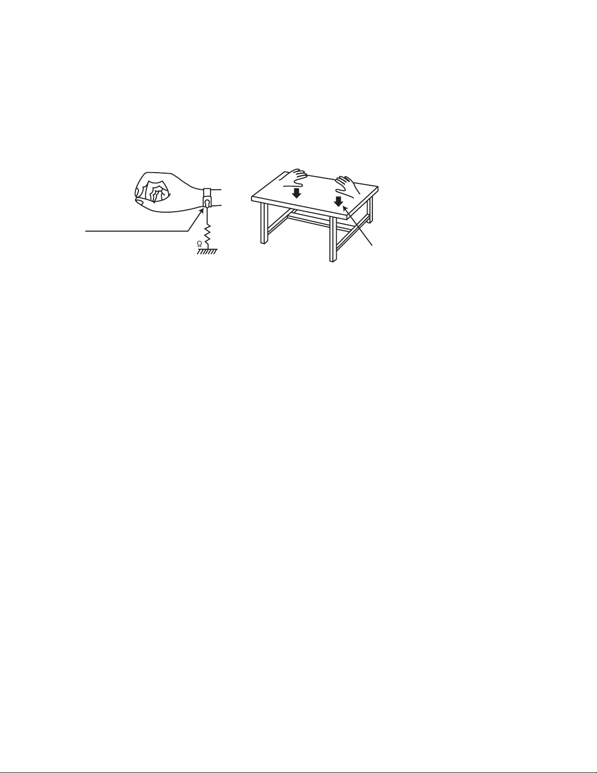
(1) Ground the workbench
Ground the workbench by laying conductive material (such as a conductive sheet) or an iron plate over it before placing the
traverse unit (optical pickup) on it.
(2) Ground yourself
Use an anti-static wrist strap to release any static electricity built up in your body.
(caption)
Anti-static wrist strap
1M
Conductive material
(conductive sheet) or iron palate
(3) Handling the optical pickup
• In order to maintain quality during transport and before installation, both sides of the laser diode on the replacement optical
pickup are shorted. After replacement, return the shorted parts to their original condition.
(Refer to the text.)
• Do not use a tester to check the condition of the laser diode in the optical pickup. The tester's internal power source can easily
destroy the laser diode.
1.6 Handling the traverse unit (optical pickup)
(1) Do not subject the traverse unit (optical pickup) to strong shocks, as it is a sensitive, complex unit.
(2) Cut off the shorted part of the flexible cable using nippers, etc. after replacing the optical pickup. For specific details, refer to the
replacement procedure in the text. Remove the anti-static pin when replacing the traverse unit. Be careful not to take too long a
time when attaching it to the connector.
(3) Handle the flexible cable carefully as it may break when subjected to strong force.
(4) I t is not possible to adjust the semi-fixed resistor that adjusts the laser power. Do not turn it.
1-4 (No.MB334)
Page 5

1.7 Attention when pickup unit is removed
r
1.7.1 Attention when MD pickup unit is removed
*Please refer to "DISASSEMBLY" in the text.
(1) Apply solder to short land section before the flexible wire is disconnected from the connector CN310 on the MD servo control
board.
(If the flexible wire is disconnected without applying solder, the pickup may be destroyed by static electricity.)
(2) In the assembly, be sure to remove solder from the short land section after connecting the flexible wire.
MD servo control board
MD servo control board
CN310
Short land section
Flexible wire
Pickup
(3) Apply solder to short land section before the flexible wire is disconnected from the connector on the pickup.
(If the flexible wire is disconnected without applying solder, the pickup may be destroyed by static electricity.)
(4) In the assembly, be sure to remove solder from the short land section after connecting the flexible wire.
Pickup
Short land section
Flexible wire
1.7.2 Attention when DVD pickup unit is removed
*Please refer to "DISASSEMBLY" in the text.
(1) Apply solder to short land sections before the card wire is disconnected from the connector on the pickup.
(If the card wire is disconnected without applying solder, the pickup may be destroyed by static electricity.)
(2) In the assembly, be sure to remove solder from the short land sections after connecting the card wire.
Short land sections
Pickup
Card wire
Connecto
(No.MB334)1-5
Page 6
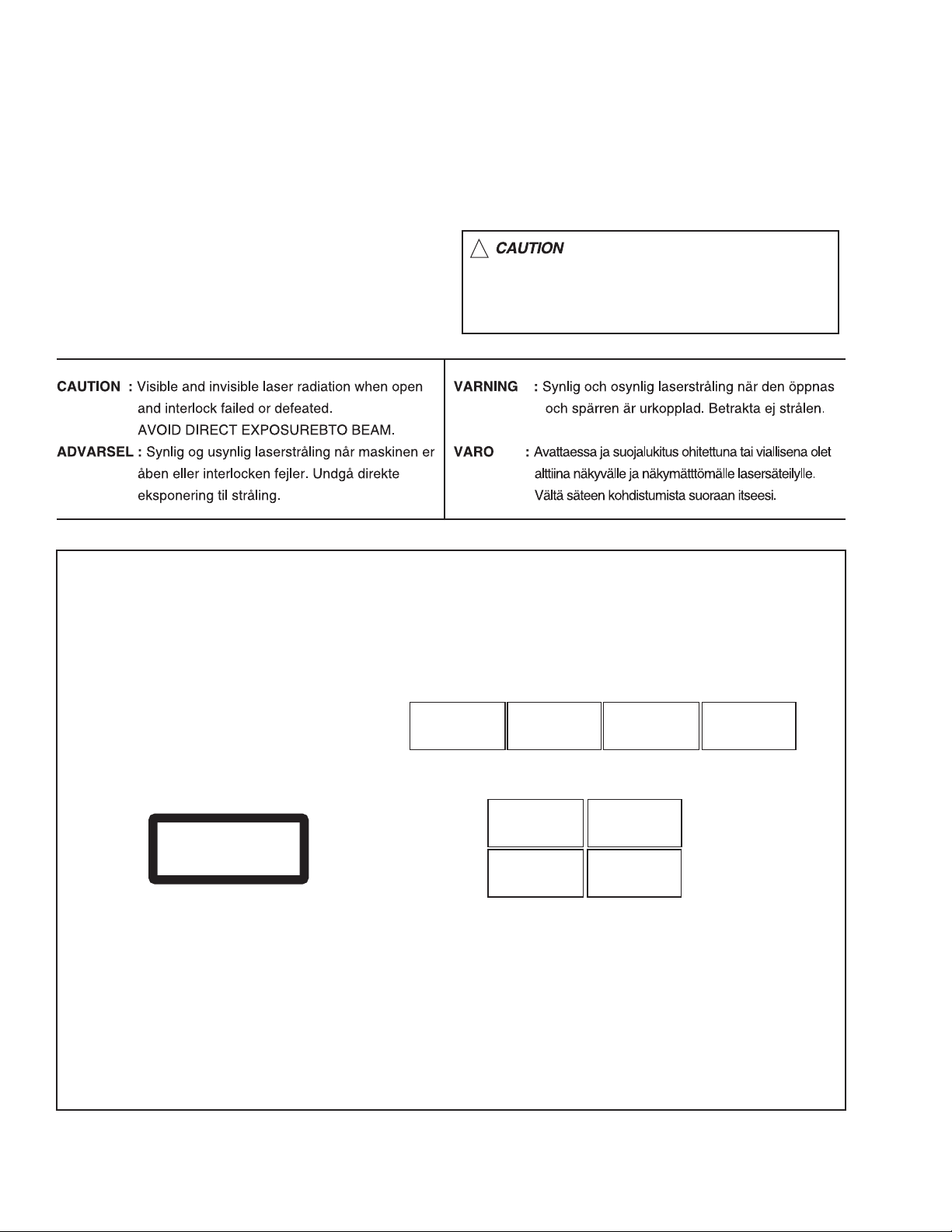
1.8 Important for laser products
!
1.CLASS 1 LASER PRODUCT
2.DANGER : Invisible laser radiation when open and inter
lock failed or defeated. Avoid direct exposure to beam.
3.CAUTION : There are no serviceable parts inside the
Laser Unit. Do not disassemble the Laser Unit. Replace
the complete Laser Unit if it malfunctions.
4.CAUTION : The CD,MD and DVD player uses invisible
laser radiation and is equipped with safety switches which
prevent emission of radiation when the drawer is open and
the safety interlocks have failed or are defeated. It is
dangerous to defeat the safety switches.
5.CAUTION : If safety switches malfunction, the laser is able
to function.
6.CAUTION : Use of controls, adjustments or performance of
procedures other than those specified here in may result in
hazardous radiation exposure.
Please use enough caution not to
see the beam directly or touch it
in case of an adjustment or operation
check.
REPRODUCTION AND POSITION OF LABELS
WARNING LABEL
CAUTION : Visible and Invisible
laser radiation when open and
interlock failed or defeated.
AVOID DIRECT EXPOSURE TO
BEAM. (e)
CLASS 1
LASER PRODUCT
ADVARSEL : Synlig og usynlig
laserstråling når maskinen er
åben eller interlocken fejeler.
Undgå direkte eksponering til
stråling. (d)
CAUTION : Visible and Invisible
laser radiation when open and
interlock failed or defeated.
AVOID DIRECT EXPOSURE TO
BEAM. (e)
VARNING : Synlig och
osynling laserstrålning när
den öppnas och spärren är
urkopplad. Betrakta ej
strålen. (s)
VARNING : Synlig och
osynling laserstrålning när
den öppnas och spärren är
urkopplad. Betrakta ej
strålen. (s)
VARO : Avattaessa ja suojalukitus
ohitettuna tai viallisena olet alttiina
näkyvälle ja näkymättömälle
lasersäteilylle. Vältä säteen
kohdistumista suoraan itseesi. (f)
ADVARSEL : Synlig og usynlig
laserstråling når maskinen er
åben eller interlocken fejeler.
Undgå direkte eksponering til
stråling. (d)
VARO : Avattaessa ja suojalukitus
ohitettuna tai viallisena olet alttiina
näkyvälle ja näkymättömälle
lasersäteilylle. Vältä säteen
kohdistumista suoraan itseesi. (f)
1-6 (No.MB334)
Page 7

SECTION 2
SPECIFIC SERVICE INSTRUCTIONS
This service manual does not describe SPECIFIC SERVICE INSTRUCTIONS.
(No.MB334)1-7
Page 8
SECTION 3
DISASSEMBLY
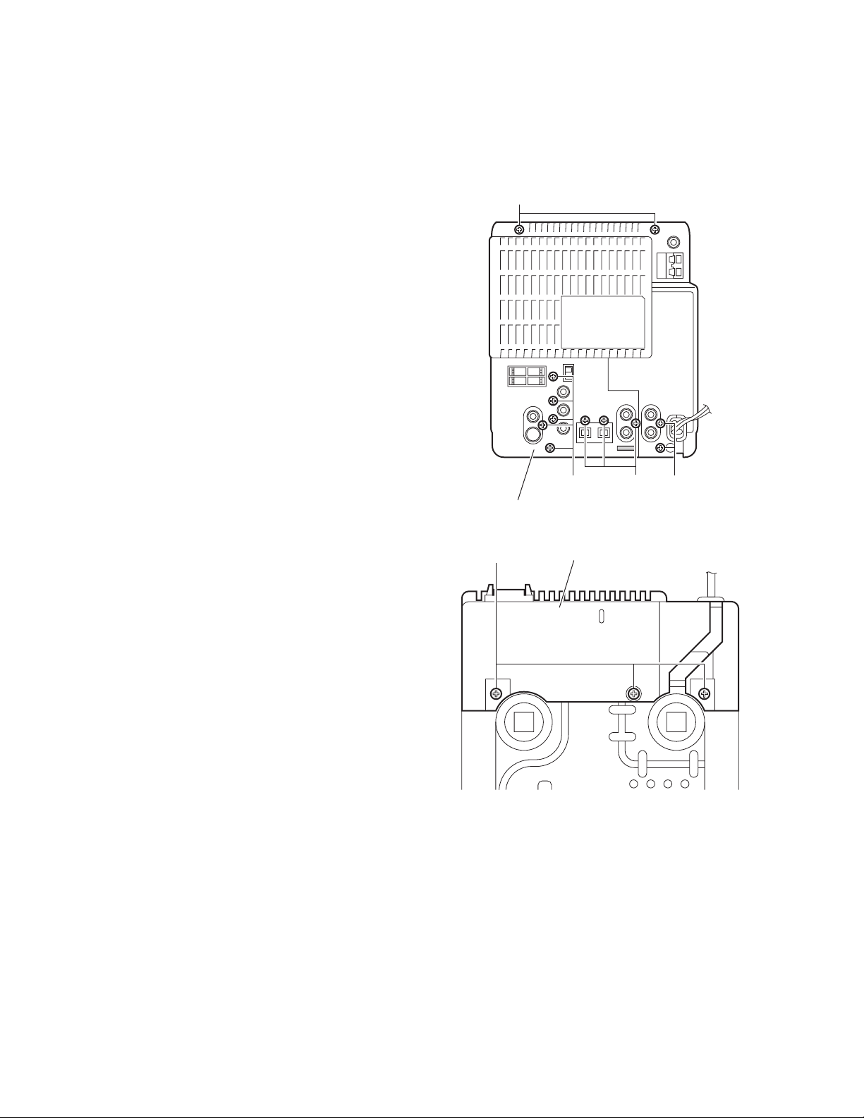
3.1 Main body section
3.1.1 Removing the rear cover
(See Figs.1 and 2)
(1) From the back side of the main body, remove the twelve
screws A attaching the rear cover. (See Fig.1.)
(2) From the bottom side of the main body, remove the three
screws B attaching the rear cover. (See Fig.2.)
(3) Remove the rear cover from the main body.
A
Rear cover
B
A AA
Fig.1
Rear cover
Fig.2
1-8 (No.MB334)
Page 9
3.1.2 Removing the side panels (L)/(R)
(See Fig.3)
• Remove the rear cover.
(1) From the bottom side of the main body, remove the two
screws C attaching the side panels (L)/(R).
(2) Slide the side panels (L)/(R) in the direction of the arrow
and remove the side panels (L)/(R).
C
Side panel(R)
3.1.3 Removing the top cover assembly
(See Figs.4 and 5)
• Remove the rear cover and side panels(L)/(R).
(1) From the left side of the main body, disconnect the card
wires from the connectors (CN703
board. (See Fig.4.)
(2) Remove the screw D attaching the top cover assembly.
(See Fig.4.)
(3) From the right side of the main body, disconnect the card
wire from the connector CN105
Fig.5.)
(4) Disconnect the wire from the connector CN108 on the main
board. (See Fig.5.)
Reference:
When connecting the wire, pass it through the slot b of
the main board as before. (See Fig.5.)
(5) From the both sides of the main body, remove the two
screws E and screw F attaching the top cover assembly.
(See Figs.4 and 5.)
(6) Release the joints a and remove the top cover assembly.
(See Figs.4 and 5.)
, CN709) on the micon
on the main board. (See
C
E
Side panel(R)
Fig.3
Top cover assembly a
Fig.4
Top cover assembly
a CN108 CN105
ED
Micon boardCN703 CN709
F
b
Main board
Fig.5
(No.MB334)1-9
Page 10
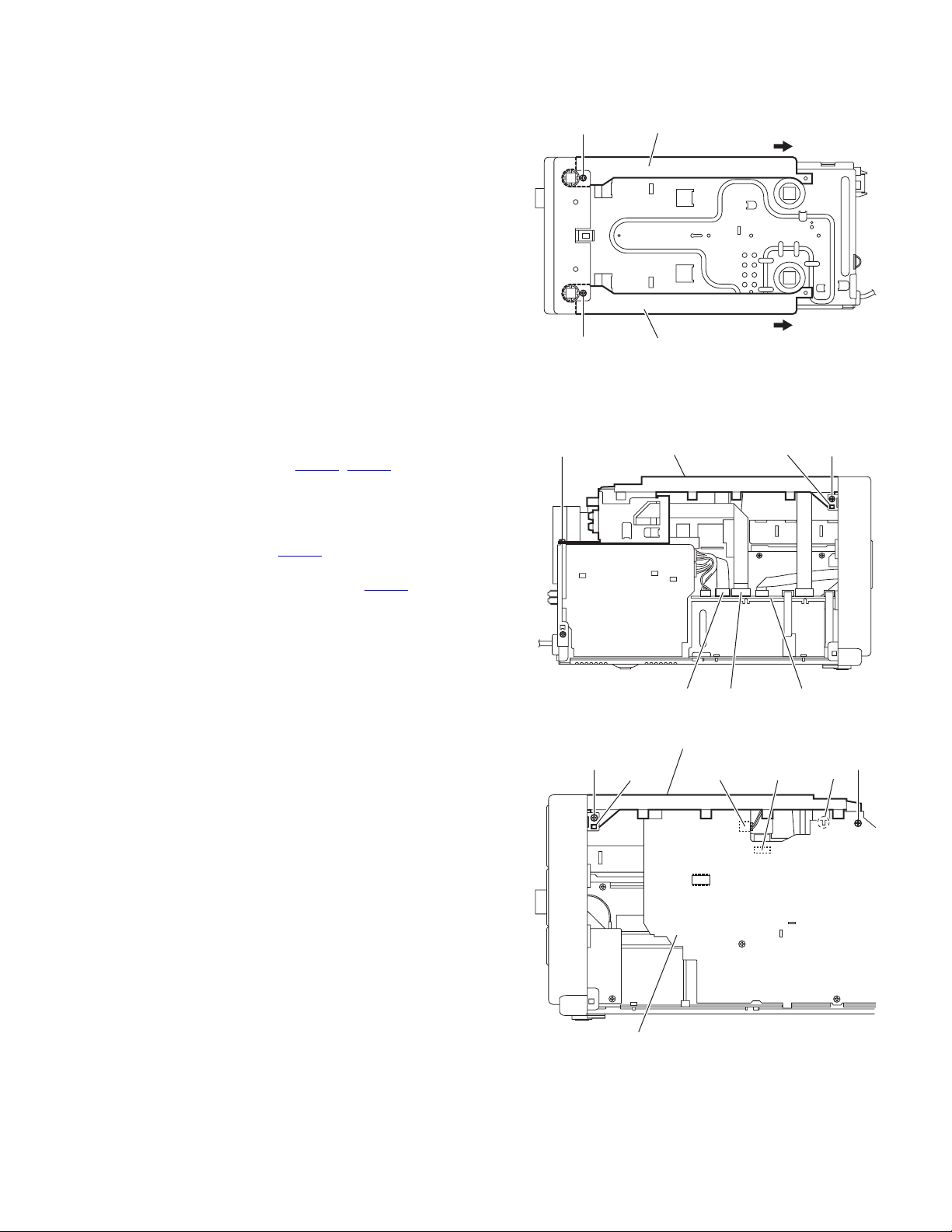
3.1.4 Removing the front panel assembly
(See Figs.6 to 8)
• Remove the rear cover, side panels(L)/(R) and top cover as-
sembly.
(1) From the left side of the main body, disconnect the card
wires from the connectors (CN702
board. (See Fig.6.)
(2) From the right side of the main body, disconnect the earth
wire from the micon board. (See Fig.6.)
(3) From the both sides and bottom sides of the main body, re-
lease the joints c and joint d. (See Figs.6 to 8.)
(4) Remove the front panel assembly in the direction of the ar-
row. (See Figs.6 to 8.)
, CN710) on the micon
Front panel assembly
CN710
CN702
Micon board
c
Front panel assembly
d
c
Fig.6
Earth wire
Fig.7
Front panel assembly
Micon board
1-10 (No.MB334)
Fig.8
Page 11
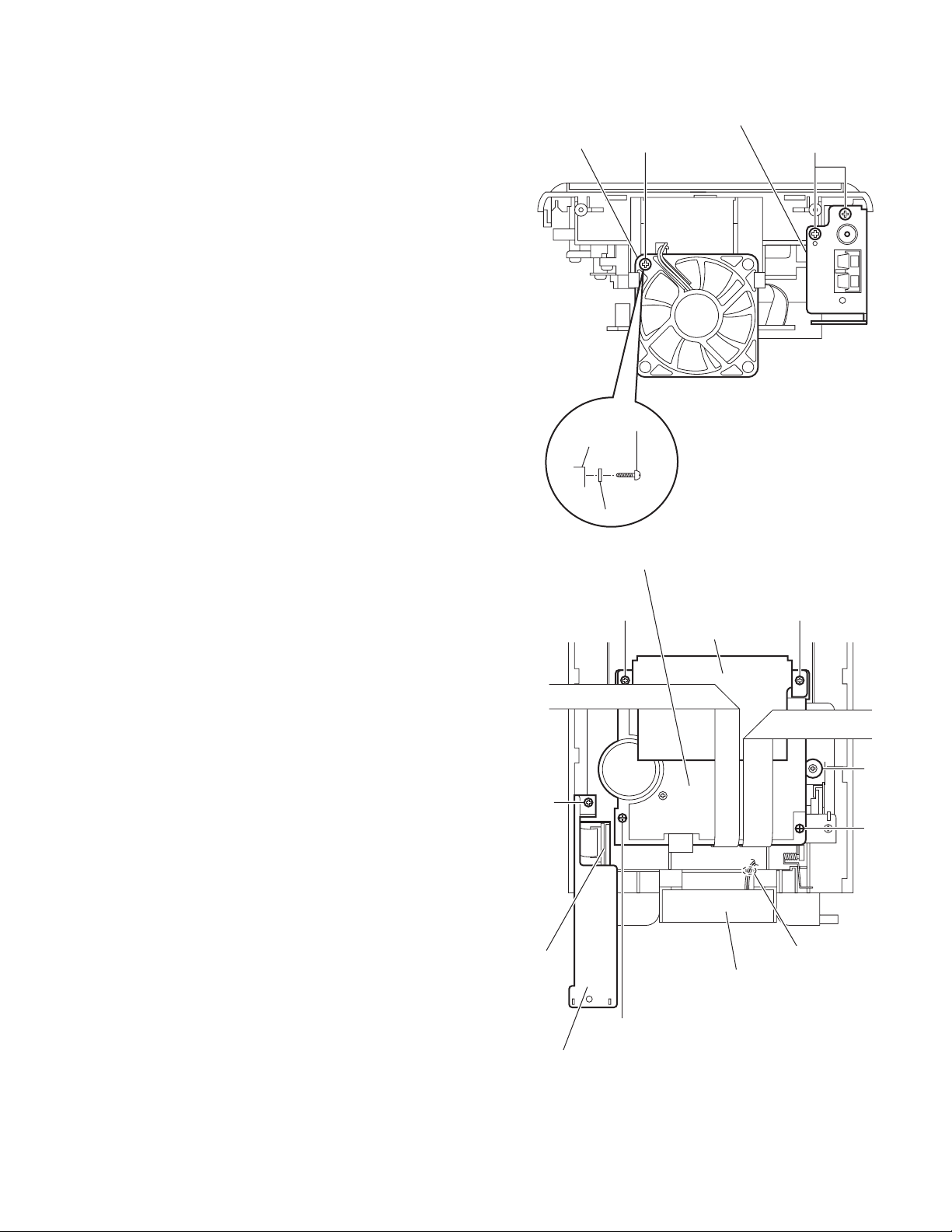
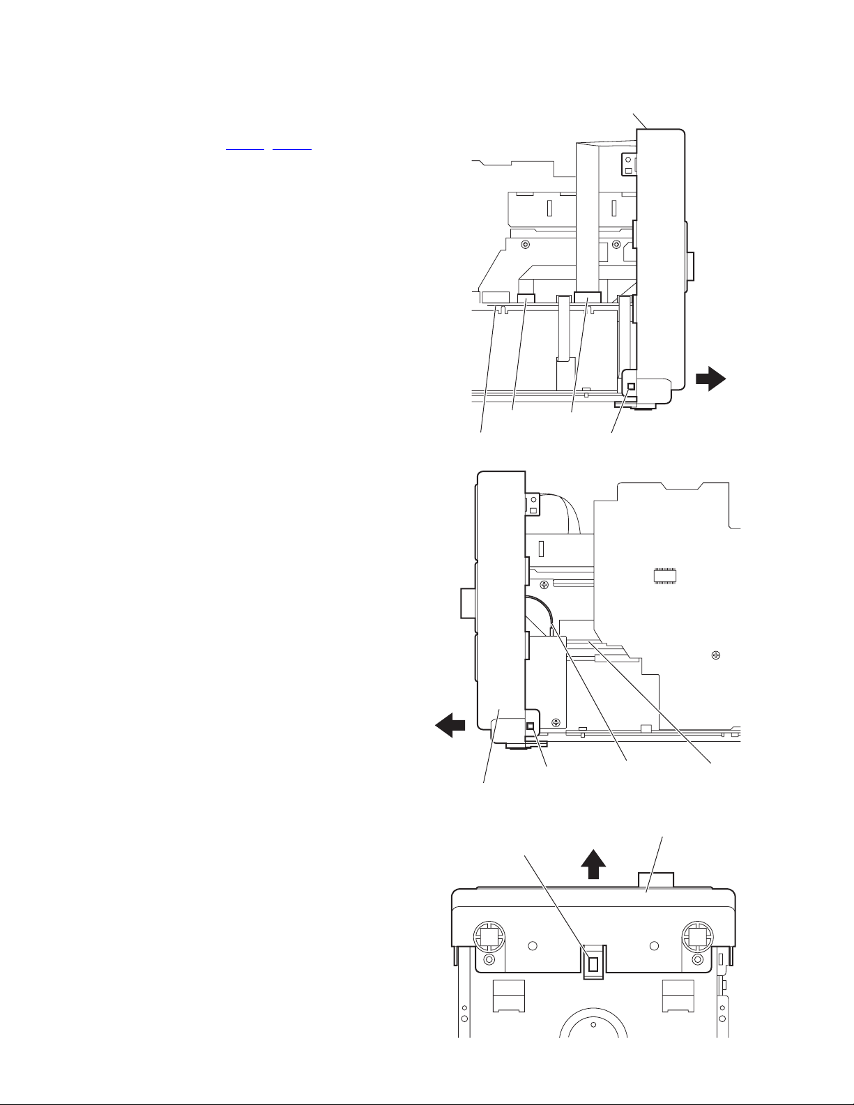
3.1.5 Removing the fan motor
(See Figs.9 and 10)
• Remove the rear cover, side panels(L)/(R) and top cover as-
sembly.
(1) From the back side of the top cover assembly, remove the
screw G attaching the fan motor. (See Fig.9.)
Reference:
When attaching the screws G, attach the spacer with it.
(See Fig.9.)
(2) Take out the fan motor.
Reference:
When attaching the fan motor, pass the wire through the
slot e. (See Fig.10.)
3.1.6 Removing the tuner
(See Figs.9 and 10)
• Remove the rear cover, side panels(L)/(R) and top cover as-
sembly.
(1) From the back side of the top cover assembly, remove the
two screws H attaching the tuner bracket. (See Fig.9.)
(2) From the inside of the top cover assembly, remove the
screw J attaching the tuner bracket. (See Fig.10.)
(3) Take out the tuner with the tuner bracket.
(4) Remove the tuner from the tuner bracket.
Fan motor
Fan motor
G
G
Tuner bracket
H
3.1.7 Removing the cassette mechanism assembly
(See Fig.10)
• Remove the rear cover, side panels(L)/(R) and top cover as-
sembly.
(1) From the inside of the top cover assembly, remove the
screw K, screw L and two screws L’ attaching the cassette
mechanism assembly.
(2) Loosen the screw M attaching the cassette mechanism as-
sembly.
(3) Remove the cassette mechanism assembly.
Reference:
When attaching the screws L’, attach the shield with them.
Spacer
Cassette mechanism assembly
J
Tuner
Fig.9
L'L'
Shield
M
K
e
Fan motor
Tuner bracket
L
Fig.10
(No.MB334)1-11
Page 12
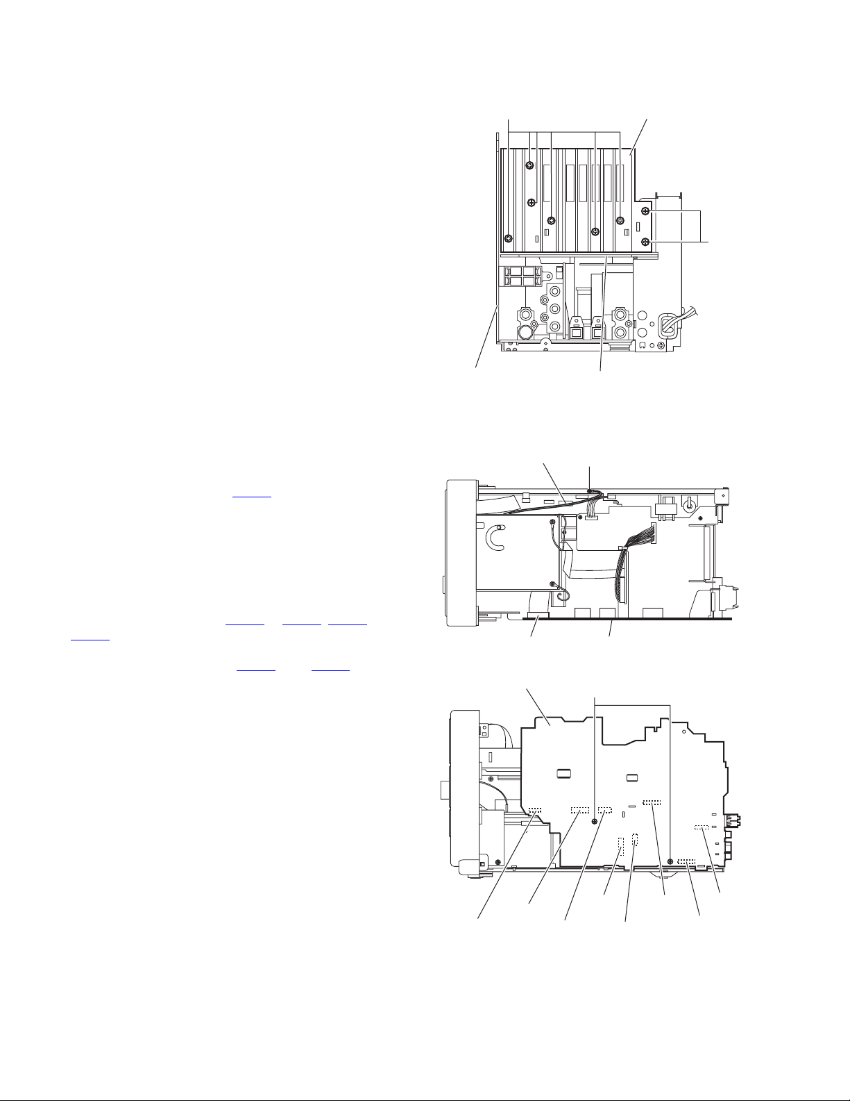
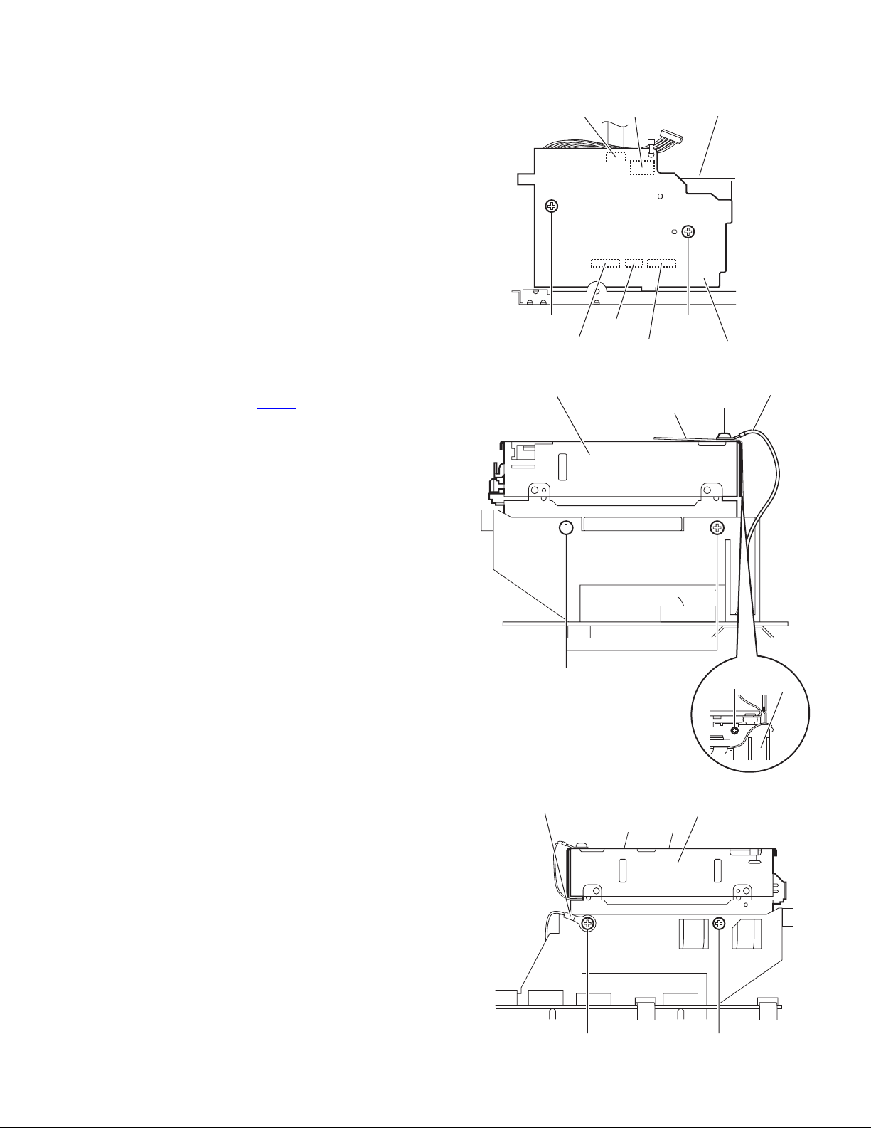
3.1.8 Removing the heat sink
(See Fig.11)
• Remove the rear cover, side panels(L)/(R) and top cover as-
sembly.
(1) From the back side of the main body, remove the eight
screws N attaching the heat sink.
(2) Remove the heat sink from the main board and regulator
board.
N
Heat sink
N
3.1.9 Removing the main board
(See Figs.12 and 13)
• Remove the rear cover, side panels(L)/(R), top cover assem-
bly and heat sink.
(1) From the forward side of the main board, disconnect the
card wire from the connector CN107
Reference:
Remove it when a lug wire from the main board is installed with a screw P.
(When the screw P and lug wire are installed, apply it.)
(See Fig.12.)
(2) From the right side of the main body, remove the two
screws Q attaching the main board. (See Fig.13.)
(3) Disconnect the connectors (CN101
CN110) on the main board toward this side. (See Fig.13.)
(4) From the forward side of the main board, disconnect the
wires from the connectors (CN109
Fig.13.)
. (See Fig.12.)
to CN104, CN106 and
and CN111). (See
Main board
Main board
Lug wire
CN107
Regulator board
Fig.11
P
Main board
Fig.12
Q
1-12 (No.MB334)
CN104
CN103
CN102
Fig.13
CN111
CN101CN106
CN109
CN110
Page 13
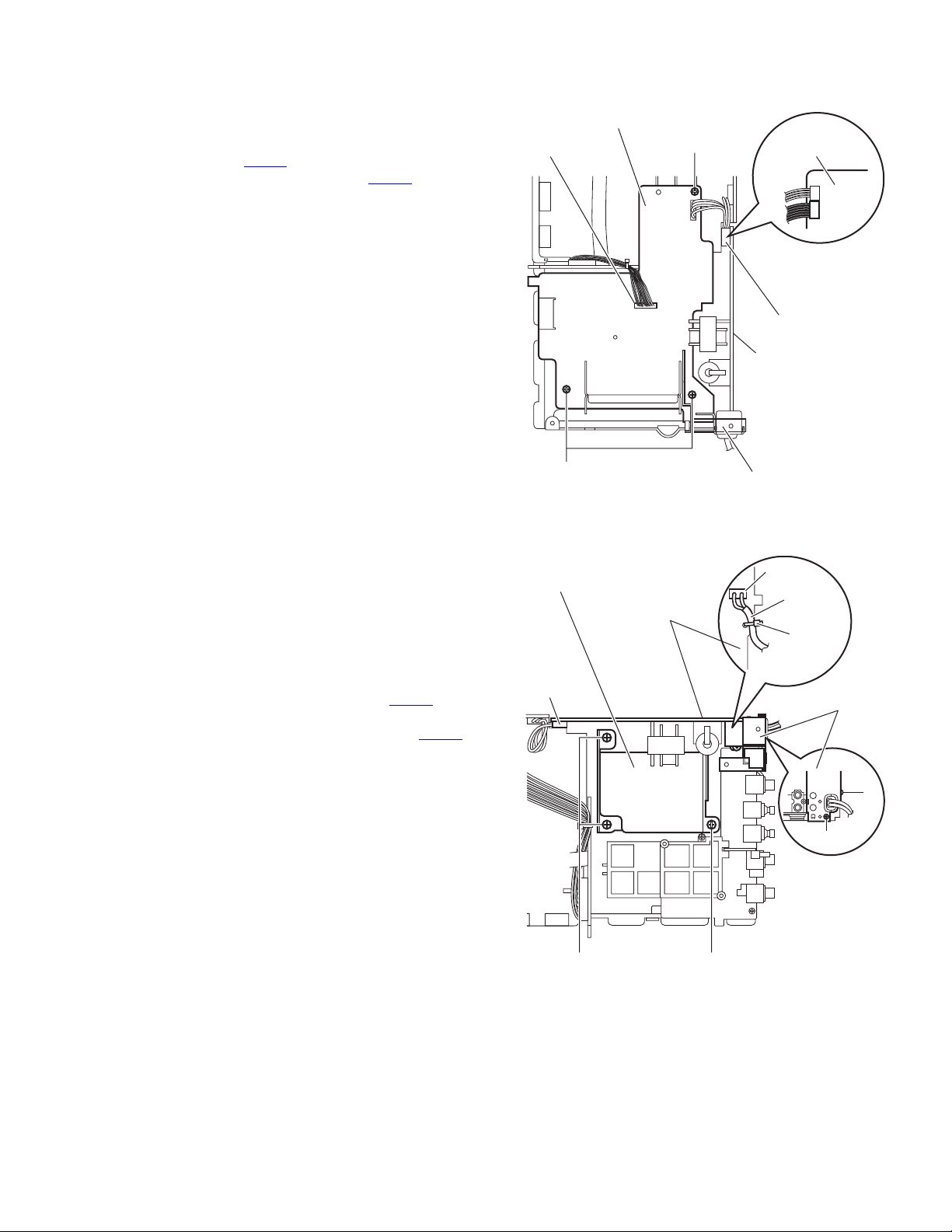
3.1.10 Removing the regulator board
(See Fig.14)
• Remove the rear cover, side panels(L)/(R), top cover assem-
bly, heat sink and main board.
(1) From the top side of the main body, disconnect the wire
from the connector CN902
(2) Disconnect the wire from the connector CN202
ulator board.
(3) Remove the three screws R attaching the regulator board.
(4) Take out the regulator board from the main body.
Reference:
After attaching the regulator board, attach the barrier as before.
on the transformer board.
on the reg-
Regulator board
CN202
R
Transformer
board
CN902
CN902
Transformer
board
3.1.11 Removing the transformer board
(See Fig.15)
• Remove the rear cover, side panels(L)/(R), top cover assem-
bly, heat sink, main board and regulator board.
(1) From the back side of the main body, remove the two
screws S attaching the heat sink bracket.
(2) From the left side of the main body, remove the tie band.
Reference:
After attaching the transformer board, fix the power cord
with the new tie band as before.
(3) Disconnect the wire from the connector CN903
transformer board.
(4) Disconnect the power cord from the connector CN901 on
the transformer board.
(5) Remove the three screws T attaching the power transform-
er and take out the transformer board from the main body.
Reference:
Remove the transformer shield as required.
on the
R
Transformer shield
Transformer board
CN903
Barrier
Fig.14
CN901
Power cord
Tie band
Heat sink
bracket
S
S
TT
Fig.15
(No.MB334)1-13
Page 14
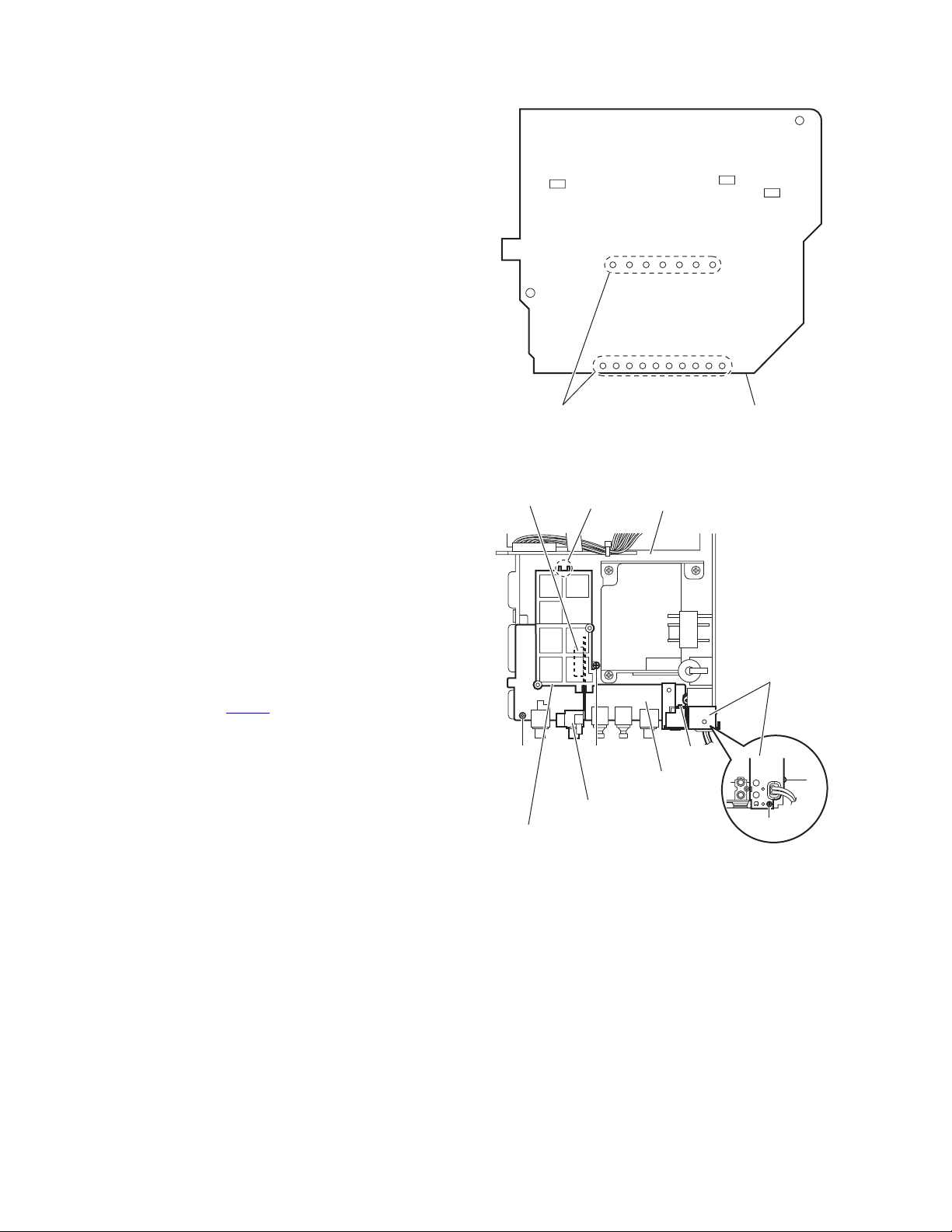
3.1.12 Removing the power transformer
(See Fig.16)
• Remove the rear cover, side panels(L)/(R), top cover assem-
bly, heat sink, main board, regulator board and transformer
board.
(1) From the reverse side of the transformer board, remove the
solders from the sections f on the transformer board.
(2) Remove the power transformer from the transformer
board.
3.1.13 Removing the jack board and component board
(See Fig.17)
• Remove the rear cover, side panels(L)/(R), top cover assem-
bly, heat sink, main board and regulator board.
(1) From the back side of the main body, remove the two
screws U attaching the heat sink bracket.
(2) From the top side of the main body, remove the screw V at-
taching the PWB holder and take out the PWB holder.
Reference:
When attaching the PWB holder, put the section g under
the hook of the bottom chassis.
(3) Remove the screw W attaching the jack board and take out
the jack board with the component board.
Reference:
• Remove the connector CN631
from the jack board as required.
• When attaching the jack board, attach it after putting a projection h of the bottom chassis in a hole of the jack board.
on the component board
f
CN631
W
Component board
PWB holder
g
Bottom chassis
V
Fig.16
h
Jack board
Fig.17
Transformer board
Heat sink
bracket
U
U
1-14 (No.MB334)
Page 15
3.1.14 Removing the joint board
(See Fig.18)
• Remove the rear cover, side panels(L)/(R), top cover assem-
bly, heat sink, main board, regulator board and transformer
board.
Reference:
Remove the jack board as required.
(1) From the back side of the main body, remove the two
screws X attaching the joint board.
(2) Remove the connector CN805
micon board toward this side.
(3) From the forward side of the joint board, disconnect the
card wires from the connectors (CN801
joint board.
(4) Take out the joint board from the main body.
on the joint board from the
to CN804) on the
CN803
CN805
Micon board
3.1.15 Removing the MD mechanism assembly
(See Figs.18 and 20)
• Remove the rear cover, side panels(L)/(R), top cover assem-
bly, front panel assembly, heat sink and main board.
(1) From the back side of the main body, disconnect the card
wire from the connector CN803
Fig.8.)
(2) Remove the screw Y attaching the MD mechanism assem-
bly. (See Fig.19.)
(3) From the right side of the main body, remove the screw Z
attaching the MD mechanism assembly. (See Fig.19.)
Reference:
When attaching the screw Z, attach it with the lug and
shield (C). (See Fig.19.)
(4) From the both sides of the main body, remove the three
screws AA and screw AA’ attaching the MD mechanism
assembly. (See Figs.19 and 20.)
Reference:
When attaching the screw AA’, attach the lug wire with
it. (See Fig.20.)
(5) Take out the MD mechanism assembly from the main
body.
on the joint board. (See
X
MD mechanism assembly
CN804
CN801
AA
CN802
Fig.18
Shield (C)
X
Joint board
Lug wire
Z
MD
Y
holder
Lug wire
AA'
Fig.19
MD mechanism assembly
AA
Fig.20
(No.MB334)1-15
Page 16

3.1.16 Removing the micon board
(See Figs.21 and 22)
• Remove the rear cover, side panels(L)/(R), top cover assem-
bly, front panel assembly, heat sink, main board and regulator
board.
(1) From the top side of the main body, disconnect the card
wire from the connector CN803
Fig.21.)
(2) Remove the screw AB and screw AB’ attaching the MD
holder to the micon board. (See Fig.21.)
(3) Take out the MD holder with the MD mechanism assembly.
Reference:
When attaching the screw AB’, attach the lug wire with
it. (See Fig.21.)
(4) Disconnect the wire from the connector CN903
transformer board. (See Fig.22.)
(5) Disconnect the card wires from the connectors (CN705
CN711) on the micon board. (See Fig.22.)
(6) Remove the screw AC attaching the micon board. (See
Fig.22.)
(7) Disconnect the micon board from the connector CN805
the joint board. (See Fig.22.)
(8) Take out the micon board from the main body.
on the joint board. (See
on the
and
on
Micon board
CN711
MD mechanism assembly
Lug wire
CN705
AB'
Fig.21
MD holder
AB
CN803
Joint board
Transformer board
CN903
1-16 (No.MB334)
AC
Micon board
Fig.22
Joint board
CN805
Page 17

3.1.17 Removing the DVD mechanism assembly
(See Figs.23 and 24)
• Remove the rear cover, side panels(L)/(R), top cover assem-
bly, heat sink, main board, regulator board, transformer board
and joint board.
(1) From the top side of the main body, disconnect the card
wires from the connectors (CN705
con board. (See Fig.23.)
(2) From the left side of the main body, remove the spacers fix-
ing the card wires. (See Fig.23.)
(3) From the top side of the main body, remove the two screws
AD attaching the DVD mechanism bracket. (See Fig.23.)
(4) Move the DVD mechanism bracket in the direction of the
arrow to release the claws i and remove the DVD mechanism bracket. (See Fig.23.)
(5) Remove the screw AE attaching the DVD mechanism as-
sembly. (See Fig.24.)
(6) Take out the DVD mechanism assembly from the main
body. (See Fig.24.)
and CN711) on the mi-
Spacer
CN711
CN711
Card
wire
AD
CN705
Spacer
CN705
Card
wire
Micon board
i
AD
DVD mechanism bracket
Fig.23
DVD mechanism assembly
Fig.24
i
AE
(No.MB334)1-17
Page 18

3.1.18 Removing the headphone board
(See Fig.25)
• Remove the rear cover, side panels(L)/(R), top cover assem-
bly, heat sink, main board, regulator board, transformer board,
joint board and DVD mechanism assembly.
(1) From the right side of the main body, remove the screw AF
attaching the headphone board.
(2) Take out the headphone board from the main body.
Reference:
• When attaching the headphone board, put the headphone
board in the slot j.
• When attaching the headphone board, pass the wire
through the section k.
• After attaching the headphone board, fix the wires with the
spacers as before.
3.1.19 Removing the FL board
(See Fig.26)
• Remove the rear cover, side panels(L)/(R), top cover assem-
bly and front panel assembly.
(1) From the inside of the front panel assembly, remove the
three screws AG attaching the FL board.
(2) Take out the FL board from the front panel assembly.
Note:
When attaching the FL board, be careful not to damage the
LCD panel.
Headphone board
j
AF
AG
Spacer
k
Fig.25
Front panel assembly
FL board
Spacer
AG
3.1.20 Removing the key board
(See Figs.26 and 27)
• Remove the rear cover, side panels(L)/(R), top cover assem-
bly and front panel assembly.
(1) From the front side of the front panel assembly, pull out the
volume knob in the direction of the arrow. (See Fig.27.)
(2) From the inside of the front panel assembly, remove the six
screws AH attaching the key board. (See Fig.26.)
(3) Take out the key board from the front panel assembly.
AH
Key board
AH
Fig.26
Front panel assembly
1-18 (No.MB334)
Volume knob
Fig.27
Page 19

3.2 DVD mechanism assembly section
• Remove the DVD mechanism assembly from the main body.
(See "3.1.17 Removing the DVD mechanism assembly".)
3.2.1 Removing the DVD cover
(See Fig.1)
(1) From the top side of the DVD mechanism assembly, re-
move the two screws A attaching the DVD cover.
(2) Remove the double-stick tape fixing the card wire.
(3) Lift the DVD cover in an upward direction and remove it
from the projections a of the DVD mechanism assembly.
(4) Slide the DVD cover in the direction of the arrow and re-
move it from the sections b.
(5) Release the lock of the connector CN4
and disconnect the card wire.
on the LED board
Double-stick tape
Card wire
CN4
A
a
b
Card wire
LED board
3.2.2 Removing the joint board
(See Fig.2)
• Remove the DVD cover.
(1) From the inside of the DVD cover, remove the screw B at-
taching the joint board.
(2) Remove the spacer attaching the joint board and take out
the joint board from the DVD cover.
a
A
DVD mechanism assembly
Clamper base
B
Clamper base
Fig.1
Joint board
Fig.2
b
Spacer
(No.MB334)1-19
Page 20

3.2.3 Removing the tray assembly
(See Figs.3 and 4)
• Remove the DVD cover.
(1) From the right side of the DVD mechanism assembly, push
the slide cam and pull the tray assembly out of the DVD
mechanism assembly in the direction of the arrow. (See
Fig.3.)
(2) From the top side of the DVD mechanism assembly, re-
move the two screws C attaching the tray assembly. (See
Fig.4.)
(3) Remove the bushing of the tray assembly from the projec-
tions c on the DVD mechanism assembly and take out the
tray assembly in an upward direction. (See Fig.4.)
Tray assembly DVD mechanism assembly
Slide cam
Fig.3
C
c
Shaft guide
c
3.2.4 Removing the LED board
(See Fig.5)
• Remove the DVD cover and tray assembly.
(1) From the top side of the tray assembly, remove the sec-
tions d which were fixed in bond.
(2) Remove the double-stick tape attaching the LED board and
take out the LED board.
Note:
When removing the LED board, be sure not to damage the
LED board.
DVD mechanism assembly
Fig.4
Tray assembly
Double-stick tape
Fig.5
Tray assembly
d
d
LED board
1-20 (No.MB334)
Page 21

3.2.5 Removing the traverse mechanism assembly
(See Figs.6)
• Remove the DVD cover.
(1) From the bottom side of the DVD mechanism assembly, re-
move the four screws D attaching the traverse mechanism
assembly.
(2) Take out the traverse mechanism assembly with the DVD
module board.
DVD mechanism assembly
DVD module board
3.2.6 Removing the DVD module board
(See Figs.7 and 8)
• Remove the DVD cover and traverse mechanism assembly.
(1) From the side of the traverse mechanism assembly, solder
the short land sections e of the pickup. (See Fig.7.)
(2) From the bottom side of the traverse mechanism assem-
bly, release the lock of the connector CN101
module board in the direction of the arrow and disconnect
the card wire. (See Fig.8.)
Caution:
• Solder the short land section e on the pickup before
disconnecting the card wire from the connector CN101
on the DVD module board. If the card wire is disconnected without attaching solder, the pickup may be destroyed by static electricity. (See Figs.7 and 8.)
• When attaching the DVD module board, be sure to remove solders from the short land section e after connecting the card wire to the connector CN101
DVD module board. (See Figs.7 and 8.)
(3) Disconnect the card wire from the connector CN201
DVD module board. (See Fig.8.)
(4) Remove the two screws E attaching the DVD module
board. (See Fig.8.)
(5) Remove the DVD module board from the projection f in an
upward direction and remove the claw h in the direction of
the arrow 2 while removing the claw g in the direction of the
arrow 1. (See Fig.8.)
on the DVD
on the
on the
D
Traverse mechanism assembly
Fig.6
e
Traverse mechanism assembly
Fig.7
Card wire
CN101
f
E
1
D
Pickup
Card wire
CN201
E
h
2
g
DVD module board
Traverse mechanism assembly
Fig.8
(No.MB334)1-21
Page 22

3.2.7 Removing the pickup
(See Figs.7, 9 to 11)
• Remove the DVD cover and traverse mechanism assembly.
(1) From the side of the traverse mechanism assembly, solder
the short land sections e of the pickup. (See Fig.7.)
(2) Release the lock of the connector of the pickup in the direc-
tion of the arrow and disconnect the card wire. (See Fig.9.)
Caution:
• Solder the short land section e on the pickup before
disconnecting the card wire from the connector on the
pickup. If the card wire is disconnected without attaching solder, the pickup may be destroyed by static electricity. (See Figs.7 and 9.)
• When attaching the pickup, be sure to remove solders
from the short land section e after connecting the card
wire to the connector on the pickup. (See Figs.7 and
9.)
(3) Remove the screw F attaching the plate and thrust spring.
(See Fig.9.)
(4) Remove the plate from the joint i of the feed holder and
take out the plate with the thrust spring. (See Fig.9.)
(5) Remove the shaft of the pickup from the section j of the
traverse mechanism assembly and remove it from the section k while moving the shaft in the direction of the arrow.
(See Fig.10.)
(6) Remove the pickup from the section m of the traverse
mechanism assembly and take out the pickup with the
shaft. (See Fig.10.)
(7) From the bottom side of the pickup, remove the two screws
G attaching the SW actuator and LEAD spring. (See
Fig.11.)
(8) Pull the shaft out of the pickup. (See Fig.11.)
Plate
F
Feed holder
j
Shaft
i
Thrust spring
Card wire
Fig.9
Traverse mechanism assembly
Connector
Pickup
k
Pickup
Shaft
m
Fig.10
Pickup
SW actuator
LEAD spring
G
Fig.11
1-22 (No.MB334)
Page 23

3.2.8 Attaching the pickup
(See Figs.7, 9 to 12)
• See "3.2.7 Removing the pickup".
(1) Attach the shaft, SW actuator and LEAD spring to the pick-
up. (See Fig.11.)
(2) Align the pickup to the section m of the traverse mecha-
nism assembly first, and set the both ends of the shaft of
the pickup in the sections (j, k) of the traverse mechanism
assembly. (See Fig.10.)
(3) Attach the plate and thrust spring. (See Fig.9.)
(4) Remove the solders from the soldered sections e after at-
taching the card wire to the connector on the pickup. (See
Figs.7 and 9.)
(5) Turn the feed gear M in the direction of the arrow 1 to move
the pickup fully in the direction of the arrow 2. (See Fig.12.)
Feed gear M
1
2
Pickup
Fig.12
(No.MB334)1-23
Page 24

3.2.9 Removing the feed motor
(See Figs.13 to 15)
• Remove the DVD cover and traverse mechanism assembly.
(1) From the top side of the traverse mechanism assembly, re-
move the screw H attaching the plate and thrust spring.
(See Fig.13.)
(2) Remove the plate from the joint n of the feed holder and
take out the plate with the thrust spring. (See Fig.13.)
(3) Remove the wires from the soldered sections p on the spin-
dle motor board. (See Fig.14.)
Reference:
When attaching the feed motor, pass the wires through
the section q on the spindle base. (See Fig.14.)
(4) Remove the three screws J attaching the feed holder. (See
Fig.14.)
(5) Remove the feed holder, feed motor, lead screw, feed gear
E and feed gear M simultaneously. (See Fig.14.)
(6) From the side of the feed holder, remove the two screws K
attaching the feed motor. (See Fig.15.)
3.2.10 Removing the spindle motor board
(See Fig.14 and 16)
• Remove the DVD cover, traverse mechanism assembly and
DVD module board.
(1) From the top side of the traverse mechanism assembly, re-
move the wires from the soldered sections p on the spindle
motor board. (See Fig.14.)
(2) From the bottom side of the traverse mechanism assem-
bly, remove the three screws L attaching the spindle motor
board. (See Fig.16.)
n
Plate
H
Feed gear M
Feed gear E
J
Thrust spring
Fig.13
Feed motor
Traverse mechanism assembly
Lead screw
Wires
q
p
Feed holder
J
Traverse mechanism assembly
Fig.14
K
Fig.15
Traverse mechanism assembly
L
Spindle base
Spindle motor board
Feed holder
1-24 (No.MB334)
Fig.16
Page 25

3.2.11 Removing the DVD loading switch board
(See Fig.17)
(1) From the bottom side of the DVD mechanism assembly, re-
move the screw M attaching the DVD loading switch board.
(2) Remove the wires from the soldered sections r on the DVD
loading switch board.
(3) Lift the DVD loading switch board while pressing the claw
s of the DVD mechanism assembly in the direction of the
arrow and remove the DVD loading switch board from the
section t.
(4) From the forward side of the DVD loading switch board,
disconnect the card wire from the connector CN1
Reference:
• Put the wires on the section u after attaching the DVD loading switch board to the DVD mechanism assembly.
• Fix the claw t on the DVD mechanism assembly with bonds
after attaching the DVD loading switch board.
3.2.12 Removing the motor
(See Figs.17 and 18)
• Remove the DVD cover and tray assembly.
(1) From the bottom side of the DVD mechanism assembly, re-
move the wires from the soldered sections r on the DVD
loading switch board. (See Fig.17.)
(2) From the top side of the DVD mechanism assembly, re-
move the belt from the motor pulley. (See Fig.18.)
Note:
Take care not to attach grease on the belt.
(3) Remove the two screws N attaching the motor to the DVD
mechanism assembly and take out the motor from the bottom side of the DVD mechanism assembly. (See Fig.18.)
.
DVD loading switch board
Wires
r
CN1
t
u
M
DVD mechanism
assembly
DVD mechanism assembly
Fig.17
N
s
Motor
Belt
Motor pulley
Fig.18
(No.MB334)1-25
Page 26

3.3 MD mechanism section
3.3.1 Removing the MD servo control board
(See Figs.1 and 2)
Caution:
Be sure to solder the short land section on the flexible wire
before disconnecting the flexible wire from the connector
on the MD servo control board.
CN310
If the flexible wire is disconnected without attaching solder, the
pickup may be destroyed by static electricity. (See Fig.2.)
(1) From the bottom side of the main body, disconnect the card
wire from the connector CN408
board. (See Fig.1)
(2) Disconnect the flexible wire from the connector CN407
the MD servo control board. (See Fig.1.)
(3) Remove the wires from the soldered section a on the MD
servo control board. (See Fig.1.)
(4) Remove the two screws A attaching the MD servo control
board. (See Fig.1.)
(5) Move the MD servo control board in the direction of the
arrow and remove it from the joints b of the single frame.
(See Fig.1.)
(6) From the inside of the main body, solder the short land
section on the flexible wire. (See Fig.2.)
(7) From the reverse side of the MD servo control board,
disconnect the flexible wire from the connector CN310
remove the MD servo control board. (See Fig.2.)
Caution:
When attaching the MD servo control board, remove the
solders from the short land section after connecting the flexible
wire to the connector CN310
(See Fig.2.)
on the MD servo control
on the MD servo control board.
on
and
MD servo control board
Soldered section a
Wires
(Bottom side)
Joint b
Single frame
Fig.1
MD servo control board
AA
Card wire
CN408
CN407
Flexible wire
Joint b
MD servo control board
CN310
Pickup
Fig.2
Short land
section
Flexible wire
1-26 (No.MB334)
Page 27

3.3.2 Removing the mechanism cover
r
(See Fig.3.)
(1) From the both sides of the main body, remove the four
screws B attaching the mechanism cover.
(2) Move the mechanism cover toward the front to disengage
the front hook of the mechanism cover from the internal
loading assembly (joint c). Then remove the mechanism
cover in an upward direction.
3.3.3 Removing the head lifter
(See Figs.4 to 6)
(1) Remove the head lifter spring from the hook of the main
body.
Reference:
Remove the head lifter spring from the head lifter as
required.
(2) Move the head lifter in the direction of the arrow, disengage
the joints d and e.
Joint c
Hook
Joint c
Head lifter
B
Mechanism cover
B
Fig.3
Joint d
Head lifter
Head lifter
Fig.4
Head lifte
spring
Joint e
Fig.5
Head lifter spring
Fig.6
(No.MB334)1-27
Page 28

3.3.4 Removing the MD head
(See Figs.7 and 8)
• Remove the MD servo control board.
(1) From the bottom side of the main body, remove the wire
from the H.wire holder 1. (See Fig.7.)
(2) From the top side of the main body, remove the screw C
attaching the MD head. (See Fig.8.)
Note:
• When attaching the wire, fix it to the H.wire holder 1 on the
bottom side of the pick up. (See Fig.7.)
• After attaching the wire, confirm that the rest switch is
pressed by the pickup.
Rest switch
Pickup
Wire
H.wire holder 1
Fig.7
MD head
C
Fig.8
1-28 (No.MB334)
Page 29

3.3.5 Removing the loading assembly
(See Figs.9 and 10)
Reference:
The loading assembly, traverse mechanism assembly and
single frame will be removable after removing the loading
assembly from the main body.
• Remove the MD servo control board, mechanism cover, head
lifter and MD head.
(1) From the top side of the main body, remove the three
screws D attaching the loading assembly.
(2) Move the loading assembly forward to disengage it from
the traverse mechanism assembly (joint f) and then
remove the loading assembly in an upward direction.
(3) Remove the traverse mechanism assembly from the single
frame.
Loading assembly
D
D
Joint f
D
Fig.9
Loading assembly
Traverse mechanism
assembly
Fig.10
Single frame
(No.MB334)1-29
Page 30

3.3.6 Removing the slide base L and slide base R
(See Fig.11)
(1) From the top side of the loading assembly, remove the two
screws E attaching the slide base L and slide base R.
(2) Remove the slide base L outward. (Release it from the
joints g.)
(3) Remove the slide base R outward.
3.3.7 Removing the loading mechanism assembly
(See Fig.12)
(1) Remove the loading mechanism assembly upward to
release the four pins from the both sides of the loading
mechanism base while paying attention to the section h of
the loading mechanism base.
Slide base R
Slide base L
Pin
Joint g
Joint g
Fig.11
E
E
h
Pin
Pin
Loading mechanism assembly
Fig.12
Pin
Loading mechanism base
1-30 (No.MB334)
Page 31

3.3.8 Removing the loading motor
H
r
(See Figs.13 and 14)
(1) Remove the wire from the wire holder and disconnect the
wire from the connector CN612
board. (See Fig.13.)
(2) Remove the screw F attaching the loading motor assembly
and disengage the joint i. (See Fig.13.)
(3) Remove the belt from the loading motor assembly. (See
Fig.14.)
(4) Remove the two screws G attaching the loading motor.
(See Fig.14.)
3.3.9 Removing the cam gear and MD cam switch board
(See Fig.13)
(1) Remove the slit washer attaching the cam gear and pull out
the cam gear.
(2) Remove the wire from the wire holder and disconnect the
wire from the connector CN612
board.
(3) Remove the two screws H attaching the MD cam switch
board, and remove the MD cam switch board.
on the MD cam switch
on the MD cam switch
Loading motor assembly
Wire
Wire holder
Joint i
F
CN612
Fig.13
Loading motor
MD cam switch board
H
Slit washe
H
Cam gear
G
Belt
Fig.14
(No.MB334)1-31
Page 32

3.3.10 Removing the cartridge holder assembly
(See Figs.15 and 16)
(1) From the top side of the loading assembly, remove the two
screws J attaching the slide bar and cartridge holder
assembly.
Slide bar
Cartridge holder assembly
3.3.11 Removing the slide bar and eject bar
(See Figs.15 and 16)
• Remove the cartridge holder assembly.
(1) Remove the slide bar in an upward direction.
(2) Move the eject bar outward until stops as shown in Fig.15.
Push the claw j on the bottom side of the main body and
remove the eject bar from the chassis.
J
J
Eject bar
Eject bar
Claw j
Fig.15
J
Slide bar
Boss n
Eject bar
UD base
Cartridge holder assembly
Fig.16
1-32 (No.MB334)
Page 33

3.3.12 Removing the insulators
(See Fig.17)
(1) Remove the four insulators from the notches of the
traverse mechanism chassis.
Insulators
3.3.13 Removing the pickup unit
(See Fig.18)
(1) From the bottom side of the traverse mechanism
assembly, remove the screw K attaching the shaft holder
F.
(2) Move the guide shaft in the direction of the arrow 1 and
remove it from the shaft holder R.
(3) Move the guide shaft side of the pickup unit and disengage
the joint k with the pickup guide. Then remove the pickup
unit with the guide shaft in the direction of the arrow 2.
3.3.14 Removing the pickup
(See Fig.19)
(1) Pull out the guide shaft from the pickup.
(2) Remove the two screws L attaching the rack spring to the
pickup.
Caution:
Be sure to solder the short land section on the flexible wire
before disconnecting the flexible wire from the pickup.
If the flexible wire is disconnected without attaching solder, the
pickup may be destroyed by static electricity. (See Fig.2.)
Insulators
Traverse mechanism assembly
Pickup unit
Shaft holder F
Fig.17
Joint k
2
K
Fig.18
L
Traverse mechanism chassis
Pickup guide
1
Guide shaft
Shaft holder R
Rack spring
Pickup
Guide shaft
Fig.19
(No.MB334)1-33
Page 34

3.3.15 Removing the feed motor assembly
(See Figs.20 and 21)
Reference:
Remove the pickup unit as required.
(1) Remove the wires (White/Black) from the soldered section
k on the traverse mechanism board.
(2) Remove the two screws M attaching the feed motor
assembly. (See Fig.20.)
(3) Remove the two screws P attaching the feed motor to the
feed motor bracket. (See Fig.21.)
3.3.16 Removing the traverse mechanism board
(See Fig.20)
• Remove the feed motor assembly.
(1) Remove the wires (Red/Black) from the soldered section m
on the traverse mechanism board.
(2) Remove the screw N attaching the traverse mechanism
board.
Traverse mechanism board
Soldered section m
N
Soldered
section k
Feed motor
assembly
M
Fig.20
Feed motor
Pickup
Feed motor bracket
P
Fig.21
1-34 (No.MB334)
Page 35

3.3.17 Reattaching the loading assembly
r
(See Figs.22 and 28 )
(1) Reattach the eject bar to the UD base. (See Figs.16 and
22.)
(2) Reattach the slide bar to the loading mechanism chassis
while fitting the boss n of the slide bar to the groove of the
eject bar. (See Fig.16.)
(3) Move the slide bar and eject bar in the direction of the
arrow as shown in Fig.22 and reattach the cartridge holder
assembly using the two screws J. (See Figs.22 and 23.)
Note:
Make sure the pin p of the eject lever is fitted to the
groove q of the eject bar at the bottom side of the loading
mechanism chassis after moving the eject lever and
loading slider of the cartridge holder assembly in the
direction of the arrow as shown in Fig.23.
(4) Reattach the wire holder to the UD base while engaging
the hook s of the UD base to the slot r of the wire holder.
(At the same time, the boss on the reverse side of the wire
holder is fitted to the round hole of the UD base.) (See
Fig.22.)
(5) Reattach the MD cam switch board using the two screws
H. (See Fig.22.)
(6) Turn the cam switch to align the boss to the triangle mark
on the MD cam switch board. (See Fig.24.)
(7) Reattach the cam gear using a slit washer while fitting the
hole of the cam gear to the boss of the cam switch. (See
Fig.24.)
Note:
When reattaching the cam gear, the boss of the cam
switch should be fitted to the hole of the cam gear, and
the triangle mark of the cam gear should be aligned to
the hole (section r) of the eject bar as shown in Fig.24.
(8) Reattach the loading motor assembly using the screw F.
(See Fig.24.)
(9) Connect the wire of the loading motor to the connector
on the MD cam switch board.
CN612
(10) Hang the wire to the hook t of the UD base and fix it with
the wire holder.
(11) Reattach the UD base while engaging the four pins on the
both sides of the UD base to the notches of the loading
mechanism base and placing the edge u of the cartridge
holder assembly under the hook h of the loading
mechanism base. (See Fig.25.)
(12) Reattach the slide base R while fitting the two pins on
another side of the UD base to the slots of the slide base
R. (See Figs.26 and 27.)
Note:
Fit the section v of the slide base R to the section w on
the inward side of the cam gear rib.
(13) Reattach the slide base L on the slide base R while fitting
the two pins on another side of the UD base to the slots of
the slide base L. Make sure the two slots of the slide base
L are fitted to the two joints g and tighten the two screws E.
(See Figs.26 and 28.)
Reference:
To expedite the work, lift the UD base slightly when fitting each
pin to the notches.
Slide bar
J
J
Groove q
(Bottom side)
Boss n
Groove q
Eject bar
UD base
Wire holder
MD cam switch board
r
s
UD base
Fig.22
Cartridge holder assembly
Loading slider
Fig.23
H
H
Eject leve
Pin p
(No.MB334)1-35
Page 36

Triangle mark
Boss
Pins
UD base
u
Loading motor assembly
CN612
Hook t
Wire
F
Wire holder
Cam switch
MD cam
switch board
MD cam
switch board
Slit washer
Cam gear
u
Pin
h
UD base
Pins
Loading mechanism base
Fig.25
Slide base R
v
Pin
w
Pin
Pin
Fig.26
E
E
Slide base L
UD base
Eject bar
r
Fig.24
Eject bar
Cam gear
(Triangle mark)
v
Slide base R
Slide base R
Fig.27
Cam gear
g
Slide base L
w
E
1-36 (No.MB334)
g
Fig.28
Page 37

3.4 Cassette mechanism assembly
3.4.1 Removing the Play/Record & Clear head
(See Fig.1~3)
(1) While moving the trigger arm on the right side of the head
mount in the direction of the arrow, turn the flywheel R
counterclockwise until the head mount comes ahead and
clicks.
(2) The head turns counterclockwise as you turn the flywheel
R counterclockwise (See Fig.2 and 3).
(3) Disconnect the flexible wire from connector CN31
head amplifier & mechanism control board.
(4) Remove the spring from the back of the head.
(5) Loosen the azimuth screw for reversing attaching the head.
(6) Remove the head on the front side of the head mount.
on the
Cassette mechanism assembly
Fig.1
Head
Fly wheelR
Trigger armHead mount
Flexible wire
Fly wheel R
Fig.2
Azimuth screw
Head
for reversing
Spring
CN31
Head amplifer & mecha control board
Fig.3
(No.MB334)1-37
Page 38

3.4.2 Removing the head amplifier & mechanism control board
(See Fig.4)
(1) Turn over the cassette mechanism assembly and remove
the three screws A attaching the head amplifier & mechanism control board.
(2) Disconnect the flexible wire from connector CN31
head amplifier & mechanism control board.
(3) Disconnect connector CN32
anism control board from connector CN1
board.REFERENCE: If necessary, unsolder the 4-pin wire
soldered to the main motor.
3.4.3 Removing the main motor
(See Fig.4~7)
(1) Remove the two screws B .
(2) Half raise the motor and remove the capstan belt from the
motor pulley.
ATTENTION:
Be careful to keep the capstan belt from grease. When reassembling, refer to Fig.6 and 7 for attaching the capstan belt.
Head amplifier & mecha control board
of the head amplifier & mech-
on the reel pulse
on the
Main motor assembly
Capstan belt
Fig.5
Main motor assembly
CN31
Flexible wire
A
AA
Fig.4
CN32
4pin wire
B
Main motor assembly
Motor pulley
Capstan belt
Fig.6
Main motor assembly
Fly wheel
1-38 (No.MB334)
Capstan belt
Motor pulley
Fig.7
Page 39

3.4.4 Removing the flywheel
(See Fig.8, 9)
• Prior to performing the following procedure, remove the head
amplifier & mechanism control board and the main motor assembly.
(1) From the front side of the cassette mechanism, remove the
slit washers attaching the capstan shaft L and R. Pull out
the flywheels backward.
Fly wheel R Fly wheel L
Fig.8
Fly wheel R
Capstan shaft R Capstan shaft L
Slit washer
Fig.9
3.4.5 Removing the reel pulse board and solenoid
(See Fig.10)
• Prior to performing the following procedure, remove the head amplifier & mechanism control board.
(1) Remove the screw C.
(2) Release the tab a, b, c, d and e retaining the reel pulse board.
(3) Release the tab f and g attaching the solenoid on the reel pulse board.
(4) The reel pulse board and the solenoid come off.
Fly wheel L
bc
a
Solenoid
g
f
d
Reel pulse board
C
e
Fig.10
(No.MB334)1-39
Page 40

3.4.6 Reattaching the Play/ Record & Clear head
r
r
(See Fig.11~13)
(1) Reattaching the head mount assembly.
a) Change front of the direction cover of the head
mount assembly to the left (Turn the head forward).
b) Fit the bosses O', P', Q', U' and V' on the head mount
assembly to the holes P and V, the slots O, U and Q
of the mechanism sub assembly (See Fig.11 to 13).
CAUTION:
To remove the head mount assembly, turn the direction
cover to the left to disengage the gear. If the gear can not
be disengaged easily, push up the boss Q' slightly and
raise the rear side of the head mounts slightly to return
the direction lever to the reversing side.
(2) Tighten the azimuth screw for reversing.
(3) Reattach the spring from the back of the Play/ Record &
Clear head.
(4) Connect the flexible wire to connector CN31
amplifier & mechanism control board.
on the head
U' Q'
Head mount assembly
Head mount assembly
O'
Fig.11
P'
P'
V'
V'
Direction cove
Spring
Flexible wire
V
O
P
Q
Head
Direction cove
U
Fig.12
Azimuth screw for reversing
Head mount
1-40 (No.MB334)
CN31
Fig.13
Head amplifier &
mechanism control board
Page 41

4.1 Adjustment method for DVD section
4.1.1 Jigs and test instruments
• External jig
• Upgrade disc
• Remote controller
4.1.3 Adjustment and check method
1. Rewrite of region
Confirm that a disc is not in a tray.
While pressing both the [STOP] key
and [DVD PLAY] key on the main unit,
insert the AC power cord in an outlet.
SECTION 4
ADJUSTMENT
4.1.2 Adjustment and check items
(1) Rewrite of region
(2) Upgrade of back-end firm
(3) Upgrade of system microcomputer
(ROM correction)
(4) Confirm of region code and system control version
(5) DVD IOP check
Writing of device key starts.
LCD indication
TEST
Press the [F.SKIP] key
on the main unit.
EEPROM initialization starts.
LCD indication
TEST 30
Press the [F.SKIP] key on the main unit
more than 2 seconds.
LCD indication
TEST 33
EEPROM initialization is complete.
Press the [B.SKIP] key
on the main unit.
: Area suffix
: Region code
(Refer to item 4)
LCD indication
D.KEY-REC
Writing of device key ends.
LCD indication
D.KEY-END
Press the [POWER] key on the
main unit and put the main body
into a standby mode.
Pull the power cord
out of the outlet.
Rewrite of region is complete.
[POWER] key
LCD
Write mode starts.
LCD indication
D.KEY
Connect a external jig to the
AV compulink terminal.
[DVD PLAY] key
[B.SKIP] key
[STOP] key
[F.SKIP] key
(No.MB334)1-41
Page 42

2. Upgrade of back-end firm
r
This set can do upgrade of a back-end firm
with an upgrade disc.
LCD indication
NO DISC
Press the [POWER] key on the
main unit and put the main body
into a standby mode.
Press the [OPEN/CLOSE] key
on the main unit to open the tray.
Insert the upgrade disc.
Source : DVD
3. Upgrade of system microcomputer
(ROM correction)
This set can do upgrade of a microcompute
with a ROM correction disc.
LCD indication
NO DISC
Press the [POWER] key on the
main unit and put the main body
into a standby mode.
Press the [OPEN/CLOSE] key
on the main unit to open the tray.
Source : DVD
Press the [OPEN/CLOSE] key
on the main unit to close the tray.
LCD indication
UPGRADE
Press the [ ] key on a remote controller.
Upgrade starts.
Take out the disc from the tray after
opening the tray automatically.
Press the [OPEN/CLOSE] key
on the main unit to close the tray.
Press the [POWER] key on the
main unit and put the main body
into a standby mode.
Pull the power cord
out of the outlet.
Upgrade is complete.
Insert the ROM correction disc.
Press the [OPEN/CLOSE] key
on the main unit to close the tray.
LCD indication
UPGRADE
LCD indication
UPGRADE & ROM CORR
Upgrade starts automatically.
LCD indication
COMPLETE
Take out the disc from the tray after
opening the tray automatically.
Press the [OPEN/CLOSE] key
on the main unit to close the tray.
Press the [POWER] key on the
main unit and put the main body
into a standby mode.
1-42 (No.MB334)
[ ] key
[POWER] key
LCD
Pull the power cord
out of the outlet.
Upgrade is complete.
[OPEN/CLOSE] key
Page 43

4. Confirmation of region code and system control version
(1) Insert the AC power cord in an outlet while pressing both the [STOP] key and [DVD PLAY] key on the main
unit and put the main unit in a test mode.
(2) Indication of LCD changes sequentially as follows by pushing a [MENU] key of a remote controller.
TEST XX #
XXXX
SC: 2.00 00
CHECK
-----------------------------
-----------------------------
-----------------------------
-----------------------------
Area suffix # : Region code
XX :
Confirm that the area suffix fits the region code.
XXXX : Key index indication of device key
2.00 00 : Version number of the system control
Check mode of the front-end
(3) Version indication of a DVD unit is displayed by pressing the [ON SCREEN] key on the remote controller in the
system controller version indication
SC: 2.00 00
UT: XXX
-----------------------------
-----------------------------
2.00 00 : Version number of the system control
Confirm a number by a working standard which was provided with
by manufacturing technique department.
XXX : Version number of the DVD unit
Confirm a number by a working standard which was provided with
by manufacturing technique department.
(3) Press the [POWER] key of the main unit in order to let the test mode finish.
[MENU] key
[ON SCREEN] key
[POWER] key
[DVD PLAY] key
LCD
[STOP] key
(No.MB334)1-43
Page 44

5. DVD IOP check
Confirm that a disc is not in a tray.
(1) Insert the AC power cord in an outlet while pressing both the [STOP] key and [DVD PLAY] key on the main
unit and put the main unit in a test mode.
(2) Turn indication of LCD into CHECK by pushing a [MENU] key of a remote controller.
LCD indication
CHECK
Press the [4] key
on the remote controller.
LCD indication
AABB 0000
Press the [5] key
on the remote controller.
LCD indication
AABB 0000
Press the [POWER] key on the
main unit and put the main body
into a standby mode.
Pull the power cord
out of the outlet.
DVD IOP check is complete.
AA : CD laser power in production (mA)
BB : CD laser power of the present (mA)
AA : DVD laser power in production (mA)
BB : DVD laser power of the present (mA)
1-44 (No.MB334)
Page 45

4.2 Adjustment method for MD section
Note:
This set has an automatic adjustment function by test mode setting.
In addition, pay attention not to have initialized EEPROM of this set.
4.2.1 Adjustment method by a test mode
(1) Adjustment mode setting of MD section
While pressing both the [STOP] key and
[MD PLAY/PAUSE] key on the main unit,
insert the AC power cord in an outlet.
LCD indication
MD TEST
Press the [POWER] key on
the main unit after confirming
the LCD indication.
(2) Adjustment of the laser power
MD TEST1
Insert the laser power
meter sensor.
Press the [2] key on the
remote controller.
Setting of playback laser power
is complete.
LCD indication
MD TEST1
Press the [GROUP SKIP >>] key on
the remote controller, change the
source to the MD mode.
LCD indication
MD TEST1
Setting is complete.
Press the [4] key on the
remote controller.
Setting of record laser power
is complete.
LCD indication
L.POW REC
LCD indication
L.POW PLAY
Increase the laser
power with the
[F.SKIP] key on the
remote controller.
LCD indication
L.POW UP
Adjust the power to be 0.68 mW or
more. If the value exceeds 0.68 mW,
approximate it to 0.68 mW as
accurately as possible.
Press the [STOP] key
on the remote controller.
LCD indication
Playback laser power
adjustment is complete.
Decrease the laser
power with the
[B.SKIP] key on the
remote controller.
LCD indication
L.POW DOWN
STOP
Increase the laser
power with the
[F.SKIP] key on the
remote controller.
LCD indication
L.POW UP
Adjust the power to be 6.23 mW or
less than 6.23mW. If the value exceeds
6.23 mW, approximate it to 6.23 mW as
accurately as possible.
Press the [STOP] key
on the remote controller.
LCD indication
Press the [MD EJECT] key on the
main unit and eject the laser power
meter sensor.
Record laser power
adjustment is complete.
Decrease the laser
power with the
[B.SKIP] key on the
remote controller.
LCD indication
L.POW DOWN
STOP
(No.MB334)1-45
Page 46

(3) Adjustment of stray light offset
MD TEST1
Adjust the laser power.
Confirm that a disc is
not in a MD slot.
(4) Adjustment of the disc
MD TEST1
Adjust the laser power.
Adjust the stray light offset.
Insert the recordable disc
for the adjustment.
(Do not make a mistake in a disc)
Press the [MD PLAY/PAUSE]
key on the remote controller.
Press the [10] key on the
remote controller.
LCD indication
MD TEST1
Wait for 10 seconds.
Adjustment of stray light offset
is complete.
Insert the premastered disc
for the adjustment.
(Do not make a mistake in a disc)
Press the [+10] key on
the remote controller.
LCD indication
ON TUNING
Automatic adjustment starts.
Adjustment OK?
YES
FL indication
OK TUNING
Press the [STOP] key on
the remote controller.
LCD indication
ND TEST MODE 1
Press the [MD EJECT] key
on the main unit, take out
the recordable disc.
NO
FL indication
NG ERR
LCD indication
ON TUNING
Automatic adjustment starts.
Adjustment OK?
YES
FL indication
OK TUNING
Press the [STOP] key on
the remote controller.
LCD indication
ND TEST MODE 1
Press the [MD EJECT] key
on the main unit, take out
the premastered disc.
Adjustment of the disc is complete.
NO
FL indication
NG ERR
1-46 (No.MB334)
Page 47

Confirmation method of Laser power
r
MD TEST1
Press the [GROUP SKIP >>] key on
the remote controller, change the
source to the MD mode.
(5) MD IOP check
Confirm that a disc is not in a MD slot.
MD TEST1
Press the [0] key
on the remote controller.
LCD indication
MD TEST1
Insert the laser power
meter sensor.
Press the [2] key on the
remote controller.
Present playback laser power
is displayed by a laser power
meter.
Press the [4] key on the
remote controller.
Present record laser power
is displayed by a laser power
meter.
Caution :
Because EEPROM of the main body has
been updated when [STOP] key is pressed,
pay enough attention not to push it.
LCD indication
IOP CHECK
LCD indication
AA.BB.CC.DD
Press the [POWER] key
on the main unit.
LCD indication
MD TEST
Press the [POWER] key on the
main unit and put the main body
into a standby mode.
Pull the power cord
out of the outlet.
AA : Playback laser power
of the present (mA)
BB : Record laser power
of the present (mA)
CC : Playback laser powe
in production (mA)
DD : Record laser power
in production (mA)
MD IOP check is complete.
(No.MB334)1-47
Page 48

SECTION 5
TROUBLESHOOTING
5.1 Maintenance of laser pickup (MD)
1. Confirm the life of a laser diode
When the life of the laser diode has expired, the following
symptoms will appear.
(1) Recording will become impossible.
(2) The RF output (EFM output, amplitude of eye pattern)
will become lower.
(3) The drive current required for light emitting of laser diode
will be increased.
2. Confirm the service life according to the following flow
chart.
Is the
recording power
(5.8mV) output with the
laser power under
test mode?
YES
Is the drive current
of laser diode
120mA or less?
YES
OK.
3. Method of measuring the drive current of laser diode
When the voltage measured at R337(both end) on the MD
servo control board (ENX-0223) have become 120mV or over,
the service life of the laser diode is judged to have been
exhausted.
NO
Change the pickup
NO
Change the pickup
5.2 Replacement of laser pickup (MD)
Change the pickup by referring to "Removing
the pickup" in the Disassembly method.
Set the pickup to "TEST MODE" according
to the procedures described in the Adjustment
method.
Adjust the laser power.
Perform a disc adjustment.
Completion of changing the pickup.
Note:
Since this system is designed to perform magnetic recording,
the laser power ten times or over of the conventional MD player will be output. Therefore, be sure to perform not only adjustment and operation of this system so carefully as not to directly
look at the laser beam or touch on the body.
1-48 (No.MB334)
Page 49

(No.MB334)1-49
Page 50

Victor Company of Japan, Limited
AV & MULTIMEDIA COMPANY AUDIO/VIDEO SYSTEMS CATEGORY 10-1,1chome,Ohwatari-machi,Maebashi-city,371-8543,Japan
(No.MB334)
Printed in Japan
VPT
 Loading...