

Page 1
22044200303
UX-H33
SERVICE MANUAL
MICRO COMPONENT SYSTEM
UX-H33
MICRO COMPONENT SYSTEM
Area Suffix
B -------------------------- U.K.
E ------- Continental Europe
EN --------- Northern Europe
TABLE OF CONTENTS
1 Important Safety Precautions . . . . . . . . . . . . . . . . . . . . . . . . . . . . . . . . . . . . . . . . . . . . . . . . . . . . . . . . . . . 1-2
2 Disassembly method . . . . . . . . . . . . . . . . . . . . . . . . . . . . . . . . . . . . . . . . . . . . . . . . . . . . . . . . . . . . . . . . . . 1-6
3 Adjustment. . . . . . . . . . . . . . . . . . . . . . . . . . . . . . . . . . . . . . . . . . . . . . . . . . . . . . . . . . . . . . . . . . . . . . . . . . 1-18
4 Description of major ICs. . . . . . . . . . . . . . . . . . . . . . . . . . . . . . . . . . . . . . . . . . . . . . . . . . . . . . . . . . . . . . . 1-24
Page 2
UX-H33
Important Safety Precautions
1.1 Safety Precautions
(1) This d esign of this product contains special hardware and
many circuits and components specially for safety purposes.
For continued protection, no changes should be made to the
original design unless authorized in writing by the manufacturer. Replacement parts must be identical to those
used in the original circuits. Services should be performed by qualified personnel only.
(2) Alterations o f the design or circuitry of the p roduct should
not be made. Any design alterations of the product should
not be made. Any design alterations or additions will void
the manufacturers warranty and will further relieve the
manufacture of responsibility for personal injury or property
damage resulting therefrom.
(3) Many electrical and mechanical parts in the products have
special safety-related characteristics. These characteristics are often not evident from visual inspection nor can the
protection afforded by them necessarily be obtained by using replacement components rated for higher voltage, watt age, etc. Replacement parts which have these specia l safety
characteristics are identified in the Parts List of Service Manual. Electrical components having such feat ures are identified by shading on the schematics and by ( ) on the
Parts List in the Service Manual. The use of a substitute replacement which does not have the same safety characteristics as the recommended replacement parts shown in the
Parts List of Service Manual may create shock, fire, or other hazards.
(4) The leads in the products are routed and dressed with ties,
clamps, tubings, barriers and the like to be separated from
live parts, high temperature parts, moving parts and/or
sharp edges for the prevention of electric shock and fire
hazard. When service is required, the origin al lead routing
and dress should be observed, and it should be confirmed
that they have been returned to normal, after reassembling.
(5) Leakage shock hazard testing)
After reassembling the product, always perform an isolation
check on the exposed metal parts of the product (antenna
terminals, knobs, metal cabinet, screw heads, headp hone
jack, control shafts, etc.) to be sure the product is safe to
operate without danger of electrical shock.
Do not use a line isolation transformer during this check.
• Plug the AC line cord directly into the AC outlet. Using a
"Leakage Current Tester", measure the leakage current
from each exposed metal parts of the cabinet, particularly any exposed metal part having a return path to the
chassis, to a known good earth ground. Any leakage current must not exceed 0.5mA AC (r.m.s.).
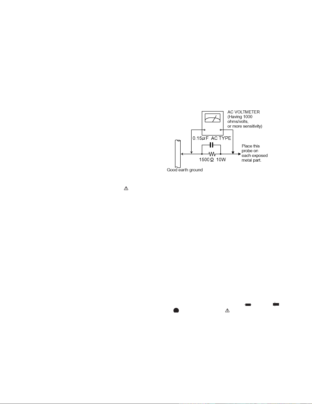
• Alternate check method
Plug the AC line cord directly into the AC outlet. Use an AC
voltmeter having, 1,000 ohms per volt or more sensitivity in
the following manner. Connect a 1,500 ohm 10W resistor
paralleled by a 0.15 µF AC-type capacitor between an
SECTION 1
exposed metal part and a known good earth ground.
Measure the AC voltage across the resistor with the AC
voltmeter.
Move the resistor connection to each exposed metal part,
particularly any exposed metal part having a return path to
the chassis, and measure the AC voltage across the resistor.
Now, reverse the plug in the AC outlet and repeat each
measurement. Voltage measured any must not exceed 0.75
V AC (r.m.s.). This corresponds to 0.5 mA AC (r.m.s.).
1.2 Warning
(1) This equipment has been designed and manufactured to
meet international safety standards.
(2) It is the leg al responsibility of the repairer to ensure that
these safety standards are maintained.
(3) Repairs must be made in accordance with the relevant
safety standards.
(4) It is essential that safety critical components a re replaced
by approved parts.
(5) If mains voltage selector is provided, check setting for local
voltage.
1.3 Caution
Burrs formed during molding may be left over on some parts
of the chassis.
Therefore, pay attention to such burrs in the case of preforming repair of this system.
1.4 Critical parts for safety
In regard with component parts appearing on the silk-screen
printed side (parts side) of the PWB diagrams, the parts that are
printed over with black such as the resistor ( ), diode ( )
and ICP ( ) or identified by the " " mark nearby are critical
for safety.
When replacing them, be sure to use the parts o f the same type
and rating as specified by the manufacturer. (Except the JC version)
1-2 (No.22044)
Page 3
1.5 Safety Precautions (U.K only)
(1) This design of this product contains special hardware and many circuits and components specially for safety purposes. For con-
tinued protection, no changes should be made to the original design unless authorized in writing by the manufacturer. Replacement parts must be identical to those used in the original circuits.
(2) Any unautho rised design alterations or additions will void the manufacturer' s guarantee; furthermore the manufacturer cannot
accept responsibility for personal injury or property damage resulting therefrom.
(3) Essential safety critical components are identified by ( ) on the Parts List and by shading on the schematics, and must never
be replaced by parts other than those listed in the manual. Please not e however that many electrical and mechanical parts in
the product have special safety related characteristics. These characteristics are often not evident from visual inspection. Parts
other than specified by the manufacturer may not have the same safety characteristics as the recommended replacement parts
shown in the Parts List of the Service Manual and may create shock, fire, or other hazards.
(4) The leads in the products are routed and dressed with ties, clamps, tubings, barriers and the like to be separated from live parts,
high temperature parts, moving parts and/or sharp edges for the prevention of electric shock and fire hazard. When service is
required, the original lead routing and dress should be observed, and it shoul d be confirmed that they have been returned to
normal, after re-assembling.
1.5.1 Warning
(1) Service should be performed by qualified personnel only.
(2) This equipment has been designed and manufactured to meet international safety standards.
(3) It is the legal responsib ility of the repairer to ensure that these safety standards are maintained.
(4) Repairs must be made in accordance with the relevant safety standards.
(5) It is essential that safety critical components are replaced by approved parts.
(6) If mains voltage selector is provided, check setting for local voltage.
UX-H33
Burrs formed during molding may be left over on some parts of the chassis. Therefore,
pay attention to such burrs in the case of preforming repair of this system.
(No.22044)1-3
Page 4
UX-H33
1.6 Preventing static electricity
Electrostatic discharge (ESD), which occurs when static electricity stored in the body, fabric, etc. is discharged,
can destroy the laser diode in the traverse unit (optical pickup). Take care to prevent this when performing repairs.
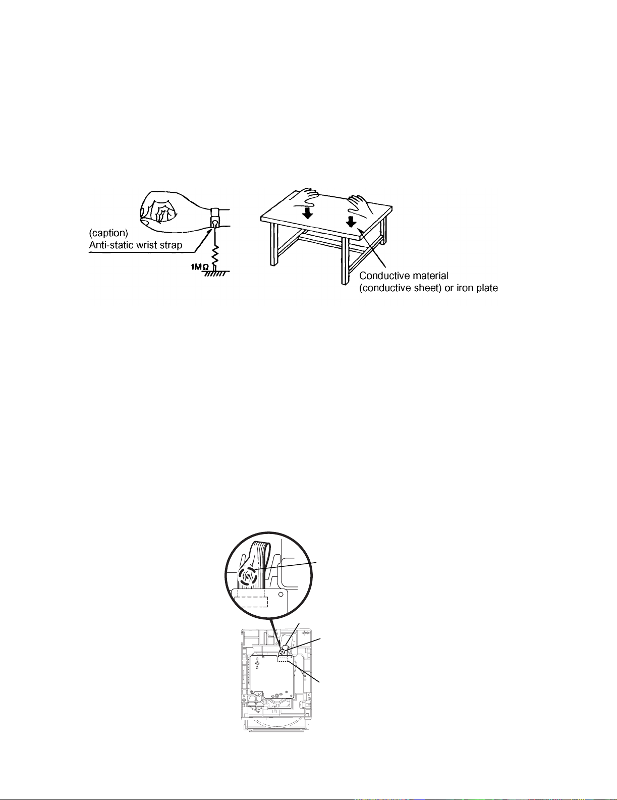
1.6.1 Grounding to prevent damage by static electricity
Static electricity in the work area can destroy the optical pickup (laser dio de) in devices such as CD players.
Be careful to use proper grounding in the area where repairs are being performed.
(1) Ground the workbench
Ground the workbench by laying conductive material (such as a conductive sh eet) or an iron plate over it before placing the
traverse unit (optical pickup) on it.
(2) Ground yourself
Use an anti-static wrist strap to release any static electricity built up in your body.
(3) Ha ndling the optical pickup
• In order to maintain quality during transport and before instal lation, both sides of the laser di ode on the replacement optica l
pickup are shorted. After replacement, return the shorted parts to their original condition.
(Refer to the text.)
• Do not use a tester to check the condition of the laser diode in the optical pickup. The tester's internal power source can easily
destroy the laser diode.
1.7 Handling the traverse unit (optical pickup)
(1) Do not subject the traverse unit (optical pickup) to strong shocks, as it is a sensitive, complex unit.
(2) Cut off the shorted part of the flexible cable using nippers, etc. after replacing the optical pickup. For specific details, r ef er to the replace-
ment procedure in the text. Remove the anti-static pin when replacing th e traverse unit. Be careful not to take too long a time
when attaching it to the connector.
(3) Handle the flexible cable carefully as it may break when subjected to strong force.
(4) It is not possible to adjust the semi-fixed resistor that adjusts the laser power. Do not turn it.
1.8 Attention when traverse unit is decomposed
*Please refer to "Disassembly method" in the text for the CD pickup unit.
• Apply solder to the short land sections before the flexible wire is disconnected from the connector CN101 on the CD servo board.
(If the flexible wire is disconnected without applying solder, the CD pickup may be destroyed by static electricity.)
• In the assembly, be sure to remove solder from the short land sections after connecting the flexible wire.
Shorting round
1-4 (No.22044)
Flexible wire
Shorting round
CN601 on
mechanism
board
Page 5
1.9 Important for laser products
(1) CLASS 1 LASER PRODUCT
(2) DANGER : Invisi ble laser radiation when open and inter
lock failed or defeated. Avoid direct exposure to beam.
(3) CAUTION : There are no serviceable parts inside the
Laser Unit. Do not disassemble the Laser Unit. Replace the
complete Laser Unit if it malfunctions.
(4) CAUTION : The compact disc p layer uses invisible laser
radiation and is equipped with safety switches which
prevent emission of radiation when the drawer is open and
the safety interlocks have failed or are de feated.
It is dangerous to defeat the safety switches.
UX-H33
(5) CAUTION : If safety switches malfunction, the laser is able
to function.
(6) CAUTION : Use of controls, adjustments or performance of
procedures other than those specified herein may result in
hazardous radiation exposure.
CAUTION
Please use enough caution not to see the beam d irectly
or touch it in case of anadjustment or operation check.
VARNING
Osynlig laserstrålning är denna del är öppnad och spårren är
urkopplad. Betrakta ej strålen.
VARO
Avattaessa ja suojalukitus ohitettaessa olet alttiina näkymättömälle lasersäteilylle. Älä katso säteeseen.
REPRODUCTION AND POSITION OF LABELS
ADVARSEL
Usynlig laserstråling ved åbning, når sikkerhedsafbrydere er
ude af funktion. Undgå udsasttelse for stråling.
ADVARSEL
Usynlig laserstråling ved åpning, når sikkerhetsbryteren er avslott. unngå utsettelse for stråling.
Caution label
(No.22044)1-5
Page 6
UX-H33
A
A
A
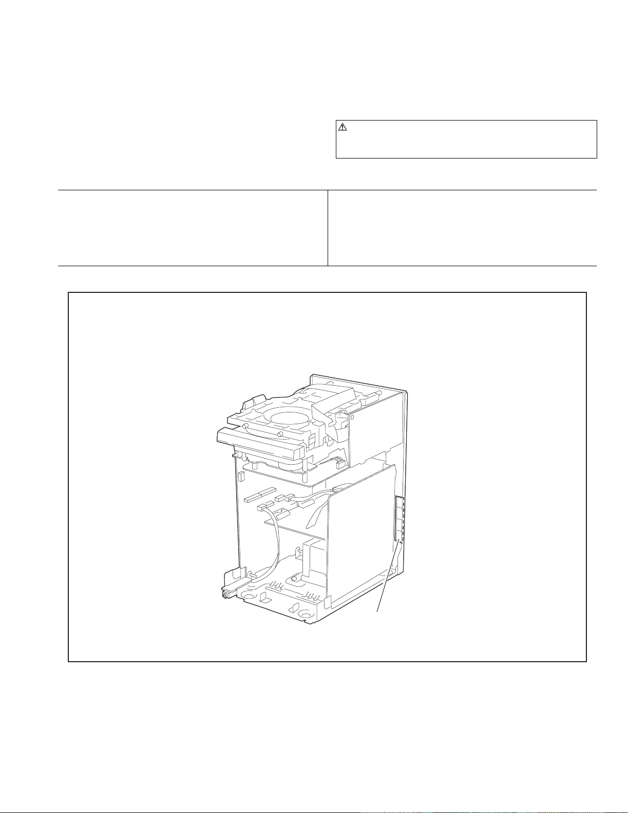
2.1 Main body
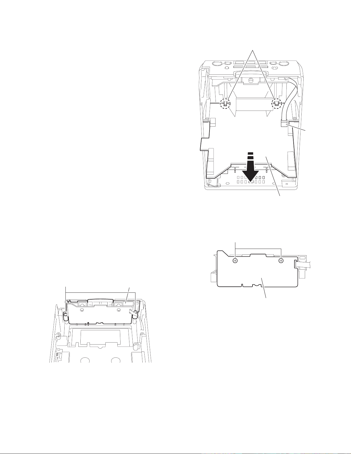
2.1.1 Removing the rear panel
(See Fig.1,2)
(1) From behi nd the body, remove the eight screws A attach-
ing the rear panel.
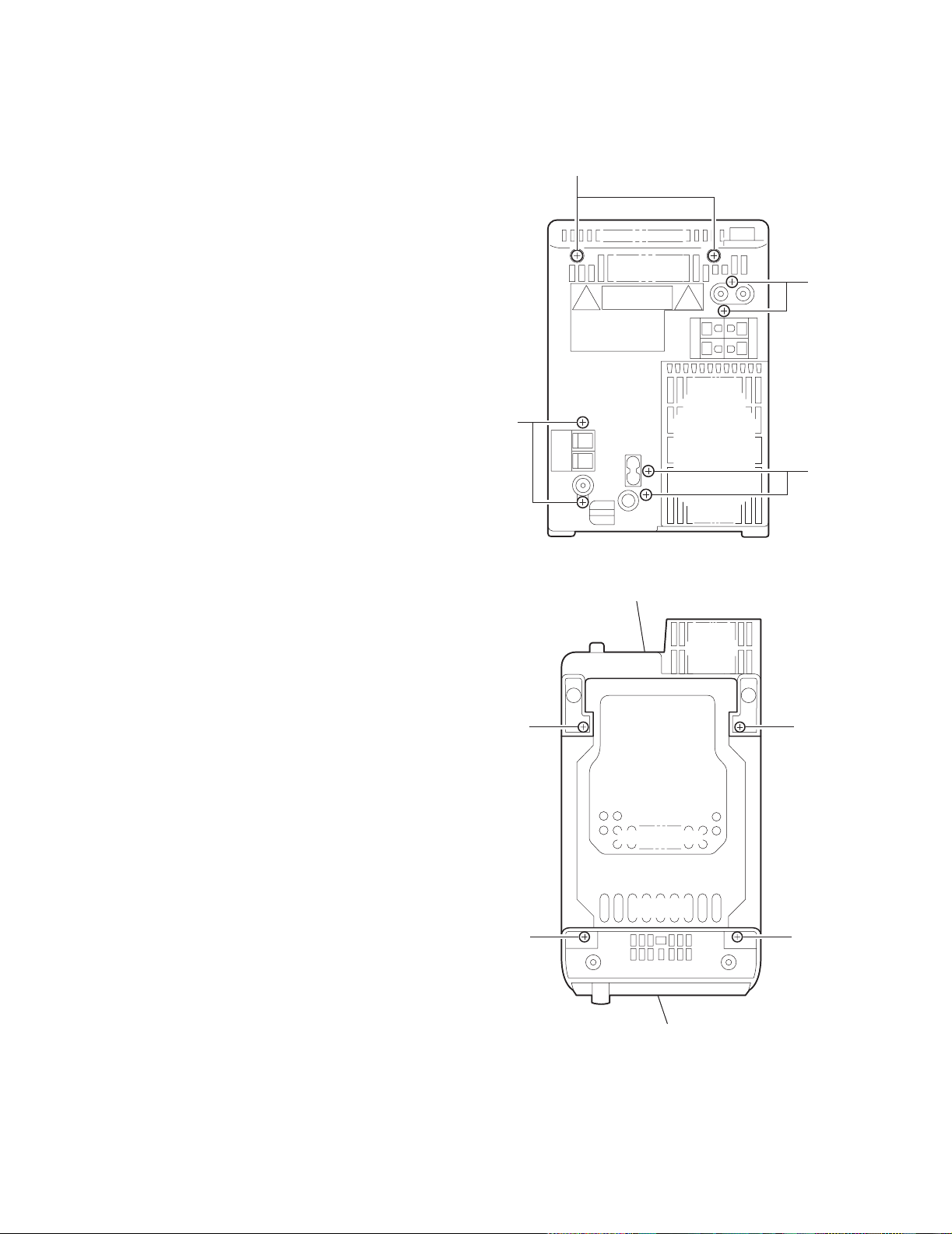
(2) Turing the body upside down, remove the two screws B at-
taching the rear panel, and remove.
SECTION 2
Disassembly method
A
Fig.1
Rear panel
BB
CC
Front panel assembly
Fig.2
1-6 (No.22044)
Page 7
2.1.2 Removning the side pane l (L) and (R)
(See Fig.2~5)
• Prior to performing the following procedure, remove the rear
panel.
(1) Turning the body upside down, remove the two screws C
attaching the front panel assembly.
(2) Turn ing the body initial position, open the CD door while
pressing the upper OPEN button.
(3) Moving the side panel (L) in the arrow direction, remove the
panel from the left side of the body.
(4) Mov ing the side panel (R) in the arrow direction, remove
the panel from the right side of the body.
UX-H33
Side panel (L)
Fig.3
Fig.4
Side panel (R)
Fig.5
(No.22044)1-7
Page 8
UX-H33
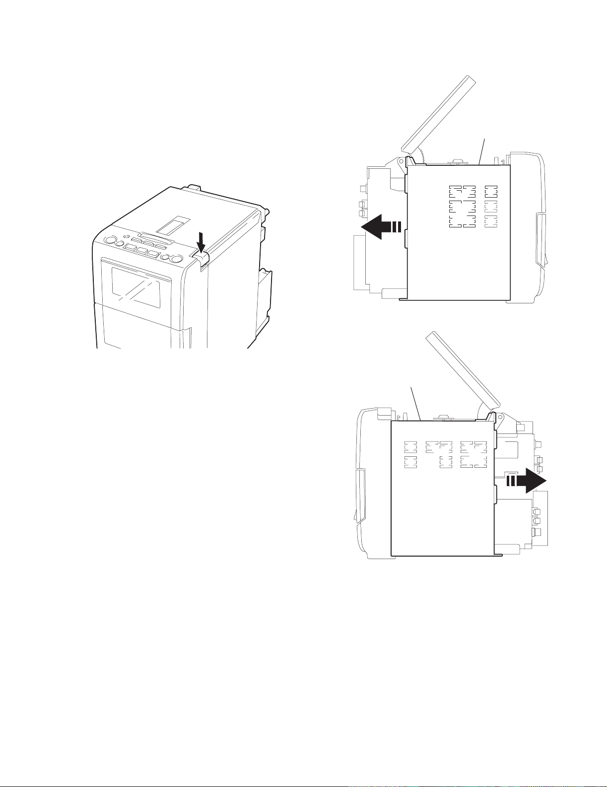
2.1.3 Removing the CD player assembly
(See Fig.6,7)
• Prior to performing the following procedure, remo ve the rear
panel and the left and right side panels.
(1) Disconnect the card wires from the two connectors CN603
and CN604 on the CD servo control board.
(2) Remove the two screws D attaching the front panel assem-
bly on the both sides.
(3) Release the two joints a on the both sides of the front panel
assembly.
(4) Move the CD player assembly in the direction of the arrow .
CD player assembly
a
D
CD servo control board
CN604
CN603
Fig.6
CD player assembly
Fig.7
a
D
1-8 (No.22044)
Page 9
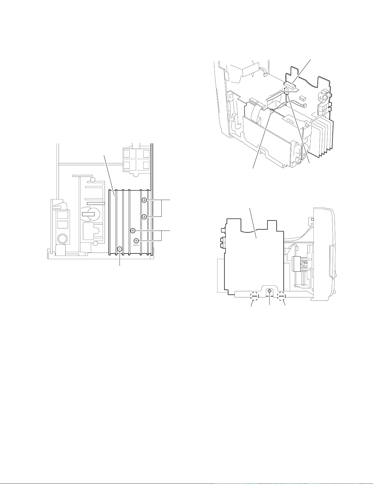
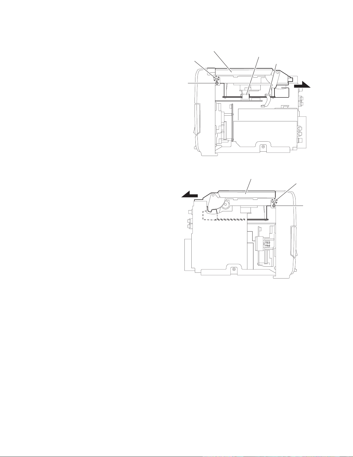
2.1.4 Removing the power amplifier board and he at sin k
(See Fig.8~10)
• Prior to performing the following procedure, remove the rear
panel, the left and right side panels, and the CD player assembly.
(1) Remove the five screws E and F attaching the heat sink.
(2) Disconn ect the wire from connector CN901 on the power
supply board.
(3) Disconnect the card wire from connector CN305 on the
power amplifier board.
(4) Remove the screw G attaching the power amplifier board.
(5) Disconn ect the connector CN301 on the power amplifier
board, and release the two joints b.
REFERENCE:
Remove the screw F, then power amplifier board can be removed without removing heat sink.
Heat sink
UX-H33
Power amplifier board
CN301
Fig.8
F
E
E
Power supply board
CN901
Fig.9
Power amplifier board
bb
G
Fig.10
CN305
(No.22044)1-9
Page 10
UX-H33
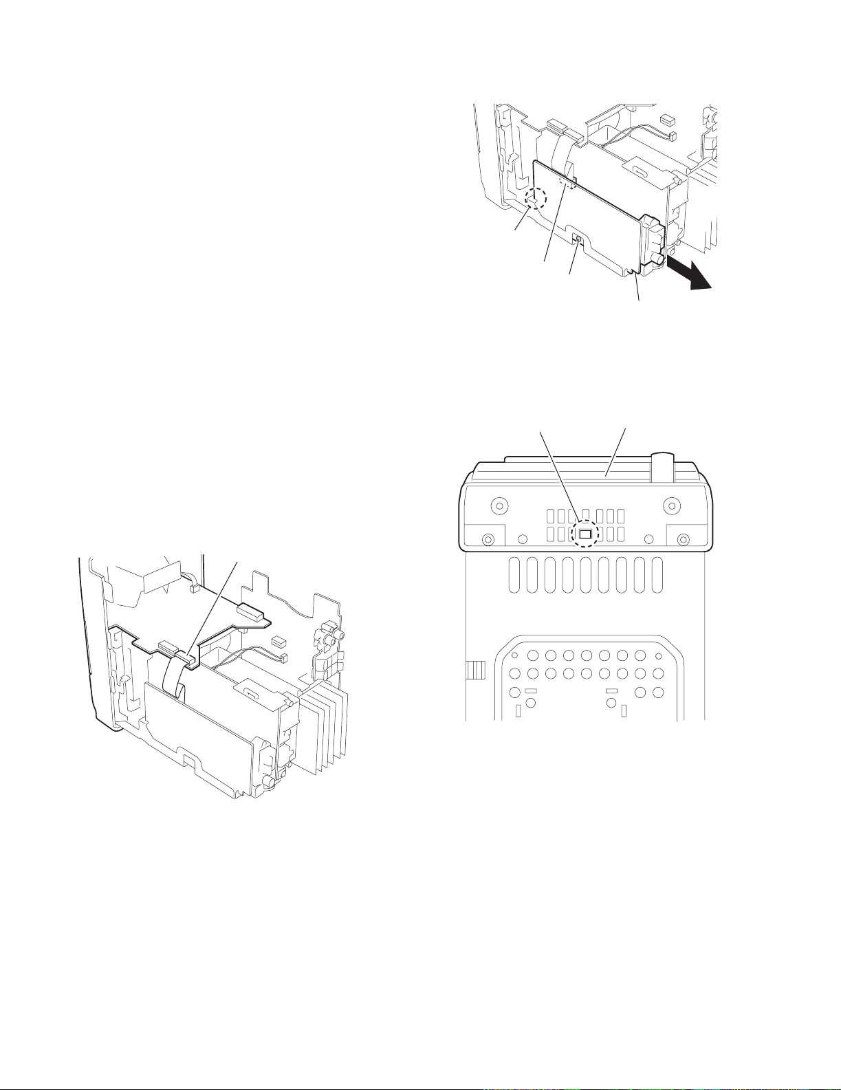
2.1.5 Removing the tuner board
(See Fig.11)
• Prior to performing the following procedure, remo ve the rear
panel, the left and right side panels, and the CD player assembly.
(1) Remove the screw H attaching the tuner board from the
right side of the body.
(2) Disconne ct the card wire from the connector CN1 on the
tuner board.
(3) Release the joint c, and remove the tuner board backward.
2.1.6 Removing the front panel assembly
(See Fig.12,13)
• Prior to performing the following procedure, remo ve the rear
panel the left and right side panels, the CD player assembly,
the power amplifier board.
(1) Disconnect the card wire from the connector CN714 on the
LCD system CPU board.
(2) Release the joint d on the bottom of the front panel assem-
bly using a screwdriver, and remove the front panel assembly toward the front.
c
CN1
H
Tuner board
Fig.11
d
Front panel assembly
LCD system CPU board
CN714
Fig.12
Fig.13
1-10 (No.22044)
Page 11
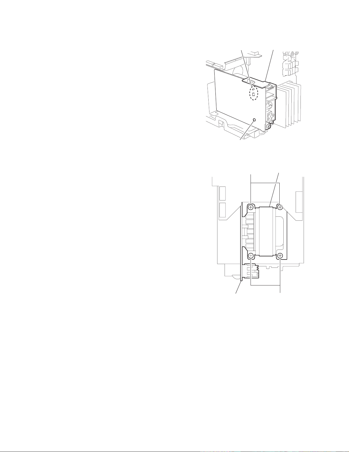
2.1.7 Remove the power transformer an d power supply board
(See Fig.14,15)
• Prior to performing the following procedure, remove the rear
panel, the left and right side panels, the CD player assembly,
the power amplifier board and the tuner board.
(1) Remove the screw I attaching the jack holder and release
joint e, and then remove jack holder.
(2) Remove the four screws J attaching the power transformer
and power supply board.
UX-H33
e
Jack holder
I
Fig.14
Power supply board
J
Fig.15
Power transformer
J
(No.22044)1-11
Page 12
UX-H33
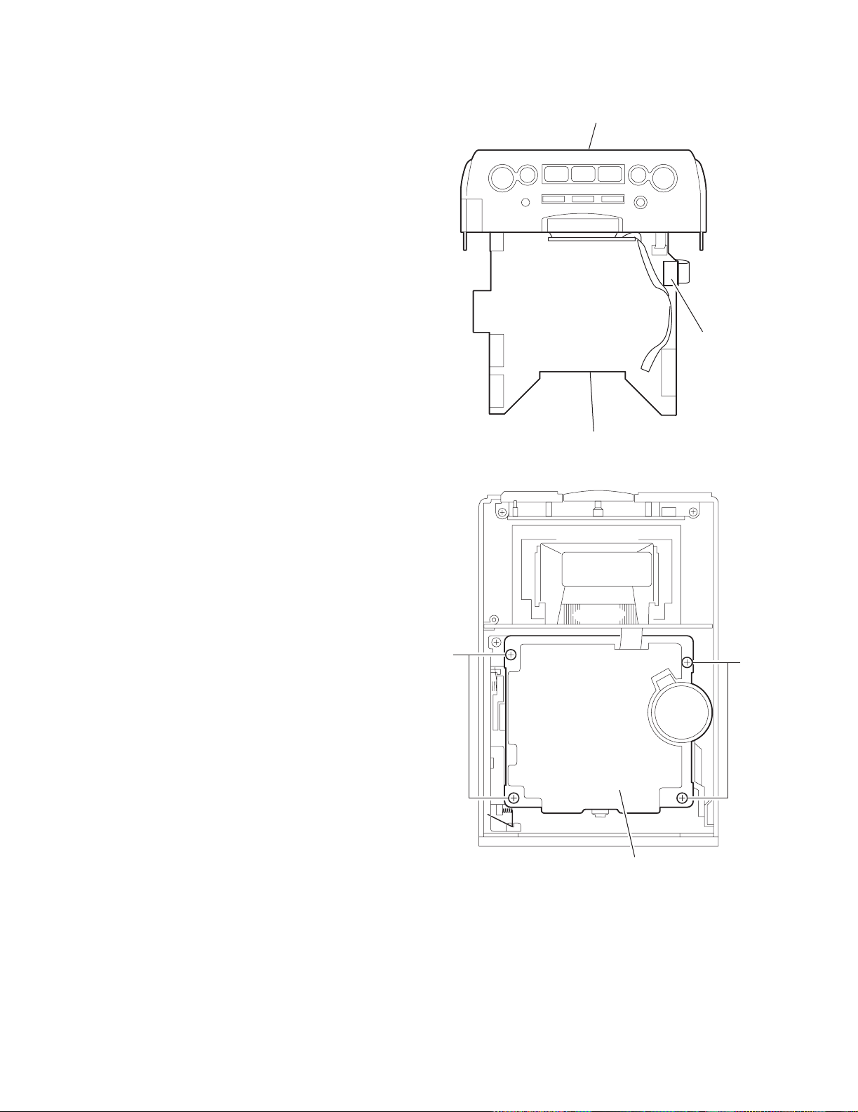
2.1.8 Remove the cassette mechanism assembly
(See Fig.16,17)
• Prior to performing the following procedure, remove the front
panel assembly.
(1) Disconnect the card wire from the connector CN713 on the
LCD system CPU board.
(2) Remove the four screws K and L attaching the cassette
mechanism assembly, and remove.
Front panel assembly
CN713
K
LCD system CPU board
Fig.16
L
1-12 (No.22044)
Cassette mechanism assembly
Fig.17
Page 13
2.1.9 Remove the LCD system CPU board
(See Fig.18)
(1) Disconnect the wire from the connector CN716 on the LCD
system CPU board.
(2) Rele ase the two joints f and pull out the LCD system CPU
board.
UX-H33
f
CN716
2.1.10 Removing the operating switch board
(See Fig.19,20)
• Prior to performing the following procedure, remove the front
panel assembly, the cassette mechanism assembly and the
LCD system CPU board.
(1) Remove th e two screws M attaching the operating switch
button.
(2) Remove the tw o screws N attaching the operating switch
board, and remove.
M
Operating switch button
LCD system CPU board
Fig.18
N
Operating switch board
Fig.20
Fig.19
(No.22044)1-13
Page 14
UX-H33
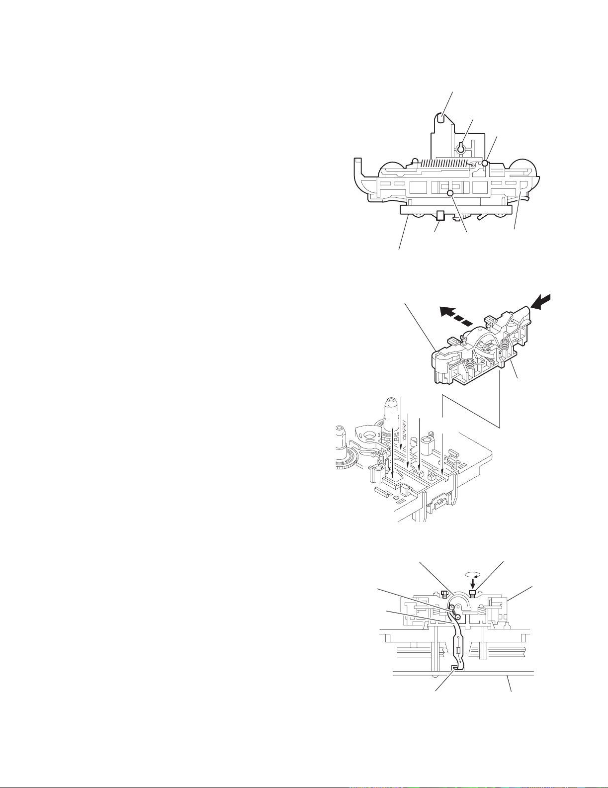
2.2 Cassette mechanism assembly
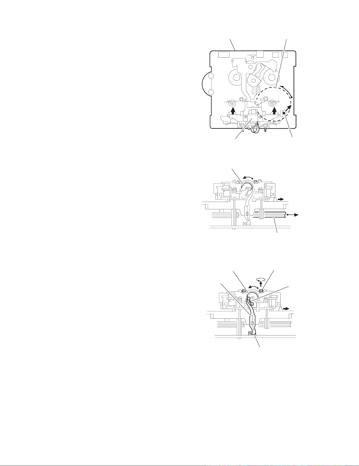
2.2.1 Removing the Play/Record & Clear head
(See Fig.1~3)
(1) While moving the trigger arm o n the right side of the head
mount in the direction of the arrow, turn the flywheel R
counterclockwise until the head mount comes ahead and
clicks.
(2) The head turns counterclockwise a s you turn the fl ywheel
R counterclockwise (See Fig.2 and 3).
(3) Di sconnect the flexible wire from connector CN31 on the
head amplifier & mechanism control board.
(4) Re mo v e the spring from the back of the head.
(5) Loosen the azimuth screw for reversing attaching the head.
(6) Remove the head on the front side of the head mount.
Cassette mechanism assembly
Fig.1
Head
Fly wheelR
Trigger armHead mount
Flexible wire
Fly wheel R
Fig.2
Azimuth screw
Head
for reversing
Spring
CN31
Head amplifer & mecha control board
Fig.3
1-14 (No.22044)
Page 15
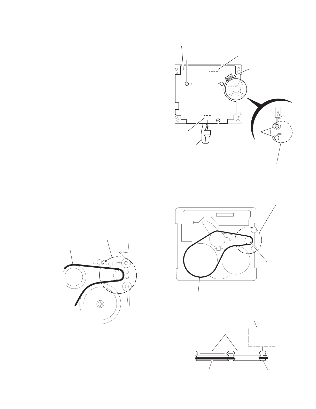
2.2.2 Removing the head amplifier & mechanism control board
(See Fig.4)
(1) Turn over the cassette mechanism assembly and remove
the three screws A attaching the head amplifier & mechanism control board.
(2) Disconn ect the flexible wire from connector CN31 on the
head amplifier & mechanism control board.
(3) Disconnect connector CN32 of the head amplifier & mech-
anism control board from connector CN1 on the reel pulse
board.
REFERENCE:
If necessary, unsolder the 4-pin wire soldered to the main motor.
Head amplifier & mecha control board
AA
CN32
UX-H33
4pin wire
2.2.3 Removing the main motor
(See Fig.4~7)
(1) Remove the two screws B.
(2) Half raise the motor and remove the capstan belt from the
motor pulley.
ATTENTION:
Be careful to keep the capstan belt from grease. When reassembling, refer to Fig.6 and 7 for attaching the capstan belt.
Main motor assembly
Capstan belt
CN31
Flexible wire
A
B
Main motor assembly
Fig.4
Main motor assembly
Motor pulley
Fig.5
Capstan belt
Capstan belt
Fig.6
Main motor assembly
Fly wheel
Motor pulley
Fig.7
(No.22044)1-15
Page 16
UX-H33
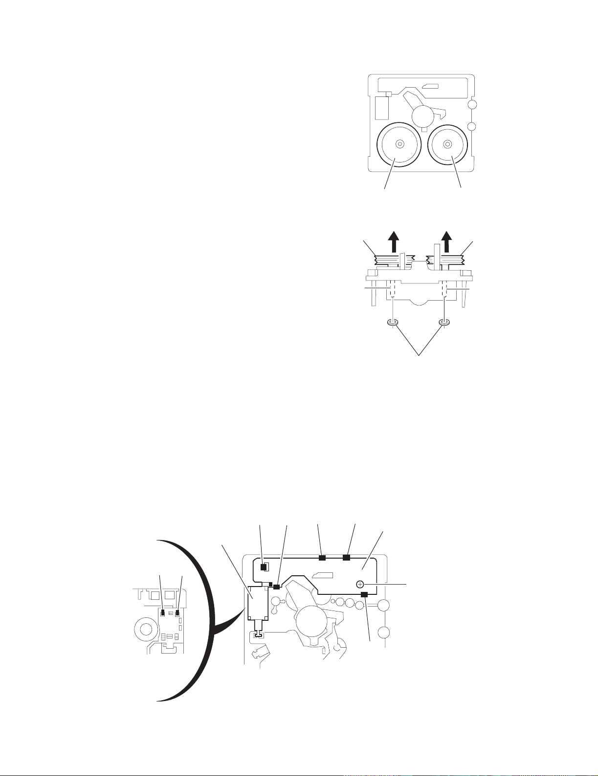
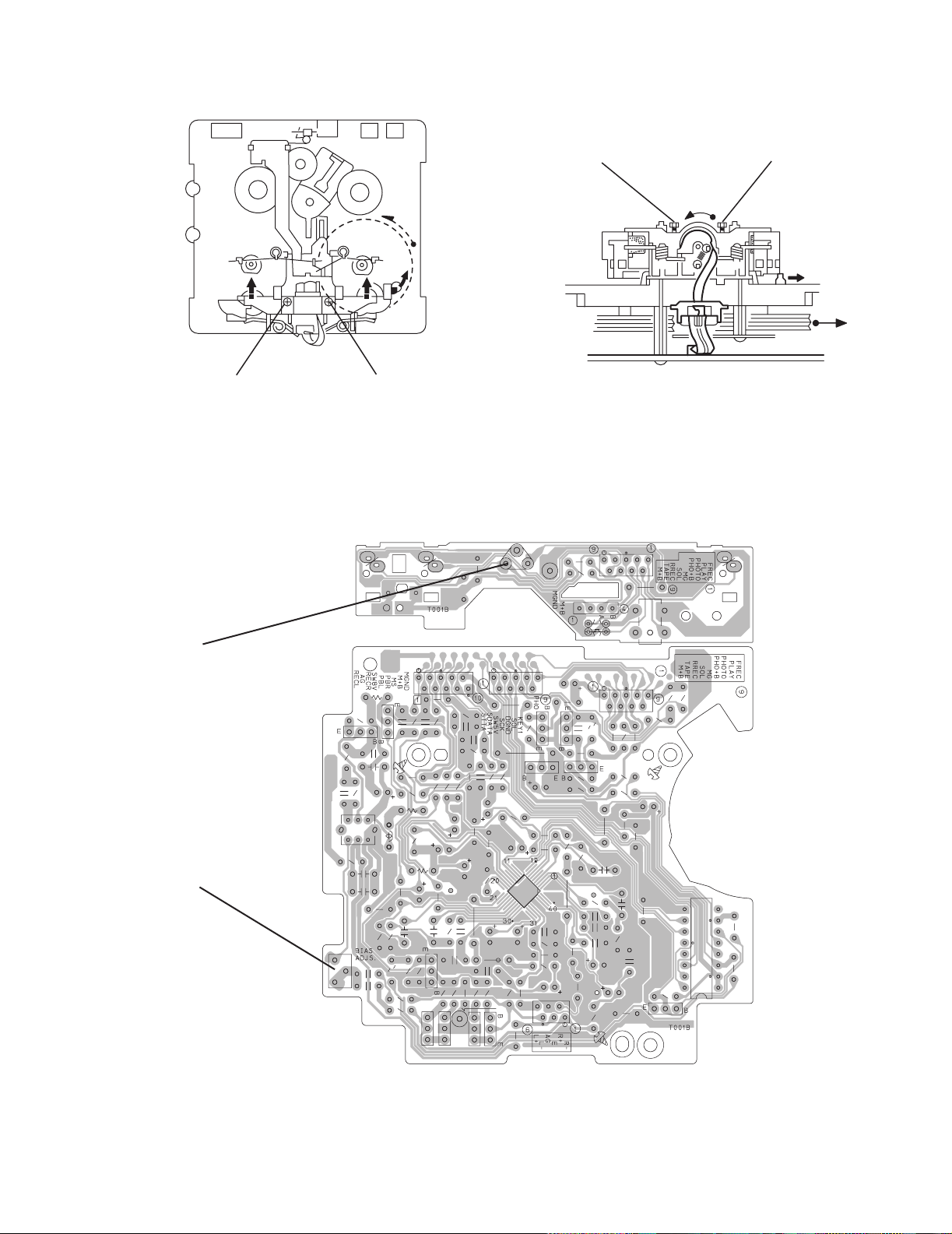
2.2.4 Removing the flywheel
(See Fig.8, 9)
• Prior to performing the following procedure, remove the head
amplifier & mechanism control board and the main motor assembly.
(1) From the front side of the cassette mechanism, remove the
slit washers attaching the capstan shaft L and R. Pull out
the flywheels backward.
Fly wheel R Fly wheel L
Fig.8
2.2.5 Removing the reel pulse board and solenoid
(See Fig.10)
• Prior to performing the following procedure, remove the head
amplifier & mechanism control board.
(1) Remove the screw C.
(2) Re lease the tab a, b, c, d and e reta ining the reel pulse
board.
(3) Re lease the ta b f and g attaching the so lenoid on the reel
pulse board.
(4) The reel pulse board and the solenoid come off.
a
Solenoid
Fly wheel R
Capstan shaft R Capstan shaft L
Slit washer
Fig.9
bc
d
Reel pulse board
Fly wheel L
1-16 (No.22044)
g
f
C
e
Fig.10
Page 17
2.2.6 Reattaching the Play/ Record & Clear head
r
r
(See Fig.11~13)
(1) Reattaching the head mount assembly.
a) Change front of the direction cover of the head mount
assembly to the left (Turn the head forward).
b) Fit the bosses O', P', Q', U' and V' on the head mount
assembly to the holes P and V, the slots O, U and Q
of the mechanism sub assembly (See Fig.11 to 13).
CAUTION:
To remove the head mount assembly, turn the direction cover to the left to disengage the gear. If the
gear can not be disengaged easily, push up the
boss Q' slightly and raise the rear side of the head
mounts slightly to return the direction lever to the
reversing side.
(2) Tig hten the azimuth screw for reversing.
(3) Reattach the spring from the back of the Play / Record &
Clear head.
(4) Connect the flexible wire to connector CN31 on the head
amplifier & mechanism control board.
U' Q'
Head mount assembly
Head mount assembly
O'
Fig.11
P'
P'
V'
V'
Direction cove
UX-H33
O
P
Q
V
Head
Spring
Flexible wire
U
Fig.12
Azimuth screw for reversing
Direction cove
Head mount
CN31
Fig.13
Head amplifier &
mechanism control board
(No.22044)1-17
Page 18

UX-H33
V
3.1 Adjustment method
SECTION 3
Adjustment
Measurement Instruments Required for
Adjustment
1. Low frequency oscillator
This oscillator should have a capacity to output
0dBs to 600 at an oscillation frequency of
50Hz-20kHz.
2. Attenuator impedance : 600
3. Electronic voltmeter
4. Distortion meter
5. Frequency counter
6. Wow & flutter meter
7. Test tape
VT703L : Head azimuth
VT712 : Tape speed and running unevenness
(3kHz)
VT724 : Reference level (1kHz)
8. Blank tape
TYPE : AC-225
TYPE : AC-514
9. Torque gauge : For play and back tension
FWD(TW2111A), REV(TW2121a) and
FF/REW(TW2231A)
10. Test disc: CTS-1000
Measurement conditions
Power supply voltage
AC 230V ~ , 50Hz
Reference output : Speaker : 0.775V/4
: Headphone : 0.077V/32
Reference frequency and
input level ------------------------------ 1kHz, AUX : -8dBs
Measurement output terminal ------- at Speaker J3002
Load resistance --------------------------- 4
Radio Input signal
AM frequency --------------------------------------- 400Hz
AM modulation ---------------------------------------- 30%
FM frequency --------------------------------------- 400Hz
FM frequency deviation ------------------------ 22.5kHz
Tuner section
FM tuning range: 87.5MHz~108.00MHz
AM tuning range: 522kHz~1,629kHz
Voltage applied to tuner +B : DC5.7V
VT : DC 12
Reference measurement
output 26.1mV(0.28V)/3
Input positions AM : Standard loop antenna
FM : TP1 (hot) and TP2 (GND)
Standard measurement position of volume
Function switch to Tape
Beat cut switch to Cut
Super Bass/Active hyper Bass to OFF
Bass Treble to Center
Adjustment of main volume to reference output
VOL : 28
Precautions for measurement
1. Apply 30pF and 33k to the IF sweeper output
side and 0.082 F and 100k in series to the
sweeper input side.
2. The IF sweeper output level should be made as
low as possible within the adjustable range.
3. Since the IF sweeper is a fixed device, there is no
need to adjust this sweeper.
4. Since a ceramic oscillator is used, there is no need
to perform any MIX adjustment.
5. Since a fixed coil is used, there is no need to adjust
the FM tracking.
6. The input and output earth systems are separated.
In case of simultaneously measuring the voltage in
both of the input and output systems with an
electronic voltmeter for two channels, therefore, the
earth should be connected particularly carefully.
7. In the case of BTL connection amp., the minus
terminal of speaker is not for earthing. Therefore, be
sure not to connect any other earth terminal to this
terminal. This system is of an BTL system.
8. For connecting a dummy resistor when measuring
the output, use the wire with a greater code size.
9. Whenever any mixed tape is used, use the band
pass filter (DV-12).
1-18 (No.22044)
Page 19
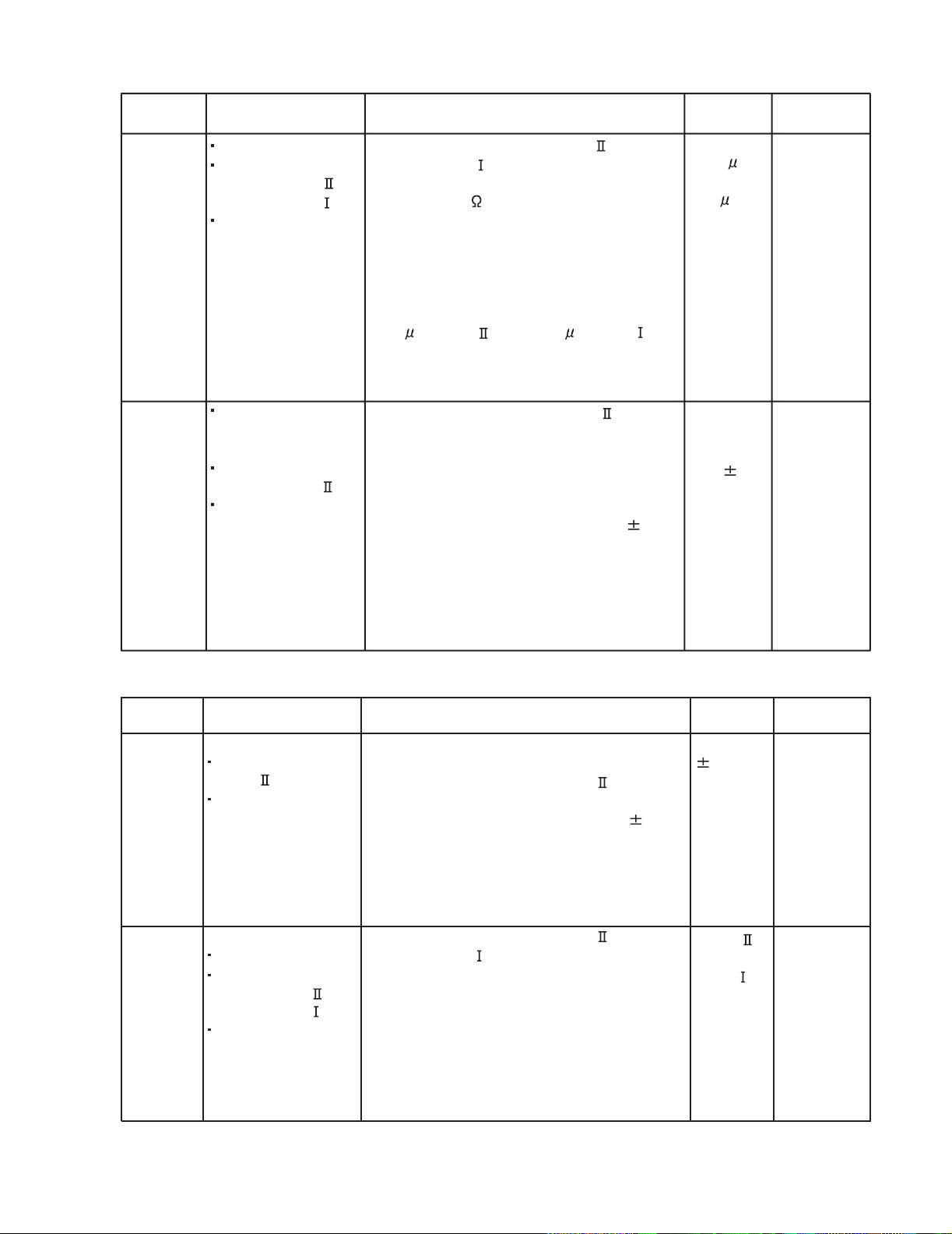
3.2 Cassette mechanism adjustment
UX-H33
Head azinuth
adjustment screw
(Forward side)
Mecha control board
Head azinuth
adjustment screw
(Reverse side)
SW1
SW2
Head azinuth
adjustment screw
(Forward side)
Head azinuth
adjustment screw
(Reverse side)
CN31
R/P head, Erase head
P1
D1
VR37
R371
CN1
FW100
SW5
Motor speed
VR37
BIAS adjust
VR31
C308
R327
VR31
R313
Q302
R315
C316
C319
C221
R314
L301
C121
C314
C313
R104
Q305
D340
C310
R304
R310
C107
L303
R102
R121
R221
R303
R335
R353
R339
R108
C113
R302
Q343
C103
C207
R301
C301
Q342
C304
R208
C105
C205
C106
R306
R106
R101
C104
CN34
C306
Q344
R105
C102
R344
R205
R110
Q345
R345
C307
R336
C340
R346
R206
C206
R107
W1
Q346
R305
C110
R210
C300
C341
R109
R372
Q372
C371
CN33
IC32
R116
C109
CN31
Q371
C101
C374
R216
Q375
R376
C376
R204
R201
C202
C204
C201
CN32
C203
R202
C210
R340
C331
R342
R347
Q347
SW6
R343
R341
IC33
IC1
D375
Q376
R338
R375
R337
C213
C342
C209
W1
R207
(No.22044)1-19
Page 20

UX-H33
3.2.1 Mechanism section
Item Condition Measurement method Ref.value
Head
azimuth
Test tape
: VT703L (8kHz)
Output terminal
: Speaker out
1.Playback the test tape VT703L (8kHz).
2.Adjust to maximum output level by azimuth
adjustment screw for forward side and reverse
side.
Maximum
output
3.This adjustment is adjust by adjustment screw
of forward side and adjustment screw of reverse
side.
Tape speed
Test tap
: VT712 (3kHz)
Output terminal
Playback the test tape VT712 (3kHz) at end of
forward side,adjust to 2,940~3,90Hz indication
of frequency counter by VR37.
2,940 ~
3,090Hz
: Speaker out or
Headphone out
Adjustment
position
Only adjust
at changed
head
VR37
Item Condition Measurement method Ref.value
Tape speed
diviation at
FWD/REV
Test tape
: VT712 (3kHz)
Output terminal
Playback the test tape VT712 (3kHz) at end
of forward and reverse, tape speed deviation
should be less than 6.0Hz.
Leass than
6.0Hz
: Speaker out or
Headphone out
Wow & Flutter Playback the test tape VT712 (3kHz) at
Test tape
: VT712 (3kHz)
Output terminal
start of forward and reverse,Wow & Flutter
are should be less than 0.25%(WRMS).
Less than
0.25%
(WRMS)
: Speaker out or
Headphone out
Adjustment
position
VR31
1-20 (No.22044)
Page 21
3.2.2 Electrical adjustment
UX-H33
Item Condition Measurement method Ref.value
Recording
BIAS
adjustment
Forward or Reverse
Test tape
:AC-514 TYPE
:AC-225 TYPE
Output terminal
Recording head
1.Set the test tape(AC-514 TYPE and
AC-225 TYPE ), then make REC/PAUSE
condition.
2.Connect 100 to recording head by series,
then connect to VTVM for measurement the
current.
AC-225
:4.20 A
AC-514
:4.0 A
3.After setting, start the recording by release
the PAUSE, in this time bias current adjust
to next fig. by VR31 for Lch and VR32 for
Rch.
4.0 A (TYPE ) and 4.20 A (TYPE ).
R/P
playback
frequency
response
Reference frequency
: 1kHz / 10kHz
(Reference: -20dB)
Test tape
: AC-514 TYPE
Input terminal
: OSC IN
1.Set the test tape (AC-514 TYPE ), then
make REC/PAUSE condition.
2.Release the PAUSE, then start recording
the 1kHz and 10kHz of reference frequency
from oscillator.
3.Playback the recorded position, 1kHz and
10kHz output deviation should -1dB 2dB
Output
deviation
1kHz/10kHz
:-1dB 2dB
to readjust by VR31 for Lch and VR32 for
Rch.
Adjustment
position
VR31
VR31
3.2.3 Electrical response confirmation
Item Condition Measurement method Ref.value
Recording
bias
current
Forward or Reverse
Test tape
: TYPE (AC-514)
Measurement
terminal
: BIAS test point on
printed circuit board
Erase
current
(reference
value)
Forward or Reverse
Rec condition
Test tape
: AC-514 TYPE
: AC-225 TYPE
Measurement
terminal
: Both side of Erase
head
1.Change BIAS1 and 2, confirm the frequency
should be change.
2.Set the test tape (AC-514 TYPE ), then
make REC/PAUSE condition.
3.Confirm the frequency should 100Hz 6kHz
at BIAS test point on printed circuit board.
1.Set the test tape (AC-514 TYPE and
AC-225 TYPE ), then make REC/PAUSE
condition.
2.Release the PAUSE to REC condition,
connect 1W to ERASE head by series, then
confirm the erase current at both side of
erase head.
Adjustment
position
100 kHz
6 kHz
TYPE
: 120 mA
TYPE
: 75 mA
(No.22044)1-21
Page 22
UX-H33
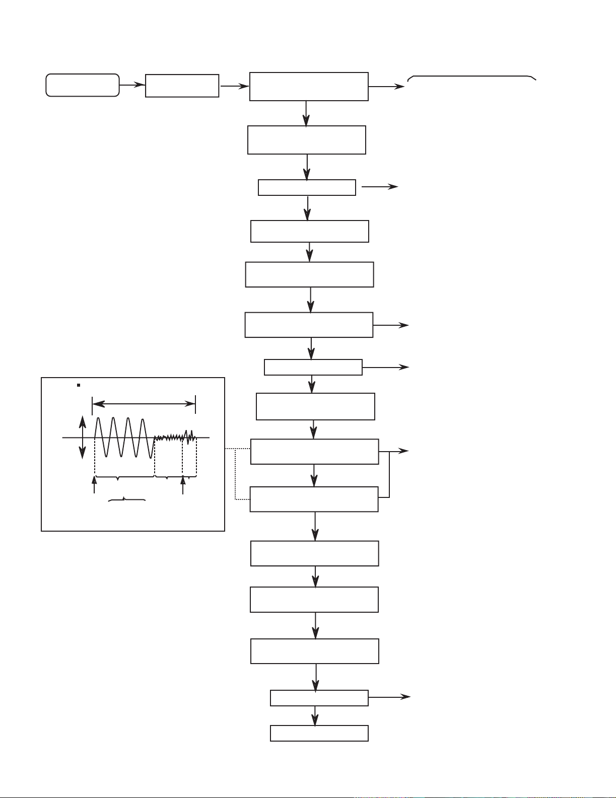
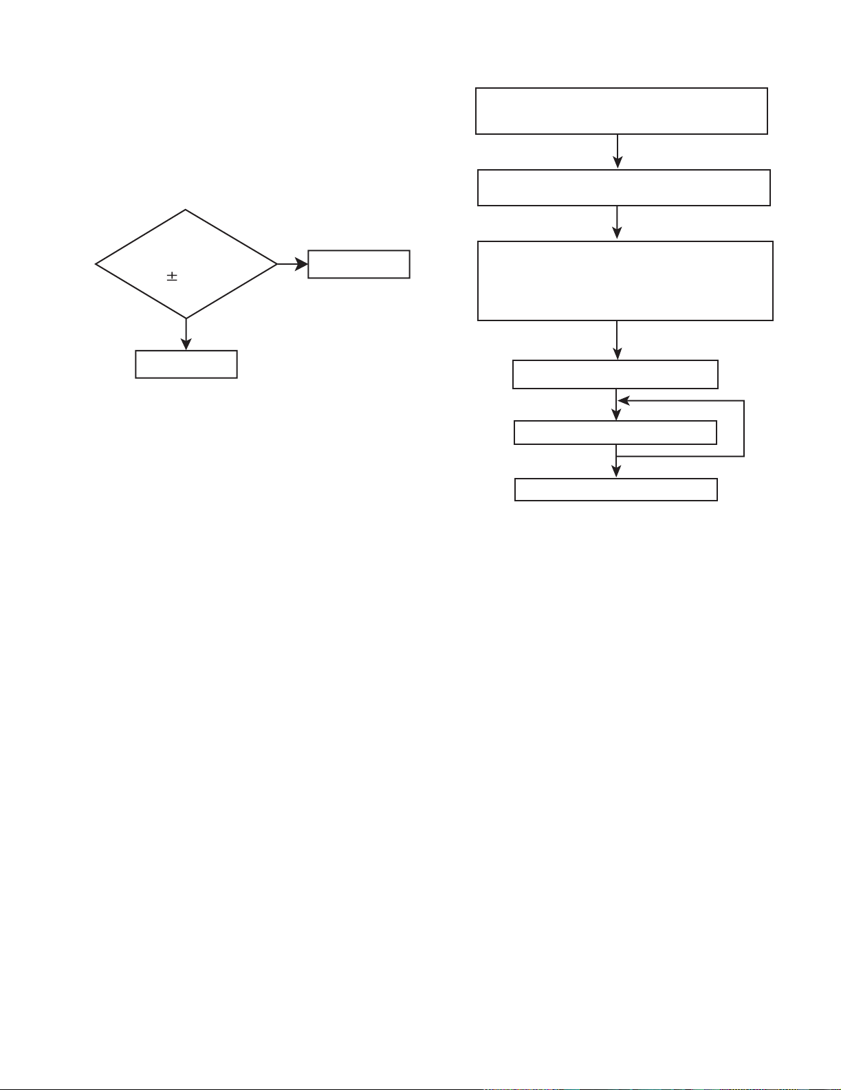
3.3 Flow of functional operation until TOC read (CD)
Power ON
Power Key
Slider turns REST
SW ON.
Automatic tuning
of TE offset
Check Point
Check that the voltage at the pin4
of CN601 is 0V (a moment)?
VREF
Tracking error waveform at TOC reading
pin 20 of
IC601(TE)
Approx
1.8V
Tracking
servo
Disc statas
to rotate
off statas
Automatic measurement
of TE amplitude and
automatic tuning of
TE balance
Approx.3sec
Tracking
servo
on statas
Disc to be
braked to stop
TOC reading
finishes
500mv/div
2ms/div
Fig.1
Laser ON
Detection of disc
Automatic tuning of
Foucus offset
Automatic measurement of
Focus A-curve amplitude
Disc is rotated
Focus servo ON
(Tracking servo ON)
Automatic measurement of
Tracking error amplitude
Automatic tuning of
Tracking error balance
Check that the voltage at the
pin2 of IC601 is 0V?
Confirm that the Focus error
S-cuve siganl at the pin23 of
IC601 is approx.2Vp-p
Confirm that the siganl from
pin22 IC603 is 0V as a
accelerated pulse during
approx.400ms.
Confirm the waveform of
the Tracking error signal
at the pin20 of IC601
(See fig-1)
1-22 (No.22044)
Automatic tuning of
Focus error balance
Automatic tuning of
Focus error gain
Automatic tuning of
Tracking error gain
TOC reading
Play a disc
Confirm the eys-pattern
at the lead of TP1
Page 23
UX-H33
3.4 Maintenance of laser pickup (CD)
(1) Cleaning the pick up lens
Before you replace the pick up, please try to clean the lens
with a alcohol soaked cotton swab.
(2) Life of the laser diode
When the life of the laser diode has expired, the following
symptoms will appear.
• The level of RF output (EFM output : amplitude of eye
pattern) will below.
Is the level of
RFOUT under
NO
Replace it.
1.25V 0.22Vp-p?
YES
O.K
(3) Semi-fixed resistor on the APC PC board
The semi-fixed resistor on the APC printed circuit board
which is attached to the pickup is used to adjust the laser
power. Since this adjustment should be performed to
match the characteristics of the whole optical block, do not
touch the semi-fixed resistor.
If the laser power is lower than the specified value, the laser diode is almost worn out, and the laser pickup should
be replaced.
If the semi-fixed resistor is adjusted while the pickup is
functioning normally, the laser pickup may be damaged
due to excessive current.
3.5 Replacement of laser pickup (CD)
Turn off the power switch and, disconnect the
power cord from the ac outlet.
Replace the pickup with a normal one.(Refer
to "Pickup Removal" on the previous page)
Plug the power cord in, and turn the power on.
At this time, check that the laser emits for
about 3seconds and the objective lens moves
up and down.
Note: Do not observe the laser beam directly.
Play a disc.
Check the eye-pattern at TP1.
Finish.
(No.22044)1-23
Page 24
UX-H33
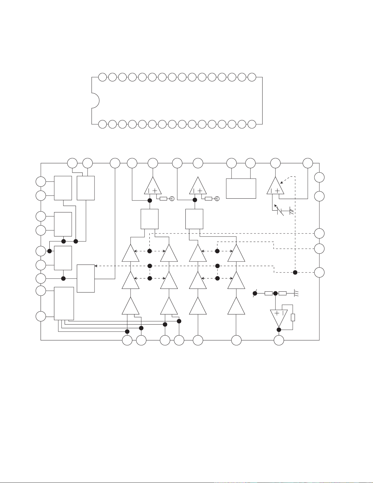
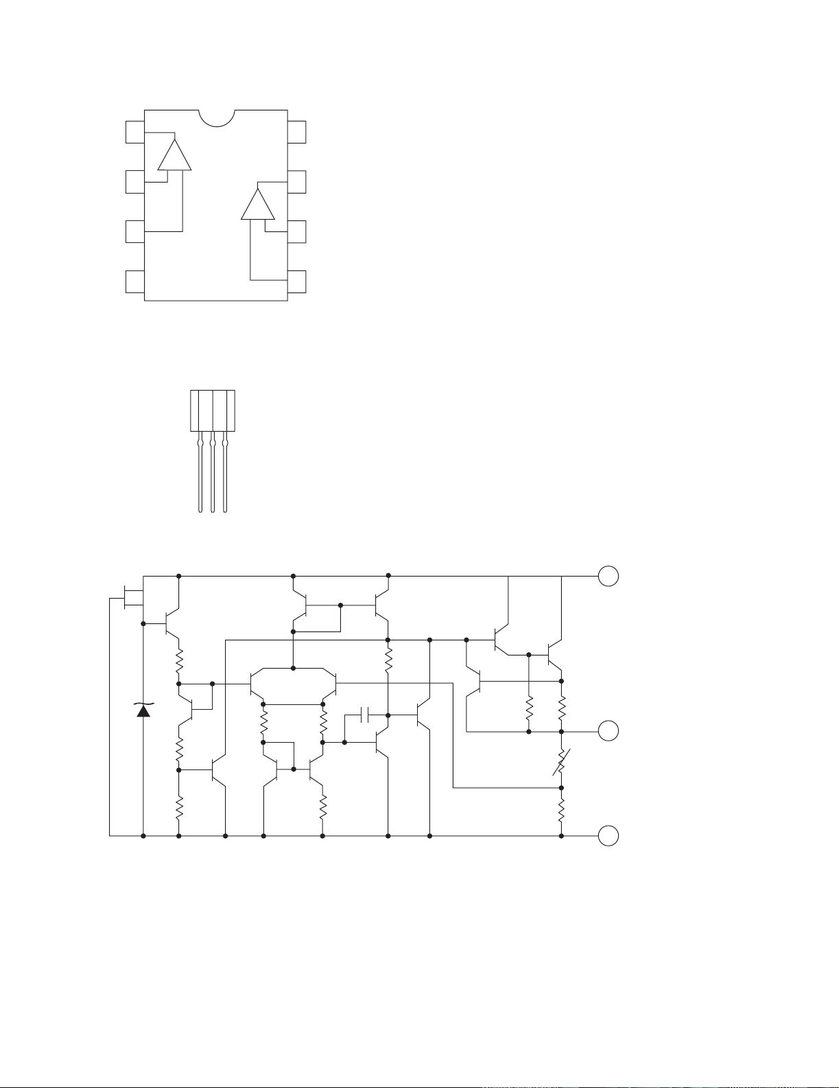
4.1 AN22000A-W (IC601) : RF & SERVO AMP
• Terminal layout
12345678910111213141516
• Block diagram
SECTION 4
Description of major ICs
17181920212223242526272829303132
OFTR
COFTR
12
BDO
11
BCDO
ARF
CAGC
RFIN
RFOUT
RFN
13 14
8
7
56
4
CEA
9
BDO OFTR
AGC
RF_EQ
NRFDET3TOUT
10
3TENVNRFDET
15
FEN
GCA BCA
AMP
22
FEOUT
23
SUBT
TEN
GCA BCA
AMP
21
20
SUBT
GCA BCA
AMP
19
VDET
GCA BCA
AMP
18
PDLDVDETTEBPFTEOUT
2
1
3
16252624
GCTL TBAL FBAL GND VCC
1-24 (No.22044)
32
31
A
C
30
29
B
D
27
E
28
F
17
VREF
Page 25
• Pin function
Pin
Symbol I/O Function
No.
1 PD I APC Amp. input terminal
2 LD O APC Amp. output terminal
3 VCC - Power supply terminal
4 RFN I RF adder Amp. inverting input terminal
5 RFOUT O RF adder Amp. output terminal
6 RFIN I AGC input terminal
7 CAGC I Input terminal for AGC loop filter capacitor
8 ARF O AGC output terminal
9 CEA I Capacitor connecting terminal for HPF-
Amp.
10 3TOUT O 3 TENV output terminal
11 CBDO I Capacitor connecting terminal for envelope
detection on the darkness side
12 BDO O BDO output terminal
13 COFTR I Capacitor connecting terminal for envelope
detection on the light side
14 OFTR O OFTR output terminal
15 NRFDET O NRFDET output terminal
Pin
Symbol I/O Function
No.
16 GND - Ground
17 VREF O VREF output terminal
18 VDET O VDET output terminal
19 TEBPF I VDET output terminal
20 TEOUT O TE Amp. output terminal
21 TEN I TE Amp. inverting input terminal
22 FEN I FE Amp. inverting input terminal
23 FEOUT O FE Amp. output terminal
24 GCTL O GCTL & APC terminal
25 FBAL O FBAL control terminal
26 TBAL O TBAL control terminal
27 E I Tracking signal input terminal 1
28 F I Tracking signal input terminal 2
29 D I Focus signal input terminal 4
30 B I Focus signal input terminal 3
31 C I Focus signal input terminal 2
32 A I Focus signal input terminal 1
UX-H33
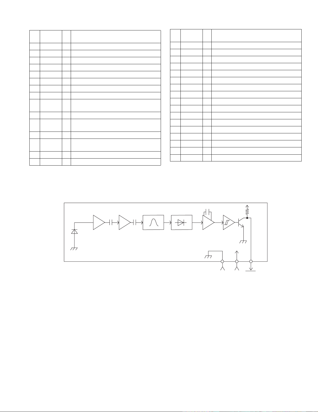
4.2 GP101UM281YK (IC750) : Remocon receiver
• Block diagram
Amp Limiter B.P.F
Demodulator Integrator
GND VCC Vout
RL
Cornparator
(No.22044)1-25
Page 26
UX-H33
4.3 HA12238F (IC32) : R/P Equalizer
• Pin layout
PB-NF1(L)
TEST 2
RIP
PBIN(l)
REC Return
GND
PBIN(R)
NC
TEST 3
PB-NF1(R)
31
32
33
34
35
36
37
38
39
40
PB-NF2(L)
PB-EQ(L)
30
29
+
Return SW
Return SW
+
-
EQ OUT(L)
TAI(L)
28
27
MUTE
MUTE
NC
PB OUT(L)
26
25
REC IN(L)
ALC(L)
24
23
NC
22
EQ
EQ
REC OUT(L)
21
ALC
TEST
20
(Open for nomal use)
19
Iraf
18
GND
ALC DET
17
16
Vcc
REC MUTE OFF/ON
15
MUTO ON/OFF
14
REC RETURN ON/OFF
13
TEST 4
12
ALC ON/OFF
11
1
2
PB-EQ(R)
PB-NF2(R)
3
4
TAI(R)
EQOUT(R)
5
6
NC
PB OUT(R)
7
8
ARC(R)
REC IN(R)
9
10
NC
REC OUT(R)
1-26 (No.22044)
Page 27

• Pin function
Pin No. Symbol Function
1 PB-NF2(R) PB EQ feed back
2 PB-EQ(R) NAB output
3 EQOUT(R) EQ output
4 TAI(R) Tape input
5 PBOUT(R) PB output
6 NC NC pin
7 REC IN(R) REC-EQ input
8 ALC(R) ALC(R) signal out put
9 NC NC pin
10 REC OUT(R) REC output
11 ALC ON/OFF Mode control input
12 TEST4 TEST pin
13 REC Return ON/OFF Mode control input
14 MUTE ON/OFF Mode control input
15 REC Return ON/OFF Mode control input
16 Vcc Vcc Pin
17 ALC DET ALC detection signal out put
18 GND GND pin
19 I REF Equalizer reference current input
20 Test mode Test modepin
21 REC OUT(L) REC output
22 NC NC pin
23 ALC(L) ALC(L) signal out put
24 REC IN(L) REC-EQ input
25 NC NC pin
26 PBOUT(L) PB output
27 TAI(L) Tape input
28 EQOUT(L) EQ output
29 PB-EQ(L) NAB output
30 PB-NF2(L) PB EQ feed back
31 PB-NF1(L) PB EQ feed back
32 TEST2 TEST pin
33 RIP Ripple fillter
34 PBIN(L) PB input
35 REC-RETURN REC Return
36 GND GND pin
37 PBIN(R) PB input
38 NC NC pin
39 TEST3 TEST pin
40 PB-NF1(R) PB EQ feed back
UX-H33
(No.22044)1-27
Page 28
UX-H33
4.4 HA17758A (IC301) : Dual operational amp
• Pin layout
Vout1
Vin(-)1
Vin(+)1
VEE
4.5 KIA78S05P-T (IC604) : Regulater
• Pin layout
1
1
- +
2
3
4
2
+ -
8
7
6
5
VCC
Vout2
Vin(-)2
Vin(+)2
• Block diagram
Z1
Q14
R9
R10
R11
Q1
Q16
R1
Q7 Q8
Q2
Q3 Q5
Q4
Q6
R2
R3
C1
R4
Q9
Q10
Q11
Q12
R8
3 INPUT
Q13
R7
1 OUTPUT
R5
R6
2 COMMON
1-28 (No.22044)
Page 29
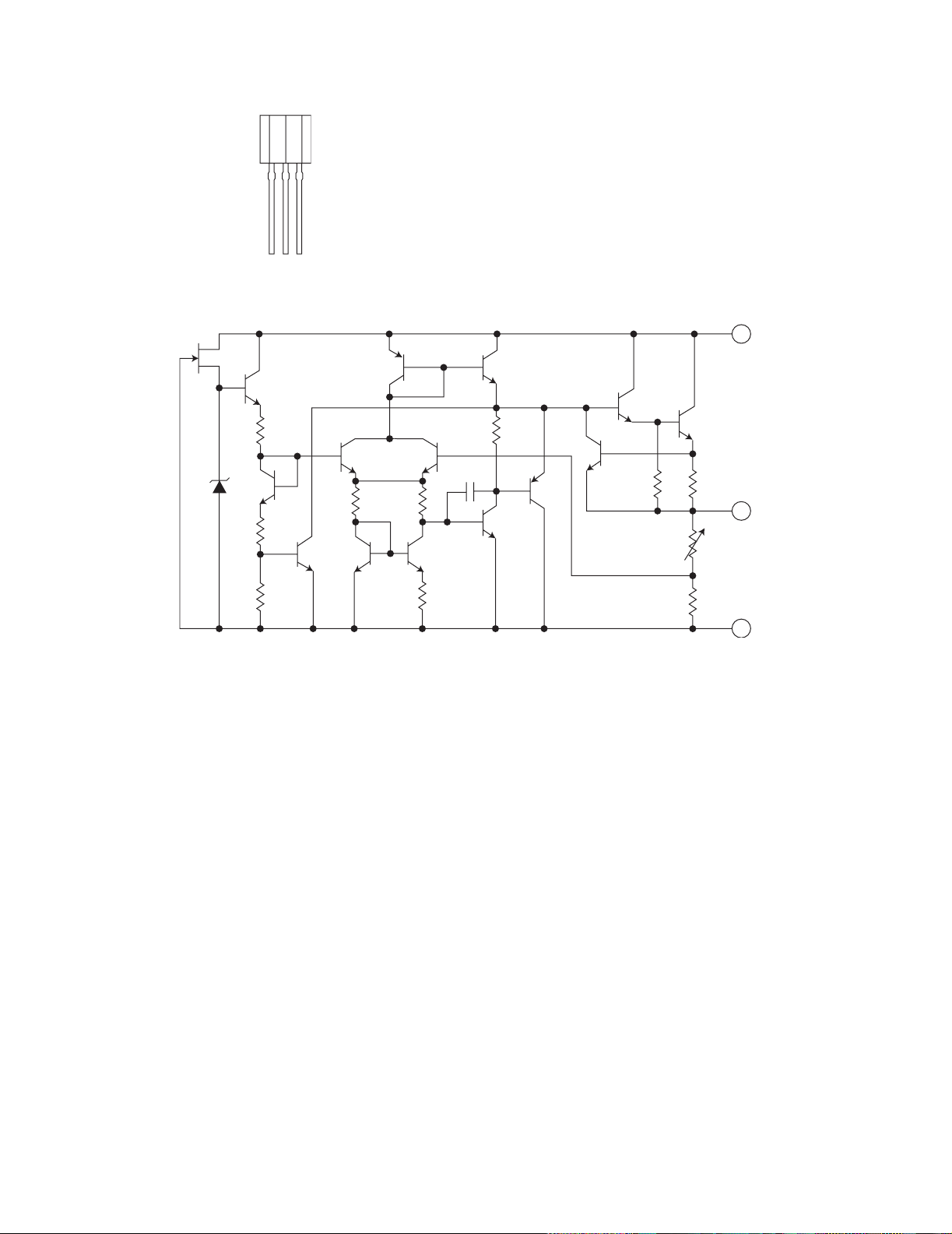
4.6 KIA78S06P-T (IC932) : Regulator
•Pin layout
1 2 3
• Block diagram
UX-H33
3 INPUT
Z1
Q14
R9
Q16
Q1
R11 R10
R1
Q2 Q7
Q4
Q3
Q6
R3
R2
Q8
C1
Q5
R4
Q9
Q10
Q11
Q12
R8
Q13
R7R5R6
1 OUTPUT
2 COMMON
(No.22044)1-29
Page 30
UX-H33
4.7 LA1838 (IC1): FM AM IF amp & Detector, FM MPX decoder
• Block Diagram
30
ALC
BUFF
FM
S-METER
FM IF
1
29
AM
OSC
S-CLRVE
PM
DET
2
28
REG
AM
MIX
SD
COMP
AM/FM
IF-BUFF
3
27
FM
RF.AMP
AM IF
4
26
AGC
AM
S-METER
GND
25
24
DET
TUNING
DRIVE
5
6
STEREO
DRIVE
7
22
23
P-DET
VCC
89
VCO
384KHz
21
DECODER
ANIT-BIRDIE
STEREO
5N
SW
10
20
FF
38k
11
18
19
MUTE
FF
/
19k
2
12 13
FF
19k
17 16
/LS
14
PILOT
DET
15
• Pin Function
Pin No. Symbol I/O Function
1 FM IN I This is an input terminal of FM IF signal.
2 AM MIX O This is an out put terminal for AM mixer.
3 FM IF I Bypass of FM IF
4 AM IF I Input of AM IF Signal.
5 G ND - This is the device ground terminal.
6
7
TUNED
STEREO
O When the set is tunning, this terminal becomes "L".
O Stereo indicator output. Stereo "L", Mono: "H"
8 VCC - This is the power supply terminal.
9 FM DET - FM detect transformer.
10 AM SD - This is a terminal of AM ceramic filter.
11 FM VSM O Adjust FM SD sensitivity.
12 AM VSM O Adjust AM SD sensitivity.
13 MUTE I/O When the signal of IF REQ of IC121(LC72131) appear, the signal of FM/AM IF output. //Muting
control input.
14
15
FM/AM
MONO/ST
I Change over the FM/AM input. "H" :FM, "L" : AM
O Stereo : "H", Mono: "L"
16 L OUT O Left channel signal output.
17 R OUT O Right channel signal output.
18 L IN I Input terminal of the Left chan nel post AMP.
19 R IN I Input terminal of the Right channel post AMP.
20 RO O Mpx Right channel signal output.
21 LO O Mpx Left channel signal output.
22 MPX IN I Mpx input terminal
23 FM OUT O FM detection output.
24 AM DET O AM detection output.
25 AM AGC I This is an AGC voltage input terminal for AM
26 AFC - This is an output terminal of voltage for FM-AFC.
27 AM RF I AM RF signal input.
28 REG O Register value between pin 26 and pin 28 besides the frequency width of the input signal.
29 AM OSC - This is a terminal of AM Local oscillation circuit.
30 OSC BUFFER O AM Local oscillation Signal output.
1-30 (No.22044)
Page 31

4.8 LA4663 (IC300) : 2ch power amp
•Pin layout
• Block diagram
UX-H33
+5V
4.7
10V
22K
- +
SIGNAL
MUTE
+
10
10V
IN1
PRE
GND
STAND BY
6
2
Ri=
20k
3
+5V
5
Input Amp
78
VCC1 VCC2
CH 1
+
Output Amp
-
OUTPUT-GND SHORT
OUTPUT-VCC SHORT
RL SHORT
THERMAL SHUTDOWN
PROTECTION CIRCUITS
+OUT1
PWR
GND1
-OUT1
14
0.1
2.2
13
2.2
0.1
12
VCC
+
2200
-
25V
RL=4 to 8
POLYESTER
FILM
CAPACITOR
4.7
10V
- +
IN2
Input Amp
4
Ri=
20k
+
-
CH 2
Ripple Filter/
Starting Time
+
4.7
-
25V
Output Amp
+OUT2
PWR
GND2
-OUT2
RL=4 to 8
9
0.1
2.2
10
2.2
0.1
11
(No.22044)1-31
Page 32

UX-H33
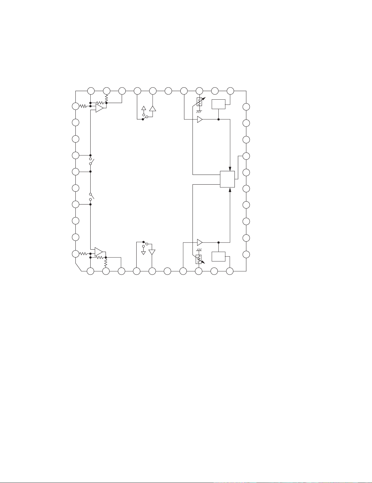
4.9 LA6541-X (IC801) : Servo driver
• Pin layout & Block diagram
Vcc Vref Vin4 Vg4 Vo8 Vo7
24 23
11k
ohm
22
21
20
19
Gnd
Vcc
Vo6 Vo5 Vg3 Vin3 Cd Res
18
17 16
15
14
13
11k
ohm
- +
- +
Level
shift
Level
shift
B T L
driver
B T L
driver
11k
ohm
1
Vcc Mute Vin1 Vg1 Vo1 Vo2 Vo3 Vo4 Vg2 Vin2 Reg
2
3456
Gnd
789101112
• Pin function
Pin No. Symbol Description
1 Vcc Power supply (Shorted to pin 24)
2 Mute All BTL amplifier outputs ON/OFF
3 Vin1 BTL AMP 1 input pin
4 Vg1 BTL AMP 1 input pin (For gain adjustment)
5 Vo1 BTL AMP 1 input pin (Non inverting side)
6 Vo2 BTL AMP 1 input pin (Inverting side)
7 Vo3 BTL AMP 2 input pin (Inverting side)
8 Vo4 BTL AMP 2 input pin (Non inverting side)
9 Vg2 BTL AMP 2 input pin (For gain adjustment)
10 Vin2 BTL AMP 2 input pin
11 Reg Out External transistor collector (PNP) conn ection. 5V power supply output
12 Reg In External transistor (PNP) base connection
13 Res
Reset output
14 Cd Reset output delay time setting (Capacitor connected externally)
15 Vin3 BTL AMP 3 input pin
16 Vg3 BTL AMP 3 input pin (For gain adjustment)
17 Vo5 BTL AMP 3 output pin (Non inverting side)
18 Vo6 BTL AMP 3 output pin (Inverting side)
19 Vo7 BTL AMP 4 output pin (Inverting side)
20 Vo8 BTL AMP 4 output pin (Non inverting side)
21 Vg4 BTL AMP 4 output pin (For gain adjustment)
22 Vin4 BTL AMP 4 output pin
23 Vref Level shift circuit's reference voltage application
24 Vcc Power supply (Shorted to pin 1)
B T L
driver
B T L
driver
Level
shift
Level
shift
11k
ohm
out
RESET
Regulator
Reg
In
1-32 (No.22044)
Page 33

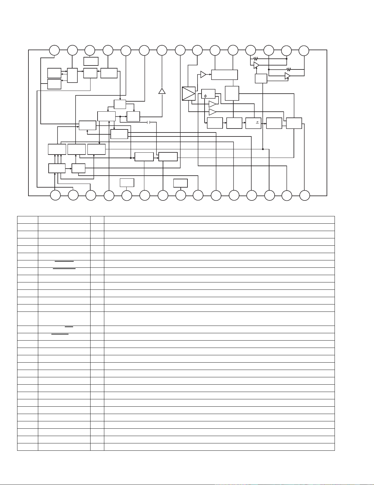
4.10 LC72136N (IC2) : PLL frequency synthesizer
•Pin layout
1
XT
FM/AM
CE
CLOCK
DO
FM/ST/VCO
AM/FM
SDIN
DI
2
3
4
5
6
7
8
9
10
11
22
21
20
19
18
17
16
15
14
13
12
XT
GND
LPFOUT
LPFIN
PD
VCC
FMIN
AMIN
IFCONT
IFIN
• Block diagram
UX-H33
1
22
16
15
3
4
5
6
17
21
1/2
C
2B
I/F
Power
on
Reset
Reference
Swallow Counter
Swallow Counter
Programmable
Data Shift Register & Latch
7821113
• Pin function
Pin
Symbol I/O Function
No.
1 XT I X'tal oscillator connect (75kHz)
2FM
/AM O LOW:FM mode
3 CE I When data output/input for 4pin (input)
and 6pin (output): H
4 DI I Input for receive the serial data from
controller
5 CLOCK I Sync signal input use
6 DO O Data output for Controller Output port
7 FM/ST/VCO O Low: MW mode
8AM
/FM O Open state after the power on reset
9 LW I/O Input/output port
10 MW I/O Input/output port
11 SDIN I/O Data input/output
12 IFIN I IF counter signal input
Driver
1/16,1/17 4bit
1/16,1/17 4bit
12bit
DriverS
Phase
Detector
Charge Pump
Unlock
Detector
Universal
Counter
Pin
Symbol I/O Function
No.
18
19
20
12
13 IFCONT O IF signal output
14 - Not use
15 AMIN I AM Local OSC signal output
16 FMIN I FM Local OSC signal input
17 VCC - Power suplly (VDD=4.5-5.5V)
When power ON:Reset circuit move
18 PD O PLL charge pump output (H: Local
OSC frequency Height than Reference
frequency. L: Low Agreement: Height
impedance)
19 LPFIN I Input for active lowpassfilter of PLL
20 LPFOUT O Output for active lowpassfilter of PLL
21 GND - Connected to GND
22 XT
I X'tal oscillator (75KHz)
(No.22044)1-33
Page 34

UX-H33
/
4.11 LC72723(IC3): RDS demodulation
• Pin layout
VREF
MPXIN
Vdda
Vssa
FLOUT
CIN
TES
XOUT
• Block Diagram
RDS-ID/READY
Vdda
Vssa
16
RDCL
15
RDDA
14
RST
13
MODE
12
Vddd
11
Vssd
10
XIN
9
REFERENCE
VOLTAGE
ANTI ALIASING
FILTER
TEST
VREF
57kHz
(SCF)
BPF
FLOUT
SMOOTHING
FILTER
CLK(4.332MHz)
OSC
VREF
CIN
+
PLL
(57kHz)
-
CLOCK
RECOVERY
(1187.5Hz)
DATA
DECODER
RAM
(128-bits)
RDS-ID
DETECT
Vddd
Vssd
RDDA
MODE
RST
RDS-ID
+5V
RDCL
READY
1
2
3
4
5
6
7
8
+5V
MPXIN
TEST
XIN
XOUT
• Pin functions
Pin No. Symbol I/O Function
1 VREF O Reference voltage output (Vdda/2)
2 MPXIN I Baseband (multiplexed) signal input
3 Vdda - A nalog power supply (+5V)
4 Vssa - Analog ground
5 FLOUT O Subcarrier input (filter output)
6 CIN I Subcarrier input (comparator input)
7 TEST I Test input
8 XOUT O Crystal oscilla tor output (4.332MHz)
9 XIN I Crystal oscillator input (exeternal reference input)
10 Vssd - Digtal ground
11 Vddd - Digtal power supply
12 MODE I Read mode setting (0:master, 1:slave)
13 RST I RDS-ID/RAM reset (positive polarity)
14 RDDA O RDS data output
15 RDCL I/O RDS clock output (master mode)/RDS clock input (slave mode)
16 RDS-ID/READY O RDS-ID/READY output (negative polarity)
1-34 (No.22044)
Page 35

4.12 LC75342 (IC302) : E. volume
• Terminal layout
30 16~
115~
• Block diagram
11
10
9 8 8 7 5
UX-H33
12
13
14
15
16
17
18
19
20
• Pin function
Pin No. Symbol Function
1 DI Serial data and clock input for IC control
2 CE Chip enable
3 VSS GND
4 TEST Electric volume connection for test
5 LOUT Volume control and equalizer input
6 LBASS2 Connection for resistor and capacitor that
from the bass band filter7 LBASS1
8 LTRE Connection for capacitor that from the treble
band filter
9 LIN Volume control and equalizer inp ut
10 LSEL0 Input selector output
11 L4 Not used
12 L3 Input signal connections, not used
13 L2 Input signal connections
14 L1 Input signal connections
15 NC GND
CONTROL
CIRCUIT
LOGIC
CIRCUIT
CONTROL
CIRCUIT
4
LVref
3
2
CCB
INTERFACE
1
30
RVref
29
28
27
262524232221
Pin No. Symbol Function
16 NC GND
17 R1 Input signal connections
18 R2 Input signal connections
19 R3 Input signal connections, not used
20 R4 Not used
21 RSEL0 Input selector output
22 RIN Volume control and equalizer input
23 RTRE Connection for capacitor that from the treble
band filter
24 RBASS1 Connection for resistor and capacitor that
from the bass band filter25 RBASS2
26 ROUT Volume control and equalizer input
27 NC Not used
28 VREF Connection to the 0.5X VDD voltage gener-
ator circuit used as the analog signal ground
29 VDD Power supply
30 CL Serial data and clock input for IC control
(No.22044)1-35
Page 36

UX-H33
4.13 MN662748RPMFA (IC603) : Digital servo & Digital signal processer
• Pin layout
80~61
1
60
20
41
21~40
• Pin function
Pin No. Symbol I/O Function
1BCLK-Not use
2 LRCK - Not use
3SRDATA-Not use
4 DVDDI - Power supply for digital circuit
5 DVSSI - GND for digital circuit
6TX-Not use
7 MCLK I Micro computer command clock signal
input
8 M DATA I Micro computer command data input
9 MLD I Micro computer command load signal in-
put (L: Load)
10 SENSE - Not use conn ect to TP716
11 FLOCK - Not use connect to TP717
12 TLOCK - Not use connect to TP718
13 BLKCK O Sub code block clock signal output
14 SQCK I External clo ck input for sub code Q reg-
ister input
15 SUBQ O Sub code Q data output
16 DMUTE - Not use connect to TP719
17 STAT O Status signal input
18 RST I Reset signal input (L: Reset)
19 SMCK - Not use
20 PMCK - Not use connect to TP720
21 TRV O Traverse enforced output
22 TVD O Traverse drive output
23 PC - Not used
24 ECM O Spindle motor drive signal (Enforced
mode output)
25 ECS O Spindle motor drive signal (Servo error
signal output)
26 KICK O Kick pulse output
27 TRD O Tra cking drive output
28 FOD O Focus drive output
29 VREF I Reference voltage for D/A output block
30 FBAL O Focus balance adjust signal output
31 TBAL O Tracking balance adjust signal output
32 FE I Focus error signal input (Analog input)
33 TE I Tracking error signal input (Analog input)
34 RFENV I RF envelope signal input (Analog input)
35 VDET I Vibration detect signal input (H:Detect)
36 OFT I Off track signal input (H:Off track)
37 TRCRS I Track cross signal input
38 /RFDET I RF detect signal input (L:Detect)
39 BDO I Drop out signal input (H:Drop out)
40 LDON O Laser on signal output
41 PLLF2 - Not use
42 TOFS - Not use
Pin No. Symbol I/O Function
43 WVEL - Not use
44 ARF I RF signal input
45 IREF I Reference current input
46 DRF I Bias pin for DSL
47 DSLF I/O Loop filter pin for DSL
48 PLLF I/O Loop filter pin for PLL
49 VCOF I/O Loop filter pin for VCO
50 AVDD2 - Power supply for analog circuit
51 AVSS2 - GND for analog circuit
52 EFM - Not use connect to TP724
53 PCK O Clock output for PLL
54 VCOF2 I/O Loop filter pin for Digital servo VCO
55 SUBC - Not use
56 SBCK - Not use
57 VSS - GND for crystal oscillation circuit
58 X1 I Input for crystal oscillation circuit
(f=16.9344MHz)
59 X2 O Output for crystal oscillation circuit
(f=16.9344MHz)
60 VDD - Power supply for crystal oscillation circuit
61 BYTCK/
TRVSTP
62 CLDCK O Sub code frame clock signal output
63 FCLK - Not used
64 IPFLAG O Interpolation flag signal output Connect
65 FLAG O Flag signal output Connect to TP722
66 CLVS - Not use
67 CRC - Not use
68 DEMPH O De-emphasis de tect signal output Con-
69 RESY - Not use
70 IOSEL I Mode select pin Connect to DVDD1 (H fix)
71 /TEST I Test pin Connect to DVDD1 (H fix)
72 AVDD1 - Power supply for analog circuit
73 OUTL O L-channel audio output
74 AVSS1 - GND for analog circuit
75 OUTR O R-channel audio output
76 RSEL I RF signal po larity setting pin Connect to
77 CSEL I Oscillation frequency setting pin Connect
78 PSEL I IO S E L = H Test pi n Connect to GND (L fix)
79 MSEL I IOSEL=H SMCK output Frequency se-
80 SSEL I IOSEL=H SMCK output SUBQ output
- Not use
to TP721
nect to TP723
DVDD1 (H fix)
to GND (L fix)
lect pin
mode select pin
1-36 (No.22044)
Page 37

4.14 MN101C57CEW (IC931) : System micon
•Pin layout
76 ~ 100
75 ~ 51
1 ~ 25
50 ~ 26
• Pin function
Pin No. Symbol I/O Description
1~3 VLC1~VLC3 - LCD BIAS VOLTAGE
4,5 - Not use
6 REEL I Tap e End Detection
7 _MPX I FM Stereo Detection ('L'=STEREO)
8 PERIOD O Tuner PLL Strobe
9 F_TU O Tuner Function ('H'=TUNER)
10 AHB O Active Hyper Bass('L'=ON)
11 VSS - GROUND
12,13 OSC1,OSC2 - MAIN OSC
14 MMOD - GROUND
15,16 X1,X0 - SUB OSC
17 VDD - 5V
18 _RST I/O Micon Reset
19 VDD O 5V
20 SDATA O Serial Data (Tuner PLL / Tape IC)
21 DIMCTL O LCD DIM control. DIMMER ON =L
22 SCK I Serial Clock (Tuner PLL / Tape IC)
23 STTA O Tape IC Strobe
24 QRIN O Q-code data input port
25 SQCK I Q-code serial clock
26 F_CD O CD Function ('H'=CD)
27 STAT I CD status input port
28 MUTE O BTL mute control port (MUTE ON = 'L')
29 RST/CLOSE O Door close detection
30 VOLCE I Volumn Chip Enable
31 BCTL I Switched 5V control('H'=5V'off)
32 BUP I Back up power detect('H'=BACKUP)
33 _REM I Remote control input
34 RDSCK I RDS clock
35 BLKCK - Block clock input port
36 FLAG - Error Correction Count
37,38 - Not use
39 VDD O 5V
40 VREF+ O 5V
41 _XRST O CD reset
42 MCLK O CD data clock
43 MDATA I CD data input port
44 MLD I CD command ready signal
45,46 KEY0,KEY1 I Unit Key input 0,1
47 DOOR_RST - REST/CLOSE switch detect port
48 CDSAFETY O CD safety voltage detect port
49 VREF- O GROUND
50 P_OUT O Power On/Off ('H'=Power On)
51,52 TAPE0,TAPE1 O Tape Switch 0Tape Switch 1
53~55 SAFETY2,0,1 O Irregular voltage detection 201
56 _SMUTE O System mute (MUTE on = 'L')
57~96 S39~S0 O SEGMENT OUTPUT
97~100 COM3~COM0 - LCD BIAS GROUND
UX-H33
(No.22044)1-37
Page 38

UX-H33
S
E
S
O
E
T
4.15 CD4094BC (IC33) : Serial to parallel port extension
• Pin layout
TROBE
CLOCK
• Block diagram
DATA
Q1
Q2
Q3
Q4
Vss
1
2
3
4
5
6
7
8
16
15
14
13
12
11
10
9
DATA
CLOCK
TROBE
Vdd
OUTPUT ENABL
Q5
Q6
Q7
Q8
Q's
Qs
2
3
1
8-STAGE
SHIFT REGISTER
8-BIT
LATHES
10
9
Q's
Qs
SERIAL
OUTPU
UTPUT
NABLE
15
Q1
3-STATE
OUTPUTS
Q8
PARALLEL OUTPUT
1-38 (No.22044)
Page 39

UX-H33
(No.22044)1-39
Page 40

UX-H33
VICTOR COMPANY OF JAPAN, LIMITED
AV & MULTIMEDIA COMPANY AUDIO/VIDEO SYSTEMS CATEGORY 10-1,1chome,Ohwatari-machi,Maebashi-city,371-8543,Japan
(No.22044)
Printed in Japan
200303WPC
Page 41

SCHEMATIC DIAGRAMS
MICRO COMPONENT SYSTEM
UX-H33
CD-ROM No.SML200303
UX-H33
Contents
Block diagram --------------------------------------------------------------------- 2-1
Standard schematic diagrams ------------------------------------------------ 2-2
Printed circuit boards ------------------------------------------------------ 2-8~10
MICRO COMPONENT SYSTEM
Area Suffix
B -------------------------- U.K.
E ------- Continental Europe
EN --------- Northern Europe
COPYRIGHT 2003 VICTOR COMPANY OF JAPAN, LTD.
No.22044SCH
Mar. 2003
Page 42

UX-H33
In regard with component parts appearing on the silk-screen pr inted side (par ts side) of
the PWB diagrams, the parts that are printed over with black such as the resistor ( ),
diode ( ) and ICP ( ) or identified by the " " mark nearby are critical for safety.
(This regulation does not correspond to J and C version.)
Page 43

Block diagram
UX-H33
5
IFOUT
IC2
PLL
CK,CE,DATA
MOTOR
SOLENOID
MUTE/IFOUT
FM/AM,SDIN
ST/MONO
AMOSC
HEAD
SWITCH
DRIVE
DRIVE
FM DET
AM DET
L1
OSCOUT
AMRF
AFC
AMOSC
FM/AM
ANT
J1
TU1
FM RF
AM RF
& OSC
CN31
4
RP MECHA
HEAD
L+,L–
R+,R–
FW100
M
MB
REEL
PULSE
CN42
CN32
SWITCH
FM OUT
RDS
IC1
LOUT
ROUT
IC32
PB/REC
IC33
PORT
MS,PBL,PBR
RECL,RECR
STTA,SDATA
SCK
AMP
EXTENSION
SOL,KEY1,PLAY,PHOTO
IC3
RDCL
RDDT
STEREO
CN1
CN34 CN33
DATA
CK
TUNER
SDATA/VOLDA
SCK/VOLCK
FTUNERSW
SWITCH
MPX
RDSCK
QRIN
TAPE1,TAPE0,SAFETY1
SCK,SDATA,STTA,REEL
LCD
COM0 to COM3
S0 to S39
IC931
MICOM
SAFETY2
SAFETY0
AHB
SMUTE
FTUNER
FCD
SDATA/VOLDA
SCK/VOLCK
VOLCE
POUT
REM
IC750
REMOCON
LCD LAMP
FW701
CD DOOR
CN717
FW701 CN716
SWITCH
RST/CLOSE
S7500 to S7512
KEY MATRIX
KEY0,KEY1
CN712CN713CN714
SOLENOID
3
A,B,C,D
CN601
E,F,LD,MD
CD
PICKUP
T+,T–
F+,F–
IC601
RF & SERVO
AMP
OFT,BDO
ARF,RFENV
TBAL,FBAL
FE,TE
GCTL,RFDET
VDET
REST
CN604 CN603
AUX IN
J301 CN301
L,R
SCK/VOLCLK
SDATA/VOLDI
VOLCE,TUL,TUR
TUL
TUR
IC302
E.VOL
IC602
2
REST
SWITCH
FEED
MOTOR
SPINDLE
FW602
FM+
FM–
SM+
SM–
TRD,FOD
ECM,ECS
TVD,TRV
KICK
DIGITAL SERVO/DSP
BTL DRIVER
XRST,STAT,SUBQ
SQCK,BLKCK,MLD
MDATA,MCLK
FLAG,SCD
IC603
BTLM
OUTL
OUTR
L,R
MOTOR
RECL,RECR
CN305CN303
PBL,PBR
CN711
FTUNER
TU+B
LAMP 8V
LOUT
ROUT
BASS BOOST
TUNER SW
IC301
AMP
5.6V
OUT1
OUT2
IC300
POWER AMP
SAFETY2
FCD
CD 8V
SW 8.8V
POUT
+L,+R
–L,–R
J300 J302
SPEAKER
HEADPHONE
CN901
W306
T901
TRANS
L901
J901
AC
INPUT
DIODE
BRIDGE
1
J902
ABC DEFGH
2-1
Page 44

UX-H33
UX-H33
Standard schematic diagrams
Primary section
5
!
F903
T6.3AL
!
0.1
D902
C902
6A10E2
C903
CN901
QGA2501C1-02
C901
D901
0.1
!
6A10E2
4
T901
QQT0396-002
!
D905
6A10E2
!
!
0.1
6A10E2
D903
F901
T500mAL
0.1
C904
!
D904
!
!
QQR1321-001
QNC0091-001
J902
QNA0016-001
6A10E2
L901
J901
!
!
F903
CN901
!
0.1
C901
QGA2501C1-02
6.3A/125V
!
6A10E2
R901
!
0.1
D901
C902
!
QRZ9037-335
T901
!
6A10E2
QQT0396-001
D902
C903
D905
!
0.1
6A10E2
F902
!
D903
1A/125V
!
0.1
C904
6.3A/125V
F901
QNC0092-001
6A10E2
6A10E2
F903
T6.3AL
!
J902
QNA0016-001
!
D904
!
J901
!
CN901
QGA2501C1-02
C901
!
6A10E2
0.1
D901
C902
!
6A10E2
0.1
!
T901
D902
QQT0396-002
C903
0.1
T500mAL
6A10E2
D905
!
6A10E2
F901
D903
!!
!
J902
QNA0016-001
!
C904
6A10E2
0.1
!
D904
L901
QQR1321-001
QNC0091-001
!
!
J901
3
D903
!
6A10E2
!
!
0.1
6A10E2
D904
C904
!
L901
F901
QQR1321-001
QNC0091-001
J902
QNA0016-001
!
!
J901
!
D903
6A10E2
QNA0016-001
!
0.1
6A10E2
C904
D904
!
J902
D905
!
0.1
6A10E2
F903
CN901
QGA2501C1-02
!
T6.3AL
!
0.1
C901
6A10E2
D901
!
0.1
D902
C902
6A10E2
C903
2
F902
!
!
T901
QQT0396-003
Parts are safety assurance parts.
When replacing those parts make
1
sure to use the specified one.
S901
QSW0740-001
T6.3AL
T1AL
F901
QNC0091-001
QQR1321-001
L901
!
!
J901
!
!
F903
CN901
QGA2501C1-02
C901
!
T6.3AL
D901
!
0.1
6A10E2
C902
!
T901
QQT0396-002
!
0.1
6A10E2
D902
0.1
C903
T500mAL
D905
!
6A10E2
D903
F901
0.1
C904
6A10E2
!
6A10E2
!
QNC0091-001
D904
QQR1321-001
L901
QNA0016-001
!
J901
!
J902
CN901
!
F903
0.1
C901
QGA2501C1-02
T6.3AL
!
!
6A10E2
D901
D905
6A10E2
0.1
C903
T500mAL
!
6A10E2
!
0.1
D902
C902
!
T901
QQT0396-004
ABC DEFGH
2-2
Page 45

UX-H33
Amp section
2SC2785/FE/-T
Q2400
5
3.9K
R2503
0.1
0.1
0.0027
10/25
2.2K
R3503
C3501
IC302
LC75342
4
J301
QNN0090-001
R1600
30K
C1600
R2600
C2600
30K
30K
220P
R1601R2601
30K
220P
SCK/VOLCLK
R3501
SDATA/VOLDI
2.2K
VOLCE
C2510
C2504
C2506
C2505
0.1
0.1
0.0027
C1505
C1504
C1506
3.9K
R1503
4.7/50
4.7/50
10/25
4.7/50
C2507
C2502
C2508
100
R3500
4.7/50
4.7/50
10/25
4.7/50
C1502
C1507
C1510
C1508
C3500
100/16
C3405
R3405
SMUTE
AHB
3
2.2K
R2802
2.2K
R1802
C2955
0.01
C3502
D3504
D3505
C1503
R1803
2
R1800
2.7K
R2803
9.1K
9.1K
2.7K
R2800
C2503
10/35
10/35
R2402
10K
C2303
0.33
R2304R2301
4.7K
R2306
R2307
4.7K
R1307
4.7K
D3403
10/16
51K
C2300
0.068
IC301
HA17558A
C1300
0.068
R1301
4.7K
R1306
C1303
D9502
0.33
1N4003S-T5
R1402
10K
2SC2785/FE/-T
R1304
Q1400
D3402
100
10K3.9K
R3300
C2301
47/16
C3300
C1301
0.068
3.9K
R1302
C1302
4.7K
10K
R1303
R3402
R3403
22/50
C3404
120K
15K
R2303
R2302
4.7K
C2302
R2300
10/35
0.068
10/35
15K
150K
150K
9.1K
R3302
R2305
6.8K
R1300
150K
R3303
R9205
R9206
SAFETY2
6.8K
R1305
3K
3K
R2151
10K
C3301
82K47K
R1151
22/16
Q9201
KTB772/Y/
0.01
C9202
D9201
C9201
47/16
MTZJ4.3B-T2
R9203
2SC3576-JVC-T
Q1150
Q9202
2SC2785/FE/-T
82
D3151
Q2150
2SC3576-JVC-T
R3151
4.7K
470
R3152
Q3151
KRC102M-T
47/10
C3152
10K
R9201
10K
R9202
C9203
10/35
!
IC300
LA4663
J300
L1100
L2100
L3200
QQL231K-470Y
QNS0072-001
QQL231K-470Y
L1200
L2200
QQL231K-470Y
!
C2103 C1103
J302
330P
330P
C2102
C2104
10/35
C1104
10/35
Q3150
KRA101M-T
1K
R3150
1K
R3154
R3153
1K
D3150
MTZJ5.1C-T2
C2954
Q3111
KRC111M-T
Q9301
KTA1267/YG/-T
100/10
C9303
FCD
C1102
22K
2.2
R2101
0.1
C2101
D3400
D3401
Q9002
Q9001
KTA1046/Y/
!
22K
22K
R1400
Q9005
KRA114M-T
22K
R2400
R2401
R1401
!
100/35
1/50
1/50
C3400
C3401
0.056
0.056
4.7K
C3402
C3403
R9001
!
2SA1175/FE/-T
R9008
R9007
R9006
0.01
C3101
C3100
C2957
QEZ0635-828
4.7K
R3400
R9002
R9003
1
1
1
R9004
Q9003
6.8K
13K
R9020
D9001
1K
KRC114M-T
Q9004
1.5K
R9005
2.4K
5.1K
R9021
D9020
MTZJ5.6C-T2
470
R1102
Q3110
C2953
470
470
2SC3576-JVC-T
R2102
C3102
100/16
C2958
QJK002-021202
!
4.7
R9100
2.2
R2100
0.1
C2100
R3401
68
R9019
2.2
C3106
FTUNER
R9012
4.7K
2.2
R1101
R1100
0.1
0.1
C1101
C1100
100/16
D3152
2SC2785/FE/-T
R9013
470
4.7K
R9014
100/16
C3103
10/25
C2956
C3151
10/25
R3107
680
D9302
D9303
47/25
C9001
R9016
R9303
D9002
R3100
D3153
Q9302
2SC2785/FE/-T
4.7/50
1K
C9302
MTZJ8.2C-T2
R9015
4.7K
2SC2785/FE/-T
4.7K
C3104
10K
C9006
10/25
R3106
47K
R9304
100
3.9K
R9301
33K
R9302
C9002
0.01
C9003
220P
Q9006
QQR0621-001Z
QQR0621-001Z
W306
C1105
C2105
K1200
150
R1200
R2200
150
K2200
Q9070
QQR0621-001Z
K3800
CN305
QGF1205F1-10
SLCAGND
PBL
PBR
SW8V
RECR
RECL
1
2SC3576-JVC-T
C2959
470
R9070
C9070
10/25
CDL
CDR
CD+B
CN303
QGF1205C1-07
CN301
QGB1214J1-20S
SAFETY2
SAFETY0
AHB
SMUTE
FTUNER
FCD
POUT
VOLCE
US15V
SCK/VOLCLK
SDATA/VOLDI
LAMP8V
TUR
TUL
K9100
QQR0621-001Z
Parts are safety assurance parts.
When replacing those parts make
sure to use the specified one.
TUNER SIGNAL
CD SIGNAL
TAPE SIGNAL
AUX IN SIGNAL
MAIN SIGNAL
ABC DEFGH
2-3
Page 46

UX-H33
UX-H33
Micon / LCD & Key control section
BL701
C7006
0.001
82K
QQR0621-001Z
R7071
R7072
R7074
C7007
0.01
100K
R7053
Q7005
2SC2412K/R/-X
QUM022-12Z3Z3
SLR-342VC3F
10K
R7051
47K
QLL0147-001
BL702
QLL0147-001
FW701
D7777
10K
10K
D7005
R7052
FW701
FLAG
CDSAFETY
DOOR_RST
MLD
MDATA
MCLK
XRST
STAT
SQCK
QRIN
BLKCK
MUTE
D7008
MTZJ5.1C-T2
33K
270
D7006
100/16
C7009
MTZJ8.2B-T2
R7039
R7050
Q7006
KRA102S-X
R7070
D7009
D7007
KIA78S06P-T
KEY0
RST/CLOSE
KEY1
1K
22K
IC932
C7008
0.1
CN716
QGF1205C1-04
SAFETY2
SAFETY0
AHB
SMUTE
FTUNER
FCD
VOLCE
SDATA/VOLDA
SCK/VOLCK
9V
TU+B
TUL
TUR
CN711
QGB1214K1-20S
CN712
QGF1205F1-14
GND
RST/CLOSE
KEY0
KEY1
CN717
QGF1205F1-04
TUNER SIGNAL
5
DI701
QLD0260-001
C7051
0.01
COM1
COM0
COM2
COM3S0S1
S4
S2
S5
S3
S10
S9
S6
S8
S7
S16
S11
S12
S13
S14
S15
S17
S20
S18
S19
4
S24
S22
S23
S21
S20
R7000
S19
S18
S17
S16
S15
S14
S13
S12
S11
S10
S9
S8
S7
S6
S5
S4
S3
S2
S1
S0
COM3
COM2
COM1
COM0
R7001
R7002
R7003
33K33K
33K
15K
C7000
C7002
0.1
C7001
0.1
C7018
0.01
0.1
18p
C7017
R7057
X7001
R7073
1M
TAPE1
C7022
Q7000
D7000
KRC111S-X
D7001
TAPE0
SAFETY1
Q7001
KRC111S-X
R7063
10K
R7062
STTA
2K
PERIOD
R7060
R7058 R7059
2SC2412K/R/-X
390K 82K
100K
SDATA/VOLDA
FTUNERSW
SCK/VOLCK
TU+B
LOUT
ROUT
RDSCK
QRIN
Q7002
C7021
0.01
MPX
9V
R7061
FTUNERSW
2.2K
REM
REEL
GP1UM281YK
IC750
C7019
0.001
C7020
47/16
R7064
10K
CN713
QGF1205F1-09
3
C7023
150p
150p
CN714
QGF1205F1-13
2
S25
R7004
S21
S26
REEL
2.2K
82K
18p
C7016
S24
S22
S23
S29
S27
S28
FTUNER
PERIOD
MPX
2.2K
2.2K
1k
R7005
R7006
R7007
QAX0711-002Z
S26
S25
S27
S30
S31
IC931
MN101C57CEW
AHB
2.2K
R7008
100/10
0.001
C7014
C7015
S29
S28
S32
S34
S33
10K
R7009
2SA1037AK/R/-X
0.01
C7013
S30
S35
D7002
S31
S36
0.01
C7003
2200/6.3
S32
S37
C7012
S33
R7010
Q7003
S34
S39
S38
1k
C7004
R7011
S37
S35
S36
SAFETY0
R7042
R7041
1K
2.2K
2.2K
R7043
SAFETY1
SDATA/VOLDA
SCK/VOLCK
1K
150
R7014
R7012
150p
47K
47K
R7013
QQL231K-470Y
R7056
330
R7044
2.2K
L7002
1
S38
S39
SAFETY2
2.2K
2.2K
R7045
DOOR_RST
RST/CLOSE
1K
R7016
R7015
QRIN
100p
C7005
R7055
2.2/50
C7011
STTA
2.2K
R7046
TAPE1
TAPE0
CDSAFETY
KEY1
KEY0
MDATA
MCLK
XRST
FLAG
BLKCK
RDSCK
REM
VOLCE
MUTE
STAT
FCD
SQCK
R7018
R7019
10K
R7017
10K
Q7004
C7050
R7047
R7048
R7049
R7038
MLD
R7029
R7028
R7027
R7026
R7025
R7020
1K
47K
QQL231K-4R7Y
L7003
L7001
QQL231K-100Y
KRC111S-X
0.01
56K
100K
10K
K7002
R7037
R7036
R7035
R7034
R7033
R7032
R7031
R7030
R7024
R7023
R7022
R7021
QQR0621-001Z
10K
R7054
KRC111S-X
Q7010
K7003
D7003
C7010
4.7/50
D7004
2.2K
R7065
18K
R7040
2.2K
2.2K
2.2K
1K
2.2K
2.2K
1K
2.2K
2.2K
10K
2.2K
2.2K
2.2K
1K
1K
2.2K
1K
1K
S7550
QSW0122-001
R7501 R7503 R7504R7502
R7500
1K1K1K
S7500
S7507
R7509
1.2K
S7501
S7508
C7501
0.01
R7508
R7507
1K
C7502
S7506
0.01
1.8K
1.2K
S7502
R7511
2.2K
1.8K
S7509
S7503
S7510
R7505
2.7K
2.2K
S7504
R7512R7510
R7513
2.7K
3.9K
S7511
S7505
S7512
R7506
C7500
0.01
R7514
C7503
0.01
ABC DEFGH
2-4
Page 47

UX-H33
ARF
R607 R609
C619
560P
RFENV
C610
0.039
R605
680k
33K 220K
C620
100P
BDO
OFT
C612
C611
0.01
0.0027
R606
180k
RFDET
C608
C628
C629
R608
R634
C625
0.0022
0.056/50
C613
D662
1SS133-T2
R621
NI
C624
220K
0.022
R635
C623
1/50
0.047/25
220/10
390k
330p
10
CD servo control section
E
F
0.082
0.022
0.022
5
CN601
QGF1008F1-16
VREF
R625
18K
E
R624
0
4
R617
R618
R623
R626
F+
T+
TF-
18K
D
0
A
0
B
0
C
F
C606
C615
Q602
0.022
NI
C602
56P
C603
NI
C616
AN22000A-W
IC601
R629
2.2k
12
R615
Q601
KTA1271/OY/-T
10
R614
C605
10/25
C617
R627
3.3p
C614
6.8k
1
R628
4.7k
D
B
C
A
C622
120
R613
3
C642
0.01/50
F-
T-
T+
2.2K
C635
C636
390p
2
FW602
QJK018-060601
DGDGDGDG
FMFM+
SMSM+
IC602
!
LA6541-X
R657
390p
0.015
C644
R650
R648
1.2K
R642
3.3K
C645
2.2/50
R641
56K
R649
1.5k
R647
C643
2.2/50
1k
C631
1
C641
470/10
3.9k
TRD
KICK
FOD
C604
100/10
C621
TBAL
FBAL
FE
TE
VDET
NI
R610
FBAL
TBAL
FE
TE
RFENV
VDET
OFT
RFDET
BDO
ARF
TP603
MLD
MDATA
2.7k
R697
0.33
C695
MCLK
C668
470/6.3
C677
0.022/25
C651
12p
C652
15p
R659
C669
QCZ0202-155Z
470
X651
QAX0413-001Z
C655
470/6.3
22
R666
C675
0.001
C674
0.022/25
C673
470/10
D661
0.0022/16
C672
1SS133-T2
QQR1183-001Z
K601
1k
R671
0.0022/16
C671
1k
R672
BTLM
BLKCK
SUBQ
SQCK
STAT
XRST
MCLK
MDATA
MLD
REST
FLAG
CN604
QGF1205F1-14
1k
R669
XRST
1k
1k
R651
C653
0.022/25
C694
100p
TRV
TVD
ECM
ECS
KICK
TRD
FOD
R612
1k
C618
1M
0.1/50
R619
68k
20k
R602
33k
R603
K602
QQR1183-001Z
IC604
C632
R668
470p
0.022/25
C662
R662
KIA78S05P-T
C661
100/10
C670
100/10
22
1.5M
C638
68k0.022
R661C663
0.1
C676
0.001
R652
120k
R663
C664
C691
150p
C692
1k
100
100
150p
C693
R654
R653
R656
150p
IC603
MN662748RPMFA
330
68k
R667
R664
0.33
0.022/25
C665
BLKCK
SQCK
SUBQ
STAT
C633
C634
390p
SM+
FM+
390p
FM- F+
R643
R644
R645
R646
47K
6.8K
33K
1.8K
TRV
TVD
ECM
ECS
CN610
QGA2501F1-02
R632
1
47k
SM-
CN603
QGF1205F1-07
Parts are safety assurance parts.
When replacing those parts make
sure to use the specified one.
CD SIGNAL
ABC DEFGH
2-5
Page 48

Cassette mechanism control section
UX-H33
UX-H33
IC1
5
D340
MTZJ5.1B-T
2.2K
R303
R302
2.2K
Q342
KRA111M-T
R306
4.7K
R344
4.7K
R345
4.7K
R346
C301
4.7K
100/10
R301
4
QAH0101-001
C220
QGF1205F1-06
CN31
C120
4.7P
4.7P
Q343
2SC3576-JVC-T
Q344
2SC3576-JVC-T
Q345
2SC3576-JVC-T
Q346
2SC3576-JVC-T
220
R207
9.1K
R107
9.1K
C209
R216
R116
C109
1K
4.7/25
1K
4.7/25
0.0068
0.0068
C110
C210
C101
820P
C201
820P
1/50V
47/50V
C104
220p
47/50V
C340
C341
C342
C204
220p
C102
0.01
C202
0.01
R102
R101
HA12237F
R201
R202
R104
5.1K
5.1K
0.1
0.1
C113
C106
2.2/50V
C103
IC32
C203
0.1
C213
C206
2.2/50V
0.1
5.1K
5.1K
R204
3
QVP0008-203Z
C121
R121
15K
330P
C221
R221
15K
330P
TP100
R327
470K
2
VR31
0.0047
C319
0.022
C316
L301
QQR1118-001
100/10
C313
2.2K
R106
11K
R206
11K
2.2K
L303
VQP0033-100Z
1.5
C314
R105
R205
100K
100K
C105
R313
C205
2SK2001
390P
390P
Q302
2.2
R310
4.7
2SK2001
Q372
KRC107M-T
FW100
Q371
R372
270P
C107
R108
RECL
27K
PRL
R110
10k
R336
22K
R339
100K
C304
10/16V
C306
220/10V
R210
10k
!
R353
10
R315
R314
15K
100
C308
0.0015
0.022
C310
!
R335
Q305
2.2K
1/50V
C207
270P
C300
R208
27K
R304
R305
!
100
10K
C307
RECR
PBR
0.001
KTC3199/GL/-T
Q375
Q376
R375
2SB562/C/
150
C376
R376
MSI-5U2LWA
0.01
D375
MTZJ5.1B-T
4.7K
R371
12K
QVP0077-103Z
KTA1271/OY/-T
1K
IC33
SW5
VR37
CD4094BC
KRC107M-T
QSW0832-001
SW1
Q347
QSW0832-001
QSW0832-001
SW2
R338
3.3K
R337
3.3K
C371
4.7/25
SW6
QSW0859-001
QGF1205F1-09
QGF1205F1-09
R340
680
R347
SG-105F3
CN42
CN32
10K
1SR139-400-T2
24K
R342
C374
100/10
22/16
C331
VKZ3174-00B
D1
12K
R341
18K
R343
CN34
QGF1201F3-10
1
Parts are safety assurance parts.
When replacing those parts make
sure to use the specified one.
CN33
QGF1205F1-09
TAPE SIGNAL
ABC DEFGH
2-6
Page 49

UX-H33
Tuner section
5
TU1
QAU0160-001
C1
0.022
C3
0.001
1SS133-T2
D3
D4
1SS133-T2
10/16
R5
33
CF1
QAX0420-001
C2
R3
R2
470K
2SC1623/5-6/-X
Q1
0.01
330
R4
330
0.01
0.01/16V
C5
C4
1.5K
0
R7
R6
C25
100/16
C15
12P
C16
12P
56
4
1SS133-T2
D1
1SS133-T2
J1
QNB0153-001
R1
D2
C8
C10
5P
L3
4.7
3
0.001
0.001
C9
C8
L1
QQR0796-003
C12
C13
0.047
10K
R13
R15
3.3K
C11
0.1
10P
R14
100K
C14
10/16
2
C81
0.001
100
R9
R16
4.7K
R17
1K
C7
0.001
X1
C28
QAX0402-001
C22
C23
C24
IC2
150P
150P
150P
10/16
0.0039
R23
1.8K
R10
2.2K
LC72136N
R50
C17
C18
0.47/50
C20
0.001
0.047
C19
R26
2.2K
R25
R22
4.7K
1K
1K
1K
1K
R18
R19
R20
330
R21
5.6K
Q5
DTA114YKA-X
R29
10K
R24
10K
R27
R28
10K
10K
C9
0.001
0.001
C54
C53
0.047
22/16
C77
680P
R41
3.3K
T1
QQR0793-001
C80
C6
0.001
R43
3.9K
C57
0.001
CF2
QAX0458-001Z
C51
1/50
LA1838
IC1
C48
0.0022
C58
0.047
C49
470P
C50
22/16
R40
C46
C33
0.047
C32
0.047
C31
22/16
C21
0.022
R33
0
R60
39k
0.022
47
R34C34
0.022
0.047
C35
5.6k
R35
CF3
QAX0610-001Z
270
NC
C60
C47
1/50
R38
C45
10/16
39K
C44
10/16
R39
39K
C43
0.027
C42
0.027
C40
C41
10/16
10/16
R37
10K
R36
3.3K
1/50
0.22/50
C38
C37
1/50
C39
C36
1/50
C73
C70
0.1
1K
1K
R72
R73
LC72723
IC3
C30
100/16
R32
1K
C59
0.001
R31
1K
10/16
C76
330P
C74
C75
L70
C72
0.1
560P
100
22P
X70
QAX0263-001Z
C71
22P
CN1
1
TUNER SIGNAL
ABC DEFGH
2-7
Page 50

Printed circuit boards
UX-H33
UX-H33
K602
C613
C622
R634
C606
C677
R619
R657
C621
R617
R610
C625
C624
R623
C645
R612
R668
R648
R625
R642
IC603
C618
R641
R647
IH602
C642
R669
C673
C653
R646
C635
R645
R632
C669
R649
R644
C633
C674
C655
C694
R652
R651
C634
R643
IC602
C641
C644
C675
C643
C693
C692
R650
R656
R654
R653
FW602
C631
R666
D661
C691
R696
R671
K601
R672
CN604
C636
R655
C638
C672
CN605
C676
C671
C632
IC604
CN603
S901
D9502
R3503
R3501
D9501
C9006
J902
J901
L901
CN301
R2803
R2802
R1803
R1802
C1510
R901
CN305
R659
C652
X651
C651
R661
C603
C619
C607
IH603
C602
C610
C623
Q602
R607
C662
C611
C620
R608
R609
R626
CN601
R618
C668
R602
R603
C612
IH601
C604
R635
R624
C696
C695
R697
C628
D662
C605
R621
Q601
CN610
C663
R614
R664
C608
CN611
R613
R615
C665
R662
C614
C629
R667
C617
C615
R616
C664
R627
IC601
R628
R663
R629
R605
C616
C670
C661
R606
5
4
3
CD board
Trans board
C9070
R9070
C2959
K3800
C1507
R1800
C2510
Q9070
C2507
Z901
R2800
C2508
C1503
C2506
R2503
Z911
C2505
C2504
IC302
T901
C3501
Z902
Z912
R1304
CN901
C3500
R3500
R1307
R9301
R2307
R1306
R9302
C2303
R2306
C9302
C9303
C901
C902
Z903
Z913
D901
D902
C904
D904
D903
D905
C903
R9304
PP901
Q9302
R9303
D9303
D9302
Q9301
C1508
C2503
C2502
C1502
2
Q3150
Main board
R1200
L3200
R1102
L1200
1
L2200
J302
R2102
K2200
R2200
C3102
R2600
R2601
C2600
R1600
R3153
R3151
D3150
Q3111
J301
R1601
C3151
R3107
C1600
L2100
D3151
R3152
D3152
D3153
R3154
R3150
Q3110
C2105
C2103
R3106
Q3151
C3152
C3106
J300
CN303
K9100
R9100
C3100
C2950
K1200
C2951
C1105
L1100
C1103
C1302
W306
C2957
C3101
R1302
R1303
C2956
R2305
C2958
R2303
R2151
C2102
C3103
IC300
C3301
R2302
C2104
IC301
Q2150
C1506
R3303
Q1150
R1503
R1300
C2302
C1104
R1151
C3402
R1305
C3104
C1505
R3100
C1102
C1504
R3403
R3401
C3105
D3401
R1301
R2300
D3400
R1400
C3300
R2400
C1301
C3400
R1401
R1100
R2100
R3302
R3300
C3404
C3401
R1101
R2101
R3301
R2401
Q1400
R1402
R3402
C3403
C1100
C1101
C2953
R9004
R9003
R9001
R9002
C2101
C2100
C1300
R2301
R9013
C9003
C2301
D3402
Q9004
Q9003
R3400
Q9001
C1303
C2954
D9001
Q9002
C2300
R9021
R9007
R9015
C9002
D9002
R2304
Q2400
R2402
D3403
C3405
R3405
R9006
Q9006
R9005
R9019
Q9005
R9012
R9014
Q9201
C9001
R9016
R9205
C9201
D9201
C9202
R9008
D9020
R9020
C2955
R9206
R9201
R9202
R9203
C9203
C3502
Q9202
D3504
D3505
ABC DEFGH
2-8
Page 51

PP701
UX-H33
Micon board
EP740
CN714
BL701
FW701
BL702
CN717
C7501
R7500
R7501
S7500
5
S7511
R7513
S7510
R7514
C7503
S7508 S7509
S7507
R7508
R7507
C7502
Switch board
D8
D7
L3
D4
D3
C13
R14
R9
D10
TP1
D9
R8
D2
D1
D6
D5
S7501
R7512
R7502
S7502
R7503
R7511
S7503
R7510
R7504
S7504
R7505
R7509
S7505
R7506
C7500
S7506
C8
J1
C7008
R7072
Q7002
B51
R13
R5
C7011
D7002
C7012
R7050
B63
B66
C1
R7071
R7056
Q7006
C3
TU1
D7007
IC932
C7009
C7010
D7008
CN713
B62
B65
Q3
CN711
S7512
S7550
C10
C12
Q4
R1
FW701
CN712
D7001
R7037
R7033
R7017
R7038
4
CN715
3
R7027
C7019
C7018
C7020
2
R72
R73
B61
R70
C73
C70
L70
X70
1
R7031
R7032
R7034
D7009
R7070
R7040
R7029
R7030
R7062
R7028
R7026
R7025
R7022
R7023
R7024
L7003
R7064
R7035
R7036
R7043
C74
C71 C72
IC750
C59
C76
C75
B59
D11
R35
L4
K7002
B71
B70
C35
C6
C25
C26
R32
R34
C34
CN1
R29
R17
C33
C23
C27
R7049
R7048
C7006
R7047
B50
C9
R31
C36
C39
R27
R28
R20
C22
C7
R23
C14
D7000
IC3
B69
C7024
C7022 C7023
R7063
Q7000
Q7001
R7053
C7007
R7074
C7005
R7018
R7021
R7020
R7019
R7014
R7015
R7016
R7046
R7045
C7050 C7051
R7044
R7042
R7041
C80
R39
R38
C45
C41
C42 C43
C40
R36
C38
R37
R33
R21
CF3
C16
C15
R10
C19
R22
C18
B68
C37
R19
R18
B58
C24
X1
R16
C17
C7004
B72
R24
R7013
DI701
C44
R60
C49
C30
R50
C47
R7011
C46
R26
R7012
IC931
C60
C21
IC2
R7010
R40
C7003
R7009
R7057
C31
T1
B60
C82
C32
R7003
R7001
C50
R41
D7005
C7015
C7014
C7016
C7017
C7002
C7000 C7001
R7002
C51
IC1
Q5
R7065
R30
C20
R25
C28
R7039
X7001
R7007
R7004
R7073
C7013
R7060
CF2
D7003
B67
R42
R7
B56
L7002
R7008
R7061
R7059
C77
L2
C5
R6
CF1
B80
B57
R7052
R7051
R43
C48
C57
L7001
C58
R2
C11
C55
K7003
B55
Q7005
R7055
C54
R4
B54
C53
R7006
C56
Q7003
R7005
C81
R3
D7006
D7004
Q7010
R7058
Q1
R7054
C7021
R7000
C2
B53
Q7004
CN716
D7777
L1
Q2
R11
R12
C4
B52
R15
Tuner board
A
BC
D
2-9
Page 52

UX-H33
5
SW1
4
Q305
R310
R313
C314
L301
C121
C313
R104
R304
D340
C107
C310
L303
R102
R335
R353
R339
R303
Q302
R315
R314
C308
3
R327
C316
C319
VR31
2
R121
C221
R221
R108
C113
R302
Q343
R301
C301
C103
Q342
C207
R208
C105
C205
C304
C106
Cassette (switch) board
SW2
R106
R101
C104
R306
Q344
D1
CN34
R105
C306
C102
R344
R205
R110
R345
Q345
C307
R336
C340
R206
C206
R346
VR37
R210
R305
C300
C341
R109
C110
R107
W1
Q346
P1
CN33
Q371
R372
Q372
C371
IC32
C101
R116
C109
CN31
R371
C374
Q375
R376
R216
C376
R204
R201
C202
C204
C201
W1
D375
R375
C213
C342
R207
Q376
C209
FW100
IC1
R338
R337
CN32
C203
R202
CN1
C210
R340
C331
R342
Q347
R347
SW6
R343
SW5
R341
IC33
1
2-10
A
Cassette board
BC
D
Page 53

UX-H33
< MEMO >
5
4
3
2
1
A
BC
D
2-11
Page 54

UX-H33
VICTOR COMPANY OF JAPAN, LIMITED
AV & MULTIMEDIA COMPANY AUDIO/VIDEO SYSYTEM CATEGORY 10-1,1chome,Ohwatari-machi,Maebashi-city,371-8543,Japan
(No.22044SCH)
Printed in Japan
200303
Page 55

PARTS LIST
[ UX-H33 ]
* All printed circuit boards and its assemblies are not available as service parts.
UX-H33
Area suffix
B ------------------------------- U.K.
E ----------- Continental Europe
EN ------------ Northern Europe
- Contents -
Exploded view of general assembly and parts list (Block No.M1)
Speaker assembly and parts list (Block No.M2)
Cassette mechanism assembly and parts list (Block No.MP)
Electrical parts list (Block No.01~04)
Packing materials and accessories parts list (Block No.M3,M5)
3- 3
3- 5
3- 6
3- 8
3-16
3-1
Page 56

UX-H33
< MEMO >
3-2
Page 57

UX-H33
Exploded view of general assembly and parts list
47
5
45
46
52
51
50
44
42
4
49
40
41
A
34
32
48
33
35
34
Block No.
h
35
38
M
M
1
M
71
Power ampliifier board
80
68
70
A
F
f
LCD system
D1
D
j
b
63
c
60
C
light board
65
6
7
57
57
61
D
79
61
61
62
79
E
58
76
75
74
76
77
73
78
73
72
37
81
3
43
f
91
CD servo
control baord
53
2
53
20
20
23
24
8
h
86
c
d
1
2
53
39
38
85
18
38
9
g
i
5
19
10
11
15
36
38
3
69
g
4
5
4
17
16
19
F
LCD system
CPU board
55
54
88
69
30
90
66
26
25
67
84
57
83
B1
j
82
Power
supply
board
57
B
e
69
59
Tuner
board
C
E
64
69
87
e
d
26
i
b
89
30
31
27
56
B
1
79
22
21
79
12
14
13
29
28
ABCD E F G
Head amplifier
& mechanism
31
control board
D1
B1
3-3
Page 58

UX-H33
UX-H33
Parts list (General assembly)
Item
A
1 GV10127-003A
2 GV40077-002A
3 GV20202-001A
4 QYSBSF2608Z
5 QYSBSF2608Z
6 GV30423-001A
7 GV40384-001A LCD FILTER 1
8 GV30402-002A
9 GV30349-009A
10 GV30424-001A
11 GV40393-001A EJECT LEVER 1
12 GV40377-001A
13 QYSBSF2608Z
14 VKZ4323-202
15 GV30421-001A TENSION SPRING 1
16 GV40394-001A
17 VKZ4341-205
18 GV40385-001A
19 QYSBSF3010Z SCREW 2 F.PNL/D.HOLDER
20 VKY4180-401
21 VYH5601-001
22 GV40386-001A
23 GV20198-001A CASSETTE HOLDER 1
24 GV30403-003A
25 GV30071-001A
26 QYSBSF2608Z
27 ------------------28 VKL7850-002
29 VKW5258-003
30 QYSBSF3012Z
31 QYSBST3008Z
32 KSM-213CCMJ
33 GV30412-001A
34 LV42763-001A
35 LV42763-002A
36 GV40379-001A
37 GV40379-002A
38 QYSBSF3010Z SCREW 4 CD CASE/M.HOLDE
39 GV40390-001A
40 GV10134-001A
41 VYH4769-002SS
42 GV40391-001A CD DOOR SPRING 1
43 GV40395-001A
44 GV40396-001A
45 GV20199-001A
46 QYSDSF2006M SCREW 1 CLAMP.BKT/CD DO
47 GV40378-001A
48 GV40423-001A
Parts number Parts name Area
FRONT PANEL
JVC BADGE
PUSH BUTTON
T.SCREW
T.SCREW
LAMP CASE
LCD LENS
SPACER
DOOR HOLDER
EJECT KNOB
T.SCREW
SCREW
EJECT ARM
SPECIAL SCREW
TORSION SPRING
CASSETTE SPRING
GEAR
DOOR SPRING
DOOR LENS
HEAD SHIELD
T.SCREW
SINGLE C,MECHA
EJECT SAFTY(R)
TORSION SPRING
SCREW
T.SCREW
CD MECHA ASSY.
PICK COVER
INSULATOR
INSULATOR
CDMECHAHOLDER
CDMECHAHOLDER
SHIELD
CD CASE
GEAR
LOCK LEVER
CD EJECT KNOB
CD DOOR
CD LENS
CLAMPER BKT
Q'ty
1
1
1
2
PUSH BUT./PWB
2
F.PANEL/PWB
1
1
1
STICK TO LED
1
1
1
E.LEVER/E.KNOB
2
D.HOLDER/E.LEVE
1
1
FOR EJECT ARM
1
2
1
1
1
CASS. DOOR/F.PA
1
2
1
1
1
2
F.PANEL/MECHA
2
D.HOLDER/MECHA
1
1
2
2
1
1
1
1
1
1
1
1
1
1
Description
Block No. M1MM
Parts list (General assembly)
Item
A
49 LV33270-001A
50 VYH7313-005
51 VKL7757-001
52 LV41741-001A
53 QYSBSF3010Z
54 GV40392-001A
55 E3400-431 SPACER 1 MICON PWB+SHIEL
56 GV10133-001A
57 QYSBST4006Z
58 GV30404-001A
59 QYSBSF2608Z T.SCREW 1 PWB/JACK HOLDER
60 GV30405-001A
61 QYSBST3012Z
62 QYSBST3006Z
63 QYSBST3006Z T.SCREW 1 MAIN PWB/CHASSI
64 QYSBST3006Z
65 GV30408-001A
66 GV30422-001A
67 QYSBST4006Z T.SCREW 1 SHIELD+BTM.CHAS
68 QYSBSG3006Z
69 LV30225-011A
70 GV10128-003A
71 GV20221-001A SIDE PANEL (L) 1
72 GV20218-001A
73 QYSBSF3010Z
74 QYSBSF3010Z
75 QYSBSF3010Z
76 QYSBSF3010Z
77 QYSBSF3010Z
78 QYSBSF3010Z
79 QYSSST3008Z
80 GV30406-007A
81 LV41843-001A
82 QQT0396-002
83 QMF51W2-R50-J8
84 QMF51W2-6R3-J8
85 QUQH12-0411BJ
86 QUQH12-0714AJ FLAT WIRE 1 FC303
87 QUQH12-1309BJ
88 QUQH12-0913BJ
89 QUQH12-1022BJ
90 QUQH12-1406BJ FLAT WIRE 1 FC712
91 QUQ110-1607AJ
Parts number Parts name Area
CLAMPER
MAGNET
YOKE
SPECIAL SCREW
SCREW
SHIELD
BOTTOM CHASSIS
T.SCREW
JACK HOLDER
RADIATION
T.SCREW
T.SCREW
T.SCREW
IC HOLDER
SHIELD
T.SCREW
SPACER
REAR PANEL
SIDE PANEL (R)
SCREW
SCREW
SCREW
SCREW
SCREW
SCREW
SCREW
NAME PLATE
LASER CAUTION
POWER TRANSF
FUSE
FUSE
FLAT WIRE
FLAT WIRE
FLAT WIRE
FLAT WIRE
FLAT WIRE
Q'ty
1
1
1
1
TO CLAMPER
4
CD PWB/CD CASE
1
MICON PWB
1
4
CHASSIS/TRANS
1
1
3
RADIATION/IC
1
RADIA/CHASSIS
1
TNR.PWB/CHASSIS
1
1
COVER POWER TRA
1
ERT.PLT/MAIN PC
4
1
1
2
R.PANEL/TUNER
1
R.PANEL/SPK.JAC
1
R.PANEL/AUX
2
R.PANEL/CD CASE
1
R.PANEL/AC IN
1
R.PANEL/DC IN
4
R.PANEL/CHASSIS
1
1
1
T 901
1
F 901
1
F 903
1
FC716
1
FC714
1
FC713
1
FC305
1
FC601
Block No. M1MM
Description
3-4
Page 59

Speaker assembly and parts list
(SP-UXH33)
5
6
6
Block No.
7
M
UX-H33
M
2
M
3
3
1
Parts list (Speaker)
A
Item
1 J201XH3000B10
2 J200XH3000B00
3 J282XH3000B00
4 21302UXP510
5 305J0XH300800
6 411B84012AB1
7 6000XH33E00 RATING LABEL 2
Parts number Parts name Area
4
3
3
2
Block No. M2MM
Description
SPEAKER FRAME
FRONT PANEL
LATCH
JVC MARK
WOOFER
SCREW
Q'ty
2
2
8
2
2
8
3-5
Page 60

UX-H33
Cassette mechanism assembly and parts list
Grease
= EM-30L
=UD-24
=LEN-320M
=MOBIL-1
34
SLC-S302M
8
3
13
27
Block No.
15
2
14
9
16
11
12
23
2
3
10
4
7
M
MM
P
6
5
1
29
C
1
The lower side
5
6
26
24
31
Switch board
30
25
22
17
C
36
11
18
21
28
A
B
19
20
A
33
33
3-6
32
0.1
_
+
8.7
0.15 mm
32
B
35
Head amplifier
board
35
Page 61

UX-H33
Parts list (Cassette mechanism)
Item
A
1 VKS1165-00L
2 VKS2274-002
3 VKW5286-002
4 VKS5559-001
5 VKS5595-002
6 VKS5560-003
7 LV42013-001A EARTH SPRING 1
8 SLC-PP3SVM
9 VKY3149-002
10 LV31786-001A
11 VKS1166-004 CONTROL CAM 1
12 VKW5279-002
13 VKW5280-001
14 LV41584-001A
15 LV41585-003A BRAKE(L) 1
16 QYSBSF2005Z
17 VKS5603-00G
18 VKS3785-001MM
19 VKW5284-002 SWING SPRING 1
20 VKS2278-003
21 VKW5301-001
22 VKW5266-001
23 WDL214025 WASHER 1
24 QYSBSF2005Z
25 VKS3786-00G
26 VKF3205-00B
27 WDL183425
28 VKF3207-00C
29 WDL173525-6
30 VKZ3174-00B
31 LV42836-001A
32 MSI-5U2LWA
33 VKR4761-003
34 QYSPSP2604Z
35 QYSBSF2608Z
36 QUQH12-0906BF
Parts number Parts name Area
CHASSIS B. ASSY
REEL GEAR
B.T. SPRING
PLAY IDLE GEAR
BLIND
FR IDLE GEAR
HEAD MOUNT ASSY
CASSETTE SP.
PLAY SW LEVER
HEAD BASE SP(R)
HEAD BASE SP(L)
BRAKE(R)
T.SCREW
MAIN PULLEY ASY
FR ARM
TRIGGER ARM
FR SPRING
ELEVATOR SPRING
T.SCREW
CLUTCH ASS'Y
F.WHEEL ASSY(R)
SLIT WASHER
F.WHEEL ASSY(L)
SLIT WASHER
DC SOLENOID
CAPSTAN BELT
D.C.MOTOR ASS'Y
MOTOR PULLEY
SCREW
T.SCREW
WIER
Q'ty
1
2
2
1
1
1
1
1
1
1
1
1
1
1
1
1
1
1
1
1
1
1
1
1
1
1
1
1
2
3
FOR P.W.B.
1
FC32
Block No. MPMM
Description
3-7
Page 62

UX-H33
)
)
)
)
)
)
)
)
)
)
)
)
)
)
)
)
)
)
)
)
)
)
)
)
)
)
)
)
)
)
)
)
)
)
)
Electrical p arts list (Main board)
Item
A
C 602 QCSB1HJ-560Y C CAPACITOR
C 604 QEKC1AM-107Z E CAPACITOR
C 605 QETN1EM-106Z E CAPACITOR
C 606 QFVF1HJ-823Z MF CAPACITOR
C 608 QETN1HM-105Z E CAPACITOR
C 610 QFVF1HJ-393Z MF CAPACITOR
C 611 QCBB1HK-103Y C CAPACITOR
C 612 QDXB1CM-272Y C CAPACITOR
C 613 QCBB1HK-331Y C CAPACITOR
C 614 QCZ0313-105Z C CAPACITOR
C 615 QDVB1EZ-223Y C CAPACITOR
C 616 QDVB1EZ-223Y C CAPACITOR
C 617 QCSB1HK-3R3Y C CAPACITOR
C 618 QFVF1HJ-104Z MF CAPACITOR
C 619 QCBB1HK-561Y C CAPACITOR
C 620 QCBB1HK-101Y C CAPACITOR
C 622 QFLC1HJ-223Z M CAPACITOR
C 623 QFVF1HJ-563Z MF CAPACITOR
C 624 QFLC1HJ-223Z M CAPACITOR
C 625 QDXB1CM-222Y C CAPACITOR
C 628 QDX31EM-473Z C CAPACITOR
C 629 QETN1AM-227Z E CAPACITOR
C 631 QETN1AM-477Z E CAPACITOR
C 632 QEKC1AM-107Z E CAPACITOR
C 633 QCBB1HK-391Y C CAPACITOR
C 634 QCBB1HK-391Y C CAPACITOR
C 635 QCBB1HK-391Y C CAPACITOR
C 636 QCBB1HK-391Y C CAPACITOR
C 638 QFVF1HJ-104Z MF CAPACITOR
C 641 QCZ0313-105Z C CAPACITOR
C 642 QCBB1HK-103Y C CAPACITOR
C 643 QEQ61HM-225Z NP E CAPACITOR
C 644 QFN31HJ-153Z M CAPACITOR
C 645 QEQ61HM-225Z NP E CAPACITOR
C 651 QCSB1HJ-120Y C CAPACITOR
C 652 QCSB1HJ-150Y C CAPACITOR
C 653 QDVB1EZ-223Y C CAPACITOR
C 655 QCZ0202-155Z ML C CAPACITOR
C 661 QCBB1HK-471Y C CAPACITOR
C 662 QDVB1EZ-223Y C CAPACITOR
C 663 QFLC1HJ-223Z M CAPACITOR
C 664 QDVB1EZ-223Y C CAPACITOR
C 665 QFVF1HJ-334Z MF CAPACITOR
C 668 QETN0JM-477Z E CAPACITOR
C 669 QETN0JM-477Z E CAPACITOR
C 670 QETN1AM-107Z E CAPACITOR
C 671 QDXB1CM-222Y C CAPACITOR
C 672 QDXB1CM-222Y C CAPACITOR
C 673 QETN1AM-477Z E CAPACITOR
C 674 QDVB1EZ-223Y C CAPACITOR
C 675 QDGB1HK-102Y C CAPACITOR
C 676 QDGB1HK-102Y C CAPACITOR
C 677 QDVB1EZ-223Y C CAPACITOR
C 691 QCBB1HK-151Y C CAPACITOR
C 692 QCBB1HK-151Y C CAPACITOR
C 693 QCBB1HK-151Y C CAPACITOR
C 694 QCBB1HK-101Y C CAPACITOR
C 695 QFVF1HJ-334Z MF CAPACITOR
C 901 QFLA1HJ-104Z TF CAPACITOR
C 902 QFLA1HJ-104Z TF CAPACITOR
C 903 QFLA1HJ-104Z TF CAPACITOR
C 904 QFLA1HJ-104Z TF CAPACITOR
CN301 QGB1214J1-20S CONNECTOR
CN303 QGF1205C1-07 CONNECTOR
CN305 QGF1205F1-10 CONNECTOR
CN601 QGF1008F1-16 CONNECTOR
Parts number Parts name Area
Block No. 01
Remarks
VREF
VREF(IC601
LD(IC601
PDF(IC601
CAGC(IC601
CEA(IC601
CBDO(IC601
COFTR(IC601
OFTR(IC601
RFIN(IC601
TBAL(IC601
FBAL(IC601
RFOUT(IC601
TE
FEOUT(IC601
TEOUT(IC601
VREF-VCC
RFENV
TEBPF
TEBPF(IC601
VCC(IC601
VCC(IC601
VCC(IC602
OUT(5V REG
SM+/FM+/T+/F+/IN(5V REG
VCC(IC602
TRD
FOD
FOD
TRD
X1(IC603
X1(IC603
RST(IC603
DVDD1(IC603
ARF
AVDD2(IC603
DSLF(IC603
IREF(IC603
PLLF(IC603
VDD(IC603
DVDD1(IC603
AVDD2(IC603
OUTR
OUTL
AVDD1(IC603
AVDD1(IC603
AG-DG
AG-DG
AG-DG
DENGEN N-MCLK
DENGEN N-MDATA
DENGEN NOISE-ML
DENGEN N-SQCK
VCOF2(IC603
RECTIFIER
RECTIFIER
RECTIFIER
RECTIFIER
TO MICON
TO CD
TO SLC
TO RF
Item
A
CN603 QGF1205F1-07 CONNECTOR
CN604 QGF1205F1-14 CONNECTOR
CN610 QGA2501C1-02 2P CONNECTOR
CN901 QGA2501C1-02 2P CONNECTOR
C1100 QFLC1HJ-104Z M CAPACITOR
C1101 QFLC1HJ-104Z M CAPACITOR
C1102 QCBB1HK-331Y C CAPACITOR
C1103 QDXB1CM-332Y C CAPACITOR
C1104 QTE1V06-106Z E CAPACITOR
C1105 QCBB1HK-221Y C CAPACITOR
C1300 QFLC1HJ-683Z M CAPACITOR
C1301 QFLC1HJ-683Z M CAPACITOR
C1302 QTE1V06-106Z E CAPACITOR
C1303 QFVJ1HJ-334Z MF CAPACITOR
C1502 QETN1HM-475Z E CAPACITOR
C1503 QTE1V06-106Z E CAPACITOR
C1504 QFVF1HJ-104Z MF CAPACITOR
C1505 QFVF1HJ-104Z MF CAPACITOR
C1506 QFLC1HJ-272Z M CAPACITOR
C1507 QETN1HM-475Z E CAPACITOR
C1508 QETN1HM-475Z E CAPACITOR
C1510 QETN1EM-106Z E CAPACITOR
C1600 QCBB1HK-221Y C CAPACITOR
C2100 QFLC1HJ-104Z M CAPACITOR
C2101 QFLA1HJ-104Z TF CAPACITOR
C2102 QCBB1HK-331Y C CAPACITOR
C2103 QDXB1CM-332Y C CAPACITOR
C2104 QTE1V06-106Z E CAPACITOR
C2105 QCBB1HK-221Y C CAPACITOR
C2300 QFLC1HJ-683Z M CAPACITOR
C2301 QFLC1HJ-683Z M CAPACITOR
C2302 QTE1V06-106Z E CAPACITOR
C2303 QFVJ1HJ-334Z MF CAPACITOR
C2502 QETN1HM-475Z E CAPACITOR
C2503 QTE1V06-106Z E CAPACITOR
C2504 QFVF1HJ-104Z MF CAPACITOR
C2505 QFVF1HJ-104Z MF CAPACITOR
C2506 QFLC1HJ-272Z M CAPACITOR
C2507 QETN1HM-475Z E CAPACITOR
C2508 QETN1HM-475Z E CAPACITOR
C2510 QETN1EM-106Z E CAPACITOR
C2600 QCBB1HK-221Y C CAPACITOR
C2953 QDGB1HK-102Y C CAPACITOR
C2954 QDGB1HK-102Y C CAPACITOR
C2955 QDGB1HK-102Y C CAPACITOR
C2956 QCBB1HK-103Y C CAPACITOR
C2957 QCBB1HK-103Y C CAPACITOR
C2958 QCBB1HK-103Y C CAPACITOR
C2959 QDGB1HK-102Y C CAPACITOR
C3100 QEZ0635-828 E CAPACITOR
A
C3101 QTE1V28-107Z E CAPACITOR
C3102 QEKC1CM-107Z E CAPACITOR
C3103 QETN1EM-476Z E CAPACITOR
C3104 QETN1EM-106Z E CAPACITOR
C3106 QETN1CM-107Z E CAPACITOR
C3151 QETN1EM-106Z E CAPACITOR
C3152 QETN1AM-476Z E CAPACITOR
C3300 QETN1CM-476Z E CAPACITOR
C3301 QTE1C06-226Z E CAP. SILMIC
C3400 QETN1HM-105Z E CAPACITOR
C3401 QETN1HM-105Z E CAPACITOR
C3402 QFLC1HJ-563Z M CAPACITOR
C3403 QFLC1HJ-563Z M CAPACITOR
C3404 QETN1HM-226Z E CAPACITOR
C3405 QETN1CM-106Z E CAPACITOR
C3500 QETN1CM-107Z E CAPACITOR
Parts number Parts name Area
Remarks
TO AUDIO
TO MICON
VL/GND
2CHA +OUT
2CHA -OUT
IN2
EMC EXP J/C
IN2
EMC EXP J/C
.068MF 5% 50V
.068MF 5% 50V
.33MF 5% 50V
AUXL
CDL
.10MF 5% 50V
.10MF 5% 50V
2700PF 5% 50V
PBL
TUL
RECL
220PF 10% 50V
1CHA +OUT
1CHA -OUT
IN1
EMC EXP J/C
IN1
EMC EXP J/C
.068MF 5% 50V
.068MF 5% 50V
.33MF 5% 50V
AUXR
CDR
.10MF 5% 50V
.10MF 5% 50V
2700PF 5% 50V
PBR
TUR
RECR
220PF 10% 50V
.010MF 10% 50V
.010MF 10% 50V
.010MF 10% 50V
8200MF
100MF 20% 16V
RF
RF
100MF 20% 16V
10MF 20% 25V
47MF 20% 10V
47MF 20% 16V
1.0MF 20% 50V
1.0MF 20% 50V
.056MF 5% 50V
.056MF 5% 50V
22MF 20% 50V
10MF 20% 16V
100MF 20% 16V
3-8
Page 63

UX-H33
)
)
)
Q
Q
Q
Q
Q
Q
Q
Q
Q
Q
Q
Q
Q
Q
Q
Q
Q
Q
Q
Q
)
)
)
)
Q
)
)
)
)
Electrical p arts list (Main board)
Item
A
C3501 QETN1EM-106Z E CAPACITOR
C3502 QDYB1CM-103Y C CAPACITOR
C9001 QETN1EM-476Z E CAPACITOR
C9002 QDYB1CM-103Y C CAPACITOR
C9003 QCBB1HK-221Y C CAPACITOR
C9006 QETN1EM-106Z E CAPACITOR
C9070 QETN1EM-106Z E CAPACITOR
C9201 QETN1CM-476Z E CAPACITOR
C9202 QDYB1CM-103Y C CAPACITOR
C9203 QTE1V06-106Z E CAPACITOR
C9302 QEKC1HM-475Z E CAPACITOR
C9303 QEKC1AM-107Z E CAPACITOR
D 661 1SS133-T2 SI DIODE
D 662 1SS133-T2 SI DIODE
D 901 6A10E2 SI DIODE
A
D 902 6A10E2 SI DIODE
A
D 903 6A10E2 SI DIODE
A
D 904 6A10E2 SI DIODE
A
D 905 6A10E2 SI DIODE
A
D3150 MTZJ5.1C-T2 ZENER DIODE
D3151 1SS133-T2 SI DIODE
D3152 1SS133-T2 SI DIODE
D3153 1SS133-T2 SI DIODE
D3400 1SS133-T2 SI DIODE
D3401 1SS133-T2 SI DIODE
D3402 1SS133-T2 SI DIODE
D3403 1SS133-T2 SI DIODE
D3504 1SS133-T2 SI DIODE
D3505 1SS133-T2 SI DIODE
D9001 1SS133-T2 SI DIODE
D9002 MTZJ8.2C-T2 ZENER DIODE
D9020 MTZJ5.6C-T2 ZENER DIODE
D9201 MTZJ4.3B-T2 ZENER DIODE
D9302 1SS133-T2 SI DIODE
D9303 1SS133-T2 SI DIODE
D9501 1SS133-T2 SI DIODE
D9502 1N4003S-T5 SI DIODE
FW602 QJK018-060601 SIN CR C-B WIRE
IC300 LA4663 IC
A
IC301 HA17558A IC
IC302 LC75342 IC
IC601 AN22000A-W I.C
IC602 LA6541-X IC
A
IC603 MN662748RPMFA IC
IC604 KIA78S05P-T IC
IH601 VYH7237-004 IC HOLDER
IH602 VYH7237-001MM IC HOLDER
IH603 VYH7237-003 IC HOLDER
J 300 QNB0117-001 SPK TERMINAL
J 301 QNN0090-001 PIN JACK
J 302 QNS0072-001 HEADPHONE JACK
J 901 QNC0091-001 AC INLET
A
J 902 QNA0016-001 DC JACK
A
K 601 QQR0621-001Z FERRITE BEADS
K 602 QQR0621-001Z FERRITE BEADS
K1200 QQR0621-001Z FERRITE BEADS
K2200 QQR0621-001Z FERRITE BEADS
K3800 QQR0621-001Z FERRITE BEADS
K9100 QQR0621-001Z FERRITE BEADS
L 901 QQR1321-001 LINE FILTER
A
L1100 QQR0797-002 INDUCTOR
L1200 QQL231K-470Y INDUCTOR
L2100 QQR0797-002 INDUCTOR
L2200 QQL231K-470Y INDUCTOR
L3200 QQL231K-470Y INDUCTOR
PP901 QZW0038-001 WIRE CLAMP
Parts number Parts name Area
Block No. 01
Remarks
10MF 20% 25V
GND TO CHASSIS
47MF 20% 25V
220PF 10% 50V
10MF 20% 25V
10MF 20% 25V
47MF 20% 16V
4.7MF 20% 50V
100MF 20% 10V
AVDD1
VCC(IC602
RECTIFIER
RECTIFIER
RECTIFIER
RECTIFIER
DC BLOCK
GND TO CHASSIS
GND TO CHASSIS
SAFETY0
BYPASS LAMP8V
CD MECHA-CD AMP
RF AMP
DRIVER
1CHIP PROCESSER
5V REG
FOR IC601
FOR IC602
FOR IC603
SPEAKER
AUX IN
AC IN
DC IN
AVSS1(IC603
VSS(IC603
EMC EXP J/C
EMC EXP J/C
SLCAGND
US15V
EMC FILTER
EMC EXP J/C
EMC EXP J/C
EMC EXP J/C
EMC EXP J/C
EMC EXP J/C
Item
A
A
R 602 QRE141J-203Y C RESISTOR
R 603 QRE141J-333Y C RESISTOR
R 605 QRE141J-684Y C RESISTOR
R 606 QRE141J-184Y C RESISTOR
R 607 QRE141J-333Y C RESISTOR
R 609 QRE141J-224Y C RESISTOR
R 610 QRE141J-105Y C RESISTOR
R 612 QRE141J-102Y C RESISTOR
R 613 QRE141J-121Y C RESISTOR
R 614 QRE141J-100Y C RESISTOR
R 615 QRE141J-120Y C RESISTOR
R 619 QRE141J-683Y C RESISTOR
R 621 QRE141J-100Y C RESISTOR
R 625 QRE141J-183Y C RESISTOR
R 626 QRE141J-183Y C RESISTOR
R 627 QRE141J-682Y C RESISTOR
R 628 QRE141J-472Y C RESISTOR
R 629 QRE141J-222Y C RESISTOR
R 632 QRE141J-473Y C RESISTOR
R 634 QRE141J-224Y C RESISTOR
R 635 QRE141J-394Y C RESISTOR
R 641 QRE141J-563Y C RESISTOR
R 642 QRE141J-332Y C RESISTOR
R 643 QRE141J-473Y C RESISTOR
R 644 QRE141J-682Y C RESISTOR
R 645 QRE141J-333Y C RESISTOR
R 646 QRE141J-182Y C RESISTOR
R 647 QRE141J-392Y C RESISTOR
R 648 QRE141J-122Y C RESISTOR
R 649 QRE141J-152Y C RESISTOR
R 650 QRE141J-182Y C RESISTOR
R 651 QRE141J-102Y C RESISTOR
R 652 QRE141J-102Y C RESISTOR
R 653 QRE141J-101Y C RESISTOR
R 654 QRE141J-101Y C RESISTOR
R 656 QRE141J-102Y C RESISTOR
R 657 QRE141J-222Y C RESISTOR
R 659 QRE141J-471Y C RESISTOR
R 661 QRE141J-683Y C RESISTOR
R 662 QRE141J-155Y C RESISTOR
R 663 QRE141J-124Y C RESISTOR
R 664 QRE141J-331Y C RESISTOR
R 666 QRE141J-220Y C RESISTOR
R 667 QRE141J-683Y C RESISTOR
R 668 QRE141J-220Y C RESISTOR
R 669 QRE141J-102Y C RESISTOR
Parts number Parts name Area
601 KTA1271/OY/-T TRANSISTOR
1150 2SC3576-JVC-T TRANSISTOR
1400 2SC2785/FE/-T TRANSISTOR
2150 2SC3576-JVC-T TRANSISTOR
2400 2SC2785/FE/-T TRANSISTOR
3110 2SC3576-JVC-T TRANSISTOR
3111 KRC111M-T TRANSISTOR
3150 KRA101M-T TRANSISTOR
3151 KRC102M-T D.TRANSISTOR
9001 KTA1046/Y/ TRANSISTOR
9002 2SC2785/FE/-T TRANSISTOR
9003 2SA1175/FE/-T TRANSISTOR
9004 KRC114M-T TRANSISTOR
9005 KRA114M-T D .TRANSISTOR
9006 2SC2785/FE/-T TRANSISTOR
9070 2SC3576-JVC-T TRANSISTOR
9201 KTB772/Y/ TRANSISTOR
9202 2SC2785/FE/-T TRANSISTOR
9301 KTA1267/YG/-T TRANSISTOR
9302 2SC2785/FE/-T TRANSISTOR
Remarks
LD SW
LDON(IC603
CLDCK(IC603
TBAL
FBAL
FE
TE
TRCRS(IC603
TE
VCC
VCC-Q601
LD(CN601
RFDET
VCC
PDF
PDE
RFRFOUT
VREF-RFIN
BTLM
TEOUT
TEBPF
KICK
TRD
TRV
TVD
ECM
ECS
FOD
TRD
FOD
FOD
XRST
STAT
SUB
SQCK
BLKCK
TRD
X2(IC603
ARF
DSLF(IC603
AVDD2-IREF
PLLF
AVDD1
DRF(IC603
VDD(IC603
FLAG
3-9
Page 64

UX-H33
)
Electrical p arts list (Main board)
Item
A
R 671 QRE141J-102Y C RESISTOR
R 672 QRE141J-102Y C RESISTOR
R 697 QRE141J-272Y C RESISTOR
R1100 QRE141J-2R2Y C RESISTOR
R1101 QRE141J-2R2Y C RESISTOR
R1102 QRE141J-471Y C RESISTOR
R1151 QRE141J-302Y C RESISTOR
R1200 QRE141J-151Y C RESISTOR
R1300 QRE141J-154Y C RESISTOR
R1301 QRE141J-392Y C RESISTOR
R1302 QRE141J-472Y C RESISTOR
R1303 QRE141J-153Y C RESISTOR
R1304 QRE141J-103Y C RESISTOR
R1305 QRE141J-682Y C RESISTOR
R1306 QRE141J-472Y C RESISTOR
R1307 QRE141J-472Y C RESISTOR
R1400 QRE141J-223Y C RESISTOR
R1401 QRE141J-223Y C RESISTOR
R1402 QRE141J-103Y C RESISTOR
R1503 QRE141J-392Y C RESISTOR
R1600 QRE141J-303Y C RESISTOR
R1601 QRE141J-303Y C RESISTOR
R1800 QRE141J-912Y C RESISTOR
R1802 QRE141J-222Y C RESISTOR
R1803 QRE141J-272Y C RESISTOR
R2100 QRE141J-2R2Y C RESISTOR
R2101 QRE141J-2R2Y C RESISTOR
R2102 QRE141J-471Y C RESISTOR
R2151 QRE141J-302Y C RESISTOR
R2200 QRE141J-151Y C RESISTOR
R2300 QRE141J-154Y C RESISTOR
R2301 QRE141J-392Y C RESISTOR
R2302 QRE141J-472Y C RESISTOR
R2303 QRE141J-153Y C RESISTOR
R2304 QRE141J-103Y C RESISTOR
R2305 QRE141J-682Y C RESISTOR
R2306 QRE141J-472Y C RESISTOR
R2307 QRE141J-472Y C RESISTOR
R2400 QRE141J-223Y C RESISTOR
R2401 QRE141J-223Y C RESISTOR
R2402 QRE141J-103Y C RESISTOR
R2503 QRE141J-392Y C RESISTOR
R2600 QRE141J-303Y C RESISTOR
R2601 QRE141J-303Y C RESISTOR
R2800 QRE141J-912Y C RESISTOR
R2802 QRE141J-222Y C RESISTOR
R2803 QRE141J-272Y C RESISTOR
R3100 QRE141J-222Y C RESISTOR
R3106 QRE141J-473Y C RESISTOR
R3107 QRE141J-681Y C RESISTOR
R3150 QRE141J-102Y C RESISTOR
R3151 QRE141J-472Y C RESISTOR
R3152 QRE141J-471Y C RESISTOR
R3153 QRE141J-102Y C RESISTOR
R3154 QRE141J-102Y C RESISTOR
R3300 QRE141J-101Y C RESISTOR
R3302 QRE141J-912Y C RESISTOR
R3303 QRE141J-103Y C RESISTOR
R3400 QRE141J-472Y C RESISTOR
R3401 QRE141J-472Y C RESISTOR
R3402 QRE141J-124Y C RESISTOR
R3403 QRE141J-154Y C RESISTOR
R3405 QRE141J-513Y C RESISTOR
R3500 QRE141J-101Y C RESISTOR
R3501 QRE141J-222Y C RESISTOR
R3503 QRE141J-222Y C RESISTOR
Parts number Parts name Area
Block No. 01
Remarks
OUTL
OUTR
VCOF2(IC603
2CHA +OUT
2CHA -OUT
470 5% 1/4W
3.0K 5% 1/4W
150 5% 1/4W
150K 5% 1/4W
3.9K 5% 1/4W
4.7K 5% 1/4W
15K 5% 1/4W
10K 5% 1/4W
6.8K 5% 1/4W
4.7K 5% 1/4W
4.7K 5% 1/4W
22K 5% 1/4W
22K 5% 1/4W
10K 5% 1/4W
3.9K 5% 1/4W
30K 5% 1/4W
30K 5% 1/4W
PBL
RECL
RECL
1CHA +OUT
1CHA -OUT
470 5% 1/4W
3.0K 5% 1/4W
150 5% 1/4W
150K 5% 1/4W
3.9K 5% 1/4W
4.7K 5% 1/4W
15K 5% 1/4W
10K 5% 1/4W
6.8K 5% 1/4W
4.7K 5% 1/4W
4.7K 5% 1/4W
22K 5% 1/4W
22K 5% 1/4W
10K 5% 1/4W
3.9K 5% 1/4W
30K 5% 1/4W
30K 5% 1/4W
PBR
RECR
RECR
STB
47K 5% 1/4W
680 5% 1/4W
1.0K 5% 1/4W
4.7K 5% 1/4W
470 5% 1/4W
1.0K 5% 1/4W
1.0K 5% 1/4W
100 5% 1/4W
9.1K 5% 1/4W
10K 5% 1/4W
4.7K 5% 1/4W
4.7K 5% 1/4W
120K 5% 1/4W
150K 5% 1/4W
51K 5% 1/4W
100 5% 1/4W
SDATA/VOLDI
SCK/VOLCLK
Item
A
R9001 QRE141J-1R0Y C RESISTOR
R9002 QRE141J-1R0Y C RESISTOR
R9003 QRE141J-1R0Y C RESISTOR
R9004 QRE141J-471Y C RESISTOR
R9005 QRE141J-152Y C RESISTOR
R9006 QRE141J-242Y C RESISTOR
R9007 QRE141J-102Y C RESISTOR
R9008 QRE141J-682Y C RESISTOR
R9012 QRE141J-472Y C RESISTOR
R9013 QRE141J-471Y C RESISTOR
R9014 QRE141J-472Y C RESISTOR
R9015 QRE141J-472Y C RESISTOR
R9016 QRE141J-472Y C RESISTOR
R9019 QRZ9005-680X F RESISTOR
A
R9020 QRE141J-133Y C RESISTOR
R9021 QRE141J-512Y C RESISTOR
R9070 QRE141J-471Y C RESISTOR
R9100 QRZ9006-4R7X F RESISTOR
A
R9201 QRE141J-103Y C RESISTOR
R9202 QRE141J-103Y C RESISTOR
R9203 QRE141J-820Y C RESISTOR
R9205 QRE141J-823Y C RESISTOR
R9206 QRE141J-473Y C RESISTOR
R9301 QRE141J-392Y C RESISTOR
R9302 QRE141J-333Y C RESISTOR
R9303 QRE141J-102Y C RESISTOR
R9304 QRE141J-101Y C RESISTOR
W 306 QJK008-021002 FLAT WIRE
X 651 QAX0413-001Z CRYSTAL
Z 901 QNG0020-001Z FUSE CLIP
Z 903 QNG0020-001Z FUSE CLIP
Z 911 QNG0020-001Z FUSE CLIP
Z 913 QNG0020-001Z FUSE CLIP
Parts number Parts name Area
Remarks
1.0 5% 1/4W
1.0 5% 1/4W
1.0 5% 1/4W
470 5% 1/4W
1.5K 5% 1/4W
2.4K 5% 1/4W
1.0K 5% 1/4W
6.8K 5% 1/4W
4.7K 5% 1/4W
470 5% 1/4W
4.7K 5% 1/4W
4.7K 5% 1/4W
4.7K 5% 1/4W
68 1/4W
13K 5% 1/4W
5.1K 5% 1/4W
470 5% 1/4W
US15V
10K 5% 1/4W
10K 5% 1/4W
82 5% 1/4W
82K 5% 1/4W
47K 5% 1/4W
3.9K 5% 1/4W
33K 5% 1/4W
1.0K 5% 1/4W
100 5% 1/4W
AMP-TRANS
16.9MHZ
FOR F901
FOR F903
FOR F901
FOR F903
3-10
Page 65

UX-H33
Q
)
Electrical p arts list (Micon board)
Item
A
BL701 QLL0147-001 PILOT LAMP
BL702 QLL0147-001 PILOT LAMP
C 1 NCB31CK-223X C CAPACITOR
C 2 NCB31CK-103X C CAPACITOR
C 3 QEKC1CM-106Z E CAPACITOR
C 4 NCB31CK-103X C CAPACITOR
C 5 NCB31CK-103X C CAPACITOR
C 6 NCB31HK-102X C CAPACITOR
C 7 NCB31HK-102X C CAPACITOR
C 8 NCB31HK-102X C CAPACITOR
C 9 NCB31HK-102X C CAPACITOR
C 10 NDC31HJ-5R0X C CAPACITOR
C 11 NCB31CK-104X C CAPACITOR
C 12 NCB31CK-473X C CAPACITOR
C 13 NCS31HJ-100X C CAPACITOR
C 14 QEKC1CM-106Z E CAPACITOR
C 15 NCS31HJ-120X C CAPACITOR
C 16 NCS31HJ-120X C CAPACITOR
C 17 NCB31HK-392X C CAPACITOR
C 18 QEKC1HM-474Z E CAPACITOR
C 19 NCB31CK-473X C CAPACITOR
C 20 NCB31HK-102X C CAPACITOR
C 21 NCB31CK-223X C CAPACITOR
C 22 NCS31HJ-151X C CAPACITOR
C 23 NCS31HJ-151X C CAPACITOR
C 24 NCS31HJ-151X C CAPACITOR
C 25 QEKC1CM-107Z E CAPACITOR
C 28 QEKC1CM-106Z E CAPACITOR
C 30 QEKC1CM-107Z E CAPACITOR
C 31 QEKC1CM-226Z E CAPACITOR
C 32 NCB31CK-473X C CAPACITOR
C 33 NCB31CK-473X C CAPACITOR
C 34 NCB31CK-223X C CAPACITOR
C 35 NCB31CK-473X C CAPACITOR
C 36 QEKC1HM-105Z E CAPACITOR
C 37 QEKC1HM-105Z E CAPACITOR
C 38 QEKC1HM-224Z E CAPACITOR
C 39 QEKC1HM-105Z E CAPACITOR
C 40 QEKC1CM-106Z E CAPACITOR
C 41 QEKC1CM-106Z E CAPACITOR
C 42 NCB31CK-273X C CAPACITOR
C 43 NCB31CK-273X C CAPACITOR
C 44 QEKC1CM-106Z E CAPACITOR
C 45 QEKC1CM-106Z E CAPACITOR
C 46 NCB31CK-223X C CAPACITOR
C 47 QEKC1HM-105Z E CAPACITOR
C 48 NCB31HK-222X C CAPACITOR
C 49 NCB31HK-471X C CAPACITOR
C 50 QEKC1CM-226Z E CAPACITOR
C 51 QEKC1HM-105Z E CAPACITOR
C 53 QEKC1CM-226Z E CAPACITOR
C 54 NCB31CK-473X C CAPACITOR
C 57 NCB31HK-102X C CAPACITOR
C 58 NCB31CK-473X C CAPACITOR
C 59 NCB31HK-102X C CAPACITOR
C 70 NCS31HJ-220X C CAPACITOR
C 71 NCS31HJ-220X C CAPACITOR
C 72 NCB31HK-561X C CAPACITOR
C 73 NCB31CK-104X C CAPACITOR
C 74 NCB31CK-104X C CAPACITOR
C 75 QEKC1CM-106Z E CAPACITOR
C 76 NCB31HK-331X C CAPACITOR
C 77 NCB31HK-681X C CAPACITOR
C 80 NCB31HK-102X C CAPACITOR
C 81 NCB31HK-102X C CAPACITOR
CF 1 QAX0420-001 C FILTER
Parts number Parts name Area
Block No. 02
Remarks
LCDLAMP
LCDLAMP
10MF 20% 16V
EMC
10MF 20% 16V
.47MF 20% 50V
100MF 20% 16V
10MF 20% 16V
100MF 20% 16V
22MF 20% 16V
1.0MF 20% 50V
1.0MF 20% 50V
.22MF 20% 50V
1.0MF 20% 50V
10MF 20% 16V
10MF 20% 16V
10MF 20% 16V
10MF 20% 16V
1.0MF 20% 50V
22MF 20% 16V
1.0MF 20% 50V
22MF 20% 16V
10MF 20% 16V
Item
A
CF 2 QAX0458-001Z C FILTER
CF 3 QAX0610-001Z C DISCRIMINATOR
CN 1 QGF1205F1-13 CONNECTOR
CN711 QGB1214K1-20S CONNECTOR
CN712 QGF1205F1-14 CONNECTOR
CN713 QGF1205F1-09 CONNECTOR
CN714 QGF1205F1-13 CONNECTOR
CN716 QGF1205C1-04 CONNECTOR
CN717 QGF1205F1-04 CONNECTOR
C7000 NCB31CK-104X C CAPACITOR
C7001 NCB31CK-104X C CAPACITOR
C7002 NCB31CK-104X C CAPACITOR
C7003 NCB31HK-103X C CAPACITOR
C7004 NDC31HJ-151X C CAPACITOR
C7005 NDC31HJ-101X C.CAPACITOR
C7006 NCB31HK-102X C CAPACITOR
C7007 NCB31HK-103X C CAPACITOR
C7008 QFLC1HJ-104Z M CAPACITOR
C7009 QEKC1CM-107Z E CAPACITOR
C7010 QEKC1HM-475Z E CAPACITOR
C7011 QEKC1HM-225Z E CAPACITOR
C7012 EETB0JM-228JC E CAPACITOR
C7013 NCB31HK-103X C CAPACITOR
C7014 QETN1AM-107Z E CAPACITOR
C7015 NCB31HK-102X C CAPACITOR
C7016 NDC31HJ-180X C.CAPACITOR
C7017 NDC31HJ-180X C.CAPACITOR
C7018 NCB31HK-103X C CAPACITOR
C7019 QETN1CM-476Z E CAPACITOR
C7020 NCB31HK-102X C CAPACITOR
C7021 NCB31HK-103X C CAPACITOR
C7022 NDC31HJ-151X C CAPACITOR
C7023 NDC31HJ-151X C CAPACITOR
C7050 NCB31HK-103X C CAPACITOR
C7051 NCB31HK-103X C CAPACITOR
C7500 NCB31HK-103X C CAPACITOR
C7501 NCB31HK-103X C CAPACITOR
C7502 NCB31HK-103X C CAPACITOR
C7503 NCB31HK-103X C CAPACITOR
D 1 1SS133-T2 SI DIODE
D 2 1SS133-T2 SI DIODE
D 3 1SS133-T2 SI DIODE
D 4 1SS133-T2 SI DIODE
DI701 QLD0260-001 LCD MODULE
D7000 1SS133-T2 SI DIODE
D7001 1SS133-T2 SI DIODE
D7002 1SS133-T2 SI DIODE
D7003 1SS133-T2 SI DIODE
D7004 1SS133-T2 SI DIODE
D7005 MTZJ5.1C-T2 ZENER DIODE
D7006 MTZJ8.2B-T2 ZENER DIODE
D7007 1SS133-T2 SI DIODE
D7008 1SS133-T2 SI DIODE
D7009 1SS133-T2 SI DIODE
D7777 SLR-342VC3F LED
EP740 E409182-001SM GRAND TERMINAL
FC303 QUQH12-0714AJ FLAT WIRE
FC305 QUQH12-1022BJ FLAT WIRE
FC601 QUQ110-1607AJ FFC WIRE
FC712 QUQH12-1406BJ FLAT WIRE
FC713 QUQH12-0913BJ FLAT WIRE
FC714 QUQH12-1309BJ FLAT WIRE
FC716 QUQH12-0411BJ FLAT WIRE
FW701 QUM022-12Z3Z3 PARA RIBON WIRE
IC 1 LA1838 IC
IC 2 LC72136N IC
Parts number Parts name Area
Remarks
TO PWB
TO CD MECHA
TO SLC
TO TUNER
TO SWITCHBOARD
SWITCHBOARD
MICON VLC1
MICON VLC2
MICON VLC3
MICON RST
MICON SDATA/VOL
MICON SCK/VOLDA
STANDBY LED
MICON BUP
BACK UP
BACK UP
RESET
RESET
BACKUP
US5V
US5V
US5V
CLOCK SHIFT
CLOCK SHIFT
REMCON
REMCON
MICON REM
PHOTO-BUFFER
SLC DGND
MICON MPX
LCD DISPLAY
SAFETY1
RDS DATA
BACK UP
SW5V
RESET
BACK UP
US6V
US6V
US5V
RIN (FOR RDS
STDBY LED
CD-AMP
TAPE-AMP
CD PICKUP-CD
CD-MICON
TAPE-MICON
TUNER(RDS)MICON
SWITCH-MICON
LAMP-MICON
3-11
Page 66

UX-H33
Q
Q
Q
Q
Q
Q
Q
Q
Q
Q
Electrical p arts list (Micon board)
Item
A
IC 3 LC72723 IC(RDS)
IC750 GP1UM281YK IR DETECT UNIT
IC931 MN101C57CEW I.C(MICRO-PROC)
IC932 KIA78S06P-T IC
J 1 QNB0153-001 ANT TERMINAL
K7002 QQR0621-001Z FERRITE BEADS
K7003 QQR0621-001Z FERRITE BEADS
L 1 QQR0796-003 COIL BLOCK
L 3 QQL231K-4R7Y INDUCTOR
L 70 QQL231K-101Y INDUCTOR
L7001 QQL231K-100Y INDUCTOR
L7002 QQL231K-470Y INDUCTOR
L7003 QQL231K-4R7Y INDUCTOR
PP701 QZW0038-001 WIRE CLAMP
R 1 NRSA63J-560X MG RESISTOR
R 2 NRSA63J-331X MG RESISTOR
R 3 NRSA63J-474X MG RESISTOR
R 4 NRSA63J-331X MG RESISTOR
R 5 NRSA63J-330X MG RESISTOR
R 6 NRSA63J-152X MG RESISTOR
R 7 NRSA63J-0R0X MG RESISTOR
R 9 NRSA63J-101X MG RESISTOR
R 10 NRSA63J-222X MG RESISTOR
R 13 NRSA63J-103X MG RESISTOR
R 14 NRSA63J-104X MG RESISTOR
R 15 NRSA63J-332X MG RESISTOR
R 16 NRSA63J-472X MG RESISTOR
R 17 NRSA63J-102X MG RESISTOR
R 18 NRSA63J-102X MG RESISTOR
R 19 NRSA63J-102X MG RESISTOR
R 20 NRSA63J-102X MG RESISTOR
R 21 NRSA63J-562X MG RESISTOR
R 22 NRSA63J-472X MG RESISTOR
R 23 NRSA63J-182X MG RESISTOR
R 24 NRSA63J-103X MG RESISTOR
R 25 NRSA63J-331X MG RESISTOR
R 26 NRSA63J-222X MG RESISTOR
R 27 NRSA63J-103X MG RESISTOR
R 28 NRSA63J-103X MG RESISTOR
R 29 NRSA63J-103X MG RESISTOR
R 31 NRSA63J-102X MG RESISTOR
R 32 NRSA63J-102X MG RESISTOR
R 33 NRSA63J-271X MG RESISTOR
R 34 NRSA63J-470X MG RESISTOR
R 35 NRSA63J-562X MG RESISTOR
R 36 NRSA63J-332X MG RESISTOR
R 37 NRSA63J-103X MG RESISTOR
R 38 NRSA63J-393X MG RESISTOR
R 39 NRSA63J-393X MG RESISTOR
R 40 NRSA63J-393X MG RESISTOR
R 41 NRSA63J-332X MG RESISTOR
R 43 NRSA63J-392X MG RESISTOR
R 50 NRSA63J-102X MG RESISTOR
R 60 NRSA63J-0R0X MG RESISTOR
R 72 NRSA63J-102X MG RESISTOR
R 73 NRSA63J-102X MG RESISTOR
Parts number Parts name Area
1 2SC1623/5-6/-X TRANSISTOR
5 DTA114YKA-X TRANSISTOR
7000 KRC111S-X TRANSISTOR
7001 KRC111S-X TRANSISTOR
7002 2SC2412K/R/-X TRANSISTOR
7003 2SA1037AK/R/-X TRANSISTOR
7004 KRC111S-X TRANSISTOR
7005 2SC2412K/R/-X TRANSISTOR
7006 KRA102S-X DIGITAL.TR
7010 KRC111S-X TRANSISTOR
Block No. 02
Remarks
REMOCON SENSOR
SYSTEM MICON
US6V REGULATOR
MICON VREFMICON VSS
MW ONLY
US5V
AVDD & VDD
MICON VREF+
TU DATA
TU CLK
PHOTO BUFFER
BCTL
RESET
BACK UP
POUT
Item
A
R7000 NRSA63J-153X MG RESISTOR
R7001 NRSA63J-333X MG RESISTOR
R7002 NRSA63J-333X MG RESISTOR
R7003 NRSA63J-333X MG RESISTOR
R7004 NRSA63J-222X MG RESISTOR
R7005 NRSA63J-222X MG RESISTOR
R7006 NRSA63J-222X MG RESISTOR
R7007 NRSA63J-102X MG RESISTOR
R7008 NRSA63J-222X MG RESISTOR
R7009 NRSA63J-103X MG RESISTOR
R7010 NRSA63J-102X MG RESISTOR
R7011 NRSA63J-473X MG RESISTOR
R7012 NRSA63J-102X MG RESISTOR
R7013 NRSA63J-473X MG RESISTOR
R7014 NRSA63J-151X MG RESISTOR
R7015 NRSA63J-222X MG RESISTOR
R7016 NRSA63J-102X MG RESISTOR
R7017 NRSA63J-103X MG RESISTOR
R7018 NRSA63J-102X MG RESISTOR
R7019 NRSA63J-473X MG RESISTOR
R7020 NRSA63J-102X MG RESISTOR
R7021 NRSA63J-102X MG RESISTOR
R7022 NRSA63J-222X MG RESISTOR
R7023 NRSA63J-222X MG RESISTOR
R7024 NRSA63J-222X MG RESISTOR
R7025 NRSA63J-103X MG RESISTOR
R7026 NRSA63J-222X MG RESISTOR
R7027 NRSA63J-222X MG RESISTOR
R7028 NRSA63J-102X MG RESISTOR
R7029 NRSA63J-222X MG RESISTOR
R7030 NRSA63J-222X MG RESISTOR
R7031 NRSA63J-102X MG RESISTOR
R7032 NRSA63J-102X MG RESISTOR
R7033 NRSA63J-102X MG RESISTOR
R7034 NRSA63J-222X MG RESISTOR
R7035 NRSA63J-222X MG RESISTOR
R7036 NRSA63J-222X MG RESISTOR
R7037 NRSA63J-222X MG RESISTOR
R7038 NRSA63J-222X MG RESISTOR
R7039 NRSA63J-102X MG RESISTOR
R7040 NRSA63J-823X MG RESISTOR
R7041 NRSA63J-102X MG RESISTOR
R7042 NRSA63J-222X MG RESISTOR
R7043 NRSA63J-222X MG RESISTOR
R7044 NRSA63J-222X MG RESISTOR
R7045 NRSA63J-222X MG RESISTOR
R7046 NRSA63J-222X MG RESISTOR
R7047 NRSA63J-563X MG RESISTOR
R7048 NRSA63J-104X MG RESISTOR
R7049 NRSA63J-103X MG RESISTOR
R7050 NRSA63J-271X MG RESISTOR
R7051 NRSA63J-473X MG RESISTOR
R7052 NRSA63J-333X MG RESISTOR
R7053 NRSA63J-104X MG RESISTOR
R7054 NRSA63J-103X MG RESISTOR
R7055 NRSA63J-103X MG RESISTOR
R7056 NRSA63J-331X MG RESISTOR
R7057 NRSA63J-105X MG RESISTOR
R7058 NRSA63J-104X MG RESISTOR
R7059 NRSA63J-394X MG RESISTOR
R7060 NRSA63J-823X MG RESISTOR
R7061 NRSA63J-222X MG RESISTOR
R7062 NRSA63J-103X MG RESISTOR
R7063 NRSA63J-202X MG RESISTOR
R7064 NRSA63J-103X MG RESISTOR
R7065 NRSA63J-183X MG RESISTOR
Parts number Parts name Area
Remarks
MICON VLC1
MICON VLC2
MICON VLC3
MICON REEL
MICON MPX
MICON PERIOD
MICON FTUNER
MICON AHB
MICON MMOD
MICON RST
MICON SDATA
MICON SDATA
MICON SCK/VOLCK
MICON SCK/VOLCK
MICON STTA
MICON QRIN
DOOR RST
MICON SQCK
MICON QRIN
MICON FCD
MICON STAT
MICON MUTE
MICON RST/CLOSE
MICON VOLCE
MICON BCTL
MICON BUP
MICON REM
MICON RDSCK
MICON BLKCK
MICON FLAG
MICON XRST
MICON MCLK
MICON MDATA
MICON MLD
MICON KEY0
MICON KEY1
MICON DOOR RST
MICON CDSAFETY
MICON POUT
MICON CDSAFETY
MICON SMUTE
MICON SAFETY1
MICON SAFETY0
MICON SAFETY2
MICON TAPE1
MICON TAPE0
MICON SAFETY1
MICON TAPE1
MICON TAPE0
STANBY LED
BACK UP
BACK UP
BACK UP
RESET
RESET
BACK UP
CLOCK SHIFT
PHOTO-BUFFER
PHOTO BUFFER
PHOTO BUFFER
FTUNERSW
RDS CK
SCK/VOLCK
SLC SAFETY1
3-12
Page 67

UX-H33
Electrical p arts list (Micon board)
Item
A
R7070 NRSA63J-223X MG RESISTOR
R7071 NRSA63J-103X MG RESISTOR
R7072 NRSA63J-103X MG RESISTOR
R7073 NRSA63J-823X MG RESISTOR
R7074 NRSA63J-103X MG RESISTOR
R7500 NRSA63J-102X MG RESISTOR
R7501 NRSA63J-102X MG RESISTOR
R7502 NRSA63J-122X MG RESISTOR
R7503 NRSA63J-182X MG RESISTOR
R7504 NRSA63J-222X MG RESISTOR
R7505 NRSA63J-272X MG RESISTOR
R7506 NRSA63J-363X MG RESISTOR
R7507 NRSA63J-102X MG RESISTOR
R7508 NRSA63J-102X MG RESISTOR
R7509 NRSA63J-122X MG RESISTOR
R7510 NRSA63J-182X MG RESISTOR
R7511 NRSA63J-222X MG RESISTOR
R7512 NRSA63J-272X MG RESISTOR
R7513 NRSA63J-392X MG RESISTOR
S7500 QSW0651-001Z TACT SWITCH
S7501 QSW0651-001Z TACT SWITCH
S7502 QSW0651-001Z TACT SWITCH
S7503 QSW0651-001Z TACT SWITCH
S7504 QSW0651-001Z TACT SWITCH
S7505 QSW0651-001Z TACT SWITCH
S7506 QSW0651-001Z TACT SWITCH
S7507 QSW0651-001Z TACT SWITCH
S7508 QSW0651-001Z TACT SWITCH
S7509 QSW0651-001Z TACT SWITCH
S7510 QSW0651-001Z TACT SWITCH
S7511 QSW0651-001Z TACT SWITCH
S7512 QSW0651-001Z TACT SWITCH
S7550 QSW0122-001 PUSH SWITCH
T 1 QQR0793-001 IFT
TU 1 QAU0160-001 FRONT END
X 1 QAX0402-001 CRYSTAL
X 70 QAX0263-001Z CRYSTAL
X7001 QAX0711-002Z CRYSTAL
Parts number Parts name Area
Block No. 02
Remarks
CDSAFETY
KEY1
KEY0
REEL
VERSION
POWER
AUX
TAPE
TUNER
CD
VOLUMEVOLUME+
AHB
UP
STOP
DOWN
RECORD
SNOOZE
OPEN/CLOSE
MAIN CLOCK
3-13
Page 68

UX-H33
Electrical p arts list (Head amplifier board)
Item
A
CN 1 QGF1205F1-09 CONNECTOR
D 1 1SR139-400-T2 SI DIODE
IC 1 SG-105F3-BB,C PHOTO SENSER
P 1 QNZ0104-001 POST PIN
SW 1 QSW0832-001 LEAF SWITCH
SW 2 QSW0832-001 LEAF SWITCH
SW 5 QSW0832-001 LEAF SWITCH
SW 6 QSW0859-001 SW
Parts number Parts name Area
Block No. 03
Remarks
3-14
Page 69

UX-H33
Q
Q
Q
Q
Q
Q
Q
Q
Q
Q
Q
Q
Electrical p arts list (Cassette switch board)
Item
A
C 101 QDGB1HK-821Y C CAPACITOR
C 102 QDYB1CM-103Y C CAPACITOR
C 103 QFLA1HJ-104Z TF CAPACITOR
C 104 QCBB1HK-221Y C CAPACITOR
C 105 QCBB1HK-391Y C CAPACITOR
C 106 QERF1HM-225Z E CAPACITOR
C 107 QCBB1HK-271Y C CAPACITOR
C 109 QEKJ1EM-475Z E CAPACITOR
C 110 QDYB1CM-682Y C CAPACITOR
C 113 QFLA1HJ-104Z TF CAPACITOR
C 120 QCSB1HK-4R7Y C CAPACITOR
C 121 QCBB1HK-331Y C CAPACITOR
C 201 QDGB1HK-821Y C CAPACITOR
C 202 QDYB1CM-103Y C CAPACITOR
C 203 QFLA1HJ-104Z TF CAPACITOR
C 204 QCBB1HK-221Y C CAPACITOR
C 205 QCBB1HK-391Y C CAPACITOR
C 206 QERF1HM-225Z E CAPACITOR
C 207 QCBB1HK-271Y C CAPACITOR
C 209 QEKJ1EM-475Z E CAPACITOR
C 210 QDYB1CM-682Y C CAPACITOR
C 213 QFLA1HJ-104Z TF CAPACITOR
C 220 QCSB1HK-4R7Y C CAPACITOR
C 221 QCBB1HK-331Y C CAPACITOR
C 300 QEKJ1HM-105Z E CAPACITOR
C 301 QEKJ1AM-107Z E CAPACITOR
C 304 QEKJ1CM-106Z E CAPACITOR
C 306 QETJ1AM-227Z E CAPACITER
C 307 QDGB1HK-102Y C CAPACITOR
C 308 QDXB1CM-152Y C CAPACITOR
C 310 QCBB1HK-223Y C CAPACITOR
C 313 QEKJ1AM-107Z E CAPACITOR
C 314 QCFB1HZ-105Y C CAPACITOR
C 316 QFG32AJ-223Z PP CAPACITOR
C 319 QFLC1HJ-472Z M CAPACITOR
C 331 QEKJ1CM-476Z E CAPACITOR
C 340 QEKJ1CM-476Z E CAPACITOR
C 341 QEKJ1HM-105Z E CAPACITOR
C 342 QEKJ1CM-476Z E CAPACITOR
C 371 QEKJ1EM-475Z E CAPACITOR
C 374 QEKJ1AM-107Z E CAPACITOR
C 376 QDYB1CM-103Y C CAPACITOR
CN 31 QGF1205F1-06 CONNECTOR
CN 32 QGF1205F1-09 CONNECTOR
CN 33 QGF1205F1-09 CONNECTOR
CN 34 QGF1201F3-10 CONNECTOR
D 340 MTZJ5.1B-T2 ZENER DIODE
D 375 MTZJ5.1B-T2 ZENER DIODE
FW100 QUM024-07A2Z3 FLAT WIRE
H 32 GV40397-001A IC HOLDER
IC 32 HA12238F IC
IC 33 CD4094BC IC
L 301 QQR1118-002 BIAS COIL
L 303 QQL244K-100Z INDUCTOR
Parts number Parts name Area
302 2SC2001/K/-T TRANSISTOR
305 2SC2001/K/-T TRANSISTOR
342 KRA111M-T D.TRANSISTOR
343 2SC3576-JVC-T TRANSISTOR
344 2SC3576-JVC-T TRANSISTOR
345 2SC3576-JVC-T TRANSISTOR
346 2SC3576-JVC-T TRANSISTOR
347 KRC107M-T D.TRANSISTOR
371 KTA1271/OY/-T TRANSISTOR
372 KRC107M-T D.TRANSISTOR
375 2SB562/C/-T TRANSISTOR
376 KTC3199/GL/-T TRANSISTOR
Block No. 04
Remarks
.10MF 5% 50V
220PF 10% 50V
390PF 10% 50V
2.2MF 20% 50V
270PF 10% 50V
4.7MF 20% 25V
.10MF 5% 50V
4.7PF 10% 50V
330PF 10% 50V
.10MF 5% 50V
220PF 10% 50V
390PF 10% 50V
2.2MF 20% 50V
270PF 10% 50V
4.7MF 20% 25V
.10MF 5% 50V
4.7PF 10% 50V
330PF 10% 50V
1.0MF 20% 50V
100MF 20% 10V
10MF 20% 16V
220MF 20% 10V
.022MF 10% 50V
100MF 20% 10V
1.0MF +80:-20%
.022MF 5% 100V
4700PF 5% 50V
47MF 20% 16V
47MF 20% 16V
1.0MF 20% 50V
47MF 20% 16V
4.7MF 20% 25V
100MF 20% 10V
Item
A
R 101 QRE141J-512Y C RESISTOR
R 102 QRE141J-512Y C RESISTOR
R 104 QRE141J-222Y C RESISTOR
R 105 QRE141J-104Y C RESISTOR
R 106 QRE141J-113Y C RESISTOR
R 107 QRE141J-912Y C RESISTOR
R 108 QRE141J-273Y C RESISTOR
R 110 QRE141J-103Y C RESISTOR
R 116 QRE141J-102Y C RESISTOR
R 121 QRE141J-153Y C RESISTOR
R 201 QRE141J-512Y C RESISTOR
R 202 QRE141J-512Y C RESISTOR
R 204 QRE141J-222Y C RESISTOR
R 205 QRE141J-104Y C RESISTOR
R 206 QRE141J-113Y C RESISTOR
R 207 QRE141J-912Y C RESISTOR
R 208 QRE141J-273Y C RESISTOR
R 210 QRE141J-103Y C RESISTOR
R 216 QRE141J-102Y C RESISTOR
R 221 QRE141J-153Y C RESISTOR
R 301 QRE141J-221Y C RESISTOR
R 302 QRE141J-222Y C RESISTOR
R 303 QRE141J-222Y C RESISTOR
R 304 QRJ146J-101X UNF C RESISTOR
A
R 305 QRE141J-103Y C RESISTOR
R 306 QRE141J-472Y C RESISTOR
R 310 QRJ146J-4R7X UNF C RESISTOR
A
R 313 QRE141J-2R2Y C RESISTOR
R 314 QRE141J-153Y C RESISTOR
R 315 QRE141J-101Y C RESISTOR
R 327 QRE141J-474Y C RESISTOR
R 335 QRE141J-222Y C RESISTOR
R 336 QRE141J-223Y C RESISTOR
R 337 QRE141J-332Y C RESISTOR
R 338 QRE141J-392Y C RESISTOR
R 339 QRE141J-104Y C RESISTOR
R 340 QRE141J-681Y C RESISTOR
R 341 QRE141J-123Y C RESISTOR
R 342 QRE141J-243Y C RESISTOR
R 343 QRE141J-183Y C RESISTOR
R 344 QRE141J-472Y C RESISTOR
R 345 QRE141J-472Y C RESISTOR
R 346 QRE141J-472Y C RESISTOR
R 347 QRE141J-103Y C RESISTOR
R 353 QRJ146J-100X UNF C RESISTOR
A
R 371 QRE141J-123Y C RESISTOR
R 372 QRE141J-102Y C RESISTOR
R 375 QRE141J-151Y C RESISTOR
R 376 QRE141J-472Y C RESISTOR
VR 31 QVP0008-203Z SEMI V RESISTOR
VR 37 QVP0077-103Z SEMI V RESISTOR
Parts number Parts name Area
Remarks
5.1K 5% 1/4W
5.1K 5% 1/4W
2.2K 5% 1/4W
100K 5% 1/4W
11K 5% 1/4W
9.1K 5% 1/4W
27K 5% 1/4W
10K 5% 1/4W
1.0K 5% 1/4W
15K 5% 1/4W
5.1K 5% 1/4W
5.1K 5% 1/4W
2.2K 5% 1/4W
100K 5% 1/4W
11K 5% 1/4W
9.1K 5% 1/4W
27K 5% 1/4W
10K 5% 1/4W
1.0K 5% 1/4W
15K 5% 1/4W
220 5% 1/4W
2.2K 5% 1/4W
2.2K 5% 1/4W
100 5% 1/4W
10K 5% 1/4W
4.7K 5% 1/4W
4.7 5% 1/4W
2.2 5% 1/4W
15K 5% 1/4W
100 5% 1/4W
470K 5% 1/4W
2.2K 5% 1/4W
22K 5% 1/4W
3.3K 5% 1/4W
3.9K 5% 1/4W
100K 5% 1/4W
680 5% 1/4W
12K 5% 1/4W
24K 5% 1/4W
18K 5% 1/4W
4.7K 5% 1/4W
4.7K 5% 1/4W
4.7K 5% 1/4W
10K 5% 1/4W
10 5% 1/4W
12K 5% 1/4W
1.0K 5% 1/4W
150 5% 1/4W
4.7K 5% 1/4W
3-15
Page 70

UX-H33
Packing materials and accessories parts list
P4
P2
Block No.
Block No.
P3
P8
M
M
3
M
M
5
M
M
P5
A1~A8
P6
P7
P6
P7
A9
P8
3-16
P1
Page 71

UX-H33
Parts list (Packing)
Item
A
P 1 GV30425-001A
P 2 GV20200-001A
P 3 GV20200-002A
P 4 QPC04504515P
P 5 QPC02503515P
P 6 70012006210
P 7 71525007400 PACKING SHEET 2
P 8 7200UXH3000
Parts number Parts name Area
CARTON BOX.
CUSHION(U)
CUSHION(U)
POLY BAG
POLY BAG
HOPE BAG
CUSHION
Q'ty
Parts list (Accessories)
Item
A
A 1 GVT0101-007A
A 2 QMPP060-183-JD
A 3 RM-SUXH30R W.LESS REMOCON 1
A 4 ---------------A 5 BT-54013-5
A 6 QAL0457-001
A 7 QAL0014-001 AM LOOP ANT 1 AM ANT
A 8 VNA3000-204
A 9 UXH33B-SPBOX
Parts number Parts name Area
INST.BOOK
GVT0101-007A
GVT0101-006A
GVT0101-008A
QMPL060-183-JD
INST.BOOK
INST.BOOK
INST.BOOK
POWER CORD
POWER CORD
BATTERY
W.CARD
ANT.WIRE
REGISTER CARD
SPK WITH BOX
Q'ty
Description
1
1
(FRONT SIDE)
1
(REAR SIDE)
1
1
FOR INST
2
2
Description
1
DAN,FIN,SWE
1
GER,FRE,SPA,ITA
1
GER,FRE,DUT
1
ENG
1
1
2
FOR REMOCON
1
1
FM ANT
1
2
Block No. M3MM
Block No. M5MM
EN
EN
E
B
B
E,EN
B
3-17
Page 72

MICRO COMPONENT SYSTEM
MIKROKOMPONENTSYSTEM
MIKROKOMPONENTTIJÄRJESTELMÄ
MICROKOMPONENT SYSTEM
MIKRO-KOMPONENTEN-SYSTEM
SYSTEME DE MICROCOMPOSANTS
SISTEMAS DE MICROCOMPONENTES
SISTEMA A MICROCOMPONENTI
UX-H35— Consists of CA-UXH35 and SP-UXH35
UX-H33— Consists of CA-UXH33 and SP-UXH33
UX-H30— Consists of CA-UXH30 and SP-UXH30
SvenskaSuomiDanskDeutschFrançais
MICRO COMPONENT SYSTEM
INSTRUCTIONS
BRUKSANVISNING
KÄYTTÖOHJE
INSTRUKTIONSBOG
BEDIENUNGSANLEITUNG
MANUEL D’INSTRUCTIONS
MANUAL DE INSTRUCCIONES
ISTRUZIONI
For Customer Use:
Enter below the Model No. and Serial No.
which are located either on the rear, bottom or side of the cabinet. Retain this
information for future reference.
Model No.
Serial No.
GVT0101-007A
[EN]
Español
Italiano
Page 73

Varningar, att observera och övrigt / Varoitukset, huomautukset, yms
Advarsler, forsigtighedsregler og andet / Warnung, Achtung und sonstige Hinweise
Mises en garde, précautions et indications diverses / Avisos, precauciones y otras notas
Avvertenze e precauzioni da osservare
VARNING— (standby/på) knapp
Koppla ur kontakten för att stänga av strömmen helt (alla
lampor och indikatorer släcks). Knappen (standby/på)
kopplar inte ur strömkontakten i något läge.
• När enheten är i standby-läge, lyser STANDBY-lampan
rött.
• När enheten sätts på, släcks STANDBY-lampan.
Strömmen kan fjärrkontrolleras.
VAROITUS— (standby/on) -näppäin
Irrota virtajohto, jotta virta katkeaa täysin (kaikki merkkivalot
sammuvat). (standby/on) -näppäin ei koskaan katkaise
virtaa johdosta.
• Kun laite on valmiustilassa, STANDBY-merkkivalo palaa
punaisena.
• Kun laite kytketään päälle, STANDBY-merkkivalo
sammuu.
Päällekytkentää voidaan hallita kaukosäätimestä.
FORSIGTIG— (standby/on) knap
Tag netstikket ud for at slukke helt for strømmen (alle lamper
og indikatorer slukker). (standby/on) knappen, uanset
om den er trykket ind eller ej, afbryder ikke netstrømmen.
• Når anlægget står i standby, lyser STANDBY-lampen rødt.
• Når anlægget er tændt, slukker STANDBY-lampen.
Strømmen kan fjernbetjenes.
VORSICHT—Taste (Bereitschaft/ein)
Ziehen Sie das Netzkabel ab, um die Stromversorgung
vollständig zu unterbrechen (alle Leuchten und Anzeigen
erlöschen). Die Taste (Bereitschaft/ein) trennt in keiner
Position die Stromversorgung zum Netzanschluß.
• Wenn sich das Gerät im Bereitschaftsbetrieb befindet,
leuchtet die STANDBY-Leuchte auf.
• Wenn das Gerät eingeschaltet wird, erlischt die
STANDBY-Leuchte.
Das Gerät kann über die Fernbedienung ein- und
ausgeschaltet werden.
ATTENTION—Touche (attente/sous tension)
Déconnectez la fiche secteur pour mettre l’appareil
complètement hors tension (tous les témoins et toutes les
indications s’éteignent). La touche (attente/sous
tension) dans n’importe quelle position ne déconnecte pas
l’appareil du secteur.
• Quand l’appareil est en mode d’attente, le témoin
STANDBY est allumé en rouge.
• Quand l’appareil est sous tension, le témoin STANDBY
s’éteint.
L’alimentation ne peut pas être commandée à distance.
PRECAUCIÓN—Botón (en espera/encendido)
Desconecte el enchufe tomacorriente para desconectar la
alimentación completamente (se apagan todas las lámparas
e indicaciones). Ninguna posición del botón (en espera/
encendido) conseguirá desconectar la red de alimentación
eléctrica.
• Cuando la unidad está en espera, la lámpara STANDBY
se enciende en rojo.
• Cuando la unidad está encendida, la lámpara STANDBY
se apaga.
La alimentación puede controlarse mediante control remoto.
ATTENZIONE—Tasto (standby/accensione)
Per interrompere completamente l’alimentazione, scollegare
il cavo di alimentazione dalla presa a muro (tutte le spie e le
indicazioni si spegneranno). Il tasto (standby/
accensione), in qualsiasi posizione, non consente di
disconnettere l’unità dall’alimentazione.
• Quando l’unità è in standby, la spia STANDBY si accende
in rosso.
• Quando l’unità è accesa, la spia STANDBY si spegne.
L’accensione può essere controllata anche dal telecomando.
VIKTIGT
För att minska riskerna för elektriska stötar, brand, etc.:
1. Lossa into på skruvar, lock eller hölje.
2. Utsätt inte enheten för regn eller fukt.
VAROITUS
Vältä sähköiskun ja tulipalon vaara:
1. Älä avaa ruuveja tai koteloa.
2. Älä jätä laitetta sateeseen tai kosteaan paikkaan.
ADVARSEL
For at reducere faren for elektrisk stød, brand, etc.:
1. Fjern ikke skruer, dæksler eller kabinet.
2. Udsæt ikke dette apparat for regn eller fugt.
ACHTUNG
Zur Verhinderung von elektrischen Schlägen, Brandgefahr,
usw.:
1. Keine Schrauben lösen oder Abdeckungen entfernen
und das Gehäuse nicht öffnen.
2. Dieses Gerät weder Regen noch Feuchtigkeit
aussetzen.
G-1
ATTENTION
Afin d’éviter tout risque d’électrocution, d’incendie, etc.:
1. Ne pas enlever les vis ni les panneaux et ne pas ouvrir
le coffret de l’appareil.
2. Ne pas exposer l’appareil à la pluie ni à l’humidité.
PRECAUCIÓN
Para reducir riesgos de choques eléctricos, incendio, etc.:
1. No extraiga los tornillos, los cubiertas ni la caja.
2. No exponga este aparato a la lluvia o a la humedad.
ATTENZIONE
Per ridurre il rischio di shock elettrici, incendi, ecc.:
1. Non togliete viti, coperchi o la scatola.
2. Non esponete l’apparecchio alla piogggia e all’umidità.
Page 74

VIKTIGT
• Blockera inte ventilationsöppningarna på apparaten.
(Om ventilationsöppningarna blockeras av en tidning, en
duk eller liknande kan värme i apparaten eventuellt inte
komma ut.)
• Placera ingenting med öppen låga, exempelvis ett tänt
ljus, på apparaten.
• Använda batterier måste handhas på ett miljömässigt
korrekt sätt och de lagar och förordningar som gäller på
platsen för begagnade batterier måste följas noga.
• Undvik att utsätta denna apparat för regn, fukt, droppand
eller stänkande vätskor, och ställ ingenting med vatten i
på den, exempelvis en vas.
VAROITUS
• Tuuletusrakoja tai -aukkoja ei saa tukkia.
(Jos tuuletusraot tai -aukot tukitaan sanomalehdellä tai
vaatteella yms., lämpö ei mahdollisesti pääse ulos.)
• Laitteen päälle ei saa asettaa avotulen lähteitä, kuten
palavia kynttilöitä.
• Paristoja hävitettäessä on huomioitava
ympäristöongelmat. Näiden paristojen hävitystä koskevia
paikallisia määräyksiä ja lakeja on noudatettava
ehdottomasti.
• Tätä laitetta ei saa altistaa sateelle, kosteudelle, veden
tippumiselle tai roiskumiselle eikä laitteen päälle saa
asettaa nesteellä täytettyjä esineitä, kuten
kukkamaljakoita.
ADVARSEL
• Undgå at tilstoppe ventilationsåbningerne.
(Hvis de tilstoppes af avispapir, en klud el.lign., vil varmen
muligvis ikke kunne komme ud).
• Undlad at anbringe åben ild (f.eks. tændte stearinlys)
oven på apparatet.
• Ved bortskaffelse af batterier bør de miljømæssige
konsekvenser tages i betragtning, ligesom de relevante
lokale bestemmelser nøje skal overholdes.
• Apparatet må ikke udsættes for regn, fugtighed, dryp eller
stænk, ligesom der ikke bør anbringes beholdere med
væske, f.eks. vaser, oven på apparatet.
ATTENTION
• Ne bloquez pas les orifices ou les trous de ventilation.
(Si les orifices ou les trous de ventilation sont bloqués par
un journal un tissu, etc., la chaleur peut ne pas être
évacuée correctement de l’appareil.)
• Ne placez aucune source de flamme nue, telle qu’une
bougie, sur l’appareil.
• Lors de la mise au rebut des piles, veuillez prendre en
considération les problèmes de l’environnement et suivre
strictement les règles et les lois locales sur la mise au
rebut des piles.
• N’exposez pas cet appareil à la pluie, à l’humidité, à un
égouttement ou à des éclaboussures et ne placez pas
des objets remplis de liquide, tels qu’un vase, sur
l’appareil.
PRECAUCIÓN
• No obstruya las rendijas o los orificios de ventilación.
(Si las rendijas o los orificios de ventilación quedan
tapados con un periódico, un trozo de tela, etc., no se
podrá disipar el calor).
• No ponga sobre el aparato ninguna llama al descubierto,
como velas encendidas.
• Cuando tenga que descartar las pilas, tenga en cuenta
los problemas ambientales y observe estrictamente los
reglamentos o las leyes locales sobre disposición de las
pilas.
• No exponga este aparato a la lluvia, humedad, goteos o
salpicaduras. Tampoco ponga recipientes conteniendo
líquidos, como floreros, encima del aparato.
ATTENZIONE
• Evitare di ostruire le aperture o i fori di ventilazione con
giornali, indumenti etc., in quanto s’impedirebbe al calore
di fuoriuscire.
• Non collocare fiamme libere (es. candele accese)
sull’apparecchio.
• Le batterie devono essere smaltite nel rispetto
dell’ambiente, attenendosi ai regolamenti locali in materia.
• Non esporre l’apparecchio a pioggia, umidità,
gocciolamenti e spruzzi d’acqua ed evitare di sovrapporvi
oggetti contenenti liquidi (vasi etc.).
ACHTUNG
• Blockieren Sie keine Belüftungsschlitze oder -bohrungen.
(Wenn die Belüftungsöffnungen oder -löcher durch eine
Zeitung oder ein Tuch etc. blockiert werden, kann die
entstehende Hitze nicht abgeführt werden.)
• Stellen Sie keine offenen Flammen, beispielsweise
angezündete Kerzen, auf das Gerät.
• Wenn Sie Batterien entsorgen, denken Sie an den
Umweltschutz. Batterien müssen entsprechend den
geltenden örtlichen Vorschriften oder Gesetzen entsorgt
werden.
• Setzen Sie dieses Gerät auf keinen Fall Regen,
Feuchtigkeit oder Flüssigkeitsspritzern aus. Es dürfen
auch keine mit Flüssigkeit gefüllen Objekte, z. B. Vasen,
auf das Gerät gestellt werden.
Per l’Italia:
“Si dichiara che il questo prodotto di marca JVC è
conforme alle prescrizioni del Decreto Ministeriale
n.548 del 28/08/95 pubblicato sulla Gazzetta Ufficiale
della Repubblica Italiana n.301 del 28/12/95.”
G-2
Page 75

VIKTIGT: Korrekt ventilering
För att undvika risker för elektriska stötar, brand och skador bör utrustningen placeras på följande sätt:
1 Framsida: Inga hinder och fritt utrymme.
2 Sidor/Översida/Baksida:
3 Undersida: Placera apparaten på en plan yta. Se till ett tillräcklig ventilering finns för ventilering genom ett
MUISTA: Huolehdi ilmanvaihdosta
Voit välttää sähköiskun ja tulipalon vaaran sekä estää vahingot, kun sijoitat laitteiston seuraavien ohjeiden mukaan:
1 Edessä:Jätä eteen esteetön, avonainen tila.
2 Sivuilla/päällä/takana:
3 Alusta: Sijoita laitteisto tasaiselle vaakasuoralle alustalle. Ilmanvaihdon kannalta riittävä tila saadaan, kun
OBS: Korrekt ventilation
For at undgå elektisk stød, brand eller anden skade, skal man ved placering af anlægget sørge for følgende:
1 Forside: Ingen forhindringer, god åben plads.
2 Sider/top/bagside: Ingen forhindringer må placeres i de områder, der er vist på nedenstående dimensioner.
3 Bund: Stil på plan overflade. Sørg for tilstrækkelig adgang for luft til ventilation ved at stille apparatet på et
WICHTIG: Ausreichende Belüftung
Zur Vermeidung von elektrischen Schlägen, Feuer und sonstigen Schäden sollte das Gerät unter folgenden Bedingungen
aufgestellt werden:
1 Vorderseite: Hindernisfrei und gut zugänglich.
2 Seiten- und Rückwände:
3 Unterseite: Die Stellfläche muß absolut eben sein. Sorgen Sie für ausreichende Luftzufuhr durch Aufstellung auf
Inga hinder bör finnas i de områden som dimensionerna nedan anger.
placera apparaten på ett bord med höja på 10 cm eller mer.
Laitteiston ympärillä on oltava vapaata tilaa alla olevien mittojen mukaisesti.
laitteisto on vähintään 10 cm korkealla tasolla.
bord, der er mindst 10 cm højt.
Hindernisfrei in allen gegebenen Abständen (s. Abbildung).
einem Stand mit mindestens 10 cm Höhe.
ATTENTION: Aération correcte
Pour prévenir tout risque de décharge électrique ou d’incendie et éviter toute détérioration, installez l’appareil de la manière
suivante:
1 Avant: Bien dégagé de tout objet.
2Côtés/dessus/dessous:
3 Dessous: Posez l’appareil sur une surface plane et horizontale. Veillez à ce que sa ventilation correcte puisse
Assurez-vous que rien ne bloque les espaces indiqués sur le schéma ci-dessous.
se faire en le plaçant sur un support d’au moins dix centimètres de hauteur.
G-3
Page 76

15 cm
15 cm
PRECAUCIÓN: Ventilación correcta
Para evitar el riesgo de descargas eléctricas e incendio y prevenir posibles daños, instale el equipo en un lugar que cumpla
los siguientes requisitos:
1 Parte frontal: Sin obstrucciones, espacio abierto.
2 Lados/parte superior/parte posterior:
3 Parte inferior: Sitúe el equipo sobre una superficie nivelada. Mantenga un espacio adecuado para permitir el paso
ATTENZIONE: Per una corretta ventilazione
Per prevenire il rischio di scosse elettriche e di incendio ed evitare possibili danni, collocare le apparecchiature nel modo
seguente:
1 Parte anteriore: Nessun ostacolo e spazio libero.
2 Lati/Parte superiore/Retro:
3 Base: Collocare su una superficie piana. Consentire un’adeguata ventilazione dell’impianto appoggiandolo
No debe haber ninguna obstrucción en las áreas mostradas por las dimensiones de la siguiente
figura.
del aire y una correcta ventilación, situando el equipo sobre un soporte de 10 o más cm de allura.
Lasciare libere le zone indicate dalle dimensioni di seguito.
su un tavolinetto alto almeno 10 cm.
Sett framifrån
Edestä
Forside
Vorderansicht
Face
Vista frontal
Vista frontale
15 cm
15 cm
1 cm
1 cm
UX-H35/UX-H33/UX-H30
Sett från sidan
Sivulta
Side
Seitenansicht
Côté
Vista lateral
Vista laterale
15 cm
UX-H35
UX-H33
UX-H30
10 cm
G-4
Page 77

VIKTIGT BETRÄFFANDE LASERPRODUKTER / TÄRKEITÄ TIETOJA LASERLAITTEISTA
VIGTIGT FOR LASERPRODUKTER / WICHTIGER HINWEIS FÜR LASER-PRODUKTE
IMPORTANT POUR LES PRODUITS LASER / IMPORTANTE PARA LOS PRODUCTOS LÁSER
IMPORTANTE PER I PRODOTTI LASER
REPRODUKTION AV ETIKETTER / TURVAMERKINNÄT JA NIIDEN SIJAINTI
REPRODUKTION AF MÆRKATER / ANBRINGUNGSORTE FÜR ETIKETTEN
REPRODUCTION DES ÉTIQUETTES / REPRODUCCIÓN DE ETIQUETAS
RIPRODUZIONE DELLE ETICHETTE
1 INDELNINGSETIKETT PÅ YTTERSIDAN
1 LUOKITUSMERKINTÄ ULKOPINNALLA
1 KLASSIFICERINGSMÆRKAT PÅ DEN UDVENDIGE
OVERFLADE
1 KLASSIFIZIERUNGSHINWEIS BEFINDET SICH AUF
DER AUSSENSEITE
1 ÉTIQUETTE DE CLASSIFICATION SUR LA SURFACE
EXTÉRIEURE
1 ETIQUETA DE CLASIFICACION SOBRE LA
SUPERFICIE EXTERIOR
1 INFORMAZIONI DI CLASSIFICAZIONE SULLA
SUPERFICIE ESTERNA
2 VARNINGSETIKETT INUTI ENHETEN
2 VAROITUSMERKINTÄ LAITTEEN SISÄLLÄ
2 ADVARSELSMÆRKAT INDE I ENHEDEN
2 WARNETIKETT IM GERÄTEINNEREN
2 ETIQUETTE D’AVERTISSEMENT À L’INTERIEUR DE
L’APPAREIL
2 ETIQUETA DE ADVERTENCIA DEL INTERIOR DE LA
UNIDAD
2 AVVERTENZE ALL’INTERNO DELL’APPARECCHIO
CAUTION: Invisible laser
radiation when open and
interlock failed or defeated.
AVOID DIRECT EXPOSURE
TO BEAM. (e)
ADVARSEL: Usynlig laserstråling ved åbning, når
sikkerhedsafbrydere er ude
af funktion. Undgå udsættelse for stråling (d)
VARNING: Osynlig laserstrålning när denna del är
öppnad och spärren är
urkopplad. Betrakta ej
strålen. (s)
VARO: Avattaessa ja suojalukitus ohitettaessa olet
alttiina näkymättömälle
lasersäteilylle. Älä katso
säteeseen. (f)
G-5
Page 78

KLASS 1 LASER APPARAT
VARNING: Om apparaten används på annat sätt än i denna
bruksanvisning specificerats, kan användaren utsättas för
osynlig laserstrålning, som överskrider gränsen för
laserklass 1.
LUOKAN 1 LASERLAITE
VAROITUS: Laitteen käyttäminen muulla kuin tässä
käyttöohjeessa mainitulla tavalla saattaa altistaa käyttäjän
turvallisuusluokan 1 ylittävälle näkymättömälle
lasersäteilylle.
VARO: CD-soittimessa on laserdiodi jonka aallonpituus on
760-800nm ja jonka tyypillinen optinen antotehe on diodin
dohdalla mitattuna 3mW.
ADVARSEL: Usynlig laserstråling ved åbning, når
sikkerhedsafbrydere er ude af funktion, Undgå udsættelse
for stråling.
ADVERSEL: Usynlig laserstråling ved åpning, når
sikkerhetsbryteren er avslott. Unnçå utsettelse for stråling.
1. KLASS 1 LASERPRODUKT
2. VIKTIGT: Osynlig lasertrålning när denna del ä öppen
och spärren urkopplad. Utsätt dig ej för strålen.
3. VIKTIGT: Öppna inte höljet. Die finns ingening du kan
åtgärda inne i enheten. Överlåt all service till kvalificerad
servicepersonal.
1. LUOKAN 1 LASERLAITE
2. VARO: Näkymättömän lasersäteilyn vaara, jos
turvalukitus ei toimi tai ohitetaan.
3. VARO: Älä avaa laitteen kantta. Sisällä ei ole käyttäjän
huollettavia osia. Teetä kaikki huoltotyöt valtuutetussa
huollossa.
1. KLASSE 1 LASER PRODUKT
2. ADVARSEL: Usynlig laserstråling ved åbning, når
sikkerhedsafbryderen er ude al funktion. Undgå
udsættelse for stråling.
3. ADVARSEL: Åbn ikk e dækslet. Der findes ingen dele
indeni apparet som brugeren kan reparere. Overlad al
service till kvalificeret servicepersonale.
1. LASER-PRODUKT DER KLASSE 1
2. ACHTUNG: Unsichtbare Laserstrahlung bei Öffnung
und fehlerhafter oder beschädigter Spre. Direkten
Kontakt mit dem Strahl vermeiden.
3. ACHTUNG: Das Gehäuse nicht öffnen. Das Gerät
enthält keinerlei Teile, die vom Benutzer gewartet
werden können. Überlassen Sie Wartungsarbeiten bitte
qualifizierten Kundendienst-Fachleuten.
1. PRODUIT LASER CLASSE 1
2. ATTENTION: Radiation laser invisible quand l’appareil
est ouvert ou que le verrouillage est en panne ou
désactivé. Eviter une exposition directe au rayon.
3. ATTENTION: Ne pas ouvrir le couvercle du dessus. Il
n’y a aucune pièce utilisable à l’intérieur. Laisser à un
personnel qualifié le soin de réparer votre appareil.
1. PRODUCTO LASER CLASE 1
2. PRECAUCIÓN: En el interior hay radiación láser
invisible. Evite el contacto directo con el haz.
3. PRECAUCIÓN: No abra la tapa superior. En el interior
de la unidad no existen piezas reparables por el usuario;
deje todo servicio técnico en manos de personal
calificado.
1. PRODOTTO LASER CLASSE 1
2. ATTENZIONE: Radiazione laser invisibile quando
l’apparecchio è aperto ed il dispositivo di sicurezza è
guasto o disattivato. Evitare l’esposizione diretta ai
raggi.
3. ATTENZIONE: Non aprire il coperchio superiore. Non vi
sono parti adoperabili dall'utente all’interno di questo
apparecchio; lasciare tutti i controlli a personale
qualificato.
G-6
Page 79

Introducción
Muchas gracias por adquirir uno de nuestros productos JVC.
Como primer paso, por favor lea detenidamente este manual para comprender
a fondo todas las instrucciones y obtener un máximo disfrute de esta unidad.
Guarde este manual para futuras consultas.
Acerca de este manual
Este manual está organizado de la siguiente manera:
• Este manual explica principalmente las
operaciones utilizando los botones del control
remoto.
A menos que se especifique de otro modo, podrá
usar los botones y controles del control remoto y
de la unidad para las mismas operaciones, si
llevan nombres (o marcas) iguales o similares.
• La información básica y común para las diversas
funciones está agrupada en un lugar, y se evita su
repetición en cada procedimiento. Por ejemplo, la
información sobre el encendido/apagado de la
unidad, el ajuste de volumen, el cambio de los
efectos de sonido y otros no se repite, por haberse
explicado en la sección “Operaciones comunes” en
las páginas 10 y 11.
• En este manual se utilizan las siguientes marcas:
Proporciona advertencias y
precauciones para evitar daños o
riesgos de incendio/descargas
eléctricas.
También proporciona información útil
para obtener el mejor rendimiento
posible de la unidad.
Proporciona información y sugerencias
útiles.
Fuente de alimentación
• Para desenchufar el cable de alimentación de CA del
tomacorriente mural, siempre tire del enchufe, no del
cable.
NO toque el cable de alimentación de CA
con las manos mojadas.
Condensación de humedad
Podría condensarse humedad en la lente del interior de
la unidad, en los siguientes casos:
• Después de encender la calefacción de la habitación
• En una habitación húmeda
• Si lleva la unidad directamente desde un lugar frío a
otro cálido
Si se produce condensación, la unidad podría no
funcionar correctamente. En tal caso, deje la unidad
encendida durante algunas horas hasta que se evapore
la humedad, desenchufe el cable de alimentación de
CA y vuélvalo a enchufar.
Otros
• Si llegara a entrar líquido o algún objeto metálico
dentro de la unidad, desenchúfela y consulte con su
proveedor antes de intentar su uso otra vez.
• Cuando la unidad no va a se utilizada por un tiempo
prologando, desenchufe el cable de alimentación.
Precauciones
Instalación
• Instale la unidad en un sitio nivelado, seco, que no
sea ni muy frío ni muy caluroso—entre 5˚C y 35˚C.
• Instale la unidad en un sitio bien ventilado para
evitar que se genere calor dentro de la misma.
• Deje un espacio suficiente entre la unidad y el
Español
televisor.
• Para evitar interferencias, mantenga los altavoces
alejados del televisor.
NO instale la unidad cerca de fuentes de
calor, en ambientes polvorientos, o en sitios
expuestos a la luz directa del sol o a las
vibraciones.
1
NO desarme la unidad; en el interior no hay
piezas que pueda reparar el usuario.
Si hay alguna condición anormal, desenchufe el cable
de alimentación y consulte con su.
Page 80

Contenido
Ubicación de los botones ............................................. 3
Unidad principal................................................................ 3
Control remoto .................................................................. 5
Primeros pasos .............................................................6
Accesorios suministrados.................................................. 6
Conexión de las antenas ....................................................6
Conexión de los altavoces.................................................7
Conexión de otro equipo ...................................................8
Colocación de las pilas en el control remoto .................... 9
Operaciones comunes................................................10
Ajuste del reloj ................................................................ 10
Conexión de la alimentación...........................................11
Ajuste del volumen ......................................................... 11
Ajuste del tono (graves/agudos)...................................... 11
Refuerzo de los sonidos graves .......................................11
Escuchando radiodifusiones en FM y AM (OM).... 12
Cómo sintonizar una emisora.......................................... 12
Cómo preajustar las emisoras..........................................12
Cómo sintonizar una emisora preajustada.......................13
Recibiendo emisoras de FM con RDS ............................ 13
Cómo cambiar la información de RDS ........................... 14
Cómo buscar programas mediante códigos PTY
(Búsqueda de PTY)................................................... 14
Conmutando temporalmente al tipo de programa
seleccionado por usted ..............................................15
Reproducción de discos.............................................16
Reproduciendo el CD entero—Reproducción normal .... 16
Operaciones básicas de disco ..........................................17
Programando el orden de reproducción de las pistas
—Reproducción programada ....................................17
Para reproducir al azar—Reproducción aleatoria ........... 18
Repetiendo las pistas—Reproducción repetitiva.............18
Reproducción de las cintas........................................19
Reproducción de una cinta ..............................................19
Grabación...................................................................20
Grabación en una cinta.................................................... 20
Grabación directa del disco.............................................21
Grabación de una sola pista.............................................21
Uso de los temporizadores ........................................22
Uso de los temporizadores de ajuste diario y de
grabación................................................................... 22
Utilización del temporizador Snooze ..............................24
Uso del temporizador de apagado (“Sleep”)...................24
Mantenimiento ...........................................................25
Localización de averías .............................................26
Información adicional ............................................... 27
Español
Especificaciones .........................................................28
2
Page 81

Ubicación de los botones
Familiarícese con los botones de su unidad.
Unidad principal
Vista superior
1
2
3
4
5
6
PHONES
ONE TOUCH
COMPACT
DIGITAL AUDIO
7
8
TIMER/SNOOZE
REC
AUX
MULTI CONTROL
4
7
BAND
TAPE CD
TUNER
¢
VOLUME
AHB PRO
OPEN
9
p
Español
Vista delantera
3
q
w
e
STANDBY
MICRO COMPONENT SYSTEM
r
t
Page 82

Ventanilla de visualización
Continúa
1234
REC ON
5
BASS
REC
1 2 3 4 5 6 7 8 9 10 11 12 13 14 15
PROGRAM RANDOM ALL OVER
Para los detalles, consulte las páginas entre paréntesis.
Panel frontal
1 Jack PHONES (11)
2 Cubierta del disco
3 Botón TIMER/SNOOZE (10, 22 – 24)
4 Botón ONE TOUCH REC (grabación) (20, 21)
5 Botón
6 Botones de fuente
• AUX, @ # TAPE, BAND TUNER y #/8 CD
Pulsando uno de estos botones también se
enciende la unidad.
7 Botones MULTI CONTROL
• 4 (salto hacia atrás), 7 (parada) y ¢ (salto
8 Botón AHB (Active Hyper Bass) PRO (11)
9 Botón 0 OPEN (apertura de la cubierta del
disco) (16)
p Botones VOLUME + / – (11)
q Ventanilla de visualización
w Lámpara STANDBY (11)
e Comparti-miento de casetes
r Sensor de control remoto
t Botón ) (apertura del portacassette) (19 – 21)
(en espera/encendido) (11, 23)
hacia adelante)
67
8
SLEEP SNOOZE
MONOCLOCKOFF
STEREO
RDS T A NEWS INFO
t
Ventanilla de visualización
1 Indicadores de operación de la cinta
• 2 3 (dirección de la cinta),
(modo de inversión)
y
2 Indicador
3 Indicador REC (temporizador de grabación)
4 Indicadores ON/OFF (hora de activación/
desactivación por temporizador)
5 Indicador CLOCK
6 Indicador
7 Indicador
8 Indicador
9 Indicadores MONO y STEREO
p Indicadores de operación de RDS
• RDS y TA/NEWS/INFO
q Pantalla principal
• Muestra el nombre de la fuente, la frecuencia,
etc.
w Indicadores del calendario de pistas
e Indicador PROGRAM
r Indicador RANDOM
t Indicador de repetición
y ALL
•
y Indicador OVER
yer
(temporizador)
BASS
SLEEP
SNOOZE
9
p
q
w
REC
(grabación)
Español
4
Page 83

Control remoto
1
4
1
2
3
4
5
6
7
8
7
10
BASS
CD TAPE
PTY
SEARCH
PTY
SELECT
+
–
3
2
5
6
9
8
10
UP
DOWN
TUNER AUX
REV.MODE FM MODE
RANDOM
PRGM
DISPLAY
TA/NEWS
/INFO
STANDBY/ON
DISPLAY
CLOCK
/TIMER
SLEEP
TREBLE
CANCELSET
AUTO
PRESET
REPEAT
AHB PRO
VOLUME
9
p
q
w
e
r
t
y
u
i
o
;
Para los detalles, consulte las páginas entre paréntesis.
1 Botones numéricos
2 Botón BASS (11)
3 Botones de control múltiple
UP, 4 (salto hacia atrás), 7 (parada), ¢
•
(salto hacia adelante) y
DOWN
4 Botón SET (13)
5 Botones de fuente
• 3/8 CD, 2 3 TAPE, TUNER y AUX
Pulsando uno de estos botones también se
enciende la unidad.
6 Botón REV.MODE (modo de inversión) (19 – 21)
7 Botón PRGM (programa) (17)
8 Botones de operación de RDS (14, 15)
• PTY SEARCH, PTY SELECT + / –, DISPLAY
y TA/NEWS/INFO
9 Botón STANDBY/ON
(11, 23)
p Botón DISPLAY (10)
q Botón CLOCK/TIMER (10, 22, 23)
w Botón SLEEP (24)
e Botón TREBLE (11)
r Botón CANCEL (18)
t Botón AUTO PRESET (12)
y Botón FM MODE (12)
u Botón REPEAT (18)
i Botón RANDOM (18)
o Botón AHB (Active Hyper Bass) PRO (11)
; Botón VOLUME + / – (11)
Español
STANDBY
MICRO COMPONENT SYSTEM
Utilice el control remoto apuntándolo hacia el
sensor remoto del panel frontal.
5
Page 84

Primeros pasos
Continúa
Accesorios suministrados
Asegúrese de que cuenta con todos los artículos
siquientes.
El número entre paréntesis indica la cantidad de piezas
suministradas.
• Antena de cuadro de AM (1)
• Antena de FM (1)
• Cable de alimentación de CA (1)
• Control remoto (1)
• Pilas (2)
Si hay alguna pieza faltante, consulte inmediatamente
con su proveedor.
Conexión de las antenas
Antena de FM
Antena de FM (suministrada)
Para conectar una antena de FM exterior
Antes de conectarla, desconecte la antena de FM
suministrada.
Antena de FM exterior
(no suministrada)
Cable coaxial (no suministrada)
Se debe usar una antena de 75 Ω con conector
del tipo coaxial (IEC o DIN 45325).
1 Conecte la antena de FM al terminal
FM COAXIAL 75 Ω.
2 Extienda la antena de FM.
3 Fíjela en una posición que le permita
obtener la mejor recepción y luego
sujétela sobre la pared, etc.
Acerca de la antena de FM suministrada
La antena de FM suministrada con esta unidad puede usarse
como medida temporal. Si la recepción es deficiente, podrá
conectar una antena de FM exterior.
Español
6
Page 85

Antena de AM (OM)
1
2
Antena de cuadro de
AM (suministrada)
Alambre cubierto
con vinilo
(no suministrado)
Conexión de los altavoces
12
Cable del
altavoz
Altavoz derecho
Altavoz izquierdo
Cable del
altavoz
1 Conecte la antena de cuadro de AM a
los terminales AM LOOP, tal como se
indica en la ilustración.
2 Gire la antena de cuadro de AM hasta
que se obtenga la mejor recepción.
Para conectar una antena de AM (OM) exterior
Si la recepción es deficiente, conecte un alambre
simple cubierto con vinilo al terminal AM EXT y
extiéndalo horizontalmente. La antena de cuadro de
AM debe permanecer conectada.
• Asegúrese de que los conductores de antena no hagan
Español
• Mantenga las antenas alejadas de las partes metálicas de la
Para una mejor recepción en FM y AM (OM)
contacto con otros terminales y cordones de conexión.
unidad, cables de conexión, y cable de alimentación.
1 Presione y mantenga presionada la
abrazadera del terminal del altavoz en
la parte trasera de la unidad.
2 Inserte el extremo del cable del altavoz
en el terminal.
Haga coincidir las polaridades entre los terminales
de la unidad y del altavoz: ª con ª y · con ·.
3 Aparte su dedo de la abrazadera.
• NO conecte los altavoces mientras la
unidad está encendida.
• NO conecte más de un altavoz a cada
terminal de altavoz.
IMPORTANTE: Utilice solamente altavoces que
tengan la misma impedancia que la indicada por
los terminales de altavoz en la parte posterior de la
unidad.
7
Page 86

Continúa
Para retirar las rejillas de los altavoces
Las rejillas de los altavoces son desmontables.
Salientes
Orificios
Rejilla del altavoz
Para desmontar la rejilla del altavoz, inserte sus
dedos en la parte superior de la rejilla del altavoz, y tire
de la misma hacia sí. T ambién tire de la parte inferior
hacia sí.
Para fijar la rejilla del altavoz, observe la ilustración
de arriba.
Conexión de otro equipo
Para conectar un equipo de audio
Podrá conectar un equipo de audio, para utilizarlo sólo
como dispositivo de reproducción.
AHORA ya está preparado para
enchufar la unidad y cualquier otro
equipo conectado.
IMPORTANTE: Antes de enchufar el cable de
alimentación, asegúrese de haber realizado todas
las conexiones.
Esta unidad puede ser alimentada a través del conector
AC IN (en el hogar) o del conector DC IN (en un
vehículo).
• Para fines de seguridad, conecte la unidad
correctamente evitando el uso simultáneo de los
conectores AC IN y DC IN.
Para conectar el cable de alimentación de CA
Cable de alimentación de CA
(suministrado)
Conecte el cable de alimentación de CA al conector
AC IN y a un tomacorriente mural.
AC IN
• NO conecte ningún otro equipo mientras
la alimentación está conectada.
• NO enchufe ningún equipo antes de
finalizar todas las conexiones.
Asegúrese de que las clavijas de los cordones de audio
estén codificadas por color: Las clavijas y los jacks
blancos son para las señales de audio del lado
izquierdo, y los rojos son para las señales de audio del
lado derecho.
R
L
L
A salida de audio
Para reproducir el otro equipo a través de esta
unidad, efectúe la conexión entre los jacks de salida de
audio del otro equipo con los jacks AUX utilizando
cables de audio (no suministrado).
R
Equipo de audio
Español
8
Page 87

Cuando utilice la unidad en su vehículo
Al receptáculo del encendedor de
cigarrillos del automóvil (12 V)
Colocación de las pilas en el control
remoto
Coloque las pilas—R6(SUM-3)/AA(15F)—dentro del
control remoto, haciendo coincidir sus polaridades
(+ y –) con las marcas + y – del compartimiento de las
pilas.
Cuando la unidad deje de responder al control remoto,
cambie ambas pilas al mismo tiempo.
1
12V 4A
DC IN
Adaptador para automóvil
(Modelo JVC: CA-R120E)
Conecte un adaptador para automóvil al conector
DC IN (12 V, 4 A) y al receptáculo del encendedor
de cigarrillos.
• NO conecte el adaptador para automóvil
al receptáculo del encendedor de
cigarrillos antes de conectarlo al conector
DC IN. De lo contrario, podría producirse
un cortocircuito en caso de que la clavija
del adaptador hiciera contacto con alguna
parte metálica del interior del automóvil.
• NO utilice esta unidad por un tiempo
prolongado con la llave de encendido del
automóvil en la posición “OFF” (o en la
posición “ACC”). Si lo hiciese, se podría
descargar la batería.
Español
2
R6(SUM-3)/AA(15F)
3
• NO combine una pila usada con otra
nueva.
• NO utilice conjuntamente diferentes tipos
de pilas.
• NO exponga las pilas al calor o a las
llamas.
• NO deje las pilas dentro del
compartimiento de las pilas si no va a
usar la unidad por un tiempo prolongado.
De lo contrario, se producirían daños
debido al ácido de las pilas.
9
Page 88

Operaciones comunes
Continúa
Ajuste del reloj
Antes de continuar usando la unidad, primero ponga el
reloj en hora. Al enchufar el cable de alimentación, el
indicador CLOCK y “0:00” comienzan a parpadear en
la pantalla.
El reloj puede ajustarse tanto con la unidad encendida
o apagada.
• Hay un límite de tiempo para realizar los siguientes
pasos. Si se cancelan los ajustes antes de haber
terminado, comience otra vez desde el paso
En el control remoto:
1
Pulse CLOCK/TIMER.
Los dígitos de la hora comienzan a
destellar en la pantalla.
CLOCK
2
Pulse UP o DOWN
para ajustar la hora, y luego
pulse CLOCK/TIMER.
Los dígitos de los minutos
comienzan a destellar.
CLOCK
3
Pulse UP o DOWN para ajustar
los minutos, y luego pulse CLOCK/
TIMER.
CLOCK
En la unidad:
1
Pulse TIMER/SNOOZE.
Los dígitos de la hora
comienzan a destellar en la
pantalla.
2
Pulse ¢ o 4 para
ajustar la hora, y luego
pulse TIMER/SNOOZE.
Los dígitos de los minutos
comienzan a destellar.
1
.
CLOCK
/ TIMER
UP
DOWN
CLOCK
/ TIMER
TIMER/SNOOZE
TIMER/SNOOZE
3
Pulse ¢ o 4 para ajustar los
minutos, y luego pulse TIMER/
SNOOZE.
Para verificar la hora del reloj durante la
reproducción
En el control remoto SOLAMENTE:
Pulse DISPLAY (de color gris).
• Cada vez que pulsa el botón, la
indicación de la fuente y la hora del reloj
aparecen alternativamente en la pantalla.
• Cuando se desenchufa el cable de alimentación o si se
produce una interrupción de la corriente eléctrica
El reloj se reposicionará inmediatamente a “0:00”. Si así
sucede, ajustar el reloj otra vez.
• El reloj puede adelantarse o retrasarse uno o dos
minutos al mes
Si así sucede, ajustar el reloj otra vez.
Para cambiar la hora del reloj
1 Asegúrese de que el indicador
(temporizador) no esté encendido en la pantalla.
• Si estuviera encendido, pulse y mantenga
pulsado CLOCK/TIMER (o TIMER/SNOOZE
en la unidad) hasta que se apague.
2 Pulse repetidamente CLOCK/TIMER (o
TIMER/SNOOZE en la unidad) hasta que la
unidad acceda al modo de ajuste del reloj (el
dígito de la hora comienza a parpadear en la
pantalla).
Cuando pulsa CLOCK/TIMER (o TIMER/SNOOZE
en la unidad) por primera vez, la unidad accede al modo
de ajuste del temporizador. (Consulte la página 22.)
2
3 Repita los pasos
“Ajuste del reloj”.
4 Pulse de nuevo CLOCK/TIMER (o TIMER/
SNOOZE en la unidad) y manténgalo pulsado
de manera que el indicador
se apague.
y 3 del procedimiento de
(temporizador)
DISPLAY
Español
10
Page 89

Conexión de la alimentación
Ajuste del tono (graves/agudos)
Para encender la unidad, pulse
STANDBY/ON
( en la unidad).
La lámpara STANDBY de la unidad se
apaga.
• Al pulsar el botón de fuente
—3/8 CD, 2 3 TAPE, TUNER (o BAND TUNER
en la unidad) y AUX, la unidad se enciende
automáticamente y se inicia la reproducción, si la
fuente está preparada.
Para apagar la unidad (en espera), pulse
STANDBY/ON
( en la unidad) otra vez.
La lámpara STANDBY de la unidad se apaga.
• El indicador CLOCK y “0:00” parpadean en la
pantalla hasta que ponga en hora el reloj
incorporado. Una vez que ponga el reloj en hora, la
hora aparecerá en la pantalla mientras la unidad se
encuentre en espera.
• Aunque la unidad se encuentre en el modo de
espera, se consume una pequeña cantidad de energía.
Para desconectar completamente la fuente de
alimentación, desenchufe el cable de alimentación.
Cuando se desenchufa el cable de alimentación
o si se produce una interrupción de la corriente
El reloj se reposiciona inmediatamente a “0:00”, mientras que
las emisoras preajustadas en el sintonizador (véase página 12)
tardan unos días en borrarse.
eléctrica
Ajuste del volumen
El nivel de volumen sólo se podrá ajustar estando
conectada la alimentación de la unidad. Puede ajustar
el nivel del volumen entre “VOL MIN” y
“VOLUME 1” – “VOLUME 40 (VOL MAX)”.
Pulse VOLUME + para subir el
volumen, o pulse VOLUME – para
bajarlo.
Para una audición privada
Conecte los auriculares al jack PHONES. El sonido no se
escuchará a través de los altavoces. Asegúrese de disminuir el
volumen antes de conectar o de colocarse los auriculares.
Español
NO desconecte la unidad (en espera) con el
volumen ajustado a un nivel extremadamente
alto; de lo contrario, la sobrecarga acústica
repentina podrá dañar su oído, los altavoces
y/o auriculares cuando vuelva a conectar la
unidad o cuando empiece a reproducir
alguna fuente.
RECUERDE que no podrá ajustar el nivel de
volumen mientras la unidad está en el modo
de espera.
STANDBY/ON
VOLUME
Puede ajustar el nivel de graves (gama de bajas
frecuencias) y el nivel de agudos (gama de altas
frecuencias) dentro del margen de –5 a +5.
La unidad se expide de fábrica con el nivel de graves
ajustado a “BASS 0” y el nivel de agudos ajustado a
“TREBLE +1”.
• Esta función afecta solamente al sonido de
reproducción, pero no al de grabación.
• Hay un límite de tiempo para realizar los siguientes
pasos. Si se cancelan los ajustes antes de haber
1
terminado, comience otra vez desde el paso
.
En el control remoto SOLAMENTE:
1
P
ulse BASS para ajustar el nivel de
graves o pulse TREBLE para ajustar el
nivel de agudos.
BASS
2
Pulse UP para aumentar
el nivel o
DOWN para
disminuirlo.
TREBLE
UP
DOWN
Refuerzo de los sonidos graves
Puede potenciar los sonidos graves para mantener un
buen nivel, de graves incluso a bajo volumen—Active
Hyper Bass Pro.
• Esta función afecta solamente al sonido de
reproducción, pero no al de grabación.
Para activar el efecto, pulse AHB PRO de
manera que el indicador
BASS
se encienda
en la pantalla.
• Cada vez que pulsa el botón, el refuerzo
de los graves cambia alternativamente entre activado
(AHB ON) y desactivado (AHB OFF).
Para cancelar el efecto, pulse de nuevo AHB PRO
otra vez de manera que el indicador
BASS
AHB PROAHB PRO
se apague.
11
Page 90

Escuchando radiodifusiones en FM y AM (OM)
Continúa
Cómo sintonizar una emisora
1
Pulse TUNER (o BAND
TUNER En la unidad) para
seleccionar la banda.
La alimentación de la unidad se conecta
automáticamente y se sintoniza la
emisora sintonizada previamente—ya
sea FM o AM (OM).
• Cada vez que pulsa el botón, la banda
cambia alternativamente entre FM y
AM (OM).
2
Pulse y mantenga
pulsado ¢ o 4
durante más de 1
segundo.
La unidad comienza a efectuar la búsqueda de las
emisoras y se detiene al sintonizar una emisora con
una intensidad de señal suficiente.
• Si el programa se transmite en estéreo, también
se enciende el indicador STEREO.
Para interrumpir la búsqueda, pulse ¢ o 4.
Cuando pulse ¢ o 4 momentáneamente y
de forma repetida
La frecuencia cambia paso por paso.
Para cambiar el modo de recepción en FM
En el control remoto SOLAMENTE:
Cuando la transmisión en FM estéreo
sea difícil de recibir o hayan ruidos,
pulse FM MODE de manera que aparezca
el indicador MONO en la pantalla. Con
esto conseguirá mejorar la recepción.
Para restablecer el efecto estereofónico, pulse FM
MODE otra vez de forma que el indicador MONO se
apague. En el modo estereofónico, el sonido se
escuchará en estéreo cuando se transmita un programa
en estéreo.
TUNER
BAND
TUNER
FM MODE
Cómo preajustar las emisoras
Podrá almacenar hasta 30 emisoras FM y 15
emisoras AM (OM)—umediante de ajuste automático
o bien de ajuste manual.
En algunos casos, pueden haber frecuencias de prueba
ya memorizadas en el sintonizador ya que la fábrica ha
examinado la función de preajuste del sintonizador
antes de la entrega. Esto no es una anomalía.
Para preajustar las emisoras automáticamente
—Preajuste automático
Usted deberá preajustar separadamente las emisoras
para las bandas de FM y AM (OM).
En el control remoto SOLAMENTE:
1
Pulse TUNER para
seleccionar la banda.
La alimentación de la unidad se
conecta automáticamente y se sintoniza
la emisora sintonizada previamente—ya sea FM o
AM (OM).
• Cada vez que pulsa el botón, la banda cambia
alternativamente entre FM y AM (OM).
2
Pulse y mantenga pulsado
AUTO PRESET durante más
de 2 segundos.
Las emisoras locales con las señales
más fuertes se buscan y almacenan
automáticamente en la memoria.
Al finalizar el preajuste automático, se recibe la
emisora almacenada en el número de preajuste 1.
• Almacenando una emisora nueva en un número
usado se borra la almacenada previamente.
3
Repita los pasos 1 y 2 para almacenar
las emisoras de la otra banda.
Cuando no se pueden almacenar las emisoras
Las emisoras con señales débiles no pueden detectarse con
este método de preajuste automático. Para almacenar una
emisora así, utilice el método de preajuste manual.
deseadas
TUNER
AUTO
AUTO
PRESET
PRESET
Español
12
Page 91

Para preajustar manualmente las emisoras
—Preajuste manual
Usted deberá preajustar separadamente las emisoras
para las bandas de FM y AM (OM).
• Hay un límite de tiempo para realizar los siguientes
pasos. Si se cancelan los ajustes antes de haber
2
terminado, comience otra vez desde el paso
En el control remoto SOLAMENTE:
1
Sintonice la emisora que desea
.
preajustar.
• Consulte “Cómo sintonizar una emisora” en la
página 12.
2
Pulse SET.
SET
Para sintonizar directamente una emisora
preajustada utilizando los botones numéricos
En el control remoto SOLAMENTE:
1
La pulsación del(los) botón(es)
numérico(s) le permite seleccionar
el número preajustado deseado.
Ej.: Para el número de preajuste 5,
pulse 5.
Para el número de preajuste
15, pulse +10, y luego 5.
Para el número de preajuste
20, pulse +10, y luego 10.
Para el número de preajuste 30, pulse +10, +10, y
luego 10.
2
4
5
7
8
10
3
6
9
10
3
Pulse UP o DOWN
para seleccionar un número
de preajuste.
4
Pulse SET otra vez.
La emisora sintonizada en el paso 1 se almacena en
el número de preajuste seleccionado en el paso
• Almacenando una emisora nueva en un número
usado se borra la almacenada previamente.
Cuando se desenchufa el cable de alimentación
o si se produce una interrupción de la corriente
Las emisoras preajustadas se borrarán en unos pocos días. Si
así sucede, vuelva a preajustar las emisoras.
eléctrica
Cómo sintonizar una emisora preajustada
En el control remoto SOLAMENTE:
1
Pulse TUNER para seleccionar
la banda.
La alimentación de la unidad se conecta
Español
automáticamente y se sintoniza la
emisora sintonizada previamente—ya sea
FM o AM (OM).
• Cada vez que pulsa el botón, la banda cambia
alternativamente entre FM y AM (OM).
2
Pulse UP o DOWN
para seleccionar un número
de preajuste.
UP
DOWN
UP
DOWN
TUNER
Recibiendo emisoras de FM con RDS
El RDS (Sistema de datos por radio) permite a las
emisoras de FM transmitir una señal adicional junto
con las señales de los programas de radio corrientes.
Por ejemplo, las emisoras envían su nombre de
emisora, así como información sobre el tipo de
programa que se está transmitiendo en ese momento,
como deportes, música, etc.
Cuando se sintoniza una emisora de FM que
proporciona servicio RDS, se ilumina el indicador
RDS en la pantalla.
Con esta unidad, podrá recibir los tipos de señales
RDS siguientes.
3
.
PS (Servicio de programa):
Muestra los nombres de las emisoras comúnmente
conocidas.
PTY (Tipo de programa):
Muestra los tipos de programas transmitidos.
RT (Radiotexto):
Muestra los mensajes de texto enviados por la
emisora.
Enhanced Other Networks (otras redes mejoradas):
Proporciona información acerca de los tipos de
programas enviados por otras emisoras RDS.
• Algunas emisoras FM no proporcionan señales RDS.
• Los servicios RDS varían ente las emisoras FM RDS. Para
• El RDS podría no funcionar correctamente si la emisora
Más sobre el RDS
los detalles sobre los servicios RDS en su área, consulte
con las radioemisoras locales.
recibida no está transmitiendo correctamente las señales o
si la intensidad de la señal es débil.
13
Page 92

Continúa
Cómo cambiar la información de RDS
Usted podrá ver información de RDS en la pantalla
mientras escucha una emisora de FM.
En el control remoto SOLAMENTE:
Pulse DISPLAY (color naranja).
• Cada vez que pulsa el botón, la pantalla
cambia para mostrar la siguiente
información:
(Servicio de programa)
PS
Frecuencia de la emisora
(o No. de canal preajuatado)
• Si no hay señales PS, PTY o RT enviadas por la emisora
Aparece “NO PS”, “NO PTY” o “NO RT” en la pantalla.
• Caracteres visualizados
Cuando la pantalla muestra señales PS, PTY o RT:
– La pantalla sólo muestra mayúsculas.
– La pantalla no puede representar mayúsculas
acentuadas: Por ejemplo “A” puede representar una A
(Á, Â, Ã, À, Ä y Å) con cualquier acento.
PTY
(Tipo de programa)RT(Radiotexto)
DISPLAY
En el control remoto SOLAMENTE:
1
Pulse PTY SEARCH.
“PTY” y “SELECT” aparecen
alternativamente en la pantalla.
2
Pulse PTY SELECT + o
PTY SELECT – hasta que
el código PTY deseado
aparezca en la pantalla.
• Cada vez que pulsa el botón, los
códigos PTY cambian de la siguiente manera:
NONE Ô NEWS Ô AFFAIRS Ô
INFO Ô SPORT Ô EDUCATE Ô
DRAMA Ô CULTURE Ô SCIENCE Ô
VARIED Ô POP M Ô ROCK M Ô
EASY M Ô LIGHT M Ô CLASSICS Ô
OTHER M Ô WEATHER Ô
FINANCE Ô CHILDREN Ô SOCIAL Ô
RELIGION Ô PHONE IN Ô TRAVEL Ô
LEISURE Ô JAZZ Ô COUNTRY Ô
NATION M Ô OLDIES Ô FOLK M Ô
DOCUMENT Ô TEST Ô ALARM Ô
(regresa al comienzo)
PTY
SELECT
PTY
SEARCH
Cómo buscar programas mediante
códigos PTY (Búsqueda de PTY)
Una de las ventajas del servicio RDS es la posibilidad
de localizar un tipo determinado de programa
especificando códigos PTY.
• Para los detalles sobre los códigos PTY, consulte
“Información adicional” en la página 27.
Para buscar un programa usando los códigos PTY
RECUERDE, usted deberá preajustar emisoras FM
RDS para usar la códigos PTY. Si aún no lo ha hecho,
consulte las páginas 12 y 13.
• Hay un límite de tiempo para realizar los siguientes
pasos. Si se cancelan los ajustes antes de haber
1
terminado, comience otra vez desde el paso
.
3
Pulse PTY SEARCH otra vez.
Mientras se está efectuando la búsqueda,
“SEARCH” y el código PTY seleccionado
aparecen alternativamente en la pantalla.
La unidad efectúa la búsqueda de las 30 emisoras
FM preajustadas, se detiene al localizar la
seleccionada por usted (aparece “FOUND”), y
sintoniza esa emisora.
• Si no localiza ningún programa, “NOTFOUND”
aparecen en la pantalla y la unidad vuelve a la
última emisora recibida.
Para detener la búsqueda en cualquier momento
durante el proceso, pulse PTY SEARCH mientras
está efectuado la búsqueda.
Si preajusta una emisora mientras se está
efectuando la búsqueda PTY
Es posible que la búsqueda PTY no se detenga. Si así sucede,
pulse PTY SEARCH para detener la búsqueda manualmente.
Español
14
Page 93

Conmutando temporalmente al tipo de
programa seleccionado por usted
Cómo actúa la función Enhanced Other
Networks (otras redes mejoradas):
La función Enhanced Other Networks (otras redes
mejoradas) permite que la unidad cambie
temporalmente a un programa de radiodifusión
seleccionado por usted (TA, NEWS y INFO) desde una
emisora diferente.
La función se activa solamente cuando usted está
•
escuchando emisoras FM RDS preajustadas que
provea tales datos.
Para activar la función Enhanced Other Networks
(otras redes mejoradas)
RECUERDE, usted deberá preajustar emisoras FM
RDS para usar la función. Si aún no lo ha hecho,
consulte las páginas 12 y 13.
• Hay un límite de tiempo para realizar los siguientes
pasos. Si se cancelan los ajustes antes de haber
terminado, comience otra vez desde el paso
En el control remoto SOLAMENTE:
1
Pulse T A/NEWS/INFO
hasta
que el tipo de datos deseado
aparezca en la pantalla.
El indicador del tipo de datos (TA,
NEWS y INFO) seleccionado también destella.
• Cada vez que pulsa el botón, los tipos de datos
cambian de la siguiente manera:
TA NEWS INFO
OFF
(Cancelado)
TA : Anuncio sobre el tráfico
NEWS : Noticias
INFO : Programa que tiene por objeto
proveer información en un sentido
amplio.
OFF : La función se cancela. El indicador
del tipo de datos (TA, NEWS y
INFO) se apaga.
2
Espere unos 3 segundos después de
especificar el tipo de datos.
El indicador del tipo de datos deja de destellar y
Español
permanece encendido.
Ahora, la función está activada. Consulte “Cómo
actúa la función Enhanced Other Networks (otras
redes mejoradas)”.
1
.
TA/NEWS
/INFO
CASO 1
Si no hay ninguna emisora que transmita el
programa seleccionado por usted
La unidad continúa sintonizando la emisora
actual.
«
Cuando una emisora comienza a transmitir el
programa seleccionado por usted, la unidad
selecciona automáticamente esa emisora. El
indicador del código PTY recibido comienza a
destellar.
«
Al terminar el programa, la unidad regresa a la
emisora sintonizada previamente, pero la función
permanece activada.
CASO 2
Si hay una emisora que está transmitiendo el
programa seleccionado por usted
La unidad sintoniza el programa. El indicador del
código PTY recibido comienza a destellar.
«
Al terminar el programa, la unidad regresa a la
emisora sintonizada previamente, pero la función
permanece activada.
CASO 3
Si la emisora FM que está escuchando está
transmitiendo el programa seleccionado por
usted
La unidad continúa recibiendo la emisora pero el
indicador del código PTY seleccionado empieza a
destellar.
«
Al terminar el programa, el indicador del código
PTY recibido deja de destellar y permanece
iluminado, pero la función permanece activada.
Más sobre la función Enhanced Other
Networks (otras redes mejoradas)
• Los datos enviados por algunas emisoras podrían no ser
compatibles con esta unidad, y otras emisoras podrían no
incluir datos de Enhanced Other Networks (otras redes
mejoradas). En este caso, esta función podría no funcionar
correctamente.
• Mientras está escuchando un programa sintonizado
mediante la función, no se cambiará de emisora aunque
otra emisora empiece a transmitir un programa con los
mismos datos.
• La función se cancela cuando usted cambia la fuente a CD,
TAPE, o AUX, mientras que se cancela temporalmente
cuando cambia la fuente a AM (OM).
• Esta función también se cancela al apagar la unidad.
15
Page 94

Reproducción de discos
Continúa
Esta unidad ha sido diseñada para reproducir los
siguientes discos—CD, CD-R y CD-RW.
Cuando se reproduce un CD-R o CD-RW
Los CD-Rs (regrabables) y los CD-RWs (reescribibles)
editados por el usuario sólo se pueden reproducir si ya
están “finalizados”.
• Normalmente podrá reproducir sus CD-Rs o CDRWs originales grabados en formado CD musical.
Sin embargo, dependiendo de sus características o de
las condiciones de grabación, podría suceder que no
se puedan reproducir.
• Antes de reproducir los CD-Rs o CD-RWs, lea
atentamente sus correspondientes instrucciones o
precauciones.
• Puede suceder que algunos CD-Rs o CD-RWs no se
puedan reproducir en esta unidad debido a las
características de los discos, a daños o manchas en
los mismos, o a suciedad en el lente del reproductor.
• Los discos CD-RW pueden requerir más tiempo para
su lectura. Esto se debe a que la reflexión de los discos
CD-RW es menor que los discos comunes.
Notas generales
En general, logrará mejores resultados si mantiene sus
CD y mecanismos limpios.
• Guarde los CD en sus estuches y archívelos en cajas
o estantes.
• Mantenga la cubierta del disco del unidad cerrada
cuando no lo utilice.
El uso continuado de discos de perfil
irregular (en forma de corazón, octogonales,
etc.) puede dañar la unidad.
3
Cierre suavemente la cubierta del
disco.
4
Pulse 3/8 CD.
La unidad se enciende
automáticamente y se empieza a
reproducir la primera pista del disco.
Número de
disco
REC
1 2 3 4 5 6 7 8 9 10 11 12 13 14 15
• El número de pista que se ha reproducido
desaparece del calendario de pistas de la
pantalla.
• El disco se para automáticamente cuando se
termina de reproducir la última pista.
Para parar la reproducción, pulse 7.
Número total
de pistas
REC
1 2 3 4 5 6 7 8 9 10 11 12 13 14 15
Para remover el disco, pulse 0 OPEN en la unidad.
Tiempo de reproducción
transcurrido
OVER
Tiempo total
de reproducción
OVER
CD
Reproduciendo el CD entero
—Reproducción normal
1
Pulse 0 OPEN en la unidad.
La cubierta del disco se abre.
• Es posible insertar un disco mientras
se está escuchando otra fuente.
2
Coloque correctamente el disco, con el
lado de la etiqueta hacia arriba.
CORRECTO INCORRECTO
OPEN
• Si el disco no puede ser leído correctamente (debido a
que está rayado, por ejemplo) o se ha insertado un CDR o CD-RW no legible
La reproducción no se iniciará.
• Si no hay un disco insertado
Aparece “NO DISC” en la pantalla.
• Si el disco cargado tiene más de 15 pistas
El indicador OVER se enciende en la pantalla.
NO intente abrir la cubierta del disco con la
mano pues podrían producirse daños.
Español
16
Page 95

Operaciones básicas de disco
Mientras reproduce un disco, podrá realizar las
operaciones siguientes.
Para detener la reproducción momentáneamente
Durante la reproducción, pulse 3/8 CD.
Mientras está en pausa, el tiempo de
reproducción transcurrido destella en la
pantalla.
Para continuar con la reproducción, pulse 3/8 CD
otra vez.
Para desplazarse a otra pista
Antes o durante la reproducción,
pulse ¢ o 4 repetidamente.
• ¢ : Salta al comienzo de la pista
siguiente o posteriores.
• 4 : Retrocede al comienzo de la pista
actual o anteriores.
Para ir directamente a otra pista usando los
botones numéricos
En el control remoto SOLAMENTE:
Pulsando el (los) botón(es)
numérico(s) antes o durante la
reproducción, se podrá empezar a
reproducir el número de pista
deseado.
Ej.: Para el número de pista 5,
pulse 5.
Para el número de pista 15,
pulse +10, y luego 5.
Para el número de pista 20,
pulse +10, y luego 10.
Para el número de pista 32, pulse +10, +10, +10,
y luego 2.
Para localizar un punto determinado en una pista
Durante la reproducción, pulse y
mantenga pulsado ¢ o 4.
• ¢ :Búsqueda hacia adelante
a alta velocidad.
• 4 :Búsqueda hacia atrás a
Español
alta velocidad.
1
4
7
10
Programando el orden de reproducción de
las pistas—Reproducción programada
Antes de comenzar la reproducción, podrá programar
la unidad para reproducir en cualquier orden deseado.
Se pueden programar hasta 20 pistas.
CD
2
5
8
En el control remoto SOLAMENTE:
1
Cargue un disco.
• Si la fuente de reproducción actual no es el
reproductor de CD, pulse 3/8 CD, luego 7
antes de avanzar al paso siguiente.
2
Pulse PRGM (programa).
El indicador PROGRAM se enciende en
la pantalla.
PROGRAM
• Si el programa está almacenado en la memoria,
se llamará el programa.
3
Pulse UP o DOWN
para seleccionar el número
3
6
9
10
de pista, y luego pulse SET.
• Puede seleccionar directamente el
número de pista usando los botones
numéricos. (Consulte “Para ir
directamente a otra pista usando los
botones numéricos”).
Número de
pista
4
Repita el paso 3 para
programar las otras pistas que
desea.
5
Pulse 3/8 CD.
Las pistas se reproducen en el orden programado
por usted.
Si intenta programar la pista 21ª
Aparecerá “FULL” en la pantalla.
PRGM
UP
DOWN
SET
Número de paso
del programa
CD
17
Para parar la reproducción, pulse 7.
Para salir del modo de reproducción
programada, pulse PRGM (programa)
antes o después de la reproducción.
• El indicador PROGRAM se apaga.
PRGM
Page 96

Para verificar los detalles de la programación
Puede comprobar los contenidos
del programa pulsando ¢ o 4
antes o después de la reproducción.
• ¢ : Para verificar el
contenido en el orden programado.
• 4 : Para verificar el contenido en orden inverso.
Para modificar la programación
En el control remoto SOLAMENTE:
Antes o después de la reproducción, podrá
borrar la pista programada en último
término pulsando CANCEL.
• Cada vez que pulsa el botón, la última
pista programada se borra.
Para añadir pistas a la programación antes de
empezar a reproducir, simplemente seleccione los
números de pistas que desea añadir siguiendo el paso
del procedimiento de programación.
Para borrar el programa, pulse 7 antes o
después de la reproducción.
• Al presionar 0 OPEN del mando a
distancia para abrir la cubierta del disco las
pistas programadas se borran.
CANCEL
Para reproducir al azar
—Reproducción aleatoria
Las pistas se reproducirán en una secuencia aleatoria.
En el control remoto SOLAMENTE:
1
Cargue un disco.
• Si la fuente de reproducción actual no es el
reproductor de CD, pulse 3/8 CD, luego 7
antes de avanzar al paso siguiente.
2
Pulse RANDOM.
El indicador RANDOM se enciende en
la pantalla.
3
Pulse 3/8 CD.
Las pistas se reproducen aleatoriamente.
La reproducción aleatoria finaliza cuando
se reproducen todas las pistas una vez.
RANDOM
CD
Para omitir la pista actual, pulse ¢.
• No podrá retroceder a las pistas
anteriores pulsando 4.
Para parar la reproducción, pulse 7.
Para salir del modo de reproducción
aleatoria, pulse RANDOM otra vez antes
o después de la reproducción. El modo de
reproducción aleatoria se cancela y se
vuelve a la reproducción normal.
• El indicador RANDOM se apaga.
R
epetiendo las pistas—Reproducción
repetitiva
Usted podrá efectuar la reproducción repetida de todas
3
las pistas, del programa o de una sola pista, tantas
veces como lo desee.
En el control remoto SOLAMENTE:
Para la reproducción repetitiva, pulse
REPEAT antes o durante de la reproducción.
• Cada vez que pulsa el botón, el modo de
reproducción repetitiva cambia de la
siguiente manera y el siguiente indicador se
enciende en la pantalla:
ALL
Cancelado
: Repite una pista.
ALL : En el modo normal de reproducción,
repite todas las pistas.
En el modo de reproducción programada,
repite todas las pistas dentro del
programa.
En el modo de reproducción aleatoria,
repite todas las pistas en orden aleatorio.
Para cancelar la reproducción repetitiva, pulse
REPEAT repetidas veces hasta que el indicador
desaparezca.
• La reproducción repetida permanece efectiva incluso
cuando se selecciona otro modo de reproducción
(reproducción normal, programada o aleatoria).
• En el modo de reproducción aleatoria
puede seleccionar. Si está seleccionado
se pulsa RANDOM, se cancelará.
RANDOM
REPEAT
Español
no se
cuando
18
Page 97

Reproducción de las cintas
Puede reproducir cintas del tipo I.
Reproducción de una cinta
1
Pulse ) para la platina de cassette en
la unidad.
El portacassette se abre.
2
Introduzca un cassette, con el lado
expuesto de la cinta hacia abajo.
3
Cierre suavemente la cubierta del
portacassette.
Si no hay un cassette insertado al pulsar
Aparece “NO TAPE” en la pantalla.
Para parar la reproducción, pulse 7.
Para rebobinar rápidamente hacia
la izquierda o la derecha, pulse ¢
o 4 mientras la cinta está detenida.
El indicador de dirección de la cinta
(3 o 2) comienza a destellar rápidamente
en la pantalla.
Para sacar el cassette, pulse ) en la
unidad.
2 3 T APE
Para reproducir ambos lados—Modo de inversión
Usted puede ajustar la platina para que se reproduzca
un solo lado de la cinta, ambos lados una vez, o ambos
lados de manera continua.
En el control remoto SOLAMENTE:
Pulse REV.MODE (modo de inversión).
• Cada vez que pulsa el botón, el modo de
inversión cambia de la siguiente manera:
REV.MODE
Español
4
Pulse 2 3 T APE.
La unidad se enciende automáticamente
y se empieza a reproducir la cinta. El
indicador de dirección de la cinta
(3 o 2) parpadea lentamente en la pantalla.
• Cada vez que pulsa el botón, la dirección de
la cinta cambia:
3 : reproduce el lado delantero.
2 : reproduce el lado inverso.
Cuando la cinta se reproduce hasta el final, la
platina se detiene automáticamente si el modo de
inversión está ajustado a
“Para reproducir ambos lados—Modo de
inversión”).
o . (Consulte
19
TAPE
: La platina se para automáticamente una vez
reproducidas las dos caras de la cinta. Se
detiene cuando termina la reproducción en el
sentido 2.
: La platina reproduce ambas caras del casete
hasta que se pulse 7.
: La platina se para automáticamente una vez
reproducida una cara de la cinta.
No se recomienda usar cintas C-120 ni
cintas delgadas, dado que podrían
deteriorarse las características. Además,
estas cintas tienden a enredarse en los
rodillos presionadores y los cabrestantes.
Page 98

Grabación
Continúa
IMPORTANTE:
• La grabación o reproducción de material
protegido por la ley del copyright sin el
consentimiento de sus respectivos titulares podría
resultar ilegal.
• El nivel de grabación se ajusta automáticamente al
nivel correcto y por lo tanto, no será afectado por los
demás ajustes de sonido. De esta manera, durante la
grabación, podrá ajustar el sonido que está
escuchando sin que el nivel de grabación resulte
afectado.
• Si las grabaciones realizadas por usted contienen
demasiado ruido o perturbaciones estáticas, podría
ser que la unidad se encuentra demasiado cerca de
un televisor. Aumente la distancia entre el televisor y
la unidad.
• Podrá usar cintas tipo I para la grabación.
Para proteger sus grabaciones
Los cassettes tienen
dos lengüetas
pequeñas en la parte
posterior para
protección
contra el borrado
accidental y la regrabación.
Para proteger sus grabaciones, quite estas lengüetas.
Para volver a grabar una cinta protegida, tape los
orificios con cinta adhesiva.
2
Cierre suavemente el portacassette y
compruebe la dirección de grabación
de la cinta.
• Si la dirección de la cinta no es correcta, pulse
2 3 TAPE dos veces y luego 7 para cambiar de
dirección.
• Si desea grabar en ambos lados de la cinta,
consulte “Para grabar en ambos lados—Modo de
inversión”.
3
Comience a reproducir la fuente—FM,
AM (OM) o equipo auxiliar conectado
a los jacks AUX.
• Cuando la fuente es un CD, consulte “Grabación
directa del disco” en la página 21.
4
Pulse ONE TOUCH REC
ONE TOUCH
REC
(grabación).
El indicador
enciende en la pantalla y se inicia
la grabación.
• Si no hay un cassette insertado al pulsar REC
Aparece “NO REC” en la pantalla.
• Si hay una cinta protegida al pulsar REC
Aparece “NO REC” en la pantalla.
REC
(grabación) se
Se provee una cinta de guía en la cual no se puede grabar. Por
consiguiente, cuando se graban los discos o los programas de
radio, primero haga avanzar la cinta de guía para no perder
ninguna parte de la grabación.
Al comienzo o al final de las cintas cassette
Grabación en una cinta
En la unidad SOLAMENTE:
1
Ponga un cassette grabable, con el lado
expuesto de la cinta hacia abajo.
Para detener la grabación, pulse 7.
Para sacar el cassette, pulse ) en la
unidad.
Para grabar en ambos lados—Modo de inversión
En el control remoto SOLAMENTE:
Pulse repetidamente REV.MODE
(modo de inversión) hasta que se
encienda
• Cuando se utiliza el modo de inversión
para la grabación, se enciende y se inicia la
grabación primero en la dirección de avance (3).
De lo contrario, la grabación se parará cuando se
realice la grabación en una solo lado (inversión) de
la cinta.
o .
REV.MODE
Español
20
Page 99

Grabación directa del disco
Todo lo del disco será copiado a la cinta en el orden
grabado en el disco, o de acuerdo con el que se ha
definido mediante reproducción programada.
En la unidad SOLAMENTE:
1
Ponga un cassette grabable, con el lado
expuesto de la cinta hacia abajo.
2
Cargue un disco.
• Si la fuente de reproducción actual no es el
reproductor de CD, pulse 3/8 CD, luego 7
antes de avanzar al paso siguiente.
— Si no desea grabar pausas de unos 4
segundos entre las selecciones, pulse dos
veces 3/8 CD. Si no realiza esta operación,
se introducirán automáticamente pausas sin
grabar entre las selecciones.
• Si desea grabar en ambos lados de la cinta,
consulte “Para grabar en ambos lados—Modo de
inversión”.
Para grabar en ambos lados—Modo de
inversión
En el control remoto SOLAMENTE:
Pulse REV.MODE (modo de inversión)
hasta que se encienda
• Cuando se utiliza el modo de inversión
para la grabación,
inicia la grabación primero en la dirección de avance
(3). Cuando la cinta llegue al final mientras se está
grabando una canción en la dirección de avance (3),
la última canción será grabada al comienzo del lado
de inversión (2).
Si inicia la grabación en el lado inverso (2), la
grabación se interrumpirá al terminar de grabar sólo
en ese lado (inverso) de la cinta.
Cuando se realiza la programación del
temporizador Sleep durante la grabación
directa del disco
Programe un tiempo suficiente para que pueda finalizar la
reproducción del disco pues de lo contrario, la unidad se
apagará antes de que finalice la grabación.
o .
se enciende y se
REV.MODE
3
Pulse ONE TOUCH REC
(grabación).
El indicador
enciende en la pantalla y se inicia la grabación.
Una vez finalizada la grabación se paran
automáticamente tanto el reproductor de CD como
la platina de casete.
Para detener la grabación, pulse 7.
La cinta se para al cabo de 4 segundos.
Para sacar el cassette, pulse ) en la
unidad.
REC
(grabación) se
Español
ONE TOUCH
REC
Grabación de una sola pista
Este método de grabación es conveniente cuando se
graban las pistas mientras se está reproduciendo el
disco. Podrá grabar una cinta con sus canciones
favoritas.
En la unidad SOLAMENTE:
1
Ponga un cassette grabable, con el lado
expuesto de la cinta hacia abajo.
2
Reproduzca la pista del disco que se
desea grabar.
3
Pulse ONE TOUCH REC
(grabación).
El lector de CD vuelve al inicio de
la pista y se graba la pista en la cinta.
Una vez finalizada la grabación se paran
automáticamente tanto el reproductor de
CD como la platina de casete.
4
Repita los pasos 2 y 3 para grabar
otras pistas deseadas.
Para detener la grabación, pulse 7.
La cinta se para al cabo de 4 segundos.
ONE TOUCH
REC
21
Para sacar el cassette, pulse ) en la
unidad.
Page 100

Uso de los temporizadores
OFF
Continúa
Se disponen de cuatro temporizadores—Temporizador
de ajuste diario, temporizador de grabación,
temporizador Snooze, y temporizador Sleep.
Antes de usar estos temporizadores, deberá ajustar el
reloj incorporado a la unidad (consulte la página 10).
Uso de los temporizadores de ajuste
diario y de grabación
Podrá programar el temporizador con la unidad
encendida o apagada.
Cómo funciona realmente el temporizador
Cuando llega la hora de activación, la unidad se
enciende automáticamente (el indicador
[temporizador] parpadear justo antes de la hora de
activación y continúa parpadeando mientras está
funcionando el temporizador). Luego, al llegar la hora
de término programada, la unidad se apaga
automáticamente (en espera).
La programación del temporizador se retiene en la
memoria hasta que la cambie.
• Cuando el indicador
encendido en la pantalla, el temporizador actúa
como temporizador de ajuste diario. Una vez
programado el temporizador de ajuste diario, se
activará todos los días, a la misma hora, hasta que se
desconecte el temporizador.
• Cuando los indicadores
encienden en la pantalla, el temporizador actúa
como temporizador de grabación. Una vez que
finalice la grabación por temporizador, los detalles
del ajuste permanecerán almacenados, pero el
temporizador se desactivará.
Antes de empezar...
Cuando utilice “TUNER” (sintonizador) como fuente
de reproducción, asegúrese de seleccionar la emisora
deseada antes de desconectar la alimentación.
• Hay un límite de tiempo para realizar los siguientes
pasos. Si se cancelan los ajustes antes de haber
terminado, comience otra vez desde el paso
1
Pulse CLOCK/TIMER (o
TIMER/SNOOZE en la unidad).
Los indicadores (temporizador) y
ON se encienden y la hora de activación
actual parpadea en la pantalla.
La unidad accede al modo de
ajuste de la hora de inicio.
ON
(temporizador) está
(temporizador) y REC se
TIMER/SNOOZE
1
.
CLOCK
/ TIMER
2
Indique la hora de inicio
deseada.
En el control remoto:
1) Pulse
ajustar la hora, y luego pulse
CLOCK/TIMER.
2) Pulse
ajustar los minutos y luego pulse
CLOCK/TIMER.
En la unidad:
1) Pulse ¢ o 4 para ajustar
la hora, y luego pulse TIMER/
SNOOZE.
2) Pulse ¢ o 4 para ajustar los
minutos y luego pulse
TIMER/SNOOZE.
El indicador OFF se enciende y la unidad accede
al modo de ajuste de la hora de desactivación.
3
Indique la hora de término deseada
UP o DOWN para
UP o DOWN para
(en espera).
En el control remoto:
1) Pulse UP o DOWN para ajustar la hora,
y luego pulse CLOCK/TIMER.
2) Pulse
minutos y luego pulse CLOCK/TIMER.
En la unidad:
1) Pulse ¢ o 4 para ajustar la hora, y luego
pulse TIMER/SNOOZE.
2) Pulse ¢ o 4 para ajustar los minutos y
luego pulse TIMER/SNOOZE.
La unidad accede al modo de selección del
temporizador.
UP o DOWN para ajustar los
UP
DOWN
CLOCK
/ TIMER
TIMER/SNOOZE
Español
22
 Loading...