

Page 1
SCHEMATIC DIAGRAMS
MICRO COMPONENT SYSTEM
UX-E15
CD-ROM No.SML200511
CA-UXE15 SP-UXE15SP-UXE15
Area suffix
B ------------------------------ U.K.
E ---------- Continental Europe
EN ----------- Northern Europe
EV ------------- Eastern Europe
Lead free solder used in the board (material : Sn-Ag-Cu, melting point : 219 Centigrade)
Contents
Block diagram
Standard schematic diagrams
Printed circuit boards
COPYRIGHT 2005 Victor Company of Japan, Limited.
2-1
2-2
2-6 to 8
No.MB483SCH
2005/11
Page 2

In regard with component parts appearing on the silk-screen printed side (parts side) of the PWB diagrams, the
parts that are printed over with black such as the resistor ( ), diode ( ) and ICP ( ) or identified by the " "
mark nearby are critical for safety.
Page 3
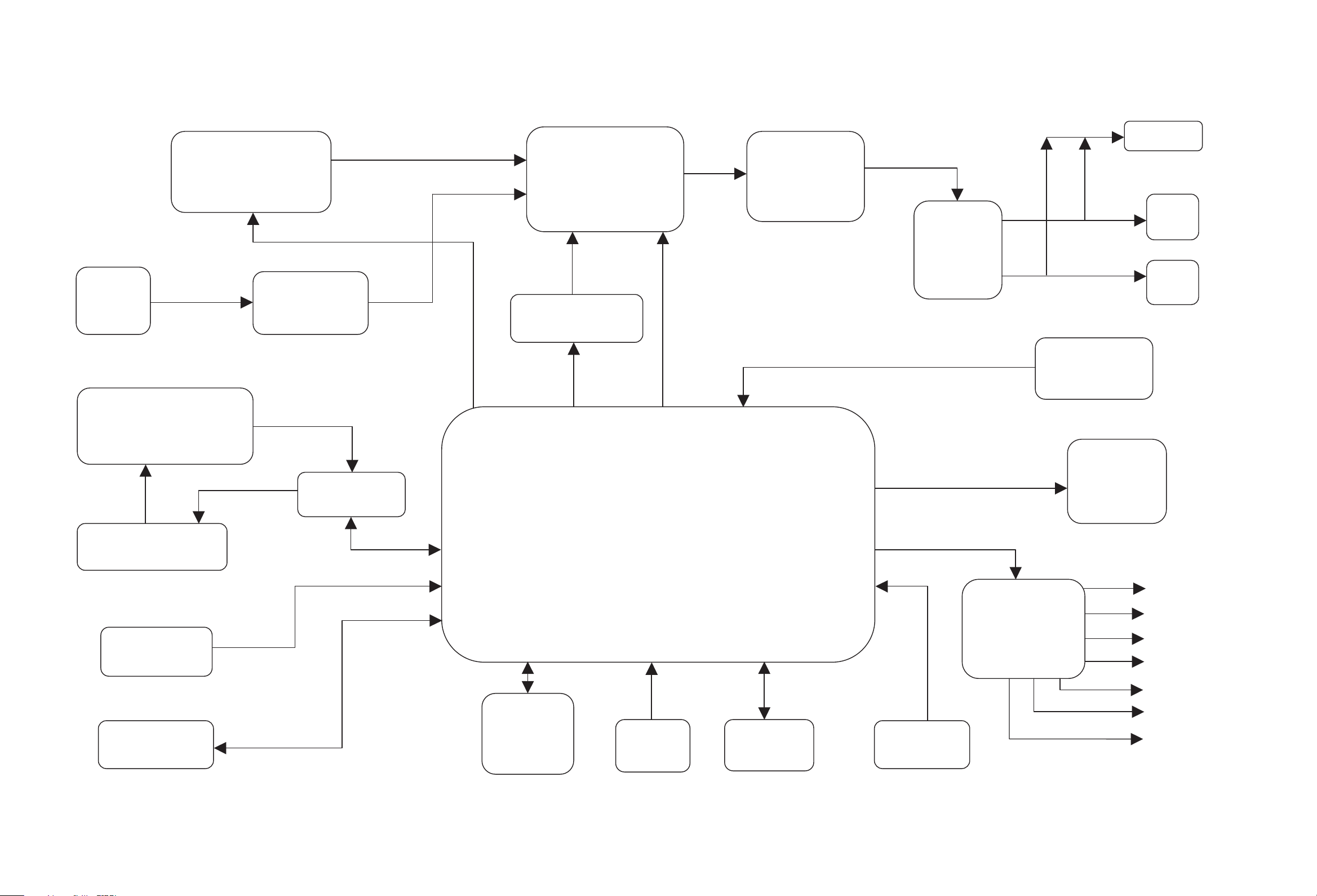
Block diagram
H/P OUT
PC
USB
JK
CD MECHANISM
TUNER Pack
DECODE
CD RF
FUNC
SW+VOL+EQ
D/A CONVERT
AHB_PRO
SP_L
8ohm
POWER
SP_R
8ohm
REMOCON
VFD
TCC760
MOTOR DRIVER
FLASH
SDRAM
MP3/WMA DECODER/ENCODER
DOOR
MOTOR
USB
HOST
EEPROM
KEY
P_CON
P-CD
EXTEND IC
P_TU
P_MUTE
TU_CL
TU_CE
TU_DI
2-1
Page 4
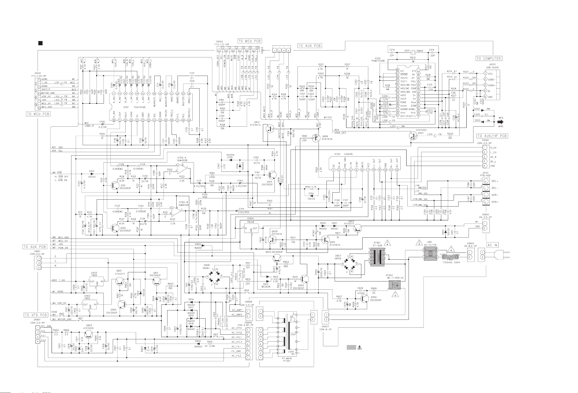
Standard schematic diagrams
Primary & Function control section
2-2
Parts are safety assurance parts.
When replacing those parts make
sure to use the specified one.
Page 5
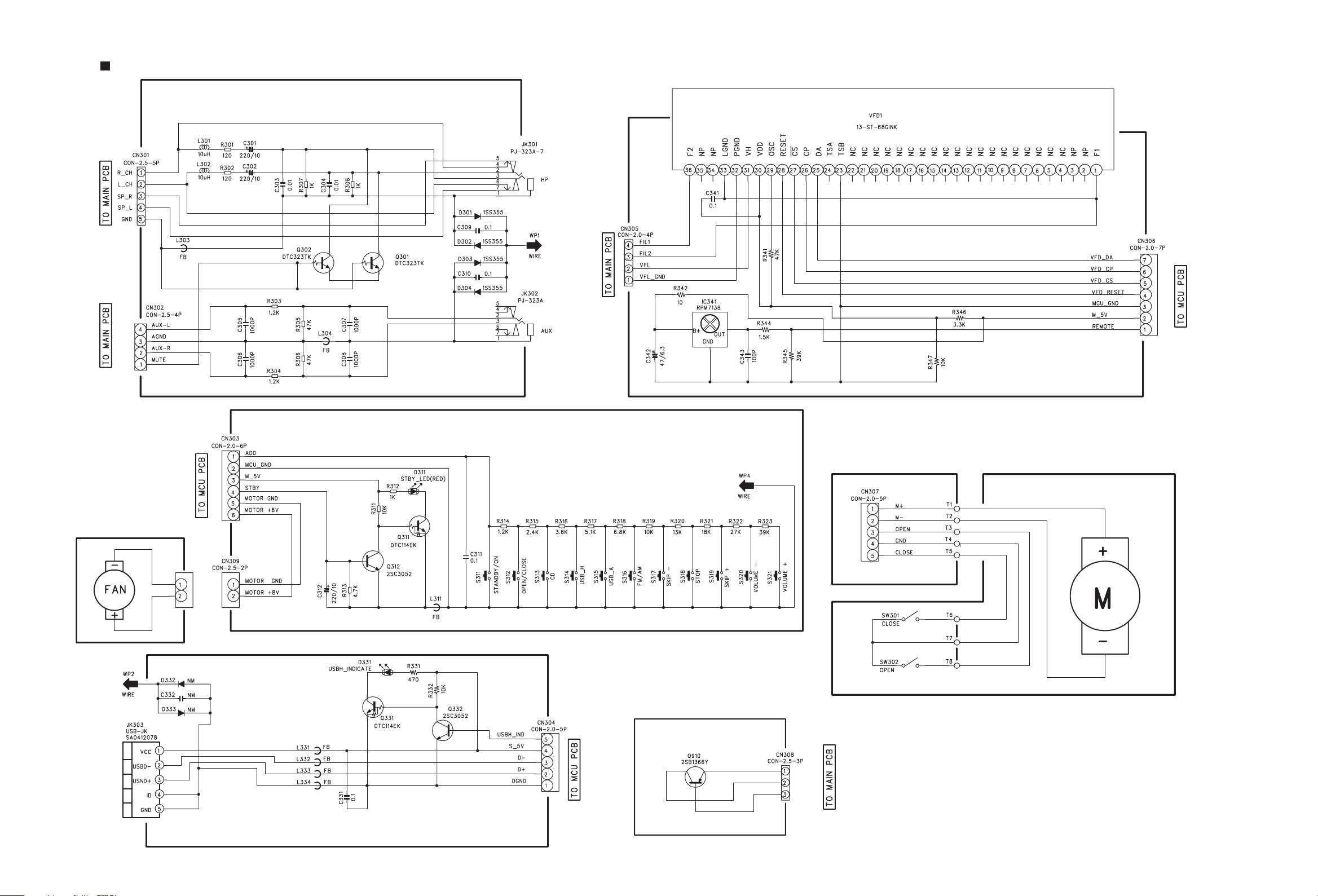
Front section
2-3
Page 6
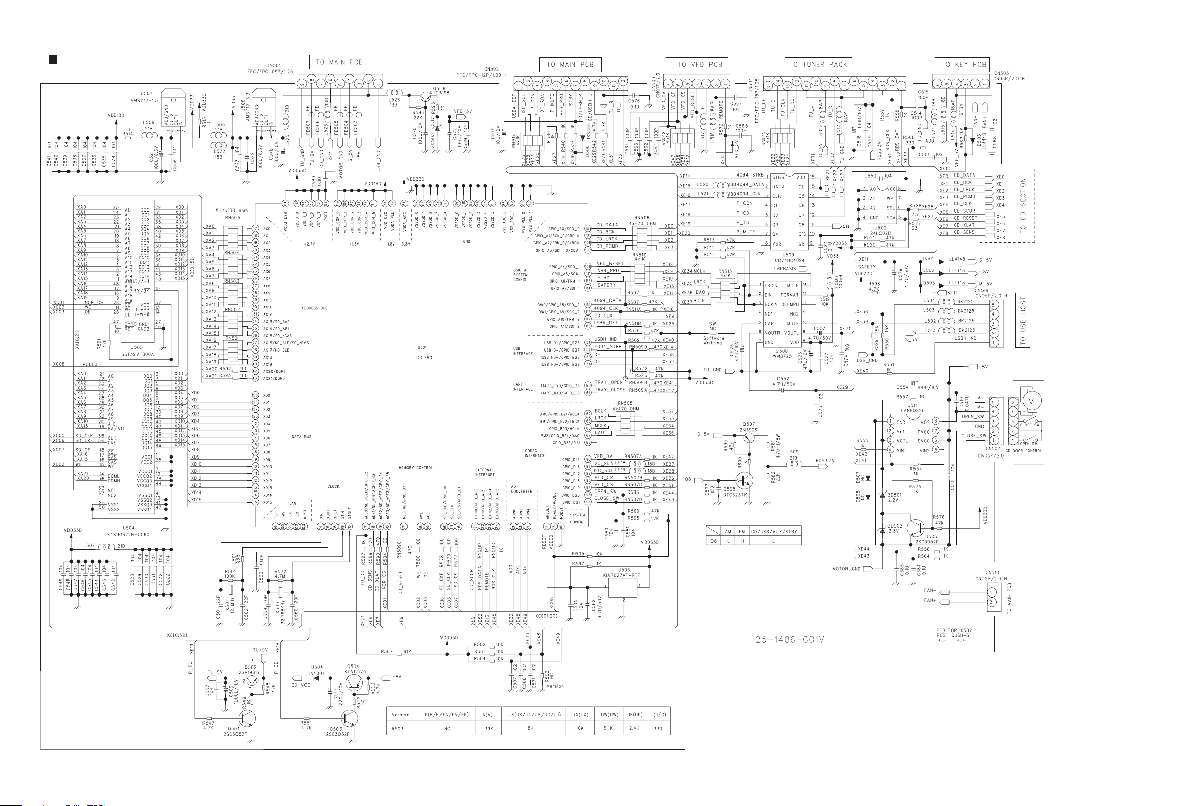
Micon section
2-4
Page 7
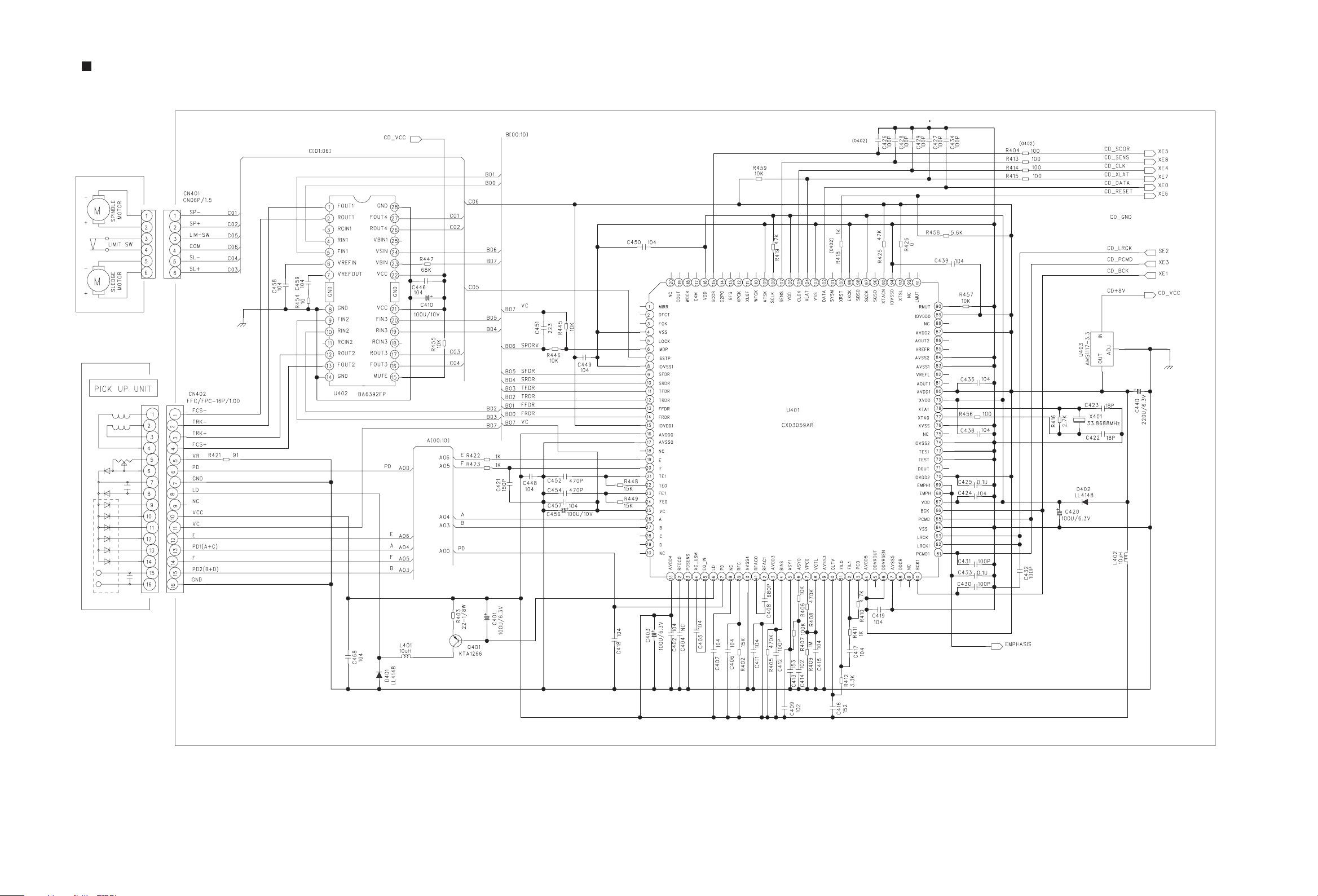
CD servo control section
2-5
Page 8

Printed circuit boards
Main board
Lead free solder used in the board (material : Sn-Ag-Cu, melting point : 219 Centigrade)
(Forward side) (Reverse side)
2-6
Page 9

MCU & CD board
Lead free solder used in the board (material : Sn-Ag-Cu, melting point : 219 Centigrade)
(Forward side)
2-7
Page 10

MCU & CD board
Lead free solder used in the board (material : Sn-Ag-Cu, melting point : 219 Centigrade)
(Reverse side)
2-8
Page 11

< MEMO >
Page 12

Victor Company of Japan, Limited
AV SYSTEMS CATEGORY 10-1,1chome,Ohwatari-machi,Maebashi-city,371-8543,Japan
(No.MB483SCH)
Printed in Japan
VPT
Page 13

PARTS LIST
[ UX-E15 ]
* All printed circuit boards and its assemblies are not available as service parts.
Area suffix
B ------------------------------- U.K.
E ----------- Continental Europe
EN ------------ Northern Europe
EV -------------- Eastern Europe
MB483
- Contents -
Exploded view of general assembly and parts list (Block No.M1)
Electrical parts list (Block No.01~03)
Packing materials and accessories parts list (Block No.M3)
3- 2
3- 4
3-10
3-1
Page 14

Exploded view of general assembly and parts list
Block No.
48
22
19
M
M
1
M
36
30
41
36
32
23
31
58
33
44
44
28
14
14
27
38
14
46
37
48
53
24
25
CD
board
26
29
34
54
52
45
10
14
24
17
21
38
20
53
42
42
35
16
51
51
15
12
11
9
14
14
13
52
8
3-2
Main board
43
43
43
47
40
43
39
40
38
38
55
40
7
38
40
56
7
6
5
39
4
1
40
F902
57
3
Page 15

General Assembly
Symbol No. Part No. Part Name Description Local
1 BI1083090101X1 BOTTOM CABINET
3 BI211011140001 POWER TRANS PT901 230V/50HZ
4 BI211011139001 POWER TRANS PT301
5 BI1083110101X1 USB WINDOW
6 BI1083100101X1 DISPLAY WINDOW
7 BIPT001108P2 TAPPING SCREW 4X8(x4)
8 BI1083080101X1 CENTER CABINET
9 BI1083530101X1 LED HOLDER USB
10 BI1083160101X1 POWER LENS
11 BI1083520101X1 LED HOLDER POWER
12 BI1083170101X1 FL GUIDE
13 BI3023940101X1 PC SHIELD PLATE T=0.5mm
14 BIBT000408S3X1 SCREW 2.6XL8mm(x11)
15 BI1083120101X1 POWER KEY
16 BI1083130101X1 VOL KEY
17 BI1083140101X1 FUNCTION KEY
19 BI2031460101X1 SPRING PLATE
20 BI1083080101X1 CENTER CABINET
21 BI1083150101X1 KEY CONT PLATE
22 BI1083060101X1 CD LID
23 BI2030400101X1 CD COVER LID
24 BI3023030101X1 MECHA DUMPER (x3)
25 BI251011008000 CD MECHANISM KSM-900AAA
26 BI2030410101X1 HEAT SINK
27 BI1083180101X1 GEAR BASE
28 BI1083200101X1 GEAR PULLEY
29 BI2030820101X1 HEAT SINK
30 BI1084010101X1 HT SINK COVER
31 BI1083220101X1 ASSIST GEAR
32 BI1083210101X1 IDLER GEAR
33 BI3023010102X1 TRANSMIT BELT DIA44
34 BI3700161X MOTOR 6V HRD-500C14415
35 BI8RL00301X RELAY DC5V ME-7 005-HSL
36 BIBT000404 SCREW 2.6XL6mm(x4)
37 BIBM000403 SCREW 2.6XL6mm(x2)
38 BIRT000618B2 SCREW RH/TH3X6mm(x5)
39 BI3021040101X1 RUBBER FOOT EVA(x4)
40 BIRT000612B3 SCREW M3XL10(x6)
41 BIBTW001910P2X SCREW N4.5X10(x2)
42 BIPT000616P1X2 SCREW 3XL16MM(x2)
43 BIRT000618B2 SCREW RH/TH3X6mm(x4)
44 BIRT000610B3X2 SCREW 3X10(x5)
45 BIRT000606B2X1 SCREW 3X6
46 BIRT000608S3X1 SCREW 3XL8(x3)
47 BIBT000604S3 SCREW
48 BI3023600102X1 CD RUBBER LTD (x2)
51 BI2031340101X1 CENTER HOLDER (x3)
52 BI2031480101X1 CONTACT SHEET BOTTOM(x2)
53 BI2031390101X1 CONTACT SHEET TOP(x2)
54 BI2031500101X1 USB HOLDER LEFT
55 BI2031510101X1 USB HOLDER RIGHT
56 BI2030420101X1 DISP PWB HLDR
57 BI403341X FUSE F902 315mA 250V
58 BI1401441X POWER CORD B
58 BI1401741X POWER CORD E,EN,EV
Block No. [M][1][M][M]
3-3
Page 16

Electrical parts list
Main board
Block No. [0][1]
Symbol No.
IC101 BI113231X IC TDA7440D
IC102 BI103952V IC BA4558F
IC103 BI116701X IC LA4636
IC201 BI118061V IC PCM2704
IC341 BI115291V IC RPMT138-4
IC902 BI111971X IC KIA7809AP/P
IC903 BI102024X IC KIA7805AP/API
IC904 BI120321X IC ST78L08
Q101 2SC3052 TRANSISTOR BI2SC3052FA013H
Q102 2SC3052 TRANSISTOR BI2SC3052FA013H
Q104 2SC3052 TRANSISTOR BI2SC3052FA013H
Q201 DTC114EK DIGI TRANSISTOR BI2DTC114EKA018
Q301 DTC323TK DIGI TRANSISTOR BI2DTC323TKA011
Q302 DTC323TK DIGI TRANSISTOR BI2DTC323TKA011
Q311 DTC114EK DIGI TRANSISTOR BI2DTC114EKA018
Q312 2SC3052 TRANSISTOR BI2SC3052FA013H
Q331 DTC114EK DIGI TRANSISTOR BI2DTC114EKA018
Q332 2SC3052 TRANSISTOR BI2SC3052FA013H
Q901 KTA1273 TRANSISTOR BI2KTA1273P0008
Q902 2SC3052 TRANSISTOR BI2SC3052FA013H
Q903 KTC3205 TRANSISTOR BI2KTC3205P0008
Q904 2SC3052 TRANSISTOR BI2SC3052FA013H
Q905 2SC3052 TRANSISTOR BI2SC3052FA013H
Q906 DTA114YK DIGI TRANSISTOR BI2DTA114YKA018
Q907 KTA1273 TRANSISTOR BI2KTA1273P0008
Q909 DTC114TK DIGI TRANSISTOR BI2DTC114TKA01
Q910 KTB1366 TRANSISTOR BI2KTB1366Y8
Q911 2SC3052 TRANSISTOR BI2SC3052FA013H
Q912 KTC3205 TRANSISTOR BI2KTC3205P0008
Q913 DTC114TS DIGI TRANSISTOR BI2DTC114TSP002
Q914 DTC114TS DIGI TRANSISTOR BI2DTC114TSP002
D103 1SS133 FR DIODE BI31SS133M000V7
D104 1SS133 FR DIODE BI31SS133M000V7
D105 1SS355 DIODE BI31SS355A0077
D106 1SS355 DIODE BI31SS355A0077
D301 1SS355 DIODE BI31SS355A0077
D302 1SS355 DIODE BI31SS355A0077
D303 1SS355 DIODE BI31SS355A0077
D304 1SS355 DIODE BI31SS355A0077
D311 SLR-342VC3F LED BI2801171V RED
D331 BI2801181V LED
D901 1SS133 FR DIODE BI31SS133M000V7
D902 UZ5.1BSB Z DIODE BI3UZ5.1BSBM000
D903 UZ33BSD Z DIODE BI3UZ33BSDM000
D904 1N4003 DIODE BI31N4003LEM000
D905 1N4001 DIODE BI31N4001M0006
D907 DB102 DIODE BI3DB1021X
D908 GBU6J DIODE BI3GBU6J1V
D912 1SS133 FR DIODE BI31SS133M000V7
D913 MC2838 DIODE BI3M C2838A002
D914 1N4001 DIODE BI31N4001M0006
D915 1N4001 DIODE BI31N4001M0006
D916 1N4001 DIODE BI31N4001M0006
D917 1N4001 DIODE BI31N4001M0006
D918 1SS133 FR DIODE BI31SS133M000V7
D919 UZ8.2BSB Z DIODE BI3UZ82BSBM000V
C101 BICC101500JA04 C CAPACITOR 100pF 50V
C102 BICC101500JA04 C CAPACITOR 100pF 50V
C103 BICE225500MP01 E CAPACITOR 2.2uF 50V
C104 BICE225500MP01 E CAPACITOR 2.2uF 50V
C105 BICE225500MP01 E CAPACITOR 2.2uF 50V
C106 BICE225500MP01 E CAPACITOR 2.2uF 50V
C107 BICE225500MP01 E CAPACITOR 2.2uF 50V
C108 BICE225500MP01 E CAPACITOR 2.2uF 50V
C109 BICE225500MP01 E CAPACITOR 2.2uF 50V
C110 BICE225500MP01 E CAPACITOR 2.2uF 50V
C111 BICE225500MP01 E CAPACITOR 2.2uF 50V
C112 BICE225500MP01 E CAPACITOR 2.2uF 50V
C113 BICC104500KA04 C CAPACITOR 0.1uF 50V
Part No. Part Name Description Local
Symbol No.
C114 BICC104500KA04 C CAPACITOR 0.1uF 50V
C115 BICC104500KA04 C CAPACITOR 0.1uF 50V
C116 BICC104500KA04 C CAPACITOR 0.1uF 50V
C118 BICE107160MP01 E CAPACITOR 100uF 16V
C119 BICC104500KA04 C CAPACITOR 0.1uF 50V
C120 BICE106160MP01 E CAPACITOR 10uF 16V
C121 BICC562500KA04 C CAPACITOR 5600pF 50V
C122 BICC562500KA04 C CAPACITOR 5600pF 50V
C124 BICC105100KA04 C CAPACITOR 1uF 10V
C125 BICE475500MP01 E CAPACITOR 4.7uF 50V
C126 BICE107160MP01 E CAPACITOR 100uF 16V
C127 BICE107160MP01 E CAPACITOR 100uF 16V
C128 BICM683101JP01 M CAPACITOR 0.068uF
C129 BICM563101JP01 M CAPACITOR 0.056uF
C130 BICE226160MP01 E CAPACITOR 22uF 16V
C131 BICE475500MP01 E CAPACITOR 4.7uF 50V
C133 BICM683101JP01 M CAPACITOR 0.068uF
C134 BICM563101JP01 M CAPACITOR 0.056uF
C135 BICE226160MP01 E CAPACITOR 22uF 16V
C136 BICE475500MP01 E CAPACITOR 4.7uF 50V
C138 BICC104500KA04 C CAPACITOR 0.1uF 50V
C140 BICC182500KA04 C CAPACITOR 1800pF
C142 BICC182500KA04 C CAPACITOR 1800pF
C143 BICE225500MP01 E CAPACITOR 2.2uF 50V
C144 BICE225500MP01 E CAPACITOR 2.2uF 50V
C145 BICE337250MP01 E CAPACITOR 330uF
C146 BICC561500JA04 C CAPACITOR 560P 50V
C147 BICC561500JA04 C CAPACITOR 560P 50V
C148 BICE476160MP01 E CAPACITOR 47uF 16V
C151 BICC104500KA04 C CAPACITOR 0.1uF 50V
C152 BICC104500KA04 C CAPACITOR 0.1uF 50V
C153 BICC104500KA04 C CAPACITOR 0.1uF 50V
C154 BICC104500KA04 C CAPACITOR 0.1uF 50V
C155 BICC103500KA04 C CAPACITOR 0.01uF 50V
C156 BICC101500JA04 C CAPACITOR 100pF 50V
C157 BICC101500JA04 C CAPACITOR 100pF 50V
C158 BICC103500KA04 C CAPACITOR 0.01uF 50V
C159 BICC102500KA04 C CAPACITOR 1000pF 50V
C160 BICC102500KA04 C CAPACITOR 1000pF 50V
C161 BICC106100ZA02 C CAPACITOR 10uF 10V
C162 BICC106100ZA02 C CAPACITOR 10uF 10V
C163 BICC105100KA04 C CAPACITOR 1uF 10V
C164 BICE107160MP01 E CAPACITOR 100uF 16V
C166 BICC101500JA04 C CAPACITOR 100pF 50V
C167 BICC101500JA04 C CAPACITOR 100pF 50V
C168 BICH101500KM01 C CAPACITOR 100pF 50V
C169 BICH101500KM01 C CAPACITOR 100pF 50V
C170 BICH104500KM01 C CAPACITOR 0.1uF 50V
C201 BICC122500KA04 C CAPACITOR 1200pF 50V
C202 BICC122500KA04 C CAPACITOR 1200pF 50V
C203 BICC472500KA04 C CAPACITOR 4700pF 50V
C204 BICC472500KA04 C CAPACITOR 4700pF 50V
C205 BICC106063MA03 C CAPACITOR 10uF 6.3V SI
C206 BICC106063MA03 C CAPACITOR 10uF 6.3V SI
C207 BICC223500KA04 C CAPACITOR 0.022uF 50V
C208 BICC223500KA04 C CAPACITOR 0.022uF 50V
C209 BICC105100KA04 C CAPACITOR 1uF 10V
C210 BICT476063MA00 TA CAPACITOR 47uF 6.3V
C211 BICC105100KA04 C CAPACITOR 1uF 10V
C212 BICC105100KA04 C CAPACITOR 1uF 10V
C213 BICC105100KA04 C CAPACITOR 1uF 10V
C214 BICC220500JA04 C CAPACITOR 22pF 50V
C215 BICC220500JA04 C CAPACITOR 22pF 50V
C216 BICC104500KA04 C CAPACITOR 0.1uF 50V
C217 BICC330500JA04 C CAPACITOR 33pF 50V
C218 BICC330500JA04 C CAPACITOR 33pF 50V
C219 BICT476063MA00 TA CAPACITOR 47uF 6.3V
C220 BICC104500KA04 C CAPACITOR 0.1uF 50V
C221 BICC102500KA04 C CAPACITOR 1000pF 50V
C301 BICE227100MP11 E CAPACITOR 220uF 10V
C302 BICE227100MP11 E CAPACITOR 220uF 10V
C303 BICC103500KA04 C CAPACITOR 0.01uF 50V
C304 BICC103500KA04 C CAPACITOR 0.01uF 50V
C305 BICC102500KA04 C CAPACITOR 1000pF 50V
C306 BICC102500KA04 C CAPACITOR 1000pF 50V
C307 BICC102500KA04 C CAPACITOR 1000pF 50V
Part No. Part Name Description Local
3-4
Page 17

Symbol No.
Part No. Part Name Description Local
Symbol No.
Part No. Part Name Description Local
C308 BICC102500KA04 C CAPACITOR 1000pF 50V
C309 BICC104500KA04 C CAPACITOR 0.1uF 50V
C310 BICC104500KA04 C CAPACITOR 0.1uF 50V
C311 BICC104500KA04 C CAPACITOR 0.1uF 50V
C312 BICE227100MP11 E CAPACITOR 220uF 10V
C331 BICC104500KA04 C CAPACITOR 0.1uF 50V
C341 BICC104500KA04 C CAPACITOR 0.1uF 50V
C342 BICT476063MA00 TA CAPACITOR 47uF 6.3V
C343 BICC101500JA04 C CAPACITOR 100pF 50V
C901 BICE227100MP01 E CAPACITOR 220uF 10V
C902 BICC104500KA04 C CAPACITOR 0.1uF 50V
C903 BICE477100MP01 E CAPACITOR 470uF 10V
C904 BICE108160MP01 E CAPACITOR 1000uF 16V
C905 BICC104500KA04 C CAPACITOR 0.1uF 50V
C906 BICC104500KA04 C CAPACITOR 0.1uF 50V
C907 BICE47825MSNY8 E CAPACITOR 4700uF 25V
C908 BICC104500KA04 C CAPACITOR 0.1uF 50V
C909 BICE107160MP01 E CAPACITOR 100uF 16V
C910 BICC104500KA04 C CAPACITOR 0.1uF 50V
C911 BICE47825M6Y1 E CAPACITOR 4700uF 25V
C912 BICC104500KA04 C CAPACITOR 0.1uF 50V
C913 BICC104500KA04 C CAPACITOR 0.1uF 50V
C914 BICE475500MP01 E CAPACITOR 4.7uF 50V
C915 BICC104500KA04 C CAPACITOR 0.1uF 50V
C916 BICE336500MP01 E CAPACITOR 33uF
C917 BICC103500KA04 C CAPACITOR 0.01uF 50V
C918 BICE336500MP01 E CAPACITOR 33uF
C919 BICE336500MP01 E CAPACITOR 33uF
C920 BICC104500KA04 C CAPACITOR 0.1uF 50V
C921 BICC104500KA04 C CAPACITOR 0.1uF 50V
C922 BICC334160ZA04 C CAPACITOR 0.33uF 16V
C923 BICE477100MP01 E CAPACITOR 470uF 10V
C924 BICE22810M E CAPACITOR 2200uF 10V
C925 BICC104500KA04 C CAPACITOR 0.1uF 50V
C926 BICC472500KA04 C CAPACITOR 4700pF 50V
C927 BICC104500KA04 C CAPACITOR 0.1uF 50V
C928 BICC104500KA04 C CAPACITOR 0.1uF 50V
C929 BICC104500KA04 C CAPACITOR 0.1uF 50V
C930 BICC104500KA04 C CAPACITOR 0.1uF 50V
C931 BICC104500KA04 C CAPACITOR 0.1uF 50V
C932 BICE476160MP01 E CAPACITOR 47uF 16V
C933 BICE227100MP01 E CAPACITOR 220uF 10V
C934 BICC104500KA04 C CAPACITOR 0.1uF 50V
C936 BICH103500KM01 C CAPACITOR 0.01uF 50V
Ω
R101 BIRC4720105A00 C RESISTOR 4.7K
R102 BIRC1230105A00 C RESISTOR 12K
R103 BIRC4720105A00 C RESISTOR 4.7K
R104 BIRC1230105A00 C RESISTOR 12K
R105 BIRC1000085M00 C RESISTOR 10
R106 BIRC5620105A00 C RESISTOR 5.6K
R107 BIRC5620105A00 C RESISTOR 5.6K
R110 BIRC2220085M00 C RESISTOR 2.2K
R111 BIRC1000105A00 C RESISTOR 10
R112 BIRC4720105A00 C RESISTOR 4.7K
R113 BIRC4720105A00 C RESISTOR 4.7K
R114 BIRC2240105A00 C RESISTOR 220K
R115 BIRC2220105A00 C RESISTOR 2.2K
R116 BIRC2240105A00 C RESISTOR 220K
R117 BIRC2220105A00 C RESISTOR 2.2K
R118 BIRC8220105A00 C RESISTOR 8.2K
R119 BIRC4720105A00 C RESISTOR 4.7K
R120 BIRC1020105A00 C RESISTOR 1K
R121 BIRC1020105A00 C RESISTOR 1K
R122 BIRC0000105A00 C RESISTOR 0
R123 BIRC2220105A00 C RESISTOR 2.2K
R124 BIRC1040105A00 C RESISTOR 100K
R126 BIRC1030105A00 C RESISTOR 10K
R127 BIRC8220105A00 C RESISTOR 8.2K
R128 BIRC4720105A00 C RESISTOR 4.7K
R129 BIRC1020105A00 C RESISTOR 1K
R130 BIRC1020105A00 C RESISTOR 1K
R131 BIRC0000105A00 C RESISTOR 0
R132 BIRC2220105A00 C RESISTOR 2.2K
R133 BIRC1040105A00 C RESISTOR 100K
R135 BIRC1030105A00 C RESISTOR 10K
R137 BIRC1220105A00 C RESISTOR 1.2K
R139 BIRC1220105A00 C RESISTOR 1.2K
Ω
Ω
Ω
Ω
1/8W
Ω
Ω
Ω
Ω
1/10W
Ω
Ω
Ω
Ω
Ω
Ω
Ω
1/10W
Ω
1/10W
Ω
1/10W
Ω
Ω
Ω
Ω
Ω
1/10W
Ω
1/10W
Ω
1/10W
Ω
Ω
Ω
Ω
1/10W
1/10W
1/10W
1/10W
1/10W
1/10W
1/8W
1/10W
1/10W
Ω
1/10W
1/10W
Ω
1/10W
1/10W
1/10W
1/10W
1/10W
Ω
1/10W
1/10W
1/10W
1/10W
1/10W
Ω
1/10W
1/10W
1/10W
1/10W
R140 BIRC1020105A00 C RESISTOR 1KΩ 1/10W
R141 BIRC1020105A00 C RESISTOR 1K
R144 BIRC4720105A00 C RESISTOR 4.7K
R146 BIRC0220105A00 C RESISTOR 2.2
R147 BIRC0220105A00 C RESISTOR 2.2
R148 BIRC0220105A00 C RESISTOR 2.2
R149 BIRC0220105A00 C RESISTOR 2.2
R152 BIRC2220105A00 C RESISTOR 2.2K
R153 BIRC1020105A00 C RESISTOR 1K
R154 BIRC4720105A00 C RESISTOR 4.7K
R155 BIRC1020105A00 C RESISTOR 1K
R156 BIRC4720105A00 C RESISTOR 4.7K
R157 BIRC4720105A00 C RESISTOR 4.7K
R158 BIRC1030105A00 C RESISTOR 10K
R159 BIRC4720105A00 C RESISTOR 4.7K
R160 BIRC1030105A00 C RESISTOR 10K
R165 BIRC2240105A00 C RESISTOR 220K
R166 BIRC2240105A00 C RESISTOR 220K
R167 BIRC1020105A00 C RESISTOR 1K
R168 BIRC6840105A00 C RESISTOR 680K
R169 BIRC4720105A00 C RESISTOR 4.7K
R201 BIRC4720105A00 C RESISTOR 4.7K
R202 BIRC5630105A00 C RESISTOR 56K
R203 BIRC4720105A00 C RESISTOR 4.7K
R204 BIRC5630105A00 C RESISTOR 56K
R205 BIRC1030105A00 C RESISTOR 10K
R206 BIRC1030105A00 C RESISTOR 10K
R207 BIRC1020105A00 C RESISTOR 1K
R208 BIRC1020105A00 C RESISTOR 1K
R209 BIRC3310105A00 C RESISTOR 330
R210 BIRC1800105A00 C RESISTOR 18
R211 BIRC3310105A00 C RESISTOR 330
R212 BIRC1800105A00 C RESISTOR 18
R213 BIRC1050105A00 C RESISTOR 1M
R214 BIRC3300105A00 C RESISTOR 33
R215 BIRC2200105A00 C RESISTOR 22
R216 BIRC1520105A00 C RESISTOR 1.5K
R217 BIRC2200105A00 C RESISTOR 22
R220 BIRC1030105A00 C RESISTOR 10K
R221 BIRC0000105A00 C RESISTOR 0
R222 BIRC1010105A00 C RESISTOR 100
R223 BIRC1010105A00 C RESISTOR 100
R224 BIRC0000105A00 C RESISTOR 0
R225 BIRC0000105A00 C RESISTOR 0
R226 BIRC0000105A00 C RESISTOR 0
R227 BIRC1010105A00 C RESISTOR 100
R228 BIRC1010105A00 C RESISTOR 100
R229 BIRC1010105A00 C RESISTOR 100
R301 BIRC1210105A00 C RESISTOR 120
R302 BIRC1210105A00 C RESISTOR 120
R303 BIRC1220105A00 C RESISTOR 1.2K
R304 BIRC1220105A00 C RESISTOR 1.2K
R305 BIRC4730105A00 C RESISTOR 47K
R306 BIRC4730105A00 C RESISTOR 47K
R307 BIRC1020105A00 C RESISTOR 1K
R308 BIRC1020105A00 C RESISTOR 1K
R311 BIRC1030105A00 C RESISTOR 10K
R312 BIRC1020105A00 C RESISTOR 1K
R313 BIRC4720105A00 C RESISTOR 4.7K
R314 BIRC1220105A00 C RESISTOR 1.2K
R315 BIRC2420105A00 C RESISTOR 2.4K
R316 BIRC3620105A00 C RESISTOR 3.6K 1/10W
R317 BIRC5120105A00 C RESISTOR 5.1K
R318 BIRC6820105A00 C RESISTOR 6.8K
R319 BIRC1030105A00 C RESISTOR 10K
R320 BIRC1330105A00 C RESISTOR 13K
R321 BIRC1830105A00 C RESISTOR 18K
R322 BIRC2730105A00 C RESISTOR 27K
R323 BIRC3930105A00 C RESISTOR 39K
R331 BIRC4710105A00 C RESISTOR 470
R332 BIRC1030105A00 C RESISTOR 10K
R341 BIRC4730105A00 C RESISTOR 47K
R342 BIRC1000105A00 C RESISTOR 10
R344 BIRC1520105A00 C RESISTOR 1.5K
R345 BIRC3930105A00 C RESISTOR 39K
R346 BIRC3320105A00 C RESISTOR 3.3K
R347 BIRC1030105A00 C RESISTOR 10K
R901 BIRC1020105A00 C RESISTOR 1K
Ω
Ω
Ω
Ω
Ω
Ω
Ω
Ω
Ω
Ω
Ω
Ω
Ω
Ω
Ω
Ω
Ω
Ω
1/10W
Ω
Ω
1/10W
Ω
Ω
1/10W
Ω
1/10W
Ω
1/10W
Ω
Ω
1/10W
Ω
Ω
Ω
1/10W
Ω
1/10W
Ω
1/10W
Ω
Ω
Ω
Ω
Ω
Ω
Ω
Ω
Ω
Ω
Ω
Ω
Ω
Ω
Ω
Ω
Ω
Ω
Ω
Ω
1/10W
Ω
Ω
Ω
1/10W
Ω
1/10W
1/10W
1/10W
1/10W
1/10W
Ω
1/10W
1/10W
Ω
1/10W
1/10W
Ω
1/10W
Ω
1/10W
1/10W
Ω
1/10W
1/10W
Ω
1/10W
Ω
1/10W
1/10W
Ω
1/10W
Ω
1/10W
Ω
1/10W
1/10W
Ω
1/10W
1/10W
1/10W
1/10W
1/10W
1/10W
1/10W
1/10W
1/10W
Ω
1/10W
1/10W
1/10W
1/10W
1/10W
1/10W
1/10W
1/10W
1/10W
Ω
1/10W
Ω
1/10W
1/10W
1/10W
1/10W
1/10W
1/10W
1/10W
Ω
1/10W
Ω
1/10W
Ω
1/10W
Ω
1/10W
Ω
1/10W
1/10W
1/10W
1/10W
1/10W
1/10W
1/10W
1/10W
1/10W
Ω
1/10W
1/10W
Ω
1/10W
1/10W
1/10W
3-5
Page 18

Symbol No.
Part No. Part Name Description Local
Symbol No.
Part No. Part Name Description Local
R902 BIRC4720085M00 C RESISTOR 4.7KΩ 1/8W J C
R903 BIRC1030105A00 C RESISTOR 10K
R904 BIRC0220085M00 C RESISTOR 2.2
R905 BIRC0220085M00 C RESISTOR 2.2
R906 BIRC4710105A00 C RESISTOR 470
R907 BIRC4720105A00 C RESISTOR 4.7K
R908 BIRC4720105A00 C RESISTOR 4.7K
R909 BIRC3300085M00 C RESISTOR 33
R910 BIRC3300045M00 C RESISTOR 33
R911 BIRC2230105A00 C RESISTOR 22K
R912 BIRC2230105A00 C RESISTOR 22K
R913 BIRC2220105A00 C RESISTOR 2.2K
R914 BIRC1030105A00 C RESISTOR 10K
R915 BIRC1020105A00 C RESISTOR 1K
R916 BIRC2230105A00 C RESISTOR 22K
R917 BIRC1020105A00 C RESISTOR 1K
R918 BIRC1030105A00 C RESISTOR 10K
R919 BIRC3910105A00 C RESISTOR 390
R920 BIRC1220105A00 C RESISTOR 1.2K
R921 BIRC1030105A00 C RESISTOR 10K
R922 BIRC6810105A00 C RESISTOR 680
R923 BIRC3910045M00 C RESISTOR 390
L101 BI18A843556N00 FILTER BEAD 843556
L102 BI18A843556N00 FILTER BEAD 843556
L103 BI18A843556N00 FILTER BEAD 843556
L104 BI18A843556N00 FILTER BEAD 843556
L108 BI26BLM21BA000 COIL BLM21B272S
L109 BI26BLM21BA000 COIL BLM21B272S
L110 BI26BLM21BA000 COIL BLM21B272S
L111 BI26BLM21BA000 COIL BLM21B272S
L112 BI26BLM21BA000 COIL BLM21B272S
L113 BI26BLM21BA000 COIL BLM21B272S
L114 BI26BLM21BA000 COIL BLM21B272S
L115 BI26BLM21BA000 COIL BLM21B272S
L116 BI2600702V CHOKE COIL 1uH
L117 BI2600702V CHOKE COIL 1uH
L118 BI2600702V CHOKE COIL 1uH
L119 BI2600702V CHOKE COIL 1uH
L202 BI26BLM21BA000 COIL BLM21B272S
L203 BI26BLM21BA000 COIL BLM21B272S
L205 BI26BLM21BA000 COIL BLM21B272S
L206 BI26BLM21BA000 COIL BLM21B272S
L210 BI26BLM21BA000 COIL BLM21B272S
L301 BI26100000KA00 CHOKE COIL
L302 BI26100000KA00 CHOKE COIL
L303 BI18A843556N00 FILTER BEAD 843556
L304 BI26BLM21BA000 COIL BLM21B272S
L311 BI26BLM21BA000 COIL BLM21B272S
L331 BI18A601TRA002 FERRITE BEAD 600
L332 BI18A601TRA002 FERRITE BEAD 600
L333 BI18A601TRA002 FERRITE BEAD 600
L334 BI18A601TRA002 FERRITE BEAD 600
L901 BI2601102V LINE FILTER WIRE
CN101 BI12S90024V FFC CONNECTOR 9P
CN102 BI12S120044 CONNECTOR 12P
CN103 BI12S40080V CONNECTOR 4P
CN104 BI12S50159V SOCKET 5P
CN301 BI12P50170X CONNECTOR WIRE 5P for MAIN CN104
CN302 BI12P40313Y CONNECTOR WIRE 4P for MAIN CN103
CN303 BI12P60177X CONNECTOR WIRE 6P for CD CN505
CN304 BI12P50171Y CONNECTOR WIRE 5P for USB CN506
CN305 BI12P40305X CONNECTOR WIRE 4P for MAIN CN901
CN306 BI12P70108X CONNECTOR WIRE 7P for MAIN CN503
CN307 BI12P50169X CONNECTOR WIRE 5P for CD CN507
CN308 BI12P30265X CONNECTOR WIRE 3P
CN901 BI12S400551 CONNECTOR 4P
CN902 BI12S200691V CONNECTOR 2P
CN907 BI12S200691V CONNECTOR 2P
CN908 BI12S200801X CONNECTOR 2P
CN909 BI12S700491X CONNECTOR 7P
CN910 BI12P20236X CONNECTOR WIRE 2P for CD CN510
CN911 BI12S300471V CONNECTOR 3P
J201 BIRC0000085A00 C RESISTOR 0
J202 BIRC0000085A00 C RESISTOR 0
Ω
1/10W
Ω
1/8W
Ω
1/8W
Ω
1/10W
Ω
1/10W
Ω
1/10W
Ω
1/8W
Ω
1/4W
Ω
1/10W
Ω
1/10W
Ω
1/10W
Ω
1/10W
Ω
1/10W
Ω
1/10W
Ω
1/10W
Ω
1/10W
Ω
1/10W
Ω
1/10W
Ω
1/10W
Ω
1/10W
Ω
1/4W
10uH K
SDFL1608S10
10uH K
SDFL1608S10
Ω
Ω
Ω
Ω
Ω
1/8W
Ω
1/8W
J203 BIRC0000085A00 C RESISTOR 0Ω 1/8W
J204 BIRC0000085A00 C RESISTOR 0
J205 BIRC0000085A00 C RESISTOR 0
J206 BIRC0000085A00 C RESISTOR 0
J207 BIRC0000085A00 C RESISTOR 0
J208 BIRC0000085A00 C RESISTOR 0
J209 BIRC0000085A00 C RESISTOR 0
J210 BIRC0000085A00 C RESISTOR 0
J212 BIRC0000105A00 C RESISTOR 0
J214 BIRC0000105A00 C RESISTOR 0
J215 BIRC0000105A00 C RESISTOR 0
J216 BIRC0000105A00 C RESISTOR 0
J221 BIRC0000105A00 C RESISTOR 0
J2113 BIRC0000105A00 C RESISTOR 0
JK101 BI2301252V SPK TERMINAL 4P
JK201 BI23B1561V USB CONNECTORS 6P
JK301 BI23B0293V HEADPHONE JACK PJ-310HB
JK302 BI23B0293V HEADPHONE JACK PJ-310HB
JK303 BI23B1621V USB A/F
PR903 BI44001125N000 FUSE PROTECTOR 4A 125V 52
PR904 BI42501125N000 FUSE PROTECTOR 2.5A 125V
RT901 BIRT103THMSP01 THERMISTOR 10K
RY901 BI8RL00301X RELAY
S311 BI8SKRGAED0P0 TACT SWITCH SKRGAED010
S312 BI8SKRGAED0P0 TACT SWITCH SKRGAED010
S313 BI8SKRGAED0P0 TACT SWITCH SKRGAED010
S314 BI8SKRGAED0P0 TACT SWITCH SKRGAED010
S315 BI8SKRGAED0P0 TACT SWITCH SKRGAED010
S316 BI8SKRGAED0P0 TACT SWITCH SKRGAED010
S317 BI8SKRGAED0P0 TACT SWITCH SKRGAED010
S318 BI8SKRGAED0P0 TACT SWITCH SKRGAED010
S319 BI8SKRGAED0P0 TACT SWITCH SKRGAED010
S320 BI8SKRGAED0P0 TACT SWITCH SKRGAED010
S321 BI8SKRGAED0P0 TACT SWITCH SKRGAED010
SW301 BI805331X LIMIT SWITCH SPPB6A0100
SW302 BI805341X LIMIT SWITCH SPPB6A0400
VFD1 BI2702321X VFD 13-ST-68GINK
X201 BI2102391V CRYSTAL 12MHz
XXXXX BI1207111X FLAT CABLE 3P E1 to E2
XXXXX BI1207111X FLAT CABLE 3P F1 to F2
XXXXX BI1207111X FLAT CABLE 3P G1 to G2
XXXXX BIRT000608B31 SCREW 3xL8mm
XXXXX BI2029330101X2 HEAT RES BKT
XXXXX BI3023670101X1 FILTER PCT=0.5
XXXXX BI2030410101X1 HEAT SINK A1100
XXXXX BI11AT050M02X WIRE ASSY
XXXXX BI2026400201X1 METAL SHEET PLATING(x2)
XXXXX BI2031470101X1 METAL BLOCK
XXXXX BIRT000608B3X1 SCREW 3xL8mm(x2)
Ω
1/8W
Ω
1/8W
Ω
1/8W
Ω
1/8W
Ω
1/8W
Ω
1/8W
Ω
1/8W
Ω
1/10W
Ω
1/10W
Ω
1/10W
Ω
1/10W
Ω
1/10W
Ω
1/10W
DC 5V ME-7 005HSL
TRANS/MAINPCB/
AUXPCB(x2)
CD board
Block No. [0][2]
Symbol No.
U401 BI116751X IC CXD3059AR
U402 BI113991X IC BA6392FP
U403 BI111501V IC AMS1117-3.3
U5 01 B I11 9111V IC TCC 760
U502 BI111731X IC 24LC02B
U503 BI120391X IC KIA7027AF-RTF
U504 BI117401V IC K4S161622H-uc60
U505 BI115441V IC SST39VF800A
U506 BI111501V IC AMS1117-3.3
U507 BI120161X IC LM1117-1.5
U508 BI111751X IC WM8725GED
U509 BI119711X IC CD74HC4094M
U511 BI118681X IC FAN8082D
Q401 KTA1266GR TRANSISTOR BI2KTA1266GP00
Q501 2SC3052 TRANSISTOR BI2SC3052FA013H
Q502 2SA1981Y TRANSISTOR BI2SA1981YP000
Q503 2SC3052 TRANSISTOR BI2SC3052FA013H
Part No. Part Name Description Local
3-6
Page 19

Symbol No.
Part No. Part Name Description Local
Symbol No.
Part No. Part Name Description Local
Q504 KTA1273 TRANSISTOR BI2KTA1273P0008
Q505 2SC3052 TRANSISTOR BI2SC3052FA013H
Q506 KTC3198GR/P TRANSISTOR BI2KTC3198GP00
Q507 2N3906 TRANSISTOR BI2N3906A0000
Q508 DTC323TK DIGI TRANSISTOR BI2DTC323TKA011
D401 LL4148 SWITCH DIODE BI3LL4148A018
D402 LL4148 SWITCH DIODE BI3LL4148A018
D501 LL4148 SWITCH DIODE BI3LL4148A018
D502 LL4148 SWITCH DIODE BI3LL4148A018
D503 LL4148 SWITCH DIODE BI3LL4148A018
D504 1N4001 DIODE BI31N4001M0006
D505 LL4148 SWITCH DIODE BI3LL4148A018
D506 1SS355 DIODE BI31SS355A0077
ZD501 MTZJ2.2B Z DIODE BI3MTZJ2.2BM000
ZD502 MTZJ3.3B Z DIODE BI3MTZJ33BM000V
ZD503 UZ5.1BSB Z DIODE BI3UZ5.1BSBM000
C401 BICE107063MP11 E CAPACITOR 100uF 6.3V
C402 BICC104500KA04 C CAPACITOR 0.1uF 50V
C403 BICE107063MP11 E CAPACITOR 100uF 6.3V
C405 BICC104500KA04 C CAPACITOR 0.1uF 50V
C406 BICC104500KA04 C CAPACITOR 0.1uF 50V
C407 BICC104500KA04 C CAPACITOR 0.1uF 50V
C408 BICC681500JA04 C CAPACITOR 680pF 50V
C409 BICC102500KA04 C CAPACITOR 1000pF 50V
C410 BICE107100MP11 E CAPACITOR 100uF 10V
C411 BICC104500KA04 C CAPACITOR 0.1uF 50V
C412 BICC101500JA04 C CAPACITOR 100pF 50V
C413 BICC153500KA04 C CAPACITOR 0.015uF 50V
C414 BICC102500KA04 C CAPACITOR 1000pF 50V
C415 BICC104500KA04 C CAPACITOR 0.1uF 50V
C416 BICC152500KA04 C CAPACITOR 1500pF 50V
C417 BICC104500KA04 C CAPACITOR 0.1uF 50V
C418 BICC104500KA04 C CAPACITOR 0.1uF 50V
C419 BICC104500KA04 C CAPACITOR 0.1uF 50V
C420 BICE107063MP11 E CAPACITOR 100uF 6.3V
C421 BICC151500JA04 C CAPACITOR 150pF 50V
C422 BICC180500JA04 C CAPACITOR 18pF 50V
C423 BICC180500JA04 C CAPACITOR 18pF 50V
C424 BICC104500KA04 C CAPACITOR 0.1uF 50V
C425 BICC104100KA04 C CAPACITOR 0.1uF 10V
C426 BICC101500JA04 C CAPACITOR 100pF 50V
C427 BICC101500JA04 C CAPACITOR 100pF 50V
C428 BICC101500JA04 C CAPACITOR 100pF 50V
C429 BICC101500JA04 C CAPACITOR 100pF 50V
C430 BICC101500JA04 C CAPACITOR 100pF 50V
C431 BICC101500JA04 C CAPACITOR 100pF 50V
C432 BICC101500JA04 C CAPACITOR 100pF 50V
C433 BICC104100KA04 C CAPACITOR 0.1uF 10V
C434 BICC101500JA04 C CAPACITOR 100pF 50V
C435 BICC104500KA04 C CAPACITOR 0.1uF 50V
C438 BICC104500KA04 C CAPACITOR 0.1uF 50V
C439 BICC104500KA04 C CAPACITOR 0.1uF 50V
C440 BICE227063MP11 E CAPACITOR 220uF 6.3V
C444 BICE227100MP11 E CAPACITOR 220uF 10V
C446 BICC104500KA04 C CAPACITOR 0.1uF 50V
C448 BICC104500KA04 C CAPACITOR 0.1uF 50V
C449 BICC104500KA04 C CAPACITOR 0.1uF 50V
C450 BICC104500KA04 C CAPACITOR 0.1uF 50V
C451 BICC223500KA04 C CAPACITOR 0.022uF 50V
C452 BICC471500JA04 C CAPACITOR 470pF
C454 BICC471500JA04 C CAPACITOR 470pF
C456 BICE107100MP01 E CAPACITOR 100uF 10V
C457 BICC104500KA04 C CAPACITOR 0.1uF 50V
C458 BICC104500KA04 C CAPACITOR 0.1uF 50V
C459 BICC104500KA04 C CAPACITOR 0.1uF 50V
C468 BICC104500KA04 C CAPACITOR 0.1uF 50V
C501 BICC220500JA04 C CAPACITOR 22pF 50V
C502 BICC220500JA04 C CAPACITOR 22pF 50V
C503 BICC331500KA04 C CAPACITOR 330pF 50V
C504 BICC104500KA04 C CAPACITOR 0.1uF 50V
C505 BICC102500KA04 C CAPACITOR 1000pF 50V
C506 BICC102500KA04 C CAPACITOR 1000pF 50V
C507 BICC102500KA04 C CAPACITOR 1000pF 50V
C509 BICE108100MP01 E CAPACITOR 1000uF 10V
C510 BICC473500KA04 C CAPACITOR 0.047uF 50V
C511 BICC104500KA04 C CAPACITOR 0.1uF 50V
C514 BICC101500JA04 C CAPACITOR 100pF 50V
C515 BICC101500JA04 C CAPACITOR 100pF 50V
C518 BICE107100MP01 E CAPACITOR 100uF 10V
C521 BICE107063MP11 E CAPACITOR 100uF 6.3V
C522 BICE107063MP11 E CAPACITOR 100uF 6.3V
C523 BICC104500KA04 C CAPACITOR 0.1uF 50V
C524 BICC104100KA04 C CAPACITOR 0.1uF 10V
C525 BICE476100MP11 E CAPACITOR 47uF 10V
C526 BICE476100MP11 E CAPACITOR 47uF 10V
C527 BICC104500KA04 C CAPACITOR 0.1uF 50V
C528 BICC104500KA04 C CAPACITOR 0.1uF 50V
C529 BICC104500KA04 C CAPACITOR 0.1uF 50V
C530 BICC104500KA04 C CAPACITOR 0.1uF 50V
C531 BICC104500KA04 C CAPACITOR 0.1uF 50V
C532 BICC104500KA04 C CAPACITOR 0.1uF 50V
C533 BICC104500KA04 C CAPACITOR 0.1uF 50V
C534 BICC104500KA04 C CAPACITOR 0.1uF 50V
C535 BICC104500KA04 C CAPACITOR 0.1uF 50V
C536 BICC104500KA04 C CAPACITOR 0.1uF 50V
C537 BICC104500KA04 C CAPACITOR 0.1uF 50V
C538 BICC104500KA04 C CAPACITOR 0.1uF 50V
C539 BICC104500KA04 C CAPACITOR 0.1uF 50V
C540 BICC104500KA04 C CAPACITOR 0.1uF 50V
C541 BICC104500KA04 C CAPACITOR 0.1uF 50V
C542 BICC104500KA04 C CAPACITOR 0.1uF 50V
C543 BICC104500KA04 C CAPACITOR 0.1uF 50V
C544 BICC104500KA04 C CAPACITOR 0.1uF 50V
C545 BICC104500KA04 C CAPACITOR 0.1uF 50V
C546 BICC104500KA04 C CAPACITOR 0.1uF 50V
C547 BICC104500KA04 C CAPACITOR 0.1uF 50V
C548 BICC104500KA04 C CAPACITOR 0.1uF 50V
C549 BICC104500KA04 C CAPACITOR 0.1uF 50V
C550 BICC104500KA04 C CAPACITOR 0.1uF 50V
C552 BICE475500MP11 E CAPACITOR 4.7uF 50V
C553 BICE475500MP11 E CAPACITOR 4.7uF 50V
C554 BICE107100MP11 E CAPACITOR 100uF 10V
C555 BICC104500KA04 C CAPACITOR 0.1uF 50V
C556 BICC104500KA04 C CAPACITOR 0.1uF 50V
C557 BICC104500KA04 C CAPACITOR 0.1uF 50V
C559 BICC200500JA04 C CAPACITOR 20pF 50V
C560 BICC200500JA04 C CAPACITOR 20pF 50V
C561 BICC101500JA04 C CAPACITOR 100pF 50V
C562 BICC101500JA04 C CAPACITOR 100pF 50V
C563 BICC101500JA04 C CAPACITOR 100pF 50V
C564 BICC101500JA04 C CAPACITOR 100pF 50V
C565 BICC101500JA04 C CAPACITOR 100pF 50V
C567 BICC102500KA04 C CAPACITOR 1000pF 50V
C568 BICC102500KA04 C CAPACITOR 1000pF 50V
C569 BICC104500KA04 C CAPACITOR 0.1uF 50V
C570 BICE107100MP11 E CAPACITOR 100uF 10V
C571 BICC102500KA04 C CAPACITOR 1000pF 50V
C572 BICE107100MP11 E CAPACITOR 100uF 10V
C573 BICC102500KA04 C CAPACITOR 1000pF 50V
C574 BICC102500KA04 C CAPACITOR 1000pF 50V
C575 BICT106100MA00 TA CAPACITOR 10uF 10V
C576 BICC104500KA04 C CAPACITOR 0.1uF 50V
C577 BICC102500KA04 C CAPACITOR 1000pF 50V
C578 BICE107100MP11 E CAPACITOR 100uF 10V
C579 BICE475500MP11 E CAPACITOR 4.7uF 50V
C580 BICC104500KA04 C CAPACITOR 0.1uF 50V
C581 BICC104500KA04 C CAPACITOR 0.1uF 50V
C582 BICE475500MP11 E CAPACITOR 4.7uF 50V
C583 BICC104100KA04 C CAPACITOR 0.1uF 10V
C584 BICC104100KA04 C CAPACITOR 0.1uF 10V
C585 BICC104100KA04 C CAPACITOR 0.1uF 10V
Ω
R402 BIRC1530105A00 C RESISTOR 15K
R403 BIRC2200085A00 C RESISTOR 22
R404 BIRC1010105A00 C RESISTOR 100
R405 BIRC4740105A00 C RESISTOR 470K
R406 BIRC1030105A00 C RESISTOR 10K
R407 BIRC1040105A00 C RESISTOR 100K
R408 BIRC4740105A00 C RESISTOR 470K
R409 BIRC1050105A00 C RESISTOR 1M
R410 BIRC4720105A00 C RESISTOR 4.7K
R411 BIRC1020105A00 C RESISTOR 1K
R412 BIRC3320105A00 C RESISTOR 3.3K
R413 BIRC1010105A00 C RESISTOR 100
Ω
1/8W
Ω
Ω
Ω
1/10W
Ω
Ω
1/10W
Ω
Ω
1/10W
1/10W
Ω
1/10W
1/10W
Ω
1/10W
Ω
1/10W
1/10W
1/10W
1/10W
3-7
Page 20

Symbol No.
Part No. Part Name Description Local
Symbol No.
Part No. Part Name Description Local
R414 BIRC1010105A00 C RESISTOR 100Ω 1/10W
R415 BIRC1010105A00 C RESISTOR 100
R416 BIRC2720105A00 C RESISTOR 2.7K
R418 BIRC1020165A00 C RESISTOR 1K
R419 BIRC4730105A00 C RESISTOR 47K
R421 BIRC9100105A00 C RESISTOR 91
R422 BIRC1020105A00 C RESISTOR 1K
R423 BIRC1020105A00 C RESISTOR 1K
R425 BIRC4730105A00 C RESISTOR 47K
R426 BIRC0000105A00 C RESISTOR 0
R445 BIRC1030105A00 C RESISTOR 10K
R446 BIRC1030105A00 C RESISTOR 10K
R447 BIRC6830105A00 C RESISTOR 68K
R448 BIRC1530105A00 C RESISTOR 15K
R449 BIRC1530105A00 C RESISTOR 15K
R454 BIRC1000105A00 C RESISTOR 10
R455 BIRC1030105A00 C RESISTOR 10K
R456 BIRC1010105A00 C RESISTOR 100
R457 BIRC1030105A00 C RESISTOR 10K
R458 BIRC5620105A00 C RESISTOR 5.6K
R459 BIRC1030105A00 C RESISTOR 10K
R501 BIRC1040165A00 C RESISTOR 100K
R502 BIRC1030105A00 C RESISTOR 10K
R504 BIRC1030105A00 C RESISTOR 10K
R505 BIRC1030105A00 C RESISTOR 10K
R507 BIRC4730105A00 C RESISTOR 47K
R509 BIRC4730105A00 C RESISTOR 47K
R511 BIRC4730105A00 C RESISTOR 47K
R512 BIRC4730105A00 C RESISTOR 47K
R513 BIRC4730105A00 C RESISTOR 47K
R514 BIRC0000085A00 C RESISTOR 0
R515 BIRC0000085A00 C RESISTOR 0
R519 BIRC1030105A00 C RESISTOR 10K
R520 BIRC4730105A00 C RESISTOR 47K
R521 BIRC4730105A00 C RESISTOR 47K
R522 BIRC4730105A00 C RESISTOR 47K
R523 BIRC4730105A00 C RESISTOR 47K
R526 BIRC4730105A00 C RESISTOR 47K
R527 BIRC3300105A00 C RESISTOR 33
R528 BIRC3300105A00 C RESISTOR 33
R529 BIRC1530105A00 C RESISTOR 15K
R530 BIRC1530105A00 C RESISTOR 15K
R531 BIRC1020105A00 C RESISTOR 1K
R532 BIRC1020105A00 C RESISTOR 1K
R537 BIRC1020105A00 C RESISTOR 1K
R540 BIRC1020105A00 C RESISTOR 1K
R541 BIRC4720105A00 C RESISTOR 4.7K
R542 BIRC4720105A00 C RESISTOR 4.7K
R547 BIRC4720105A00 C RESISTOR 4.7K
R548 BIRC4730105A00 C RESISTOR 47K
R549 BIRC1020105A00 C RESISTOR 1K
R551 BIRC4720105A00 C RESISTOR 4.7K
R552 BIRC1020105A00 C RESISTOR 1K
R553 BIRC4720105A00 C RESISTOR 4.7K
R554 BIRC1020105A00 C RESISTOR 1K
R555 BIRC1020105A00 C RESISTOR 1K
R556 BIRC1020105A00 C RESISTOR 1K
R558 BIRC1020105A00 C RESISTOR 1K
R559 BIRC1020105A00 C RESISTOR 1K
R561 BIRC4730105A00 C RESISTOR 47K
R562 BIRC1030105A00 C RESISTOR 10K
R563 BIRC1030105A00 C RESISTOR 10K
R564 BIRC1020105A00 C RESISTOR 1K
R565 BIRC4730105A00 C RESISTOR 47K
R567 BIRC1030105A00 C RESISTOR 10K
R568 BIRC3310105A00 C RESISTOR 330
R569 BIRC4730105A00 C RESISTOR 47K
R570 BIRC1020105A00 C RESISTOR 1K
R572 BIRC6250165A00 C RESISTOR 6.2M
R575 BIRC1020105A00 C RESISTOR 1K
R576 BIRC4730105A00 C RESISTOR 47K
R577 BIRC1010105A00 C RESISTOR 100
R578 BIRC1010105A00 C RESISTOR 100
R579 BIRC1010105A00 C RESISTOR 100
R580 BIRC1010105A00 C RESISTOR 100
R581 BIRC4710085A00 C RESISTOR 470
R582 BIRC2230105A00 C RESISTOR 22K
R583 BIRC1020105A00 C RESISTOR 1K
Ω
Ω
Ω
Ω
Ω
Ω
1/10W
Ω
Ω
Ω
1/8W
Ω
1/8W
Ω
Ω
Ω
Ω
Ω
Ω
Ω
Ω
Ω
Ω
Ω
Ω
Ω
Ω
Ω
Ω
Ω
Ω
Ω
Ω
Ω
Ω
Ω
1/10W
Ω
1/10W
1/16W
Ω
1/10W
1/10W
1/10W
1/10W
Ω
1/10W
Ω
1/10W
Ω
1/10W
Ω
1/10W
Ω
1/10W
Ω
1/10W
1/10W
Ω
1/10W
1/10W
Ω
1/10W
Ω
1/10W
Ω
1/10W
Ω
1/16W
Ω
1/10W
Ω
1/10W
Ω
1/10W
Ω
1/10W
Ω
1/10W
Ω
1/10W
Ω
1/10W
Ω
1/10W
Ω
1/10W
Ω
1/10W
Ω
1/10W
Ω
1/10W
Ω
1/10W
Ω
1/10W
1/10W
1/10W
Ω
1/10W
Ω
1/10W
1/10W
1/10W
1/10W
1/10W
Ω
1/10W
Ω
1/10W
Ω
1/10W
Ω
1/10W
1/10W
Ω
1/10W
1/10W
Ω
1/10W
1/10W
1/10W
1/10W
1/10W
1/10W
Ω
1/10W
Ω
1/10W
Ω
1/10W
1/10W
Ω
1/10W
Ω
1/10W
1/10W
Ω
1/10W
1/10W
Ω
1/16w
1/10W
Ω
1/10W
1/10W
1/10W
1/10W
1/10W
1/8W
Ω
1/10W
1/10W
R584 BIRC1010105A00 C RESISTOR 100Ω 1/10W
R586 BIRC1020105A00 C RESISTOR 1K
R587 BIRC1020165A00 C RESISTOR 1K
R589 BIRC4710165A00 C RESISTOR 470K
R590 BIRC4710165A00 C RESISTOR 470K
R592 BIRC1010105A00 C RESISTOR 100
R593 BIRC1010105A00 C RESISTOR 100
R595 BIRC1000105A00 C RESISTOR 10
R596 BIRC2230105A00 C RESISTOR 22K
R597 BIRC1020105A00 C RESISTOR 1K
R598 BIRC4720105A00 C RESISTOR 4.7K
R599 BIRC4730105A00 C RESISTOR 47K
R600 BIRC1020105A00 C RESISTOR 1K
L401 BI26100000KA00 CHOKE COIL
L402 BI26100000KA00 CHOKE COIL
L501 BIRC8210165A00 C RESISTOR 820
L502 BI26BK2125HA00 CHOKE COIL BK2125HM601
L503 BI26BK2125HA00 CHOKE COIL BK2125HM601
L504 BI26BK2125HA00 CHOKE COIL BK2125HM601
L505 BI26BLM21BA000 COIL BLM21B272S
L506 BI26BLM21BA000 COIL BLM21B272S
L507 BI26BLM21BA000 COIL BLM21B272S
L508 BI26101000KM00 FIXED INDUCTOR 100uH
L509 BI26BLM21BA000 COIL BLM21B272S
L510 BI18APZ1608A00 FERRITE BEAD 600
L512 BI18APZ1608A00 FERRITE BEAD 600
L513 BI26BK2125HA00 CHOKE COIL BK2125HM601
L514 BI18APZ1608A00 FERRITE BEAD 600
L515 BI26BLM18BA00 CHOKE COIL BLM18BD102SN1
L516 BI18APZ1608A00 FERRITE BEAD 600
L517 BIRC0000105A00 C RESISTOR 0Ω 1/10W
L518 BI26BLM18BA00 CHOKE COIL BLM18BD102SN1
L519 BI26BLM18BA00 CHOKE COIL BLM18BD102SN1
L520 BI26BLM18BA00 CHOKE COIL BLM18BD102SN1
L521 BI26BLM18BA00 CHOKE COIL BLM18BD102SN1
L522 BI26BLM18BA00 CHOKE COIL BLM18BD102SN1
L523 BI26BLM18BA00 CHOKE COIL BLM18BD102SN1
L524 BI26BLM18BA00 CHOKE COIL BLM18BD102SN1
L525 BI26BLM21BA000 COIL BLM21B272S
L526 BI26BLM18BA00 CHOKE COIL BLM18BD102SN1
CN401 BI12S601261X CONNECTOR 6P
CN402 BI12S160045X FFC SOCKET 16P
CN501 BI12S90056X FFC SOCKET 9P
CN502 BI12S120054X FFC SOCKET 12P
CN503 BI12S70043X CONNECTOR 7P
CN504 BI12S150023V CONNECTOR 15P
CN505 BI12S601281X SOCKET 6P
CN506 BI12S50167X SOCKET 5P
CN507 BI12S501651X CONNECTOR 5P
CN510 BI12S200881X SOCKET 2P
FB503 BI18A843556N00 FILTER BEAD 843556
FB504 BI18A843556N00 FILTER BEAD 843556
FB505 BI18A843556N00 FILTER BEAD 843556
FB506 BI18A843556N00 FILTER BEAD 843556
FB507 BI18A843556N00 FILTER BEAD 843556
RN501 BIRN1010165A00 C RESISTOR 4x100
RN502 BIRN1010165A00 C RESISTOR 4x100
RN503 BIRN1010165A00 C RESISTOR 4x100
RN504 BIRN1010165A00 C RESISTOR 4x100
RN505 BIRN1010165A00 C RESISTOR 4x100
RN506 BIRN4710165A00 C RESISTOR 4x470
RN507 BIRN1020165A00 C RESISTOR 4x1K
RN508 BIRN4710165A00 C RESISTOR 4x470
RN509 BIRN4710165A00 C RESISTOR 4x470
RN510 BIRN1020165A00 C RESISTOR 4x1K
RN511 BIRN1020165A00 C RESISTOR 4x1K
RN512 BIRN1020165A00 C RESISTOR 4x1K
RN513 BIRN1020165A00 C RESISTOR 4x1K
RN514 BIRN1020165A00 C RESISTOR 4x1K
RN515 BIRN1020165A00 C RESISTOR 4x1K
X401 BI2102181X CRYSTAL 33.8688MHz HC-49
X501 BI2102831X CRYSTAL DIA 3x8mm 12MHz
X503 BI2101012 CRYSTAL 32.768KHz
Ω
1/10W
Ω
1/16W
Ω
1/16W
Ω
1/16W
Ω
1/10W
Ω
1/10W
Ω
1/10W
Ω
1/10W
Ω
1/10W
Ω
1/10W
Ω
1/10W
Ω
1/10W
10uH K
SDFL2012S1
10uH K
SDFL2012S1
Ω
1/16W
Ω
Ω
Ω
Ω
Ω
1/16W
Ω
1/16W
Ω
1/16W
Ω
1/16W
Ω
1/16W
Ω
1/16W
Ω
1/16W
Ω
1/16W
Ω
1/16W
Ω
1/16W
Ω
1/16W
Ω
1/16W
Ω
1/16W
Ω
1/16W
Ω
1/16W
3-8
Page 21

Wiring
Symbol No.
Block No. [0][3]
Part No. Part Name Description Local
XXXXX BI1207081Y FFC CABLE
XXXXX BI1207091Y FFC CABLE
XXXXX BIZ25096401VX TUNER PACK TFCG1EA914
XXXXX BI1207141Y FFC CABLE
XXXXX BI2400291X DC FAN
XXXXX BI11AT050M01X WIRE ASSY USB HOST(x2)
XXXXX BI11AT090M0X WIRE ASSY
XXXXX BI300723010102 MOUNTING LUG
12P for MAIN
CN102 to CD
CN502
9P for MA IN CN101
to CD CN501
15P for CD CN504
to Tuner
DC12V
SIZE:40x40x10mm
MCU COPPER/
MAIN P CB
3-9
Page 22

Packing materials and accessories parts list
No additional / supplemental order of WARRANTY CARDs are available.
A4
P2
A5
A6
P3
A7
P4
P8
A1
A2
Block No.
A3(B)
A9(E,EN,EV)
3
M
M
M
A8
P5
P6
P7
3-10
FRONT
P1
Page 23

Packing and Accessories
Symbol No. Part No. Part Name Description Local
A 1 BI440001685000 INST BOOK ENG LVT1471-001A B
A 1 BI440001599000 INST BOOK GER FRE DAT LVT1471-002A E
A 1 BI440001626000 INST BOOK GER FRE SPA ITA SWE FIN DAN LVT1471-003AEN
A 1 BI440001686000 INST BOOK CZE POL HUN RUS LVT1471-004A EV
A 2 ------------ WARRANTY CARD BT-54027-1
A 3 BI400083291001 RESIST CARD B
A 4 ------------ BATTERY (x2)
A 5 BIAN01022V FM ANT WIRE
A 6 BIAN01031V AM LOOP ANT
A 7 BI643UXE1502SX REMOTE CONTROL
A 8 BI644UXE15202S SPEAKER BOX (x2)
A 9 BI400023511000 CAUTION SHEET LVT1518-001A E,EN
A 9 BI400023514000 CAUTION SHEET LVT1522-001A EV
P 1 BI430001945000 CARTON
P 2 BI470011057001 POLY BAG
P 3 BI4005355 POLY BAG for Remote control
P 4 BI450012094000 POLY FOAM LEFT UNIT
P 5 BI450032002000 POLY BAG UNIT
P 6 BI450012095000 POLY FOAM RIGHT UNIT
P 7 BI470011519000 POLY BAG for AC CORD
P 8 BI470011031001 POLY BAG
Block No. [M][3][M][M]
3-11
 Loading...