

Page 1
SERVICE MANUAL
MB63320078SERVICE MANUAL
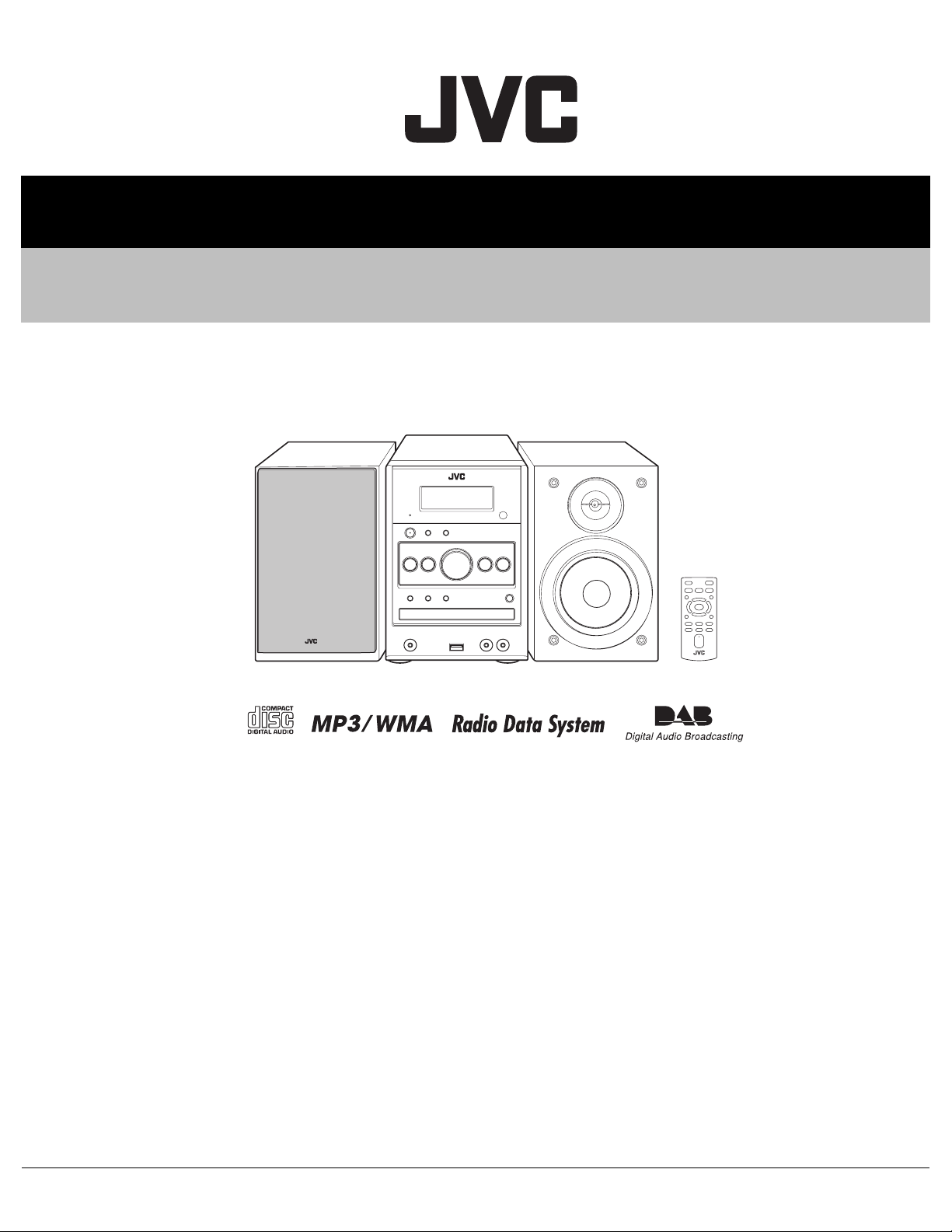
UX-DAB11B, UX-DAB11EN
MICRO COMPONENT SYSTEM
CA-UXDAB11 SP-UXDAB11SP-UXDAB11
COPYRIGHT © 2007 Victor Company of Japan, Limited
Lead free solder used in the board (material : Sn-Ag-Cu, melting point : 219 Centigrade)
Lead free solder used in the board (material : Sn-Cu, melting point : 230 Centigrade)
TABLE OF CONTENTS
1 PRECAUTION. . . . . . . . . . . . . . . . . . . . . . . . . . . . . . . . . . . . . . . . . . . . . . . . . . . . . . . . . . . . . . . . . . . . . . . . . 1-3
2 SPECIFIC SERVICE INSTRUCTIONS . . . . . . . . . . . . . . . . . . . . . . . . . . . . . . . . . . . . . . . . . . . . . . . . . . . . . . 1-7
3 DISASSEMBLY . . . . . . . . . . . . . . . . . . . . . . . . . . . . . . . . . . . . . . . . . . . . . . . . . . . . . . . . . . . . . . . . . . . . . . . 1-7
4 ADJUSTMENT . . . . . . . . . . . . . . . . . . . . . . . . . . . . . . . . . . . . . . . . . . . . . . . . . . . . . . . . . . . . . . . . . . . . . . . 1-19
5 TROUBLESHOOTING . . . . . . . . . . . . . . . . . . . . . . . . . . . . . . . . . . . . . . . . . . . . . . . . . . . . . . . . . . . . . . . . . 1-20
COPYRIGHT © 2007 Victor Company of Japan, Limited
No.MB633
2007/8
Page 2
SPECIFICATION
Amplifier section OUTPUT POWER 40 W (20 W + 20 W) at 6 Ω (10% THD)
Speakers/Impedance 6 Ω - 16 Ω
Audio input LINE IN 500 mV/47 kΩ (at “IN_LVL1”)
250 mV/47 kΩ (at “IN_LVL2”)
125 mV/47 kΩ (at “IN_LVL3”)
Audio output LINE OUT 1.0 Vrms (47 kΩ) (at “OUT_LVL1”)
2.0 Vrms (47 kΩ) (at “OUT_LVL2”)
Digital input USB MEMORY
Tuner section FM Tuning range 87.50 MHz - 108.00 MHz
AM (MW) Tuning range 522 kHz - 1 629 kHz
DAB tuning range BAND III 174.928 MHz - 239.200 MHz
L-BAND 1 452.960 MHz - 1 490.624 MHz
CD player section Dynamic range 88 dB
Signal-to-noise ratio 85 dB
Wow and flutter Immeasurable
USB storage USB specification Compatible with USB 2.0 Full Speed
Compatible device Mass storage class
Compatible file system FAT16, FAT32
Bus power supply Max. 500 mA
Speakers Speaker units Tweeter 1.5 cm dome x 1
Woofer 10 cm cone x 1
Impedance 6 Ω
Dimensions (approx.) 145 mm x 251 mm x 175 mm (W x H x D)
Mass (approx.) 1.7 kg each
General Power requirements AC 230 V , 50 Hz
Power supply to USB mass storage class device 5 V/500 mA
Power consumption 22 W (Power on)
2.3 W (On standby)
1.0 W or less (Save Mode)
Dimensions (approx.) 175 mm x 251 mm x 247 mm (W x H x D)
Mass 2.6 kg
Specifications and appearance are subject to change without prior notice.
1-2 (No.MB633)
Page 3

SECTION 1
PRECAUTION
1.1 Safety Precautions
(1) This design of this product contains special hardware and
many circuits and components specially for safety purposes. For continued protection, no changes should be made
to the original design unless authorized in writing by the
manufacturer. Replacement parts must be identical to
those used in the original circuits. Services should be performed by qualified personnel only.
(2) Alterations of the design or circuitry of the product should
not be made. Any design alterations of the product should
not be made. Any design alterations or additions will void
the manufacturers warranty and will further relieve the
manufacture of responsibility for personal injury or property
damage resulting therefrom.
(3) Many electrical and mechanical parts in the products have
special safety-related characteristics. These characteristics are often not evident from visual inspection nor can the
protection afforded by them necessarily be obtained by using replacement components rated for higher voltage, wattage, etc. Replacement parts which have these special
safety characteristics are identified in the Parts List of Service Manual. Electrical components having such features
are identified by shading on the schematics and by ( ) on
the Parts List in the Service Manual. The use of a substitute
replacement which does not have the same safety characteristics as the recommended replacement parts shown in
the Parts List of Service Manual may create shock, fire, or
other hazards.
(4) The leads in the products are routed and dressed with ties,
clamps, tubings, barriers and the like to be separated from
live parts, high temperature parts, moving parts and/or
sharp edges for the prevention of electric shock and fire
hazard. When service is required, the original lead routing
and dress should be observed, and it should be confirmed
that they have been returned to normal, after reassembling.
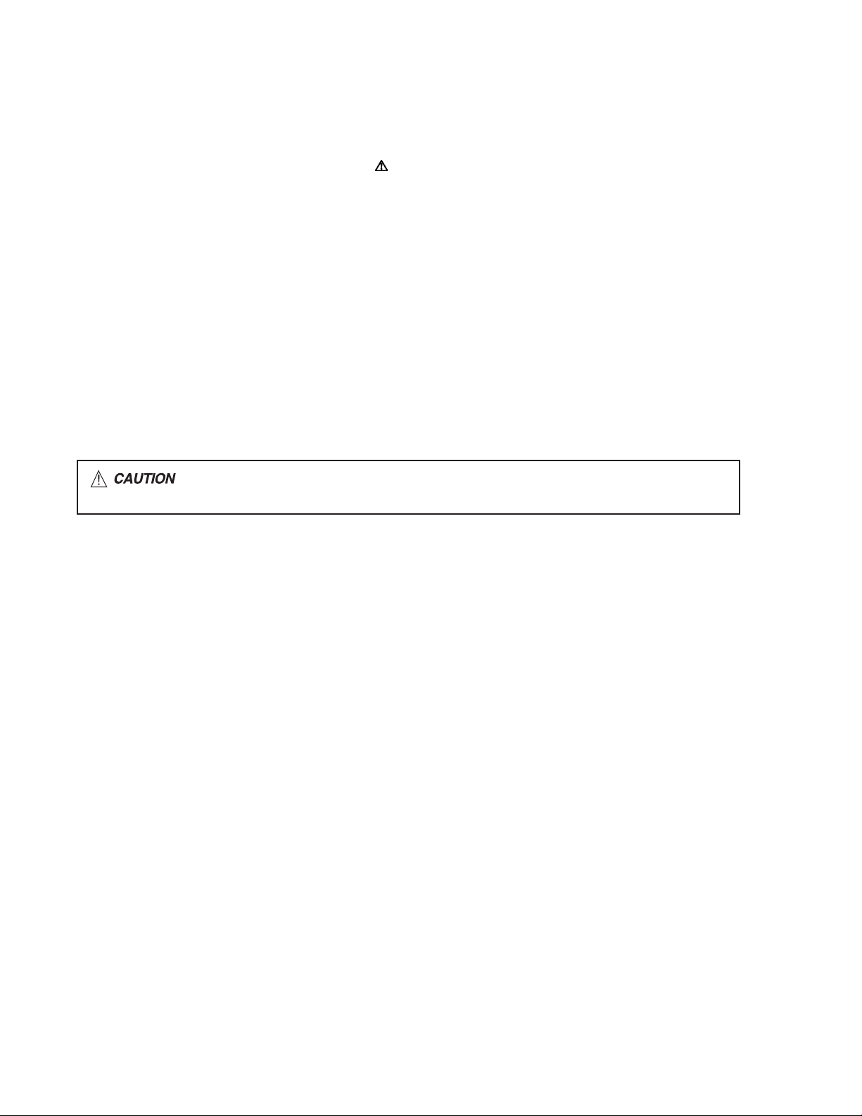
(5) Leakage shock hazard testing
After reassembling the product, always perform an isolation check on the exposed metal parts of the product (antenna terminals, knobs, metal cabinet, screw heads,
headphone jack, control shafts, etc.) to be sure the product
is safe to operate without danger of electrical shock.Do not
use a line isolation transformer during this check.
• Plug the AC line cord directly into the AC outlet. Using a
"Leakage Current Tester", measure the leakage current
from each exposed metal parts of the cabinet, particularly any exposed metal part having a return path to the
chassis, to a known good earth ground. Any leakage current must not exceed 0.5mA AC (r.m.s.).
• Alternate check method
Plug the AC line cord directly into the AC outlet. Use an
AC voltmeter having, 1,000Ω per volt or more sensitivity
in the following manner. Connect a 1,500Ω 10W resistor
paralleled by a 0.15µF AC-type capacitor between an ex-
posed metal part and a known good earth ground.
Measure the AC voltage across the resistor with the AC
voltmeter.
Move the resistor connection to each exposed metal
part, particularly any exposed metal part having a return
path to the chassis, and measure the AC voltage across
the resistor. Now, reverse the plug in the AC outlet and
repeat each measurement. Voltage measured any must
not exceed 0.75 V AC (r.m.s.). This corresponds to 0.5
mA AC (r.m.s.).
AC VOLTMETER
(Having 1000
ohms/volts,
or more sensitivity)
0.15 F AC TYPE
Place this
probe on
1500 10W
Good earth ground
1.2 Warning
(1) This equipment has been designed and manufactured to
meet international safety standards.
(2) It is the legal responsibility of the repairer to ensure that
these safety standards are maintained.
(3) Repairs must be made in accordance with the relevant
safety standards.
(4) It is essential that safety critical components are replaced
by approved parts.
(5) If mains voltage selector is provided, check setting for local
voltage.
1.3 Caution
Burrs formed during molding may be left over on some parts
of the chassis.
Therefore, pay attention to such burrs in the case of preforming repair of this system.
1.4 Critical parts for safety
In regard with component parts appearing on the silk-screen
printed side (parts side) of the PWB diagrams, the parts that are
printed over with black such as the resistor ( ), diode ( )
and ICP ( ) or identified by the " " mark nearby are critical
for safety. When replacing them, be sure to use the parts of the
same type and rating as specified by the manufacturer.
(This regulation dose not Except the J and C version)
each exposed
metal part.
(No.MB633)1-3
Page 4
1.5 Safety Precautions (U.K only)
(1) This design of this product contains special hardware and many circuits and components specially for safety purposes. For con-
tinued protection, no changes should be made to the original design unless authorized in writing by the manufacturer. Replacement parts must be identical to those used in the original circuits.
(2) Any unauthorised design alterations or additions will void the manufacturer's guarantee; furthermore the manufacturer cannot
accept responsibility for personal injury or property damage resulting therefrom.
(3) Essential safety critical components are identified by ( ) on the Parts List and by shading on the schematics, and must never
be replaced by parts other than those listed in the manual. Please note however that many electrical and mechanical parts in
the product have special safety related characteristics. These characteristics are often not evident from visual inspection. Parts
other than specified by the manufacturer may not have the same safety characteristics as the recommended replacement parts
shown in the Parts List of the Service Manual and may create shock, fire, or other hazards.
(4) The leads in the products are routed and dressed with ties, clamps, tubings, barriers and the like to be separated from live parts,
high temperature parts, moving parts and/or sharp edges for the prevention of electric shock and fire hazard. When service is
required, the original lead routing and dress should be observed, and it should be confirmed that they have been returned to
normal, after re-assembling.
1.5.1 Warning
(1) Service should be performed by qualified personnel only.
(2) This equipment has been designed and manufactured to meet international safety standards.
(3) It is the legal responsibility of the repairer to ensure that these safety standards are maintained.
(4) Repairs must be made in accordance with the relevant safety standards.
(5) It is essential that safety critical components are replaced by approved parts.
(6) If mains voltage selector is provided, check setting for local voltage.
Burrs formed during molding may be left over on some parts of the chassis. Therefore,
pay attention to such burrs in the case of preforming repair of this system.
1-4 (No.MB633)
Page 5
1.6 Preventing static electricity
Electrostatic discharge (ESD), which occurs when static electricity stored in the body, fabric, etc. is discharged, can destroy the laser
diode in the traverse unit (optical pickup). Take care to prevent this when performing repairs.
1.6.1 Grounding to prevent damage by static electricity
Static electricity in the work area can destroy the optical pickup (laser diode) in devices such as laser products.
Be careful to use proper grounding in the area where repairs are being performed.
(1) Ground the workbench
Ground the workbench by laying conductive material (such as a conductive sheet) or an iron plate over it before placing the
traverse unit (optical pickup) on it.
(2) Ground yourself
Use an anti-static wrist strap to release any static electricity built up in your body.
(caption)
Anti-static wrist strap
1M
Conductive material
(conductive sheet) or iron palate
(3) Handling the optical pickup
• In order to maintain quality during transport and before installation, both sides of the laser diode on the replacement optical
pickup are shorted. After replacement, return the shorted parts to their original condition.
(Refer to the text.)
• Do not use a tester to check the condition of the laser diode in the optical pickup. The tester's internal power source can easily
destroy the laser diode.
1.7 Handling the traverse unit (optical pickup)
(1) Do not subject the traverse unit (optical pickup) to strong shocks, as it is a sensitive, complex unit.
(2) Cut off the shorted part of the flexible cable using nippers, etc. after replacing the optical pickup. For specific details, refer to the
replacement procedure in the text. Remove the anti-static pin when replacing the traverse unit. Be careful not to take too long a
time when attaching it to the connector.
(3) Handle the flexible cable carefully as it may break when subjected to strong force.
(4) I t is not possible to adjust the semi-fixed resistor that adjusts the laser power. Do not turn it.
1.8 Attention when traverse unit is decomposed
*Please refer to "Disassembly method" in the text for the pickup unit.
• Apply solder to the short land sections before the card wire is disconnected from the connecto on the servo board. (If the card wire
is disconnected without applying solder, the pickup may be destroyed by static electricity.)
• In the assembly, be sure to remove solder from the short land sections after connecting the card wire.
Short land part
p
Pickup Connector Card wire
(No.MB633)1-5
Page 6
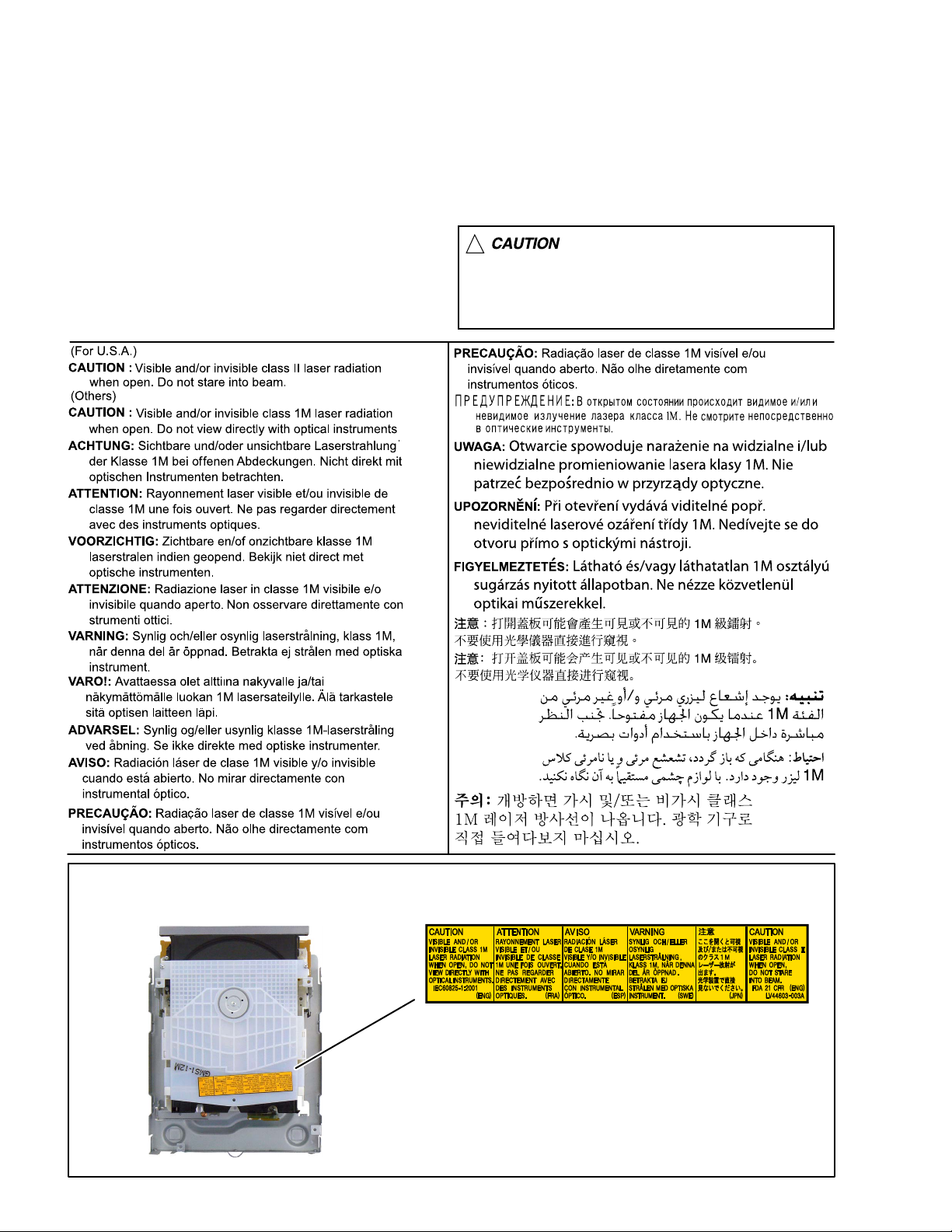
1.9 Important for laser products
1.CLASS 1 LASER PRODUCT
2.CAUTION :
(For U.S.A.) Visible and/or invisible class II laser radiation
when open. Do not stare into beam.
(Others) Visible and/or invisible class 1M laser radiation
when open. Do not view directly with optical instruments.
3.CAUTION : Visible and/or invisible laser radiation when
open and inter lock failed or defeated. Avoid direct
exposure to beam.
4.CAUTION : This laser product uses visible and/or invisible
laser radiation and is equipped with safety switches which
prevent emission of radiation when the drawer is open and
the safety interlocks have failed or are defeated. It is
dangerous to defeat the safety switches.
5.CAUTION : If safety switches malfunction, the laser is able
to function.
6.CAUTION : Use of controls, adjustments or performance of
procedures other than those specified here in may result in
hazardous radiation exposure.
!
Please use enough caution not to
see the beam directly or touch it
in case of an adjustment or operation
check.
REPRODUCTION AND POSITION OF LABELS and PRINT
WARNING LABEL and PRINT
1-6 (No.MB633)
Page 7
SECTION 2
SPECIFIC SERVICE INSTRUCTIONS
This service manual does not describe SPECIFIC SERVICE INSTRUCTIONS.
SECTION 3
DISASSEMBLY
3.1 Main body
3.1.1 Removing the METAL COVER (See Fig.1, 2)
(1) Remove the six screws A attaching the METAL COVER.
(See Fig.1)
(2) Remove the two screws B attaching the both side of MET-
AL COVER. (See Fig.2)
AA
Fig.1
B
Fig.2
(No.MB633)1-7
Page 8
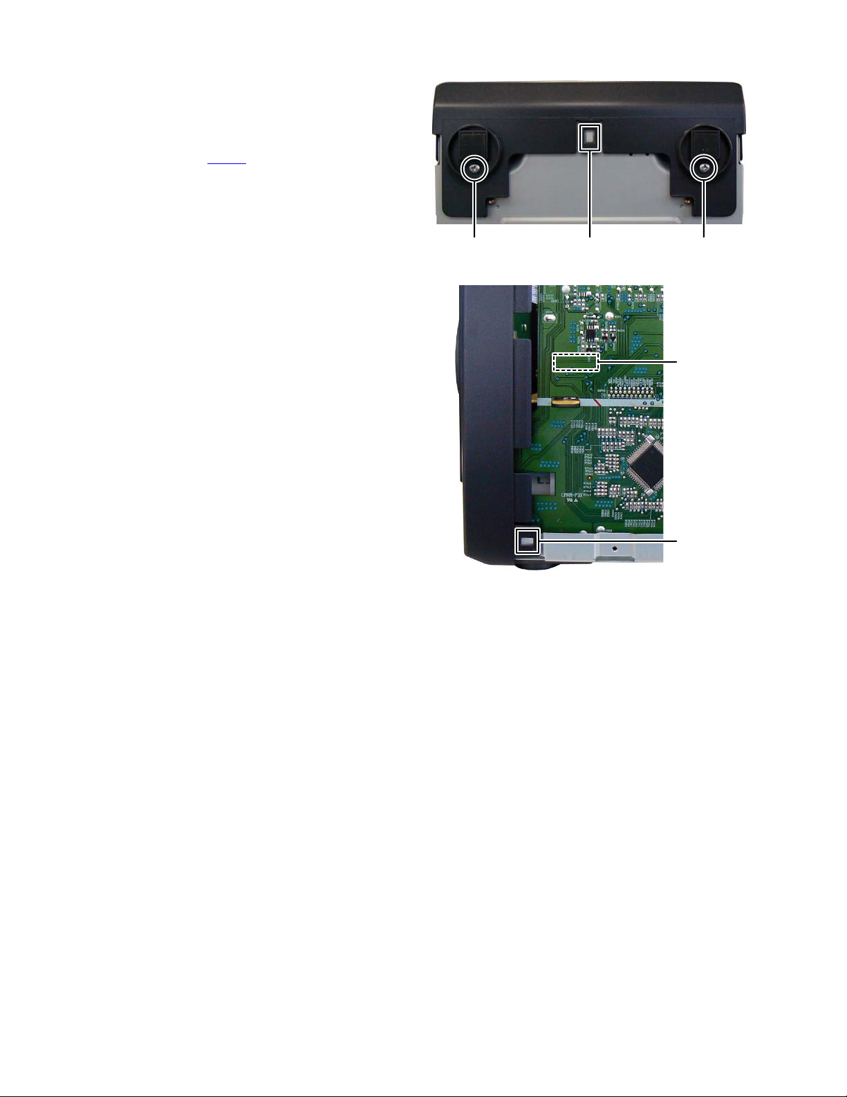
3.1.2 Removing the FRONT PANEL assembly (See Fig.3, 4)
(1) Remove the two screws C attaching the FRONT PANEL
assembly. (See Fig.3)
(2) Disengage one hook a of the bottom side and two hooks b
of both side of the FRONT PANEL assembly. (See Fig.3, 4)
(3) Disconnect the card wire from FRONT BOARD assembly
connected to connector CN432
sembly. (See Fig.4)
of the MAIN BOARD as-
CC
hook a
Fig.3
Fig.4
CN432
hook
b
1-8 (No.MB633)
Page 9
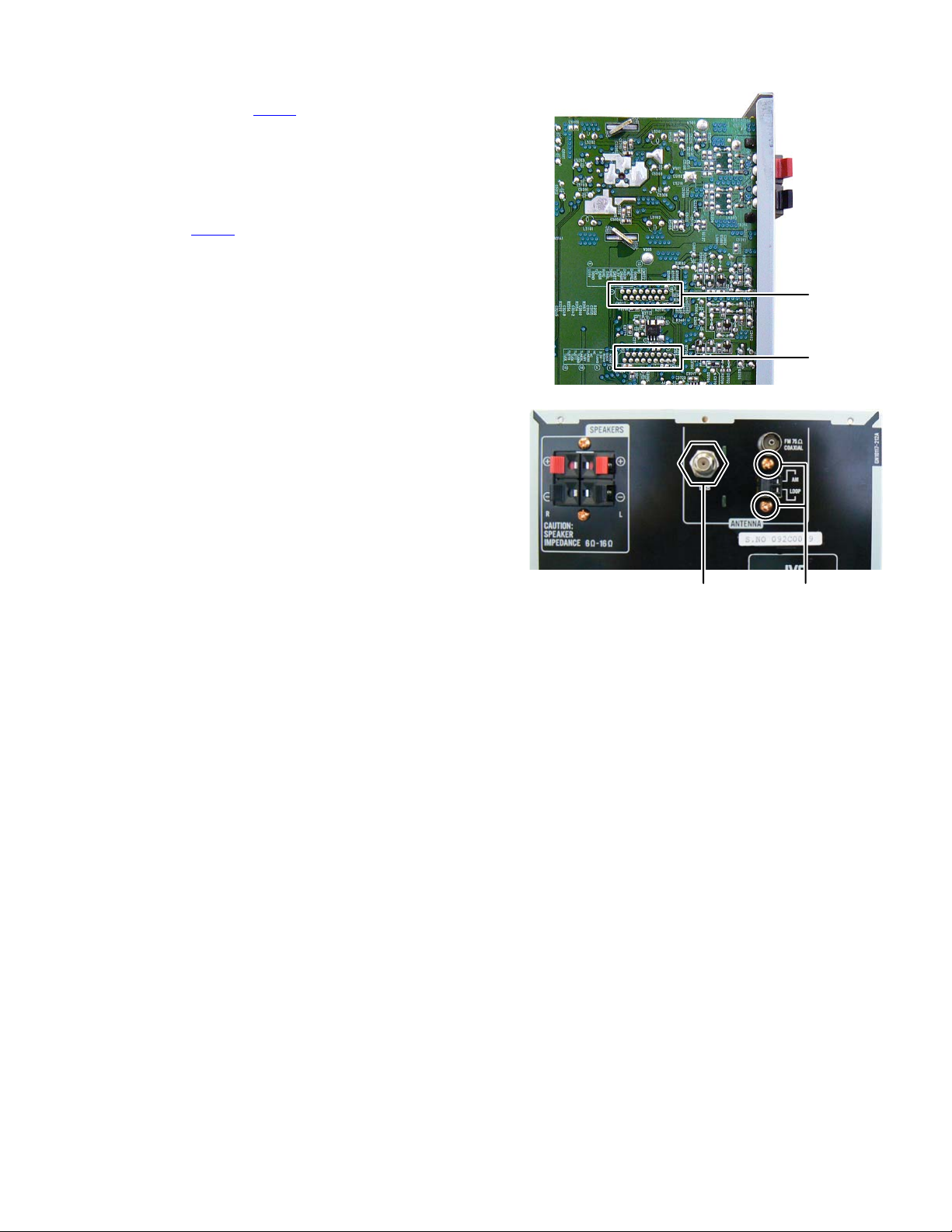
3.1.3 Removing the DAB TUNER PACK (See Fig.5, 6)
(1) Disconnect the card wire from DAB TUNER PACK con-
nected to connector CN372
bly. (See Fig.5)
(2) Remove the one nut D attaching the DAB TUNER PACK.
(See Fig.6)
3.1.4 Removing the TUNER PACK (See Fig.5, 6)
(1) Disconnect the card wire from TUNER PACK connected to
connector CN911
Fig.5)
(2) Remove the two screws E attaching the TUNER PACK.
(See Fig.6)
of the MAIN BOARD assembly. (See
of the MAIN BOARD assem-
CN372
CN911
Fig.5
DE
Fig.6
(No.MB633)1-9
Page 10
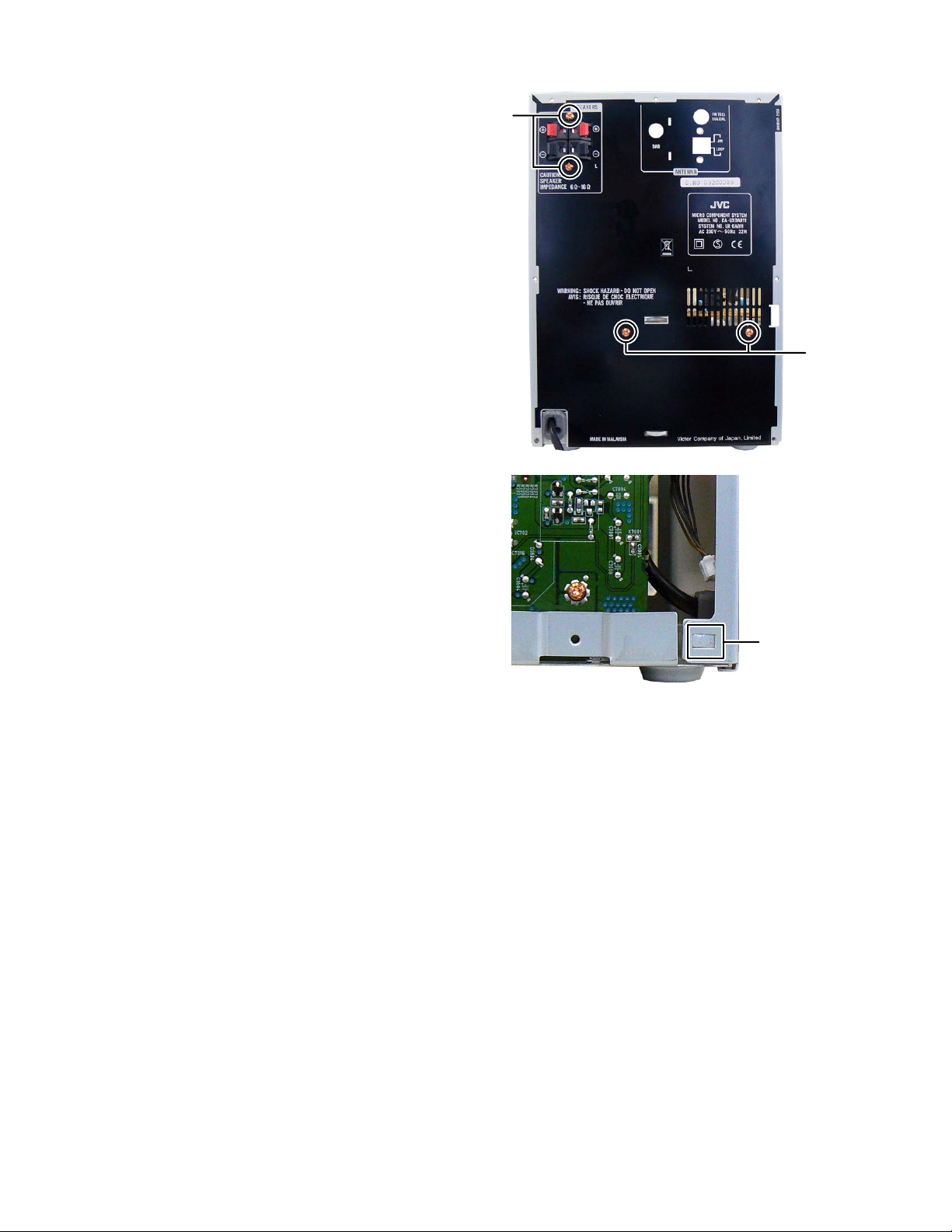
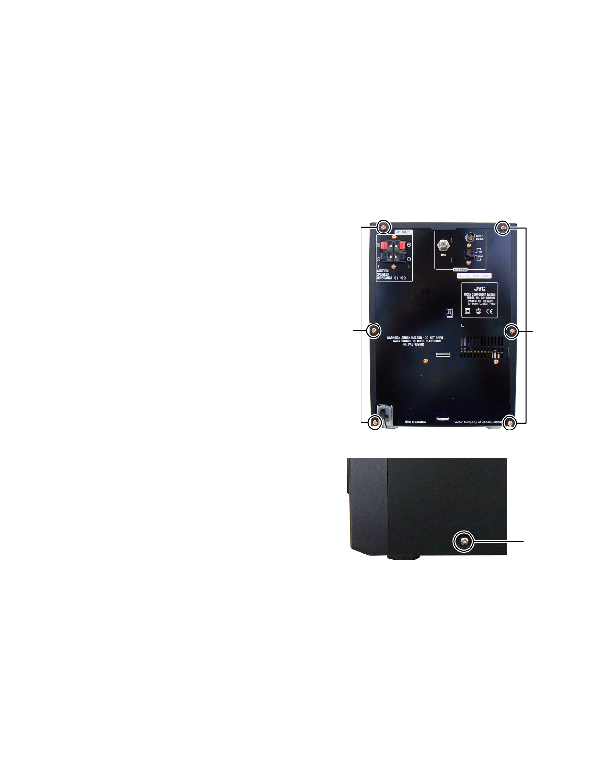
3.1.5 Removing the REAR PANEL (See Fig.7, 8)
(1) Remove the two screws F attaching the SPEAKER TERMI-
NAL. (See Fig.7)
(2) Remove the two screws G attaching the POWER BOARD
assembly. (See Fig.7)
(3) Disengage two hooks c engaged both side of REAR PAN-
EL. (See Fig.8)
F
G
Fig.7
Fig.8
hook
c
1-10 (No.MB633)
Page 11

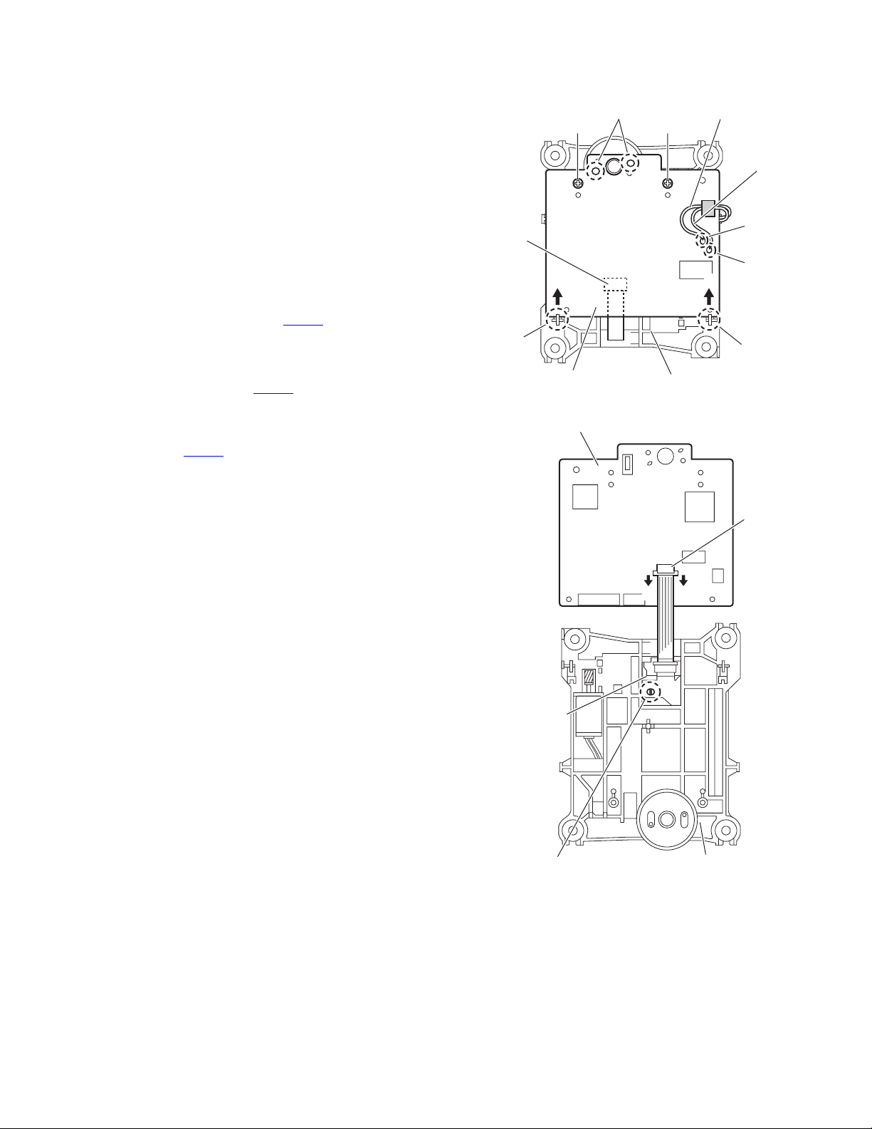
3.1.6 Removing the MAIN BOARD assembly (See Fig.9, 10)
(1) Remove the one screw H attaching the earth wire. (See
Fig.9)
(2) Remove the one screw J attaching the MAIN BOARD as-
sembly. (See Fig.10)
(3) Disconnect the connectors CN373
BOARD assembly connected the POWER BOARD assembly. (See Fig.10)
(4) Disconnect the connector CN401
sembly connected the JACK BOARD assembly. (See
Fig.10)
(5) Disconnect the connector wire from CD MECHANISM as-
sembly connected to connector CN708
BOARD assembly. (See Fig.10)
and CN709 of the MAIN
of the MAIN BOARD as-
of the MAIN
H
Fig.9
CN709 CN373
3.1.7 Removing the POWER BOARD assembly (See Fig.11)
(1) Disconnect the power cord connected to connector P901
the POWER BOARD assembly.
(2) Disconnect the card wire from CD MECHANISM assembly
connected to connector CN701
sembly.
(3) Remove the one screw K attaching the POWER BOARD
assembly.
(4) Slide to the arrow and then lift up the POWER BOARD as-
sembly.
of the POWER BOARD as-
of
CN708CN401
Fig.10
Fig.11
J
CN701
K
P901
(No.MB633)1-11
Page 12
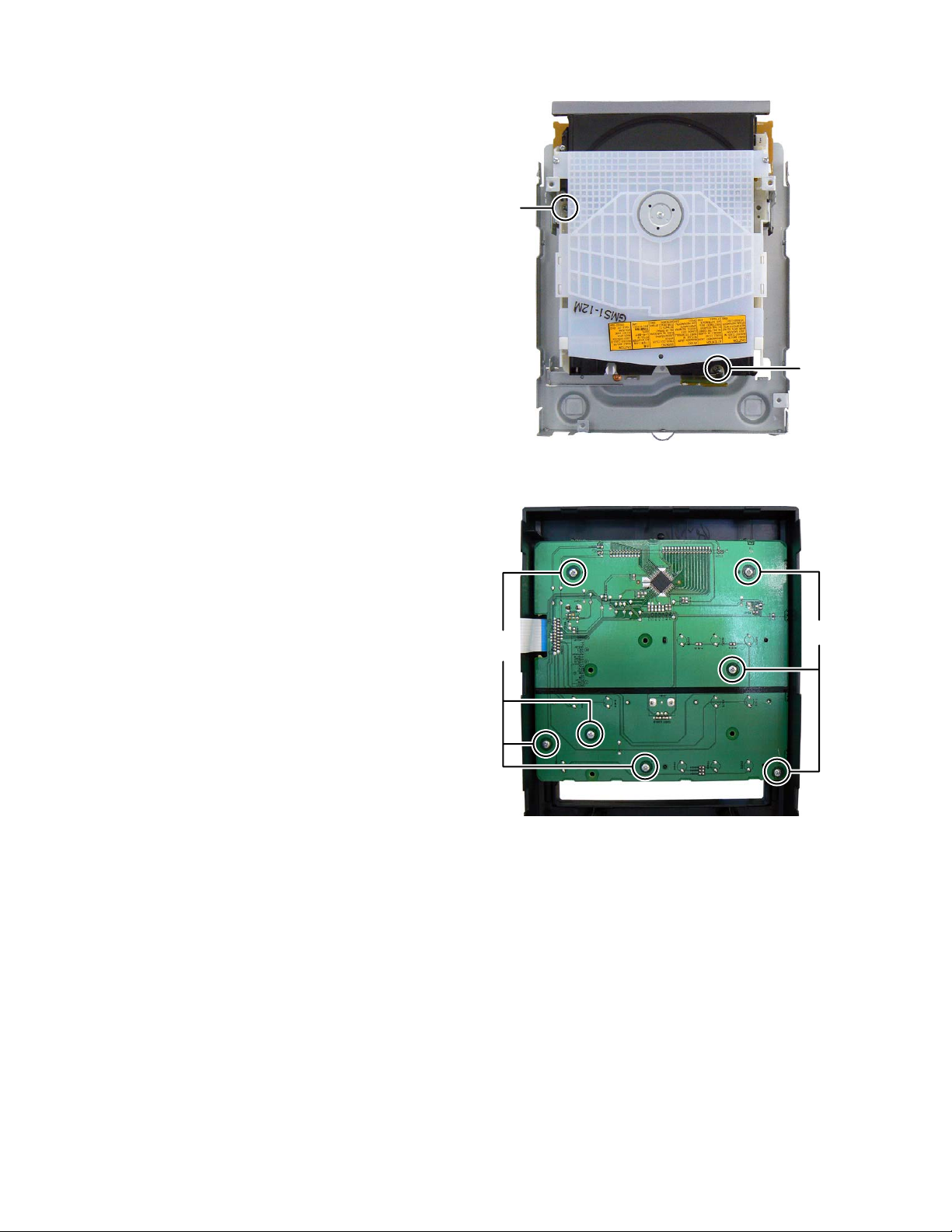
3.1.8 Removing the CD MECHANISM assembly (See Fig.12)
(1) Remove the two screws L attaching the CD MECHANISM
assembly.
3.1.9 Removing the FRONT BOARD assembly (See Fig.13)
(1) Remove the volume knob.
(2) Remove the seven screws M attaching the FRONT
BOARD assembly.
L
L
Fig.12
M
M
Fig.13
1-12 (No.MB633)
Page 13
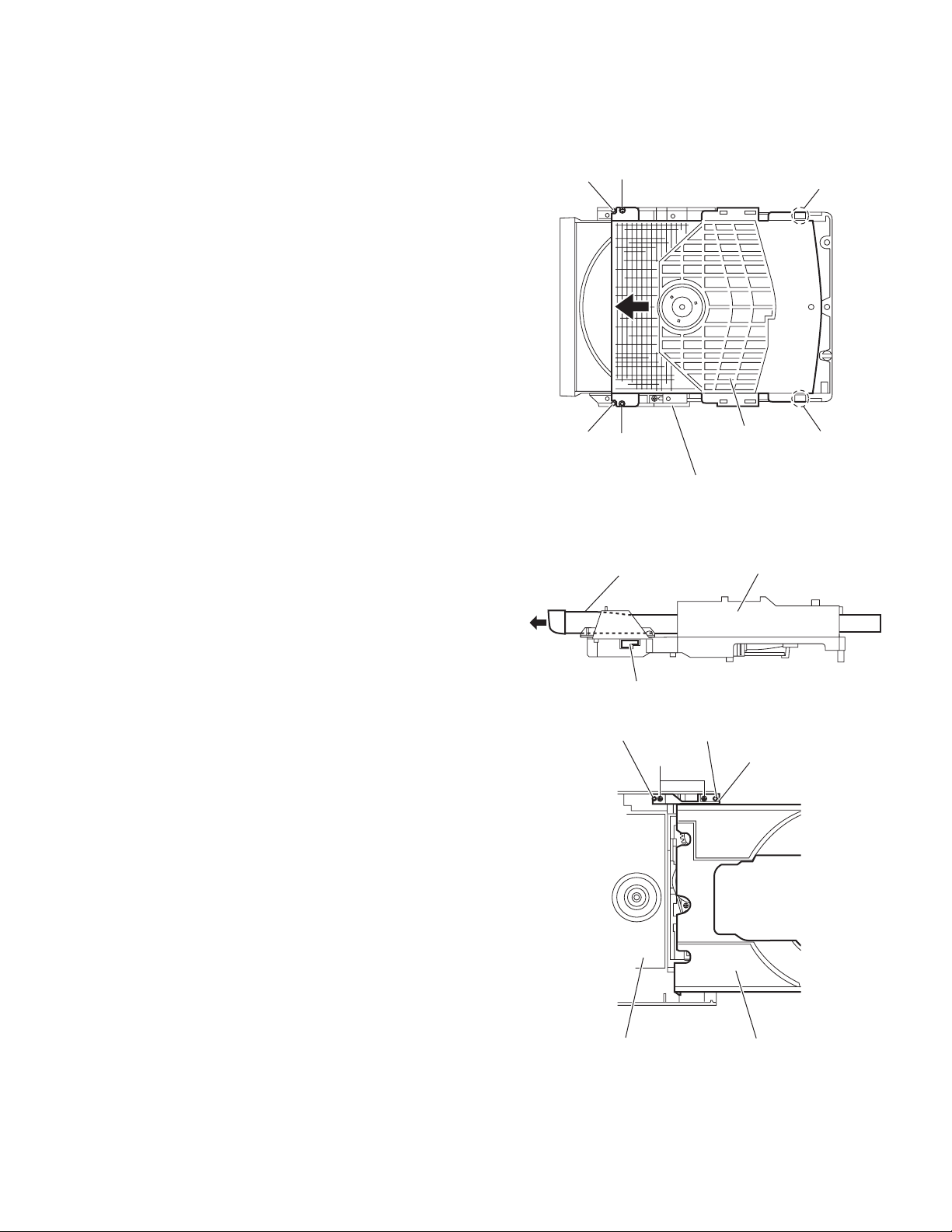
3.2 CD mechanism assembly
• Remove the CD mechanism assembly from main body.
3.2.1 Removing the CD cover
(See Fig.1)
(1) Remove the two screws A attaching the CD cover from bot-
tom side of CD mechanism assembly.
(2) Lift up the CD cover from disengage boss a of the CD
mechanism assembly.
(3) Slide the CD cover to direction of the arrow and remove the
CD cover from fixing part of b.
(4) Remove the CD cover.
Boss a
A
Fixing part b
3.2.2 Removing the tray assembly
(See Fig.2 and 3)
• Remove the CD cover.
(1) Press slide cam and pull out the tray assembly to direction
of the arrow from right side of CD mechanism assembly.
(See Fig.2)
(2) Remove the two screws B attaching the tray assembly
from upper side of CD mechanism. (See Fig.3)
(3) Remove the bussing of the tray assembly from boss c of
the CD mechanism assembly and remove the tray assembly. (See Fig.3)
Fig.1
Fig.2
Boss
CD cover
c
Bussing
Boss a
A
CD mechanism assembly
Tray assembly CD mechanism assembly
Slide cam
Boss c
B
Fixing part b
Fig.3
Tray assemblyCD mechanism assembly
(No.MB633)1-13
Page 14
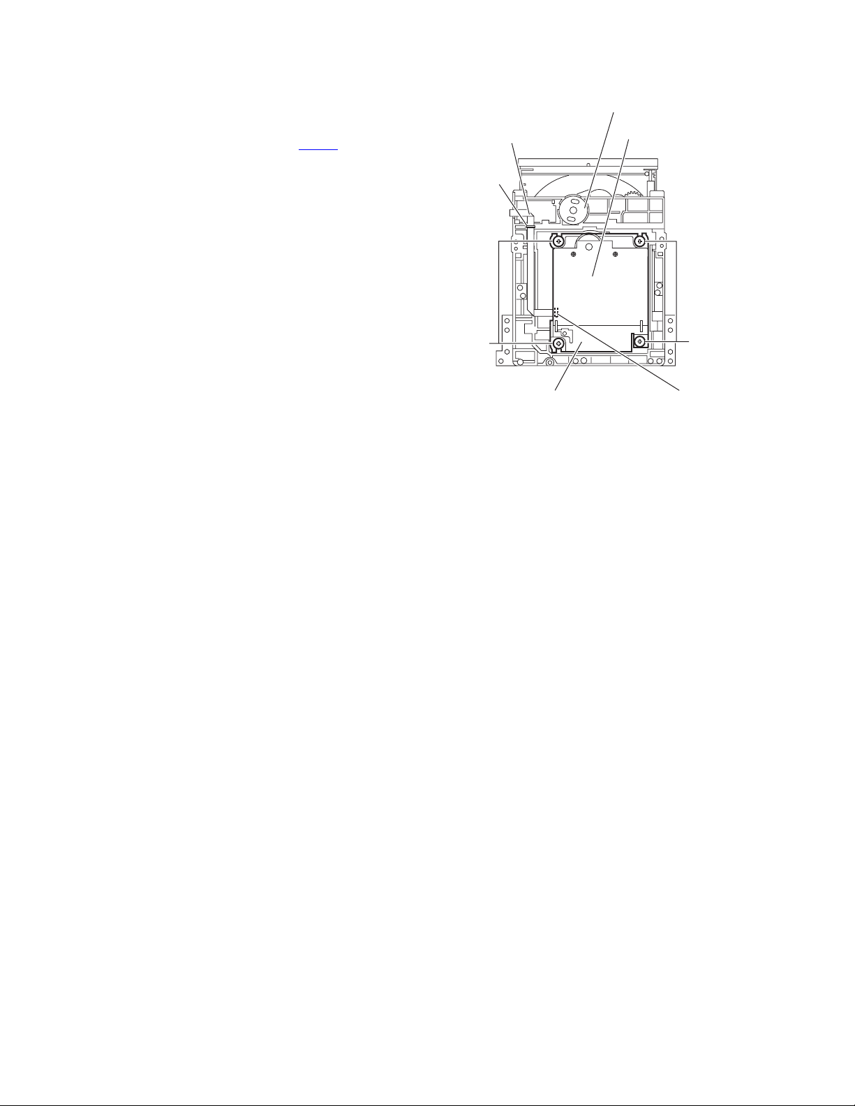
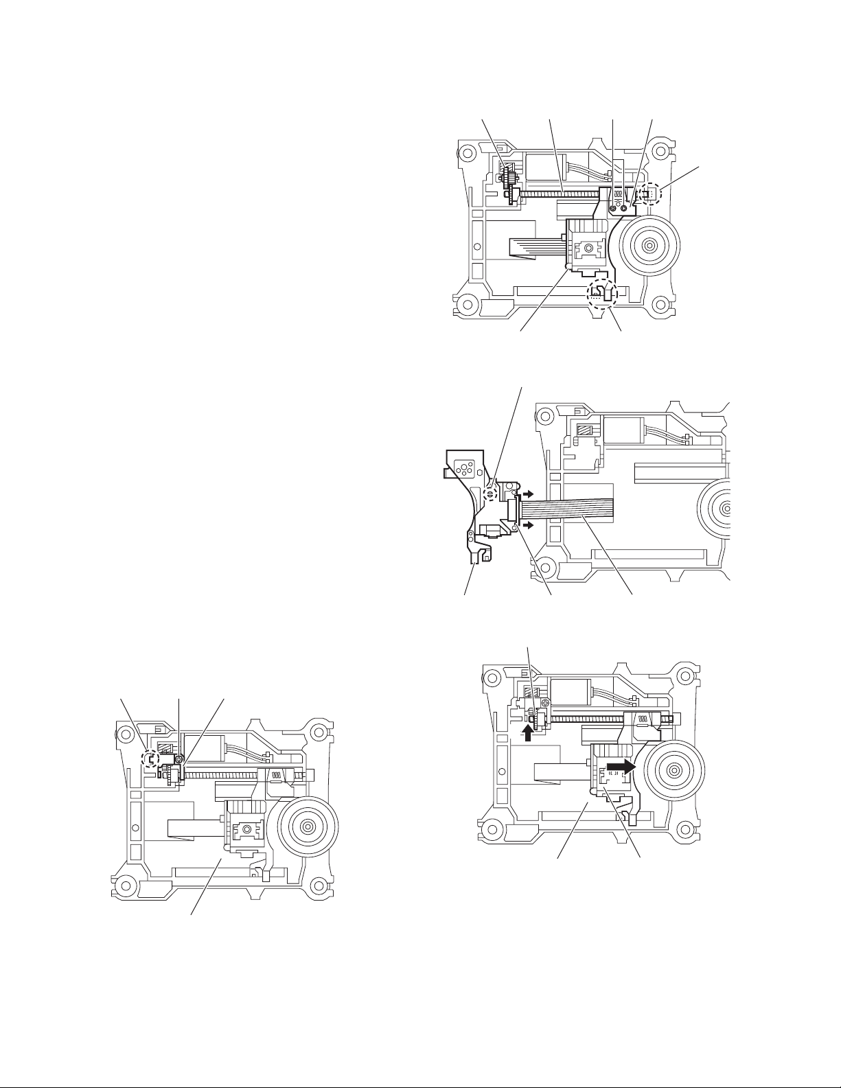
3.2.3 Removing the traverse mechanism assembly
(See Fig.4)
(1) Remove the four screws C attaching the traverse mecha-
nism assembly from bottom side of CD mechanism assembly.
(2) Disconnect the card wire from connector CN602
servo board and then take out the traverse mechanism assembly and CD servo board together.
Reference:
When reattaching the traverse mechanism assembly, the card
wire should through the part d.
of the CD
Card wire
d
CD mechanism assembly
CD servo board
C
Traverse mechanism assembly
Fig.4
C
CN602
1-14 (No.MB633)
Page 15
3.2.4 Removing the CD servo board
(See Fig.5 and 6)
• Remove the traverse mechanism assembly.
(1) Remove the two screws D attaching the CD servo board
from bottom side of traverse mechanism assembly. (See
Fig.5)
(2) Remove the solder from solder part e of the CD servo
board. (See Fig.5)
(3) Remove the yellow wire from solder part f of the CD servo
board. (See Fig.5)
(4) Remove the white wire from solder part h of the CD servo
board. (See Fig.5)
(5) Remove the CD servo board to upper side, disengage the
hook c to direction of the arrow 1 then turn over the CD ser-
vo board. (See Fig.5)
(6) Solder to short land part j of pickup. (See Fig.6)
(7) Release the lock of connector CN601
row 2 and disengage the card wire. (See Fig.6)
Caution:
• Solder to short land part j of the pickup then disconnect the
card wire from connector CN601
disconnect the card wire before soldering, pickup is make
sure destroyed by static electricity. (See Fig.6)
• When reattaching the CD servo board, connect the card wire
to connector CN601
land part j of the pickup.
and then remove the solder of short
to direction of the ar-
of the CD servo board. If
CN601
Hook h
Solder part e
Yellow wire
DD
White wire
Solder
part f
Solder
㧝㧝
Traverse mechanism assemblyCD servo board
Fig.5
CD servo board
part g
Hook h
Pickup
Short land part j
CN601
22
Traverse mechanism assembly
Fig.6
(No.MB633)1-15
Page 16
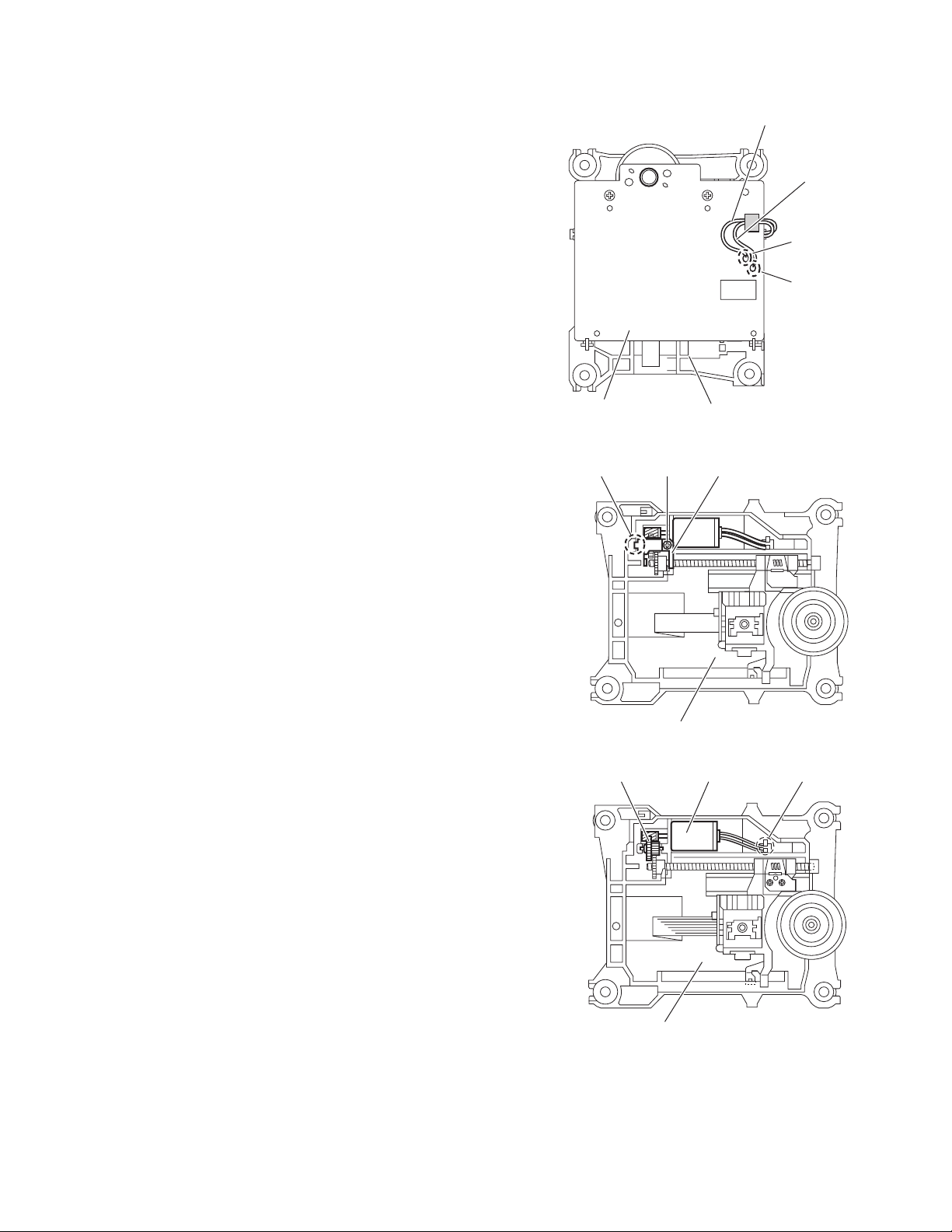
3.2.5 Removing the pickup
(See Fig.7 to 9)
• Remove the traverse mechanism assembly.
(1) Remove the one screw E attaching the plate from upper
side of traverse mechanism assembly. (See Fig.7)
(2) Remove the plate from fixing part k then take out the plate.
(See Fig.7)
(3) Remove the two screws F attaching the LEAD spring and
then take out the LEAD spring. (See Fig.8)
(4) Take out the feed gear, and then remove the shaft of pick-
up from part m of the traverse mechanism assembly. (See
Fig.8)
(5) Remove the pickup from part n of the traverse mechanism
assembly and then take out pickup with shaft. (See Fig.8)
(6) Release the shaft from pickup. (See Fig.8)
(7) Solder the short land part p of the pickup. (See Fig.9)
(8) Release the lock of the connector to direction of the arrow,
and then disconnect the card wire. (See Fig9)
Caution:
• Solder to short land part p of the pickup then disconnect the
card wire from connector. If disconnect the card wire before
soldering, pickup is make sure destroyed by static electricity.
(See Fig.9)
• When reattaching the pickup, connect the card wire to con-
nector and then remove the solder from short land part p.
(See Fig.9)
Feed gear Shaft LEAD spring
Pickup
Short land part p
F
Part m
Fig.8
Part m
3.2.6 Attaching the pickup
(See Fig.7 to 10)
• Please refer the "Removing the pickup".
(1) Connect the card wire to connector of pickup, and then re-
move the solder from short land part p of the pickup. (See
Fig.9)
(2) Attach the shaft to pickup. (See Fig.8)
(3) Fit the pickup to part n of the traverse mechanism and then
attach the end of the shaft to part k. (See Fig.8)
(4) Attach the LEAD spring and feed gear. (See Fig.8)
(5) Attach the plate. (See Fig. 7)
(6) One turn the LEAD gear to direction of the arrow 1 and fully
shift to direction of the arrow 2. (See Fig.10)
Plate
Fixing part k
E
Pickup Connector Card wire
Fig.9
LEAD gear
1
2
Traverse mechanism assembly
Fig.10
Pickup
1-16 (No.MB633)
Traverse mechanism assembly
Fig.7
Page 17
3.2.7 Removing the feed motor
(See Fig.11 to 13)
• Remove the traverse mechanism.
(1) Remove the yellow wire from solder part q of the CD servo
board from upper side of traverse mechanism. (See Fig.11)
(2) Remove the white wire from solder part r of the CD servo
board. (See Fig.11)
(3) Remove the one screw G attaching the plate. (See Fig.12)
(4) Disengage the plate from fixing part s and take out the
plate. (See Fig.12)
(5) Remove the feed gear and take out the feed motor. (See
Fig13)
Reference:
When attaching the feed motor, the wire has to through the
part t of the traverse mechanism assembly. (See Fig.13)
Fixing part s
G
Yellow wire
White wire
Soldered part q
Soldered part r
Traverse mechanism assemblyCD servo board
Fig.11
Plate
Traverse mechanism assembly
Fig.12
Feed gear Feed motor
Traverse mechanism assembly
Fig.13
part t
(No.MB633)1-17
Page 18

3.2.8 Removing the switch board
(See Fig.14)
(1) Disconnect the card wire from CN1
from bottom side of CD mechanism assembly.
(2) Remove the wire from solder part u of the switch board.
(3) Remove the one screw H attaching the switch board to CD
mechanism assembly.
(4) Lift up the switch board by pushing the hook v of CD mech-
anism assembly and take out it from part w.
Reference:
• After attach the switch board to CD mechanism assembly,
wire hooked to part x.
•Hook u of the CD mechanism assembly, it have to bond
lock.
3.2.9 Removing the motor
(See Fig.14 and 15)
• Remove the tray assembly.
(1) Remove the wire from solder part u of the switch board
from bottom side of CD mechanism assembly.
(2) Remove the belt of motor pulley from upper side of CD
mechanism assembly. (See Fig.15)
Caution:
Belt should not apply grease.
(3) Remove the two screws J attaching the motor to CD mech-
anism assembly and take out the motor from bottom side
of CD mechanism assembly. (See Fig.15)
Reference:
After motor attached to CD mechanism assembly, wire should
hook to part w. (See Fog.14)
of the switch board
Switch board Wire
Solder
part u
CN1
Part w
H
CD mechanism assembly
J
Hook v
Part w
Fig.14
CD mechanism assembly
Belt
Fig.15
Motor pulley
1-18 (No.MB633)
Page 19

SECTION 4
ADJUSTMENT
4.1 TEST MODE
(1) In DAB mode, Press "SET" key + "BASS/TRE" key + "POWER" key to enter test mode.
(2) FL display indicate SYSTEM MICON version "53095 00".
(3) Wait 5 sec., FL indicate the DAB MICON version "V017-00".
After this, internal information of DAB MICON indicate to FL sequence to presss "DISPLAY" key.
System Micon version
53095 00
DAB Micon version
V017-00
TUN SET3
SID
Audio err
EIC err
EID
RF SET
BUTTON INDICATION FUNCTION
[POWER]
+
[SET]
+
[REPEAT]
[POWER]
+
[SET]
+
[FM MODE/PLAY MODE]
COLD
V_E_RDS
TUN SET2
TUN SET1
NOW SEQ
DAB MODE
COLD START
(Initialization of set)
Version indication
[POWER]
+
[SET]
+
[S.TURBO]
[POWER]
+
[SET]
+
[FADE MUTING]
[POWER]
+
[SET]
+
[BASS/TREBLE]
[POWER]
+
[SET]
+
[SLEEP]
(FL ALL DISPLAY)
VOL MAX
V_E_RDS MG38_256 1129B FF R,1.29.00
(CLOCK FAST FORWARD)
FL all display
Volume level to max by compulsion.
Micon version indication
Whenever the button is pushed, the
display replaces it.
Clock minute fast increase by 1 every
seconds.
(No.MB633)1-19
Page 20

SECTION 5
TROUBLESHOOTING
This service manual does not describe TROUBLESHOOTING.
1-20 (No.MB633)
Page 21

(No.MB633)1-21
Page 22

Victor company of Japan, Limited
Audio/Video Systems category 10-1,1chome,Ohwatari-machi,Maebashi-city,371-8543,Japan
(No.MB633)
Printed in Japan
VPT
Page 23

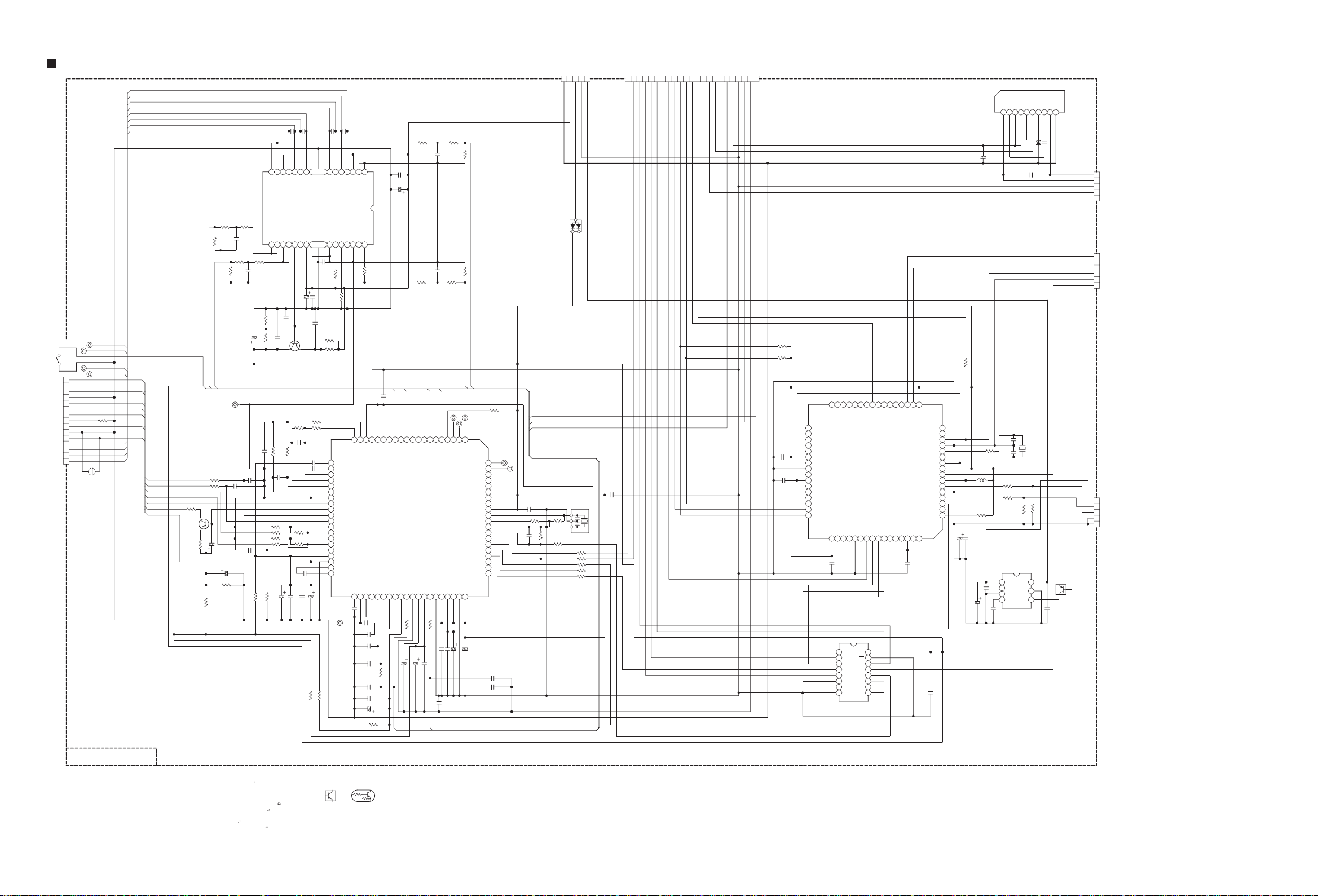
SCHEMATIC DIAGRAMS
MICRO COMPONENT SYSTEM
UX-DAB11B,UX-DAB11EN
CD-ROM No.SML200708
Lead free solder used in the board (material : Sn-Ag-Cu, melting point : 219 Centigrade)
Lead free solder used in the board (material : Sn-Cu, melting point : 230 Centigrade)
Contents
Block diagrams
Standard schematic diagrams
Printed circuit boards
COPYRIGHT 2007 Victor Company of Japan, Limited.
CA-UXDAB11 SP-UXDAB11SP-UXDAB11
2-1
2-2
2-8 to 11
No.MB633SCH
2007/8
Page 24

In regard with component parts appearing on the silk-screen printed side (parts side) of the PWB diagrams, the
parts that are printed over with black such as the resistor ( ), diode ( ) and ICP ( ) or identified by the " "
mark nearby are critical for safety.
Page 25

Block diagram
LCD & Key switch section
D2411
STANDBY
DI221
LCD DISPLAY
LED
LED1
IC221
LCD DRIVER
KEY0, KEY1
S2501 to S2507
S2509 to S2512
LINEIN, FM/AM
USB, CD
KEY MATRIX
VOL1
JS261
VOL2
VOLUME
IC241
REMOCON
REMOCON
LINE/HP/USB Jack section
LINE
IN
LINE
LINE IN AMP.
LINEOUTL/R
OUT
HPOUTL/R
J8001J4352J4351
HEADPHONE
HPDET
CN103
USB
SP+/-
CD traverse
mechanism
TRV+/-
FO+/-
CN202
TR+/-
CD pickup
mechanism
S201
REST SW
S1
TRAY SWITCH
LOADING
MOTOR
M
Loader section
PULSW
LDSWOP
LDSWCL
CN721
CN1
LM+/-
CD servo control section
GR1 to 10
SG1 to 16
IC401
CN104
CN101
USBD+/-
IC101
USB
CONTROLER
BTL. AMP.
IC721
LOADER
System control & Audio Amp section
F+/-
VFDCLK
VFDSTB
VFDDIN
VFDDOUT
-VDISP
CN221
LINEINL/R
CN402
LINEINL/R
LINEOUTL/R
CN401
HPOUTL/R
HPDET
VFDCLK
VFDSTB
VFDDIN
VFDDOUT
KEY0, KEY1
LINEIN, FM/AM
USB, CD
VOL1, VOL2
CN432
REMOCON
-VDISP
Q3701
Q3702
F+/-
FVFD
VFD SW
F+/-
D+/-
USB5V
USBNPP
USBCS, USBREQ, USBSDA, USBSCL, USBRST, USBIN
CDMCCLK, CDMDATA
CDMLD, CD_NRST
12MHz
IC601
LDOPEN
LDCLOSE
IC102,Q101
USB 5V REG.
X101
TRVP, SPOUT
TRP, FOP
A+C, B+D, E, F
LD, PD
IC605
CD/USB
SELECT SW
CDSTAT
IC602
EEPROM
US6V
MCLK, MDATA
MLD, NRST
DSP
IC801
Q8102,Q8103
Q8301
HP AMP./MUTE
HPMUTE
E2CLK
E2DATA
IC702
USB4V
US6V
CD8V
USBSEL
CDCLK, CDDATA
CDLD, CDRST
CDIRQ
CDL/R
X601
16.93MHz
X7001
8MHz
Q4601
Q4603
LINEOUT
MUTE
Q7002
BUP
CN201
CN203
Q4501 to Q4503
Q4604
Q4606
LINE
VOLUME
LMUTE LOUTLEVEL
IC701
MICON
BUPMOD
RESETIN
Q7001
RESET
FUSB
USB4V
IC373
USB4V
CN708 CN701
REG.
US6V
Q3501
CD8V
Q3502
CD8V
Primary & Regulator section
IC452
QP LINK
FCD
SAFETY2
REG.
16.5V
FQPL
QPLINK
LSEL0
RSEL0
LOUT
ROUT
VOLCE
VOLCK
VOLDT
USBCS
USBREQ
USBSDA
USBSCL
USBRST
USBIN
USBSEL
CDCLK
CDDATA
CDLD
CDRST
CDSTAT
CDIRQ
PULSW
LDSWOP
LDSWCL
CN709
CN702
L5
R5
IC303
E.VOLUME
CDL/R
CDL/R
DABL/R
FDABANT
LDOPEN
LDCLOSE
F+/-
D953
LOPOUT
ROPOUT
TUNERL/R
FSW9V
CN373
CN901
D951
SW9V
Q3401,Q3402
SW9V REG.
16.5V
US4V
IC372
US4V REG.
US6V
FDAB(DABON)
IC374
DAB5V REG.
US6V
Q3705,Q3706
DAB12V REG.
16.5V
US6V
IC903
US6V REG.
-VDISP
DABRX
DABTX
DABRESET
US5V
12V
D954
Q3601,Q3602
AHB
AHBPRO
SAFETY1
DABL/R
CN141
CN372
DAB Module section
SW REG.
16.5V
CONTROL
POWER
TRANS.
LINP
RINP
FTU
X1
24.576MHz
IC51
DAB
DAC
US5V
IC901
T901
POWER AMP.
Q3801,Q3802
TU9V REG.
SMCK
SCLK
SDAT1
SLRCK
DZF
DACCSN
DACCCLK
DACCDT
DACRST
DABRX
DABTX
DABRESET
3.3V
IC71
3.3V REG.
D901
DIODE
BRIDGE
L+/-
IC501
POUT
SMUTE
SAFETY3
R+/-
TUCE
TUCK
TUDTI
TUDTO
RDSCK
RDSDT
RDSON
TU9V
16.5V
TU91,Q81,Q82
DAB TUNER
IF_OUTTP
IF_OUTTN
IC1
DAB BASE BAND
MP2 DECODER
WFIC, NIRQ
MPUDAI
MPUDAO
MPUEN, MPUCK
MPUMOD
CONTROLLER
DABON
X101
16MHz
J5001
TO
SPEAKER
CN911
DABRST
IC101
EEPRMCS
EEPRMCK
EEPRMDO
EEPRMDI
IC191
EEPROM
P901
AC IN
TUNER
UNIT
ANT+BIN
TUSCL
TUSDA
PDET
2-1
Page 26
Standard schematic diagrams
Primary & Regulator section
F901
AC
21
P901
QGA7901C1-02
! QMFZ059-2R0-E
T2.0AH/250V
FC902
FC901
QNG0019-001Z
QNG0019-001Z
GNA10051-A1
!
!
*
!
C905
R901
3.3M
R902
C903
!
0.15/AC275V
100P/AC250V
!
L901
QQR1800-001
!
!
1
C902
23
C904
!
0.068/AC275V
!
0.001/AC250V
C901
IC901
MIP4190MDSLJ
HS901
GN40147-001A
0.001/AC250V
!
4
C906
100P/AC250V
!
2431
(297.3V)
(5.8V)
(16V)
(0.6V)
(1.6V)
D901
KBJ4J
CN901
D955
MTZJ6.8B-T2
QGB2510K2-10
F+
-20V
-23V
-27V
0V
0V
6.2V
16V
9.3V
0V
0V
-VDISP
16.5V
LDCLOSE
LDOPEN
1
F-
2
3
GND
4
TO CN373
GND
5
6V
6
7
SW9V
8
9
10
LDOPEN
LDCLOSE
LDCLOSE
SW9V
L902
QQR1800-001
!
1
C919
4
23
C911
330P/2000
7
D
6
NC
C912
0.1/16
5
VDD
4
S
(0V)
3
VCC
2
TR
1
FB
C913
C914
12P/50
MA2SD32-X
D905
3.3K
R908
R909
4.3K
C916
330P/50
0.0047/2000
0.1/50
C915
2.2/50
0.0047/2000
!
C909
C907
!
100
C908
330P/2000
!
R903
22K
2W
!
D902
SF27-B351C
D903
!
SF27-B351C
1
3
5
56K
R905
C920
0.0022/50V
!
68K
R904
6
C910
47/50
NI
R911
!
D904
R910
1SS244-T2
10
C917
0.1/16
!
C918
0.001/AC250V
!
!
TL431/A/-T
T901
QQS0404-001
PC901
PC123Y82FZ
32
5.1V
3
IC902
2
!
D954
MBR10150CT
7
NI
C963
8
!
D951
10
1F4G-G-T2
680/25
680/25
C961
C957
C951
39/50
!
R959
10
FR
1/4W
11
C955
470/10
!
!
12
R951
14
7.5K
1.5k
R952
R954
C960
1k
1
2.4V
1
R956
1F4G-G-T2
NI
CP901
D953
QMFZ050-1R5X-E
R953
11K
2K
R955
QQLZ037-220
L954
22
C958
680/25
C962
D950
NI
220/25
IC903
PQ1CG21H2FZ
VIN2VOUT3GND4Oadj5CTRL
(16V)
1
QQL50AK-221Z
L952
220
C953
220/25
1000/10 C954
EC30HA04-X D952
(0V)
(6.6V)
(1.2V)
(6.4V)
!
CP902
ICP-N20-T
CP
3.9K
R957
1K
R958
0.1/16 C956
LDOPEN
CN701
QGF1040F1-23
0V
CDIRQ
1
CDSTAT
2
3
4
5
6
7
8
9
10
11
12
TO CN203
13
14
15
16
17
18
19
20
21
22
23
SW9V
0V
CDRST
3.5V
CDDATA
3.5V
CDCLK
3.5V
CDLD
3.5V
USBSEL
0V
USBCS
0V
0.2V
USBREQ
0.3V
USBSDA
USBSCL
0.3V
USBIN
0.9V
USBRST
0V
LDSWCL
0V
LOSWOP
0V
LDOPEN
0V
LDCLOSE
3.5V
PULSW
9.3V
SW9V
0V
DGND
0V
CDL
1.6V
AGND
0V
CDR
1.6V
NOTES
VOLTAGES ARE DC-MEASURED WITH A DIGITAL
1.
2.
3.NI MEANS NO INSERT
OR OSCILLOSCOPE WITHOUT INPUT SIGNAL.
VOLT METER
CONDITION ---
UNLESS OTHERWISE SPECIFIED.
ALL RESISTORS ARE CARBON FILM RESISTOR
ALL CAPACITORS ARE
MYLAR CAPACITOR.
ALL RESISTANCE VALUES ARE
ALL CAPACITANCE VALUES ARE IN F(P=pF).
ALL CAPACITORS ARE SHOWN IN THE FORM
OF
ALL INDUCTANCE VALUES ARE IN H(m=mH).
CAPACITANCE( F)
CD STOP MODE
1/4W
CERAMIC CAPACITOR
/RATED VOLTAGE (V).
Parts are safety assurance parts.
5%
IN OHM( ).
OR
QGB1214K1-20S
CN702
CDIRQ
CDSTAT
CDRST
CDDATA
CDCLK
USBSEL
USBCS
USBREQ
USBSDA
USBSCL
USBIN
USBRST
LDSWCL
LDSWOP
PULSW
1
2
3
4
5
CDLD
6
7
8
TO CN709
9
10
11
12
13
14
15
16
DGND
17
AGND
18
CDL
19
CDR
20
When replacing those parts make
sure to use the specified one.
2-2
Page 27

Micon section
TO POWER & AUDIO SECTION
TO CN221
DGND
-VDISP
F+
F-
US3.3V
FOR FLASH
12345
EMULATOR
ONLY ES&PP STEP
MP NO USE
BACKUPMUTE
VOL1
VOL2
VOLDT
VOLCE
VOLCK
RDSCK
RDSDT
RDSON
SAFETY1
SAFETY2
KEY0
KEY1
QGF1016C6-20W
CN432
LINEIN
3.5V
1
FM/AM
3.5V
2
USB
3.5V
3
CD
3.5V
4
GND
0V
5
KEY0
3.5V
6
KEY1
3.5V
7
POUT
3.5V
8
VFDDOUT
3.5V
9
VFDDIN
3.5V
10
VFDCLK
3.5V
11
VFDSTB
3.5V
12
REMOCON
3.5V
13
VOL1
3.5V
14
VOL2
3.5V
15
US3.3V
3.5V
16
-23.6V
F-
17
-21.1V
F+
18
-VDISP
-26.2V
19
0V
DGND
20
VFDDOUT
VFDDIN
VFDCLK
VFDSTB
REMOCON
KEY0
KEY1
VOL1
VOL2
SAFETY3
POUT
USB
FM/AM
CD
LINEIN
GNA10052
VCC
GND
3.5V0V3.5V
REST
CE
DATA
0.3V0V0.3V
6
CN706
NI
CLK
VFDSTB
VFDCLK
VFDDIN
VFDDOUT
C7016
0.047/16
3.5V 0V0V0V
8
BR24L04F-W-X
0V
FVFD
POUT
FQPL
C7013
0.1/16
1K
1KR7061
1K
1K
R70601KR7059
R7062
FQPL
0V
0V
0V
0V
0V
0V
0V
0V
0.1/16
C7015
FQPL
R7063
72
73
74
75
FVFD
VFDDIN
VFDSTB
VFDCLK
76 VOL1
77 VOL2
78 NC
79 VOLDT
80 VOLCE
81 VOLCK
82 E2DATA
83 NC
84 E2CLK
85 RDSCK
86 RDSDT
87 RDSON
88 CDIRQ
89 VDDS
90 NC
91 VSS
92 SAFETY1
93 SAFETY2
94 SAFETY3
95 KEY0
96 KEY1
97 VERSION
98 MODEL
99 NC
100
SAFETY2
LOUTLEVEL
LOUTLEVEL
SAFETY2
VFDDOUT
(3.3V)
(3.3V)
(3.5V)
(3.5V)
(3.5V)
ADPOWER
(0.7V)
(0V)
S2DTX2D2SRX3FDAB4USBSDA5USBIN6USBSCL7USBREQ8LDOPEN9LDCLOSE10LDSWOP11NMOD12OSC213OSC114VSS15NC16NC17VDD18VDD1819RESETIN20LOSWCL21USBCS22USBSEL23USBRST24FUSB25FSW9V
1
0V0V0V0V0V
0V
0V
1K
1K
1K
2.2K
10K
R7007
R7099
DABTX
DABRX
FCD
HPMUTE
FCD
HPMUTE
2.2K
2.2K
R70101KR7011
R7012
R7013
R7009
R7008NIR7006
FDAB
LDOPEN
USBIN
USBREQ
USBSDA
USBSCL
1
W313
1
W304
1
W306
C9003
FVFD
FUSB
HPDET
FDABANT
FVFD
FUSB
HPDET
FDABANT
R7092
NI
10K
10K
R7301
R7302
3.3K
R7085
R7086
NI
7WP6
5
SCL
SDA
VCC
IC702
GND3A22A11A0
4
RDSON
RDSON
RDSCK
RDSCK
RDSDT
RDSDT
Q7003
NI
B5001
10
L7004
TUCE
TUCK
TUDTI
TUDTO
TUCE
TUCK
TUDTI
TUDTO
1K
100K
1K
100K
100K
R7088
R7087
R7080
R7081
R7082
CDIRQ
FTU
VOLDT
VOLCK
VOLCE
FSW9V
AHBPRO
SAFETY1
VOLDT
VOLCK
VOLCE
FSW9V
AHBPRO
SAFETY1
3.5V
R7304
2.2K
R7303
3.5V
2.2K
R7064
3.5V
100
100
R7065
100
R7066
3.5V
R7067
2.2K
R7068
2.2K
R7069
2.2K
R7070
2.2K
R7071
2.2K
1K
R7072
3.5V
C7014
0.1/16
R7073
2.2K
2.1V
2.2K
R7074
2.1V
R7075
2.2K
2.2K
R7076
3.5V
2.2K
R7077
3.5V
0.9V
3.5V
3.5V
10K
10K
4.7
L7003
R7084
R7083
POUT
LMUTE
SMUTE
QPLINK
SAFETY3
FTU
POUT
LMUTE
SMUTE
QPLINK
SAFETY3
FDAB
2.2K
R7014
LDCLOSE
NI
FDAB
66NC67NC68NC69NC70NC71
0V
LDSWOP
DABTX
DABTX
10K
10K
R7053
R7054
0V
0V
64
65
BUPCTL
IC701
MN101E16ZXW
MN101E16KXW
(0V)
4.7K
R7100
X7001
QAX0902-004
R7097
AGND
DABRX
DABREST
DABRX
DABREST
BUPMOD
(1.7V)
10K
0.01/50
1K
1K
R7052
R7051
3.3V
3.3V
61
62
63
VSS
FQPL
POUT
(1.7V)
0V
0V
C7009
22P/50
C7010
22P/50
R7098
C9001
SMUTE
1K
R7050
60
SMUTE
(FLASH ROM)
(MASK ROM)
10K
LMUTE
22K
R70491KR7048
59
LMUTE
(3.5V)
1/10
R7090
100/16C7006
USB4V
LOUTLEVEL
58
LOUTLEVEL
(1.8V)
C7018
0.1/16
10K
CDR
HPMUTE
2.2K
R7047
57
C7017
R7015
0.1/16
C7005
2.2K
R70461KR7045
0.3V0V3.3V0V3.3V
HPDET
HPMUTE
(3.5V)
0V0V0V
1K
LDSWCL
K7001
NQR0389-003X
C3511
CDL
CD8V
HPDET
55NC56
0V
1K
R7016
USBCS
QPLINK
3.3V
53NC54
QPLINK
1KR7018
1KR7017
USBSEL
USBRST
L7001
10
470/16
MGND
12345
0V
QGA2001C1-05
TO CN201
FTU
AHBPRO
330
1K
R7043
R7044
0V
3.5V
51
52
FTU
AHBPRO
(1.8V)
(3.5V)
(3.5V)
(0V)
(3.5V)
(3.5V)
3.5V
1KR7019
FUSB
CD8V
USB4V
6.5V
CN708
(0V)
R7021
3.5V
330R7020
FSW9V
NI
C7008
US6V
DGND
0V
4.0V
0V
R7042
50TUCE
3.5V
R7041
49TUCK
R7040
0V
48TUDTI
3.5V
47TUDTO
R7038
3.5V
46USB
3.5V
45AUX
R7036
3.5V
44TU
R7035
3.5V
43CD
R7034
3.5V
42FCD
R7033
3.5V
41PULSW
R7032
3.5V
40CDLD
0V
39VSS
R7031
3.5V
38CDRST
C7012
0.1/16
37VDD18
R7030
36CDCLK
R7029
35CDSTAT
R7028
34CDDATA
33NC
32NC
31NC
30NC
R7024
29FDABANT
R7023
28DABREST
27NC
R7022
26REMOCON
NI
MA111-X
0
100K
R7004
R7005
130
C7003
NI
NI
C7004
C7007
CDIRQ
CDRST
CDSTAT
CDDATA
123456789
0V0V0V0V0V0V0V
6.2V
TO POWER SECTION (TO CN702)
150P/50
D7004
1
0V
0V
CDCLK
D7003
NI
RT1N430C-X
CDLD
2.2K
2.2K
2.2K
2.2KR7039
2.2K
2.2KR7037
2.2K
2.2K
330
2.2K
0
2.2K
0
2.2K
0
1K
1K
2.2K
R7091
3
-
2
1.8V
Q7002
USBCS
USBSEL
0V
TUCE
TUCK
TUDTI
TUDTO
FCD
PULSW
CDLD
CDRST
CDCLK
CDSTAT
CDDATA
FDABANT
DABREST
REMOCON
10K
10K
R7089
TP799
3.5V
D7002
NI
MTZJ3.3B-T2
C7002
R7002
10K
USBIN
PULSW
USBSCL
USBRST
USBSDA
LDSWCL
USBREQ
QGB1214J1-20S
LDSWOP
1011121314151617181920
0V0V0V0V0V
CN709
Q7001
RT1N430C-X
0V
R7001
10K
DGND
R7093
10K
10K
R7094
R7095
10K
10K
R7096
C7001
10/50
0V
D7001
1SS133-T2
NOTES
1.
VOLTAGES ARE DC-MEASURED WITH A DIGITAL
VOLT METER
OR OSCILLOSCOPE WITHOUT INPUT SIGNAL.
CD STOP MODE
CONDITION ---
2.
UNLESS OTHERWISE SPECIFIED.
LDOPEN
LDCLOSE
CDR
CDL
AGND
0V0V0V0V0V0V0V
MGND
AGND
DGND
US6V
US4V
LDOPEN
LDCLOSE
TO POWER & AUDIO SECTION
ALL RESISTORS ARE CARBON FILM RESISTOR
ALL CAPACITORS ARE
MYLAR CAPACITOR.
ALL RESISTANCE VALUES ARE
ALL CAPACITANCE VALUES ARE IN F(P=pF).
ALL CAPACITORS ARE SHOWN IN THE FORM
CAPACITANCE( F)
OF
ALL INDUCTANCE VALUES ARE IN H(m=mH).
3.NI MEANS NO INSERT.
4.DIGITAL TRANSISTOR
=
RT1N430C-X
KRC110S-X
4.7K
5%
1/4W
CERAMIC CAPACITOR
/RATED VOLTAGE (V).
OR
IN OHM( ).
TO POWER & AUDIO SECTION
2-3
Page 28

Front panel & Headphone section
GNA10051-A2
STOP
12
S2504
QSW0825-001Z
S2509
QSW0825-001Z
LINE
S2510
12
QSW0825-001Z
DA/BFM/AM
S2511
12
QSW0825-001Z
USB
S2512
12
QSW0825-001Z
CD
12
TUPRB
12
S2507
QSW0825-001Z
DIMMER
12
S2506
QSW0825-001Z
12
S2505
QSW0825-001Z
QSW1130-001
JS261
R2505
R2504
132
C2601
0.01
510
430
C2602
QSW0825-001Z
QSW0825-001Z
QSW0825-001Z
FWD SKIP
12
S2503
BWD SKIP
12
S2502
OPEN/CLOSESTB
12
S2501
0.01
FM/AM
LINE
123456789
3.5V
3.5V
USB
3.5V
GNA10051-A3
C4302
47/25
R4301
47K
47/25
C4301
47K
R4302
C4303
2.2/50
R4305
1K
C4307
C4308
NI
NI
100K
R4303
100K
R4304
J4351
QNS0188-001
J4352
QNS0188-001
J8001
QNS0188-001
CN103
QNZ0926-001
0V
6
0V
2
L
0V
1
R
0V
3
0V
4
0V
7
G
0V
5
0V
6
0V
2
L
0V
1
R
0V
3
0V
4
0V
7
G
0V
5
0V
6
0V
2
L
0V
1
0V
R
3
0V
4
0V
7
G
0V
5
5V
D-
D+
GND
543216
C111
0.0018
CHS GND
R4251
13K
R4151
13K
K4351
0
NI
NI
220P
C4351
0
C4651
0
0.1
C8206
C8306
0V
0V
0V
0V
0V
15PC114
15PC115
C113
NI
C116
0
C4251
C4151
K4602
0
K8101
K8201
R8302
0
0.1
C8106
C4152
NQR0389-003X
NQR0389-003X
1K
NQR0389-003XK8301
C8305
1.5/6.3
C8351
0
CHS GND
NI
0.0018
C112
D103
C4304
2.2/50
51K
51K
220P
R4152
R4252
C4252
C4399
0
CHS GND
0.1/16
C8307
K103
K106
K105
2
3
D101
STZC6.8N-X
1
(U only:RT1P431C-X)
Q2411
NI
R2411
24
SLR-343VC/NPQ-T
D2411
1.2K
R2503
510
R2502
430
R2501
STANDBY
R2206
10K
IC241
NJL23H380A-E
OUT
123
3.5V
VCCGND
0V
3.5V
C2209
22/6.3
C2208
NI
R2207
0
C2201
NC
F+
32F+1
0.1
GR9
GR10
NI
R2203
100k
NI
NI
0.0047C2210
NI
C2202
R2204
R2205
GR5
GR7
GR6
GR4
GR2
GR8
0V
0V
0V
0V
1.9V
3.3V
3.4V
3.4V
3.4V
0V
0V
NIC2203
GR3
C2207
1
VSS
1234567891011
LED1
LED2
LED3
LED4
OSC
DOUT
DIN
CLK
STB
K1
K2
VSS
1213141516171819202122
0V
3.5V 3.5V
C2204
0.1
GR1
-23.4V
GR1
VDD
PT6315
VDD
SG1/KS1
-23.4V
SG1
DI221
QLF0190-001
SG3
36P235P334P433P532P631P730P829P928
37P139 40F-41
SG2
SG1
NC
F-
LINE IN
LINE OUT
HEADPHONE OUT
P1027P1126P1225P1324P1423P1522P16141G132G123G114G105G96G87G78G69G510G
GR1
SG16
SG15
SG14
SG13
SG12
SG11
SG10
SG9
SG8
SG7
SG6
SG5
SG4
GR9
GR8
GR7
GR6
GR5
GR4
GR3
GR2
-23.4V
-23.4V
-23.4V
-23.4V
-23.4V
-23.4V
-23.4V
-23.4V
3435363738394041424344
GR4
GR3
GR2
IC221
SG2/KS2
-23.4V
SG2
SG21/GR8
SG20/GR9
SG22/GR7
SG23/GR6
SG24/GR5
SG19/GR10
NC
NC
VEE
SG16/KS16
SG15/KS15
SG14/KS14
SG13/KS13
SG12/KD12
SG11/KS11
SG10/KS10
SG3/KS3
SG4/KS4
SG5/KS5
SG6/KS6
SG7/KS7
SG8/KS8
SG9/KS9
C2205
-23.4V
-23.4V
-23.4V
-23.4V
-23.4V
SG3
SG4
SG5
SG6
SG7
0.022
-23.4V
-23.4V
SG8
SG9
GR10
-23.4V
SG16
-23.4V
SG15
-23.4V
SG14
-23.4V
SG13
-23.4V
-23.4V
SG12
SG11
-23.4V
SG10
-23.4V
23 24 25 26 27 28 29 30 31 32 33
C2206
NI
USB IN
CN221
KEY0
CD
3.5V
GND
KEY1
POUT
3.5V
3.5V0V3.5V
VFDDIN
VFDSTB
VFDCLK
VFDDOUT
1011121314151617181920
3.5V
3.5V
3.5V
TO CN432
REMOCON
3.5V
F+
VOL2
-VDISP
VOL1
3.5V
3.5V
DGND
US3.3V
F-
QGF1040F1-20
3.5V
3.5V
-23.6V
-26.2V0V-21.2V
NOTES
VOLTAGES ARE DC-MEASURED WITH A DIGITAL
1.
2.
OR OSCILLOSCOPE WITHOUT INPUT SIGNAL.
VOLT METER
CD STOP MODE
CONDITION ---
UNLESS OTHERWISE SPECIFIED.
ALL RESISTORS ARE CARBON FILM RESISTOR
ALL CAPACITORS ARE
MYLAR CAPACITOR.
ALL RESISTANCE VALUES ARE
ALL CAPACITANCE VALUES ARE IN F(P=pF).
ALL CAPACITORS ARE SHOWN IN THE FORM
CAPACITANCE( F)
OF
ALL INDUCTANCE VALUES ARE IN H(m=mH).
5%
1/4W
CERAMIC CAPACITOR
/RATED VOLTAGE (V).
IN OHM( ).
3.NI MEANS NO INSERT
4.DIGITAL TRANSISTOR
4.7K
OR
RT1P431C-X
KRA101S-X
=
4.7K
0V
VEE
IC401
NJM4565M-WE
NQR0502-002XK102
NQR0502-002X
NQR0022-002X
NQR0022-002X
C4305
100P
3V3V
3V
1234
-
+
+
-
VCC
765
8
6.2V
3V3V
3V
C4306
100P
1K
R4306
NI
D102
LINEINL
1
3.1V
LINEINR
2
3.1V
AGND
3
0V
LINEOUTL
4
0V
LINEOUTR
5
0V
US6V
6.3V
6
HPDET
0.3V
7
HPOUTR
HPOUTL
AGND
CN402
QGB1214K1-10S
DGND
DGND
D+
D-
5V
CN104
2
3
1
0V
8
0V
9
0V
10
1
0V
2
0V
3
0V
4
0V
5
0V
QGA2001C1-05
TO CN401
TO CN101
2-4
Page 29

Audio amplifier section
QGF1208C1-11
QGF1208C1-15 E
0V
3.5V
3.5V0V0V0V0V0V0V0V0V0V0V
15
CN911
QGF1208C1-15
NOTES
VOLTAGES ARE DC-MEASURED WITH A DIGITAL
1.
VOLT METER
OR OSCILLOSCOPE WITHOUT INPUT SIGNAL.
CONDITION ---
CD STOP MODE
UNLESS OTHERWISE SPECIFIED.
2.
ALL RESISTORS ARE CARBON FILM RESISTOR
ALL CAPACITORS ARE
MYLAR CAPACITOR.
ALL RESISTANCE VALUES ARE
ALL CAPACITANCE VALUES ARE IN F(P=pF).
ALL CAPACITORS ARE SHOWN IN THE FORM
OF
ALL INDUCTANCE VALUES ARE IN H(m=mH).
3. NI STANDS FOR NOT INSERTED PARTS.
CAPACITANCE( F)
1/4W
5%
CERAMIC CAPACITOR
/RATED VOLTAGE (V).
IN OHM( ).
QP LINK
C4503
47/25
47/25
C4502
R4507
R4510
C4504
NI
NI
1
C4509
NI
C4508
NI
W303
C4506
NI
NI
R4508
NI
NI
R4509
C4507
-
VEE
+
IC451
+
-
765
NI
R4511
NI
C4505
NI
LINE OUT
C4601
470P/50
C4602
470P/50
R4602
0.001/50
47K
TUCK
TUCE
TUDTO
C9004
OR
R4506
47K
R4502
1234
4.7K
R4501
4.7K
VCC
8
0V
R4512
2.7K
1KR4601
NI
Q4601
C4604
KTC812T-X
0V
2
NI
14
0.7V
0V
C4605
1K
TUCE
RDSCK
RDSDT
RDSON
TO TUNER SECTION
TUDTI
TUNERL
C9005
220/16
C4510
0.22/16
Q4501
1.4V
RT1N44HC-X
3.4V
36
5
0V
TUCK
TUDTO
TUDTI
1011121314
R4505
0.7V
TUNERR
IC452
NJM4565M-WE
2.2K
NI
C4606
C4609
FOR
Ver.FOR
3.3V
4.DIGITAL TRANSISTOR
KRC102S-X
RT1N141C-X
KRC109S-X
RT1N44HC-X
KRA101S-X
RT1P431C-X
KRA104S-X
RT1P441C-X
KRA102S-X
RT1P141C-X
RT1P440C-X
KRA114S-X
3.0V
VEE
+
-
3.0V
2.6V 0V
6.2V
Q4502
5.4V
ISA1530AC1/QR/X
6.2V
RT1N431C-X
R4603
300
R4604
2.2K
C4607
100P/50
C4608
100P/50
R4605
2.2K
R4606
NI
300
VOLCK
VOLCE
VOLDT
AHBPRO
Ver.J/C/U
1
R4503
3.0V
765
1.4V
RDSCK
RDSON
R1
R1
=
W307
QUB070-09DMPP-E
220K
3.0V
1234
-
+
8
6.2V
R4513
10K
R4514
1K
Q4503
RT1P441C-X
FSW9V
SAFETY1
123456789
RDSDT
4.7K
VCC
Q4603
1.0V
R4607
FTU
* pin3 and pin5
K901
R2
R1
10K
47K
1SS133-T2
C4603
10/50
1K
SMUTE
R3142
47K
W301
W308
W312
AHBPRO
R3242
47K
C3802
100/16
C3801
47/25
Q3803
US4V
RT9164A-PG-X
ADJ2OUT3IN
1
R3713
120
R3714
POUT
SAFETY3
R5101
L
6.8k
1
1
1
820
R3803
NI
D3802
*
R5201
R
6.8k
-
2
R3310
22K
C3312
10/50
TU9V
Q3801
KTA1023/OY/-T
0V
D3803
0.01/50
1SS133-T2
C3803
D3801
MTZJ12B-T2
0V
0V
Q3804
R3801
4.7K
NI
R3802
470
DAB12V
(3.1V)
(4.3V)
(5.5V)
0.1/16
100/16
NI
C3713
C3714
300
0.1/16
C3711
C3715
C3723
100/16
1
16V
15.4V
Q3802
D3403
1SS133-T2
47K
R5102
47K
R5202
D3305
MC2838-X
3
R3411
2SC3928A/QR/-X
R3412
1N4003S-T5
C3716
470P/50
R3309
120k
D3710
R3807
10K
1/4W
C3404
2.2K
1
2
3
4
C5101
C5201
0
100/16
2SC3928A/QR/-X
5.6K
R3708
IC373
MM1594AF-X
OUT
(4V)
NC
(0V)
GND
(0V)
CN
(2.5V)
USB4V
2
-
1
3
D5301
MC2838-X
R5103
6.2K
330P/50
330P/50
R5307
220k
R3308
D3402
10/50
C3705
(5.5V)
(0V)
SUB
(0V)
CTRL
(3.5V)
C5103
R5203
6.2K
R5306
15.5V
Q3706
0V
IN
NC
MTZJ6.8B-T2
10/63
NI
0
C3311
SW9V
9.34V 16V
0.01/50
C3402
R3401
470
1/4W
Q3705
KTA1023/OY/-T
8
7
6
5
22K
R5301
C5102
2.2/10
R5104
R5105
10/63
R5205
C5203
R5204
C5202
2.2/10
100K
NI
R5309
R5308
1/50
Q3401
KTA1023/OY/-T
15.4V
Q3402
2SC3928A/QR/-X
3.2V
2.7V
C3401
10/50
0V
15V
MTZJ10B-T2
D3702
0V
1/4W
R3709
470
C3717
0.1/16
R5304
10k
C5312
22/50
NI
NI
C5302
C5301
45MUTE
46FAULT
47AVCC
C9006
NI
0
0
NI
100k
R5310
R3402
4.7K
100/16
C3706
C37201
48AVCC
NI
(16.0V)
(0V)
1
GND
(0V)
(3.3V)
(16.0V)
2
LINN
(1.8V)
3
LINP
(1.8V)
4
AGND
(0V)
5
RINP
(1.8V)
RINN
GAIN0
GAIN0
GAIN1
MSTRSLV
SYNC
GND
D3708
0
C3721
1SS355-X
470P
(1.8V)
(3.9V)
(3.9V)
(0V)
NI
IC374
MM1565AF-X
OUT
1
(0V)
NC
2
(0V)
GND
3
(0V)
CN
4
(0V)
IC501
TPA3100D2PHP-W
(3.9V)
(1.0V)
(4.0V)
(1.3V)
(0V)
13 GND
14 ROSC
15 VREG
16 VBYP
100k
R5311
C5304
C5303
0.01/50
Q3709
IN
7
(6.2V)
SUB
6
(0V)
CTRL
5
(0V)
6
7
8
9
10
11
12
(0V)
R3403
D3401
1SS133-T2
Q3708
NI
C3718
100/16
DAB5V
BACKUPMUTE
2.2K
4
R3259
0.068/25
L3801
0V
0
LOPOUT
R3258
82
1/2W
D3703
FR104S-T5
SMUTE
0V
0.6V
R3143
22K
0V
Q3602
2SC5938A/B/-X
R3144
4.7K
R3160
NI
R3342
VOLCE
4.7K
22/50
C3150
R3343
VOLDT
4.7K
3
2CE1
DI
GND
(0V)
(0V)
(4.1V)
(3.5V)
CL35VDD34ROPOUT33RIN-32RIN+31ROUT30RSB29RBASS228RBASS127RTRE26RVRIN25RSELO24R523R422R321R220R119VREF
(4.1V)
(4.1V)
(8.3V)
(3.5VV)
36
R3344
0
NI
22/50
C3250
R3244
4.7K
2.2K
R3245
VOLCK
220/10
C3341
4.7K
R3260
33
R3341
NI
R3243
0V
22K
0.6V
Q3601
0V
2SC5938A/B/-X
NI
R3804
FTU
NI
R3805
SAFETY1
FSW9V
IC372
D3704
1SS133-T2
C3712
100/16
3.9K
E/U short
J/C open
0.7V
5
2
14
0.7V
CDL
R3154
R4614
4.7K
R4615
2.4V
4.7K
Q4606
RT1P141C-X
CDR
CDL
0
C9002
1
NI
CHS_GND
R2R1
10KR210K
22K47K
R2
4.7K
47K47K
10K
D4501
10/50
C4501
0V
2.9V
0V
3.5V3.4V
POUT
SAFETY3
W305
CDR
100K
R4504
R4608
47K
3.6K
R4612
R4610
3.3K
R4609
47K
3.6K
R4613
R4611
3.3K
36
0V
Q4604
KTC812T-X
R3155
C3151
NI
0.022/50
1K
R3152
C3149
10/63
C3148
0.1/50
18L117L216L315L414L513
(4.1V)
(4.1V)
(4.1V)
(4.1V)
(4.1V)
(4.1V)
C3249
R3255
C3342
10/63
220/10
3.9K
NI
C3251
0.022/50
R3254
2.5V
0V
R3147
68K
C3156
R3149
4.7/50
R3150
R3141
15K
7.5K
C3155
4.7/50
1K
NI
R3157
R3151
0.0027/50
4.7/50
C3157
LSELO12LVRIN
C3245
R3251
0.1/50
NI
C3143
C3144
11
10
LTRE
(4.1V)
(4.1V)
(4.1V)
(4.1V)
LBASS19LBASS2
(4.1V)
(4.1V)
(4.1V)
(4.1V)
C3244
C3257
NI
0.0027/50
4.7/50
R3250
C3255
4.7/50
15K
NI
4.7/50
C3256
68K
R3249
C3145
4.7/50
C3159
(4.1V)
(4.1V)
(4.1V)
(4.1V)
C3248
C3259
0.1/50
4.7/50
1K
1K
R3252
R3257
6.2K
C3154
R3140
0.47/50
15K
C3141
0.1/50
C3142
8
LSB
(4.1V)
IC303
LC75345M-X
(4.1V)
(4.1V)
C3243
C3242
0.1/50
0.1/50
7.5k
R3241
0.15/50
C3140
1.8K
7
LOUT6LIN+5LIN-
(4.1V)
C3241
0.15/50
R3240
R3145
C3153
0.068/25
NI
0.068/25
C3152
0.15/50
R3159
220K
R3146
R3148
R3158
(4.1V)
(4.1V)
(4.1V)
(4.1V)
(4.1V)
(4.1V)
220K
R3248
1.8k
R3246
C3252
C3240
0.068/25
0.15/50
C3253
C3254
0.47/50
15K
R3247
6.2k
CD8V
D3506
D3507
1N4003S-T5
1N4003S-T5
Q3501
KTA1046/Y/
14.5V
7.2V
D3503
C3502
1SS133-T2
0.01/50
47K
C3503
100/16
13K
14V
Q3502
2SC3928A/QR/-X
D3501
MTZJ4.3B-T2
3.3V
8.2K
R3501
2.7V
R3502
270
1/4W
C3501
10/50
R3701
1.5K
1.3V
Q3702
RT1P441C-X
5.1
R3704
R3703
-11.5V
10K
10K
-20.5V-20.2V
R3702
-19.7V
Q3701
2SC3576-JVC-T
C3504
NI
D3502
1N4003S-T5
D3504
R3503
R3504
1SS133-T2
US6V
2.2/10
R5305
10k
0.22/16
44SHUTDOWN
(3.3V)
(0V)
17 AGND
C5219
0.22/16
C3719
1
C5119
43BSLP
(11.2V)
(11.2V)
18 BSRP
NQR0413-002X
K5102
NQR0413-002X
41LOUTP
42LOUTP
(0V)
(0V)
(0V)
(0V)
19 ROUTP
20 ROUTP
NQR0413-002X
NQR0413-002X
K5101
K5103
NQR0413-002X
L5101
22
C5122
0.01/50
C5123
0.01/50
NQR0413-002X
37GND
(0V)
(11.2V)
PVCCL
PVCCL
PGNDL
PGNDL
VCLAMPL
VCLAMPR
PGNDR
PGNDR
PVCCR
PVCCR
(0V)
24 GND
NQR0413-002X
0.01/50
C5223
NQR0413-002X
K5104
(0V)
GND
GND
(0V)
K5203
C5222
0.01/50
K5204
KTA1267/YG/-T
L5102
36
35
34
33
32
31
30
29
28
27
26
25
L5201
L5202
22
C8101
10/50
C8201
10/50
Q3710
-26.2V
D3705
C5120
0.22/16
38BSLN
39LOUTN
40LOUTN
(0V)
(0V)
(0V)
(15.9V)
(15.9V)
(0V)
(0V)
(0V)
(11.7V)
(0V)
(0V)
(15.9V)
(15.9V)
(0V)
(0V)
(11.3V)
21 ROUTN
22 ROUTN
23 BSRN
C5220
0.22/16
K5201
K5202
L3701
0
L+
C5105
1/16
0.1/50
C5104
L-
C5106
22
0.1/50
C5305
0.1/50
C5306
220/25
C5307
1/16
C5308
1/16
C5309
220/25
C5310
0.1/50
R-
22
1/16C5204
C5205
0.1/50
C5206
R+
0.1/50
1
C9007
0
R8101
3.3k
R8201
W501
C5115
C5117
C8301
Q8301
4.7/50
RT1P431C-X
27K
R8111
3.3K
R8112
36
0.7V
2145
0V
Q8103
0V
KTC812T-X
C8107
4.7/50
27K
R8211
3.3k
C8207
4.7/50
R8301
33
MTZJ30C-T2
D3701
3.3K
-27.0V
R3715
-27.0V
MTZJ2.4B-T2
QUB030-16PPPP-E
R5106
10/50
R5108
0.33/10
3
3.3K
R8212
0.7V
C8302
C5208
0.022/50
C5207
0.022/50
L5103
*
NI
B5204
*
4
NI
C5211
NI
NI
C5209
C5210
0
B5201
C5311
NI
0
B5202
NI
NI
C5110
C5109
C5108
0.022/50
NI
C5107
C5111
0.022/50
12K
12K
12K
R5107
10/50
C5116
1.5k
C5118
2
-
D5001
1
MC2838-X
12K
R5206
R5207
10/50
C5215
C5216
10/50
1.5k
1.5k
C5217
R5109
R5208
0.33/10
0.33/10
3
1.5k
R5209
C5218
0.33/10
2
-
D5101
1
MC2838-X
C5212
6
13
0.0033/50
B5203
*
C5213
C5214
J5001
QNB0320-001
0.22/25
0.22/25
0.22/25
C5114
C5113
0.22/25
NI
L5203
NI
B5104
4
C5112
0.0033/50
6
13
B5103
SPKOUT
5
R+
1
L+
2
R-
3
L-
4
HEADPHONE IN
0V
IC801
NJM4565M-WE
C8203
150p/50
W502
1
W310
1
W302
1
C8104
0.0022/50
150p/50
C8103
1k
R8106
4.7V
4.7V
4.7V
1234
-
VEE
+
+
-
VCC
765
8
4.7V
9.7V
4.7V
4.7V
R8206
C8205
1K
220/10
C8204
0.0022/50
C3151
R3155
C3251
*
R3255
0.022
3.9K
E
1k
Q8102
R8210
KTC812T-X
0.7V
2.2k
2.2k
C8105
220/10
R8207
R8108
R8208
R8107
22
22
R3803
C3801
D3802
820
47/25
MTZJ3.3B-T2
0V
2145
0V
R
1k
R8110
36
0.7V
0V
L
R8105
1K
10K
R8104
3.3K
R8109
C8304
47/25
R8204
3.3K
C8303
100/16
NI
R8205
1K
9.1K
R8209
PGND
LINEINL
LINEOUTR
LINEOUTL
AGND
US6V
HPDET
LINEINR
123456789
0V0V0V
3.1V
3.1V
6.3V
TO CN402
F+
F-
GND
-VDISP
K3702
NQR0502-002X
W311
1
CN401
HPOUTL
AGND
HPOUTR
QGB1214J1-10S
10
0V0V0V
0.3V
TUCE
TUCK
TUDTI
TUDTO
RDSDT
RDSCK
RDSON
VOLDT
VOLCK
VOLCE
AHBPRO
TO MICON SECTION
SAFETY1
FTU
POUT
FSW9V
SMUTE
SAFETY3
FCD
FQPL
LMUTE
QPLINK
SAFETY2
LOUTLEVEL
CDL
HPMUTE
CDR
CD8V
US6V
FVFD
US4V
USB4V
TO MICON SECTION
FDAB
FUSB
DABTX
HPDET
DABRX
FDABANT
DABREST
4.7K
R3712
CN372
DABREST
DABRX
DABTX
DABON
3.3V
DGND
QGF1208C1-13
13
0V
3.5V0V3.5V
101112
TO
DAB UNIT
0V0V0V0V0V0V0V
3.5V
10K
R3716
DGND
DGND
AGND
US5V
12V
DABL
DABR
123456789
0V
US3.3VF+-VDISP
TO CN432
F-
DGND
TO MICON SECTION
AGND
DGND
MGND
123456789
-20V
-23V
-27V
TO CN901
CN373
6V
QGB2510J1-10
LDOPEN
LDCLOSE
16.5V
GND
SW9V
10
0V
0V
0V
0V
16V
6.2V
9.3V
TO MICON SECTION
LDOPEN
LDCLOSE
GNA10052-A1
2-5
Page 30
CD module section
TRV+
TRV-
SP-
SP+
FO+
FO-
TR-
TR+
S201
QSW1223-001
REST SW
21
A+C
MECHA BOARD
15
VCC
14
F
13
GND
12
E
11
VREF
10
B+D
9
VR
8
PD
7
GND
6
LD
5
FO-
4
FO+
3
TR+
2
TR-
1
CN202
TP201
TP202
TP203
TP204
QGF0501F8-15X
SP-
SP+
TRV-
TRV+
A+C
F
E
VREF
R660
150
TP205
B+D
PD
LD
FO-
FO+
TR+
TR-
F
E
B+D
A+C
PD
LD
VREF
TO MICON SECTION
QJK043-050600-E
C653
C654
0.047
C651
C652
0.047
0.047
14
13
12
11
10
9
8
VO4-
VCCP2
0.1
2SA1705/ST/-T
47K
R607
C613
47/6.3
29
VO3-
VO4+
VO3+
IC601
LA6242H-X
VCC-S20REG-OUT19REG-IN18VIN2G17VIN2(SPOUT)16VIN3G15VIN3(FDP)
30
21
C648
220/10
0.1
C643
Q601
R604
R605
R606
36K
C602
560P
C604
0.022
0.022
R615
0
R618
0
C615
0.33
0.1
C614
C616
3300P
47/6.3
10
R622
VIN4
(TRP)VIN4G
R644
R645
27K
15K
C639
R643
5.6K
1800P
R648
R647
3.3K
10K
R646
C640
5.6K
6800P
C645
R653
5.1K
C644
220/10
R652
8.2K
C642
SPOUT
FOP
PULSW
TP601
3300P
C603
4.7K
R608
C607
Q602
C609
47/6.3
0
R668
1K
1K
2SA1530A/QR/-X
8200P
C608
8200P
C610
0.33
C611
47/6.3
R619
47K
C606
120P
R613
NI
3.3K
R614
R616
NI
R617
3.3K
0
NI
R620
R621
C612
R609
R610
0
R611
R612
4.7
0.1
7
6
5
4
3
2
1
VO2-
VO1-
VO2+
VO1+
VIN1-A
VCCP1
VIN1+A
VIN127VIN1-B(TRVP)
VIN1+B25S-GND24VIN1-SW23MUTE22VREFIN
28
26
C646
68P
R655
0.1
R654
4.7K
C647
0.1
R657
(1/8W)
22
R658
22
(1/8W)
0
0
21 CEA
C605
22 RFENV
23 FEOUT
24 FEN
25 TEN
26 TEOUT
27 VREF
28 PD
29 LD
30 E
31 F
32 D
33 B
34 C
35 A
36 DCDET
37 RFVDD
38 RFN
39 RFOUT
40 RFIN
0
R623
11K
R656
8.2K
C655
15
16
17
18
19
TEIN20FEIN
DVSS1
SRAMVDD
NPWDOWN
CAGC42ARFOUT43AVSS244ARFIN45DSLF46IREF47PLLF48PLLFD49AVDD250OUTL51AVSS152AVREF53AVDD154OUTR55DVSS256IOVDD157DVDD258LON59IOMODE60NTEST
41
C617
0.1
C618
TP602
680P
C619
0.015
C620
0.1
C621
0.001
R625
820
C622
0.082
C623
0.1
C624
220/10
82KR624
DVDD1
0.1
14
FOM
C649
0.01
C650
47/16
FOP
12
13
FOP
IC602
MN6627945EE
CDL
R642
R641
15K
68K
C638
C641
R651
18K
TRVP
TRP
6
7
8
9
10
11
TRP
TRM
TRVP
TRVM
TRVP2
TRVM2
1K
1K
R671
R670
0.1
C627
C626
C625
47/6.3
47/6.3
CDR
1K
0.0012
R640
MA152WA-X
5.6K
R649
2200P
R650
15K
TRVP
TRP
SPOUT
TP615
TP613
TP614
4
5
1
EXT02EXT13EXT2
SPPOL
SPOUT
PWMSW
0.1
0.1
47/6.3
C628
C629
C630
C633
0.001
80GOUT1
79GOUT0
78GIO1
77GIO2
76GIO0
75TXTCLK
74TXTD
73DQSY
72IOVDD2
71X1
70X2
69DVSS3
68NRST
67IRQ
66STAT
65MLD
64MDATA
63MCLK
62PORT
61TX
47/6.3
C631
0.0022
C636
0.0022
C637
CDR
R601
10K
CDL
PULSW
TP612
TP611
C635
0.1
R636
220
C632
R635
NI
0.22
DGND
US6V
CD8V
MGND
USB4V
1
D605
2
3
X601
321
R637
1M
QAX0901-001Z
16.9M
R634
2.2K
1K
R633
1KR632
1KR631
R630
1K
1K
R629
12345
CN201
C660
0.1
MLD
NRST
123456789
CDLD
CDCLK
CDIRQ
CDRST
CDDATA
CDSTAT
MCLK
MDATA
10111213141516171819202122
USBIN
USBSEL
USBCS
USBREQ
USBSDA
USBSCL
USBRST
LOSWCL
LOSWOP
LOOPEN
LOCLOSE
PULSW
23
CN203
QGF1040F1-23
CDL
CDR
AGND
DGND
SW9V
C7203
47/16
R101
10K
R102
10K
17VPP
18OCD_SDA
19OCD_SCL
20NC
21NC
22NC
23NC
24PO1NC
25USBIN
26NC
27NC
28NC
29NC
30NC
31NC
32NC
NC
33
NC
34
NC
35
NC
36
NC
37
C101
0.1
VDD3
38
NC
39
VSS
40
NC
C102
41
VDD1
42
0.1
NC
43
NC
44
NC
45
SCL
46
REQ
47
SDA
48
49 VDD5
50 NC
51 NC
C103
0.1
1
A/B
2
1A
3
1B
4
1Y
5
2A
6
2B
7
2Y
TC74LCX257FTF-X
IC101
MN103SFB5KWD1
52 NC
53 VSS
54 STREQ
55 CS
56 CDMCCLK
57 CDSTAT
58 CDMDATA
59 STCLK
VCC
16
OE
15
4A
14
4B
13
4Y
12
3A
11
3B
10
9
3Y8GND
IC605
MMOD1
MMOD0
NRST
VSS
OSSO
OSC1
VDD1
VDD3
CD_NRST
AVDD
USBD+
VSS
USBD-
USBNPP
USBNOC
IRO_USB
60 NC
61 STIN
62 VDD1
63 NC
64 CDMLD
C104
0.1
C661
0
R112
16
15
14
13
12
11
10
9
8
7
6
5
4
3
2
1
0.01
R103
150
L101
10
R104
NI
0.1
10/50
C106
C105
C107
C109
220/10
IC721
LB1641
LM-2OUT13P14V25IN16IN27VCC18VCC29LM+10OUT2
1
C7202
0.1
X101
QAX0911-001Z
C121
12M
18P
C122
18P
R105
20
R106
20
R107
15K
IC102
MM1565AF-X
1
VOUT
VIN
2
NC
2.2
SUB
3
GND
4
CN5COUT
C108
470P
NI
C7201
D7201
GDMTZJ4.3B-X
LM+
1
LM-
2
GND
3
LOSWOP
4
LOSWCL
5
CN721
QGF1040F1-05
OCD-SCL
6
5
OCD-SDA
4
NRST
3
VSS
2
VDD3
1
CN102
QJK043-060601-E
EMULATOR
ONLY ES & PP STEP
MP NO USE
5
WJP0093-004A-E
Q101
RT1P441C-X
4
3
2
1
CN101
15K
R108
7
6
1
C110
GNA10047-A1
NOTES
VOLTAGES ARE DC-MEASURED WITH A DIGITAL
1.
VOLT METER
CONDITION ---
OR OSCILLOSCOPE WITHOUT INPUT SIGNAL.
CD STOP MODE
2.
UNLESS OTHERWISE SPECIFIED.
ALL RESISTORS ARE CARBON FILM RESISTOR
ALL CAPACITORS ARE
MYLAR CAPACITOR.
ALL RESISTANCE VALUES ARE
ALL CAPACITANCE VALUES ARE IN F(P=pF).
ALL CAPACITORS ARE SHOWN IN THE FORM
OF
ALL INDUCTANCE VALUES ARE IN H(m=mH).
CAPACITANCE( F)
1/4W
5%
CERAMIC CAPACITOR
/RATED VOLTAGE (V).
IN OHM( ).
3.NI MEANS NO INSERT
4.DIGITAL TRANSISTOR
RT1P441C-X
KRA104S-X
47K
=
47K
OR
2-6
Page 31

DAB module section Loader section
19 20 21 22
DAB TUNER
TU91
QAU0499-001
C81
0.1
18REF OUT
17GND
16GND
15SDA
14NC
13SCL
R99
R98
12IF AGC
10k
100
11GND
10GND
9PDET
8IF_OUTTP
7
NC
6IF_OUTTN
5STBY
45V
3GND
2GND
1AUX
R81
12k
12k
R83
Q81
C82
2SC2712/G/-X
0.1
C83
2
0.1
R82
39k
R84
36
39k
R85
2.7k
NOTES
1. VOLTAGES ARE DC-MEASURED WITH A DIGITAL VOLT METER
WITHOUT INPUT SIGNAL
CONDITION --- DAB MODE.
2.
UNLESS OTHERWISE SPECIFIED.
ALL RESISTORS ARE 1/16W OR 1/10W OR 1/4W +5% METAL GLAZE RESISTOR.
ALL CAPACITORS ARE 50V OR 25V OR 16V CERAMIC CAPACITOR.
ALL RESISTANCE VALUES ARE IN OHM.
ALL CAPACITANCE VALUES ARE IN uF(P=pF)
ALL E.CAPACITORS ARE SHOWN IN THE FORM OF CAPACITANCE(uF)/RATED
VOLTAGE(V)
.
R86
14
R88
R90 6.8k
1
C90
4.7k
R87
4.7k
5
Q82
IMX9-W
1k
EEPROM
C191
0.1
X1
QAX0733-001
24.576MHz
NAX0935-001X
X1
10p
0.1C24
0.1
C25
IC1
MN66721
4.7kR94
4.7kR95
R91
0
0.1C3
0.1C4
0.1
C94
0.01
C93
10/16
C92
C91
0.1
12k
R92
NI
R93
C95
4.7/16
R89
180k
C6
C9
10/16
0
R6
DAB BASE BAND
MP2 DECODER
47k
R3
47k
R1
C1
47k
47k
10/16
R4
R2
10/16
C2
0.1
0.1C7
C5
0.1C8
0.1
R5
ADCOVR
4.7k
NULMON
C10
0.1
C11
0.1
FSYO
AGCDAT
RDIOUT
SDOWD
SDODT
SDOCK
DDODAT
DDOCLK
DDOMND1
DDOMND0
10
11
CN121
QGA1002C1-11X
C71
10/16
C72
1
Vo2NC
IC71
MM1563DF-X
C74
C75
10/16
DDOMND2
0.1
0.1
1
2
3
4
5
6
7
8
9
10
11
12
13
14
15
16
17
18
19
20
3
GND
AVSS
AINP
AINN
AVDD
VrefH
VrefL
Iref
ADCOVR
NADCPD
NADCPSC
NULMON
IVDD0
VSS0
EVDD0
FSYO
AGCDAT
RDIOUT
SDOWD
SDODT
SDOCK
DDOMND3
4
5
DDOMND4
C73
Cn
Cont6Sub7Vin
DDOMND5
470p
0V.0V
0V
78DIAG7
79TEST1
80TEST2
21 VSS1
22 DDODAT
23 DDOCLK
DDOCLK
DDODAT
123456789
0V
77DIAG6
24 DDOERF
DDOERF
0V
76DIAG5
25 DDOWMSC
DDOWMSC
0V
75DIAG4
26 DDOMNO0
DDOMND0
3.3V
74EVDD4
27 DDOMNO1
DDOMND1
C12
1.5V
73IVDD4
28 IVDD1
DACRST
DACCSN
DACCCLK
DACCDT
0V
0.1
C20
0.1C23
0.1C22
22/10
C21
R15
0V
3.3V
0V
3.3V
1.5V
66MCLK24
67VSS6
68LON
69RVSS
70RVDD
71VOUT
72VSS7
29 VSS2
30 EVDD1
31 DDOMNO2
32 DDOMNO3
33 DDOMNO4
34 DDOMNO5
35 SMCK
0V
3.3V
1.4V
220R9
220R8
DDOMND5
DDOMND4
DDOMND3
DDOMND2
0.1
C13
1.7V
1.6V
0V
1.6V
3.3V
3.3V
3.3V
3.3V
470p
C51
12p
C19
34
R16
PWMVCXO
1k
3.3V
63MCLKEN
64EVDD3
65MCLKO
36 SLRCK
37 SCLK
38 SDAT1
1.4V
220R10
220R11
C14
DAB
DAC
IC51
1
MCLK
2
BICK
3
SDTI
4
LRCK
5
RSTN
6
CSN
7
CCLK
8
CDTI
NI
62PWMVCXO
39 IVDD2
12
DISG3
61DIAG3
TS_SYNC
MPUMOD
NMPUEN
MPUCLK
DDOWFIC
40 VSS3
0.1
AK4387ET-X
TS_DAT
TS_CLK
MPURX
MPUTX
EVDD2
DAOUT
0.1
C18
(Only Flash)
0.1
C105
R111 NI
R110 NI
JBUSINT
R112 NI
SYSCKO
LCDE
LCDR/W
LCDDB054LCDDB155LCDDB256LCDDB357LCDDB458LCDDB559LCDDB660LCDDB7
52
53
51
LCDE
LCDDB1
LCDDB0
LCKR/W
LCDDB2
R109 NI
LCDDB4
LCDDB3
220R113
DIAG2
DIAG1
DIAG0
VSS5
NRST
VSS4
IVDD3
NIRQ
SDAT2
C15
DZF
DVDD
AVDD
VSS
VCOM
AOUTL
AOUTR
NC
DISG2
60
DISG1
59
DISG0
58
TS_DAT
57
TS_SYNC
56
TS_CLK
55
0V
54
53
52
51
50
R14
49
48
3.3V
47
0V
46
1.5V
45
44
43
42
41
10/16
220
0.1
C26
C17
470p
0.1C16
R13
220
R12
220
DAOUT
SDAT2
DZF
DZFR
18kR63
39k R66
C54
C53
DAB_RF_GND
C58
10/16
100p
C57
1
1
DAC12
DAC9
16
15
14
13
12
11
10
9
DZF
DACCDT
DACCCLK
DACCSN
DACRST
C56
10/16
R114
220
26 MPUMOD
27 WFIC
28 NIRQ
JBUSINT
29
220R115
30 MPUEN
220R116
31 MPUDAO
AMUTEL
AMUTER
LCDRS
32 MPUDAI
220
33 MPUCK
220
34 TUSDA
NC35
35 NC
36 TUSCL
220R119
37 VDD18
38 NC
NC38
39 AVSS
NC40
40 NC
41 DZFINL
42 DZFINR
43 DACCDTO
44 DACCCLK
45 DACCSN
46 DACRST
47 AMUTEL
48 AMUTER
NC49
49 NC
50 LCDRS
R117
R118
C106
0.1
0
R120
220
R122
0.1
C104
LCDDB5
0.1
C103
XO
IC101
MN101E16KCA
ANTPOW
61
LCDDB7
LCDDB6
ANTPOW
AOUTL
AOUTR
QGF1205F2-15
62
X371
QAX0732-001
8p
C101
8p
C102
X101
NAX0936-001X
NC9
0
R108
NC10
CONTROLLER
VSS
ANT+BIN
INDOUT065INDOUT166INDOUT267INDOUT368INDOUT469INDOUT570INDOUT671INDOUT7
63
64
INDO2
INDO1
INDO0
INDO3
ANT+BIN
D141
UDZS3.6B-X
15k
47k
R143
R142
CN141
220R102
220R105
220R103
10k
R104 1k
R106 1k
R107
NC8
NC7
( ) *
CNTTX
CNTRX
AUDSEL
72
73
74
220
220
R124
R123
INDO6
INDO7
INDO5
INDO4
AUDSEL
L-CH
AGND
0
R141
5V
R-CH
AGND
DAB RF GND
ANTENA_POWER
NC
3.3V
VCC
0V
CS
0V
SK
4321
220R101
1
EEPRMDI2EEPRMDO3EEPRMCK4OCD_SDA5EEPRMCS6OCD_SCL7NC8NC9NC10NC11MMOD12OSCO13OSCI14VSS15XI16XO17VDD3318VDD1819RESET20OPMODE021OPMODE122DUMMY23CKSEL24SYSCKQ25DABRST
100
Vref+
99KEY3
98KEY2
97KEY1
96KEY0
95STAGE2
94STAGE1
93POWER DETECT
92AGCSEL
91VSS
90RDISEL
89VDD5
88CIRSEL
87NC
86PSAVE2
NC
PSAVE1
85
84JBUSI/O
83JBUSDAI
82JBUSDAO
81JBUSCK
80/JBUSI/O
79NC
78SDCK
77SDDA
76SDWD
DAISEL
75
0
R126
R-CH
3.3V
10
987654321
L-CH
DGND
DABTX
DABRX
POWER_ON
PERMANENT 3.3V
NC
GND
DO
DI
NC95
NC94
NC87
NC79
SDCK
SDDA
SDWD
PSAVE2
DAB_RESET
NC
DAB_RESET
PSAVE2
()
*
KEY0
NI
C107
DGND
KEY1
220R130
DGND
1514131211
NC
8765
0V
0.4V
3.3V
WRITING
ON_BOARD
KEY2
R125
R132
R131 0
R133
JBUSI/O
JBUSDAI
JBUSDAO
JBUSCK
/JBUSI/O
IC191
BR93L76F-W-X
CN101
QGA1002C1-06X
VDD
1
2
MMOD
3
RESET
SDATA
4
SCLK
5
GND
6
KEY3
4.7kR138
4.7kR137
4.7kR136
4.7kR134
4.7kR128
4.7kR127
0
0
NI
PSAVE2
POWER_ON
C110
0.1
C109
0.1
FOR CAR AUDIO ONLY
* PSAVE2
-
RESET
S1
QSW1074-001
QGF1016F3-05
CN1
2-7
Page 32

Printed circuit boards
Power board
Lead free solder used in the board (material : Sn-Ag-Cu, melting point : 219 Centigrade)
Lead free solder used in the board (material : Sn-Cu, melting point : 230 Centigrade)
(Power board)
C903
R8302
C8307
C8206
K8201
C8305
(Jack board)
J8001
C8306
K8301
C8106
K8101
C8351
C116
C113
CN104
W102
K103
K106
D102
K105
K102
C111
C115
D101
C114
W101
CN103
D103
C112
C4301
IC401
C4302
R4302
R4303
K4351
C4151
R4301
C4305
C4308
R4304
C4307
R4306
C4306
R4305
J4351
C4304
C4303
R4151
R4152
C4152
R4252
C4252
R4251
C4251
C4351
C4651
C4399
CN402
J4352
K4602
CN901
CN702
C958
L954
D950
D955
W901
HS903
CP902
C954
C961
C953
C951
C962
C957
R959
CP901
C955
IC903
C960
D954
R951
L952
C956
D952
D951
R958
R957
D953
R954
IC902
R952
HS902
C963
C918
R914
T901
PC901
R913
C908
C917
C920
R903
D904
R908
R910
C901
C910
C906
C915
C909
D902
D903
FC901
R909
C916
IC901
R911
R904
C912
R905
C911
P901
FC902
C902
C907
C913
L901
C914
D905
HS901
C919
C905
R901
L902
C904
R902
D901
CN701
(Front board)
S2512
S2505
C2901
Q2411
D2411
R2411
S2502
R2504
S2511
S2506
S2504
R2505
R2501
R2502
R2503
C2206
S2507
C2205
S2503
C2601
C2204
R2202
JS261
C2203
C2602
R2205
R2204
C2202
C2210
R2201
R2203
C2207
S2510
S2501
S2509
CN221
R2207
C2209
C2208
IC241
R2206
R953
R956
R955
IC221
DI221
C2201
2-8
Page 33

Main board
W309
B5103
C5217
R5208
L5103
B5104
B5203
L5203
B5204
J5001
Q3401
CN706
Q3801
D3710
D3507
D3803
L3701
R3403
Q3705
C3802
R3401
D3402
D3702
D3707
D3801
D3506
R3709
R3803
D3403
R3502
D3401
C3705
Q3501
HS351
Q3701
L3801
C3715
R3704
R3705
Lead free solder used in the board (material : Sn-Ag-Cu, melting point : 219 Centigrade)
Lead free solder used in the board (material : Sn-Cu, melting point : 230 Centigrade)
forward side reverse side
D3501
C5218
W501
C5116
R5209
C3503
C7002
C3404
C3706
D3503
R5109
C5118
D5101
B5000
C3401
D5001
C3801
C5216
C5117
R5108
C5115
CN372
Q3703
C7004
C5215
C3501
B9000
L5201
C5306
D3802
C3723
L5102
C5309
C3712
R3706
R3707
C7007
C7008
D3502
C7001
CN911
D3704
D7001
D7002
L5202
IC501
C5301
C5119C5120
C5302
R5304
R5301
R5305
K5101
K5102
B5300
C5202
C5203
C5103
C5102
R3142
Q3602
R3143
R5203
R5202
C5201
R5201
R3145
R5101
C5101
R5102
R5103
C3153
C7006
C3511
W313
D5301
K5104
C5122
C5123
K5103
C5310
W305
C3718
C9005
CN373
L7001
C5308
C5307
C5305
L7004
D3703
R5310
W502
C3504
R5309
R5205
R5105
R5307
D3504
R5306
R5308
W302
R3343
R3342
R3159
R3148
C3152
R3146
W304
L5101
R3144
W310
R3160
C5312
R3715
C8105
D3701
R3158
Q3710
C3140
C3141
C3142
C3144
C3154
D3705
W312
CN708
C8205
C8303
C8304
K5203
K5201
X7001
C5222
C5219C5220
L7003
C3155
K5202
R5311
C5303
C5304
C5223
C3143
C3156
C3157
K5204
C3145
C3150
C3159
C3148
C8207
C8107
C3341
C3342
C3149
C8101
C3250
C3248 C3249
C8204
R8204
R8301
R8205
C8302
R8206
R8209
C3254
C3255
W307
C3312
R8106
C8104
IC801
C3240
C3241
C3242
C3243
C3244
R8105
C8203
R8104
C8103
C8301
R8109
R3242
Q3601
R3260
R3344
R3341
R3259
R3248
R3258
C3252
R3246
C4603
C4503
C4502
D4501
C4501
W306
W311
C8201
R3310
R3309
D3305
C3311
W301
W308
C3257
IC303
C3259
C3256
C3245
CN709
R3244
R3243
R3245
C3253
C4504
C4505
CN432
R8207
R8208
R8210
R8212
Q8301
R7049
C8301
R7046
R7047
R7048
D4501
R7091
R7039
R7040
R7041
R7042
R7043
R7044
R7045
Q4501
R7033
IC452
R4610
C9001
R7032
R4612
R7021
R8112
R4505
R4615
R4608
CN709
R4614
C4503
C4502
Q4604
R4611
R4607
R7050
Q8103
R4506
R4609
R4613
Q4603
R4513
Q4502
R7051
Q4606
C3255
R3250
W307
Q4503
R7053
R7052
W306
Q8102
R8110
R8107
R8108
R4602
C4605
C4608
C4602
C4609
R4606
R4605
Q4601
R4601
R4604
C4606
C4607
C4604
C4601
R4603
C4510
C4603
W303
R4503
C4501
R4504
R4512
R7089
R7093
R7094
R7095
R7096
R7037
R7038
R7034
R7035
R7036
W311
C4508
R4510 R4511
R4501
R4502
C4504
C4506
R4508 R4509
W303
W5001
CN401
CN401
C4505
C4507
C4509
W5001
IC451
R4507
R8111
R3249
R7092
W301
R4514
R8211
R7054
R3247
C7013
C3312
C3244
C3254
R3240
C3240
C3241
C3242
C3243
C3256
C7012
C3258
R3241
R7059
C3311
R7060
R3251
R7061
R8101
W308
R7062
R8201
R3308
C3250
C3259
R7063
R7304
C8201
R7302
R7301
C3249
C3251
R7303
R3252
C8101
R7064
R3255
R7065
C3341
R7066
R7097
R7098
C3151
C3149
C8107C8207
C7017
R3152
C7018
R3155
C3150
R7031
R7030
R3140
C3140
C3158
C3159
R7029
R3151
C3154
R7028
R7024
IC701
C3143
C3144
R7023
X7001
C7014
C3156
R7022
R3147
R3149
C3141
C3142
R7020
C7010
R7019
C7009
CN708
R7018
W312
R7100
C8303
C8304
L7003
R7017
C8205
R7016
C7015
R3141
R7015
C5312
C3245
D3705
R3257
Q3710
R7090
C8105
R7072
C3248
D3701
W304
R7071
R3715
C9006
R3254
R7070
R7002
C7003
W309
R5206
C3711
C3720
C3713
C9003
R3713
R3712
R3714
C3718
C3719
L5201
W501
C5309
C5110
C5210
C5306
L5102
R5106
W305
D3802
Q3802
Q3803
Q3804
R3801
R3802
D3403
R3412
D3401
R3716
K3702
R3401
IC374
B5001
C9005
C3501
D3704
R3501
D3502
CN911
C3712
Q3709
C3723
R3504
C7007
C7008
C3721
K901
C9008
C5205
R7014
C3145
R7001
R7013
C7006
Q7001
D7003
C3155
CN373
R7084
R3150
R7012
R7005
R7011
R7086
L7001
C5104
CN372
D3703
W302 W502
R7008
R7009
R7010
R7081
R7082
R7083
R7085
R7076
R7077
IC702
C7016
C3504
W313
C5204
C5105
R7007
R7087
R7075
C5206
IC372
D3504
C9004
R7088
R8302
R7074
C5106
R7099
R8303
R7080
R7073
L5202
C5203
C5103
C5301
L5101
R3154
R3157
C3342
C3148
W310
R7067
R7068
R7069
C3511
D7001
L7004
D7002
D7004
Q7002Q7003
R7004
R3402
Q3708
R3503
C7001
C7004
C5208
C5108
Q3402
R3708
C5215
C5115
C5107
C5111
C5211
R3411
D3402
Q3706
R3701
C3717
C3714
R3704
C5216
C3503
C5109
C5116
C3801
C3706
K7001
C5207
C3715
R3502
C7002
C3404
C3401
Q3702
D3503
Q3502
R3805
C7005
R5107
C3716
R5207
C5209
R3804
D3706
D3501
R3703
L5103
IC373
L3801
C3705
R3702
R3803
D3708
C3502
R3709
C3802
Q3701
L5203
D3801
D3702
C3707
C5114
C5113
C3803
HS351
C5213
C5214
C9007
D3506
Q3501
D3707
Q3705
C5112
R3807
C5212
L3701
R3403
J5001
Q3801
D3803
Q3401
C3402
D3710
D3507
CN706
2-9
Page 34
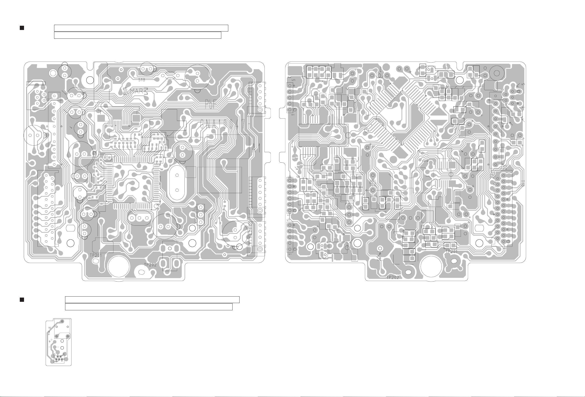
CD board
CN721
C7203
CN203
Lead free solder used in the board (material : Sn-Ag-Cu, melting point : 219 Centigrade)
Lead free solder used in the board (material : Sn-Cu, melting point : 230 Centigrade)
forward side reverse side
W601
C650
C612
C616
C624
IC721
C626
C625
C611
C630 C631
C615
C617
C618
C619
C620
R624
C621
C622
R670
C637
C636
R671
R625
C628
CN202
IC602
X601
C609
R660
C606
R607
R606
C602
C655
R601
L101
R608
C603
C605
C604
C644
C648
R605
X101
C105
R604
C610
Q601
R616
R617
R618
R108
R105
R613
R614
R615
R609
R610
R106
R107
C607
C608
C109
CN201
CN102
CN101
C638
R642
CN102CN201
R641
TP203
TP204
C651
C639
R643
CN101
R640
TP601
C652
R652
C642
C645
R645
R644
C653
R648
C109
Q101
R653
C106
R655
C647
C108
IC601
R654
C640
R647
R646
C107
D605
C103
Q601
IC102
C648
C654
R656
C649
R651
C110
R659
X101
R104
R669
C104
C105
L101
TP613
C662
C644
TP615
TP614
C122
R636
R637
C635
R103
R635
C632
C121
C609
R112
TP611
C643
R657
R658
TP612
X601
R611
Q602
IC101
TP602
C641
R649
C646
R650
R631
R634
R632
TP205
C102
R629
R630
C623
IC605
C629
R622
R612
R620
C627
C661
R621
C633
C614
C624
C631
R633
R668
C625
C626
R619
C650
C630
C616
C613
C612
C611
R102
IC721
R623
R101
C101
C660
W601
C7201
D7201
C7203
R672
CN721
C7202
CN203
Loader board
S201
Lead free solder used in the board (material : Sn-Ag-Cu, melting point : 219 Centigrade)
Lead free solder used in the board (material : Sn-Cu, melting point : 230 Centigrade)
S1
CN1
S201
2-10
Page 35

DAB module board
forward side
R87
Q82
C82
R83
R86
C83
Q81
R84
C93
R3
C2
C11
R6
C75
R141
C73
R85
R81
IC71
C81
R82
TU91
C92
C1
C6
C9
R91
C72
C74
Lead free solder used in the board (material : Sn-Ag-Cu, melting point : 219 Centigrade)
Lead free solder used in the board (material : Sn-Cu, melting point : 230 Centigrade)
R92
C91
R89
R88
R4
C94
C4
C7
C8
R5
R133
R132
R90
C5
C10
C71
R138
R137
R136
R134
R128
R127
R125
R131
CN141
R106
R104
R108
R107
R124
R123
R105
R103
R66
IC101
NC49
R122
R143
C104
C105
X101
C26
R113
D141
C103
R142
C101
C102
C21
C95
R99
R98
C90
R93
C3
C24
R1
R2
IC1
C12
C13
C51
C23
C25
C22
R94
R95
X1
R16
R15
C19
C20
R114
R115
R116
R117
C18
R118
R119
C106
R14
R9
R10
R11
R8
C14
C57
DAC9
IC51
C58
C16
R12
R120
C17
R13
C15
R63
C54
C56
C53
DAC12
R126
C191
IC191
R101
R102
C110
C109
R130
C107
KEY3
KEY1
NC94
SDCK
SDWD
SDDA
reverse side
/JBUSI/O
JBUSDAO
JBUSDAI
NC8
KEY2
NC95
KEY0
JBUSCK
NC79
INDO0
INDO2
JBUSI/O
NC7
NC10
NC87
LCDDB4
R110
R109
XO
CN101
AMUTEL
LCDRS
LCDDB2
R112
R111
SYSCKO
JBUSINT
NC35
NC38
NC40
AMUTER
LCKR/W
DISG0
TS_DAT
TS_CLK
DAOUT
DISG1
SDAT2
DISG2
CN121
DISG3
PWMVCXO
TS_SYNC
DDOWMSC
TU91
ADCOVR
NULMON
RDIOUT
FSYO
AGCDAT
SDODT
SDOCK
SDOWD
DDOERF
CN141
INDO1
INDO4
INDO6
LCDDB7
LCDDB6
INDO3
INDO7
AUDSEL
INDO5
LCDDB1
LCDDB5
LCDDB3
ANTPOW
LCDE
LCDDB0
2-11
Page 36

Victor Company of Japan, Limited
Audio/Video Systems Category 10-1,1chome,Ohwatari-machi,Maebashi-city,371-8543,Japan
(No.MB633SCH)
Printed in Japan
VPT
Page 37

PARTS LIST
UX-DAB11B,UX-DAB11EN
* All printed circuit boards and its assemblies are not available as service parts.
MB633
- Contents -
Exploded view of general assembly and parts list (Block No.M1)
CD mechanism assembly and parts list (Block No.MB)
CD loading base assembly and parts list (Block No.MD)
Electrical parts list (Block No.01~05)
Packing materials and accessories parts list (Block No.M3)
3- 2
3- 5
3- 7
3- 9
3-16
3-1
Page 38

Exploded view of general assembly and parts list
Block No.
M
M
1
M
21
1
6
x
4
43
48
E
A
2
36
5
Front board
j
43
H
7
12
7
7
42
c
9
7
a
f
3-2
Front View
40
41
a
16
3
e
Jack board
A
10
Page 39

21
20
26
g
D
Power board
b
37
25
39
19
d
15
15
11
b
8
Main board
15
13
47
E
38
38
g
38
18
39
9
r
j
46
DAB board
45
29
27
h
50
x
c
H
30
p
31
32
p
h
49
d
34
B
24
44
e
22
r
17
23
15
D
f
B
33
35
14
The parts without symbol number are not service.
3-3
Page 40

General Assembly
Symbol No. Part No. Part Name Description Local
1 GN10115-005A FRONT PANEL
2 GV40780-001A FELT SPACER (x2)
3 GN20222-005A WINDOW SCREEN
4 GN20223-002A PUSH BUTTON
5 GN20225-006A PUSH BUTTON
6 GN20226-002A ORNAMENT
7 QYSDSF2608ZA TAP SCREW M2.6 x 8mm(x7)
8 GV30349-050A SPACER
9 QYSDSG3008ZA TAP SCREW M3 x 8mm(x2)
10 GN10116-002A BOTTOM CHASSIS
11 GN30213-001A BRACKET A
12 GN30214-001A BRACKET B
13 GN30236-001A BRACKET C
14 GN30235-001A BRACKET D
15 QYSDSG3006EA TAP SCREW M3 x 6mm(x4)
16 QYSDSG3008ZA TAP SCREW M3 x 8mm(x2)
17 QYSDSG3008ZA TAP SCREW M3 x 8mm
18 GN30237-001A BRACKET E (x2)
19 QYSDSG3008ZA TAP SCREW M3 x 8mm(x2)
20 GV30792-005A SPACER PC
21 QYSDSG3008ZA TAP SCREW M3 x 8mm(x2)
22 QYSBSGY3008EA TAP SCREW M3 x 8mm
23 QYSBSGY3008EA TAP SCREW M3 x 8mm
24 GV40764-001A FOOT SPACER (x2)
25 QMPN410-200-JD POWER CORD 2m BLACK B
25 QMPK200-200-JD POWER CORD 2m BLACK EN
26 QZW0033-001 STRAIN RELIEF
27 QAU0473-001 TUNER
29 QUQU12-1515BJ-E FFC WIRE 15pin 15cm
30 QUQU12-1313AJ-E FFC WIRE 13pin 13cm
31 GN10117-212A REAR PANEL
32 QYSBSGY3008EA TAP SCREW M3 x 8mm(x2)
33 QYSBSGY3008EA TAP SCREW M3 x 8mm(x2)
34 GV40711-001A NUT
35 QYSBSGY3008EA TAP SCREW M3 x 8mm(x2)
36 QYSDSG3008ZA TAP SCREW M3 x 8mm(x2)
37 GN20229-004A/S/ METAL COVER
38 QYSBSGY3008EA TAP SCREW M3 x 8mm(x6)
39 QYSDSG3008NA TAP SCREW M3 x 8mm(x2)
40 GN30216-002A TRAY FITTING
41 GN30217-002A VOLUME KNOB
42 QYSBSG3010ZA TAP SCREW M3 x 10mm
43 GN30006-036A SPACER (x2)
44 QYSBST3008ZA TAP SCREW M3 x 8mm
45 GV31088-001A HEAT SINK
46 GV40791-001A THERMAL SHEET
47 QMFZ059-2R0-E FUSE 2A
48 QUR110-2014AJ-E FFC WIRE
49 GV30349-050A SPACER
50 GV30349-050A SPACER
Block No. [M][1][M][M]
3-4
Page 41

CD mechanism assembly and parts list
Grease
JVG-31N
JVS-1003
FL-7750E
E-460
GTU-MS1-21M
Block No.
M
M
B
M
3
14
0.1mm
18mm
16
13
17
12.0mm 0.1mm
14
13
7
8
2
6
9
7
4
10
5
A
1
20
23
a
19
12
11
18
A
6
3.2mm
11
0.1mm
12
15
9
< Back side >
24
21
22
26
CD servo board
a
25
The parts without symbol number are not service.
3-5
Page 42

CD mechanism
Symbol No. Part No. Part Name Description Local
1 QAL0844-001 PICK UP
2 LV22529-003A RACK ARM
3 VKZ4777-012 MINI SCREW (x2)
4 LV37574-001A RACK ARM SPRING
5 QYSPSGT1425MA TAP SCREW M1.4 x 2.5mm
6 LV10855-004A TM CHASISS
7 LV43648-001A TURN TABLE
8 LV31744-001A P.S.SPRING
9 QAR0302-001 SPINDLE MOTOR 2.0V DC
10 VKZ4743-002 SPECIAL SCREW (x2)
11 LV40157-001A SCREW SHAFT
12 LV43651-001A SS GEAR
13 LV43650-001A F MOTOR GEAR
14 QAR0303-001 FEED MOTOR 2.0V DC
15 QYSPSPT2030MA SCREW M2 x 3mm
16 QUB549-07A1A1-E SIN TWIST WIRE
17 QUB544-07A1A1-E SIN TWIST WIRE
18 LV34565-003A F MIDDLE GEAR
19 LV34563-002A SHAFT HOLDER
20 QYSPSFT1740ZA TAP SCREW M1.7 x 4mm
21 QYSBSF2006ZA TAP SCREW M2 x 6mm(x2)
22 LV30225-073A SPACER
23 QUQU05-1506BB-E FFC WIRE 15pin 6cm
24 QUR110-2313BJ-E FFC WIRE
25 GV40774-002A COVER SHEET
26 LV30225-0F4A SPACER
Block No. [M][B][M][M]
3-6
Page 43
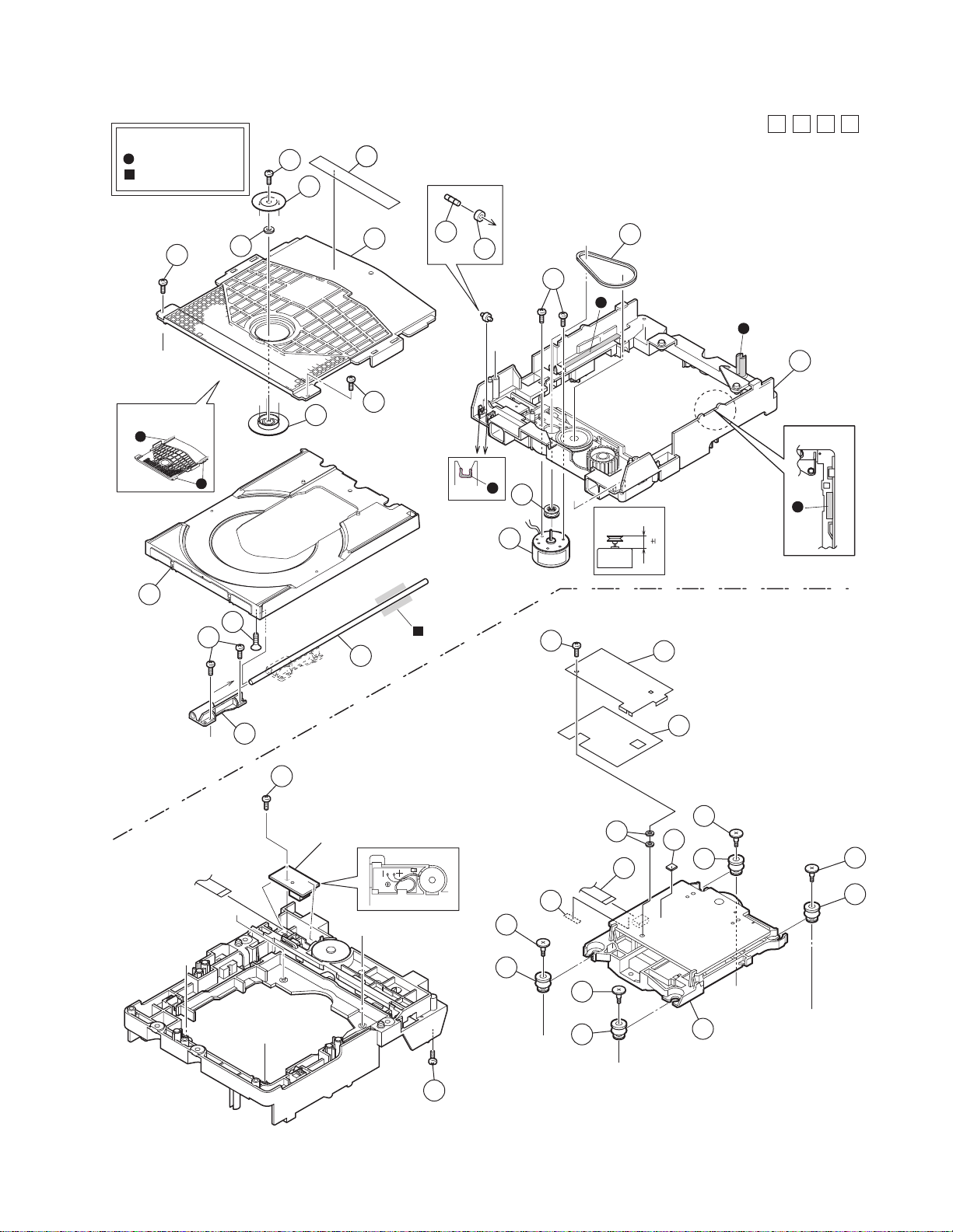
CD loading base assembly and parts list
Grease
JVS-1003
CFD-4007ZY2
20
25
19
GMU-MS1-21M
Block No.
M
D
M
M
14
h
< Back side >
4
18
17
7
8
15
14
6
2
3
12
h
11
10
j
30
16
1
< Top view >
0.10mm
7.75mm
Backside
28
27
31
24
22
21
24
22
e
f
5
j
13
24
23
29
32
k
CD loading switch board
k
e
f
c
d
26
24
23
c
d
9
The parts without symbol number are not service.
3-7
Page 44

CD loading base
Symbol No. Part No. Part Name Description Local
1 LV11065-010A LOADER SUB ASSY
2 E407140-001SS C.D ROLLER
3 E407149-001SS RUBBER TUBE
4 LV10979-003A TRAY
5 LV35499-003A SHAFT GUIDE
6 LV44022-001A SHAFT
7 QYSSSF2008ZA SCREW
8 QYSDSF2008ZA SCREW (x2)
9 LV41741-004A SPECIAL SCREW
10 QAR0197-001 MOTOR
10 or QAR0450-001 MOTOR
11 LV43844-002A MOTOR PULLEY
12 QYSPSPU1730ZA SCREW (x2)
13 QYSDSF2008ZA SCREW
14 QYSDSF2008ZA SCREW (x2)
15 LV21852-003A CLAMPER BASE
16 LV43974-001A BELT
17 LV34586-002A CD CLAMPER
18 LV42930-003A P.C.MAGNET
19 LV43848-001A YOKE
20 LV43958-001A SPECIAL SCREW
21 ------------ CD TRAMECHA UNI
22 LV44043-001A INSULATOR (x2)
23 LV44043-002A INSULATOR (x2)
24 LV44044-001A SPECIAL SCREW (x4)
25 LV44603-003A LASER CAUTION
26 LV30225-0V6A SPACER
27 GV30349-081A SPACER
28 GV40776-001A BRACKET
29 GV30792-004A SPACER (x2)
30 QYSBSF2008ZA TAP SCREW M2 x 8mm
31 GV40789-002A SPACER
32 LV43805-002A FFC
Block No. [M][D][M][M]
3-8
Page 45

Electrical parts list
Power board
Block No. [0][1]
Symbol No.
IC221 PT6315 IC
IC241 NJL23H380A-E IC
IC401 NJM4565M-WE IC
IC901 MIP4190MDSLJ IC
IC902 KIA431A-T IC
IC903 PQ1CG21H2FZ IC Regulator
Part No. Part Name Description Local
Symbol No.
C4306 NDC31HJ-101X C CAPACITOR 100pF 50V J
C4351 NRSA63J-0R0X MG RESISTOR 0Ω 1/16W J
C4399 NRSA63J-0R0X MG RESISTOR 0Ω 1/16W J
C4651 NRSA63J-0R0X MG RESISTOR 0Ω 1/16W J
C8106 NCB31CK-104X C CAPACITOR 0.1uF 16V K
C8206 NCB31CK-104X C CAPACITOR 0.1uF 16V K
C8305 NCB20JK-155X C CAPACITOR 1.5uF 6.3V K
C8306 NRSA63J-0R0X MG RESISTOR 0Ω 1/16W J
C8307 NCB31CK-104X C CAPACITOR 0.1uF 16V K
C8351 NRSA63J-0R0X MG RESISTOR 0Ω 1/16W J
Part No. Part Name Description Local
D101 STZC6.8N-X USB ESD DIODE
D901 KBJ4J BRIDGE DIODE
D902 SF27-B351C FR DIODE
D903 SF27-B351C FR DIODE
D904 1SS244-T2 SI DIODE
D905 MA2SD32-X DIODE
D951 FR104S-T5 FR DIODE
D952 EC30HA04-X SB DIODE
D953 FR104S-T5 FR DIODE
D954 MBR10150CT DIODE
D955 MTZJ6.8B-T2 Z DIODE
D2411 SLR-343VC/NPQ-T LED
PC901 PC123Y22FZ PHOTO COUPLER
C111 NCB31HK-182X C CAPACITOR 1800pF 50V K
C112 NCB31HK-182X C CAPACITOR 1800pF 50V K
C114 NDC31HJ-150X C CAPACITOR 15pF 50V J
C115 NDC31HJ-150X C CAPACITOR 15pF 50V J
C901 QCZ9134-102 C CAPACITOR 1000pF
C902 QFZ9073-683 MM CAPACITOR 0.068uF AC250V M
C903 QCZ9134-101 C CAPACITOR 100pF
C904 QCZ9134-102 C CAPACITOR 1000pF
C905 QFZ9073-154 MM CAPACITOR 0.15uF AC250V M
C906 QCZ9134-101 C CAPACITOR 100pF
C907 QEZ0827-107 E CAPACITOR 100uF
C908 QCZ0136-331Z C CAPACITOR 330pF 1kV K
C909 QCZ0134-472 C CAPACITOR 4700pF
C910 QEZ0658-476Z E CAPACITOR 47uF 50V M
C911 QCZ0136-331Z C CAPACITOR 330pF 1kV K
C912 NCB31CK-104X C CAPACITOR 0.1uF 16V K
C913 NCB31HK-104X C CAPACITOR 0.1uF 50V K
C914 NDC31HJ-120X C CAPACITOR 12pF 50V J
C915 QETN1HM-225Z E CAPACITOR 2.2uF 50V M
C916 NDC31HJ-331X C CAPACITOR 330pF 50V J
C917 NCB31CK-104X C CAPACITOR 0.1uF 16V K
C918 QCZ9134-102 C CAPACITOR 1000pF
C919 QCZ0134-472 C CAPACITOR 4700pF
C920 NCB31HK-222X C CAPACITOR 2200pF 50V K
C951 QEZ0658-396Z E CAPACITOR 39uF 50V M
C953 QETN1EM-227Z E CAPACITOR 220uF 25V M
C954 QEZ0654-108Z E CAPACITOR 1000uF 10V M
C955 QETN1AM-477Z E CAPACITOR 470uF 10V M
C956 NCB31CK-104X C CAPACITOR 0.1uF 16V K
C957 QEZ0656-687Z E CAPACITOR 680uF
C958 QETN1EM-227Z E CAPACITOR 220uF 25V M
C960 NCB31CK-105X C CAPACITOR 1uF 16V K
C961 QEZ0656-687Z E CAPACITOR 680uF
C962 QEZ0656-687Z E CAPACITOR 680uF
C2201 NCB31CK-104X C CAPACITOR 0.1uF 16V K
C2204 NCB31CK-104X C CAPACITOR 0.1uF 16V K
C2205 NCB31HK-223X C CAPACITOR 0.022uF 50V K
C2207 NCF31AZ-105X C CAPACITOR 1uF 10V Z
C2209 QERF0JM-226Z E CAPACITOR 22uF 6.3V M
C2210 NCB31HK-472X C CAPACITOR 4700pF 50V K
C2601 NCB31HK-103X C CAPACITOR 0.01uF 50V K
C2602 NCB31HK-103X C CAPACITOR 0.01uF 50V K
C2901 NCF31HZ-103X C CAPACITOR 0.01uF 50V Z
C4152 NDC31HJ-221X C CAPACITOR 220pF 50V J
C4252 NDC31HJ-221X C CAPACITOR 220pF 50V J
C4301 QETN1EM-476Z E CAPACITOR 47uF 25V M
C4302 QETN1EM-476Z E CAPACITOR 47uF 25V M
C4303 QETN1HM-225Z E CAPACITOR 2.2uF 50V M
C4304 QETN1HM-225Z E CAPACITOR 2.2uF 50V M
C4305 NDC31HJ-101X C CAPACITOR 100pF 50V J
R901 QRZ9037-335 COMP RESISTOR 3.3MΩ 1/2W K
R903 QRL02DJ-223X OMF RESISTOR 22kΩ 2W J
R904 NRSA63J-683X MG RESISTOR 68kΩ 1/16W J
R905 NRSA63J-563X MG RESISTOR 56kΩ 1/16W J
R908 NRSA63J-332X MG RESISTOR 3.3kΩ 1/16W J
R909 NRSA63J-432X MG RESISTOR 4.3kΩ 1/16W J
R910 QRE141J-100Y C RESISTOR 10Ω 1/4W J
R951 NRSA63J-752X MG RESISTOR 7.5kΩ 1/16W J
R952 NRSA63J-152X MG RESISTOR 1.5k
R953 NRSA63J-113X MG RESISTOR 11k
R954 NRSA63J-102X MG RESISTOR 1kΩ 1/16W J
R955 NRSA63J-202X MG RESISTOR 2kΩ 1/16W J
R957 NRSA63J-392X MG RESISTOR 3.9kΩ 1/16W J
R958 NRSA63J-102X MG RESISTOR 1kΩ 1/16W J
R959 QRZ9005-100X FUSI RESISTOR 10
R2203 NRSA63J-104X MG RESISTOR 100kΩ 1/16W J
R2206 NRSA63J-103X MG RESISTOR 10kΩ 1/16W J
R2207 NRSA63J-0R0X MG RESISTOR 0Ω 1/16W J
R2411 NRSA63J-240X MG RESISTOR 24Ω 1/16W J
R2501 NRSA63J-431X MG RESISTOR 430Ω 1/16W J
R2502 NRSA63J-511X MG RESISTOR 510Ω 1/16W J
R2503 NRSA63J-122X MG RESISTOR 1.2kΩ 1/16W J
R2504 NRSA63J-431X MG RESISTOR 430Ω 1/16W J
R2505 NRSA63J-511X MG RESISTOR 510Ω 1/16W J
R4151 NRSA63J-133X MG RESISTOR 13kΩ 1/16W J
R4152 NRSA63J-513X MG RESISTOR 51kΩ 1/16W J
R4251 NRSA63J-133X MG RESISTOR 13kΩ 1/16W J
R4252 NRSA63J-513X MG RESISTOR 51kΩ 1/16W J
R4301 NRSA63J-473X MG RESISTOR 47kΩ 1/16W J
R4302 NRSA63J-473X MG RESISTOR 47kΩ 1/16W J
R4303 NRSA63J-104X MG RESISTOR 100kΩ 1/16W J
R4304 NRSA63J-104X MG RESISTOR 100kΩ 1/16W J
R4305 NRSA63J-102X MG RESISTOR 1kΩ 1/16W J
R4306 NRSA63J-102X MG RESISTOR 1kΩ 1/16W J
R8302 NRSA63J-102X MG RESISTOR 1kΩ 1/16W J
L901 QQR1800-001 LINE FILTER
L902 QQR1800-001 LINE FILTER
L952 QQL50AK-221Z COIL 220uH K
L954 QQLZ037-220 COIL 22uH
T901 QQS0404-001 SW TRANSF
CN103 or QNZ0926-001 USB CONNECTOR
CN103 QNZ0851-001 USB CONNECTOR
CN104 QGA2001C1-05 CONNECTOR W-B (1-5)
CN221 QGF1040F1-20 CONNECTOR FFC/FPC (1-20)
CN402 QGB1214K1-10S CONNECTOR B-B (1-10)
CN701 QGF1040F1-23 CONNECTOR FFC/FPC (1-23)
CN702 QGB1214K1-20S CONNECTOR B-B (1-20)
CN901 QGB2510K2-10 CONNECTOR B-B (1-10)
CP901 ICP-N10-T IC PROTECTOR 400mA
CP901 or QMFZ050-1R5X-E FUSE 1.5A 125V
CP902 ICP-N20-T IC PROTECTOR 800mA
DI221 QLF0186-001 FL TUBE
DI221 or QLF0190-001 FL TUBE
FC901 QNG0003-001Z FUSE CLIP
FC902 QNG0003-001Z FUSE CLIP
HS901 GN40147-001A HEAT SINK
J4351 QNS0188-001 JACK
J4352 QNS0188-001 JACK
J8001 QNS0188-001 JACK
JS261 QSW1130-001 ROTARY ENCODER
K102 NQR0502-002X FERRITE BEADS
K103 NQR0502-002X FERRITE BEADS
K105 NQR0022-002X FERRITE BEADS
Ω
1/16W J
Ω
1/16W J
Ω
3-9
Page 46

Symbol No.
Part No. Part Name Description Local
Symbol No.
Part No. Part Name Description Local
K106 NQR0022-002X FERRITE BEADS
K4351 NRSA63J-0R0X MG RESISTOR 0Ω 1/16W J
K4602 NRSA63J-0R0X MG RESISTOR 0Ω 1/16W J
K8101 NQR0389-003X FERRITE BEADS
K8201 NQR0389-003X FERRITE BEADS
K8301 NQR0389-003X FERRITE BEADS
P901 QGA7901C1-02 CONNECTOR W-B (1-2)
S2501 QSW0825-001Z TACT SW
S2502 QSW0825-001Z TACT SW
S2503 QSW0825-001Z TACT SW
S2504 QSW0825-001Z TACT SW
S2505 QSW0825-001Z TACT SW
S2506 QSW0825-001Z TACT SW
S2507 QSW0825-001Z TACT SW
S2509 QSW0825-001Z TACT SW
S2510 QSW0825-001Z TACT SW
S2511 QSW0825-001Z TACT SW
S2512 QSW0825-001Z TACT SW
W901 QZW0112-001 WIRE CLAMP
Input board
Block No. [0][2]
Symbol No.
IC303 LC75345M-X IC
IC372 RT9164A-PG-X IC
IC373 MM1594AF-X IC
IC374 MM1565AF-X IC
IC452 NJM4565M-WE IC
IC452 or LM358DR-X IC
IC501 TPA3100D2PHP-W IC
IC701 MN101EF16KXW MICON IC
IC702 BR24L04F-W-X IC
IC801 NJM4565M-WE IC
Q3401 KTA1023/OY/-T TRANSISTOR
Q3402 2SC3928A/QR/-X TRANSISTOR
Q3501 KTA1046/Y/ TRANSISTOR
Q3502 2SC3928A/QR/-X TRANSISTOR
Q3601 2SC5938A/B/-X TRANSISTOR
Q3602 2SC5938A/B/-X TRANSISTOR
Q3701 2SC3576-JVC-T TRANSISTOR
Q3702 RT1P441C-X DIGI TRANSISTOR
Q3705 KTA1023/OY/-T TRANSISTOR
Q3706 2SC3928A/QR/-X TRANSISTOR
Q3710 KTA1267/YG/-T TRANSISTOR
Q3801 KTA1023/OY/-T TRANSISTOR
Q3802 2SC3928A/QR/-X TRANSISTOR
Q4501 RT1N44HC-X DIGI TRANSISTOR
Q4502 ISA1530AC1/QR/X TRANSISTOR
Q4503 RT1N431C-X TRANSISTOR
Q4601 IMX9-W TRANSISTOR
Q4603 RT1P441C-X DIGI TRANSISTOR
Q4604 IMX9-W TRANSISTOR
Q4606 RT1P141C-X DIGI TRANSISTOR
Q7001 RT1N430C-X TRANSISTOR
Q7002 RT1N430C-X TRANSISTOR
Q8102 IMX9-W TRANSISTOR
Q8103 IMX9-W TRANSISTOR
Q8301 RT1P431C-X DIGI TRANSISTOR
D3305 MC2838-X DIODE
D3401 1SS133-T2 SI DIODE
D3402 MTZJ6.8B-T2 Z DIODE
D3403 1SS133-T2 SI DIODE
D3501 MTZJ4.3B-T2 Z DIODE
D3502 1SS133-T2 SI DIODE
D3503 1SS133-T2 SI DIODE
D3504 1N4003S-T5 SI DIODE
D3506 1N4003S-T5 SI DIODE
D3507 1N4003S-T5 SI DIODE
D3701 MTZJ30C-T2 Z DIODE
D3702 MTZJ10B-T2 Z DIODE
Part No. Part Name Description Local
D3703 FR104S-T5 FR DIODE
D3704 1SS133-T2 SI DIODE
D3705 MTZJ2.4B-T2 Z DIODE
D3708 1SS355-X SI DIODE
D3710 1N4003S-T5 SI DIODE
D3801 MTZJ12B-T2 Z DIODE
D3802 MTZJ3.3B-T2 Z DIODE
D3803 1SS133-T2 SI DIODE
D4501 1SS133-T2 SI DIODE
D5001 MC2838-X DIODE
D5101 MC2838-X DIODE
D5301 MC2838-X DIODE
D7001 1SS133-T2 SI DIODE
D7002 MTZJ3.3B-T2 Z DIODE
D7004 MA111-X SI DIODE
C3140 QFVF1HJ-154Z MF CAPACITOR 0.15uF 50V J
C3141 QFVF1HJ-154Z MF CAPACITOR 0.15uF 50V J
C3142 QFVF1HJ-104Z MF CAPACITOR 0.1uF 50V J
C3143 QFVF1HJ-104Z MF CAPACITOR 0.1uF 50V J
C3144 QFLC1HJ-272Z M CAPACITOR 2700pF 50V J
C3145 QETN1HM-475Z E CAPACITOR 4.7uF 50V M
C3148 QETN1HM-104Z E CAPACITOR 0.1uF 50V M
C3149 QTE1J46-106Z E CAPACITOR 10uF 63V
C3150 QETN1HM-226Z E CAPACITOR 22uF 50V M
C3151 NCB31HK-223X C CAPACITOR 0.022uF 50V K
C3152 NCB31EK-683X C CAPACITOR 0.068uF 25V K
C3153 NCB31EK-683X C CAPACITOR 0.068uF 25V K
C3154 QFVF1HJ-474Z MF CAPACITOR 0.47uF 50V J
C3155 QETN1HM-475Z E CAPACITOR 4.7uF 50V M
C3156 QETN1HM-475Z E CAPACITOR 4.7uF 50V M
C3159 QETN1HM-475Z E CAPACITOR 4.7uF 50V M
C3240 QFVF1HJ-154Z MF CAPACITOR 0.15uF 50V J
C3241 QFVF1HJ-154Z MF CAPACITOR 0.15uF 50V J
C3242 QFVF1HJ-104Z MF CAPACITOR 0.1uF 50V J
C3243 QFVF1HJ-104Z MF CAPACITOR 0.1uF 50V J
C3244 QFLC1HJ-272Z M CAPACITOR 2700pF 50V J
C3245 QETN1HM-475Z E CAPACITOR 4.7uF 50V M
C3248 QETN1HM-104Z E CAPACITOR 0.1uF 50V M
C3249 QTE1J46-106Z E CAPACITOR 10uF 63V
C3250 QETN1HM-226Z E CAPACITOR 22uF 50V M
C3251 NCB31HK-223X C CAPACITOR 0.022uF 50V K
C3252 NCB31EK-683X C CAPACITOR 0.068uF 25V K
C3253 NCB31EK-683X C CAPACITOR 0.068uF 25V K
C3254 QFVF1HJ-474Z MF CAPACITOR 0.47uF 50V J
C3255 QETN1HM-475Z E CAPACITOR 4.7uF 50V M
C3256 QETN1HM-475Z E CAPACITOR 4.7uF 50V M
C3259 QETN1HM-475Z E CAPACITOR 4.7uF 50V M
C3311 QETN1HM-105Z E CAPACITOR 1uF 50V M
C3312 QETN1HM-106Z E CAPACITOR 10uF 50V M
C3341 QETN1AM-227Z E CAPACITOR 220uF 10V M
C3342 QETN1AM-227Z E CAPACITOR 220uF 10V M
C3401 QETN1HM-106Z E CAPACITOR 10uF 50V M
C3402 NCB31HK-103X C CAPACITOR 0.01uF 50V K
C3404 QETN1CM-107Z E CAPACITOR 100uF 16V M
C3501 QETN1HM-106Z E CAPACITOR 10uF 50V M
C3502 NCB31HK-103X C CAPACITOR 0.01uF 50V K
C3503 QETN1CM-107Z E CAPACITOR 100uF 16V M
C3511 QETN1CM-477Z E CAPACITOR 470uF 16V M
C3705 QETN1HM-106Z E CAPACITOR 10uF 50V M
C3706 QETN1CM-107Z E CAPACITOR 100uF 16V M
C3711 NCF31CZ-104X C CAPACITOR 0.1uF 16V Z
C3712 QETN1CM-107Z E CAPACITOR 100uF 16V M
C3714 NCF31CZ-104X C CAPACITOR 0.1uF 16V Z
C3715 QETN1CM-107Z E CAPACITOR 100uF 16V M
C3716 NCB31HK-471X C CAPACITOR 470pF 50V K
C3717 NCF31CZ-104X C CAPACITOR 0.1uF 16V Z
C3718 QETN1CM-107Z E CAPACITOR 100uF 16V M
C3719 NCB31CK-105X C CAPACITOR 1uF 16V K
C3720 NCB31CK-105X C CAPACITOR 1uF 16V K
C3721 NCB31HK-471X C CAPACITOR 470pF 50V K
C3723 QETN1CM-107Z E CAPACITOR 100uF 16V M
C3801 QETN1EM-476Z E CAPACITOR 47uF 25V M
C3802 QETN1CM-107Z E CAPACITOR 100uF 16V M
C3803 NCB31HK-103X C CAPACITOR 0.01uF 50V K
C4501 QETN1HM-106Z E CAPACITOR 10uF 50V M
C4502 QETN1EM-476Z E CAPACITOR 47uF 25V M
C4503 QETN1EM-476Z E CAPACITOR 47uF 25V M
3-10
Page 47

Symbol No.
Part No. Part Name Description Local
Symbol No.
Part No. Part Name Description Local
C4510 NCB31CK-224X C CAPACITOR 0.22uF 16V K
C4601 NDC31HJ-471X C CAPACITOR 470pF 50V J
C4602 NDC31HJ-471X C CAPACITOR 470pF 50V J
C4603 QETN1HM-106Z E CAPACITOR 10uF 50V M
C4607 NDC31HJ-101X C CAPACITOR 100pF 50V J
C4608 NDC31HJ-101X C CAPACITOR 100pF 50V J
C5101 NDC31HJ-331X C CAPACITOR 330pF 50V J
C5102 NCB21AK-225X C CAPACITOR 2.2uF 10V K
C5103 QTE1J46-106Z E CAPACITOR 10uF 63V
C5104 NCB21CK-105X C CAPACITOR 1uF 16V K
C5105 NCB21HK-104X C CAPACITOR 0.1uF 50V K
C5106 NCB21HK-104X C CAPACITOR 0.1uF 50V K
C5107 NCB31HK-223X C CAPACITOR 0.022uF 50V K
C5108 NCB31HK-223X C CAPACITOR 0.022uF 50V K
C5112 NCB31HK-332X C CAPACITOR 3300pF 50V K
C5113 NCB21EK-224X C CAPACITOR 0.22uF 25V K
C5114 NCB21EK-224X C CAPACITOR 0.22uF 25V K
C5115 QETN1HM-106Z E CAPACITOR 10uF 50V M
C5116 QETN1HM-106Z E CAPACITOR 10uF 50V M
C5117 NCB31AK-334X C CAPACITOR 0.33uF 10V K
C5118 NCB31AK-334X C CAPACITOR 0.33uF 10V K
C5119 NCB31CK-224X C CAPACITOR 0.22uF 16V K
C5120 NCB31CK-224X C CAPACITOR 0.22uF 16V K
C5122 NCB31HK-103X C CAPACITOR 0.01uF 50V K
C5123 NCB31HK-103X C CAPACITOR 0.01uF 50V K
C5201 NDC31HJ-331X C CAPACITOR 330pF 50V J
C5202 NCB21AK-225X C CAPACITOR 2.2uF 10V K
C5203 QTE1J46-106Z E CAPACITOR 10uF 63V
C5204 NCB21CK-105X C CAPACITOR 1uF 16V K
C5205 NCB21HK-104X C CAPACITOR 0.1uF 50V K
C5206 NCB21HK-104X C CAPACITOR 0.1uF 50V K
C5207 NCB31HK-223X C CAPACITOR 0.022uF 50V K
C5208 NCB31HK-223X C CAPACITOR 0.022uF 50V K
C5212 NCB31HK-332X C CAPACITOR 3300pF 50V K
C5213 NCB21EK-224X C CAPACITOR 0.22uF 25V K
C5214 NCB21EK-224X C CAPACITOR 0.22uF 25V K
C5215 QETN1HM-106Z E CAPACITOR 10uF 50V M
C5216 QETN1HM-106Z E CAPACITOR 10uF 50V M
C5217 NCB31AK-334X C CAPACITOR 0.33uF 10V K
C5218 NCB31AK-334X C CAPACITOR 0.33uF 10V K
C5219 NCB31CK-224X C CAPACITOR 0.22uF 16V K
C5220 NCB31CK-224X C CAPACITOR 0.22uF 16V K
C5222 NCB31HK-103X C CAPACITOR 0.01uF 50V K
C5223 NCB31HK-103X C CAPACITOR 0.01uF 50V K
C5303 NCB31HK-103X C CAPACITOR 0.01uF 50V K
C5304 NCB21AK-225X C CAPACITOR 2.2uF 10V K
C5305 NCB31HK-104X C CAPACITOR 0.1uF 50V K
C5306 QETN1EM-227Z E CAPACITOR 220uF 25V M
C5307 NCB31CK-105X C CAPACITOR 1uF 16V K
C5308 NCB31CK-105X C CAPACITOR 1uF 16V K
C5309 QETN1EM-227Z E CAPACITOR 220uF 25V M
C5310 NCB31HK-104X C CAPACITOR 0.1uF 50V K
C5312 QETN1HM-226Z E CAPACITOR 22uF 50V M
C7001 QETN1HM-106Z E CAPACITOR 10uF 50V M
C7003 NDC31HJ-151X C CAPACITOR 150pF 50V J
C7004 QRE141J-131Y C RESISTOR 130
C7005 NCB31CK-104X C CAPACITOR 0.1uF 16V K
C7006 QETN1CM-107Z E CAPACITOR 100uF 16V M
C7009 NDC31HJ-220X C CAPACITOR 22pF 50V J
C7010 NDC31HJ-220X C CAPACITOR 22pF 50V J
C7012 NCB31CK-104X C CAPACITOR 0.1uF 16V K
C7013 NCB31CK-104X C CAPACITOR 0.1uF 16V K
C7014 NCB31CK-104X C CAPACITOR 0.1uF 16V K
C7015 NCB31CK-104X C CAPACITOR 0.1uF 16V K
C7016 NCB31CK-473X C CAPACITOR 0.047uF 16V K
C7017 NCB31CK-104X C CAPACITOR 0.1uF 16V K
C7018 NCF31AZ-105X C CAPACITOR 1uF 10V Z
C8101 QETN1HM-106Z E CAPACITOR 10uF 50V M
C8103 NDC31HJ-151X C CAPACITOR 150pF 50V J
C8104 NCB31HK-222X C CAPACITOR 2200pF 50V K
C8105 QETN1AM-227Z E CAPACITOR 220uF 10V M
C8107 QETN1HM-475Z E CAPACITOR 4.7uF 50V M
C8201 QETN1HM-106Z E CAPACITOR 10uF 50V M
C8203 NDC31HJ-151X C CAPACITOR 150pF 50V J
C8204 NCB31HK-222X C CAPACITOR 2200pF 50V K
C8205 QETN1AM-227Z E CAPACITOR 220uF 10V M
C8207 QETN1HM-475Z E CAPACITOR 4.7uF 50V M
C8301 QETN1HM-475Z E CAPACITOR 4.7uF 50V M
Ω
1/4W J
C8303 QETN1CM-107Z E CAPACITOR 100uF 16V M
C8304 QETN1EM-476Z E CAPACITOR 47uF 25V M
C9001 NCF31HZ-103X C CAPACITOR 0.01uF 50V Z
C9004 NCB31HK-102X C CAPACITOR 1000pF 50V K
C9005 QETN1CM-227Z E CAPACITOR 220uF 16V M
C9007 NRSA63J-0R0X MG RESISTOR 0
R3140 NRSA63J-153X MG RESISTOR 15k
R3141 NRSA63J-752X MG RESISTOR 7.5kΩ 1/16W J
R3142 NRSA63J-473X MG RESISTOR 47kΩ 1/16W J
R3143 NRSA63J-223X MG RESISTOR 22kΩ 1/16W J
R3144 NRSA63J-472X MG RESISTOR 4.7kΩ 1/16W J
R3145 NRSA63J-222X MG RESISTOR 2.2kΩ 1/16W J
R3146 NRSA63J-182X MG RESISTOR 1.8kΩ 1/16W J
R3147 NRSA63J-622X MG RESISTOR 6.2kΩ 1/16W J
R3148 NRSA63J-224X MG RESISTOR 220kΩ 1/16W J
R3149 NRSA63J-683X MG RESISTOR 68kΩ 1/16W J
R3150 NRSA63J-153X MG RESISTOR 15kΩ 1/16W J
R3152 NRSA63J-102X MG RESISTOR 1kΩ 1/16W J
R3155 NRSA63J-392X MG RESISTOR 3.9kΩ 1/16W J
R3157 NRSA63J-102X MG RESISTOR 1k
R3158 NRSA63J-0R0X MG RESISTOR 0
R3240 NRSA63J-153X MG RESISTOR 15kΩ 1/16W J
R3241 NRSA63J-752X MG RESISTOR 7.5kΩ 1/16W J
R3242 NRSA63J-473X MG RESISTOR 47kΩ 1/16W J
R3243 NRSA63J-223X MG RESISTOR 22kΩ 1/16W J
R3244 NRSA63J-472X MG RESISTOR 4.7kΩ 1/16W J
R3245 NRSA63J-222X MG RESISTOR 2.2kΩ 1/16W J
R3246 NRSA63J-182X MG RESISTOR 1.8kΩ 1/16W J
R3247 NRSA63J-622X MG RESISTOR 6.2kΩ 1/16W J
R3248 NRSA63J-224X MG RESISTOR 220kΩ 1/16W J
R3249 NRSA63J-683X MG RESISTOR 68kΩ 1/16W J
R3250 NRSA63J-153X MG RESISTOR 15kΩ 1/16W J
R3252 NRSA63J-102X MG RESISTOR 1kΩ 1/16W J
R3255 NRSA63J-392X MG RESISTOR 3.9kΩ 1/16W J
R3257 NRSA63J-102X MG RESISTOR 1kΩ 1/16W J
R3258 NRSA63J-0R0X MG RESISTOR 0Ω 1/16W J
R3308 NRSA63J-224X MG RESISTOR 220kΩ 1/16W J
R3309 NRSA63J-124X MG RESISTOR 120kΩ 1/16W J
R3310 NRSA63J-223X MG RESISTOR 22kΩ 1/16W J
R3341 NRSA63J-330X MG RESISTOR 33Ω 1/16W J
R3342 NRSA63J-472X MG RESISTOR 4.7kΩ 1/16W J
R3343 NRSA63J-472X MG RESISTOR 4.7kΩ 1/16W J
R3344 NRSA63J-472X MG RESISTOR 4.7kΩ 1/16W J
R3401 QRE141J-471Y C RESISTOR 470Ω 1/4W J
R3402 NRSA63J-472X MG RESISTOR 4.7kΩ 1/16W J
R3411 NRSA63J-103X MG RESISTOR 10kΩ 1/16W J
R3412 NRSA63J-222X MG RESISTOR 2.2kΩ 1/16W J
R3501 NRSA63J-822X MG RESISTOR 8.2kΩ 1/16W J
R3502 QRE141J-271Y C RESISTOR 270
R3503 NRSA63J-473X MG RESISTOR 47kΩ 1/16W J
R3504 NRSA63J-133X MG RESISTOR 13k
R3701 NRSA63J-152X MG RESISTOR 1.5k
R3702 NRSA63J-103X MG RESISTOR 10kΩ 1/16W J
R3703 NRSA63J-103X MG RESISTOR 10k
R3704 QRE141J-5R1Y C RESISTOR 5.1
R3708 NRSA63J-562X MG RESISTOR 5.6kΩ 1/16W J
R3709 QRE141J-471Y C RESISTOR 470
R3712 NRSA63J-472X MG RESISTOR 4.7kΩ 1/16W J
R3713 NRSA63F-121X MG RESISTOR 120
R3714 NRSA63F-301X MG RESISTOR 300
R3715 QRE141J-332Y C RESISTOR 3.3kΩ 1/4W J
R3716 NRSA63J-103X MG RESISTOR 10k
R3801 NRSA63J-472X MG RESISTOR 4.7k
R3802 NRSA63J-471X MG RESISTOR 470Ω 1/16W J
R3803 QRE141J-821Y C RESISTOR 820
R3807 NRSA63J-0R0X MG RESISTOR 0
R4501 NRSA63J-472X MG RESISTOR 4.7k
R4502 NRSA63J-472X MG RESISTOR 4.7k
R4503 NRSA63J-224X MG RESISTOR 220kΩ 1/16W J
R4504 NRSA63J-104X MG RESISTOR 100k
R4505 NRSA63J-222X MG RESISTOR 2.2k
R4506 NRSA63J-473X MG RESISTOR 47kΩ 1/16W J
R4507 NRSA63J-473X MG RESISTOR 47k
R4512 NRSA63J-272X MG RESISTOR 2.7k
R4513 NRSA63J-103X MG RESISTOR 10kΩ 1/16W J
R4514 NRSA63J-102X MG RESISTOR 1k
R4601 NRSA63J-102X MG RESISTOR 1k
Ω
1/16W J
Ω
1/16W J
Ω
1/16W J
Ω
1/16W J
Ω
1/4W J
Ω
1/16W J
Ω
1/16W J
Ω
1/16W J
Ω
1/4W J
Ω
1/4W J
Ω
1/16W F
Ω
1/16W F
Ω
1/16W J
Ω
1/16W J
Ω
1/4W J
Ω
1/16W J
Ω
1/16W J
Ω
1/16W J
Ω
1/16W J
Ω
1/16W J
Ω
1/16W J
Ω
1/16W J
Ω
1/16W J
Ω
1/16W J
3-11
Page 48

Symbol No.
Part No. Part Name Description Local
Symbol No.
Part No. Part Name Description Local
R4602 NRSA63J-102X MG RESISTOR 1kΩ 1/16W J
R4603 NRSA63J-301X MG RESISTOR 300Ω 1/16W J
R4604 NRSA63J-222X MG RESISTOR 2.2kΩ 1/16W J
R4605 NRSA63J-222X MG RESISTOR 2.2kΩ 1/16W J
R4606 NRSA63J-301X MG RESISTOR 300Ω 1/16W J
R4607 NRSA63J-102X MG RESISTOR 1k
R4608 NRSA63J-473X MG RESISTOR 47k
R4609 NRSA63J-473X MG RESISTOR 47kΩ 1/16W J
R4610 NRSA63J-332X MG RESISTOR 3.3kΩ 1/16W J
R4611 NRSA63J-332X MG RESISTOR 3.3kΩ 1/16W J
R4612 NRSA63J-362X MG RESISTOR 3.6kΩ 1/16W J
R4613 NRSA63J-362X MG RESISTOR 3.6kΩ 1/16W J
R4614 NRSA63J-472X MG RESISTOR 4.7kΩ 1/16W J
R4615 NRSA63J-472X MG RESISTOR 4.7kΩ 1/16W J
R5101 NRSA63J-682X MG RESISTOR 6.8kΩ 1/16W J
R5102 NRSA63J-473X MG RESISTOR 47kΩ 1/16W J
R5103 NRSA63J-622X MG RESISTOR 6.2kΩ 1/16W J
R5105 NRSA63J-0R0X MG RESISTOR 0Ω 1/16W J
R5106 NRSA63J-123X MG RESISTOR 12kΩ 1/16W J
R5107 NRSA63J-123X MG RESISTOR 12kΩ 1/16W J
R5108 NRSA63J-152X MG RESISTOR 1.5k
R5109 NRSA63J-152X MG RESISTOR 1.5k
R5201 NRSA63J-682X MG RESISTOR 6.8kΩ 1/16W J
R5202 NRSA63J-473X MG RESISTOR 47kΩ 1/16W J
R5203 NRSA63J-622X MG RESISTOR 6.2kΩ 1/16W J
R5205 NRSA63J-0R0X MG RESISTOR 0Ω 1/16W J
R5206 NRSA63J-123X MG RESISTOR 12kΩ 1/16W J
R5207 NRSA63J-123X MG RESISTOR 12kΩ 1/16W J
R5208 NRSA63J-152X MG RESISTOR 1.5kΩ 1/16W J
R5209 NRSA63J-152X MG RESISTOR 1.5kΩ 1/16W J
R5301 NRSA63J-223X MG RESISTOR 22kΩ 1/16W J
R5304 NRSA63J-103X MG RESISTOR 10kΩ 1/16W J
R5305 NRSA63J-103X MG RESISTOR 10kΩ 1/16W J
R5307 NRSA63J-0R0X MG RESISTOR 0Ω 1/16W J
R5308 NRSA63J-104X MG RESISTOR 100kΩ 1/16W J
R5310 NRSA63J-104X MG RESISTOR 100kΩ 1/16W J
R5311 NRSA63J-104X MG RESISTOR 100kΩ 1/16W J
R7001 NRSA63J-103X MG RESISTOR 10kΩ 1/16W J
R7002 NRSA63J-103X MG RESISTOR 10kΩ 1/16W J
R7004 NRSA63J-104X MG RESISTOR 100kΩ 1/16W J
R7005 NRSA63J-0R0X MG RESISTOR 0Ω 1/16W J
R7007 NRSA63J-222X MG RESISTOR 2.2kΩ 1/16W J
R7008 NRSA63J-222X MG RESISTOR 2.2kΩ 1/16W J
R7009 NRSA63J-102X MG RESISTOR 1kΩ 1/16W J
R7010 NRSA63J-102X MG RESISTOR 1kΩ 1/16W J
R7011 NRSA63J-102X MG RESISTOR 1kΩ 1/16W J
R7012 NRSA63J-102X MG RESISTOR 1kΩ 1/16W J
R7013 NRSA63J-222X MG RESISTOR 2.2kΩ 1/16W J
R7014 NRSA63J-222X MG RESISTOR 2.2kΩ 1/16W J
R7015 NRSA63J-102X MG RESISTOR 1k
R7016 NRSA63J-102X MG RESISTOR 1kΩ 1/16W J
R7017 NRSA63J-102X MG RESISTOR 1k
R7018 NRSA63J-102X MG RESISTOR 1k
R7019 NRSA63J-102X MG RESISTOR 1kΩ 1/16W J
R7020 NRSA63J-331X MG RESISTOR 330
R7022 NRSA63J-222X MG RESISTOR 2.2k
R7023 NRSA63J-102X MG RESISTOR 1kΩ 1/16W J
R7024 NRSA63J-102X MG RESISTOR 1k
R7028 NRSA63J-0R0X MG RESISTOR 0Ω 1/16W J
R7029 NRSA63J-222X MG RESISTOR 2.2k
R7030 NRSA63J-0R0X MG RESISTOR 0
R7031 NRSA63J-222X MG RESISTOR 2.2kΩ 1/16W J
R7032 NRSA63J-0R0X MG RESISTOR 0
R7033 NRSA63J-222X MG RESISTOR 2.2k
R7034 NRSA63J-331X MG RESISTOR 330Ω 1/16W J
R7035 NRSA63J-222X MG RESISTOR 2.2k
R7036 NRSA63J-222X MG RESISTOR 2.2k
R7037 NRSA63J-222X MG RESISTOR 2.2k
R7038 NRSA63J-222X MG RESISTOR 2.2k
R7039 NRSA63J-222X MG RESISTOR 2.2kΩ 1/16W J
R7040 NRSA63J-222X MG RESISTOR 2.2k
R7041 NRSA63J-222X MG RESISTOR 2.2k
R7042 NRSA63J-222X MG RESISTOR 2.2kΩ 1/16W J
R7043 NRSA63J-331X MG RESISTOR 330
R7044 NRSA63J-102X MG RESISTOR 1k
R7045 NRSA63J-102X MG RESISTOR 1kΩ 1/16W J
R7046 NRSA63J-222X MG RESISTOR 2.2k
R7047 NRSA63J-222X MG RESISTOR 2.2k
Ω
1/16W J
Ω
1/16W J
Ω
1/16W J
Ω
1/16W J
Ω
1/16W J
Ω
1/16W J
Ω
1/16W J
Ω
1/16W J
Ω
1/16W J
Ω
1/16W J
Ω
1/16W J
Ω
1/16W J
Ω
1/16W J
Ω
1/16W J
Ω
1/16W J
Ω
1/16W J
Ω
1/16W J
Ω
1/16W J
Ω
1/16W J
Ω
1/16W J
Ω
1/16W J
Ω
1/16W J
Ω
1/16W J
Ω
1/16W J
R7048 NRSA63J-102X MG RESISTOR 1kΩ 1/16W J
R7049 NRSA63J-223X MG RESISTOR 22kΩ 1/16W J
R7050 NRSA63J-102X MG RESISTOR 1kΩ 1/16W J
R7051 NRSA63J-102X MG RESISTOR 1kΩ 1/16W J
R7052 NRSA63J-102X MG RESISTOR 1kΩ 1/16W J
R7053 NRSA63J-103X MG RESISTOR 10k
R7054 NRSA63J-103X MG RESISTOR 10k
R7059 NRSA63J-102X MG RESISTOR 1kΩ 1/16W J
R7060 NRSA63J-102X MG RESISTOR 1kΩ 1/16W J
R7061 NRSA63J-102X MG RESISTOR 1kΩ 1/16W J
R7062 NRSA63J-102X MG RESISTOR 1kΩ 1/16W J
R7063 NRSA63J-102X MG RESISTOR 1kΩ 1/16W J
R7064 NRSA63J-101X MG RESISTOR 100Ω 1/16W J
R7065 NRSA63J-101X MG RESISTOR 100Ω 1/16W J
R7066 NRSA63J-101X MG RESISTOR 100Ω 1/16W J
R7067 NRSA63J-222X MG RESISTOR 2.2kΩ 1/16W J
R7068 NRSA63J-222X MG RESISTOR 2.2kΩ 1/16W J
R7069 NRSA63J-222X MG RESISTOR 2.2kΩ 1/16W J
R7070 NRSA63J-222X MG RESISTOR 2.2kΩ 1/16W J
R7071 NRSA63J-222X MG RESISTOR 2.2kΩ 1/16W J
R7072 NRSA63J-102X MG RESISTOR 1k
R7073 NRSA63J-222X MG RESISTOR 2.2k
R7074 NRSA63J-222X MG RESISTOR 2.2kΩ 1/16W J
R7075 NRSA63J-222X MG RESISTOR 2.2kΩ 1/16W J
R7076 NRSA63J-222X MG RESISTOR 2.2kΩ 1/16W J
R7077 NRSA63J-222X MG RESISTOR 2.2kΩ 1/16W J
R7080 NRSA63J-104X MG RESISTOR 100kΩ 1/16W J
R7081 NRSA63J-102X MG RESISTOR 1kΩ 1/16W J
R7082 NRSA63J-102X MG RESISTOR 1kΩ 1/16W J
R7083 NRSA63J-103X MG RESISTOR 10kΩ 1/16W J
R7084 NRSA63J-103X MG RESISTOR 10kΩ 1/16W J
R7085 NRSA63J-332X MG RESISTOR 3.3kΩ 1/16W J
R7087 NRSA63J-104X MG RESISTOR 100kΩ 1/16W J
R7088 NRSA63J-104X MG RESISTOR 100kΩ 1/16W J
R7089 NRSA63J-103X MG RESISTOR 10kΩ 1/16W J
R7090 NRSA63J-103X MG RESISTOR 10kΩ 1/16W J
R7091 NRSA63J-103X MG RESISTOR 10kΩ 1/16W J
R7093 NRSA63J-103X MG RESISTOR 10kΩ 1/16W J
R7094 NRSA63J-103X MG RESISTOR 10kΩ 1/16W J
R7095 NRSA63J-103X MG RESISTOR 10kΩ 1/16W J
R7096 NRSA63J-103X MG RESISTOR 10kΩ 1/16W J
R7097 NRSA63J-103X MG RESISTOR 10kΩ 1/16W J
R7098 NRSA63J-103X MG RESISTOR 10kΩ 1/16W J
R7099 NRSA63J-103X MG RESISTOR 10kΩ 1/16W J
R7100 NRSA63J-472X MG RESISTOR 4.7kΩ 1/16W J
R7301 NRSA63J-103X MG RESISTOR 10kΩ 1/16W J
R7302 NRSA63J-103X MG RESISTOR 10kΩ 1/16W J
R7303 NRSA63J-222X MG RESISTOR 2.2kΩ 1/16W J
R7304 NRSA63J-222X MG RESISTOR 2.2kΩ 1/16W J
R8101 NRSA63J-332X MG RESISTOR 3.3k
R8104 NRSA63J-332X MG RESISTOR 3.3kΩ 1/16W J
R8105 NRSA63J-102X MG RESISTOR 1k
R8106 NRSA63J-102X MG RESISTOR 1k
R8107 NRSA63J-220X MG RESISTOR 22Ω 1/16W J
R8108 NRSA63J-222X MG RESISTOR 2.2k
R8109 NRSA63J-103X MG RESISTOR 10k
R8110 NRSA63J-102X MG RESISTOR 1kΩ 1/16W J
R8111 NRSA63J-273X MG RESISTOR 27k
R8112 NRSA63J-332X MG RESISTOR 3.3kΩ 1/16W J
R8201 NRSA63J-332X MG RESISTOR 3.3k
R8204 NRSA63J-332X MG RESISTOR 3.3k
R8205 NRSA63J-102X MG RESISTOR 1kΩ 1/16W J
R8206 NRSA63J-102X MG RESISTOR 1k
R8207 NRSA63J-220X MG RESISTOR 22
R8208 NRSA63J-222X MG RESISTOR 2.2kΩ 1/16W J
R8209 NRSA63J-912X MG RESISTOR 9.1k
R8210 NRSA63J-102X MG RESISTOR 1k
R8211 NRSA63J-273X MG RESISTOR 27k
R8212 NRSA63J-332X MG RESISTOR 3.3k
R8301 NRSA63J-330X MG RESISTOR 33Ω 1/16W J
L3801 QRL01DJ-820X OMF RESISTOR 82Ω 1W J
L5101 QQLZ037-220 COIL 22uH
L5102 QQLZ037-220 COIL 22uH
L5201 QQLZ037-220 COIL 22uH
L5202 QQLZ037-220 COIL 22uH
L7001 QQL231K-100Y COIL 10uH K
L7003 QQL231K-4R7Y INDUCTOR 4.7uH K
Ω
1/16W J
Ω
1/16W J
Ω
1/16W J
Ω
1/16W J
Ω
1/16W J
Ω
1/16W J
Ω
1/16W J
Ω
1/16W J
Ω
1/16W J
Ω
1/16W J
Ω
1/16W J
Ω
1/16W J
Ω
1/16W J
Ω
1/16W J
Ω
1/16W J
Ω
1/16W J
Ω
1/16W J
Ω
1/16W J
3-12
Page 49

Symbol No.
Part No. Part Name Description Local
Symbol No.
Part No. Part Name Description Local
L7004 QQL231K-100Y COIL 10uH K
CN372 QGF1208C1-13 CONNECTOR FFC/FPC (1-13)
CN373 QGB2510J1-10 CONNECTOR B-B (1-10)
CN401 QGB1214J1-10S CONNECTOR B-B (1-10)
CN432 QGF1016C6-20W CONNECTOR FFC/FPC (1-20)
CN708 QGA2001C1-05 CONNECTOR W-B (1-5)
CN709 QGB1214J1-20S CONNECTOR B-B (1-20)
CN911 QGF1208C1-15 CONNECTOR FFC/FPC (1-15)
HS351 GV40606-002A HEAT SINK
J5001 QNB0320-001 SPK.TERMINAL
K901 NRSA63J-0R0X MG RESISTOR 0Ω 1/16W J
K3702 NQR0502-002X FERRITE BEADS
K5101 NQR0413-002X FERRITE BEADS
K5102 NQR0413-002X FERRITE BEADS
K5103 NQR0413-002X FERRITE BEADS
K5104 NQR0413-002X FERRITE BEADS
K5201 NQR0413-002X FERRITE BEADS
K5202 NQR0413-002X FERRITE BEADS
K5203 NQR0413-002X FERRITE BEADS
K5204 NQR0413-002X FERRITE BEADS
K7001 NQR0389-003X FERRITE BEADS
W5001 QZW0112-001 WIRE CLAMP
X7001 QAX0711-002Z CRYSTAL 8.000000MHz
X7001 or QAX0902-002 CRYSTAL
X7001 or QAX0902-003 CRYSTAL
X7001 or QAX0902-004 CRYSTAL
DAB board
Block No. [0][3]
Symbol No.
IC1 MN66721 IC(DIGITAL)
IC51 AK4387ET-X IC
IC71 MM1563DF-X IC
IC101 MN101E16KDA IC(MCU)
IC191 BR93L76F-W-X IC (DIGITAL)
Q81 2SC3928A/R/-X TRANSISTOR
Q82 IMX9-W TRANSISTOR
D141 UDZW3.6B-X Z DIODE
C1 NBE41CM-106X TA E CAPACITOR 10uF 16V M
C2 NCB31CK-104X C CAPACITOR 0.1uF 16V K
C3 NCB31CK-104X C CAPACITOR 0.1uF 16V K
C4 NCB31CK-104X C CAPACITOR 0.1uF 16V K
C5 NCB31CK-104X C CAPACITOR 0.1uF 16V K
C6 NBE41CM-106X TA E CAPACITOR 10uF 16V M
C7 NCB31CK-104X C CAPACITOR 0.1uF 16V K
C8 NCB31CK-104X C CAPACITOR 0.1uF 16V K
C9 NBE41CM-106X TA E CAPACITOR 10uF 16V M
C10 NCB31CK-104X C CAPACITOR 0.1uF 16V K
C11 NCB31HK-104X C CAPACITOR 0.1uF 50V K
C12 NCB31CK-104X C CAPACITOR 0.1uF 16V K
C13 NCB31CK-104X C CAPACITOR 0.1uF 16V K
C14 NCB31CK-104X C CAPACITOR 0.1uF 16V K
C15 NBE41CM-106X TA E CAPACITOR 10uF 16V M
C16 NCB31CK-104X C CAPACITOR 0.1uF 16V K
C17 NCB31CK-104X C CAPACITOR 0.1uF 16V K
C18 NCB31CK-104X C CAPACITOR 0.1uF 16V K
C19 NDC31HJ-120X C CAPACITOR 12pF 50V J
C20 NDC31HJ-100X C CAPACITOR 10pF 50V J
C21 NBE41CM-106X TA E CAPACITOR 10uF 16V M
C22 NCB31CK-104X C CAPACITOR 0.1uF 16V K
C23 NCB31CK-104X C CAPACITOR 0.1uF 16V K
C24 NCB31CK-104X C CAPACITOR 0.1uF 16V K
C25 NCB31CK-104X C CAPACITOR 0.1uF 16V K
C26 NDC31HJ-471X C CAPACITOR 470pF 50V J
C51 NDC31HJ-471X C CAPACITOR 470pF 50V J
C53 NCB21CK-105X C CAPACITOR 1uF 16V K
C54 NCB21CK-105X C CAPACITOR 1uF 16V K
C56 NBE41CM-106X TA E CAPACITOR 10uF 16V M
Part No. Part Name Description Local
C57 NDC31HJ-101X C CAPACITOR 100pF 50V J
C58 NBE41CM-106X TA E CAPACITOR 10uF 16V M
C71 NBE41CM-106X TA E CAPACITOR 10uF 16V M
C72 NCB31CK-104X C CAPACITOR 0.1uF 16V K
C73 NDC31HJ-471X C CAPACITOR 470pF 50V J
C74 NCB31CK-104X C CAPACITOR 0.1uF 16V K
C75 NBE41CM-106X TA E CAPACITOR 10uF 16V M
C81 NCB31CK-104X C CAPACITOR 0.1uF 16V K
C82 NCB31CK-104X C CAPACITOR 0.1uF 16V K
C83 NCB31CK-104X C CAPACITOR 0.1uF 16V K
C90 NCB21CK-105X C CAPACITOR 1uF 16V K
C91 NCB31CK-104X C CAPACITOR 0.1uF 16V K
C92 NBE41CM-106X TA E CAPACITOR 10uF 16V M
C93 NCB31HK-103X C CAPACITOR 0.01uF 50V K
C94 NCB31CK-104X C CAPACITOR 0.1uF 16V K
C95 NBE41CM-475X TA E CAPACITOR 4.7uF 16V M
C101 NDC31HJ-8R0X C CAPACITOR 8pF 50V J
C102 NDC31HJ-8R0X C CAPACITOR 8pF 50V J
C103 NCB31CK-104X C CAPACITOR 0.1uF 16V K
C104 NCB31CK-104X C CAPACITOR 0.1uF 16V K
C105 NCB31CK-104X C CAPACITOR 0.1uF 16V K
C106 NCB31CK-104X C CAPACITOR 0.1uF 16V K
C109 NCB31CK-104X C CAPACITOR 0.1uF 16V K
C110 NCB31CK-104X C CAPACITOR 0.1uF 16V K
C191 NCB31CK-104X C CAPACITOR 0.1uF 16V K
R1 NRSA63J-473X MG RESISTOR 47kΩ 1/16W J
R2 NRSA63J-473X MG RESISTOR 47kΩ 1/16W J
R3 NRSA63J-473X MG RESISTOR 47kΩ 1/16W J
R4 NRSA63J-473X MG RESISTOR 47kΩ 1/16W J
R5 NRSA63J-472X MG RESISTOR 4.7kΩ 1/16W J
R6 NRSA63J-0R0X MG RESISTOR 0Ω 1/16W J
R8 NRSA63J-221X MG RESISTOR 220Ω 1/16W J
R9 NRSA63J-221X MG RESISTOR 220Ω 1/16W J
R10 NRSA63J-221X MG RESISTOR 220Ω 1/16W J
R11 NRSA63J-221X MG RESISTOR 220Ω 1/16W J
R12 NRSA63J-221X MG RESISTOR 220Ω 1/16W J
R13 NRSA63J-221X MG RESISTOR 220Ω 1/16W J
R14 NRSA63J-221X MG RESISTOR 220Ω 1/16W J
R15 NRSA63J-102X MG RESISTOR 1kΩ 1/16W J
R63 NRSA63J-183X MG RESISTOR 18kΩ 1/16W J
R66 NRSA63J-393X MG RESISTOR 39kΩ 1/16W J
R81 NRSA63J-123X MG RESISTOR 12kΩ 1/16W J
R82 NRSA63J-393X MG RESISTOR 39kΩ 1/16W J
R83 NRSA63J-123X MG RESISTOR 12kΩ 1/16W J
R84 NRSA63J-393X MG RESISTOR 39kΩ 1/16W J
R85 NRSA63J-272X MG RESISTOR 2.7kΩ 1/16W J
R86 NRSA63J-472X MG RESISTOR 4.7kΩ 1/16W J
R87 NRSA63J-472X MG RESISTOR 4.7kΩ 1/16W J
R88 NRSA63J-102X MG RESISTOR 1k
R89 NRSA63J-184X MG RESISTOR 180kΩ 1/16W J
R90 NRSA63J-682X MG RESISTOR 6.8k
R91 NRSA63J-0R0X MG RESISTOR 0
R92 NRSA63J-123X MG RESISTOR 12kΩ 1/16W J
R94 NRSA63J-472X MG RESISTOR 4.7k
R95 NRSA63J-472X MG RESISTOR 4.7k
R98 NRSA63J-101X MG RESISTOR 100Ω 1/16W J
R99 NRSA63J-103X MG RESISTOR 10k
R101 NRSA63J-221X MG RESISTOR 220Ω 1/16W J
R102 NRSA63J-221X MG RESISTOR 220
R103 NRSA63J-221X MG RESISTOR 220
R104 NRSA63J-102X MG RESISTOR 1kΩ 1/16W J
R105 NRSA63J-221X MG RESISTOR 220
R106 NRSA63J-102X MG RESISTOR 1k
R107 NRSA63J-103X MG RESISTOR 10kΩ 1/16W J
R108 NRSA63J-0R0X MG RESISTOR 0
R113 NRSA63J-221X MG RESISTOR 220
R114 NRSA63J-221X MG RESISTOR 220
R115 NRSA63J-221X MG RESISTOR 220
R116 NRSA63J-221X MG RESISTOR 220Ω 1/16W J
R117 NRSA63J-221X MG RESISTOR 220
R118 NRSA63J-221X MG RESISTOR 220
R119 NRSA63J-221X MG RESISTOR 220Ω 1/16W J
R120 NRSA63J-0R0X MG RESISTOR 0
R122 NRSA63J-221X MG RESISTOR 220
R123 NRSA63J-221X MG RESISTOR 220Ω 1/16W J
R124 NRSA63J-221X MG RESISTOR 220
R125 NRSA63J-0R0X MG RESISTOR 0
Ω
1/16W J
Ω
1/16W J
Ω
1/16W J
Ω
1/16W J
Ω
1/16W J
Ω
1/16W J
Ω
1/16W J
Ω
1/16W J
Ω
1/16W J
Ω
1/16W J
Ω
1/16W J
Ω
1/16W J
Ω
1/16W J
Ω
1/16W J
Ω
1/16W J
Ω
1/16W J
Ω
1/16W J
Ω
1/16W J
Ω
1/16W J
Ω
1/16W J
3-13
Page 50

Symbol No.
Part No. Part Name Description Local
Symbol No.
Part No. Part Name Description Local
R126 NRSA63J-0R0X MG RESISTOR 0Ω 1/16W J
R127 NRSA63J-472X MG RESISTOR 4.7kΩ 1/16W J
R128 NRSA63J-472X MG RESISTOR 4.7kΩ 1/16W J
R130 NRSA63J-221X MG RESISTOR 220Ω 1/16W J
R131 NRSA63J-0R0X MG RESISTOR 0Ω 1/16W J
R132 NRSA63J-0R0X MG RESISTOR 0
R134 NRSA63J-472X MG RESISTOR 4.7k
R136 NRSA63J-472X MG RESISTOR 4.7kΩ 1/16W J
R137 NRSA63J-472X MG RESISTOR 4.7kΩ 1/16W J
R138 NRSA63J-472X MG RESISTOR 4.7kΩ 1/16W J
R141 NRSA63J-0R0X MG RESISTOR 0Ω 1/16W J
R142 NRSA63J-153X MG RESISTOR 15kΩ 1/16W J
R143 NRSA63J-473X MG RESISTOR 47kΩ 1/16W J
CN141 QGF1205C2-13 CONNECTOR FFC/FPC (1-13)
TU91 QAU0502-001 TUNER
X1 NAX0935-001X CRYSTAL
X101 NAX0936-001X CRYSTAL
Ω
1/16W J
Ω
1/16W J
CD servo board
Block No. [0][4]
Symbol No.
IC101 MN103SFB5KWJ1 IC
IC102 MM1565AF-X IC
IC601 LA6242H-X IC
IC602 MN6627945EE IC
IC605 TC74LCX257FTF-X IC
IC721 LB1641 IC
Q101 RT1P441C-X DIGI TRANSISTOR
Q601 2SA1705/ST/-T TRANSISTOR
Q602 ISA1530AC1/QR/X TRANSISTOR
D605 MC2836-X DIODE
D7201 UDZW4.3B-X DIODE
C101 NCB31CK-104X C CAPACITOR 0.1uF 16V K
C102 NCB31CK-104X C CAPACITOR 0.1uF 16V K
C103 NCB31CK-104X C CAPACITOR 0.1uF 16V K
C104 NCB31CK-104X C CAPACITOR 0.1uF 16V K
C105 QERF1HM-106Z E CAPACITOR 10uF 50V M
C106 NCB31CK-104X C CAPACITOR 0.1uF 16V K
C107 NCB21AK-225X C CAPACITOR 2.2uF 10V K
C108 NCB31HK-471X C CAPACITOR 470pF 50V K
C109 QERF1AM-227Z E CAPACITOR 220uF 10V M
C110 NCF31AZ-105X C CAPACITOR 1uF 10V Z
C121 NDC31HJ-180X C CAPACITOR 18pF 50V J
C122 NDC31HJ-180X C CAPACITOR 18pF 50V J
C602 NCB31HK-561X C CAPACITOR 560pF 50V K
C603 NCB31HK-332X C CAPACITOR 3300pF 50V K
C604 NCB31HK-223X C CAPACITOR 0.022uF 50V K
C605 NCB31HK-223X C CAPACITOR 0.022uF 50V K
C606 NDC31HJ-271X C CAPACITOR 270pF 50V J
C607 NCB31HK-822X C CAPACITOR 8200pF 50V K
C608 NCB31HK-822X C CAPACITOR 8200pF 50V K
C609 QEKJ0JM-476Z E CAPACITOR 47uF 6.3V M
C610 NCB31AK-334X C CAPACITOR 0.33uF 10V K
C611 QEKJ0JM-476Z E CAPACITOR 47uF 6.3V M
C612 QEKJ0JM-476Z E CAPACITOR 47uF 6.3V M
C613 NCB31HK-332X C CAPACITOR 3300pF 50V K
C614 NCF31EZ-104X C CAPACITOR 0.1uF 25V Z
C615 NCB31AK-334X C CAPACITOR 0.33uF 10V K
C616 QEKJ0JM-476Z E CAPACITOR 47uF 6.3V M
C617 NCF31EZ-104X C CAPACITOR 0.1uF 25V Z
C618 NCB31HK-681X C CAPACITOR 680pF 50V K
C619 NCB31HK-153X C CAPACITOR 0.015uF 50V K
C620 NCF31EZ-104X C CAPACITOR 0.1uF 25V Z
C621 NCB31HK-102X C CAPACITOR 1000pF 50V K
C622 NCB31CK-823X C CAPACITOR 0.082uF 16V K
C623 NCF31EZ-104X C CAPACITOR 0.1uF 25V Z
C624 QERF1AM-227Z E CAPACITOR 220uF 10V M
C625 QEKJ0JM-476Z E CAPACITOR 47uF 6.3V M
Part No. Part Name Description Local
C626 QEKJ0JM-476Z E CAPACITOR 47uF 6.3V M
C627 NCF31EZ-104X C CAPACITOR 0.1uF 25V Z
C628 NCF31EZ-104X C CAPACITOR 0.1uF 25V Z
C629 NCF31EZ-104X C CAPACITOR 0.1uF 25V Z
C630 QEKJ0JM-476Z E CAPACITOR 47uF 6.3V M
C631 QEKJ0JM-476Z E CAPACITOR 47uF 6.3V M
C632 NCF31CZ-224X C CAPACITOR 0.22uF 16V Z
C633 NCB31HK-102X C CAPACITOR 1000pF 50V K
C635 NCF31EZ-104X C CAPACITOR 0.1uF 25V Z
C636 NCB31HK-222X C CAPACITOR 2200pF 50V K
C637 NCB31HK-222X C CAPACITOR 2200pF 50V K
C638 NCB31HK-122X C CAPACITOR 1200pF 50V K
C639 NCB31HK-182X C CAPACITOR 1800pF 50V K
C640 NCB31EK-682X C CAPACITOR 6800pF 25V K
C641 NCB31HK-222X C CAPACITOR 2200pF 50V K
C642 NCB31CK-104X C CAPACITOR 0.1uF 16V K
C643 NCB31CK-104X C CAPACITOR 0.1uF 16V K
C644 QERF1AM-227Z E CAPACITOR 220uF 10V M
C645 NCB31CK-104X C CAPACITOR 0.1uF 16V K
C646 NDC31HJ-680X C CAPACITOR 68pF 50V J
C647 NCB31CK-104X C CAPACITOR 0.1uF 16V K
C648 QERF1AM-227Z E CAPACITOR 220uF 10V M
C649 NCB31EK-103X C CAPACITOR 0.01uF 25V K
C650 QEKJ1CM-476Z E CAPACITOR 47uF 16V M
C651 NCB31CK-473X C CAPACITOR 0.047uF 16V K
C652 NCB31CK-473X C CAPACITOR 0.047uF 16V K
C653 NCB31CK-473X C CAPACITOR 0.047uF 16V K
C654 NCB31CK-104X C CAPACITOR 0.1uF 16V K
C655 NCF31EZ-104X C CAPACITOR 0.1uF 25V Z
C660 NCF31EZ-104X C CAPACITOR 0.1uF 25V Z
C661 NCB31HK-103X C CAPACITOR 0.01uF 50V K
C662 NCB31CK-104X C CAPACITOR 0.1uF 16V K
C7201 NCB31HK-103X C CAPACITOR 0.01uF 50V K
C7202 NCF31EZ-104X C CAPACITOR 0.1uF 25V Z
C7203 QERF1CM-476Z E CAPACITOR 47uF 16V M
R101 NRSA63J-103X MG RESISTOR 10kΩ 1/16W J
R102 NRSA63J-103X MG RESISTOR 10kΩ 1/16W J
R103 NRSA63J-151X MG RESISTOR 150Ω 1/16W J
R104 NRSA63J-103X MG RESISTOR 10kΩ 1/16W J
R105 NRSA63J-200X MG RESISTOR 20Ω 1/16W J
R106 NRSA63J-200X MG RESISTOR 20Ω 1/16W J
R107 NRSA63J-153X MG RESISTOR 15kΩ 1/16W J
R108 NRSA63J-153X MG RESISTOR 15kΩ 1/16W J
R112 NRSA63J-102X MG RESISTOR 1kΩ 1/16W J
R601 NRSA63J-103X MG RESISTOR 10kΩ 1/16W J
R604 NRSA63J-0R0X MG RESISTOR 0Ω 1/16W J
R605 NRSA63J-0R0X MG RESISTOR 0Ω 1/16W J
R606 NRSA63J-333X MG RESISTOR 33kΩ 1/16W J
R607 NRSA63J-473X MG RESISTOR 47k
R608 NRSA63J-472X MG RESISTOR 4.7kΩ 1/16W J
R609 NRSA63J-102X MG RESISTOR 1k
R610 NRSA63J-102X MG RESISTOR 1k
R611 NRSA63J-0R0X MG RESISTOR 0Ω 1/16W J
R612 NRS181J-4R7X MG RESISTOR 4.7
R614 NRSA63J-332X MG RESISTOR 3.3k
R615 NRSA63J-0R0X MG RESISTOR 0Ω 1/16W J
R617 NRSA63J-332X MG RESISTOR 3.3k
R618 NRSA63J-0R0X MG RESISTOR 0Ω 1/16W J
R619 NRSA63J-473X MG RESISTOR 47k
R620 NRSA63J-0R0X MG RESISTOR 0
R622 NRSA63J-100X MG RESISTOR 10Ω 1/16W J
R623 NRSA63J-0R0X MG RESISTOR 0
R624 NRSA63J-823X MG RESISTOR 82k
R625 NRSA63J-821X MG RESISTOR 820Ω 1/16W J
R629 NRSA63J-102X MG RESISTOR 1k
R630 NRSA63J-102X MG RESISTOR 1k
R631 NRSA63J-102X MG RESISTOR 1k
R632 NRSA63J-102X MG RESISTOR 1k
R633 NRSA63J-102X MG RESISTOR 1kΩ 1/16W J
R634 NRSA63J-222X MG RESISTOR 2.2k
R636 NRSA63J-221X MG RESISTOR 220
R637 NRSA63J-105X MG RESISTOR 1MΩ 1/16W J
R640 NRSA63J-102X MG RESISTOR 1k
R641 NRSA63J-153X MG RESISTOR 15k
R642 NRSA63J-683X MG RESISTOR 68kΩ 1/16W J
R643 NRSA63J-562X MG RESISTOR 5.6k
R644 NRSA63J-153X MG RESISTOR 15k
Ω
1/16W J
Ω
1/16W J
Ω
1/16W J
Ω
1/8W J
Ω
1/16W J
Ω
1/16W J
Ω
1/16W J
Ω
1/16W J
Ω
1/16W J
Ω
1/16W J
Ω
1/16W J
Ω
1/16W J
Ω
1/16W J
Ω
1/16W J
Ω
1/16W J
Ω
1/16W J
Ω
1/16W J
Ω
1/16W J
Ω
1/16W J
Ω
1/16W J
3-14
Page 51

Symbol No.
R645 NRSA63J-273X MG RESISTOR 27kΩ 1/16W J
R646 NRSA63J-562X MG RESISTOR 5.6kΩ 1/16W J
R647 NRSA63J-103X MG RESISTOR 10kΩ 1/16W J
R648 NRSA63J-332X MG RESISTOR 3.3kΩ 1/16W J
R649 NRSA63J-562X MG RESISTOR 5.6kΩ 1/16W J
R650 NRSA63J-153X MG RESISTOR 15k
R651 NRSA63J-183X MG RESISTOR 18k
R652 NRSA63J-822X MG RESISTOR 8.2kΩ 1/16W J
R653 NRSA63J-512X MG RESISTOR 5.1kΩ 1/16W J
R654 NRSA63J-472X MG RESISTOR 4.7kΩ 1/16W J
R655 NRSA63J-822X MG RESISTOR 8.2kΩ 1/16W J
R656 NRSA63J-113X MG RESISTOR 11kΩ 1/16W J
R657 NRS181J-220X MG RESISTOR 22Ω 1/8W J
R658 NRS181J-220X MG RESISTOR 22Ω 1/8W J
R660 NRSA63J-151X MG RESISTOR 150Ω 1/16W J
R668 NRSA63J-0R0X MG RESISTOR 0Ω 1/16W J
R670 NRSA63J-102X MG RESISTOR 1kΩ 1/16W J
R671 NRSA63J-102X MG RESISTOR 1kΩ 1/16W J
R672 NRSA63J-0R0X MG RESISTOR 0Ω 1/16W J
L101 QQL232K-100Z COIL 10uH K
CN101 WJP0093-004A-E USB CONNECTOR
CN201 QJK043-050600-E CONNECTOR
CN202 QGF0501F8-15X CONNECTOR FFC/FPC (1-15)
CN203 QGF1040F1-23 CONNECTOR FFC/FPC (1-23)
CN721 QGF1040F1-05 CONNECTOR FFC/FPC (1-5)
S201 QSW1223-001 TACT SW
X101 QAX0724-001Z CRYSTAL 12.000000MHz
X601 QAX0714-001Z C RESONATOR 16.000MHz
Part No. Part Name Description Local
Ω
1/16W J
Ω
1/16W J
CD loading switch board
Symbol No.
CN1 QGF1016F9-05 CONNECTOR
S1 QSW1074-002 DETECT SWITCH
Part No. Part Name Description Local
Block No. [0][5]
3-15
Page 52

Packing materials and accessories parts list
No additional / supplemental order of WARRANTY CARDs are available.
P7
A2,A3,A4,
A5,A7
P9
2/2
Block No.
P2
M
3
M
M
A8
A10
P9
1/2
A8
A9
A9
P4
P5
P6
A1,A6
P3
P10
P8
P10
3-16
P1
The parts without symbol number are not service.
Page 53

Packing and Accessories
Symbol No. Part No. Part Name Description Local
A 1 GVT0223-001B INST BOOK ENG B
A 1 GVT0223-002A INST BOOK GER DAN SWE EN
A 2 QAL0457-001 ANT.WIRE
A 3 QAL0858-001 ANT.WIRE
A 4 QAL0014-003 AM LOOP ANT
A 5 RM-SUXDAB11R REMCON UNIT
A 6 ------------ WARRANTY CARD BT-54032-1
A 7 QQR1607-001 FERRITE CORE
A 8 UXDAB11E-SPBOX SPK WITH BOX (x2)
A 9 BRF800017-0002 RUBBER CUSHION (x8)
A 10 ASW803269-0001 SPK NET ASSY (x2)
P 1 GV31124-001A CARTON BOX
P 2 GV10400-001A CUSHION TOP
P 3 GV10401-001A CUSHION BOTTOM
P 4 GV40437-007A CLOTH
P 5 QPC05006515PB POLY BAG 50cm x 65cm
P 6 QPC02503515PB POLY BAG 25cm x 35cm
P 7 QPC02503515PB POLY BAG 25cm x 35cm
P 8 IVA803101-0029 POLY BAG (x2)
P 9 ITF830374-0001 PACKING CUSHION (x2)
P 10 IVH802001-0042 MIRAMAT SHEET (x2)
Block No. [M][3][M][M]
3-17
 Loading...