

Page 1
UX-A70MDR
SERVICE MANUAL
MICR COMPONENT MD SYSTEM
UX-A70MDR
Supplement
B
E
EN
EV
It will guide to be change in the following in service manual UX-A70MDR
No.20907 issued before.
The mistake is partially found in MD and the CD adjustment, and all
1.
sentences are replaced.
(Refer to page 1-29
2.
Guide of extension cable for repair.
1-32 of service manual UX-A70MDR No.20907)
Parts No.
QUQ110-2130BM
EXTUXA70MD-14P
Usage
Extension for MD unit
Extension for CD unit (2 piece use)
Area Suffix
U.K
Continental
Northern Europe
Eastern
Contents
Adjustment method
1)CD section -------------------------------------------1-2
2)MD section-------------------------------------------1-3
(CD/MD section)-----------------------1-2
COPYRIGHT 2001 VICTOR COMPANY OF JAPAN, LTD.
No.20907B
Mar. 2001
Page 2
UX-A70MDR
Adjustment Method (CD/MD section)
1. Jigs and test instruments
Laser power meter
Laser power meter sensor (or disk sensor)
Premastered disk (MRG-1018)
Recordable disk
2. Adjustment and check items
1) Indications in the modes that all LCD's are on
2) CD section
(1) Indication of the C1 error
(2) Cancel of the C1 error indication
3) MD section
(1) Setup of the TEST MODE 1
(2) Initialization of the EEPROM
(3) Adjustment of the laser power
(4) Adjustment of the disk
(5) Setup of the TEST MODE 2
(6) Indication of variation in the pickup adjustment value
(7) Indication of the C1 error
(8) Cancel of the TEST MODE
3. Adjustment and check method
1) CD section
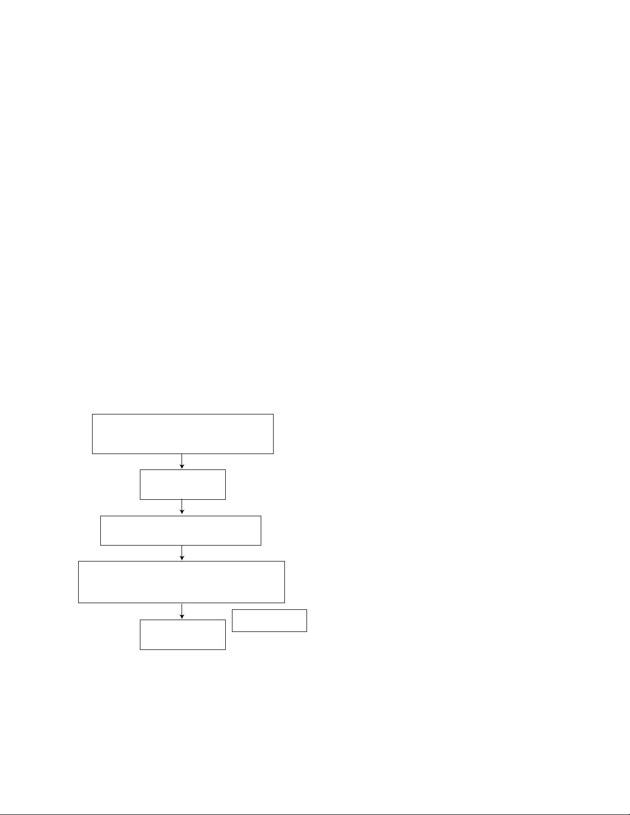
(1) Indication of the C1 error
While pressing both the POWER key
and BACK SKIP key on the main unit,
turn on the primary power supply.
FL indication
CRC = 0
Press the CD OPEN/CLOSE key
and insert the test disk.
Press the CD PLAY key. The set starts
counting and the number of error correction
times is indicated every 10 seconds.
FL indication
CRC = ***
200 Hz or less
1-2
(2) Cancel of the C1 error indication
To cancel the C1 error indication, cut off the power supply.
Page 3

2) MD section
UX-A70MDR
(1) Setup of the TEST MODE 1
While pressing both the POWER
key and FORWARD SKIP key, turn
on the primary power supply.
FL indication
TEST MODE 1
Setup is complete.
(3) Adjustment of the playback laser power
Set up the TEST MODE 1.
Press the STOP key on
the remote controller.
(2) Initialization of the EEPROM
(The EEPROM can be initialized on the precondition that the
setup of the TEST MODE 1 is complete. After setup of the
TEST MODE 1, proceed to the following operations with the
remote controller*.)
* For EJECT operation, use the EJECT key on the main unit.
Initialization of the EEPROM
Press the OPEN/CLOSE
key on
Press the PLAY MODE key
on
Press the STOP key on
(4) Adjustment of the recording laser power
Set up the TEST MODE 1.
the main unit
the remote controller.
FL indication
TEST MODE 1
the remote controller.
Press the STOP key on
the remote controller.
Setup is complete.
Insert the laser power
meter sensor.
Press the "2" key on
the remote controller.
Set up the playback
laser power.
Increase the laser
power with the F.
SKIP key on the
remote controller.
Adjust the power to be 0.68 mW or
more. If the value exceeds 0.68 mW,
approximate it to 0.68 mW as
accurately as possible.
Press the STOP key on
the remote controller.
Press the MD EJECT
key on the main unit.
Decrease the laser
power with the B.
SKIP key on the
remote controller.
Insert the laser power
meter sensor.
Press the "4" key on
the remote controller.
Set up the recording
laser power.
Increase the laser
power with the F.
SKIP key on the
remote controller.
Adjust the power to be 6.23 mW or
more. If the value exceeds 6.23 mW,
approximate it to 0.68 mW as
accurately as possible.
Press the STOP key on
the remote controller.
Press the MD EJECT
key on the main unit.
Decrease the laser
power with the B.
SKIP key on the
remote controller.
Setup of the MD laser
power is complete.
Setup of the MD laser
power is complete.
1-3
Page 4

UX-A70MDR
(5) Adjustment of the disk
Set up the TEST MODE 1.
Insert the
premastered disk.
Reading of TOC ends.
Press the MD PLAY
key on the remote
controller.
FL indication
ON TUNING
Automatic adjustment starts.
Adjustment OK?
YES
FL indication
OK TUNING
NO
Press the STOP
key on the remote
controller.
* If an error indication of "ERR:07"
appears at the first adjustment, try
to make a fresh start of the same
adjustment.
FL indication
NG ERR: XX
XX: Refer to the NG judgment code table.
Press the STOP key on
the remote controller.
Press the EJECT key
on the main unit.
Insert a recordable
disk.
Press the MD PLAY key
on the remote controller.
FL indication
ON TUNING
Automatic adjustment starts.
Adjustment OK?
YES
NO
NG Judgment Code Table
Code
00 Automatic adjustment is incomplete.
01 Rest switch detection
02 Focus-on
03 EF balance, tracking offset adjustment (Pit area)
04 ABCD level (I-V resistance) adjustment (Pit area)
05 Focus servo AGC (Pit area)
06 Tracking servo AGC (Pit area)
07 Focus bias adjustment (Pit area)
08 EF balance, tracking offset adjustment (GRV area)
09 ABCD level (I-V resistance) adjustment (GRV area)
0A Focus servo AGC (GRV area)
0B Tracking servo AGC (GRV area)
0C Focus bias adjustment (GRV area)
0D Room temperature measurement
0E Write in EEPROM
10 (Focus, TRK, SLED) AGC data read time-out
20 Pit area spindle lock
30 Groove area spindle lock
XX Automatic adjustment is complete.
NG item in adjustment
FL indication
ON TUNING
Press the STOP key on
the remote controller.
Press the MD EJECT
key on the main unit.
1-4
FL indication
NG ERR: XX
Refer to the NG judgment code table.
Automatic adjustment
ends.
Press the POWER key on the
main unit or remote controller.
Cut off the power supply after
cancelling the TEST MODE.
Page 5

UX-A70MDR
For investigating the mode in which an error
occurred during the disk adjustment, freeze the
set in the mode by pressing the proper key
(refer to the table on the right) on the remote
controller before cancelling the TEST MODE 1.
(6) Setup of the TEST MODE 2
While pressing both the POWER key and
FORWARD STOP key on the main unit,
turn on the primary power supply.
FL indication
TEST MODE 2
While pressing the STOP key on the main
unit, press the FM/AM key on the main
unit double. The TEST MODE 2 is set up.
Key to press Mode
SLEEP key (Remote controller)
"6" key (Remote controller)
"7" key (Remote controller)
"8" key (Remote controller)
"9" key (Remote controller)
STOP key (Remote controller)
EJECT key (Main unit)
FOCUS SEARCH
PIT ROUGH SERVO
GROOVE ROUGH SERVO
TRACKING ON
TRACKING OFF
STOP
EJECT
FL indication
TEST MODE 2
Setup is complete.
(7) Indication of variation in the pickup adjustment value
Set up the TEST MODE 2.
Press the MD OPEN/CLOSE key
and insert the MD test disk.
Press the "6" key on the
remote controller.
FL indication*
XXXXX - XXXX
* Each time the
"6" key on the
remote
controller is
pressed, the
indication
changes from
ASG to TRG,
from TRG to
TRB, and so
on as shown
in the figure.
ASG
TRG
TRB
FOB
FGR
FEXP
FGC
FG
TGR
TEXP
TGC
TG
-1
-2
:
-128
127
126
:
1
0
(8) Indication of the C1 error
Set up the TEST MODE 2.
Press the MD OPEN/CLOSE key
and insert the MD test disk.
Press the "8" key on the remote controller. Counting of
number of C1 errors starts and it continues until it
counts up the maximum number of C1 errors with
indication (maximum number of error indication is 432).
FL indication*
200 Hz or less
X X Y Y Z Z
(9) Cancel of the TEST MODE
(The cancel operation is common to the TEST
MODE 1 and 2.)
Cut off the primary power supply to cancel the
TEST MODE.
1-5
Page 6

UX-A70MDR
VICTOR COMPANY OF JAPAN, LIMITED
AUDIO & COMMUNICATION BUSINESS DIVISION
PERSONAL & MOBILE NETWORK BUSINESS UNIT. 10-1,1chome,Ohwatari-machi,Maebashi-city,371-8543,Japan
(No.20907B)
200103
 Loading...