

Page 1
DOME TYPE CAMERA
DOME-FARBKAMERA
CAMERA DE TYPE DOME
CÁMARA TIPO CÚPULA
TELECAMERA A DUOMO
TK-C676
ENGLISH
DEUTSCH
FRANÇAIS
INSTRUCTIONS
ESPAÑOL
ITALIANO
Page 2

IMPORTANT SAFEGUARDS
1. Read all of these instructions.
2. Save these instructions for later use.
3. All warnings on the product and in the operating instructions should be adhered to.
4. Unplug this appliance system from the wall outlet before cleaning. Do not use liquid cleaners or aerosol cleaners. Use
a damp cloth for cleaning.
5. Do not use attachments not recommended by the appliance manufacturer as they may cause hazards.
6. Do not use this appliance near water – for example, near a bathtub, washbowl, kitchen sink, or laundry tub, in a wet
basement, or near a swimming pool, etc.
7. Do not place this appliance on an unstable cart, stand, or table. The appliance may fall,
causing serious injury to a child or adult, and serious damage to the appliance.
Use only with a cart or stand recommended by the manufacturer, or sold with the appliance.
Wall or shelf mounting should follow the manufacturer’s instructions, and should use a
mounting kit approved by the manufacturer.
An appliance and cart combination should be moved with care. Quick stops, excessive
force, and uneven surfaces may cause the appliance and cart combination to overturn.
8. Slots and openings in the cabinet and the back or bottom are provided for ventilation, and to
insure reliable operation of the appliance and to protect it from overheating, these openings
must not be blocked or covered. The openings should never be blocked by placing the appliance on a bed, sofa, rug,
or other similar surface. This appliance should never be placed near or over a radiator or heat register. This appliance
should not be placed in a built-in installation such as a bookcase unless proper ventilation is provided.
9. This appliance should be operated only from the type of power source indicated on the marking label. If you are not
sure of the type of power supplied to your home, consult your dealer or local power company. For appliance designed
to operate from battery power, refer to the operating instructions.
10. This appliance system is equipped with a 3-wire grounding type plug (a plug having a third (grounding) pin). This plug
will only fit into a grounding-type power outlet. This is a safety feature. If you are unable to insert the plug into the
outlet, contact your electrician to replace your obsolete outlet. Do not defeat the safety purpose of the grounding plug.
11. For added protection for this product during a lightning storm, or when it is left unattended and unused for long
periods of time, unplug it form the wall outlet and disconnect the antenna or cable system. This will prevent damage to
the product due to lightning and power-line surges.
12. Do not allow anything to rest on the power cord. Do not locate this appliance where the cord will be abused by
persons walking on it.
13. Follow all warnings and instructions marked on the appliance.
14. Do not overload wall outlets and extension cords as this can result in fire or electric shock.
15. Never push objects of any kind into this appliance through cabinet slots as they may touch dangerous voltage points
or short out parts that could result in a fire or electric shock. Never spill liquid of any kind on the appliance.
16. Do not attempt to service this appliance yourself as opening or removing covers may expose you to dangerous
voltage or other hazards. Refer all servicing to qualified service personnel.
17. Unplug this appliance from the wall outlet and refer servicing to qualified service personnel under the following conditions:
a. When the power cord or plug is damaged or frayed.
b. If liquid has been spilled into the appliance.
c. If the appliance has been exposed to rain or water.
d. If the appliance does not operate normally by following the operating instructions. Adjust only those controls that
are covered by the operating instructions as improper adjustment of other controls may result in damage and will
often require extensive work by a qualified technician to restore the appliance to normal operation.
e. If the appliance has been dropped or the cabinet has been damaged.
f. When the appliance exhibits a distinct change in performance – this indicates a need for service.
18. When replacement parts are required, be sure the service technician has used replacement parts specified by the
manufacturer that have the same characteristics as the original part. Unauthorized substitutions may result in fire,
electric shock, or other hazards.
19. Upon completion of any service or repairs to this appliance, ask the service technician to perform routine safety
checks to determine that the appliance is in safe operating condition.
PORTABLE CART WARNING
(symbol provided by RETAC)
S3126A
E-2
Page 3

WARNING:
TO REDUCE THE RISK OF FIRE OR
ELECTRIC SHOCK, DO NOT EXPOSE THIS
APPLIANCE TO RAIN OR MOISTURE.
Thank you for purchsing this product.
(These instructions are for TK-C676E)
Before beginning to operate this unit, please read the instruction manual carefully in order to make sure that the best possible
performance is obtained.
Contents
Introduction
Features ............................................................................................................................................................................. 4
Provided Accessories ......................................................................................................................................................... 4
Safety Precautions ............................................................................................................................................................. 4
Precautions for Correct Operation ...................................................................................................................................... 5
Controls, Connectors and Indicators .................................................................................................................................. 6
Connections & Installation
A Multi-Drop Communication System ................................................................................................................................ 8
Point-to-Point Communication System ............................................................................................................................. 10
Switch Settings ................................................................................................................................................................. 12
Cable Connections ........................................................................................................................................................... 14
Attaching the Ceiling Mount ............................................................................................................................................. 16
Attaching the Camera ....................................................................................................................................................... 16
ENGLISH
Setting Up the Camera using an RM-P2580
Setup Procedure .............................................................................................................................................................. 18
Menu Screen Flow............................................................................................................................................................ 19
CAMERA FUNCTION Screen .......................................................................................................................................... 20
CAMERA TITLE/ALARM Screen ...................................................................................................................................... 21
CAMERA VIDEO ADJUSTMENT Screen ........................................................................................................................ 23
CAMERA ALC/ExDR Screen ........................................................................................................................................... 23
HOME MOTION DETECT Screen.................................................................................................................................... 26
AUTO PAN/PATROL/TRACE Screen................................................................................................................................ 27
POSITION FUNCTION SET Screen ................................................................................................................................ 28
FACTORY SETTINGS Screen .......................................................................................................................................... 28
PRIVATE MASK Setup ..................................................................................................................................................... 29
CAMERA TITLE Setup ..................................................................................................................................................... 30
AREA TITLE Setup ........................................................................................................................................................... 31
ALARM TITLE Setup ........................................................................................................................................................ 32
HOME MOTION DETECT Setup...................................................................................................................................... 33
AUTO PAN Setup ............................................................................................................................................................. 34
AUTO PATROL Setup ....................................................................................................................................................... 35
AUTO TRACE Setup ........................................................................................................................................................ 36
POSITION TITLE Setup ................................................................................................................................................... 37
Other
Attaching a Ceiling Flush Mount Bracket (Optional WB-S575) ......................................................................................... 38
Removing a Ceiling Flush Mount Bracket (Optional WB-S575) ....................................................................................... 40
Troubleshooting ................................................................................................................................................................ 41
Specifications ................................................................................................................................................................... 42
E-3
Page 4
Introduction
Features
DSP with a wide dynamic range
Even objects that have a large difference in brightness can be monitored clearly.
Day/night surveillance
When the light is low, the camera pictures can be switched automatically to black and white pictures.
The camera is also compatible with IR illumination (wavelength 850 nm to 880 nm).
Private masking facility
When the camera target area contains an area that is required to be hidden the camera can be set accordingly in order to mask it.
Simplified waterproof design
The simplified waterproof design (IEC529) of the camera allows it to be installed in many locations, including under eaves,
provided that it is not subjected to direct water splash. (However, note that the camera cannot be used outdoors.)
Optical + electronic zooming
The 27X optical zoom lens and 10X electronic zoom circuitry allows the camera to be used even in surveillance situations in
which the object is very small.
High-sensitivity CCD and bright zoom lens
The CCD features an improved sensitivity of nearly 70% over the previous model and the zoom lens has a large aperture ratio of
f1.4 (at WIDE end). These features provide the camera with a high sensitivity of 0.5 lx in the color mode (25% output, AGC 20 dB,
WIDE end, electronic sense up x2).
High-speed pan/tilt table
The high-speed rotating table with a horizontal panning speed of 300°/sec. and a vertical tilting speed of 180°/sec. makes it
possible to recall a preset position quickly.
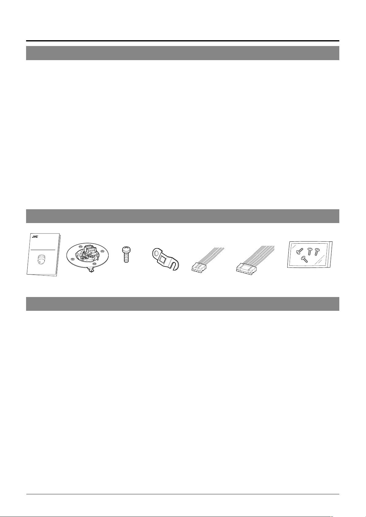
Provided Accessories
DOME TYPE CAMERA
DOME-FARBKAMERA
CAMERA DE TYPE DOME
CÁMARA TIPO CÚPULA
TELECAMERA A DUOMO
INSTRUCTIONS
TK-C676
LWT0000-000
Instructions Ceiling mount
Screw
(M3 × 12 mm)
For cable plate
Cable plate 4P Alarm cable
6P Alarm cable
Screws (M 4 x 12 mm)
For the ceiling flush
mount bracket
Safety Precautions
WARNING
• Install the unit on a strong and stable surface.
This unit has been designed to revolve at high speed. Due to its weight (about 2.4 kg) and the vibrations it may be subjected to, the
camera must be mounted to a sturdy and stable material. If the ceiling material lacks strength, for example it is made of a decorative
laminated material or plasterboard, then the mount should be reinforced using materials such as veneered plywood. If such reinforcement is inadequate images may fluctuate due to vibration or, in the worst case, the camera may fall and cause a serious accident
should there be anyone below it.
• For installation, use the provided ceiling mount and the optional flush mounted ceiling bracket, which is sold separately.
When installing this device the provided ceiling mount and the optional flush mounted ceiling bracket, which is sold separately
should be used. Also be sure to connect the drop prevention wire and tighten all screws and nuts firmly.
• Power the unit with the rated power voltage.
The power rating for this unit is 24 V AC, 50 Hz/60 Hz. If a power above this rating is supplied, a malfunction will occur or, in the
worst case, smoke or fire may be produced.
• This unit offers a certain degree of protection against any damage either to itself or to its connection cable that might result from
indirect lightning strikes, but it is not capable of preventing all damage by lightning strikes. For example it is not protected against
a direct lightning strike. If lightning damage can be expected in the place where the unit is installed, be sure to take countermeasures by adding an arrester to the connection cable, etc.
CAUTION
• Installation of this unit requires special skills. Please be sure to consult your dealer about installation procedures.
If the mounting screws or nuts are not tightened sufficiently, the camera may fall from its installation location. Be sure to tighten the
mounting nuts firmly to prevent this happening.
• Inspect the unit periodically.
Check periodically for any deterioration of the mount sections or loosening of screws due to vibration and ensure that there is no
likelihood of the unit dropping.
E-4
Page 5

Precautions for Correct Operation
Note on consumable parts
The following parts are consumable and should be replaced
after a certain number of hours or a count of operations.
The service lives given below are only typical values. They
may vary depending on the operating environment and
conditions.
Note that the replacement of consumable parts is chargeable even when they are replaced before the termination of
the warranty period.
• Zoom lens assembly
Zooming operation : 2 million times
Focusing operation : 4 million times
• Slip rings : 5 million operations
• Cooling fan : Approx. 30,000 hours
• Alarm output 1 relay : 200,000 times of operation
Note on auto focusing
Although this unit incorporates a one-push auto-focusing
system and EASY AF functions, auto-focusing may sometimes be impossible depending on the object and camera
setup. In this case, adjust the focusing manually.
Objects and images with which auto focusing may be difficult:
• When the image brightness is extremely high.
• When the image brightness is extremely low.
• When the image brightness varies continuously (for ex-
ample when the object is a flashing light).
• When the image contrast (difference between bright and
dark) is very poor.
• When the image does not contain a vertical contour
component.
• When vertical stripe patterns recur on the screen.
Camera setups with which auto focusing may be difficult:
• When the AGC is activated and the image is coarse.
• When SENSE UP is activated and the image contains
only little motion.
• When electronic zooming is activated and the image
does not contain a large enough contour component.
● To save energy, turn the system off whenever it is not in use.
● This camera has been designed for indoor use. It cannot be used out-
doors.
● This camera has been designed to be hung from a ceiling, do not install
it in an upright position on a surface or at an angle, as this may cause a
malfunction or a noticeable shortening of its service life.
● Do not install or use the camera in the following locations.
• In a place exposed to rain or water. (The waterproof characteristics of
the camera are equivalent to IEC 529.)
• In a place containing vapor or oil soot, for example in a kitchen.
• In a place outside the operating temperature range (-10°C to 50°C).
• Near a source of strong radio waves or magnetism, radiation or X-rays.
• In a place subject to vibrations.
• In a place with excessive dust.
● Insufficient ventilation of the camera may cause a malfunction. Be careful not to block ventilation to the camera.
This unit radiates heat from the panel surfaces (top panel and side
panels). Do not install it in a place where a heat pool may form, such as
near a wall.
● Do not install the camera in a place exposed to cold air, for example
near to the air outlet of an air conditioner. Otherwise, moisture may
become condensed inside the dome cover.
● Do not point the lens at a strong light source, for example the sun, doing
so may cause the camera to malfunction.
● The camera incorporates an AGC circuit. As a result, when it is used
under low light conditions the camera gain may increase automatically.
This makes the picture appear uneven , however this is not a malfunction
● When equipment that generates strong magnetism such as a transceiver
is used near to the unit while the AGC circuit is ON, beat noise, etc may
interfere with the picture. If a transceiver or similar equipment is used
keep it a distance of at least 3 meters from this unit.
● In auto iris mode, when the AGC circuit is ON, varying the iris with the
iris control button may not change the picture brightness. This is due to
the automatic gain boost by the AGC circuit. In this case, set AGC to
OFF or use the manual iris mode.
● In auto iris mode, the iris control button may not function under certain
brightness conditions (i.e. when a sufficient amount of light cannot be
obtained). In this case, set the iris mode to manual.
● When the camera is used in ATW (Auto White balance) mode, the
colors captured by the camera may differ from the actual colors being
shot due to the mechanics of the auto-tracking operation within the
white balance circuit. However, this is not a malfunction.
● If a very bright object (such as a lamp) is being monitored, the picture
may contain vertical lines (smear) above and below the bright object in
the picture. This is a phenomenon normal to a solid-state image pickup
devices (CCD) and is not a malfunction.
● The electronic shutter speed of the camera has been set to 1/50 second at the factory. If the camera is used under a fluorescent light source
in an area with a local power frequency of 60 Hz, change the shutter
speed to 1/120 second using the remote control unit. (Note that the
sensitivity will deteriorate slightly.)
However, when the ExDR function is ON, the flicker may not disappear.
● When the camera is used to monitor the same position over many
hours ( e.g. continuously for 24 hours a day) the contact resistance of
the panning mechanism may increase. This may cause the picture to
be affected by noise interference or the remote control operation becoming unstable. To prevent this happening, once a week, turn the system off and on in order to initialize the camera and to clean the contacts.
● Do not touch the lens on the dome cover directly by hand. Contamination of the cover will lead to deterioration of the picture quality.
● Since the dome cover has a semispherical shape, the picture is distorted
at the edges of the semisphere. When the camera is pointed for horizontal-direction shooting by tilting, it shoots the edge of the hemisphere, so
that the picture may be distorted or out of focus.
● When an object is located near a light source or contains a large difference in brightness, a ghost may interfere with the picture. This phenomenon is due to the characteristics of the dome cover and the built-in lens
and is not a malfunction.
● Observe the following points when carrying out maintenance of the
camera.
• Turn the system off before proceeding.
• Clean the dome cover using a lens cleaning cloth (or tissue).
The dome cover may become stained in a very short period in certain
operating environments. If the dome cover lens becomes excessively contaminated, clean it with a lens cleaning cloth (or tissue)
moistened with a solution of neutral detergent in water.
Zooming
When zooming is stopped near the TELE end during manual operation or by selecting a preset position, focusing may deviate
slightly. In addition, the manual zooming operation may not always
be smooth.
These phenomena are due to the characteristics of the built-in
lens and are not malfunctions.
Preset positions
• The zooming position of the camera can be set to a total of 100
preset positions, including the home position.
• The electronic zoom can be preset up to x2.
However, if the electronic zoom menu on the screen is set to
OFF even presetting the electronic zooming to x2 , the camera
itself moves to the preset position without the electronic zooming being activated.
• It is not permitted to preset the electronic zoom to a larger ratio
than x2. The message “INVALID POSITION (D.ZOOM)” will
appear on the screen if a larger ratio than x2 is set.
• The TILT position can be set and operated only between 0° to
90° even when the item “FLIP” is set to DIGITAL.
(A TILT position between 91° and 180° cannot be set or oper-
ated. The message “INVALID POSITION (TILT) will appear on
the screen if a larger TILT position than 90° is set.)
ENGLISH
E-5
Page 6
Introduction
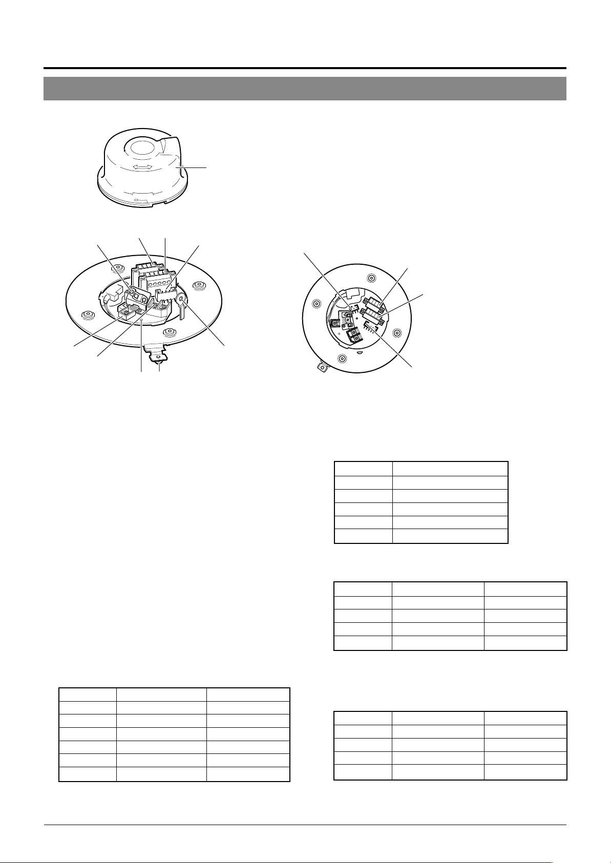
Controls, Connectors and Indicators
Ceiling Mount
0
Cover
96
1
2
87
9
5
43
■ Camera body
Pin 1 of alarm output terminal
(CN24)
Pin 1 of CONTROL terminal
8
(CN22)
7
Pin 1 of alarm input terminal
6
(CN26)
Pin 1 of ALARM I/O terminal
(CN23)
(Connector side)
[VIDEO OUT] Coaxial Cable Connectors
1
Output connector of a composite video signal (1 V(p-p))
with an output impedance of 75 Ω, to be connected to a
switcher, etc.
[AC ` 24V INPUT] Connector
2
Connect to a 24 V AC power supply.
Cover Position Alignment Mark
3
When attaching the cover, use this mark to align its final
position correctly.
Locking Screw
4
Tighten this screw to fasten the camera clamping bracket
.
*
Safety Wire Hole
5
To prepare for possible dropping of the camera, pass the
wire from the ceiling slab or channel through this hole.
Alarm Input Terminals (CN26)
6
Input terminals for Alarm 2, Alarm 3 and Alarm 4.
Connect the provided cables to these terminals.
P. 1 5
☞
Pin No. Signal Name Color of Cable
1 Alarm input 2 Brown
2 GND Red
3 Alarm input 3 Orange
4 GND Yellow
5 Alarm input 4 Violet
6 GND Gray
(Terminal Pin Layout)
[ALARM I/O] Input/Output Terminals (CN23)
7
Terminals for Alarm input 1 and Alarm output 1.
P. 1 5
☞
Pin No. Signal Name
1 Alarm output 1
2 Alarm output 1 (COM)
3 Alarm output 1
4 Alarm input 1
5 GND
[CONTROL] Terminals (CN22)
8
Connect to a RM-P2580 remote control unit.
Pin No. Signal Name Mark
1 TX + A
2 TX – B
3 RX + C
4 RX – D
Alarm Output Terminals (CN24)
9
Output terminals for Alarm 2 and Alarm 3.
Connect the provided cables to these terminals.
P. 1 5
☞
Pin No. Signal Name Color of Cable
1 Alarm output 2 + Red
2 Alarm output 2 – White
3 Alarm output 3 + Orange
4 Alarm output 3 – Gray
(N.OPEN)
(N.CLOSE)
E-6
Page 7
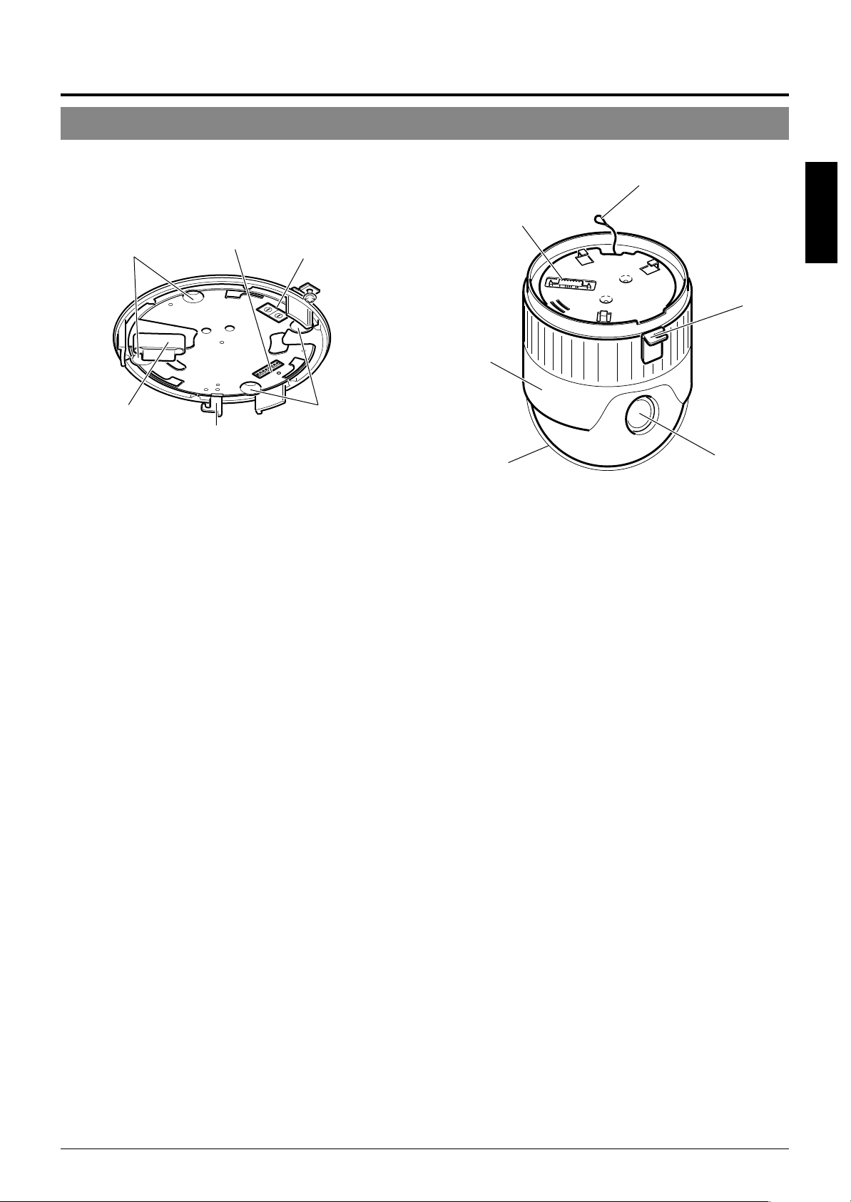
&
#
!
%
$
#
@
(Setting switch side)
Cover
0
For protection against water drips. Slit the rubber cap on
this cover and pass the cable through the slits.
P. 1 4
☞
Camera Connector (Female)
!
Connect to ^, the Male Connector on the camera.
Drop Prevention Hook
@
Attach the Drop Prevention Wire & to this hook to prevent
the camera from falling.
Clamping Holes (x 4)
#
Attach the camera to a ceiling or to a Ceiling Flush Mount
Bracket (optionally available) using these holes.
[MACHINE ID] Switch
$
When an RS-485 communication system is used, for example when using the camera in a system controlled by
an RM-P2580, set the camera IDs individually for each
camera.
P. 1 3
☞
^
⁄
)
Connector (Male)
^
Connect to !, the Female Camera Connector on the Ceil-
ing Mount.
Drop Prevention Wire
&
Attach this wire to the Drop Prevention Hook @ on the
Ceiling Mount.
Camera Clamping Bracket
*
In order to clamp the camera onto the Ceiling Mount, insert and tighten the Locking Screw
Lens
(
The lens cannot be replaced.
Dome Cover
)
The dome cover is fragile. Take care when handling it.
Camera Body Cover
⁄
Do not remove the camera body cover while the camera is
installed on a ceiling. Doing so will cause the dome cover
to fall down.
(
into this bracket.
4
ENGLISH
*
Setting Switches
%
Use these to set the PROTOCOL, etc.
P. 1 2
☞
E-7
Page 8

Connections & Installation
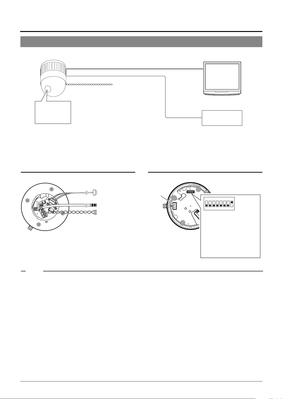
A Multi-Drop Communication System
䡵 A system that employs the RM-P2580 as the controller
The following figure shows a system that can accommodate up to eight cameras. (64 positions can be preset per camera.)
TK-C676
Camera 1
MACHINE ID: 01
Switch 8: OFF
(RX TERM)
TK-C676
Camera 2
MACHINE ID: 02
Switch 8: OFF
(RX TERM)
TK-C676
Camera 8
MACHINE ID: 08
Switch 8: ON
(RX TERM)
Control signal cable
Coaxial cable
Remote control unit
RM-P2580
AC 24 V
power supply
AC 24 V
power supply
AC 24 V
power supply
CAMERA
Observe the following points when connecting components together:
• Turn all the components off before proceeding.
• Read the instruction manuals of all components before pro-
ceeding.
• For the types and lengths of connection cables, see “Cable
Connections” on page 14.
• Do not connect the control signal cables in a loop.
TO
Monitor
Cable connections
☞
P. 1 4
(Terminal side of Ceiling Mount)
Control signal cable
Coaxial cable
Power cable
Connection of the control signal cable
(A twisted pair cable is recommended.)
Camera 1
CONTROL terminals
TX +A
TX –B
RX +C
RX –D
Camera 2
CONTROL
terminals
+
TX
A
TX –B
RX +C
RX –D
Camera 3
CONTROL
terminals
TX +A
TX –B
RX +C
RX –D
RM-P2580
terminal
+
RX
A
–
RX
B
TX +C
TX –D
Each terminal on the camera and the RMP2580 is marked A䡬, B䡬, C䡬 or D䡬. In order
to facilitate understanding and to avoid
connection mistakes, it is recommended
to connect the terminals carrying the
same marks.
To the TO CAMERA connector of the
RM-P2580 and to the next camera
To the CAMERA INPUT connector
of the RM-P2580
To AC 24V power supply
MONITOR
OUTPUT 1
Switch settings
☞
P. 1 2
(Setting switches are on the side of the Ceiling Mount)
Machine ID
3
2
4
1
5
0
6
9
Figure of 1
7
8
3
2
4
1
5
0
6
Figure of 10
9
7
8
Set it to the same number as the
VIDEO INPUT terminal of the RMP2580.
(Example) Camera 1:
Set the figure of 10 to “0” and
figure of 1 to “1”.
Camera 1 monitor display
at power ON
LPROCESS<<>> I INTIA
:--I--PAN
:--I--TILT
DUPLEX I D- 01ROT>P COOL
Duplex display ID No. display
(ID check procedure
☞
P. 13)
1234678
5
F
F
O
Switch 1
Switch 2
:
Invalid (Set to OFF.)
:
Switch 4 : ON
Switch 5 : OFF
Switch 7 :
Switch 8 :
Invalid (Set to OFF.)
Set to ON only for the
camera connected at
the end of the control
signal cable.
Set to OFF for all
other cameras.
E-8
Page 9

A system that does not employ the RM-P2580 as the controller
MEMO
Be sure to terminate the control signal cable at both ends. The cables (length of stub) connecting pieces of non-terminated
equipment (cameras or controllers) must be as short as possible. If the length of stub is too long, control precision may suffer.
● When the controller is not located at the end of a system.
(An AC 24V power source must be supplied to each camera)
CONTROL Cable
ENGLISH
CAM1 CAM2
PROTOCOL(1) : ON
MACHINE ID : 01
RX TERM : ON
PROTOCOL(1) : ON
MACHINE ID : 02
RX TERM : OFF
• Set the TERM switches of the cameras at each end
(CAM1 and CAM32) to ON, and the TERM switches of
Length of stub
CONTROLLER*
VIDEO
SWITCHER, etc.
the other cameras to OFF.
• Do not terminate at the controller.
● When the controller is located at the end of a system.
(An AC 24V power source must be supplied to each camera)
CONTROL Cable
CAM1 CAM2
Length of stub
Length of stub
CAM31 CAM32
PROTOCOL(1) : ON
MACHINE ID : 31
RX TERM : OFF
CAM32
Length of stub
PROTOCOL(1) : ON
MACHINE ID : 32
RX TERM : ON
Length of stub
Terminate it
with 110 Ω.
PROTOCOL(1) : ON
MACHINE ID : 01
RX TERM : ON
PROTOCOL(1) : ON
MACHINE ID : 02
RX TERM : OFF
• Set the TERM switch of CAM1 to ON, and terminate at the con-
troller with a resistance of 110 Ω.
Set the TERM switches of the other cameras to OFF.
CONTROLLER*
PROTOCOL(1) : ON
MACHINE ID : 32
RX TERM : OFF
VIDEO
SWITCHER, etc.
E-9
Page 10
Connections & Installation
Point-to-Point Communication System
The following illustration shows a system in which a remote control unit (or a similar piece of equipment) controls a single camera.
Video out
Control signal cable
AC 24 V
power supply
Monitor
Switch 4 : OFF
(Point to Point)
Switch 8 : ON
(Terminated 110Ω)
Observe the following points when connecting components together:
• Turn all the components off before proceeding.
• Read the instruction manuals of all components before proceeding.
Controller
Cable connections
(Terminal side of the Ceiling Mount)
P. 1 4
☞
Control signal cable
To controller
Coaxial cable
Power cable
To monitor
To the AC 24V power supply
Switch settings
(Setting switches are on the side of the Ceiling Mount)
Setting not
Setting not
required
required
P. 12
☞
123
4
678
5
F
F
O
Switch 1 : OFF
Switch 2 : OFF
Switch 4 : OFF
Switch 5 :
with the requirements of the controller
communication system.
Switch 7 : OFF
Switch 8 : ON
Configure in accordance
MEMO
If this camera or the cables connected to this camera are used in places subject to strong electromagnetic waves or other forms
of magnetism, for example near a radio or TV transmitter, a power transformer or an electric motor, the picture may suffer from
noise and colors may be affected.
An optionally available controller is required to use a TK-C676 camera. Please contact your local dealer or installer for more
information about these controllers.
E-10
Page 11
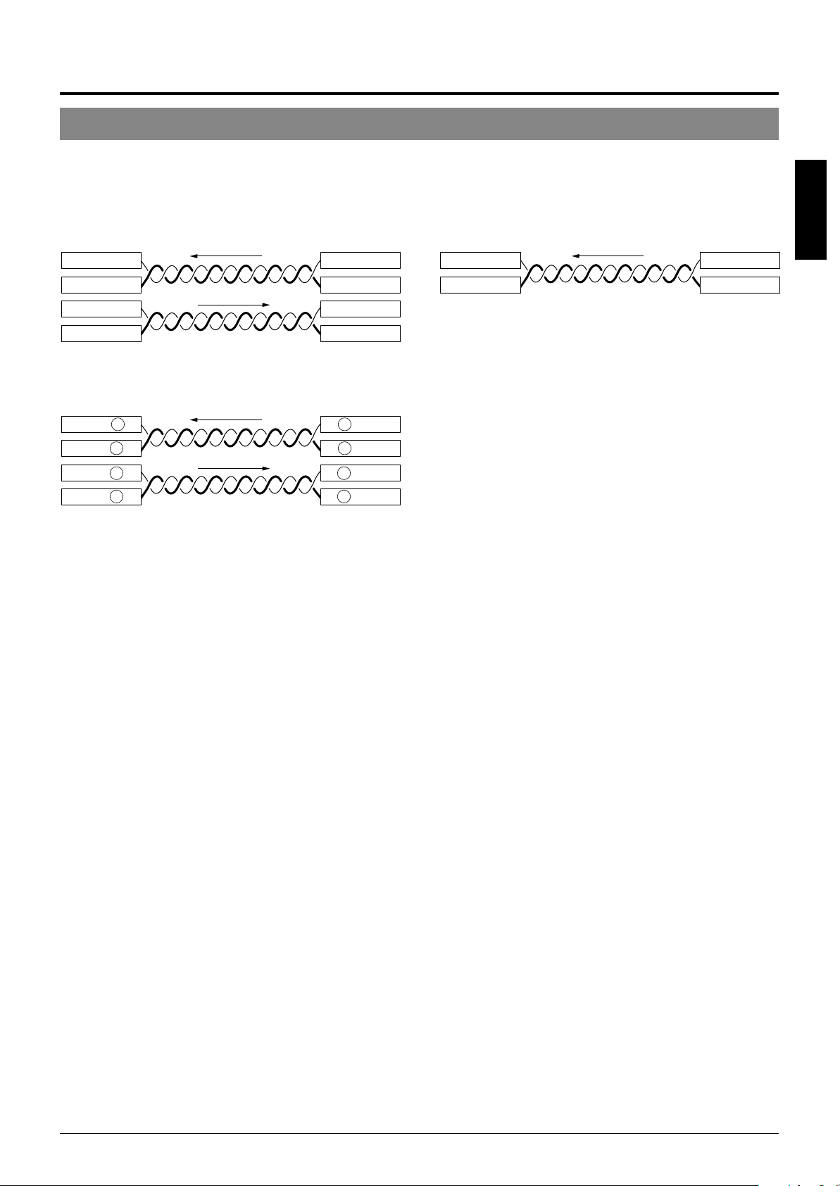
Use twisted-pair cables for the connections.
Camera Controller
RX+
RX–
TX+
TX–
●Duplex
When the camera is controlled using the full duplex protocol, set Switch 5 to OFF.
Camera Controller
RX+
RX–
TX+
TX–
Four wires must be connected.
For example (connection with an RM-P2580)
Camera RM-P2580
RX+ C
RX– D
TX+ A
TX– B
TX+
TX–
RX+
RX–
C TX+
D TX–
A RX+
B RX–
●Simplex
When the camera is controlled using the simplex transmission protocol, set Switch 5 to ON.
ENGLISH
Two wires must be connected.
E-11
Page 12
Connections & Installation
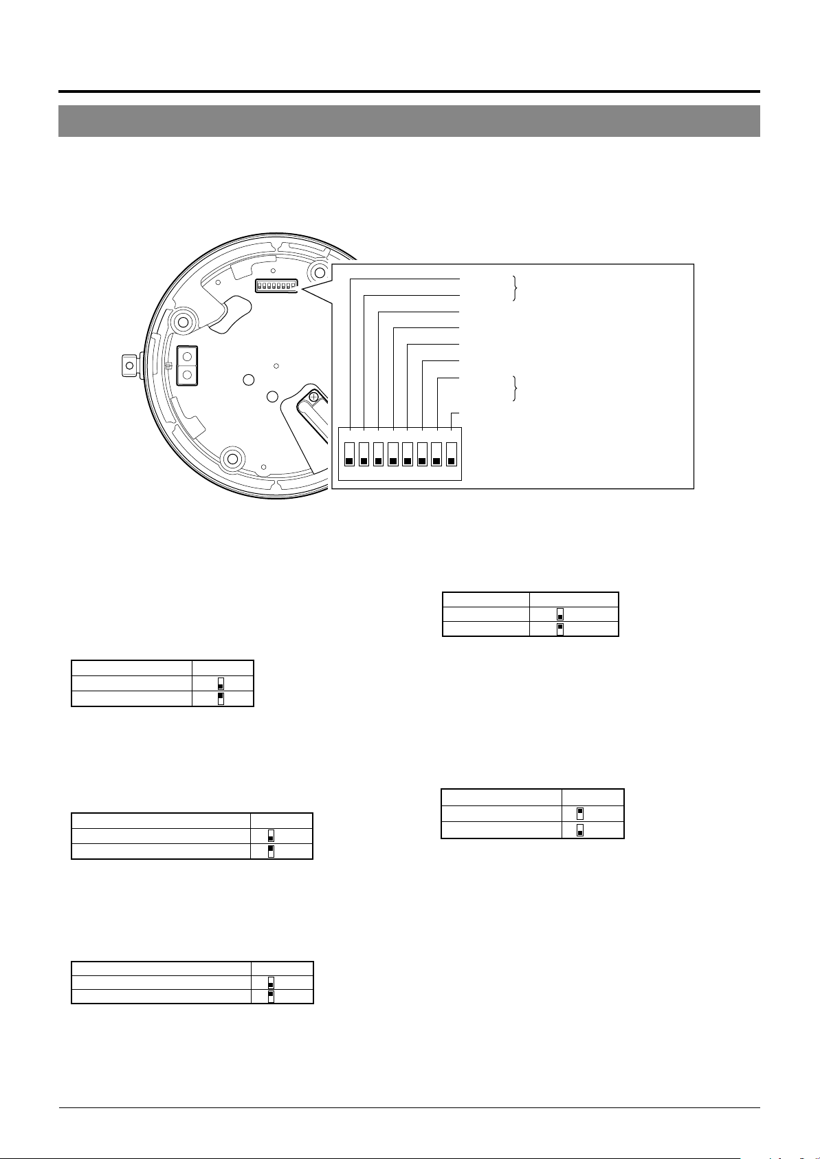
Switch Settings
Set the switches on the Ceiling Mount before installing the camera.
Settings vary according to configuration of the system used.
Setting switches
123
O
● Switches 1, 2
These switches must be set to OFF.
● DISP (Switch 3)
This switch selects whether “MANUAL” is displayed in the
screen when a remote control unit is used to move the camera manually (to a position other than those preset.).
Switch 3MANUAL
Displayed
Not displayed
(Initial setting: Displayed)
● PROTOCOL (1) (Switch 4)
Selects whether a single camera or multiple cameras are controlled in a system.
Set PROTOCOL(1) to Multi drop when connecting multiple
cameras in series.
Switch 4PROTOCOL (1)
Point to point OFF
Multi drop (when using the RM-P2580)
(Initial set: OFF)
ON
When set to Multi drop, be sure to set the Machine ID of each camera.
● PROTOCOL (2) (Switch 5)
Set this switch according to the communication protocol used
when controlling the cameras.
PROTOCOL (2)
Duplex (when using the RM-P2580)
Simplex ON
(Initial set: OFF)
Switch 5
OFF
Switch 1
Switch 2
Reserved
This switch must be set “OFF”
Switch 3 DISP
Switch 4 PROTOCOL(1)
Switch 5 PROTOCOL(2)
Switch 6 SYNC
Switch 7
Reserved
This switch must be set “OFF”
Switch 8 RX TERM
4
678
5
F
F
● SYNC (Switch 6)
When this switch is set to ON, the vertical sync of the camera
becomes locked to the frequency of the AC power line.
SYNC Switch 6
INT OFF
LL ON
(Initial set: OFF)
(LL mode : 50 Hz area only)
● Switch 7
This switch must be set to OFF.
● RX TERM (Switch 8)
This switch sets whether or not the section between control
signal terminals RX + and RX – is to be terminated (with a
resistance of 110 Ω.)
Switch 8RX Termination
Terminated (110 Ω)ON
Open OFF
(Initial setting: Terminated (110 Ω))
When the system in which this camera is used is a multidrop system (RS-485 system), set only the camera located
at the extreme end of the control signal cables to “Termi-
nated” and set the other cameras to “Open”.
E-12
Page 13
Setting switches
ENGLISH
3
2
4
1
5
0
6
7
4
5
6
7
Figure of 1
Figure of 10
9
8
3
2
1
0
9
8
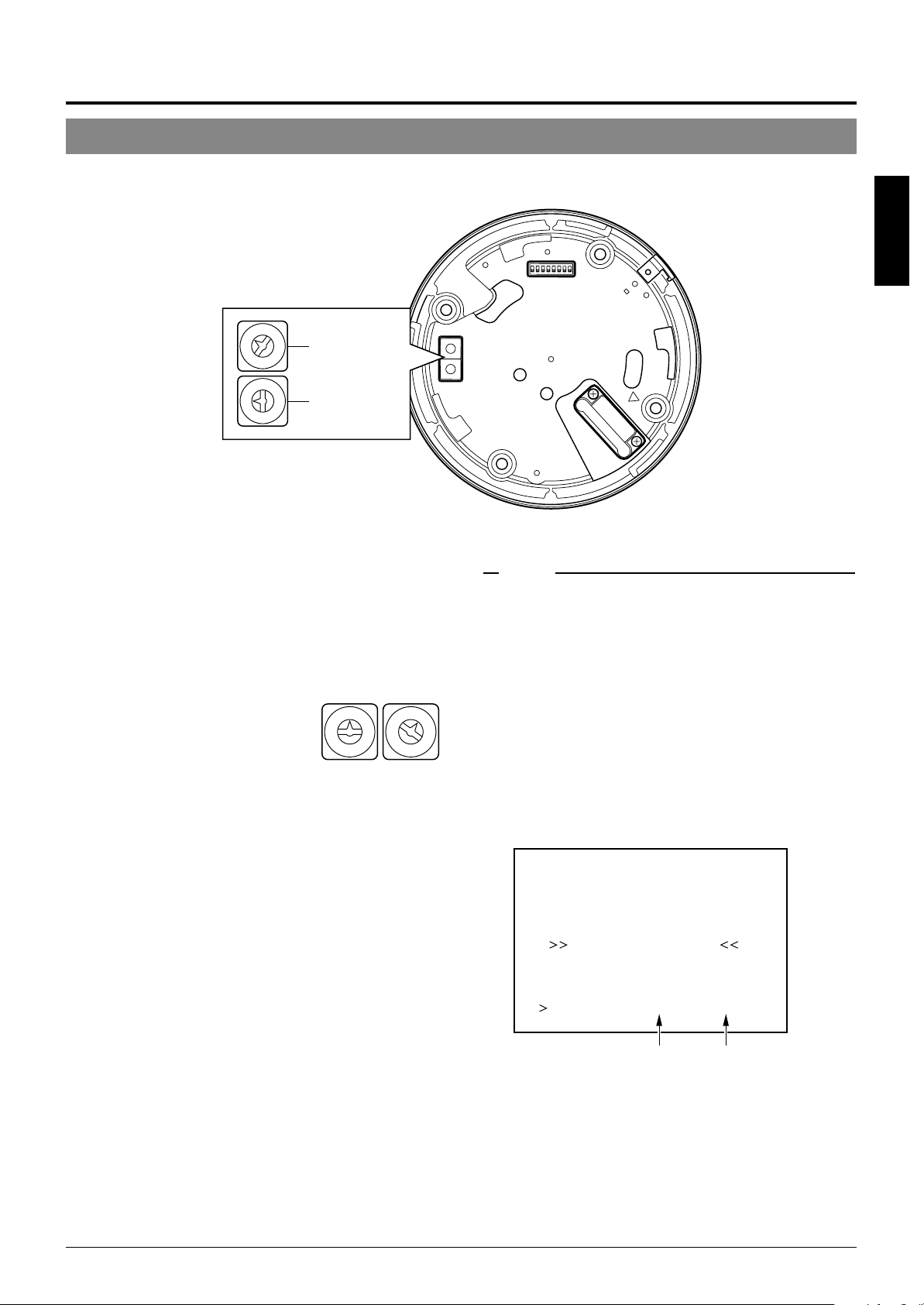
● Machine ID
When using a multi-drop system with a remote control unit
such as a RM-P2580, the machine IDs need to be set for
each camera.
Machine IDs are used to identify each of the multiple cameras connected to the RM-P2580. Set the machine IDs according to the corresponding VIDEO INPUT terminal numbers on the RM-P2580.
(Example)
The machine ID of the camera connected to VIDEO INPUT 1 should be
set to “0” “1” as shown on the right.
“0”“1”
0
1
9
8
7
6
5
Figure of 10 Figure of 1
9
2
8
3
7
4
MEMO
In a system using an RM-P2580, multiple cameras are connected
by a single set of control cables. An error in the switch setting of
even a single camera will make the entire system inoperable.
<Camera ID check procedure>
1.
0
1
2
3
4
6
5
Set the picture being monitored to that of the camera to
be checked.
2.
Turn the AC 24V power source of the camera OFF and
then ON again.
3.
The camera now performs the initialization operation and
the following display appears:
PROCESSIN TIIAL
I--PNA:-I--TI TL:--
UPLEX I D- 10PROT OCLD
“DUPLEX” should be displayed. “ID-□□” is displayed.
4.
Ensure that “DUPLEX” and “ID-□□” are displayed and
Ensure that the number
□□
is correct.
that the ID number is identical to the VIDEO INPUT terminal number on the RM-P2580.
5.
If the ID number is incorrect, reset it accordingly.
E-13
Page 14
Power cable
Control signal cable
To a remote controller
such as RM-P2580
To the monitor, etc.
To the AC 24 V
power supply
To a device with
alarm input
Coaxial cable
Alarm signal cable
Maximum cable length
100 m 260 m 410 m 500 m
Wire diameter (mm) 1.0 or more 1.6 or more 2.0 or more 2.6 or more
Connections & Installation
Cable Connections
Connect cables to the Ceiling Mount as described below.
1.
Make a 90 mm diameter hole in the ceiling.
Diameter 90 mm
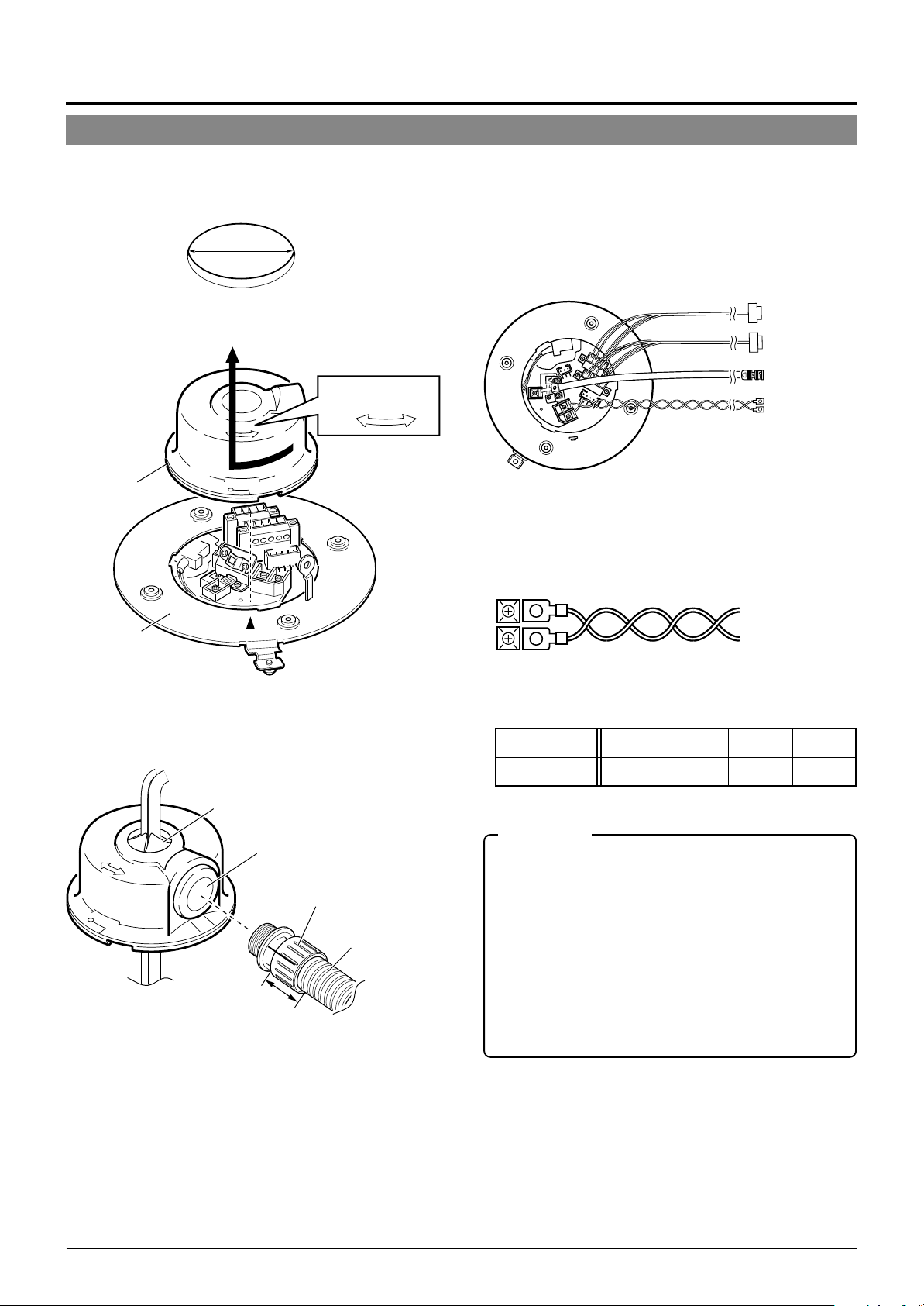
2.
Remove the cover from the Ceiling Mount.
RELEASE LOCK
Cover
4.
Connect the cables.
Connect the cables to the terminals on the Ceiling Mount.
The four connection cables should consist of a AC 24V
power cable, a coaxial cable, a control signal cable and
an alarm signal cable.
AC 24V power cable
This cable connects the AC 24V power supply to the AC
24V input connector. To prevent connection errors and
disconnections, the use of lug plate for connections to the
AC 24 V INPUT connector is recommended.
Ceiling mount
3.
Pass the cables through the cover.
Make slits in the rubber cap on the cover as shown in the
diagram below. Pull the cables through the hole in the
ceiling and pass the cables through the slits.
Cap (Top)
Cap (Side)
Connector
Maximum diameter 31 mm
Tube Maximum
diameter 22 mm
33 mm or less
Drip-proof pipe
The diameter of the cover hole without the cap is 20.5 mm.
When the camera is installed in a place where it may sometimes be exposed to water splashes, for example under
eaves, enclose cables in a drip-proof pipe.
(Be sure to use a water-drip pipe that complies with the
IP52. standard. The maximum diameter of the pipe connector is 31 mm.)
When distributing the cable from the side, use the WBS573 ceiling direct-mount bracket. In this case, the length
of the connector should be 33 mm or less, and the maximum diameter of the tube should be 22 mm or less.
E-14
When a 2-conductor VVF (Vinyl-insulated vinyl-sheath cable) is used, the maximum connection length is as shown
below. (These are merely the standard reference values.)
CAUTIONS
● When a thin cables are used the cable resistance increases.
As a result, when the power consumption of the unit is at its
maximum level (during the simultaneous operation of panning
and tilting) the effective voltage will drop.
If the voltage does drop while the camera is in use, performance can become unstable and preset positions may not be
reproduced accurately.
To prevent problems, use thicker cables that have a lower resistance or decrease the cable length by installing the power
supply unit close to the camera. Attempt to reduce drops in
voltage to less than 10% while the rated current level of the
camera is flowing through the cable.
● Do not connect an AC 24V cable directly to an AC 230 V outlet.
This will damage the unit.
Page 15
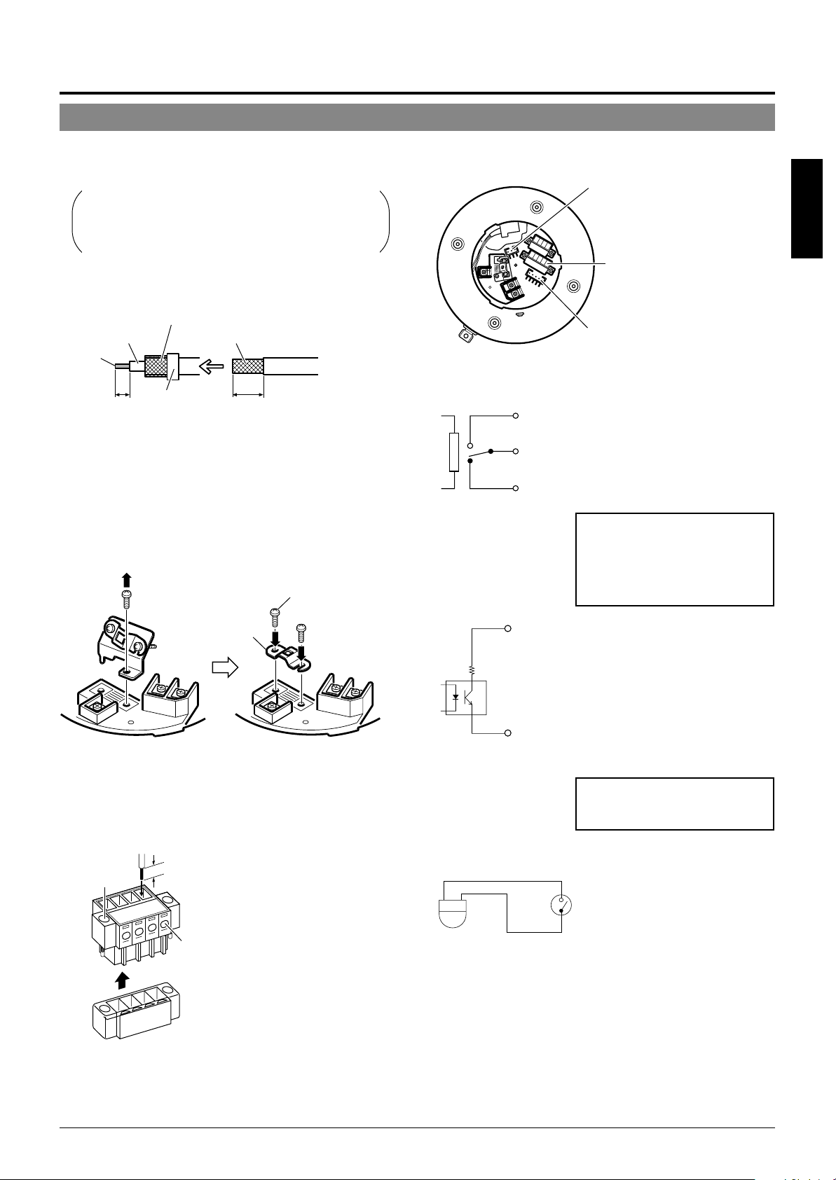
Coaxial cable
Connecting a RG-59 coaxial cable.
If a RG-11 coaxial cable is used it cannot be connected directly to the terminal board. To use such a
cable, connect a RG-59 cable to the camera and then
connect the RG-11 cable to the RG-59 cable.
Treat the extremity of the coaxial cable as shown below
before connecting it.
Fold back the mesh wires and secure them with insulation tape in order
to prevent them from becoming loose and thus causing a short circuit.
Mesh wiresPolyethylene
Conductor
wire
7
(5)
Insulation tape
The figures inside the brackets ( ) are the dimensions
when the coaxial cable is distributed from the side of the cover.
(Unit : mm)
17
(12)
If the cable is extended, the signal attenuation is increased,
the resolution drops and the noise increases. Should it be
required to extend the cable, use a thicker cable or a cable length compensator.
To lead the coaxial cable through the cap on the side of
the cover, change the positioning of the cable plate as
shown below.
Provided screw
Screw removed in the
Provided cable
plate
figure on the left
Control signal cables
RM-P2580 units allow the connection of up to eight cameras to a single set of control signal cables. The overall
maximum permissible length of these control signal cables
is 1200 meters.
Alarm signal cables
P. 6
☞
Alarm output terminals (CN24)
Connect the provided 4P Alarm cable
to these terminals.
Alarm input/output terminals
(CN23)
Alarm input terminals (CN26)
Connect the provided 6P Alarm cable
to these terminals.
Electrical Specification of the Alarm Output Terminals
N. OPEN
COM.
N. CLOSE
ALARM2+
or
ALARM3+
22 Ω
ALARM2–
or
ALARM3–
• The ALARM 1 terminal outputs a
contact signal. In the alarm status,
the section between N.OPEN and
COM is shorted (makes an electrical contact) and the section between N.CLOSE and COM is
opened (breaks contact).
Rating
Maximum applied voltage: 30 V
DC or 24 V AC
Maximum applied current: 2 A
Contact life: 200,000 times of
operation
• The ALARM 2 and ALARM 3 terminals output open-collector signals insulated by photocouplers.
The terminal is ON in the alarm status.
As these terminals are provided
with polarity, make sure that the
voltage at the + terminal is higher
than that at the – terminal.
Do not apply inverse voltage to prevent damage of these terminals.
Rating
Maximum applied voltage: 20 V DC
Maximum drive current: 25 mA
ENGLISH
Cable
Flat-blade
screwdriver
Cables with a thickness between 16 AWG and 26 AWG can be used.
Connect the control signal cables so that the TX+ and TX- signals
form a pair and the RX+ and RX- signals form another pair.
4 mm
The connector can be released by
loosening the screws on the two sides as
shown in the figure.
Flat-blade screwdriver
Strip the coating of each cable by about 4
mm before inserting it. After connecting all
of the cables, turn the screws on the side
to fasten the connectors.
It is recommended to use a 4-core (a pair)
twisted pair cable (0.65) or a twisted pair
cable of category 3 or higher which is
used for a Ethernet.
Electrical Specifications of Alarm Input Terminals
ALARM1
GND
• Use the appropriate menu to select whether the alarm is
identified by shorting (making contact) or by opening (breaking contact).
• Apply an alarm signal for at least 200 ms. If it is shorter, it is
not guaranteed that the signal will be recognized as an alarm
signal.
5.
Attach the cover.
Attach the cover to the ceiling mount by reversing the
operations in step
• To prevent penetration of noise in
the internal circuitry, apply a nonvoltage contact signal to the
ALARM input terminal
Never apply a voltage.
2
.
E-15
Page 16
Connections & Installation
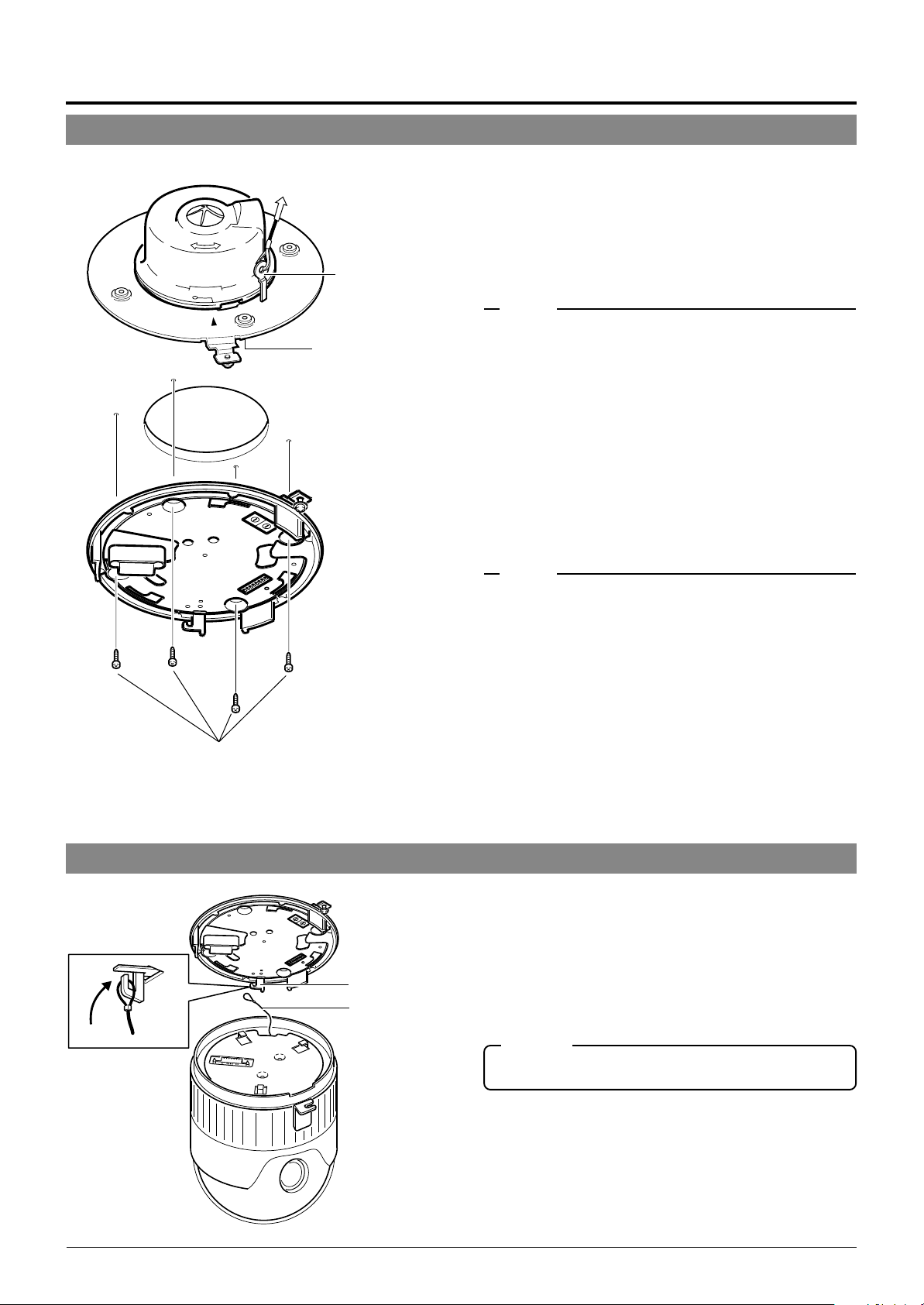
Attaching the Ceiling Mount
To a ceiling slab or channel
Safety wire hole
Ceiling mount
Rubber packings
(Four on each side)
1.
Attaching a safety wire.
Attach a safety wire to the ceiling mount and to the ceiling slab or channel to prevent the unit from dropping.
First attach the safety wire to the ceiling mount by passing the wire through the safety wire hole (see the diagram on the left).
MEMO
● Connect the wire so that it can be insulated from the ceiling struc-
ture. If the ceiling structure is made of a metallic material, improper insulation with the camera may produce noise in the video.
● Use a wire and ceiling attachment having sufficient length and
strength to prevent danger in case the camera drops.
● A safety wire is not provided. Please select an appropriate com-
mercially available wire.
2.
Attaching the ceiling mount to the ceiling.
While taking care not to catch the connection cables, attach the ceiling mount to the ceiling using four screws
(as shown in the diagram). Use M4-sized screws or bolts.
If woodscrews are used, use those with a diameter of 4.1
mm.
Screws
Attaching the Camera
Attach Drop
Prevention Wire
to this hook.
Drop Prevention
Wire
MEMO
● Be sure to use four screws and attach them firmly. If the screws
are not tightened firmly, dust and moisture may penetrate through
the screw holes.
● The rubber packings attached to the ceiling mount screw holes of
the ceiling mount play the role of insulation in case the ceiling
structure is made of a metallic material as well as the role of drip
proofing. If the ceiling structure is made of a metallic material,
improper insulation with the camera may produce noise in the
video. To prevent this occurring, be sure to ensure correct insulation of the installation.
1.
Attach the drop prevention wire.
As shown in the diagram, take the drop prevention wire
from the camera and attach it to the hook on the ceiling
mount.
Be sure to connect the drop prevention wire. Otherwise,
the camera will not fit properly to the ceiling mount. If
they are engaged forcibly, they may be damaged.
CAUTION
Be sure to attach the drop prevention wire. Otherwise, the camera is in danger of falling.
E-16
Page 17

Ceiling Mount
Camera
Camera clamping bracket
Lock screw
Camera clamping
bracket
2.
Ensure that the lock screw is loose.
The camera cannot be attached properly if the lock screw
of the Ceiling Mount is too tight.
3.
Fit the camera.
Check the position of the camera clamping bracket and
that of the lock screw, and fit the camera onto the ceiling
mount.
ENGLISH
Lock screw
Rotate the camera
clockwise.
4.
Rotate the camera.
Make sure that the camera is horizontal, then turn the
camera clockwise until it stops. Ensure that the cameraclamping bracket is in line with the lock screw of the Ceiling Mount.
5.
Tighten the lock screw.
Tighten the lock screw using a Phillips screwdriver.
CAUTION
If the lock screw is not tightened firmly, the camera may rattle or
fall down. Be sure to tighten the lock screw firmly.
* To remove of the camera from the ceiling
1
mount, reverse the steps
to 5.
Tighten the lock screw.
E-17
Page 18
Setting Up the Camera Using an RM-P2580
Setup Procedure
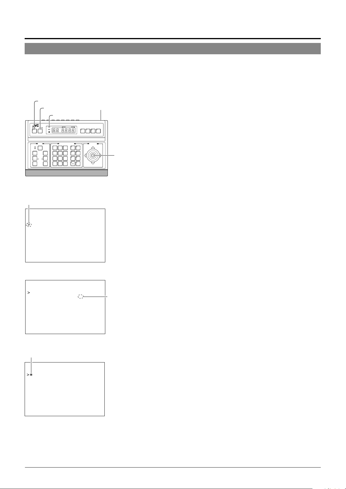
In systems using an RM-P2580 remote control unit, the menus for use during camera setup can be displayed on the remote control
unit. (Please refer to the instructions for RM-P2580.)
<Setting the camera menus from an RM-P2580>
MENU button
SET button
Power switch
(Rear panel)
POWER lamp
REMOTE CONTROL UNIT
SETUP
MENU SET
CLOSE
NEAR
WIDE
SPEED
IRIS
FOCUS
AF
ZOOM
POWER
ALARM
KEY LOCK
OPEN
FAR
TELE CLEAR
CAMERA POSITION
CAMERA/POSITION
1
2
3
4
5
6
7
8
9
0
ENTER
/HOME
CAMERA
OPTION1OPTION
AUTO
PAN
POSI-
PATROL
AUTO F-1 F-2 F-3
TION
2
AUTO
RM-P2580
PAN/TILTLENS
cursor
POSITION SETUP. .
CAMER A . .
CONTROL UN I T . .
SETUP
SETUP menu of the remote control unit
PAN/TILT
lever
1.
Set the Power switch on the rear panel of the RMP2580 to ON.
The POWER lamp lights up.
2.
Press and hold the MENU button for 3 seconds.
• The LED of the MENU button lights up.
• The SETUP menu of the remote control unit is displayed on the
monitor connected to MONITOR OUTPUT-1.
3.
Move the PAN/TILT lever downward to move the
cursor (>) to “CAMERA” in the menu.
• Tilting the lever upward () moves the cursor upward.
• Tilting the lever downward (
4.
Press the SET button.
• The MENU screen for the camera is displayed.
• Items followed by “..” have further submenus.
) moves the cursor downward.
CAM . FUNC T I ON . .
CAM. T I T L E / AL ARM. .
CAM. V I DEO ADJUST . .
CAM. ALC / Ex DR . .
HOME MOT I ON D ET ECT . .
AUTO PAN / PATROL / TRACE. .
POS I . FUNCT I ON SE T . .
FACTORY SETT I NGS . .
–––M E N U –––
SETUP menu of the camera
Change mark
–––CAMERA FUNC T I ON –––
POS.TITLE LOC. UP-L
FLIP DIGITAL
VAR.P/T SPEED ON
EASY AF OFF
D.ZOOM MAX X2
PRI VATE MASK. .
Example of a submenu
Indication of
presence of
submenus
5.
Tilt the PAN/TILT lever up or down to select an item.
6.
Tilt the PAN/TILT lever to the left or right to change
the value of the item.
• Tilting the lever toward the left ( ) decreases the value.
• Tilting the lever toward the right (
7.
Press the MENU button.
After completing the setup of the menu items, press the MENU button to return to the previous menu screen.
) increases the value.
E-18
Page 19
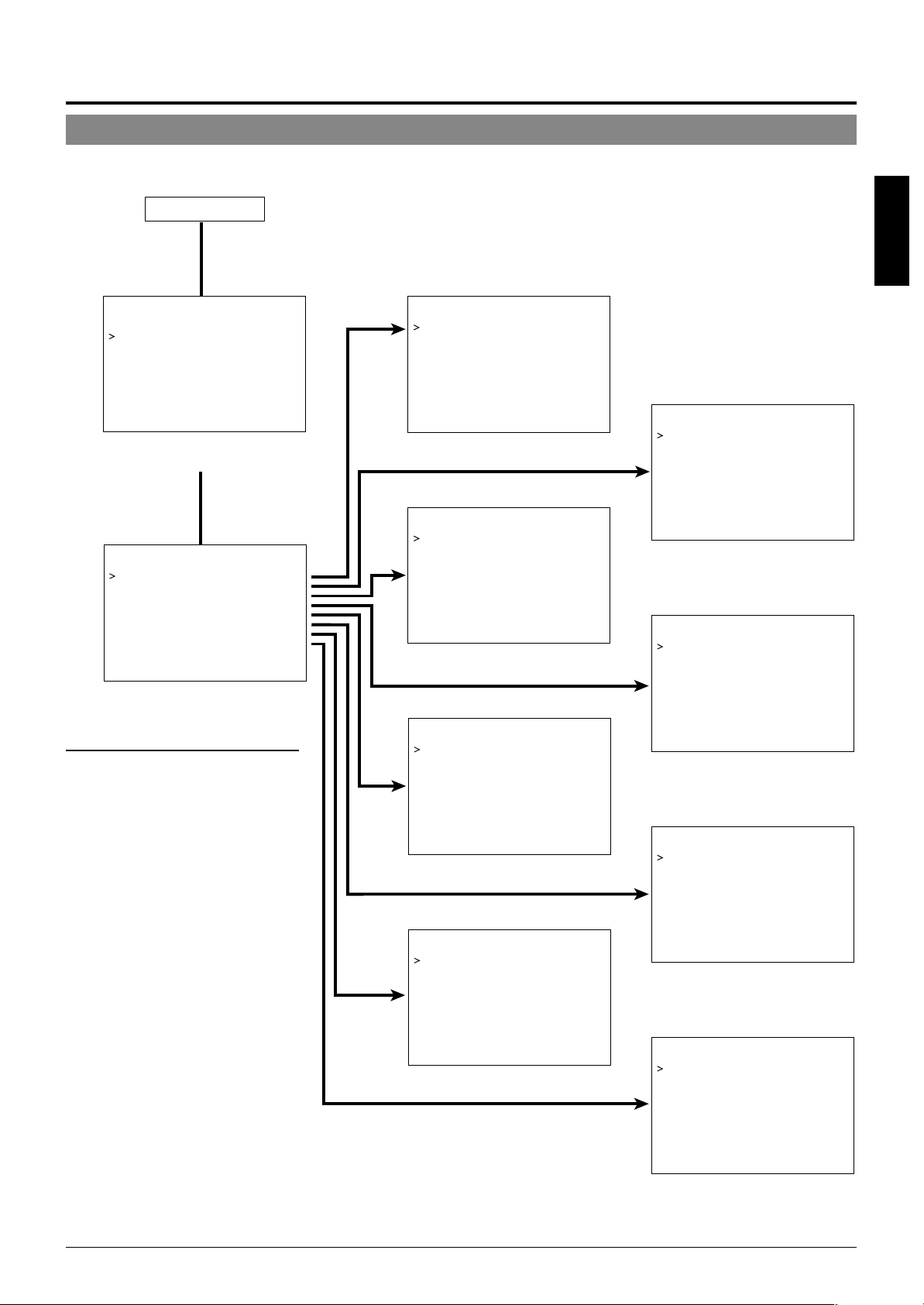
Menu Screen Flow
The menu screens are arranged in a hierarchical structure as shown below. Refer to the respective reference pages for the details of each
menu.
Normal screen
P.20
☞
ENGLISH
POS I T I ON SETUP . .
CAMERA. .
CONT ROL UN I T . .
SETUP
SETUP screen of the remote control unit
––– M E N U – ––
CAM. FUNCT I ON . .
CAM. T ITLE/ ALARM. .
CAM. V I DEO AD JUST . .
CAM. ALC / E xDR . .
HOME MOT I ON DETE CT . .
AUTO PAN / PATROL/ TRACE . .
POS I . FUNCT I ON S ET . .
FACTORY SETT I NGS. .
c
MENU screen
• Menus for setting up the function of
each camera:
CAM. FUNCTION
CAM. TITLE/ALARM
CAM. VIDEO ADJUST
CAM. ALC/ExDR
AUTO PAN/PATROL/TRACE
• Menu for setting up the home position only:
HOME MOTION DETECT
• Menu for setting up the function of
each preset position:
POSI. FUNCTION SET
––CAMERA F UNCT I ON – –
V.PHASE 0
POS . T I T L E LOC . UP - L
FLIP DIGITAL
VAR. P / T SPEED ON
EASY AF OFF
D.ZOOM MAX X2
PRIVATE MASK. .
CAMERA FUNCTION screen
P.23
☞
–––CAMERA V I DEO ADJ UST –––
COLOUR LEVE L NORMAL
ENHANCE LE VE L NORMA L
PEDESTAL LEVE L NORMAL
AUTO B LK . CT L . OFF
CAMERA VIDEO ADJUSTMENT screen
P.26
☞
–––HOME MOT I ON DE T EC T – ––
MOD E OF F
LEV EL NORMAL
AREA EDI T . .
ALARM D I SPLAY 5s
DEMONSTRAT I ON . .
HOME MOTION DETECT screen
P.28
☞
––POSITION FUNCTION SET – –
POSITION TITLE..
I R I S MODE AUTO
BLC OFF
W.BALANCE ATW
R-B GAIN –––
M-G GAIN –––
P.21
☞
–––CAMERA T I TLE / A LARM
CAM.TITLE EDIT. .
AREA T I TL E OFF
AREA TITLE EDIT..
ALM . T I T L E S I ZE DOU BLE
ALM.T I TLE COLOUR WHI TE
ALARM T I TLE ED I T . .
AL ARM I NPUT . .
ALARM OUTPUT . .
–––
CAMERA TITLE/ALARM screen
P.23
☞
–––CAMERA A LC / Ex DR
AVERAGE : PEAK 8 : 2
SHUTTER 1 / 50
AGC MODE 10 dB
SENSE UP OFF
PR I OR I TY MOT I ON
Ex DR MODE OFF
ExDR LEVEL –––
B&W / COLOUR MODE . .
–––
CAMERA ALC/ExDR screen
P.27
☞
––AUTO PAN / PATROL / TRACE
AUTO PAN MODE RETURN
AUTO PAN SPEED NORMAL
A . PAN START POS . SET . .
A.PAN RETURN POS.SET. .
AUTO PA TROL SET . .
AUTO TRACE SE T . .
RM. A . PAN KEY A . PAN
RM. A . PA TROL KEY A. PATROL
––
AUTO PAN/PATROL/TRACE screen
P.28
☞
POSITION FUNCTION SET screen
––FACTOR Y SE T T I NGS – –
CANCEL
CLEAR(W/ O POSI . T ITLE )
CLEAR( AL L )
FACTORY SETTINGS screen
E-19
Page 20

Setting Up the Camera Using an RM-P2580
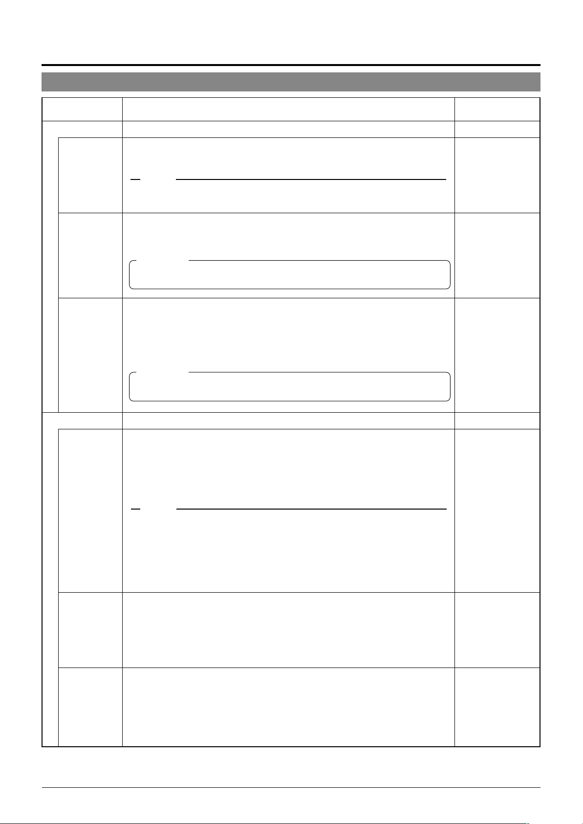
CAMERA FUNCTION Screen
This screen sets up the functions of the camera itself.
Item
V. PHASE
POS. TITLE LOC.
FLIP
VAR. P/T SPEED
Function & Setting
This adjusts the vertical synchronization to those of other cameras when a selector
switch for the synchronizing system on the Ceilling Mount is at LL. (50 Hz power
region only.)
When it is not set to LL, “---” will appear, disabling change the set value.
Setting values : –156 to 0 to 156
Sets the location of the position title and area title in the monitor.
UP : At the top of the screen.
DOWN : At the bottom of the screen.
L : In the left half of the screen.
C : In the center of the screen.
R : In the right half of the screen
Setting values : UP-L, UP-C, UP-R, DOWN-L, DOWN-C, DOWN-R
When a tilting operation is started while this item is OFF, the camera will stop at the
position where it is pointing straight downwards. When an object moves directly
below the camera, the camera makes three movements
ward
The FLIP function makes it possible to reduce these operations. Use this function
when monitoring an object passing directly below the camera.
OFF : Turns the FLIP function off.
DIGITAL : Once the camera reaches a tilt of 135 degrees from horizontal after
AUTO : When the camera reaches a position facing directly downwards, it pans
Under this function, the panning and tilting speeds are adjusted automatically relative to the zoom ratio of the lens. Setting the zoom lens towards TELE decreases
the pan and tilting speeds.
Setting the zoom lens towards WIDE end increases the pan and tilting speeds.
Use this function when monitoring objects at differing zoom ratios.
OFF : Turns this function off.
ON : Turns this function on.
pans 180° 3 points upwards.
2
passing a position facing directly downwards, a picture is inverted both
vertically and horizontally.
by 180° then stops.
points the straight down-
1
Initial Value
0
UP-L
DIGITAL
ON
EASY AF
D. ZOOM MAX
PRIVATE MASK..
When this item is set to ON, the auto focusing (AF) is activated automatically during manual pan/tilt and zoom operations.
This function is convenient when frequent manual operations are expected as it
eliminates the need to focus manually after every manual operation.
OFF : Turns this function off.
ON : Turns this function on.
MEMO
Auto focusing may sometimes be incapable of bringing certain objects into accurate focus.
(☞ P. 4 )
In this case, use the manual focusing facility.
When the zoom lens is set toward TELE, optical zooming is activated first and
electronic zooming second. This function sets the maximum zoom ratio of the
electronic zooming.
Setting values : x1, x2, x4, x6, x8, x10.
MEMO
● Note Picture quality deteriorates under electronic zooming as it is accompanied by digital
image processing.
● An increase in the electronic zooming ratio may deviate the center of the image slightly
toward the top left. This is due to the camera properties and is not a malfunction.
● Continuous operation from optical zooming to electronic zooming is not available. When
optical zooming reaches the TELE end, press the TELE button again.
This function grays out sections that are not to be displayed in the monitored picture area.
The grayed out section moves accordingly when the camera is panned, tilted or
when the zoom is adjusted.
P.29, “PRIVATE MASK Setup”
☞
OFF
x2
–
E-20
Page 21

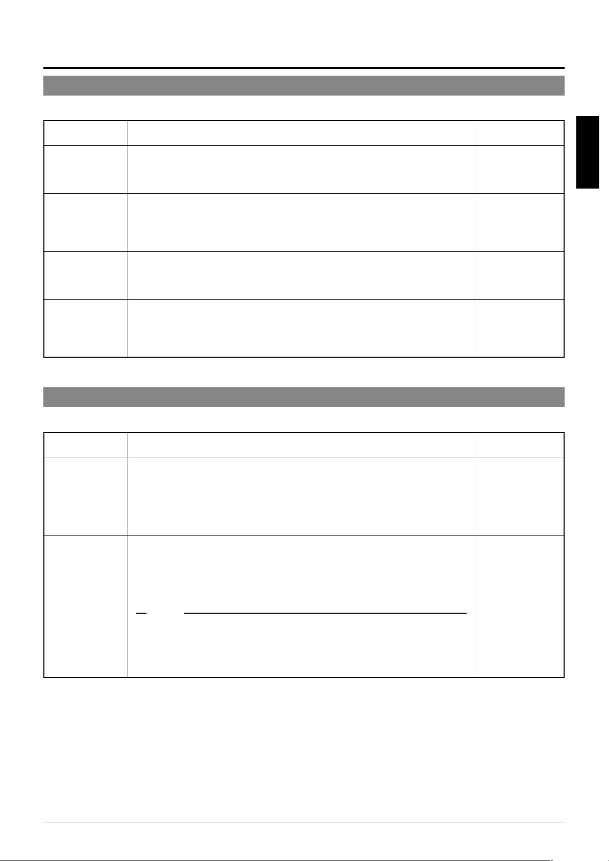
CAMERA TITLE/ALARM Screen
This screen sets items related to titles and alarms.
Item
CAM. TITLE EDIT
AREA TITLE
AREA TITLE EDIT
ALM. TITLE SIZE
ALM. TITLE COLOUR
ALARM TITLE EDIT
ALARM INPUT
Function & Setting
..
This sets the title which is displayed permanently at the bottom left of the picture.
This title can be up to 16 characters in length.
P. 30, “CAMERA TITLE Setup”
☞
The 360° panning range can be divided into 16 areas and a title, of up to 16character in length, can be set for each area. As the camera is panned manually
these area titles are displayed. This function determines whether area titles are
displayed or not.
ON : Display area titles.
OFF : Do not display area titles.
..
Sets the area titles.
P. 31, “AREA TITLE Setup”
☞
Sets the size of the characters in the alarm title. (Displayed when an alarm is activated.)
NORMAL : Same size as the characters used in the menu screen.
DOUBLE : Double the size, both horizontally and vertically, of the characters used
Sets the color of the alarm titles.
Setting values: WHITE, YELLOW, CYAN, GREEN
..
Sets the alarm titles.
P. 32, “ALARM TITLE Setup”
☞
..
Sets the configuration of the alarm input terminals on the Ceiling Mount.
The picture can be turned black-and-white mode when an alarm signal is input.
P. 25, Item “B&W”
☞
in the menu screen.
MEMO
● When the item “B&W” is set to ALARM 1 to 4, [B&W] will be displayed at the correspond-
ing ALARM IN 1 to 4 items and the setting cannot be varied.
● When ALARM IN 1 to 4 are set to positions between POS 64 and POS 99, switching to
the preset position does not occur even when an alarm signal is input.
Initial Value
–
ENGLISH
OFF
–
DOUBLE
WHITE
–
–
ALARM IN1
ALARM IN2
ALARM IN3
ALARM IN4
Sets the camera position for alarm 1. When an alarm signal is input to the Alarm 1
input terminal, the camera moves to this set position.
HOME means the home position and POS1 means position 1.
Setting values: OFF, HOME, POS1 to POS99.
Sets the camera position for alarm 2. When an alarm signal is input to the Alarm 2
input terminal, the camera moves to this set position.
HOME means the home position and POS1 means position 1.
Setting values: OFF, HOME, POS1 to POS99.
Sets the camera position for alarm 3. When an alarm signal is input to the Alarm 3
input terminal, the camera moves to this set position.
HOME means the home position and POS1 means position 1.
Setting values: OFF, HOME, POS1 to POS99.
Sets the camera position for alarm 4. When an alarm signal is input to the Alarm 4
input terminal, the camera moves to this set position.
HOME means the home position and POS1 means position 1.
Setting values: OFF, HOME, POS1 to POS99.
OFF
OFF
OFF
OFF
E-21
Page 22
Setting Up the Camera Using an RM-P2580
CAMERA TITLE/ALARM Screen (Continued)
Item
ALARM INPUT
POLARITY
DURATION
PRIORITY
Function & Setting
..
(Continued)
Sets the polarity of the alarm signal inputs.
MAKE : Alarm signals are transmitted when point of contact is made.
BREAK : Alarm signals are transmitted when contact is broken.
MEMO
When an item for the B&W is set to the ALARM 1 to 4, it is set to the MAKE mode even if
“BREAK” is displayed.
Sets the length of an alarm operation once an alarm signal has been transmitted.
(Unit:second)
Setting values : 5s, 6s, 7s, 8s, 9s, 10s, 15s, 20s, 30s or 60s
CAUTION
This item is invalid with the system using the RM-P2580. When using the RM-P2580, use
item “ALARM TIME” instead.
Sets whether or not manual operation is accepted in case an alarm input is recognized during manual operation of the camera.
ALARM : Manual operation is not accepted when there is an alarm input.
MANUAL : Manual operation is accepted even when there is an alarm input.
(Priority on alarm)
(Priority on manual)
CAUTION
This item is invalid with a system using the RM-P2580. With this system, the ALARM input
is permanently given the priority.
Initial Value
MAKE
5s
ALARM
ALARM OUTPUT
ALARM OUT1
ALARM OUT2
ALARM OUT3
..
Sets the configuration of the alarm output terminals on the Ceiling Mount.
Sets the configuration of the Alarm output 1 terminal.
OFF : Does not output an alarm signal.
ALARM : Alarm signal is output upon input of motion detection or an alarm signal.
B&W : Alarm signal is output when the camera enters the B&W mode.
PRESET : Alarm signal is output when a camera moves to a preset position.
AUX1 to 3 : Alarm signal is output when a corresponding AUX signal is input. (This
is variable depending on the remote control unit in use.)
MEMO
● Since the ALARM OUT 1 terminal employs a mechanical relay, its operating sound may
seem noisy in a quiet environment. In this case, use the ALARM OUT 2 or 3 terminal
instead.
● Sine the ALARM OUT 1 terminal employs a mechanical relay, the service life of the relay
may be shortened if signals causing an alarm (motion detect signal, etc.) are applied frequently. The service life of a relay is 200,000 times of operation. The relay is a consumable
part and a replacement is chargeable even before the termination of the warranty period.
Sets the configuration of the Alarm output 2 terminal.
OFF : Does not output an alarm signal.
ALARM : Alarm signal is output upon input of motion detection or an alarm signal.
B&W : Alarm signal is output when the camera enters the B&W mode.
PRESET : Alarm signal is output when a camera moves to a preset position.
AUX1 to 3 : Alarm signal is output when a corresponding AUX signal is input. (This
Sets the configuration of the Alarm output 3 terminal.
OFF : Does not output an alarm signal.
ALARM : Alarm signal is output upon input of motion detection or an alarm signal.
B&W : Alarm signal is output when the camera enters the B&W mode.
PRESET : Alarm signal is output when a camera moves to a preset position.
AUX1 to 3 : Alarm signal is output when a corresponding AUX signal is input. (This
is variable depending on the remote control unit in use.)
is variable depending on the remote control unit in use.)
–
ALARM
ALARM
ALARM
E-22
Page 23
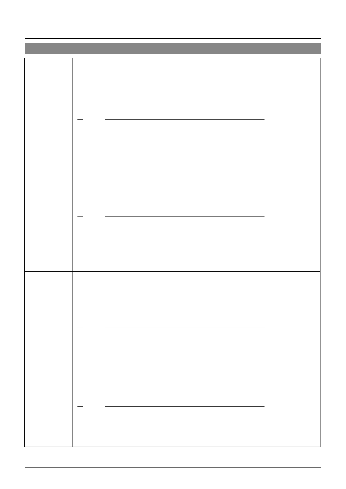
CAMERA VIDEO ADJUSTMENT Screen
This menu sets the picture signal of the camera, such as the color level and contour enhancement.
Item
COLOUR LEVEL
ENHANCE LEVEL
PEDESTAL LEVEL
AUTO BLK. CTL
Sets the color level of the picture signal.
To increase : Set a smaller value.
To decrease : Set a larger value.
Setting values : –5 to NORMAL to 5.
Sets the contour enhancement which controls the sharpness of the monitor picture.
To soften the picture : Set a smaller value.
To sharpen the picture : Set a larger value.
Setting values : –5 to NORMAL to 5.
Sets the pedestal level (black level) of the video signal.
To darken the picture : Set a smaller value.
To brighten the picture : Set a larger value.
Setting values : –5 to NORMAL to 5.
Use this function when darker parts of a picture are unclear even after the gain has
been increased using the AGC (Auto Gain Control).
ON : When the black level of the video signal is low, the pedestal level is in-
creased automatically in order to improve the clarity of the darker parts.
OFF : Turns this function off.
Function & Setting
CAMERA ALC/ExDR screen
This screen adjusts the settings of automated functions relating to picture brightness.
Initial Value
NORMAL
ENGLISH
NORMAL
NORMAL
OFF
Item
AVERAGE : PEAK
SHUTTER
Function & Setting
Sets the method of exposure detection to the ratio between the average and peak
values.
Large Average value
Large Peak value : Use this setting when highlighted areas appear as halation.
Setting values : 10:0, 9:1, 8:2, 7:3, 6:4, 5:5
Sets the electronic shutter speed.
When the item “SENSE UP” is set to “x2” or higher, the, available settings for the
SHUTTER are limited to 1/100 and 1/120.
When the item “ExDR MODE” is set to “ON”, the available settings for the SHUT-
TER are limited to 1/50 and 1/120.
Setting values : 1/50, 1/120, 1/250, 1/500, 1/1000, 1/2000, 1/4000, 1/10000
: Use this setting when areas other than the highlighted ar-
eas are filled with dark. (Example: 10:0)
(Example: 5:5)
MEMO
To reduce the flickering which occurs under fluorescent lighting, set the shutter speed
●
to 1/100 if your local power supply frequency is 50 Hz and to 1/60 if it is 60 Hz.
● When a high shutter speeds are used, white stripes may be observed above and
below bright objects. This is called the smear phenomenon and is usual to CCD
cameras.
Initial Value
8:2
1/50
E-23
Page 24
Setting Up the Camera Using an RM-P2580
CAMERA ALC/ExDR Screen (Continued)
Item
AGC MODE
SENSE UP
PRIORITY
Function & Setting
Sets the maximum gain of the AGC (Auto Gain Control), which electronically increases the gain when the object is under low light conditions.
OFF : Turns the AGC off.
10 dB : According to the brightness of the object, gain is increased by up to 10 dB
20 dB : According to the brightness of the object, gain is increased by up to 20 dB
SUPER : Use this setting when brightness is still insufficient under the “20 dB”
setting.
MEMO
When the item “B&W” is set to “AUTO”, [SUPER] is displayed when the item “AGC MODE”
●
is set to “SUPER”, and [20 dB] is displayed for other settings. Increase the gain up to the
value displayed.
● Note that increasing gain affects picture quality.
● When the “SUPER” setting is used, the AGC operation may take a while to adjust to
sudden drastic changes in the brightness level.
This function is used to increase the sensitivity by extending the exposure time.
When the object is dark, this functions sets how high the level of sensitivity will
automatically increase to “x32” means that the sensitivity will be increased continuously up to 32 times the normal level.
Increasing this value slows the shutter speed and motion may appear unnatural.
When the item “SHUTTER” is set to “1/250” or more, the SENSE UP item does not
work and “---“ is displayed as the item name in the CAMERA ALC/ExDR Screen.
Setting values: OFF, x2, x4, x8, x16, x24, x32
MEMO
● As the setting of the “SENSE UP” function is increased, the picture may become rough
and whitish, and subject to white blemishes. This is not a malfunction.
● When the setting of the “SENSE UP” function is not OFF, flicker may appear on the
screen under fluorescent light or mercury lamps. This is due to the principles of the
SENSE UP, and is not a malfunction.
● There may be cases where flicker can not be reduced even under the following condi-
tions: 1) Shutter speed is set at 1/120 in areas where the commercial electric current
frequency is 50 Hz. 2) The shutter speed is set at 1/50 in areas where the commercial
electric current frequency is 60 Hz..
When an object is dark, this functions sets whether priority during monitoring is
placed on maintaining the motion of the camera or on picture quality.
MOTION : Motion of the camera is given priority. When an object is dark, the
PICTURE : Picture quality is given priority. When an object is dark, the SENSE UP
AGC function is prioritized. This setting is suitable when objects are
characterized by quick motion.
function is prioritized. This setting is suitable when picture quality is
important.
Initial Value
10 dB
OFF
MOTION
ExDR MODE
E-24
MEMO
● When the “AGC MODE” and “SENSE UP” functions are both set to “OFF”, this function
does not work and “---” is displayed as the item name in the CAMERA ALC/ExDR Screen.
● When item “B&W” is set to AUTO, item “PRIORITY” is set to the MOTION priority mode
and “---” is displayed.
The ExDR function synthesizes pictures captured at a shutter speed of 1/100 and
those captured at higher shutter speeds to help monitor objects having large differences in brightness levels.
When the “SHUTTER” function is set to “1/250” or a higher, this function does not
work and “---” is displayed as the item name in the CAMERA ALC/ExDR Screen.
OFF : Turns the ExDR function off.
ON : Turns the ExDR function on.
MEMO
● When the ExDR function is on, flicker may appear on the screen under fluorescent light
or mercury lamps. This is due to the principles of the ExDR, and is not a malfunction.
● There may be cases where flicker cannot be reduced even under the following condi-
tions: 1) Shutter speed is set at 1/120 in areas where the commercial electric current
frequency is 50 Hz. 2) The shutter speed is set at 1/50 in areas where the commercial
electric current frequency is 60 Hz.
OFF
Page 25

Item
Function & Setting
Initial Value
ExDR LEVEL
B&W/COLOUR
...
MODE
B&W
This function sets which section of the object is to be displayed in the easiest-toview brightness level in the ExDR mode.
To make a low-light section of the object easy to view: Increase the level.
To make a highlighted section of the object easy to view: Decrease the level.
Setting values: –5 to NORMAL to 5
MEMO
● When the difference in brightness between objects is large, the picture may not change
even when the ExDR LEVEL is varied. This is due to the characteristics of the camera
and is not a malfunction.
● When the item “SHUTTER” is set to 1/250 or higher, “---“ is displayed and the settings to
the item “ExDR LEVEL” cannot be carried out.
● When the item “ExDR MODE” is set to OFF, the settings for the item “ExDR LEVEL”
cannot be varied.
This function sets the color modes to color or B&W.
When switching the mode between “color” and “B&W” is carried out, the focus may
be dislocated. In such a case adjust the focus again.
Switches the mode from color to B&W and vice-versa.
OFF : Turns the B&W mode switching function off.
ON : Sets the camera permanently to B&W mode.
AUTO : The camera automatically switches to Color mode when the ob-
ject is bright and to B&W mode when it is dark.
ALARM IN 1 to 4
: The camera switches to B&W mode when there is an alarm
input from terminals Alarm 1 to Alarm 4.
The B&W mode is set to ON when the contact is shorted (makes
contact) and OFF when the contact is opened (breaks contact).
MEMO
● To ensure switching between the color and B&W modes:
Setting item “B&W” to AUTO allows the color and B&W modes to be switched according
to the brightness of the object. However, this switching may sometimes not occur depending on the lighting condition and viewing angle.
To ensure the switching, it is recommended to connect the signal from an external sensor (to be purchased separately by the user) to one of the ALARM input terminals of the
camera and perform switching according to the sensor signal.
● In order to prevent hunting do not set the item “B&W” to AUTO when using an infrared
lamp.
NORMAL
ENGLISH
OFF
LEVEL
LIGHT TYPE
When the “B&W” function is set to “AUTO”, this function sets the signal level of the
object at which the camera will automatically switch to B&W mode.
LOW : The camera switches to B&W mode when the signal level of the object
is low.
NORMAL : The camera switches to B&W mode when the signal level of the object
is normal.
HIGH : The camera switches to B&W mode when the signal level of the object
is high.
MEMO
When the item “B/W” is set to other than AUTO, “---“ is displayed and the settings to the item
“LEVEL” cannot be varied.
Use this function to set the type of light illuminating the object in the B&W mode.
NORMAL : Setting for normal lighting.
IR : Setting for using IR lighting.
MEMO
If the IR setting is used under ordinary sunlight or fluorescent light, the switching between
the color and B&W modes will not be performed correctly.
NORMAL
NORMAL
E-25
Page 26
Setting Up the Camera Using an RM-P2580
HOME MOTION DETECT Screen
When the camera is in the home position:
This screen sets the motion detect function, which outputs an alarm signal when motion is detected in the monitored picture. The
alarm signal is output from the alarm output terminal on the terminal board.
Item
MODE
LEVEL
AREA EDIT..
ALARM DISPLAY
Function & Setting
Turns the motion detect function on and off.
OFF : Defeats this function.
ON : Activates this function.
Sets the level at which motion is identified.
When the item “MODE” is set to “OFF”, this item does not work and “---” is dis-
played as the item name in the HOME MOTION DETECT Screen.
• To detect motions characterized by large changes in the signal level
: Decrease the setting value.
• To detect motions characterized by small changes in the signal level
: Increase the setting value.
Setting values : -5 to NORMAL to 5
MEMO
When the setting value of the detection level is increased, it sometimes causes the fluorescent lamp to flicker.
Check the performance at the DEMONSTRATION item after changing the setting.
Sets of the area of the picture within which the motion detect function operates.
P. 33, “HOME MOTION DETECT Setup”
☞
Sets the length of an alarm signal and the alarm display output when
motion is detected.
When the item “MODE” is set to “OFF”, this item is does not work and “---” is dis-
played as the item name in the HOME MOTION DETECT Screen.
Setting values : OFF, 5s, 6s, 7s, 8s, 10s, 15s, 20s, 30s, 60s
MEMO
When the item “MODE” is set to OFF, an alarm signal is output from the alarm output terminal but the alarm display is not shown in the picture.
Initial Value
OFF
NORMAL
–
5s
CAUTION
This item is invalid with the system using the RM-P2580. When using the RM-P2580, use
item “ALARM TIME” instead.
DEMONSTRATION
This function is used to confirm the setup of the motion detect function.
–
MEMO
● Demonstration function is invalid when the camera is in a position other than the home position.
● The motion detect function is not activated when the camera is panned, tilted or zoomed in the home position.
● When the iris or focus operation is performed while the camera is in the home position, the motion detect function is not activated for 5 seconds
after completion of the operation.
● During auto patrol, the motion detect function cannot be activated even when the camera is in the home position.
E-26
Page 27

AUTO PAN/PATROL/TRACE Screen
This screen sets up the auto pan function for slow panning, the auto patrol function for switching of positions in sequence, and the
auto trace function for the reproduction of the results of manual camera operations.
Item
AUTO PAN MODE
AUTO PAN SPEED
A. PAN START
POS. SET..
A. PAN RETURN
POS. SET..
AUTO PATROL SET
AUTO TRACE SET
RM. A. PAN KEY
RM. A. PATROL KEY
Function & Setting
Determines movement during auto panning.
RETURN : Moves continuously between start and return positions.
RIGHT : Clockwise rotation
LEFT : Counterclockwise rotation.
P. 34, “AUTO PAN Setup”
☞
Sets the rotation speed during auto panning.
LOW : Low speed.
NORMAL : Normal speed.
HIGH : High speed.
Sets the auto panning start position.
Sets the auto panning return position.
Sets the configuration of the auto patrol function.
P. 35, “AUTO PATROL Setup”
☞
Sets the configuration of the auto trace function.
P. 36, “AUTO TRACE Setup”
☞
Determines the function activated by pressing the AUTO PAN button on the remote
control unit.
A. PAN : Auto pan function.
A. PATROL : Auto patrol function.
A. TRACE : Auto trace function.
Determines the function activated by pressing the AUTO PATROL button on the remote control unit.
A. PAN : Auto pan function.
A. PATROL : Auto patrol function.
A. TRACE : Auto trace function.
Initial Value
RETURN
NORMAL
–
–
–
–
AUTO PAN
AUTO PATROL
ENGLISH
E-27
Page 28
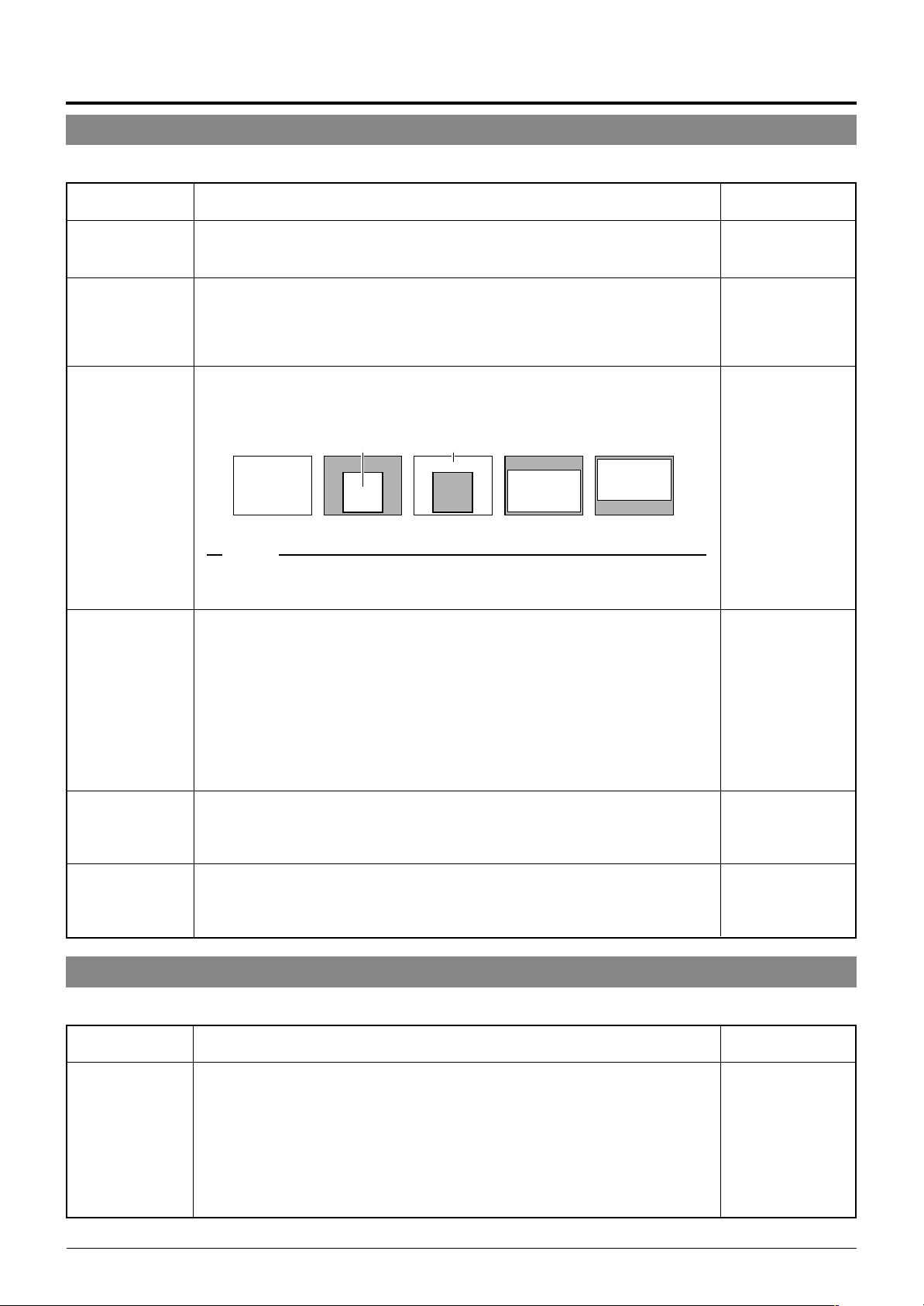
Setting Up the Camera Using an RM-P2580
POSITION FUNCTION SET Screen
This screen sets the configurations of functions relating to pictures taken in preset positions.
Item
POSITION TITLE
IRIS MODE
BLC
W. BALANCE
Function & Setting
...
Sets the titles for the 99 preset positions and the home position. Titles can be up to
16 characters in length and are shown in the display.
P. 37, “POSITION TITLE Setup”
☞
Determines the lens iris adjustment mode.
AUTO : for auto iris adjustment under standard conditions.
AUTO+ : for auto iris adjustment under slightly brighter conditions.
AUTO– : for auto iris adjustment under slightly dimmer conditions.
MANUAL : for manual iris adjustment.
Sets of area of back light compensation. Use this function when the object appears dark (under auto iris control) because of the presence of a bright light source
behind it. This function make it possible to place the unnecessary light source outside the photometry area.
Photometry area
Photometry area
OFF AREA 1 AREA 2 AREA 3 AREA 4
Photometry area
Photometry area
Photometry area
MEMO
When the item “ExDR MODE” (
“---” is displayed. Under this condition, the settings to the item “BLC” cannot be varied.
Determines the setting of the white balance adjustment. The white balance can be
adjusted for lighting conditions with color temperatures from 2500K to 8000K.
ATW : Auto-Tracking White balance mode, adjusts the white balance automati-
cally according to the color temperature of the lighting conditions.
When ATW is set, “---“ is displayed for the items “R-B GAIN” and “M-G
GAIN”, so that the color phase adjustment cannot be carried out.
AWC : Auto White Control mode, which displays “PUSH SET → ADJ. STRAT”.
When the SET button is pressed, AWC is activated and the white balance
adjustment starts.
If the AWC is activated while the screen is B&W the LOW LIGHT ERROR
will be displayed. This is not abnormal.
page 24) is set to ON, the item “BLC” is set to OFF and
☞
Initial Value
–
AUTO
OFF
ATW
R-B GAIN
M-G GAIN
Adjusts the phases of R (Red) and B (Blue) under AWC mode.
• To enhance blue: Decrease the value.
• To enhance red : Increase the value.
Setting values : 0 to 255
Adjusts the phases of M (Magenta) and G (Green) under AWC mode.
• To enhance green : Decrease the value.
• To enhance magenta : Increase the value.
Setting values : 0 to 255
FACTORY SETTINGS screen
This screen resets values to their factory settings.
Item
FACTORY
SETTINGS
Resets all settings in the above menus to their initial factory settings. Pressing the
SET button displays “EXECUTING” (2 sec. approx.) and resets the settings to the
factory settings.
CANCEL : Does not alter current values.
CLEAR (W/O POS. TITLE) : Resets the settings to the initial, factory settings.
CLEAR (ALL) :
Function & Setting
However, the set positions, the setting data of each
position and the titles are not reset to the factory settings.
Resets all settings including titles and stored positions.
95
63
Initial Value
–
E-28
Page 29
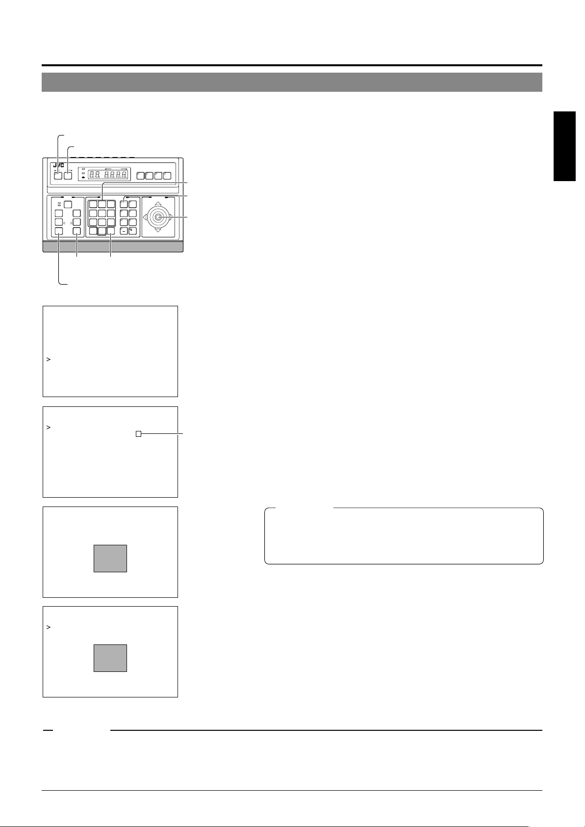
PRIVATE MASK Setup
Use the PRIVATE MASK screen to set up the private mask function, which grays out areas that are not required to be included in
the monitored picture. Up to four private masks can be set per screen, and up to eight private masks can be set in total.
1.
MENU button
SET button
SETUP
MENU SET
CLOSE
NEAR
WIDE
SPEED
IRIS
OPEN
FOCUS
FAR
AF
TELE CLEAR
ZOOM
TELE
button
KEY LOCK
POWER
ALARM
CAMERA POSITION
CAMERA/POSITION
1
2
4
5
7
8
0
/HOME
ENTER
button
REMOTE CONTROL UNIT
AUTO F-1 F-2 F-3
CAMERA
3
OPTION1OPTION
6
AUTO
9
ENTER
PAN/TILTLENS
POSITION
2
AUTO
PAN
PATROL
WIDE button
–––CAMERA FUNCT ION – ––
POS . T I TL E L OC . UP - L
FL I P DIG ITAL
VAR . P / T SPEED ON
EASY AF OFF
D.ZOOM MAX X2
PRIVATE MASK. .
–––PR I VA TE MASK – ––
MOD E ON
MAS K NO 1
MASK EDIT. .
MASK DELETE. .
*
RM-P2580
Numeric keys
CAMERA
buttons
PAN/TILT
lever
Already set.
Select the camera. (☞ RM-P2580 Instruction manual)
CAMERA button → Numeric key (camera number) → ENTER button.
The picture of the selected camera is output.
2.
Select the angle of view.
Use the PAN/TILT lever and the lens button to set the viewing angle
to which the private mask function is to be applied.
3.
Display the SETUP menu on the camera.
(☞ P. 18, steps 1 to 4)
→
MENU button (3 sec.)
→
lever
SET button.
Select “CAMERA” using the PAN/TILT
The camera moves to the home position.
4.
Tilt the PAN/TILT lever up or down to move the cursor
(>) to “CAMERA FUNCTION” and press the SET button.
The CAMERA FUNCTION menu is displayed.
5.
Move the cursor (>) to “PRIVATE MASK” and press
the SET button.
The PRIVATE MASK submenu is displayed.
6.
Select the private mask function ON or OFF.
Turn the private mask function on or off by setting the “MODE” item
in the submenu to ON or OFF (Factory setting: OFF)
7.
Select the mask number.
Select the private mask number from MASK NO. 1 to 8 and move the
cursor on to the item “MASK EDIT.” Of these, a maximum of 4 can be set
within one picture.
If an already set mask number is selected, the (
8.
Edit the masking area.
• Move the cursor to “MASK EDIT” and press the SET button to
display the MASK EDIT screen. (The masked area will be displayed as a grayed-out area.)
• Tilt the PAN/TILT lever to move the grayed-out area to the center
of the area to be masked.
• Press the TELE and WIDE buttons to set the masked area size.
) mark will be displayed.
*
ENGLISH
CAUTIONS
–––MA SK E D I T – ––
PUSH MENU SAVE&RE TURN
–––MASK DEL ETE – ––
CANCEL
DEL ET E
→
● It is not possible to set five or more masks in adjacent areas. (Even when
this is attempted, the masked area that is required to be set will not be
displayed.)
● MASK cannot be set at lower than approx. 45° in the horizontal direction.
(The masks for new settings are not displayed.)
9.
Press the MENU button.
• The screen returns to the “PRIVATE MASK menu”.
•
To delete a private masked area, select “MASK DELETE”, move the cur-
sor to “DELETE” and press the SET button.
The PRIVATE MASK menu reappears after the data has been deleted.
To cancel deletion, select “CANCEL” and press the SET button.
10.
Repeat steps 6 to 9 for each additional masked area.
11.
Press the MENU button.
The screen returns to the “CAMERA FUNCTION” menu.
CAUTIONS
●
Depending on the camera direction, a picture may be shot even in the setting private mask area.
● The private MASK function cannot be carried out during the initializing process immediately after the power is turned on.
● If a high value is set in item “SENSE UP”, the masked object may be displayed depending on the camera orientation even when the object is
located within the private masking area.
● If the picture being shot contains 5 or more masks, the entire picture is masked.
E-29
Page 30
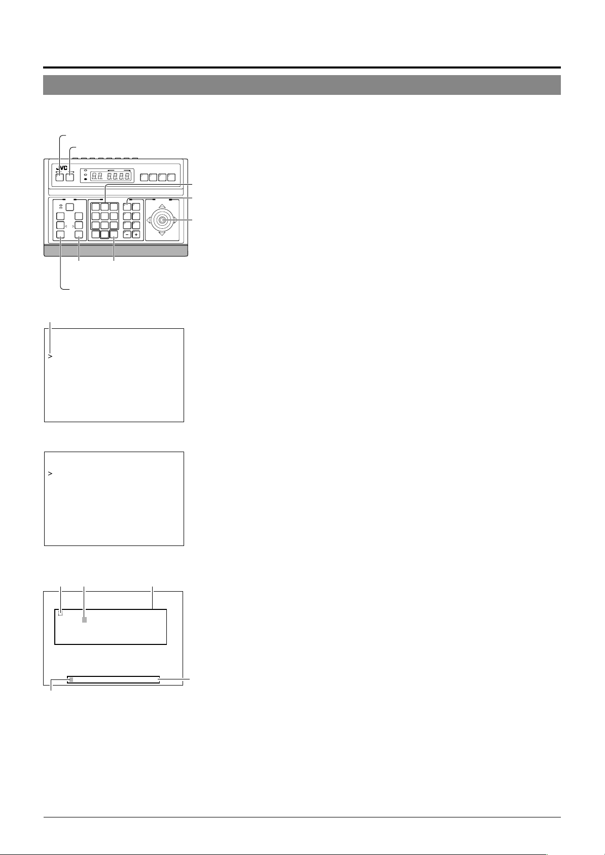
Setting Up the Camera Using an RM-P2580
CAMERA TITLE Setup
Use the CAMERA TITLE screen to set the title of each camera.
Titles can be up to 16 characters in length and are displayed at the bottom left of the picture.
MENU button
SET button
REMOTE CONTROL UNIT
SETUP
MENU SET
CLOSE
NEAR
WIDE
SPEED
IRIS
OPEN
FOCUS
FAR
AF
TELE CLEAR
ZOOM
TELE
button
KEY LOCK
POWER
ALARM
CAMERA POSITION
CAMERA/POSITION
2
3
1
5
6
4
9
7
8
0
ENTER
/HOME
ENTER
button
CAMERA
OPTION1OPTION
AUTO
PAN
PATROL
AUTO F-1 F-2 F-3
POSITION
2
AUTO
RM-P2580
PAN/TILTLENS
WIDE button
Cursor
–– – M E N U – ––
CAM . FUNC T I ON . .
CAM. T I T L E / AL ARM. .
CAM. V IDEO AD JUST . .
CAM. ALC / Ex DR . .
HOME MOT I ON D ET ECT . .
AUTO PAN / PATROL / TRACE. .
POS I . FUNCT I ON SE T . .
FACTORY SETT I NGS . .
SETUP menu display on the camera
Numeric keys
CAMERA
buttons
PAN/TILT
lever
1.
Select the camera. (☞ RM-P2580 Instruction manual)
CAMERA button → Numeric key (camera number) → ENTER button.
The picture of the selected camera is output.
2.
Display the SETUP menu on the camera.
(☞ P. 18, steps 1 to 4)
MENU button (3 sec.) → Select “CAMERA” with the PAN/TILT lever
→ SET button.
The camera moves to the home position.
3.
Tilt the PAN/TILT lever up or down to move the cursor (>) to “CAMERA TITLE/ALARM” and press the
SET button.
The TITLE/ALARM menu is displayed.
4.
Ensure that the cursor (>) is located on “CAMERA
TITLE” and press the SET button.
• The CAMERA TITLE screen is displayed.
• The first characters in the character area and title input field blink
to indicate that the system is ready for title input.
–––CAMERA T I TL E / AL ARM
CAM. T I T LE ED I T . .
AREA T I T LE OFF
AREA TITLE EDIT. .
ALM.T I TLE SI ZE DOUBLE
ALM.T I TLE COLOUR WH I TE
AL ARM T I T LE ED I T . .
AL ARM I NPUT . .
ALARM OUTPUT. .
TITLE ALARM menu
Space Blinking
–––CAMERA T I TL E– ––
0123456789ABCDEFGHI JK
LMNOPQRS T U VWX Y Z
h i j k lmnopqr s t uvwxyz . , '
– :/ДЦЬВКО ФЫЗСдлп цьвк о ф
ыбйнуъаи м тщзсЯ¡¿
←
WIDE TELE
Blinking
Character area
CAMERA TITLE screen
abcde f g
→
– ––
Title input
field
5.
Tilt the PAN/TILT lever to select the first character
of the title from the character area.
• The character being selected blinks.
• The selected character is displayed in the title input field.
6.
Press the TELE button.
• The first character of the title is input, and the camera gets ready
for the input of the second character.
• If the WIDE button is pressed, the blinking position in the title input field moves to the left. Use this facility to correct previously
input characters.
7.
Repeat steps 5 and 6 for each title character.
Complete the input of the title for the selected camera in this way.
8.
Press the MENU button.
• The screen returns to the previous menu.
1
• To set the titles for multiple cameras, repeat steps
camera.
to 7 for each
E-30
Page 31

AREA TITLE Setup
The 360° panning range of the camera can be divided into 16 equally sized areas and an area title can be set for each area. Titles can
be of up to 16 characters in length and are displayed in the picture as the camera is panned manually. (Area title display ON/OFF:
P. 21, Item “AREA TITLE”. Area title display position ☞ P. 20, Item “POS. TITLE. LOC.”)
1.
Select the camera. (☞ RM-P2580 Instruction manual)
CAMERA button → Numeric key (camera number) → ENTER button.
The picture of the selected camera is output.
2.
AREA
2
AREA
1
HOME
position
AREA
16
AREA
15
Display the SETUP menu on the camera.
(☞ P. 18, steps 1 to 4)
MENU button (3 sec.) → Select “CAMERA” with the PAN/TILT lever
→ SET button.
The camera moves to the home position.
MENU button
SET button
3.
SETUP
MENU SET
CLOSE
NEAR
WIDE
SPEED
IRIS
FOCUS
AF
ZOOM
POWER
ALARM
KEY LOCK
OPEN
FAR
TELE CLEAR
CAMERA POSITION
CAMERA/POSITION
1
2
3
4
5
6
7
8
9
0
ENTER
/HOME
CAMERA
OPTION1OPTION
AUTO
PAN
REMOTE CONTROL UNIT
AUTO F-1 F-2 F-3
POSITION
2
AUTO
PATROL
RM-P2580
PAN/TILTLENS
CAMERA
buttons
PAN/TILT
lever
Tilt the PAN/TILT lever up or down to move the cursor (>) to “CAMERA TITLE/ALARM” and press the
SET button. The TITLE/ALARM menu is displayed.
4.
Move the cursor (>) to “AREA TITLE EDIT” and press
the SET button.
• The AREA TITLE 1 screen is displayed.
AREA TITLE 1 corresponds to the home position.
• The first characters in the character area and title input field blink
to indicate that the system is ready for a title input.
FAR button
NEAR button
ENTER button
WIDE button
TELE button
☞
ENGLISH
–––MENU – ––
CAM . FUNCT I ON . .
CAM. T I T LE / ALARM. .
CAM. V I DEO AD JUST . .
CAM. AL C / E x DR . .
HOME MOT I ON DE T ECT . .
AUTO PAN / PATROL / TRACE . .
POS I . FUNCT I ON SET . .
FACTORY SETT I NGS. .
SETUP menu display on the camera
–––CAMERA T I TL E / ALARM
CAM. T I TL E ED I T . .
AREA T I TL E OF F
AREA TITLE EDIT. .
ALM.T I TLE S I ZE DOUBLE
ALM. T I TL E COLOUR WHI TE
ALARM T I TLE EDI T . .
ALARM INPUT. .
ALARM OUTPUT . .
– ––
TITLE ALARM screen
Space Blinking
–––AREA T I TL E 1 –––
0123456789ABCDEFGHI JK
LMNOPQRSTUVWXYZ
h i j k lmnopqr s t uvwxyz . , '
– :/ДЦЬВКОФЫЗСдлп цьвк о ф
ыбйнуъаимтщзсЯ¡¿
←
WIDE TELE
T I TLE NO. SELECT→FOCUS
Blinking
Character area
abcde f g
→
AREA TITLE screen
Title input
field
5.
Tilt the PAN/TILT lever to select the first character
of the title from the character area.
• The character being selected blinks.
• The selected character is displayed in the title input field.
6.
Press the TELE button.
• The first character of the title is input, and the system gets ready
for the input of the second character.
• If the WIDE button is pressed, the blinking position in the title input
field moves to the left. Use this facility to correct previously input
characters.
7.
Press the FAR button.
• The camera pans to the next area and the AREA TITLE 2 screen
is displayed.
• If the NEAR button is pressed, the camera pans back to the previous area and the previous AREA TITLE 1 screen is displayed.
8.
Repeat steps
Complete the input of all area titles in this way.
9.
Press the MENU button.
• The screen returns to the previous menu.
5
to
7
for each area title.
E-31
Page 32

Setting Up the Camera Using an RM-P2580
ALARM TITLE Setup
Use the ALARM TITLE screen to set the alarm titles to be displayed when an alarm signal is transmitted.
Up to 10 alarm titles (ALARM TITLE 1 to 10) can be set and each title can be up to 12 characters in length.
MENU button
SET button
SPEED
FOCUS
ZOOM
IRIS
AF
POWER
ALARM
KEY LOCK
OPEN
FAR
TELE CLEAR
CAMERA POSITION
CAMERA/POSITION
2
3
1
5
6
4
9
7
8
0
ENTER
/HOME
CAMERA
OPTION1OPTION
AUTO
PAN
PATROL
SETUP
MENU SET
CLOSE
NEAR
WIDE
ENTER button
FAR button
WIDE button
NEAR button
–––MENU–––
CAM . FUNC T I ON . .
CAM. T I T L E / AL ARM. .
CAM. V IDEO AD JUST . .
CAM. ALC / Ex DR . .
HOME MOT I ON D ET ECT . .
AUTO PAN / PATROL / TRACE. .
POS I . FUNCT I ON SE T . .
FACTORY SETT I NGS . .
SETUP menu on camera
–––CAMERA T I TL E / AL ARM
CAM. T I T LE ED I T . .
AREA T I T LE OFF
AREA TITLE EDIT. .
ALM.T I TLE SI ZE DOUBLE
ALM.T I TLE COLOUR WH I TE
AL ARM T I T LE ED I T . .
AL ARM I NPUT . .
ALARM OUTPUT. .
REMOTE CONTROL UNIT
AUTO F-1 F-2 F-3
POSITION
2
AUTO
RM-P2580
PAN/TILTLENS
TELE button
–––
CAMERA
buttons
PAN/TILT
lever
1.
Select the camera. (☞ RM-P2580 Instruction manual)
CAMERA button → Numeric key (camera number) → ENTER button.
The picture of the selected camera is output.
2.
Display the SETUP menu on the camera.
(☞ P. 18, steps 1 to 4)
→
MENU button (3 sec.)
→
SET button.
Select “CAMERA” with the PAN/TILT lever
The camera moves to the home position.
3.
Tilt the PAN/TILT lever up or down to move the cursor (>) to “CAMERA TITLE/ALARM” and press the
SET button.
The TITLE/ALARM screen is displayed.
4.
Move the cursor (>) onto the item “ALARM TITLE
EDIT” and press the SET button.
• The ALARM TITLE 1 menu is displayed.
• The first few characters in the character area and title input field
blink to indicate that the system is ready for a title input.
5.
Tilt the PAN/TILT lever to select the first character
of the title from the character area.
• The character being selected blinks.
• The selected character is displayed in the title input field.
6.
Press the TELE button.
• The first character of the title is input, and the system gets ready
for the input of the second character.
• If the WIDE button is pressed, the blinking position in the title input field moves to the left. Use this facility to correct previously
input characters.
TITLE/ALARM menu
Space Blinking
Character area
7.
Press the FAR button.
• The next ALARM TITLE screen is displayed.
• If the NEAR button is pressed, the previous ALARM TITLE screen
–––ALARM T I TLE 1 – ––
0123456789ABCDEFGHI JK
LMNOPQRSTUVWXYZ
h i j k lmnopqr s t uvwxyz . , '
– :/ДЦЬВКО ФЫЗСдлп цьвк о ф
ыбйнуъаи м тщзсЯ¡¿
abcde f g
is displayed.
8.
Repeat steps 5 to 7 for each alarm title.
Complete the input of all the alarm titles (ALARM TITLE 1 to 10) in
this way.
←
WIDE TELE
T I TLE NO. SELECT→FOCUS
→
Title input
field
9.
Press the MENU button.
• The screen returns to the previous menu.
Blinking
ALARM TITLE screen
RM-P2580 units need to be configured to display Alarm Titles. Use the RM-P2580 menu settings
to do this:
1. Press and hold the MENU button for 3 seconds to display the SETUP screen on the remote control unit.
2. First select the CONTROL UNIT screen, then the DATA I/O screen and finally the INPUT ASSIGNMENT screen.
3. Select “ALARM TEXT” then “EDIT 1”, the alarm title set as ALARM TITLE 1 is displayed on the monitor.
* The alarm signals are input into the DATA I/O terminals on the rear panel of the RM-P2580.
E-32
Page 33

HOME MOTION DETECT Setup
Use the HOME MOTION DETECT screen to set the areas to be excluded from the target area of the motion detect function. (which
outputs an alarm upon detection motion in the monitored picture)
MENU button
SET button
REMOTE CONTROL UNIT
SETUP
MENU SET
CLOSE
NEAR
WIDE
SPEED
FOCUS
ZOOM
IRIS
AF
POWER
ALARM
KEY LOCK
OPEN
FAR
TELE CLEAR
CAMERA POSITION
CAMERA/POSITION
2
3
1
5
6
4
9
7
8
0
ENTER
/HOME
CAMERA
OPTION1OPTION
AUTO
PAN
PATROL
AUTO F-1 F-2 F-3
POSITION
2
AUTO
RM-P2580
PAN/TILTLENS
ENTER
button
CAM. FUNCT I ON . .
CAM. T I T L E / AL ARM. .
CAM. V IDEO AD JUST . .
CAM. ALC / Ex DR . .
HOME MOT I ON D ET ECT . .
AUTO PAN / PATROL / TRACE. .
POS I . FUNCT I ON SE T . .
FA CT ORY S E TT I NGS . .
–––MENU–––
SETUP menu display on the camera
–––HOME MOT I ON D ET ECT –––
MODE OFF
LEVEL –––
AREA ED I T . .
ALARM DISPLAY 5s
DEMONSTRAT I ON . .
Numeric keys
CAMERA
buttons
PAN/TILT
lever
1.
Select the camera. (☞ RM-P2580 Instruction manual)
CAMERA button → Numeric key (camera number) → ENTER button.
The picture of the selected camera is output.
2.
Display the SETUP menu on the camera.
(☞ P. 18, steps 1 to 4)
MENU button (3 sec.) → Select “CAMERA” with the PAN/TILT lever
→ SET button.
The camera moves to the home position.
3.
Tilt the PAN/TILT lever up or down to move the cursor (>) to “HOME POSITION DETECT” and press
the SET button.
The HOME POSITION DETECT menu is displayed.
4.
Move the cursor (>) to “AREA EDIT” and press the
SET button.
The AREA EDIT setting screen is displayed. (The frame display
position is moved slightly upward from the center of the screen.)
5.
Tilt the PAN/TILT lever to select the area to be excluded from the motion detection target area.
The area blinking in white is moved by the operation of the lever.
ENGLISH
HOME MOTION DETECT menu
Blinking
AREA EDIT screen
–––DEMONSTRAT ION–––
DEMONSTRATION screen
6.
Press the SET button.
• The area to be excluded is set and blinks in gray.
• To cancel, press the SET button again.
• When the setting is canceled, the gray blinking changes to white
blinking.
7.
Repeat steps 5 and 6 for each area to be excluded
from the motion detection target area.
Complete the setup of all excluded areas in this way.
8.
Press the MENU button.
The screen returns to the precious menu.
MEMO
The positions of areas in the picture are reference positions. Check the actual positions in the actual picture.
The areas set to be excluded from the motion detection target area can be
confirmed in the DEMONSTRATION screen.
The motion detect function is not intended to prevent fire or theft. Therefore, JVC will not assume any liabilities for accidents and damage related to the use of this function.
E-33
Page 34

Setting Up the Camera Using an RM-P2580
AUTO PAN Setup
Use the AUTO PAN screen to set the auto pan function, which allows the camera to be revolved slowly in a horizontal direction)
The auto pan function has three modes, the RETURN mode for continual movement between two positions, the RIGHT mode for
clock-wise rotation and the LEFT mode for counterclockwise rotation.
Slow movement
Picture of
start position
MENU button
SET button
SETUP
MENU SET
CLOSE
NEAR
WIDE
SPEED
FOCUS
ZOOM
IRIS
AF
POWER
ALARM
KEY LOCK
OPEN
FAR
TELE CLEAR
CAMERA POSITION
CAMERA/POSITION
1
2
4
5
7
8
0
/HOME
ENTER button
REMOTE CONTROL UNIT
AUTO F-1 F-2 F-3
CAMERA
3
OPTION1OPTION
6
AUTO
9
PAN
ENTER
PAN/TILTLENS
POSITION
2
AUTO
PATROL
TELE button
FAR button
WIDE button
NEAR button
–––AUTO PAN / PATROL / TRACE –––
AUTO PAN MODE RETURN
AUTO PAN SP EED NORMAL
A.PAN START POS.SET..
A.PAN RETURN POS.SET. .
AUTO PATROL SET . .
AUTO TRACE SET . .
RM A . PAN KEY A . PAN
RM A . PATROL KEY A . PATROL
RM-P2580
Picture of
return position
CAMERA
buttons
PAN/TILT
lever
1.
Select the camera. (☞ RM-P2580 Instruction manual)
CAMERA button → Numeric key (camera number) → ENTER button.
The picture of the selected camera is output.
2.
Display the SETUP menu on the camera.
(☞ P. 18, steps 1 to 4)
MENU button (3 sec.) → Select “CAMERA” with the PAN/TILT lever
→ SET button.
The camera moves to the home position.
3.
Tilt the PAN/TILT lever up or down to move the cursor (>) to “AUTO PAN/PATROL TRACE” and press
the SET button.
The AUTO PAN/PATROL/TRACE menu is displayed.
4.
Set the auto pan mode and speed.
• Select the “AUTO PAN MODE” item and then select either RE-
TURN (continual movement between two positions),
RIGHT(clockwise rotation) or LEFT (counterclockwise rotation).
• Select the “AUTO PAN SPEED” item and then select either LOW,
NORMAL or HIGH.
5.
Move the cursor (>) to “A. PAN START POSITION
SET” and press the SET button.
The START POSITION SET screen is displayed.
6.
Adjust the viewing angle of the start position.
• Use the PAN/TILT lever, FOCUS button and ZOOM button to adjust the viewing angle.
• Tilting of the camera and changes in lens controls such as the
FOCUS and ZOOM settings are not available at the return position.
7.
Press the MENU button.
The AUTO PAN/PATROL/TRACE screen shows “DATA SAVED” to
indicate that the viewing angle for the start position has been registered.
AUTO PAN/PATROL/TRACE menu
–––START POS I T I ON SET–––
PUSH MENU
/
SAVE&RETURN
/
START POSITION SET screen
–––RETURN POS I T I ON SE T –––
/
UNEMHSUP
NRUTER&EVAS
RETURN POSITION SET screen
E-34
8.
Move the cursor (>) to “A. PAN RETURN POSITION
SET” and press the SET button. (RETURN mode only)
The RETURN POSITION SET screen is displayed.
9.
Adjust the viewing angle of the return position.
(RETURN mode only)
Pan the camera in the right and left directions and adjust the viewing angle.
MEMO
• It is not possible to tilt the camera or change the lens settings at
the return position.
• If the SET or MENU buttons are pressed while the camera is moving, the correct settings cannot be registered. Make sure that the
camera is stationary before pressing the SET or MENU buttons.
10.
Press the MENU button.
• The screen returns to the previous menu.
After the above setup, auto panning of the camera can be started by
pressing the AUTO PAN button on the RM-P2580.
“Auto Panning” in the RM-P2580 Instruction manual.
☞
Page 35

AUTO PATROL Setup
Use the AUTO PATROL screen to set the configuration of the auto patrol function, which moves the camera between several positions
at a high speed.
Patrol positions 1-100 can be set in each of three modes (MODES 1 to 3). It is recommended that these three modes be set the
according to the day of the week or the time of day. For example: MODE 1 for nighttime and MODE 2 for daytime.
High
speed
POSITION
POSITION
1
High speed High speed
POSITION
High
speed
4
2
POSITION
3
MENU button
SET button
REMOTE CONTROL UNIT
SETUP
MENU SET
CLOSE
NEAR
WIDE
SPEED
IRIS
FOCUS
AF
ZOOM
POWER
ALARM
KEY LOCK
OPEN
FAR
TELE CLEAR
CAMERA POSITION
CAMERA/POSITION
1
2
3
4
5
6
7
8
9
0
ENTER
/HOME
CAMERA
OPTION1OPTION
AUTO
PAN
PATROL
AUTO F-1 F-2 F-3
POSITION
2
AUTO
RM-P2580
PAN/TILTLENS
FAR button
WIDE button
NEAR button
–––AUTO PAN / PATROL / TRACE –––
AUTO PAN MODE RETURN
AUTO PAN SP EED NORMAL
A . PAN START POS. SET . .
A.PAN RETURN POS.SET. .
AUTO PATROL SET . .
AUTO TRACE SET . .
RM A . PAN KEY A . PAN
RM A . PATROL KEY A . PATROL
AUTO PAN/PATROL/TRACE menu
A
UTO PAT ROL MOD
PATROL1 HOME 1 0s
PATROL2 POS1 1 0 s
PATROL3 POS2 1 0 s
PATROL4 POS3 1 0 s
PATROL5 POS4 1 0 s
PATROL6 POS5 1 0 s
PATROL7 POS6 1 0 s
PATROL8 POS7 1 0 s
FWD / BWD/ZOOM MODE/FOCUS
E1
AUTO PATROL MODE 1 screen
(Example showing PATROL Nos.1 to 8)
CAMERA
buttons
PAN/TILT
lever
ENTER
button
TELE button
1.
Select the camera. (☞ RM-P2580 Instruction manual)
CAMERA button → Numeric key (camera number) → ENTER button.
The picture of the selected camera is output.
2.
Display the SETUP menu on the camera.
(☞ P. 18, steps 1 to 4)
MENU button (3 sec.) → Select “CAMERA” with the PAN/TILT lever
→ SET button.
The camera moves to the home position.
3.
Tilt the PAN/TILT lever up or down to move the cursor (>) to “AUTO PAN/PATROL TRACE” and press
the SET button.
The AUTO PAN/PATROL/TRACE menu is displayed.
4.
Move the cursor (>) to “AUTO PATROL SET” and
press the SET button.
The AUTO PATROL MODE 1 screen is displayed.
5.
Tilt the PAN/TILT lever to move the cursor (>) to the
PATROL position to be set.
• To display the next page (PATROL positions 9 to 19), press the
TELE button.
• To display the previous page, press the WIDE button.
6.
Set a patrolled position.
POSITION button → Numeric key (position number) → ENTER button.
•
At the factory settings, positions PATROL 1 to 100 are set to HOME
to 99 in that order.
Even when positions between POS 64 and POS 99 are set, the auto
patrol operation skips them automatically and they are not switched.
7.
Set the length of time a camera will stay in each
position.
• Tilt the PAN/TILT lever to the left or right to set the time period.
• Available setting values: SKIP, 5s, 10s, 20s, 30s, 45s, 1min, 2min.
(Selecting “SKIP” skips that position and moves to the next position.)
• The factory setting is “10s” for all positions.
8.
Repeat steps 5 to 7 for each patrolled position.
• Set the patrolled positions and time periods of all patrol numbers
in this way.
9.
Change the auto patrol mode.
• Press the FAR or NEAR buttons to change the mode.
• After changing to a new mode, repeat steps
10.
Press the MENU button.
• The screen returns to the previous menu.
5
to 8.
ENGLISH
A
UTO PAT ROL MODE 1
PATROL9 POS8 1 0 s
PATROL1 0 POS9 10s
PATROL1 1 POS10 1 0 s
PATROL1 2 POS11 1 0 s
PATROL1 3 POS12 1 0 s
PATROL1 4 POS13 1 0 s
PATROL1 5 POS14 1 0 s
PATROL1 6 POS15 1 0 s
FWD / BWD/ZOOM MODE/FOCUS
AUTO PATROL MODE 1 screen
(Example showing PATROL Nos. 9 to 16)
• After the above setup, auto patrol of the camera can be started by
pressing the AUTO PATROL button on the RM-P2580.
• To change the auto patrol mode after the above setup, display the
AUTO PATROL MODE screen and press the FAR or NEAR buttons.
• The auto patrol function can only be set from an RM-P2580. Note
that it differs to auto sequence operations available with other remote control units.
E-35
Page 36

Setting Up the Camera Using an RM-P2580
AUTO TRACE Setup
Use the AUTO TRACE screen to set the auto trace function, which stores and reproduces the actions of a manual camera operation (for 30 seconds).
1.
MENU button
SET button
SETUP
MENU SET
CLOSE
NEAR
WIDE
SPEED
FOCUS
ZOOM
IRIS
AF
POWER
ALARM
KEY LOCK
OPEN
FAR
TELE CLEAR
CAMERA POSITION
CAMERA/POSITION
1
2
4
5
7
8
0
/HOME
REMOTE CONTROL UNIT
AUTO F-1 F-2 F-3
CAMERA
POSI-
3
TION
OPTION1OPTION
6
2
AUTO
AUTO
9
PAN
PATROL
ENTER
ZOOM button ENTER button
FOCUS button
–––MENU–––
CAM . FUNCT I ON . .
CAM. T I TL E / AL ARM. .
CAM . V IDEO ADJUST . .
CAM. ALC / E xDR . .
HOME MOT I ON DETE CT . .
AUTO PAN / PATROL/ TRACE . .
POS I . FUNCT I ON S ET . .
FACTORY SETT I NGS. .
RM-P2580
Numeric keys
PAN/TILTLENS
CAMERA
buttons
PAN/TILT
lever
Select the camera. (☞ RM-P2580 Instruction manual)
CAMERA button → Numeric key (camera number) → ENTER button
The picture of the selected camera is output.
2.
Display the SETUP menu on the camera.
(☞ P. 18, steps 1 to 4)
→
MENU button (3 sec.)
→
SET button.
Select “CAMERA” with the PAN/TILT lever
The camera moves to the home position.
3.
Tilt the PAN/TILT lever up or down to move the cursor (>) to “AUTO PAN/PATROL TRACE” and press
the SET button.
The AUTO PAN/PATROL/TRACE menu is displayed.
4.
Move the cursor (>) to “AUTO TRACE SET” and press
the SET button.
The AUTO TRACE SET screen is displayed.
5.
Set the patrol start position.
Using the PAN/TILT lever and the ZOOM and FOCUS buttons, set
the camera position at which the auto trace function is to be started.
.
––AUTO PAN / PATROL / TRACE
AUTO PAN MODE RE TURN
AUTO PAN SPEED NORMAL
A . PAN START POS. SET . .
A.PAN RETURN POS.SET. .
AUTO PA TROL SET . .
AUTO TRACE SE T . .
RM A . PAN KEY A .PAN
RM A . PATROL KEY A . PATROL
–––AUTO TRACE SET
PUSH SE T→LEARN
–––AUTO TRACE SET
LEARNI NG
–––
–––
––
6.
Press the SET button (to start memorization of manual camera operations).
• Auto trace starts. Operate the camera using the PAN/TILT lever,
and the ZOOM and FOCUS buttons.
• The Auto trace function can memorize camera operations for up
to 30 seconds, during this period “LEARNING” is displayed in the
screen.
• Storage finishes automatically after 30 seconds.
• Srform step 7 only when finishing the storage but before 30 sec-
onds elapses.
7.
Press the SET button to end the memorization of
manual camera operations.
• Auto trace ends and the screen returns to the AUTO PAN/PATROL/TRACE menu.
8.
Press the MENU button.
• The screen returns to the AUTO PAN/PATROL/TRACE menu.
MEMO
● The PAN/TILT position in the item “AUTO TRACE” function can be set and
operated only between 0° and 90° (it cannot be set and operated between
90° and 180°) even when the item “FLIP” is set to DIGITAL.
● The electronic zoom can be set up to x2. (It is not permitted to set an elec-
tronic zoom ratio of more than x2.)
RM-P2580 units need to be configured to use replay movements stored by the Auto Trace function Use the AUTO PAN or AUTO TRACE buttons on the RM-P2580 to do this:
To let the camera execute reproduction of the auto trace operation, it is required to set the auto trace function in the AUTO PAN
or AUTO TRACE button of the RM-P2580.
P. 27, Items “RM. A. PAN KEY” and “RM. A. PATROL KEY”.
☞
When the button to which the auto trace function is set is pressed, the lamp in the button lights up and auto trace reproduction
starts.
The auto trace reproduction will repeat continually with a pause of 30 seconds between each operation.
To end the auto trace reproduction, press the button to which the auto trace function is set again so that the lamp in the button
turns off.
E-36
Page 37

POSITION TITLE Setup
Use the POSITION TITLE screen to set the title of each camera position.
Each camera position can be given a title of up to 16 characters.
MENU button
SET button
REMOTE CONTROL UNIT
AUTO F-1 F-2 F-3
POSITION
2
AUTO
+ button
RM-P2580
PAN/TILTLENS
SPEED
FOCUS
ZOOM
IRIS
AF
POWER
ALARM
KEY LOCK
OPEN
FAR
TELE CLEAR
CAMERA POSITION
CAMERA/POSITION
1
2
3
4
5
6
7
8
9
0
ENTER
/HOME
CAMERA
OPTION1OPTION
AUTO
PAN
SETUP
MENU SET
CLOSE
NEAR
WIDE
ZOOM button
FOCUS button
–––MENU–––
CAM . FUNC T I ON . .
CAM. T I T L E / AL ARM. .
CAM. V I DEO ADJUST . .
CAM. ALC / Ex DR . .
HOME MOT I ON D ET ECT . .
AUTO PAN / PATROL / TRACE. .
POS I . FUNCT I ON SE T . .
FACTORY SETT I NGS . .
ENTER button
PATROL
SETUP menu display on the camera
–––POS I FUNCT I ON SET –––
POS I T I ON T I T L E . .
IRIS MODE AUTO
BLC OFF
W.BALANCE ATW
R-B GAIN –––
M-G GAIN –––
Numeric keys
CAMERA
button
PAN/TILT
lever
<Be sure to set the positions before proceeding to the position title
setup.>
1.
Select the camera. (☞ RM-P2580 Instruction manual)
CAMERA button → Numeric key (camera number) → ENTER button.
The picture of the selected camera is output.
2.
Display the SETUP menu on the camera.
(☞ P. 18, steps 1 to 4)
MENU button (3 sec.) → Select “CAMERA” with the PAN/TILT lever
→ SET button.
The camera moves to the home position.
3.
Tilt the PAN/TILT lever up or down to move the cursor (>) to “POSI. FUNCTION SET” and press the
SET button.
The POSITION FUNCTION SET menu is displayed.
4.
Ensure that the cursor (>) is located onto the item
“POSITION TITLE” and press the SET button.
• The POSITION TITLE screen is displayed.
• The first characters in the character area and title input field blink
to indicate that the system is ready for a title input.
5.
Select a camera position. (☞
RM-P2580 Instruction manual)
POSITION button→Numeric key (position number)→ENTER button.
• The picture of the selected camera position is output.
• The next position can be selected simply by pressing the “+” button.
6.
Tilt the PAN/TILT lever to select the first character
of the title from the character area.
• The character being selected blinks.
• The selected character is displayed in the title input field.
ENGLISH
POSITION FUNCTION SET screen
Space Blinking
––POSITION TITLE– –
0123456789ABCDEFGHI JK
LMNOPQRSTUVWXYZ
h i j k lmnopqr s t uvwxyz . , '
– :/ДЦЬВКО ФЫЗСдлп цьвк о ф
ыбйнуъаи м тщзсЯ¡¿
←
WIDE TELE
Blinking
Character area
abcde f g
→
POSITION TITLE screen
Title input
field
7.
Press the TELE button.
• The first character of the title is input, and the system gets ready
for the input of the second character.
• If the WIDE button is pressed, the blinking position in the title input field moves to the left. Use this facility to correct previously
input characters.
8.
Repeat steps 5 to 7 for each title character.
• When the next position is selected, “DATA SAVED” is displayed for
3 seconds and the previous position tile is stored in the memory.
• Complete the input of all position titles in this way.
9.
Press the MENU button.
The screen returns to the previous menu.
E-37
Page 38

Other
Attaching a Ceiling Flush Mount Bracket (Optional WB-S575)
The ceiling flush mount bracket (optional WB-S575) allows the camera to be installed flush with the ceiling surface. In this case the
ceiling material should have a thickness of between 5 mm and 31 mm.
1.
Make a hole (diameter 200 mm) in the ceiling.
Mount hole
Diameter 200 mm
Anchor bolt mount holes
Clamping screw
Clamping
screw
Mount screws (x 4)
(1)
Clamping screw
Clamping
screw
3 positions
Loosen
Clamping
bracket
2.
Prepare the Ceiling Flush Mount Bracket.
• Fully loosen the clamping screws (by turning them counterclockwise).
• Move the clamping brackets toward the inside as shown in the
diagram.
• Remove the four mount screws.
3.
Clamp the Ceiling Flush Mount Bracket.
(1) Fit the Ceiling Flush Mount Bracket into the hole in the ceiling.
(2)
(3)
(2) Ensure that the stoppers are pressing against the back of the
ceiling plate.
Stoppers
Anchor bolt mount
(3) Push the Ceiling Flush Mount Bracket all the way up and tight-
en the three clamping screws (by turning them clockwise).
CAUTION
• Make sure that the clamping brackets grip the ceiling plate firmly.
• If the ceiling flush mount bracket rattles after the clamping screws
are tightened, loosen them fully and tighten them again.
If anchor bolts can be used, attach them using M8 - M10 (or 3/8 inch)
nuts.
E-38
Page 39

Ceiling flush mount
bracket attached to the
ceiling
Ceiling
mount
Anchor bolt
mount holes
Lock
screw
4.
Connect cables to the Ceiling Mount.
P. 14, “Connection Cables”
☞
5.
Attaching a safety wire to the ceiling mount.
Attach a safety wire to the ceiling mount and to the ceiling slab or
channel to prevent the unit from dropping. First attach the safety
wire to the ceiling mount by passing the wire through the safety wire
hole.
P. 16, step 1. “Attaching a safety wire”.
☞
6.
Attach the Ceiling Mount to the Ceiling Flush Mount
Bracket.
• Attach the Ceiling Mount to the Ceiling Flush Mount Bracket, taking care not to catch the connection cables.
• Please use the four screws provided (M4 x 12 mm). If the screws
2.
that have been removed in step
may not be installed properly and may fall.
•
Attach so that the lock screw of the Ceiling Mount is positioned below the anchor bolt mount hole of the Ceiling Flush Mount Bracket.
above are used, the camera
ENGLISH
7.
Hook
Ceiling panel
MEMO
Both the ceiling flush mount bracket and the drop prevention attachment should be insulated from the ceiling structure.
If the ceiling structure is made of a metallic material, an improper insulation with the camera may produce noise in the video.
Attach the camera to the Ceiling Mount.
P. 16, “Attaching the Camera”
☞
8.
Attach the ceiling panel.
Attach the ceiling panel, provided with the Ceiling Flush Mount Bracket, by attaching the two hooks one by one.
E-39
Page 40

Other
Removing a Ceiling Flush Mount Bracket (Optional WB-S575)
3.
4.
5.
Release
label
Clamping
bracket
Stoppers
*
Push the stopper release lever
upwards with a screwdriver, etc.
<Check the release labels thoroughly before removal.>
1.
Remove the ceiling panel.
Pull the ceiling panel and disengage the two hooks.
2.
Remove the camera.
Remove the camera from the Ceiling Mount by reversing the attaching procedure.
P. 16, “Attaching the Camera”
☞
3.
Loosen the clamping screws of the Ceiling Flush
Mount Bracket.
• Loosen the three clamping screws (by turning them counterclockwise).
• Make sure that the clamping brackets move inwards.
4.
Lower the Ceiling Flush Mount Bracket until the
stoppers contact the ceiling plate.
5.
Push up the stopper release lever, marked (*) in the
figure, using a screwdriver.
• While holding the Ceiling Flush Mount Bracket from below so that
it does not drop, push up the one of the three stopper release
levers marked (*)using a screwdriver or a similar tool.
• If the ceiling plate is thick and the stoppers cannot be released
easily, push up two of the stopper release levers (including the
one marked (
)).
*
6.
6.
Pull out the Ceiling Flush Mount Bracket from the
hole in the ceiling.
Tilt the Ceiling Flush Mount Bracket and move it obliquely downward to remove it.
E-40
Page 41

Troubleshooting
Symptom Cause (Information) Remedy
Picture is not displayed.
Is there a problem in the power cable(s) connecting the
camera to the power supply unit?
(If the power cable(s) are too long or of an inadequate
size, the correct voltage may not be supplied due to an
increase in cable resistance.)
Use cable(s) with low cable resistance
and of the correct cable length.
(Ensure that the voltage supplied to the
terminal board is correct during camera
operation, i.e. when the rated current is
flowing through the camera.)
ENGLISH
Power cannot be
turned on.
Power can be turned on
but it later turns off when
the pan/tilt mechanism
starts operation.
Video sync error occurs.
Are cables connected properly to the terminal board on
the Ceiling Mount ?
Is there a problem with the power cable(s) connecting the
camera to the power supply unit?
(If the power cable(s) are too long or of an inadequate
size, the correct voltage may not be supplied due to an
increase in cable resistance during the pan/tilt operation.)
When L/L is set, does the power supply frequency match
the video frequency (50 Hz)?
Is a large noise interfered with the power supply?
Connect the cables properly.
Change power cable(s) to one(s) of lower
resistance (i.e. thicker or shorter cable(s)).
P. 14)
(
☞
Use a stable power supply with a
matching frequency.
Prevent any penetration of noise in the
power supply.
E-41
Page 42

Other
Specifications
■ Camera
Image pickup device : 1/4 type, interline transfer CCD,
752(H) x 582(V) pixels.
Sync system : Line Lock, Internal
Scanning frequencies : Horizontal 15.625 kHz,
Vertical 50 Hz
S/N : 50 dB (typical), (AGC OFF,
ENHANCE –5)
Minimum object : Color mode:
illumination 1.8 lx (50% output, AGC 20 dB,
WIDE end)
0.06 lx (50% output, AGC 20 dB,
WIDE end, electronic
sense up x32)
0.5 lx (25% output, AGC 20 dB,
WIDE end, electronic
sense up x2)
B&W mode:
0.05 lx (50% output, AGC 20 dB,
WIDE end)
Dynamic range : 52 dB (ExDR mode)
White balance : TTL auto tracking/Manual
Electronic shutter : 1/50 sec. (standard), 1/120 sec.
Back light compensation
Color level adjustment
Contour correction : Both Horizontal and Vertical
(ENHANCE) (level adjustable)
: Possible by selecting 4 photome-
try areas
: Possible
■ Lens
Zoom ratio : Approx. x27 (Approx. x270 with
electronic zooming)
Focal distance : 3.8 mm to 103 mm
Maximum aperture : F1.4 (WIDE) to F3.0 (TELE)
■ Pan/Tilt Mechanism
Panning range : 360° endless revolution
Panning speed : 1°/s to 300°/s
Tilting range : 0° to 180° (Horizontal – Straight
downward – Horizontal)
Tilting speed : 1°/s to 180°/s
■ General
Power supply : AC 24 V, 1.3 A
Number of preset
positions : 100
Applicable remote
control unit : RM-P2580
Control signal connection
terminal :
Ambient temperatures
Ambient humidity : 35% to 90%RH (without conden-
Drip-proof property : IEC529
Mass : 2.4 k˝
Accessories : Instructions ........................... 2
EIA RS-485 compliant, 9600 bit/sec.
: –10°C to 50°C (operating),
0°C to 40°C (recommended)
sation)
Ceiling mount ....................... 1
Screw (M3 x 12 mm) ............ 1
Screw (M4 x 12 mm) ............ 4
Cable plate ...........................1
4P alarm cable ..................... 1
6P alarm cable ..................... 1
E-42
Page 43

■ External dimensions [Unit: mm]
(40)
(φ75)
87
(34)
■ Ceiling mount hole
Screw
positions
Mounting hole
ENGLISH
188
190
79
SR70
φ
152
■ WB-S575
(Ceiling flush mount bracket + Ceiling panel)
Ceiling mount position
alignment hole
ø90
Screw
positions
113
113
■ Dimensions in combination with the WB-S575
200 (Hole making size)
Anchor bolt
Compatible with M8 to M10
2-12 x 16 long hole
Ceiling panel
■ Ceiling mount hole for WB-S575
Ceiling mount hole
(Plate thickness: 5 mm to 31 mm)
200
130
Anchor bolt hole
100
85.5
7.5
Ceiling panel hook (x 2)
121.5
154 (Panel inner diameter)
230 (Panel outer diameter)
* Design and specifications are subject to be changed without notice.
E-43
Page 44

TK-C676 DOME TYPE CAMERA
is a registered Trademark owned by VICTOR COMPANY OF JAPAN, LTD.
is a registered Trademark in JAPAN, the U.S.A., the U.K. and many other countries.
© 2002 VICTOR COMPANY OF JAPAN, LIMITED
VICTOR COMPANY OF JAPAN, LIMITED
LWT0003-001B-CDROM
Page 45

DOME TYPE CAMERA
DOME-FARBKAMERA
CAMERA DE TYPE DOME
CÁMARA TIPO CÚPULA
TELECAMERA A DUOMO
TK-C676
ENGLISH
DEUTSCH
FRANÇAIS
INSTRUCTIONS
ESPAÑOL
ITALIANO
Page 46

ACHTUNG:
ZUR VERMEIDUNG VON FEUER- UND
STROMSCHLAGGEFAHR DARF DIESES
GERÄT NICHT NÄSSE ODER FEUCHTIGKEIT
AUSGESETZT WERDEN.
Wir bedanken uns für den Kauf dieses Produktes.
(Dieses Handbuch ist für TK-C676E bestimmt.)
Bitte lesen Sie dieses Handbuch vor dem Gebrauch dieses Produktes sorgfältig, um einwandfreien Betrieb und eine optimale
Nutzung zu gewährleisten.
Inhalt
Einleitung
Besondere Merkmale ......................................................................................................................................................... 4
Mitgeliefertes Zubehör ........................................................................................................................................................ 4
Sicherheitshinweise ............................................................................................................................................................ 4
Vorsichtsmaßregeln zur einwandfreien Handhabung ......................................................................................................... 5
Bedienungselemente, Anschlüsse und Anzeigen .............................................................................................................. 6
Anschlussherstellung und Installation
Mehrfachkamera-System ................................................................................................................................................... 8
Einzelkamera-System....................................................................................................................................................... 10
Schaltereinstellungen ....................................................................................................................................................... 12
Kabelanschlüsse .............................................................................................................................................................. 14
Installation des Halters zur Deckenanbringung ................................................................................................................ 16
Installation der Kamera .................................................................................................................................................... 16
DEUTSCH
Kamera-Setup mit Steuerpult RM-P2580
Setup-Bedienschritte ........................................................................................................................................................ 18
Menüaufbau ..................................................................................................................................................................... 19
CAMERA FUNCTION-Menü ............................................................................................................................................ 20
CAMERA TITLE/ALARM-Menü ........................................................................................................................................ 21
CAMERA VIDEO ADJUSTMENT-Menü ........................................................................................................................... 23
CAMERA ALC/ExDR-Menü ............................................................................................................................................. 23
HOME MOTION DETECT-Menü ...................................................................................................................................... 26
AUTO/PAN/PATROL/TRACE-Menü .................................................................................................................................. 27
POSITION FUNKTION SET-Menü ................................................................................................................................... 28
FACTORY SETTINGS-Menü ............................................................................................................................................ 28
PRIVATE MASK-Einstellungen ......................................................................................................................................... 29
CAMERA TITLE-Einstellungen ......................................................................................................................................... 30
AREA TITLE-Einstellungen .............................................................................................................................................. 31
ALARM TITLE-Einstellungen............................................................................................................................................ 32
HOME MOTION DETECT-Einstellungen .......................................................................................................................... 33
AUTO PAN-Einstellungen ................................................................................................................................................. 34
AUTO PATROL-Einstellungen ........................................................................................................................................... 35
AUTO TRACE-Einstellungen ............................................................................................................................................ 36
POSITION TITLE-Einstellungen ....................................................................................................................................... 37
Sonstiges
Den Versenkeinbauhalter (optionales Zubehör WB-S575) anbringen .............................................................................. 38
Den Versenkeinbauhalter (optionales Zubehör WB-S575) entfernen ............................................................................... 40
Fehlersuche ...................................................................................................................................................................... 41
Technische Daten ............................................................................................................................................................. 42
G-3
Page 47

Einleitung
Besondere Merkmale
DSP mit großem Dynamikumfang
Die Kamera bildet selbst Objekte mit hohen Helligkeitsunterschieden klar ab.
Tag-und-Nacht-Überwachung
Bei geringer Umgebungshelligkeit kann die Kamera automatisch auf den Schwarzweißmodus umgeschaltet werden. Die
Kamera ist zudem Infrarotsignal-kompatibel (Wellenlänge von 850 nm bis 880 nm).
Selektive Maskenfunktion
Mittels der Maskenfunktionen können Segmente innerhalb des Kamera-Überwachungsbereichs, die nicht gezeigt werden
sollen, abgeschirmt werden.
Einfache wasserdichte Auslegung
Die einfache wasserdichte Auslegung (nach IEC529) der Kamera erweitert die Installationsmöglichkeiten, einschließlich unterhalb von Dachvorsprüngen, wobei die Kamera nicht direktem Spritzwasser ausgesetzt werden darf. (Beachten Sie, dass die
Kamera nicht ungeschützt im Freien verwendet werden darf).
Optische und elektronische Zoomfunktion
Zur Überwachung mit starker Televergrößerung bietet diese Kamera ein optisches 27fach-Zoomobjektiv sowie ein elektronisches
10fach-Zoom.
CCD-Chip mit hoher Empfindlichkeit und lichtstarkes Zoomobjektiv
Der CCD-Chip bietet eine um nahezu 70 % erhöhte Empfindlichkeit und ein lichtstarkes Objektiv (Lichtstärke 1,4 bei vollständig
ausgezoomtem (WIDE) Objektiv). Somit erreicht die Kamera eine hohe Empfindlichkeit von 0,5 lx im Farbmodus (25 % Ausgang, AGC 20 dB, ausgezoomt (WIDE), elektronisch verdoppelte (x2) Empfindlichkeit).
Schneller Schwenk-/Neigekopf
Der schnell arbeitende Schwenk-/Neigekopf mit einer Schwenkgeschwindigkeit von 300°/Sek. und Neigegeschwindigkeit von
180°/Sek. erlaubt schnelles Rückstellen auf eine vorbestimmte Position.
Mitgeliefertes Zubehör
DOME TYPE CAMERA
DOME-FARBKAMERA
CAMERA DE TYPE DOME
CÁMARA TIPO CÚPULA
TELECAMERA A DUOMO
INSTRUCTIONS
TK-C676
LWT0000-000
Bedienungsanleitung
Halter für
Deckenanbringung
Schraube
(M3 × 12 mm)
Für die Kabelklemme
Kabelklemme
4-pol.
Alarmkabel
6-pol.
Alarmkabel
Schrauben
(M 4 x 12 mm)
Für den Deckenhalter
Sicherheitshinweise
ACHTUNG
• Das Gerät muss an einem belastbaren und festen Haltepunkt befestigt werden.
Dieses Gerät ist für schnelle Schwenk- und Neigebewegungen ausgelegt. Infolge ihres Eigengewichtes (ca. 2,4 kg) sowie der
möglicherweise auftretenden Vibrationen muss die Kamera an einem stabilen und festen Haltepunkt installiert werden. Falls die
Montage z.B. an einer Decke aus Laminat oder Gipsplatten vorgenommen werden soll, muss der Haltepunkt verstärkt werden
(z.B. Sperrholzplatte etc.). Falls keine ausreichend feste Befestigung gegeben ist, können infolge von Vibrationen Bildstörungen
auftreten und/oder die Kamera kann sich lösen und herunterfallen. Hierbei besteht erhebliche Verletzungsgefahr für sich in der
Nähe befindliche Personen!
• Zur Installation den mitgelieferten Deckenhalter und den optional erhältlichen Versenkeinbauhalter verwenden.
Zur Installation dieses Geräts sollten der mitgelieferte Deckenhalter und der optional erhältliche Versenkeinbauhalter verwendet
werden. Unbedingt die Drahtsicheruntg anbringen und alle Schrauben und Muttern einwandfrei festziehen.
• Das Gerät mit der vorgeschriebenen Betriebsspannung versorgen.
Dieses Gerät muss mit 24 Volt Wechselstrom 50 Hz/60 Hz gespeist werden. Falls eine ungeeignete Betriebsspannung angelegt
wird, können Betriebsstörungen und/oder Schäden auftreten und es besteht Feuergefahr.
• Dieses Produkt und das zugehörige Anschlusskabel sind eingeschränkt gegen Schäden durch die indirekten Einwirkung von
Blitzschlag geschützt. Ein vollständiger Schutz gegen durch Blitzschlag verursachte Schäden ist nicht gewährleistet. Dies gilt
zum Beispiel im Falle einer direkten Blitzschlageinwirkung. Falls das Gerät an Orten installiert wird, an denen die Einwirkung von
Blitzschlag zu erwarten ist, müssen geeignete Schutzmaßnahmen, wie Überlastungs-schutzfilter des Kabels etc., vorgenommen
werden.
VORSICHT
• Zur Installation dieses Geräts sind handwerkliche etc. Vorkenntnisse erforderlich. Bitte wenden Sie sich an Ihren Fachhändler,
wenn Sie Fragen zur Installation haben. Achten Sie darauf, dass alle Schrauben und Muttern einwandfrei festgezogen sind.
Andernfalls kann sich die Kamera lösen und herunterfallen.
• Das Gerät sollte regelmäßig auf seine einwandfreie Installation überprüft werden.
Überprüfen Sie Halter und Schrauben auf einwandfreien Sitz und stabile Befestigung. Bedenken Sie, dass sich die Schrauben
und/oder Halter infolge von durch die Kamerabewegungen verursachten Vibrationen lösen können. Dies kann ein Herunterfallen
der Kamera bewirken!
G-4
Page 48

Vorsichtsmaßregeln zur einwandfreien Handhabung
Hinweise zu Bauteilen, die Abnutzung unterliegen
Die nachfolgend aufgelisteten Bauteile sind Abnutzungseinwirkungen ausgesetzt und müssen nach Ablauf ihrer
Nutzungsdauer oder Nutzungshäufigkeit ausgetauscht werden.
Je nach Umgebungs- und Anwendungsbedingungen kann der
Zeitraum bis zur vollständigen Abnutzung schwanken.
Beachten Sie, dass der Austausch von Abnutzungsbauteilen
kostenpflichtig ist, selbst wenn solche Bauteile vor Ablauf der
Garantiezeit ausgetauscht werden.
• Zoomobjektiv
Zoomvorgänge : 2 Millionen Vorgänge
Fokussierungsvorgänge : 4 Millionen Vorgänge
• Gleitringe : 5 Millionen Vorgänge
• Kühlgebläse : Ca. 30.000 Std.
• Alarmabgaberelais : 200.000 Vorgänge
Hinweis zur Autofokusfunktion
Dieses Gerät verwendet zur automatischen Scharfstellung ein
Autofokus-System und EASY AF-Funktionen. Je nach Objektbeschaffenheit und Kamera-Einstellstatus ist eine einwandfreie
Scharfstellung mit dem Autofokus nicht möglich. In diesem Fall
muss manuell scharfgestellt werden.
Objekte, bei denen der Autofokus ggf. nicht einwandfrei
scharfstellen kann:
• Bei extrem hoher Bildhelligkeit.
• Bei extrem geringer Bildhelligkeit.
Bei ständig wechselnder Bildhelligkeit (z.B. blinkende Lampe etc.).
•
• Bei extrem schwachem Bildkontrast (geringe Unterschiede
zwischen hellem und dunklem Bildbereich).
• Wenn das Bild keine vertikalen Konturen enthält.
• Wenn das Bild vertikale Streifenmuster enthält.
Kameraeinstellungen, bei denen der Autofokus ggf. nicht
einwandfrei scharfstellen kann:
• Wenn die automatische Signalverstärkung (AGC) aktiviert
ist und eine stark körnige Bildqualität vorliegt.
• Wenn die SENSE UP-Funktion aktiviert ist und im Bild keine
oder sehr wenig Bewegung enthalten ist.
• Wenn elektronisch gezoomt wird und das Bild keine ausreichend großen Konturenbereiche aufweist.
● Das System bei Nichtgebrauch ausschalten, um Strom zu sparen.
● Diese Kamera ist ausschließlich für den Innengebrauch vorgesehen und darf nicht
im Freien verwendet werden.
● Diese Kamera ist zur Hängemontage an Decken etc. vorgesehen und darf nicht in
einer stehenden oder schrägen Position installiert werden. Andernfalls können
Betriebsstörungen auftreten; zudem kann sich die Kameralebensdauer verkürzen.
● Die Kamera nicht an den folgenden Orten montieren oder verwenden:
• Orte, die Nässe oder Regen ausgesetzt sind. (Die Wasserdichtigkeit der Kamera
ist nach IEC 529 gewährleistet.)
• Orte, die Wasser- oder Öldämpfen ausgesetzt sind (wie z.B. Küche etc.).
• Orte, an denen Temperaturen außerhalb des zulässigen
Betriebstemperaturbereichs (–10° C bis 50° C) auftreten können.
• Orte, die der Einwirkung von starken elektromagnetischen Wellen, Magneten,
Röntgenstrahlen oder Radioaktivität ausgesetzt sind.
• Orte, die der Einwirkung von Vibrationen ausgesetzt sind.
• Orte, die einer hohen Staubeinwirkung ausgesetzt sind.
● Auf ausreichende Kühlung der Kamera achten. Andernfalls können Betriebsstörungen
auftreten. Niemals die Belüftungsöffnungen der Kamera blockieren.
Dieses Gerät strahlt hohe Temperaturen an der Oberseite und den Seitenteilen ab
und darf nicht Orten installiert werden, an denen ein Hitzestau auftreten kann (z.B. in
einer Nische etc.)
● Die Kamera nicht an Orten installieren, die kalter Luft ausgesetzt sind, z.B. vor der
Auslassöffnung einer Klimaanlage etc. Andernfalls kann sich innerhalb des Gehäuses
Kondensationsniederschlag bilden.
● Das Objektiv nicht auf eine starke Leuchtquelle (wie Sonne etc.) ausrichten. Andernfalls
können Betriebsstörungen auftreten.
● Die Kamera arbeitet mit einem AGC-Schaltkreis, der bei geringer Umgebungshelligkeit
automatisch aktiviert werden kann. Hierbei tritt verstärkt Bildrauschen auf. Dies stellt
keine Fehlfunktion dar.
● Wird ein Gerät, das starke elektromagnetische Wellen abstrahlt, in der Nähe der
Kamera betrieben, können bei aktiviertem AGC-Schaltkreis
Schwebungseinstreuungen auftreten. Sender/Empfänger von elektromagnetischen
Wellen sollten in einem Mindestabstand von 3 Metern zur Kamera betrieben werden.
● Wird bei aktiviertem AGC-Schaltkreis und automatischer Blendensteuerung die
Blendenöffnung mit der Blendensteuertaste verändert, kann ggf. keine Veränderung
der Bildhelligkeit festgestellt werden. Dies beruht auf der automatischen
Verstärkungsanhebung durch den AGC-Schaltkreis. In diesem Fall muss der AGCSchaltkreis deaktiviert oder die manuelle Blendeneinstellung verwendet werden.
● Bei der automatischen Blendensteuerung arbeitet die Blendensteuertaste unter
bestimmten Lichtverhältnissen ggf. nicht (wenn z.B. keine ausreichende Beleuchtung
erzielt werden kann). In diesem Fall muss die manuelle Blendeneinstellung verwendet
werden.
● Wird die Kamera im ATW-Modus (Automatischer permanenter Weißabgleich)
betrieben, können Farbabweichungen von den tatsächlichen Farben auftreten. Dies
beruht auf der automatischen Farbtemperaturmessung des Weißabgleichsschaltkreises und stellt keine Fehlfunktion dar.
● Abgebildete starke punktförmige Leuchtquellen (z.B. Spotleuchte etc.) können ober-
und unterhalb Leuchtstreifen vorweisen. Dies ist bei Festkörperbildwandlern (CCDChip) konstruktionsbedingt und stellt keine Fehlfunktion dar.
● Die elektronische Verschlusszeit der Kamera ist ab Werk auf 1/50 Sek. eingestellt.
Wird die Kamera unter Leuchtstoffkörpern, die mit einer Frequenz von 60 Hz arbeiten,
eingesetzt, kann die Verschlusszeit mittels der Fernbedienung auf 1/120 Hz eingestellt
werden. (Hierbei treten leichte Einbußen bei der Empfindlichkeit auf.)
Die Flackerstörungen werden jedoch ggf. beibehalten, wenn für die ExDR-Funktion
der Einstellstatus ON gilt.
● Wird die Kameraausrichtung über mehrere Stunden beibehalten (z.B. bei 24-Stunden-
Überwachung) kann sich der Kontaktwiderstand des Schwenk-/Neigekopfes erhöhen.
Dies kann Störeinstreuungen oder Betriebsstörungen der Fernsteuereinheit zur Folge
haben. Um dies zu vermeiden, sollte das System einmal in der Woche ausgeschaltet
werden, damit die Kameraschaltkreise rückgestellt und die Kontakte gereinigt werden
können.
● Niemals die auf der Kuppel befindliche Objektivlinse direkt mit der Hand berühren.
Andernfalls können Verschmutzungen auftreten, wodurch sich die Bildqualität
verschlechtert.
● Da die Dome-Farbkamera eine gewölbte Form aufweist, treten an der Kuppelkante
Verzerrungen auf. Wird die Kamera ohne Neigung in horizontaler Richtung
ausgerichtet, kommt die Kuppelkante mit ins Bild. Dementsprechend können
Bildverzerrungen oder –unschärfen auftreten.
Wenn sich ein Objekt nahe einer Lichtquelle befindet oder starke Helligkeitsunterschiede
●
aufweist, können Bildechoeffekte (Geisterbild) auftreten. Dies beruht auf der Wölbung
des Gehäuses und des Objektivs und stellt keine Fehlfunktion dar.
● Achten Sie bitte bei Wartungsarbeiten an der Kamera auf die folgenden Punkte:
• Zuerst unbedingt das System ausschalten.
• Das Gehäuse mit einem Linsenreinigungstuch säubern.
Je nach Umgebungsbedingungen kann das Gehäuse schnell verschmutzen. Falls
das Objektiv stark verschmutzt ist, zur Reinigung ein mit einem verdünnten neutralen
Reinigungsmittel befeuchtetes Linsenreinigungstuch verwenden.
Zoomen
Wird im manuellen Betrieb der Zoomvorgang bei nahezu vollständig
eingezoomter Position (TELE) beendet oder eine voreingestellte
Zoomposition gewählt, kann sich die Scharfstellung leicht ändern. Der
manuelle Zoomvorgang kann ggf. nicht ruckfrei erfolgen.
Dies beruht auf konstruktionsbedingten Eigenschaften des eingebauten
Objektivs und stellt keine Fehlfunktion dar.
Voreingestellte Zoompositionen
• Benutzerseitig können einschließlich der Anfangsposition bis zu 100
Zoompositionen voreingestellt werden.
• Die elektronische Zoomvergrößerung kann auf bis zur doppelten
Brennweite (x2) voreingestellt werden.
Gilt für das elektronische Zoom-Menü der Einstellstatus OFF, wird
die Voreinstellung für den elektronischen Zoom (x2) nicht und
ausschließlich die optische Zoomvoreinstellung berücksichtigt.
• Die elektronische Zoomvergrößerung kann nicht über x2 eingestellt
werden. Wird eine elektronische Zoomvergrößerung als x2
eingestellt, erscheint die Fehlermeldung "INVALID POSITION
(D.ZOOM)".
• Die TILT-Position (Neigung) kann ausschließlich im Bereich zwischen
0° und 90° eingestellt und verwendet werden, selbst wenn für “FLIP”
die Einstelloption DIGITAL gewählt wurde.
(Eine TILT-Position (Neigung) zwischen 91° und 180° kann nicht
eingestellt oder verwendet werden. Wird versucht, eine TILT-Position mit einem Neigungswinkel über 90° einzustellen, erscheint die
Fehlermeldung "INVALID POSITION (TILT)".)
DEUTSCH
G-5
Page 49

Einleitung
Bedienungselemente, Anschlüsse und Anzeigen
■ Camera body
Deckenhalter
0
Schutzgehäuse
96
87
Pin 1 des Alarmausgangs
9
(AN24)
8
1
5
2
43
6
Pin 1 des CONTROL-Anschlusses
(CN22)
Pin 1 des ALARM I/O-Anschlusses
7
(CN23)
Pin1 Des Alarmeingangs
(CN26)
(Anschlussseite)
[VIDEO OUT] Koaxialbuchse
1
Ausgangsbuchse für VBS-Signal (1 Vss) mit einer Ausgangsimpedanz von 75 Ω. Mit einem Sequenzerschalter
etc. verbinden.
[AC ` 24 V INPUT] Stromeingangsbuchse
2
Hier 24 Volt Wechselstrom anlegen.
Schutzgehäusemarkierung
3
Beim Anbringen des Schutzgehäuses zur abschließenden
Ausrichtung verwenden.
Halteschraube
4
Festziehen, um die Kabelklemme * anzubringen.
Öse für Sicherungsdraht
5
Zur Absicherung der Kamera gegen ein Herunterfallen hier
den Sicherungsdraht, der mit einem Deckenträger etc.
verbunden sein muss, durchführen.
Alarmeingangsanschlüsse (CN26)
6
Mit Eingängen für Alarm 2, Alarm 3 und Alarm 4. Hier die
mitgelieferten Kabel anschließen.
S. 15
☞
Pin Nr. Signalausführung Kabelfarbe
1 Alarmeingang 2 Braun
2 Erde Rot
3 Alarmeingang 3 Orange
4 Erde Gelb
5 Alarmeingang 4 Violett
6 Erde Grau
(Pin-Anordnung)
Alarmeingangs-/ausgangsanschlüsse (CN23)
7
Mit Eingang und Ausgang für Alarm 1.
S. 15
☞
Pin-Nr. Signalausführung
1 Alarmausgang 1 (N.OPEN)
2 Alarmausgang 1 (COM)
3 Alarmausgang 1 (N.CLOSE)
4 Alarmeingang 1
5 Erde
[CONTROL] Steueranschlüsse (CN22)
8
Mit einer Fernsteuereinheit RM-P2580 verbinden.
Pin-Nr. Signalausführung Markierung
1 TX + A
2 TX – B
3 RX + C
4 RX – D
Alarmausgangsanschlüsse (CN24)
9
Mit Ausgängen für Alarm 2 und Alarm 3. Hier die mitgelieferten Kabel anschließen.
S. 15
☞
Pin-Nr. Signalausführung Kabelfarbe
1 Alarmausgang 2+ Rot
2 Alarmausgang 2– Weiß
3 Alarmausgang 3+ Orange
4 Alarmausgang 3– Grau
G-6
Page 50

#
%
&
^
$
*
DEUTSCH
⁄
!
#
@
(Einstellschalterseite)
Schutzgehäuse
0
Zum Schutz gegen Wassertropfen. Die Gummikappe aufschneiden und das Kabel durch die Schlitze führen.
S. 14
☞
Kamerabuchse
!
Mit dem Steckverbinder ^ der Kamera verbinden.
Haken für Sicherungsdraht
@
Den Sicherungsdraht & an diesem Haken abringen, um
die Kamera gegen ein Herunterfallen zu schützen.
Montageöffnungen (x 4)
#
Die Kamera an einer Decke oder einer Versenkeinbauhalterung (optionales Zubehör) unter Verwendung dieser
Montageöffnungen anbringen.
[MACHINE ID] Geräte-ID-Schalter
$
Bei Betrieb in einem RS-485 Verbundsystem, z.B. in einem
mittels RM-P2580 gesteuertem System, kann jeder
Kamera mittels dieses Schalters eine ID-Nummer
zugewiesen werden.
S. 13
☞
)
Steckverbinder
^
Mit der Kamerabuchse ! des Deckenhalters verbinden.
Sicherungsdraht
&
Am Haken @ des Deckenhalters anbringen.
Kameraklemmbügel
*
Dient zur Befestigung der Kamera an dem Deckenhalter,
indem hier die Halteschraube
gezogen wird.
Objektiv
(
Dieses Objektiv kann nicht ausgewechselt werden.
Kuppel
)
Die Kuppel darf nicht belastet werden. Vorsichtig handhaben.
Kameragehäuse
⁄
Bei an einem Deckenhalter montierter Kamera niemals das
Kameragehäuse entfernen. Andernfalls kann sich die
Kuppel lösen und herunterfallen.
eingesetzt und fest-
4
(
Einstellschalter
%
Dienen der PROTOCOL-Einstellung etc.
S. 12
☞
G-7
Page 51

Anschlussherstellung & Installation
Mehrfachkamera-System
System einschließlich Steuerpult RM-P2580
Die folgende Abbildung zeigt eine Konfiguration für bis zu acht Kameras (bis zu 64 Positionen je Kamera).
TK-C676
Kamera 1
MACHINE ID: 01
Schalter 8: OFF
(RX TERM)
TK-C676
Kamera 2
MACHINE ID: 02
Schalter 8: OFF
(RX TERM)
TK-C676
Kamera 8
MACHINE ID: 08
Schalter 8: ON
(RX TERM)
Steuersignalkabel
Koaxialkabel
24 V Wechselstromversorung
24 V Wechselstromversorung
24 V Wechselstromversorung
Kamera
(TO CAMERA)
Steuerpult
RM-P2580
Bitte vor der Systemanschlussherstellung beachten:
• Vor der Anschlussherstellung alle Geräte ausschalten.
• Vor der Anschlussherstellung die jeweilige Bedienungs-
anleitung lesen.
• Angaben zur Ausführung und Länge der Anschlusskabel
siehe “Kabelanschlüsse” auf Seite 14.
• Die Steuersignalkabel nicht in Schleife schalten.
An die
Monitor
Kabelanschlüsse
☞
S. 14
(Anschlussseite des Deckenhalters)
Steuersignalkabel
Koaxialkabel
Stromversorgungskabel
Anschluss des Steuersignalkabels
(Zweifach verdrilltes Kabel wird empfohlen)
Kamera 1
CONTROL-Anschluss
TX +A
TX –B
RX +C
RX –D
Kamera 2
CONTROL
-Anschluss
+
TX
A
TX –B
RX +C
RX –D
Kamera 3
CONTROL
-Anschluss
TX +A
TX –B
RX +C
RX –D
RM-P2580
Anschluss
RX
A
RX
B
TX +C
TX –D
Die Kontakte an RM-P2580 und der
Kamera sind mit
gekennzeichnet. Zur erleichterten
Anschlussherstellung können jeweils
die mit dem gleichen Buchstaben
gekennzeichneten Kontakte miteinander verbunden werden.
An die TO CAMERA-Buchse von
RM-P2580 und an die nächste Kamera
An den CAMERA INPUT-Anschluss
von RM-P2580
An die 24-V-Stromquelle
+
–
A
Monitorausgang 1
(MONITOR OUTPUT 1)
Schaltereinstellungen
☞
S. 12
(Die Einstellschalter befinden sich seitlich an des
Deckenhalters)
Geräte-ID
3
2
4
1
5
0
6
9
Einerstelle
7
8
3
2
4
1
5
0
6
Zehnerstelle
9
7
8
Die Geräte-ID muss mit der
Nummer von VIDEO INPUT an
RM-P2580 übereinstimmen.
Beispiel für Kamera 1:
Für die Zehnerstelle 0 und die
Einerstelle 1 eingeben.
Monitoranzeige bei
eingeschalteter Kamera 1
,
,
und
B
C
D
LPROCESS<<>> I INTIA
:--I--PAN
:--I--TILT
DUPLEX I D- 01ROT>P COOL
Duplexanzeige Geräte-ID
(Geräte-ID-Überprüfung siehe
1234678
5
F
F
O
Schalter 1
Schalter 2
:
Nicht belegt
(auf OFF stellen)
:
Schalter 4 : ON
Schalter 5 : OFF
Schalter 7 :
Nicht belegt
(auf OFF stellen)
Schalter 8 :
Ausschließlich für die letzte
am Steuerkabel angeschlossene Kamera auf ON
stellen. Für alle anderen
Kameras auf OFF stellen.
S. 13)
☞
G-8
Page 52

System mit einer anderen Steuereinheit als Steuerpult RM-P2580
MEMO
Für das Steuersignalkabel ist eine beidseitige Abschlussschaltung erforderlich. Die kürzestmögliche Kabellänge für die Abstandsrohre der Geräte ohne Abschlussschaltung (Kameras und der Fernsteuereinheit) wählen. Bei zu großer Kabellänge kann es zu
Steuerbeeinträchtigungen kommen.
● Wenn die Steuereinheit nicht die letzte Systemeinheit ist.
(Jede Kamera muss mit 24 V Wechselstrom versorgt werden)
Steuersignalkabel (CONTROL)
CAM1 CAM2
Länge des Abstandsrohrs
CAM31 CAM32
Länge des
Abstandsrohrs
Länge des
Abstandsrohrs
DEUTSCH
PROTOCOL(1) : ON
MACHINE ID : 01
RX TERM : ON
• Die TERM-Schalter der ersten (CAM 1) und letzten (CAM
32) Kamera auf ON stellen. Für alle anderen Kameras
PROTOCOL(1) : ON
MACHINE ID : 02
RX TERM : OFF
STEUEREINHEIT*
VIDEOSEQUENZER
etc.
muss der TERM-Einstellstatus OFF gelten.
• An der Steuereinheit darf die Abschlussschaltung nicht
aktiviert sein.
● Wenn die Steuereinheit die letzte Systemeinheit ist.
(Jede Kamera muss mit 24 V Wechselstrom versorgt werden)
Steuersignalkabel (CONTROL)
CAM1 CAM2
Länge des Abstandsrohrs
PROTOCOL(1) : ON
MACHINE ID : 31
RX TERM : OFF
CAM32
Länge des
Abstandsrohrs
PROTOCOL(1) : ON
MACHINE ID : 32
RX TERM : ON
Mit 110 Ω
abschließen.
STEUEREINHEIT*
PROTOCOL(1) : ON
MACHINE ID : 01
RX TERM : ON
PROTOCOL(1) : ON
MACHINE ID : 02
RX TERM : OFF
• Den TERM-Schalter der ersten Kamera (CAM 1) auf ON stellen.
Die Steuereinheit muss mit 110 Ω abgeschlossen werden.
Für alle anderen Kameras muss der TERM-Einstellstatus OFF gelten.
PROTOCOL(1) : ON
MACHINE ID : 32
RX TERM : OFF
VIDEOSEQUENZER etc.
G-9
Page 53

Anschlussherstellung und Installation
Einzelkamera-System
Das folgende Beispiel zeigt ein System mit einer Kamera und einer geeigneten Steuereinheit (Fernbedienung).
Videoausgang
Steuersignalkabel
24 V Wechselstrom
Monitor
Schalter 4 : OFF
(Einzelbetrieb)
Schalter 8: ON
(mit 110 Ω abgeschlossen)
Bitte vor der Systemanschlussherstellung beachten:
• Vor der Anschlussherstellung alle Geräte ausschalten.
• Vor der Anschlussherstellung die jeweilige Bedienungsanleitung lesen.
Steuereinheit
Kabelanschlüsse
(Anschlussseite des Deckenhalters)
S. 14
☞
Steuersignalkabel
An die Steuereinheit
Koaxialkabel
Stromversorgungskabel
An den Monitor
An 24-Volt-Wechselstromquelle
Schaltereinstellungen
(Die Einstellschalter befinden sich seitlich an des Deckenhalters)
Die Einstellung
ist nicht
erforderlich.
S. 12
☞
1234678
O
Schalter 1 : OFF
Schalter 2 : OFF
Schalter 4 : OFF
Schalter 5 :
muss entsprechend den
Erfordernissen des SteuerpultKommunikationssystems
durchgeführt werden.
Schalter 7 : OFF
Schalter 8 : ON
5
F
F
Die Konfiguration
MEMO
Wenn auf die Kamera oder die Anschlusskabel starke elektromagnetische oder magnetische Wellen einwirken (z.B. in der Nähe
eines Sendegeräts, Elektromotors, Transformators etc.), können Störeinstreuungen und Farbverschiebungen auftreten.
Zum Betreiben von Farbkamera TK-C676 ist eine Steuereinheit (nicht mitgeliefert) erforderlich. Weitere Angaben zu einer
geeigneten Steuereinheit erhalten Sie bei Ihrem Fachhändler oder Kundendienst.
G-10
Page 54

Zweifach verdrillte Kabel verwenden.
Kamera Steuereinheit
RX+
RX–
TX+
TX–
●Duplex
Wenn die Kamera im vollen Duplex-Protokoll gesteuert
wird, muss Schalter 5 auf OFF gestellt werden.
Kamera Steuereinheit
RX+
RX–
TX+
TX–
Zum Anschluss werden vier Leiter benötigt.
Anschlussbeispiel (für Steuerpult RM-P2580)
Kamera RM-P2580
RX+ C
RX– D
TX+ A
TX– B
TX+
TX–
RX+
RX–
C TX+
D TX–
A RX+
B RX–
●Simplex
Wenn die Kamera im Simplex-Protokoll gesteuert wird,
muss Schalter 5 auf ON gestellt werden.
Zum Anschluss werden zwei Leiter benötigt.
DEUTSCH
G-11
Page 55
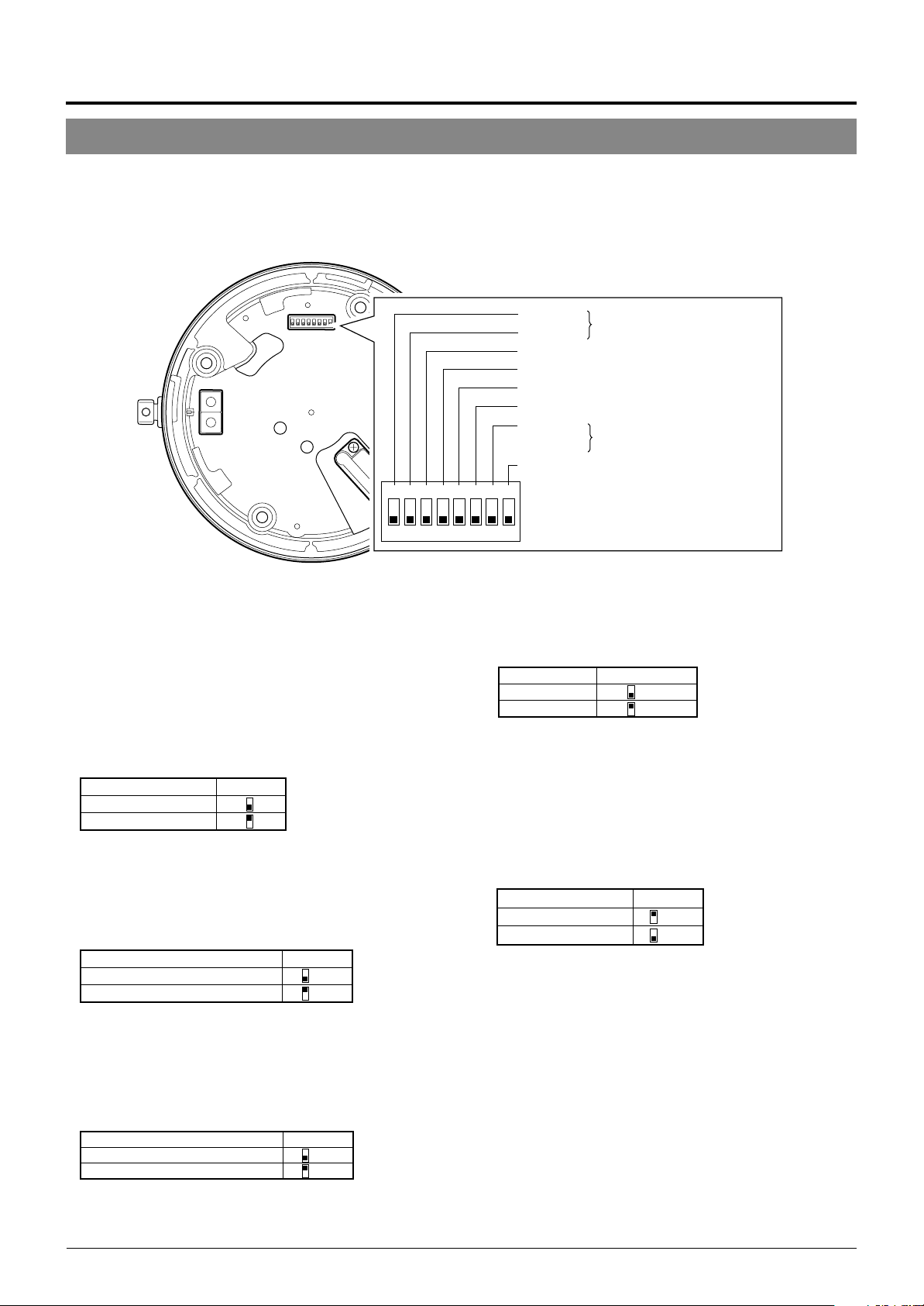
Anschlussherstellung und Installation
Schaltereinstellungen
Die Schaltereinstellungen am Deckenhalter müssen vor der Installation der Kamera vorgenommen werden.
Die Einstellungen schwanken je nach Systemkonfiguration.
Erforderliche Schaltereinstellungen
123
O
● Schalter 1, 2
Diese Schalter müssen auf “OFF” gestellt sein.
● DISP (Schalter 3)
Mit diesem Schalter kann die Anzeigefunktion für die
Monitormeldung “MANUAL” aktiviert/deaktiviert werden.
Diese Meldung bestätigt, dass die Kameraausrichtung
mittels einer Steuereinheit von Hand (auf eine andere als
die vorbestimmten Kamerapositionen) verändert wird.
Schalter 3MANUAL
Anzeige
Keine Anzeige
(Grundeinstellung: Aktivierte Anzeige)
● PROTOCOL (1) (Schalter 4)
Mit diesem Schalter kann zwischen Einzelkamera- und
Mehrfachkamera-Systemsteuerung umgeschaltet werden.
PROTOCOL(1) muss auf ON gestellt werden, wenn ein
Mehrfachkamera-System in Reihe geschaltet ist.
Schalter 4PROTOCOL (1)
Einzelkamera-System OFF
Mehrfachkamera-System (mit RM-P2580)
(Grundeinstellung: OFF)
ON
Im Mehrfachkamerabetrieb muss jeder Kamera eine Geräte-ID-
Nummer zugewiesen werden.
● PROTOCOL (2) (Schalter 5)
Entsprechend dem für die Kameras verwendeten
Steuerprotokoll den erforderlichen Einstellstatus wählen.
PROTOCOL (2)
Duplex (mitRM-P2580) OFF
Simplex ON
(Grundeinstellung: OFF)
Schalter 5
Schalter 1
Schalter 2
Reserviert. Dieser Schalter
muss auf „OFF“ gestellt sein.
Schalter 3 DISP
Schalter 4 PROTOCOL(1)
Schalter 5 PROTOCOL(2)
Schalter 6 SYNC
Schalter 7
Reserviert. Dieser Schalter
muss auf „OFF“ gestellt sein.
Switch 8 RX TERM
4
678
5
F
F
● SYNC (Schalter 6)
Im Einstellstatus ON ist das vertikale Syncsignal der Kamera
mit der Netzfrequenz verkoppelt.
SYNC Schalter 6
INT OFF
LL ON
(Grundeinstellung: OFF)
(LL-Modus: Nur für
50 Hz Netzfrequenz)
● Schalter 7
Dieser Schalter muss auf “OFF” gestellt bleiben.
● RX TERM (Schalter 8)
Mit diesem Schalter wird die Abschlussschaltung (110 Ω)
für die Steuersignalkontakte RX+ und RX– aktiviert/
deaktiviert.
RX-Abschlussschaltung
Abgeschlossen (110 Ω)
Open OFF
(Grundeinstellung: Abgeschlossen (110Ω)
Wird diese Kamera in einem Mehrfachkamera-System (RS485-System) eingesetzt, darf ausschließlich die am
Steuersignalkabel als letzte angeordnete Kamera
abgeschlossen werden. Für alle anderen Kameras muss
der Einstellstatus “Offen” (OFF) gelten.
Schalter 8
ON
G-12
Page 56

Erforderliche Schaltereinstellungen
3
2
4
1
5
0
6
7
Einerstelle
9
8
3
2
4
1
5
0
6
7
Zehnerstelle
9
8
● Geräte-ID
Wird diese Kamera in einem Mehrfachkamera-System
einschließlich Steuereinheit (wie RM-P2580) eingesetzt,
muss jeder Kamera eine Geräte-ID-Nummer zugewiesen
werden.
Dies ermöglicht die selektive Steuerung für die an RM-P2580
angeschlossenen Kameras. Die Geräte-ID-Nummer muss
jeweils mit der Nummer der VIDEO
INPUT-Anschlüsse von RM-P2580
übereinstimmen.
(Beispiel)
An der Kamera 1 (angeschlossen an
VIDEO INPUT 1) muss die Geräte-ID “0” und “1” wie rechts
gezeigt eingestellt werden.
“0”“1”
0
1
9
8
7
6
5
Zehnerstelle Einerstelle
9
2
8
3
7
4
DEUTSCH
MEMO
In einem Mehrfachkamera-System einschließlich Steuerpult RMP2580 sind die Kameras mittels eines Steuerkabels in Reihe
geschaltet. Dementsprechend ist das System bereits bei einer
inkorrekten Geräte-ID-Einstellung nicht mehr betriebsfähig.
<Überprüfung der Kamera-ID-Nummern>
1.
0
1
2
3
4
6
5
Das Monitorbild der zu überprüfenden Kamera aufrufen.
2.
Die Kamerastromversorgung (24 V Wechselstrom) ausund erneut einschalten.
3.
Die Kamera schaltet auf die Anfangskonfiguration, wobei
die folgenden Meldungen gezeigt werden:
PROCESSIN TIIAL
I--PNA:-I--TI TL:--
UPLEX I D- 10PROT OCLD
“DUPLEX” muss angezeigt
werden.
4.
Vergewissern Sie sich, dass “DUPLEX” und die ID-Num-
□□
mer
angezeigt werden und dass diese ID-Nummer
Die ID-Nummer □□ wird angezeigt.
Vergewissern Sie sich, dass diese
ID-Nummer korrekt ist.
korrekt ist, d.h. Mit der VIDEO INPUT-Nummer von RMP2580 übereinstimmt.
5.
Falls die ID-Nummer inkorrekt ist, die korrekte Nummer
eingeben.
G-13
Page 57

Maximale Kabellänge
100 m 260 m 410 m 500 m
Leiterdurchmesser (mm)
1,0 und dicker 1,6 und dicker 2,0 und dicker 2,6 und dicker
Anschlussherstellung und Installation
Kabelanschlüsse
An der Einbauposition muss eine runde.
1.
Einbauöffnung mit 90 mm Durchmesser
hergestellt werden.
90 mm Durchmesser
4.
Kabelanschluss.
Die am Deckenhalter anzubringenden Kabel sind wie
folgt: Stromversorgungskabel (24 Volt Wechselstrom),
Koaxialkabel, Steuersignalkabel und Alarmsignalkabel.
2.
Das Schutzgehäuse von dem Deckenhalter
abnehmen.
RELEASE
(ÖFFNEN)
Schutzgehäuse
Deckenhalter
3.
Die Kabel durch die Öffnung des Schutz-
(VERRIEGELN)
gehäuses führen.
Wie in der nachfolgenden Abbildung gezeigt zwei Schlitze in die Gummikappe schneiden und die von der Decke
kommenden Kabel durch diese aufgeschnittene Gummikappe führen.
LOCK
Steuersignalkabel
Alarmsignalkabel
Koaxialkabel
Stromversorgungskabel
An Steuereinheit
(wie RM-P2580)
An Alarmeingang
eines Alarmgebers etc.
An Monitor etc.
An Stromquelle mit
24 Volt Wechselstrom
Stromversorgungskabel (24 Volt Wechselstrom)
Dieses Kabel verbindet die 24 Volt Wechselstromquelle mit
dem 24 Volt Wechselstromeingang. Um fehlerhafte oder sich
lösende Anschlussverbindungen zu vermeiden, sollte zum
Anschluss an AC 24 V INPUT ein Kabelschuh verwendet
werden.
Bei Verwendung eines kunststoffisolierten 2-Leiter-Kabels
müssen die nachfolgend aufgelisteten Angaben zur maximal
zulässigen Kabellänge eingehalten werden. (Hierbei handelt
es sich um Näherungswerte.)
Gummikappe (oben)
Gummikappe (seitlich)
Kabelverschraubung
Maximaler Durchmesser 31 mm
Schutzschlauch
Maximaler Durchmesser
22 mm
Bis zu 33 mm
Spritzwasserfester Schutzschlauch
Der Durchmesser der Öffnung ohne Gummikappe beträgt
20,5 mm. Wird die Kamera an einer Position installiert, die
gelegentlich Spritzwasser ausgesetzt ist (z.B. unter einem
Dachvorspung), müssen die Kabel durch einen spritzwasserfesten Schutzschlauch geführt werden.
(Der Schutzschlauch muss der IP-52-Norm entsprechen.
Der maximale Durchmesser der Kabelverschraubung darf
31 mm betragen. )
Werden die Kabel seitlich zugeführt, Decken-Direkteinbauhalter WB-S573 verwenden. In diesem Fall darf die Länge
der Kabelverschraubung bis zu maximal 33 mm betragen. Der Schutzschlauchdurchmesser darf bis zu maximal 22 mm betragen.
VORSICHT
● Bei Verwendung eines dünnen Leitermaterials erhöht sich der
Kabelwiderstand. Dementsprechend fällt die effektive Spannung
ab, wenn die maximale Leistungsaufnahme erfolgt (z.B. bei
gleichzeitige durchgeführten Schwenk- und Neigebewegungen
aller Kameras).
Bei einem Spannungsabfall während des Kamerabetriebs
können Leistungseinbußen sowie verringerte Genauigkeit bei
der Einstellung auf vorbestimmte Position auftreten.
Um solche Probleme zu vermeiden, Leiter mit stärkerem Durchmesser oder kürzere Kabel verwenden, indem die Stromquelle
näher bei den Kameras positioniert wird. Wenn die
Nennstromstärke der Kamera am Kabel anliegt, sollte die
Spannung nicht unter 10 % fallen.
● Niemals ein für 24 Volt Wechselstrom ausgelegtes Kabel an
das Haushaltsnetz (230 V Wechselstrom) anschließen. Andernfalls kann das Gerät schwer beschädigt werden.
G-14
Page 58

Koaxialkabel
Bei Verwendung eines RG-59 Koaxialkabels.
Ein RG-11 Koaxialkabel kann nicht direkt
angeschlossen werden. Soll ein solches Kabel
verwendet werden, ein RG-59 Kabel an die Kamera
anschließen und mit dem RG-11 Kabel verbinden.
Das Koaxialkabelende muss wie nachfolgend gezeigt
vorbereitet werden.
Die Drahtummantelung nach hinten stülpen und mit Isolierband sichern,
damit diese sich nicht lösen und kein Kurzschluss entstehen kann.
Kunststoffmantel
7
(5)
Isolierband
Die eingeklammerten ( ) Abmessungen beziehen sich auf den
seitlichen Kabelanschluss im Schutzgehäuse. (Einheit: mm)
Wenn das Kabel verlängert wird, tritt verstärkt
Signaldämpfung auf, die Auflösung fällt ab und das
Bildrauschen erhöht sich. Falls eine Kabelverlängerung
erforderlich ist, einen größeren Leitungsdurchmesser
verwenden oder einen Kabellängenkompensator
zwischenschalten.
Wenn das Koaxialkabel durch die seitliche Kabelöffnung des
Schutzgehäuses geführt werden soll, muss die Ausrichtung
der Kabelklemme wie nachfolgend geändert werden.
DrahtummantelungLeiter
17
(12)
Mitgelieferte
Kabelklemme
Mitgelieferte Schraube
In der linken Abbildung
entfernte Schraube
Alarmsignalkabel
S. 6
☞
Alarmausgang (CN24)
Hier das mitgelieferte 4-polige
Alarmsignalkabel anschließen.
Alarm-Eingang/Ausgang (CN23)
Alarmeingang (CN26)
Hier das mitgelieferte 6-polige
Alarmsignalkabel anschließen.
Arbeitsweise des Alarmausgangs
N. OPEN
COM.
N. CLOSE
ALARM2+
oder
ALARM3+
22 Ω
ALARM2–
oder
ALARM3–
• ALARM 1 ist als Relais ausgelegt.
Im Alarmstatus wird der
Schließkontakt zwischen N.OPEN
und COM hergestellt und
gleichzeitig der Kontakt zwischen
N.CLOSE und COM. geöffnet.
Nennspannung
Max. angelegte Spannung: 30 V
Gleichstrom oder 24 V Wechselstrom.
Max. angelegte Stromstärke: 2 A
Kontaktlebensdauer: 200.000
• ALARM 2 und ALARM 3 sind als
Open-Collector-Ausgänge ausgelegt, wobei die Signale mittels
Photocoupler isoliert werden. Im
Alarmstatus ist der Ausgang
aktiviert.
Da diese Ausgänge als Plus- und
Minuspol ausgelegt sind, muss am
Pluspol eine höhere Spannung als
am Minuspol anliegen.
Keine Umkehrspannung anlegen.
Andernfalls werden diese Anschlüsse beschädigt.
DEUTSCH
Vorgänge
Steuersignalkabel
Steuerpult RM-P2580 ist für bis zu 8 Kameras ausgelegt,
wobei ein Satz von Steuersignalkabeln verwendet wird. Die
zulässige Gesamtlänge für diese Kabel beträgt 1200 Meter.
Kabel
Flachklingen
schraubendreher
Es können Kabel mit einer Dicke von 16 AWG bis 26 AWG
verwendet werden. Die Steuersignalkabel so anschließen, dass TX+
und TX– sowie RX+ und RX– jeweils ein Paar bilden.
4 mm
Um den Anschluss abzutrennen, die an
beiden Seiten befindlichen Schrauben wie
in der Abbildung gezeigt lösen.
Flachklingenschraubendreher
Vor dem Kabelanschluss den Isoliermantel
auf ca. 4 Millimeter Länge entfernen. Nach
der Anbringung aller Kabel die auf beiden
Seiten befindlichen Schrauben festziehen,
um den Anschluss zu sichern.
Die Verwendung eines zweifach verdrillten
(4 Leiter, 1 Paar) Kabels (0,65) wird
empfohlen. Andernfalls kann ein Kabel der
Kategorie 3 oder höher (wie für Ethernet
üblich) verwendet werden.
Nennspannung
Max. angelegte Spannung: 20 V
Gleichstrom
Maximale Treiber-Stromstärke: 25 mA
Arbeitsweise des Alarmeingangs
ALARM1
GND
• Mittels des Menüs kann festgelegt werden, ob der Alarmstatus bei geschlossenem oder geöffnetem Kontakt vorliegt.
• Das Alarmsignal muss für mindestens 200 ms anliegen. Wird
diese Mindestdauer unterschritten, kann das Alarmsignal ggf.
nicht identifiziert werden.
5.
Das Schutzgehäuse anbringen.
Attach the cover to the ceiling mount by reversing the Das
Schutzgehäuse am Deckenhalter anbringen. Hierbei in
umgekehrter Reihenfolge als bei Schritt 2 vorgehen.
• An den Alarmeingang muss ein
Erdungssignal angelegt werden,
um Störeinstreuungen in den internen elektrischen Schaltkreisen
zu vermeiden.
Keine Spannung anlegen!
G-15
Page 59

Anschlussherstellung & Installation
Installation des Deckenhalters
An Strebe oder Träger
Öse für
Sicherungsdraht
Deckenhalter
Gummidichtungen
(Vier auf jeder Seite)
1.
Einen Sicherungsdraht anbringen.
Einen Sicherungsdraht an dem Deckenhalter und einem
Deckenträger etc. anbringen, um ein Herunterfallen des
Halters zu verhindern. Zuerst den Sicherungsdraht durch
die Öse des Halters führen (siehe die linke Abbildung).
MEMO
● Den Sicherungsdraht so anbringen, dass er am Haltepunkt
(Deckenträger etc,) isoliert werden kann. Insbesondere wenn der
Draht ohne Isolation an metallischen Haltepunkten befestigt wird,
können Bildstörungen bei der Kamera verursacht werden.
● Darauf achten, dass der Sicherungsdraht und der Haltepunkt
(Deckenträger etc.) ausreichend stabil sind, um ein Herunterfallen
der Kamera zu verhindern
● Ein Sicherungsdraht gehört nicht zum Lieferumfang und kann im
Fachhandel bezogen werden.
2.
Den Deckenhalter an der Decke installieren.
Den Halter mit vier Schrauben an der Decke festschrauben (wie in der linken Abbildung gezeigt) und dabei
darauf achten, dass die Kabel nicht zwischen Halter und
Decke eingeklemmt werden. M4 Schrauben verwenden.
Werden Holzschrauben verwendet, muss der Schraubendurchmesser 4,1 mm betragen.
Schrauben
Installation der Kamera
Den Sicherungsdraht an
diesem Haken befestigen.
Sicherungsdraht
MEMO
● Die vier Schrauben einwandfrei festziehen. Andernfalls können
Staub und Feuchtigkeit durch die Schraubenöffnungen in das
Innere des Halters eindringen.
● Die Gummidichtungen für die Schraubenöffnungen des Decken-
halters dienen als Isolatoren, wenn die Decke aus einem
metallischen Material besteht, sowie als Wasserdichtungen. Wenn
der Deckenhalter in einer Decke aus einem metallischen Material
ohne ausreichende Isolation eingebaut wird, können Bildstörungen
bei der Kamera verursacht werden. Auf eine ausreichende Isolation
achten.
1.
Den Sicherungsdraht anbringen.
Den Sicherungsdraht der Kamera wie in der Abbildung
gezeigt am Haken des Deckenhalters befestigen.
Der Sicherungsdraht muss angebracht werden!
Andernfalls kann die Kamera nicht einwandfrei am
Deckenhalter angepasst werden. Keinen hohen Druck
ausüben. Andernfalls können Deckenhalter und
Kamera beschädigt werden.
G-16
VORSICHT
Unbedingt den Sicherungsdraht anbringen. Andernfalls kann die
Kamera herunterfallen.
Page 60

Deckenhalter
Kamera
Halteschraube
2.
Sicherstellen, dass die Halteschraube
gelöst ist.
Die Kamera kann nicht am Deckenhalter angebracht
werden, wenn die Halteschraube bereits festgezogen ist.
DEUTSCH
Kameraklemmbügel
Kameraklemmbügel
Die Kamera im
Uhrzeigersinn drehen.
3.
Die Kamera anpassen.
Die Position des Kameraklemmbügels und der Halteschraube überprüfen und die Kamera am Deckenhalter
anpassen.
4.
Die Kamera drehen.
Sicherstellen, dass die Kamera nicht schräg gehalten wird
und dann die Kamera im Uhrzeigersinn bis zum Anschlag
einschrauben. Der Kameraklemmbügel muss an der
Halteschraube anliegen.
Halteschraube
Die Halteschraube festziehen.
5.
Die Halteschraube festziehen.
Hierzu einen Kreuzschlitzschraubendreher verwenden.
VORSICHT
Falls diese Schraube nicht einwandfrei festgezogen wird, ist kein
fester Sitz der Kamera gewährleistet und die Kamera kann
herunterfallen. Die Halteschraube unbedingt einwandfrei festziehen.
* Soll die Kamera von der Decke abgenommen
1
werden, die Schritte
bis 5 in umgekehrter
Reihenfolge durchführen.
G-17
Page 61

Kamera-Setup mit Steuerpult RM-P2580
Setup-Bedienschritte
Bei der Verwendung von Steuerpult RM-P2580 können die zum Kamera-Setup erforderlichen Menüs auf dem angeschlossenen
Monitor dargestellt werden. (Bitte beziehen Sie sich auf die zum Steuerpult RM-P2580 gehörige Bedienungsanleitung.)
<Kameramenüeinstellungen mit RM-P2580>
MENU-Taste
SET-Taste
POWER-LED
SPEED
IRIS
FOCUS
AF
ZOOM
POWER
ALARM
KEY LOCK
OPEN
FAR
TELE CLEAR
CAMERA POSITION
CAMERA/POSITION
1
2
3
4
5
6
7
8
9
0
ENTER
/HOME
CAMERA
OPTION1OPTION
AUTO
PAN
SETUP
MENU SET
CLOSE
NEAR
WIDE
Cursor
POSITION SETUP. .
CAMER A . .
CONTROL UN I T . .
SETUP
Steuerpult-SETUP-Menü
CAM . FUNC T I ON . .
CAM. T I T L E / AL ARM. .
CAM. V I DEO ADJUST . .
CAM. ALC / Ex DR . .
HOME MOT I ON D ET ECT . .
AUTO PAN / PATROL / TRACE. .
POS I . FUNCT I ON SE T . .
FACTORY SETT I NGS . .
–––M E N U –––
Hauptschalter
(Rückseite)
REMOTE CONTROL UNIT
AUTO F-1 F-2 F-3
PAN/TILTLENS
POSITION
2
AUTO
PATROL
RM-P2580
PAN/TILT-Regler
Verweis auf
Untermenüs
1.
Am RM-P2580 den an der Rückseite befindlichen
Hauptschalter auf ON stellen.
Die POWER-LED leuchtet.
2.
Die MENU-Taste für 3 Sekunden gedrückt halten.
• Die Menü-Tasten-LED leuchtet auf.
• Auf dem an MONITOR OUTPUT-1 angeschlossenen Monitor wird
das Steuerpult-SETUP-Menü gezeigt.
3.
Mit dem PAN/TILT-Regler den Menü-Cursor (>) neben
“CAMERA” setzen.
• Durch Umlegen des PAN/TILT-Reglers nach oben () wird der
Cursor nach oben versetzt.
• Durch Umlegen des PAN/TILT-Reglers nach unten () wird der
Cursor nach unten versetzt.
4.
Die SET-Taste drücken.
• Das Kamera-Menü (MENU) wird gezeigt.
• Menüeinträge, die mit zwei Punktzeichen enden, enthalten Unter-
menüs.
5.
Den PAN/TILT-Regler nach oben oder unten umlegen, um einen Menüeintrag wählen.
Kamera-SETUP-Menü
Änderungszeichen
–––CAMERA FUNC T I ON –––
POS.TITLE LOC. UP-L
FLIP DIGITAL
VAR.P/T SPEED ON
EASY AF OFF
D.ZOOM MAX X2
PRI VATE MASK. .
Beispiel für ein Untermenü
G-18
6.
Den PAN/TILT-Regler nach links oder rechts umlegen, um eine andere Einstelloption zu wählen.
• Durch Umlegen des PAN/TILT-Reglers nach links () wird der
Einstellwert verringert.
• Durch Umlegen des PAN/TILT-Reglers nach rechts () wird der
Einstellwert erhöht.
7.
Die MENU-Taste drücken.
Nach der Durchführung aller Einstellungen die MENU-Taste drücken,
um das zuvor gezeigte Menü aufzurufen.
Page 62

Menüaufbau
Die Menüs sind wie unten gezeigt hierarchisch strukturiert. Die einzelnen Menüeinträge werden jeweils auf der angezeigten Seite erläutert.
Normale Bildschirmanzeige
S.20
☞
POS I T I ON SETUP . .
CAMERA. .
CONT ROL UN I T . .
SETUP
Steuerpult-SETUP-Menü
––– M E N U – ––
CAM. FUNCT I ON . .
CAM. T ITLE/ ALARM. .
CAM. V I DEO AD JUST . .
CAM. ALC / E xDR . .
HOME MOT I ON DETE CT . .
AUTO PAN / PATROL/ TRACE . .
POS I . FUNCT I ON S ET . .
FACTORY SETT I NGS. .
c
Hauptmenü (MENU)
• Die folgenden Einstellmenüs
können aufgerufen werden:
CAM. FUNCTION
CAM. TITLE/ALARM
CAM. VIDEO ADJUST
CAM.ALC/ExDR
AUTO PAN/PATROL/TRACE
• Menü zur Einstellung des
Bewegungssensormodus:
HOME MOTION DETECT
• Menü zur Einstellung der
Kamerafunktionen für vorbestimmte
Positionen:
POSI. FUNCTION SET
––CAMERA F UNCT I ON – –
V.PHASE 0
POS . T I T L E LOC . UP - L
FLIP DIGITAL
VAR. P / T SPEED ON
EASY AF OFF
D.ZOOM MAX X2
PRIVATE MASK. .
CAMERA FUNCTION-Menü
S.23
☞
–––CAMERA V I DEO ADJ UST –––
COLOUR LEVE L NORMAL
ENHANCE LE VE L NORMA L
PEDESTAL LEVE L NORMAL
AUTO B LK . CT L . OFF
CAMERA VIDEO ADJUST-Menü
S.26
☞
–––HOME MOT I ON DE T EC T – ––
MOD E OF F
LEV EL NORMAL
AREA EDI T . .
ALARM D I SPLAY 5s
DEMONSTRAT I ON . .
HOME MOTION DETECT-Menü
S.28
☞
––POSITION FUNCTION SET – –
POSITION TITLE..
I R I S MODE AUTO
BLC OFF
W.BALANCE ATW
R-B GAIN –––
M-G GAIN –––
S.21
☞
–––CAMERA T I TLE / A LARM
CAM.TITLE EDIT. .
AREA T I TL E OFF
AREA TITLE EDIT..
ALM . T I T L E S I ZE DOU BLE
ALM.T I TLE COLOUR WHI TE
ALARM T I TLE ED I T . .
AL ARM I NPUT . .
ALARM OUTPUT . .
–––
CAMERA TITLE/ALARM-Menü
S.23
☞
–––CAMERA A LC / Ex DR
AVERAGE : PEAK 8 : 2
SHUTTER 1 / 50
AGC MODE 10 dB
SENSE UP OFF
PR I OR I TY MOT I ON
Ex DR MODE OF F
ExDR LEVEL –––
B&W / COLOUR MODE . .
–––
CAMERA ALC/ExDR-Menü
S.27
☞
––AUTO PAN / PATROL / TRACE
AUTO PAN MODE RE TURN
AUTO PAN SPEED NORMAL
A . PAN START POS . SET . .
A.PAN RETURN POS.SET. .
AUTO PA TROL SET . .
AUTO TRACE SE T . .
RM. A . PAN KEY A . PAN
RM. A . PA TROL KEY A. PATROL
––
AUTO PAN/PAYTOL/TRACE-Menü
S.28
☞
DEUTSCH
POSIITION FUNCTION SET-Menü
––FACTOR Y SE T T I NGS – –
CANCEL
CLEAR(W/ O POSI . T ITLE )
CLEAR( AL L )
FACTORY SETTINGS-Menü
G-19
Page 63

Kamera-Setup mit Steuerpult RM-P2580
CAMERA FUNCTION-Menü
Dieses Menü dient zur Einstellung von Kamerafunktionen.
Eintrag
V.PHASE
POS. TITLE LOC.
FLIP
VAR. P/T SPEED
Funktion & Einstellungen
Zum Abgleich des V-Syncsignals auf weitere zum System gehörigen Kameras, wenn der am
Deckenhalter Syncwahlschalter auf LL gestellt ist. (Nur für Stromnetze mit 50 Hz.)
Wenn der Einstellstatus LL nicht vorliegt, erscheint die Anzeige “- - -” zur Bestätigung, dass
keine Einstellung vorgenommen werden kann.
Verfügbare Einstelloptionen : –156 bis 0 bis 156
Zur Einstellung der Anzeigeposition für den Positions- und Segmenttitel auf dem Monitor.
UP : Anzeige im oberen Bildschirmbereich.
DOWN : Anzeige im unteren Bildschirmbereich.
L : Anzeige im linken Bildschirmbereich.
C : Anzeige im mittleren Bildschirmbereich.
R : Anzeige im rechten Bildschirmbereich.
Verfügbare Einstelloptionen : UP-L, UP-C, UP-R, DOWN-L, DOWN-C, DOWN-R
Im Einstellstatus OFF wird ein Neigevorgang durchgeführt, bis die Kamera senkrecht
nach unten weist. Wird direkt unterhalb der Kamera eine Bewegung erfasst, führt
die Kamera drei Richtvorgänge durch:
Schwenkung um 180° 3 Neigung nach oben.
Mittels der FLIP-Funktion wird dieser Ablauf beschränkt. Diese Funktion verwenden,
wenn sich direkt unter der Kamera befindliche Objekte überwacht werden sollen.
OFF : Die FLIP-Funktion ist deaktiviert.
DIGITAL : Erreicht die Kamera nach der senkrecht nach unten weisenden
Ausrichtung einen Neigungswinkel von 135°, wird das Bild entlang der
senkrechten und waagerechten Achse umgekehrt.
AUTO : Erreicht die Kamera die senkrecht nach unten weisende Richtposition,
erfolgt ein Schwenkvorgang um 180° und Stopp.
Dient zur Aktivierung/Deaktivierung der automatischen Steuerung von Schwenkund Neigegeschwindigkeit in Abhängigkeit von der Brennweite. Zoomen in Richtung
TELE verlangsamt die Schwenk- und Neigegeschwindigkeit.
Zoomen in Richtung WIDE beschleunigt die Schwenk- und Neigegeschwindigkeit.
Verwenden, wenn mit unterschiedlicher Brennweite überwacht wird.
OFF : Deaktivierte Funktion.
ON : Aktivierte Funktion.
Neigung senkrecht nach unten
1
2
Grundeinstellung
0
UP-L
DIGITAL
ON
EASY AF
D. ZOOM MAX
PRIVATE MASK..
Bei aktivierter Funktion (ON) wird der Autofokus (AF) automatisch aktiviert, wenn
die Schwenk- und Neigefunktion sowie der Zoom manuell gesteuert werden.
Diese Funktion erleichtert die Bedienung im Falle einer häufigen manuellen
Bedienung, da die Schärfe nach einem manuellen Bedienvorgang nicht jedesmal
von Hand neu eingestellt werden muss.
OFF : Deaktivierte Funktion.
ON : Aktivierte Funktion.
MEMO
Mit dem Autofokus kann in bestimmten Fällen keine einwandfreie Scharfstellung erzielt
werden. (☞ S. 4)
In diesem Fall muss manuell scharfgestellt werden.
Beim Einzoomen (in Richtung TELE) wird zuerst der optische und dann der
elektronische Zoom aktiviert. Mittels dieser Funktion kann das elektronische
Zoomverhältnis eingestellt werden.
Verfügbare Einstelloptionen : x1, x2, x4, x6, x8, x10
MEMO
● Beim elektronischen Zoomen wird das Bildsignal digital bearbeitet; dies kann zu Beein-
trächtigungen der Bildqualität führen.
● Wenn ein größeres elektronisches Zoomverhältnis verwendet wird, kann sich die Bild-
mitte leicht nach links oben verschieben. Dies ist konstruktionsbedingt und stellt keine
Fehlfunktion dar.
● Der Übergang wischen optischem und elektronischem Zoom erfolgt nicht kontinuierlich.
Bei Erreichen der maximalen optischen Zoomposition (TELE) muss nochmals die TELETaste gedrückt werden.
Dient zur Abschirmung von erfassten Bildbereichen, die nicht gezeigt werden sollen.
Die Maske (grau markierte Bildfläche) wird bei Veränderungen der Kameraposition
oder des Bildausschnitts beim Zoomen automatisch wie erforderlich versetzt.
S.29, “PRIVAT MASK-Einstellungen”
☞
OFF
x2
–
G-20
Page 64

CAMERA TITLE/ALARM-Menü
Dieses Menü dient zur Einstellung von Titel- und Alarmfunktionen.
Eintrag
CAM. TITLE EDIT
AREA TITLE
AREA TITLE EDIT
ALM. TITLE SIZE
ALM. TITLE COLOUR
ALARM TITLE EDIT
ALARM INPUT
Funktion & Einstellungen
..
Dient zur Erstellung des ständig links unten im Bild eingeblendeten Titels.
Ein Titel darf bis zu 16 alphanummerische Zeichen enthalten.
S. 30, “CAMERA TITLE-Einstellungen”
☞
Der Schwenkbereich von 360° kann in 16 Segmente unterteilt werden. Jedem
Segment kann ein Titel zugewiesen werden, der bis zu 16 alphanummerische
Zeichen enthalten darf. Beim manuellen Schwenken der Kamera werden diese Titel
angezeigt. Diese Funktion dient zur Aktivierung/Deaktivierung der Titelfunktion.
ON : Aktivierte Titelfunktion.
OFF : Deaktivierte Titelfunktion.
..
Dient zur Einstellung der Segmenttitel.
S. 31, “AREA TITLE-Einstellungen”
☞
Dient zur Einstellung der Zeichengröße für die Alarmtitel (die Anzeige erfolgt bei
Alarmauslösung).
NORMAL : Gleiche Zeichengröße wie für die Menüanzeigen.
DOUBLE : Horizontal und vertikal verdoppelte Zeichengröße (im Vergleich zu den
Dient zur Einstellung der Zeichenfarbe der Alarmtitel.
Verfügbare Einstelloptionen: WHITE (Weiß), YELLOW (gelb), CYAN (blau), GREEN (grün)
..
Dient zur Einstellung der Alarmtitel.
S. 32, “ALARM TITLE-Einstellungen”
☞
..
Dient zur Konfiguration der am Deckenhalter befindlichen Alarmeingänge. Das Bildsignal
kann wahlweise auf Schwarzweiß geschaltet werden, wenn ein Alarm anliegt.
S. 25 Eintrag “B&W”
☞
Menüanzeigen).
MEMO
● Wenn für “B&W” der Einstellstatus 1 bis 4 gilt, erscheint die Anzeige [B&W] bei den
entsprechenden Einträgen ALARM IN 1 bis 4. Die Einstellung kann nicht geändert werden.
● Wenn für ALARM IN 1 bis 4 die Positionseinstellungen POS 64 bis POS 99 gelten, erfolgt
keine Rückstellung auf die vorbestimmte Position, selbst wenn ein Alarmsignal anliegt.
Grundeinstellung
–
OFF
DEUTSCH
–
DOUBLE
WHITE
–
–
ALARM IN1
ALARM IN2
ALARM IN3
ALARM IN4
Dient zur Einstellung der Kameraposition bei Alarm 1. Wenn am Alarmeingang 1
ein Alarmsignal anliegt, wechselt die Kamera automatisch auf diese vorbestimmte
Position.
HOME bedeutet die Grundposition und POSI1 bedeutet Position 1.
Verfügbare Einstelloptionen: OFF, HOME, POSI 1 bis POSI 99.
Dient zur Einstellung der Kameraposition bei Alarm 2. Wenn am Alarmeingang 2
ein Alarmsignal anliegt, wechselt die Kamera automatisch auf diese vorbestimmte
Position.
HOME bedeutet die Grundposition und POSI1 bedeutet Position 1.
Verfügbare Einstelloptionen: OFF, HOME, POSI 1 bis POSI 99.
Dient zur Einstellung der Kameraposition bei Alarm 3. Wenn am Alarmeingang 3
ein Alarmsignal anliegt, wechselt die Kamera automatisch auf diese vorbestimmte
Position.
HOME bedeutet die Grundposition und POSI1 bedeutet Position 1.
Verfügbare Einstelloptionen: OFF, HOME, POSI 1 bis POSI 99.
Dient zur Einstellung der Kameraposition bei Alarm 4. Wenn am Alarmeingang 4
ein Alarmsignal anliegt, wechselt die Kamera automatisch auf diese vorbestimmte
Position.
HOME bedeutet die Grundposition und POSI1 bedeutet Position 1.
Verfügbare Einstelloptionen: OFF, HOME, POSI 1 bis POSI 99.
OFF
OFF
OFF
OFF
G-21
Page 65

Kamera-Setup mit Steuerpult RM-P2580
CAMERA TITLE/ALARM-Menü (FORTS.)
Eintrag
ALARM INPUT
POLARITY
DURATION
PRIORITY
Funktion & Einstellungen
..
(Fortsetzung)
Dient zur Einstellung der Polarität des Alarmeingangssignals.
MAKE : Alarmsignal liegt bei geschlossenem Kontakt vor.
BREAK : Alarmsignal liegt bei offenem Kontakt vor.
MEMO
Wird ein Eintrag im B&W-Modus für Alarm 1 bis 4 eingestellt, wird der MAKE-Modus gewählt,
selbst wenn “BREAK” angezeigt wird.
Dient zur Einstellung der Alarmdauer ab dem Zeitpunkt der Alarmauslösung (Einheit: Sekunden)
Verfügbare Einstelloptionen :
5 s, 6 s, 7 s, 8 s, 9 s, 10 s, 15 s, 20 s, 30 s oder 60 s.
VORSICHT
Dieser Eintrag ist ungültig, wenn Steuerpult RM-P2580 verwendet wird. Bei Verwendung
von RM-P2580 muss der Eintrag “ALARM TIME” verwendet werden.
Dient zur Aktivierung/Deaktivierung der Steuermoduspriorität (automatisch oder
manuell), wenn im manuellen Modus ein Alarm ausgelöst wird.
ALARM : Bei angelegtem Alarmsignal kann die Kamera nicht manuell bedient
MANUAL : Bei angelegtem Alarmsignal kann die Kamera weiterhin manuell
werden (Alarmvorrang).
bedient werden (Steuermodusvorrang).
VORSICHT
Dieser Eintrag ist ungültig, wenn Steuerpult RM-P2580 verwendet wird. Bei Verwendung
von RM-P2580 besteht stets ALARM-Vorrang.
Grundeinstellung
MAKE
5s
ALARM
ALARM OUTPUT
ALARM OUT1
ALARM OUT2
ALARM OUT3
..
Dient zur Konfiguration der am Deckenhalter befindlichen Alarmausgänge.
Dient zur Konfiguration von Alarmausgang 1.
OFF : Es erfolgt keine Alarmsignalabgabe.
ALARM : Die Alarmsignalabgabe erfolgt bei Alarmauslösung (Bewegungssensor oder
B&W : Die Alarmsignalabgabe erfolgt bei Umschaltung auf den Schwarzweißmodus.
PRESET : Die Alarmsignalabgabe erfolgt bei Rückstellung auf eine vorbestimmte Position.
AUX 1 bis 3 : Die Alarmsignalabgabe erfolgt, wenn das entsprechende AUX-Signal angelegt
Alarmeingang).
wird. (Dieses Signal wird in Abhängigkeit von der verwendeten Steuereinheit
definiert.)
MEMO
● Da ALARM OUT 1 über ein mechanisches Relais geschaltet ist, kann das Schaltgeräusch
je nach Umgebungsgeräuschpegel ggf. unerwünscht sein. In diesem Fall ALARM OUT 2
oder 3 verwenden.
● Da ALARM OUT 1 über ein mechanisches Relais geschaltet ist, kann sich die Lebens-
dauer des Relais verkürzen, wenn die Alarmsignalabgabe (nach Alarmauslösung durch
Bewegungssensor oder Alarmeingang) häufig erfolgt. Die Relaislebensdauer beträgt ca.
200.000 Schaltvorgänge. Das Relais ist ein Abnutzungsbauteil und entsprechend wird ein
Teiletausch auch vor Ablauf der Garantiezeit des Geräts in Rechnung gestellt.
Dient zur Konfiguration von Alarmausgang 2.
OFF : Es erfolgt keine Alarmsignalabgabe.
ALARM : Die Alarmsignalabgabe erfolgt bei Alarmauslösung (Bewegungssensor oder
B&W : Die Alarmsignalabgabe erfolgt bei Umschaltung auf den Schwarzweißmodus.
PRESET : Die Alarmsignalabgabe erfolgt bei Rückstellung auf eine vorbestimmte Position.
AUX 1 bis 3: Die Alarmsignalabgabe erfolgt, wenn das entsprechende AUX-Signal angelegt
Dient zur Konfiguration von Alarmausgang 3.
OFF : Es erfolgt keine Alarmsignalabgabe.
ALARM : Die Alarmsignalabgabe erfolgt bei Alarmauslösung (Bewegungssensor oder
B&W : Die Alarmsignalabgabe erfolgt bei Umschaltung auf den Schwarzweißmodus.
PRESET : Die Alarmsignalabgabe erfolgt bei Rückstellung auf eine vorbestimmte Position.
AUX 1 bis 3: Die Alarmsignalabgabe erfolgt, wenn das entsprechende AUX-Signal angelegt
Alarmeingang).
wird. (Dieses Signal wird in Abhängigkeit von der verwendeten Steuereinheit
definiert.)
Alarmeingang).
wird. (Dieses Signal wird in Abhängigkeit von der verwendeten Steuereinheit
definiert.)
–
ALARM
ALARM
ALARM
G-22
Page 66

CAMERA VIDEO ADJUSTMENT-Menü
Dieses Menü dient zur Einstellung von Kamerafunktionen, wie Farbpegel, Konturenverstärkung etc.
Eintrag
COLOUR LEVEL
ENHANCE LEVEL
PEDESTAL LEVEL
AUTO BLK. CTL
Dient zur Einstellung des Farbpegels.
Pegelerhöhung : Einen kleineren Wert wählen.
Pegeleabsenkung : Einen größeren Wert wählen.
Verfügbare Einstelloptionen: –5 bis NORMAL bis 5.
Dient zur Einstellung der Konturenverstärkung, d.h. zur Einstellung der bevorzugten
Bildschärfe.
Weicheres Bild : Einen kleineren Wert wählen.
Schärferes Bild : Einen größeren Wert wählen.
Verfügbare Einstelloptionen: –5 bis NORMAL bis 5.
Dient zur Einstellung des Schwarzpegels des Videosignals.
Dunkleres Bild : Einen kleineren Wert wählen.
Helleres Bild : Einen größeren Wert wählen.
Verfügbare Einstelloptionen : –5 bis NORMAL bis 5.
Diese Funktion sollte aktiviert werden, wenn selbst bei automatischer Pegelanhebung(AGC:
Auto Gain Control) dunkle Bildbereich nicht deutlich erkennbar sind.
ON : Aktivierte Funktion — der Schwarzpegel des Videosignals wird automatisch
verstärkt, damit dunkle Bildbereiche besser erkennbar abgebildet werden
können.
OFF : Deaktivierte Funktion.
Funktion & Einstellungen
CAMERA ALC/ExDR-Menü
Dieses Menü dient zur Einstellung von Funktionen zur automatischen Korrektur der Bildhelligkeit.
Grundeinstellung
NORMAL
NORMAL
NORMAL
OFF
DEUTSCH
Eintrag
AVERAGE : PEAK
SHUTTER
Funktion & Einstellungen
Dient zur Einstellung der Belichtungsmessung unter Bezugnahme auf das Verhältnis
von Spitzen- zu Durchschnittswert.
Hoher Durchschnittswert
Hoher Spitzenwert : Empfohlen, wenn beleuchtete Bereiche überstrahlt
Verfügbare Einstelloptionen : 10:0, 9:1, 8:2, 6:4, 5:5
Dient zur Einstellungen der elektronischen Verschlusszeit.
Wenn für “SENSE UP” eine Einstelloption von “x2” oder höher gilt, sind die
verfügbaren SHUTTER-Einstelloptionen auf 1/50 und 1/120 beschränkt.
Wenn für “ExDR MODE” die Einstelloption “ON” gilt, sind die verfügbaren SHUT-
TER-Einstelloptionen auf 1/50 und 1/120 beschränkt.
Verfügbare Einstelloptionen : 1/50, 1/120, 1/250, 1/500, 1/1000, 1/2000, 1/4000,
: Empfohlen, wenn nicht beleuchtete Bereiche zu
abgebildet werden. (Beispiel: 10:0).
werden. (Beispiel: 5:5)
1/10000
MEMO
Wenn bei Betrieb unter Leuchtstoffkörperbeleuchtung Flackerstörungen auftreten, eine
●
Verschlusszeit von 1/50 (bei 50 Hz Netzfrequenz) oder 1/120 (bei 60 Hz Netzfrequenz)
wählen.
● Bei schnellen Verschlusszeiten können über und unter punktförmigen Leuchtquellen
senkrechte weiße Streifen im Bild auftreten. Dies ist bei CCD-Bildwandlern konstruktionsbedingt und stellt keine Fehlfunktion dar.
Grundeinstellung
8:2
1/50
G-23
Page 67

Kamera-Setup mit Steuerpult RM-P2580
CAMERA ALC/EXDR-Menü (FORTS.)
Eintrag
AGC MODE
SENSE UP
Funktion & Einstellungen
Dient zur Einstellung des maximalen AGC-Pegels (Auto Gain Control) zur
elektronischen Pegelanhebung bei geringer Umgebungshelligkeit.
OFF : Deaktivierter AGC-Modus.
10 dB : Je nach Umgebungshelligkeit erfolgt die Pegelanhebung um bis zu 10 dB.
20 dB : Je nach Umgebungshelligkeit erfolgt die Pegelanhebung um bis zu 20 dB.
SUPER : Verwenden, wenn selbst mittels der Einstelloption “20 dB” noch keine
ausreichende elektronische Aufhellung erzielt wird.
MEMO
Wenn für “B&W” der Einstellstatus “AUTO” gilt, erfolgt die Anzeige [SUPER] bei auf “SU-
●
PER” eingestelltem “AGC MODE” und die Anzeige [20 dB] für die anderen Einstellungen.
Die Pegelanhebung erfolgt bis zu dem Pegel, der für den angezeigten Modus verfügbar ist.
● Bei aktivierter Pegelanhebung tritt zunehmend Bildrauschen auf.
● Im Einstellstatus “SUPER” kann die AGC-Funktionsausführung verzögert erfolgen, wenn
ein Angleich an eine plötzliche starke Änderung des Umgebungshelligkeitspegels
erforderlich wird.
Dient zur Empfindlichkeitserhöhung durch die Verlängerung der Belichtungszeit. Es kann
vorbestimmt werden, um zu welchem Faktor die Empfindlichkeit bei geringer Objekthelligkeit
automatisch erhöht wird. Im Einstellstatus “x32” wird die Empfindlichkeit entsprechend
kontinuierlich um bis das 32-fache (im Vergleich zum Standardpegel) erhöht.
Bei Erhöhung der Empfindlichkeit wählt die Kamera eine längere Verschlusszeit, so dass
erfasste Bewegungsabläufe ggf. unnatürlich wirken. Wenn für “SHUTTER” eine Verschlusszeit
von 1/250 oder kürzer eingestellt ist, ist dieser Modus nicht verfügbar und anstelle des
Menüeintrags “SENSE UP” wird im CAMERA ALC/ExDR-Menü das Symbol “---” gezeigt.
Verfügbare Einstelloptionen : OFF, x2, x4, x8, x16, x24, x32
MEMO
● Wird eine hohe Empfindlichkeitserhöhung für SENSE UP gewählt, können eine grob-
körnige Bildqualität sowie Überbelichtung auftreten. Dies ist keine Fehlfunktion.
● Wenn für die SENSE UP--Funktion nicht der Einstellstatus OFF gilt, kann bei der Ein-
wirkung von Leuchtstoff- oder Quecksilberlampen Bildflackern auftreten. Dies ist konstruktionsbedingt und stellt keine Fehlfunktion dar.
Gegebenenfalls können Flackerstörungen auch unter den folgenden Bedingungen nicht
reduziert werden: 1) Wenn die Verschlusszeit auf 1/120 eingestellt ist und die Netzfrequenz 50 Hz beträgt. 2) Wenn die Verschlusszeit auf 1/50 eingestellt ist und die Netzfrequenz 60 Hz beträgt.
Grundeinstellung
10 dB
OFF
PRIORITY
ExDR MODE
Es kann vorbestimmt werden, ob bei der Bildüberwachung die Kamerabewegung oder
die Bildqualität Vorrang haben, wenn ein Objekt nicht ausreichend hell abgebildet wird.
MOTION : Die Kamerabewegung hat Vorrang. Bei dunklen Objekten hat der AGC-
Modus Vorrang. Diese Einstellung empfiehlt sich für sich schnell
bewegende Objekte.
PICTURE : Die Bildqualität hat Vorrang. Bei dunklen Objekten hat der SENSE UP-
Modus Vorrang. Diese Einstellung empfiehlt sich, wenn ein möglichst
hohe Bildqualität erforderlich ist.
MEMO
● Gilt sowohl für “AGC MODE” als auch “SENSE UP” der Einstellstatus “OFF“, ist diese
Funktion nicht verfügbar und anstelle dieses Eintrags wird im CAMERA ALC/ExDRMenü das Symbol “---” gezeigt.
● Wenn für “B&W” der Einstellstatus “AUTO” gilt, ist “PRIORITY” auf “MOTION” eingestellt
und es erfolgt die Anzeige “---”.
Dient zur Aktivierung/Deaktivierung der ExDR-Funktion zur Bearbeitung von Bildern,
die Objekte mit hohen Helligkeitsunterschieden enthalten, um eine besser
erkennbare Abbildung zu erzielen, wenn diese Objekte mit einer Verschlusszeit
von 1/120 oder kürzer erfasst werden.
Wenn für “SHUTTER” eine Verschlusszeit von 1/250 oder kürzer eingestellt ist, ist
dieser Modus nicht verfügbar und anstelle des Menüeintrags “SENSE UP” wird im
CAMERA ALC/ExDR-Menü das Symbol “---” gezeigt.
OFF : Deaktivierte Funktion.
ON : Aktivierte Funktion.
MEMO
● Wenn für die ExDR-Funktion der Einstellstatus ON gilt, kann bei der Einwirkung von
Leuchtstoff- oder Quecksilberlampen Bildflackern auftreten. Dies ist konstruktionsbedingt und stellt keine Fehlfunktion dar.
● Gegebenenfalls können Flackerstörungen auch unter den folgenden Bedingungen nicht
reduziert werden: 1) Wenn die Verschlusszeit auf 1/120 eingestellt ist und die Netzfrequenz 50 Hz beträgt. 2) Wenn die Verschlusszeit auf 1/50 eingestellt ist und die Netzfrequenz 60 Hz beträgt.
MOTION
OFF
G-24
Page 68

Eintrag
Funktion & Einstellungen
Grundeinstellung
ExDR LEVEL
B&W/COLOUR
...
MODE
B&W
Dient zur Einstellung des Helligkeitspegels im ExDR-Modus, so dass vom Benutzer
zu definierenden Objektbereiche in der bestmöglichen Erkennbarkeit gezeigt werden
können.
Wenn ein dunkler Objektbereich deutlich erkennbar sein soll: Den Pegel erhöhen.
Wenn ein heller Objektbereich deutlich erkennbar sein soll: Den Pegel verringern.
Verfügbare Einstelloptionen : –5 bis NORMAL bis 5
MEMO
● Wenn das Objekt oder verschiedene Objekte starke Helligkeitsunterschiede aufweisen,
kann ggf. keine verbesserte Erkennbarkeit durch die Variierung des ExDR LEVEL-Pegels
erzielt werden.
● Wenn für “SHUTTER” eine Verschlusszeit von 1/250 oder kürzer eingestellt ist, wird das
Symbol “---” gezeigt und die für “Ex DR LEVEL” vorgenommene Einstellung wird nicht
ausgeführt.
● Wenn für “Ex DRIVE MODE” der Einstellstatus “OFF” gilt, kann für “Ex DR LEVEL” keine
Einstellung vorgenommen werden.
Dient zur Umschaltung zwischen Farb- und Schwarzweißmodus.
Wenn die Umschaltung zwischen Farb- und Schwarzweißmodus ausgeführt wird,
kann sich die Scharfstellung verschieben. In diesem Fall muss erneut scharf gestellt
werden.
Dient zur Umschaltung zwischen Farb- und Schwarzweißmodus.
OFF : Deaktivierter Schwarzweißumschaltmodus.
ON : Aktivierter kontinuierlicher Schwarzweißmodus.
AUTO : Automatische Umschaltung auf den Farbmodus (bei ausreichender
Objektbelichtung) oder auf den Schwarzweißmodus (bei
unzureichender Objektbelichtung).
ALARM IN 1 bis 4:Die Kamera schaltet automatisch auf den Schwarzweißmodus, sobald
ein Alarmsignal an den Alarmeingängen 1 bis 4 anliegt.
Der Schwarzweißmodus wird aktiviert (ON), wenn der Kontakt
geschlossen wird, und deaktiviert (OFF), wenn der Kontakt offen ist.
MEMO
● Zur Gewährleistung der Umschaltung zwischen Farb- und Schwarzweißmodus:
Wenn für “B&W” der Einstellstatus “AUTO” gilt, erfolgt die Umschaltung in Abhängigkeit
von der Objekthelligkeit. Je nach Bildwinkel und/oder Umgebungslicht kann diese Umschaltung jedoch ggf. unterbleiben.
Um eine Umschaltung sicherzustellen, sollte benutzerseitig ein Alarmsensor (nicht mitgeliefert) installiert und mit einem der Alarmeingänge der Kamera verbunden werden,
so dass die Umschaltung zwischen Farb- und Schwarzweißmodus alarmsignalgesteuert
erfolgt.
● Unter Infrarotbeleuchtung sollte für "B&W" nicht der Einstellstatus "AUTO" gewählt wer-
den, um Einfärbungen zu vermeiden.
NORMAL
DEUTSCH
OFF
LEVEL
LIGHT TYPE
Wenn für “B&W” der Einstellstatus “AUTO” gilt, kann mit dieser Funktion bestimmt
werden, bei welchem Belichtungspegel die Kamera automatisch auf den
Schwarzweißmodus umschaltet.
LOW : Die Kamera wechselt auf den Schwarzweißmodus, wenn das Objekt
einen niedrigen Helligkeitspegel vorweist.
NORMAL : Die Kamera wechselt auf den Schwarzweißmodus, wenn das Objekt
einen normalen Helligkeitspegel vorweist.
HIGH : Die Kamera wechselt auf den Schwarzweißmodus, wenn das Objekt
einen hohen Helligkeitspegel vorweist.
MEMO
Wenn für “B&W” ein anderer Modus als “AUTO‘ eingestellt ist, wird das Symbol “---” gezeigt
und für “LEVEL” kann keine Einstellung vorgenommen werden.
Im Schwarzweißmodus kann die Art der Lichtquelle eingestellt werden.
NORMAL : Normales Licht.
IR : Infrarotlicht.
MEMO
Wenn unter Tageslicht oder Leuchtstoffkörperbeleuchtung der Einstellstatus “IR” vorliegt,
kann die Umschaltung zwischen Farb- und Schwarzweißmodus nicht einwandfrei ausgeführt
werden.
NORMAL
NORMAL
G-25
Page 69

Kamera-Setup mit Steuerpult RM-P2580
HOME MOTION DETECT-Menü
Wenn die Kamera auf die Grundposition eingestellt ist.
Dieses Menü dient zur Einstellung der Bewegungssensorfunktionen mit automatischer Alarmabgabe bei erfasster Objektbewegung
im überwachten Bildbereich.
Eintrag
MODE
LEVEL
AREA EDIT..
ALARM DISPLAY
Funktion & Einstellungen
Dient zur Aktivierung/Deaktivierung der Bewegungssensorfunktion.
OFF : Deaktivierte Funktion.
ON : Aktivierte Funktion.
Dient zur Einstellung des Pegels, bei dem die Objektbewegung erfasst wird.
Wenn für “MODE” der Einstellstatus “OFF” gilt, ist dieser Modus nicht verfügbar
und anstelle dieses Menüeintrags wird im HOME MOTION DETECT-Menü das
Symbol “---” gezeigt.
• Wenn die Bewegung anhand einer starken Pegelabweichung definiert werden
soll: Einen niedrigeren Einstellpegel wählen.
• Wenn die Bewegung anhand einer schwachen Pegelabweichung definiert werden
soll: Einen höheren Einstellpegel wählen.
Verfügbare Einstelloptionen : –5 bis NORMAL bis 5
MEMO
Bei einem höheren Einstellwert für den Ansprechpegel kann es unter Leuchtstofflichtquellen
zu Flackereffekten kommen.
Nach der Einstellung sollte die Bildqualität im DEMONSTRATION-Modus überprüft werden.
Dient zur Bestimmung des Bildbereichs, innerhalb dessen die
Bewegungssensorfunktion arbeitet.
S. 33 “HOME MOTION DETECT-Setup”.
☞
Wenn für “MODE” der Einstellstatus “OFF” gilt, ist dieser Modus nicht verfügbar
und anstelle des Menüeintrags wird im HOME MOTION DETECT-Menü das Symbol “---” gezeigt.
Verfügbare Einstelloptionen : OFF, 5 s, 6 s, 7 s, 8 s, 10 s, 15 s, 20 s, 30 s, 60 s.
MEMO
Wenn für “MODE” der Einstellstatus “OFF” gilt, gibt der Alarmausgang ein Alarmsignal ab,
es wird jedoch keine Alarmmeldung im Bild eingeblendet.
Grundeinstellung
OFF
NORMAL
–
5s
CAUTION
Dieser Eintrag ist ungültig, wenn Steuerpult RM-P2580 verwendet wird. Bei Verwendung
von RM-P2580 muss der Eintrag “ALARM TIME” verwendet werden.
DEMONSTRATION
Dient zur Überprüfung der vorgenommenen Bewegungssensor-Einstellungen.
–
MEMO
Der Vorführmodus zur Einstellungsüberprüfung ist ausschließlich in der Kamera-Grundposition verfügbar.
●
● Der Bewegungssensormodus arbeitet nicht, wenn die Kamera in der Grundposition geschwenkt, geneigt oder gezoomt wird.
● Wenn sich die Kamera in der Grundposition befindet, arbeitet die Bewegungssensorfunktion nach einer Blenden- und/oder Scharfeinstellung
erst mit 5 Sekunden Verzögerung.
● Im automatischen Spähmodus ist die Bewegungssensorfunktion nicht verfügbar, wenn sich die Kamera in der Grundposition befindet.
G-26
Page 70

AUTO PAN/PATROL/TRACE-Menü
Dieses Menü dient zur Einstellung der automatischen Schwenkfunktion (langsames Schwenken), der automatischen Spähfunktion
(Positionswechsel in Folge) und der automatischen Lernfunktion zur Reproduktion der Ergebnisse der manuellen
Kameraeinstellungen.
Eintrag
AUTO PAN MODE
AUTO PAN SPEED
A. PAN START
POS. SET..
A. PAN RETURN
POS. SET..
AUTO PATROL SET
AUTO TRACE SET
RM. A. PAN KEY
RM. A. PATROL KEY
Funktion & Einstellungen
Dient zur Einstellung der automatischen Schwenkausführung.
RETURN : Kontinuierlicher Kamerabewegung zwischen Start- und
RIGHT : Kameradrehung im Uhrzeigersinn.
LEFT : Kameradrehung gegen den Uhrzeigersinn.
S. 34 “AUTO PAN-Setup”
☞
Dient der Einstellung der Kameradrehgeschwindigkeit bei der automatischen
Schwenkfunktion.
LOW : Langsame Drehung.
NORMAL : Normale Drehung.
HIGH : Schnelle Drehung.
Dient zur Einstellung der Startposition für die automatische Schwenkfunktion.
Dient zur Einstellung der Rückstartposition für die automatische Schwenkfunktion.
Dient zur Einstellung der automatischen Spähfunktion.
S. 35 “AUTO PATROL-Setup”
☞
Dient zur Einstellung der automatischen Lernfunktion.
S. 36 “AUTO TRACE-Setup”
☞
Dient zur Wahl der Funktion, die bei Betätigen der AUTO PAN-Taste des Steuerpultes
ausgelöst wird.
A. PAN : Automatische Schwenkfunktion.
PATROL : Automatische Spähfunktion.
TRACE : Automatische Lernfunktion.
Dient zur Wahl der Funktion, die bei Betätigen der AUTO PATROL-Taste des
Steuerpultes ausgelöst wird.
A. PAN : Automatische Schwenkfunktion.
A. PATROL : Automatische Spähfunktion.
TRACE : Automatische Lernfunktion.
Rückstartposition.
Grundeinstellung
RETURN
NORMAL
–
–
–
–
AUTO PAN
AUTO PATROL
DEUTSCH
G-27
Page 71

Kamera-Setup mit Steuerpult RM-P2580
POSITION FUNCTION SET-Menü
Dieses Menü dient zur Einstellung der Kamerafunktionen, die für die vorbestimmten Positionen gelten.
Eintrag
POSITION TITLE
IRIS MODE
BLC
W. BALANCE
R-B GAIN
Funktion & Einstellungen
...
Dient zur Titeleingabe für 99 vorbestimmte Kamerapositionen und die Grundposition.
Titel dürfen bis zu 16 alphanummerische Zeichen enthalten.
S. 37 “POSITION TITLE-Setup”
☞
Dient zur Einstellung des Blendeneinstellmodus.
AUTO : Automatische Blendeneinstellung bei normalen Lichtverhältnissen.
AUTO+ : Automatische Blendeneinstellung bei hellen Lichtverhältnissen.
AUTO– : Automatische Blendeneinstellung bei dunklen Lichtverhältnissen.
MANUAL : Manueller Blendeneinstellmodus.
Dient zur Gegenlichtkorrektur. Wenn das Objekt (bei automatischer
Blendensteuerung) bei der Einwirkung von starkem Gegenlicht unterbelichtet
abgebildet wird, kann das Belichtungsmessfeld so angeordnet werden, dass die
Gegenlichtquelle nicht mit einbezogen wird.
Belichtungsmessfeld
OFF AREA 1 AREA 2 AREA 3 AREA 4
Belichtungsmessfeld
Belichtungsmessfeld
Belichtungsmessfeld
Belichtungsmessfeld
MEMO
Wenn für “Ex DR MODE” (☞ S. 24) der Einstellstatus “ON” gilt, ist der BLC-Modus nicht
verfügbar und anstelle des Menüeintrags wird das Symbol “---” gezeigt. In diesem Fall kann
keine Einstellung zur Gegenlichtkorrektur vorgenommen werden.
Dient zur Wahl des Weißabgleichmodus. Der Weißabgleich arbeitet für einen
Farbtemperaturbereich von 2500K bis 8000K.
ATW : Automatischer kontinuierlicher Weißabgleich in Abhängigkeit von der
AWC : Automatischer Weißabgleich, angezeigt durch “PUSH SET → ADJ. STRAT.”
Dient zur Einstellung der R- und B-Phase (Rotsignal, Blausignal) im AWC-Modus.
• Verschiebung in Richtung Blau : Einen niedrigeren Wert wählen.
• Verschiebung in Richtung Rot : Einen höheren Wert wählen.
Verfügbare Einstelloptionen : 0 bis 255
Farbtemperatur der vorherrschenden Lichtquelle. Bei Einstellung auf “AT W ”
sind die Einträge “R-B GAIN” und “M-G GAIN” nicht verfügbar und werden
durch das Symbol “---” ersetzt. Dementsprechend kann keine
Farbphaseneinstellung vorgenommen werden.
Bei Betätigen der SET-Taste wird der AWC-Modus aktiviert und der
Weißabgleich wird ausgeführt.
Wird der AWC-Modus aktiviert, wenn der Bildschirm auf den
Schwarzweißmodus geschaltet ist, erscheint die Warnung "LOW LIGHT
ERROR". Dies stellt keine Fehlfunktion dar.
Grundeinstellung
–
AUTO
OFF
ATW
95
M-G GAIN
Dient zur Einstellung der M- und G-Phase (Magentasignal, Grünsignal) im AWCModus.
• Verschiebung in Richtung Grün : Einen niedrigeren Wert wählen.
• Verschiebung in Richtung Magenta : Einen höheren Wert wählen.
Verfügbare Einstelloptionen: 0 bis 255.
FACTORY SETTINGS-Menü
Dieses Menü dient zur Zurückstellung der Einstellparameter auf die Grundeinstellung ab Werk.
Eintrag
FACTORY
SETTINGS
G-28
Dient Zurückstellung für alle in den zuvor aufgelisteten Menüeinträge auf die
Grundeinstellung ab Werk. Bei Betätigen der SET-Taste erscheint die Ausführungsanzeige
“EXECUTING” für ca. 2 Sekunden zur Bestätigung der Zurückstellung.
CANCEL :Wählen, wenn die Zurückstellung unterbleiben soll.
CLEAR (W/O POS.TITLE) : Dient zur Zurückstellung auf die Grundeinstellung ab
CLEAR (ALL) :Dient zur Zurückstellung auf die Grundeinstellung ab
Funktion & Einstellungen
Werk, wobei jedoch die Kamerapositionen, die
Einstelldaten für jede Kameraposition und die Titel nicht
zurückgestellt werden.
Werk, einschließlich der Kamerapositionen und der Titel.
63
Grundeinstellung
–
Page 72

PRIVATE MASK-Einstellungen
Unter Bezugnahme auf das PRIVATE MASK-Menü kann benutzerseitig bestimmt werden, welcher Bildbereich bei der
Bildüberwachung durch eine Maske (graues Feld) abgeschirmt werden soll. Für einen Bildschirm können bis zu vier Masken
eingestellt werden. Insgesamt sind bis zu 8 Masken verfügbar.
MENU-Taste
SET-Taste
SETUP
MENU SET
CLOSE
NEAR
WIDE
SPEED
IRIS
OPEN
FOCUS
FAR
AF
TELE CLEAR
ZOOM
TELETaste
KEY LOCK
POWER
ALARM
CAMERA POSITION
CAMERA/POSITION
1
2
4
5
7
8
0
/HOME
ENTERTaste
REMOTE CONTROL UNIT
AUTO F-1 F-2 F-3
CAMERA
3
OPTION1OPTION
6
AUTO
9
PAN
ENTER
PAN/TILTLENS
POSI-
TION
2
AUTO
PATROL
WIDE-Taste
–––CAMERA FUNCT I ON – ––
POS . T I TL E L OC . UP - L
FL I P DIG ITAL
VAR . P / T SPEED ON
EASY AF OFF
D.ZOOM MAX X2
PRIVATE MASK. .
–––PR I VA TE MASK – ––
MOD E ON
MAS K NO 1
MASK EDIT. .
MASK DELETE. .
–––MA SK E D I T – ––
PUSH MENU SAVE&RE TURN
–––MASK DEL ETE – ––
CANCEL
DEL ET E
*
→
RM-P2580
Nummerische Tastatur
CAMERA-Tasten
PAN/TILT-Regler
Bereits
eingestellt.
1.
Die Kamera wählen. (☞ Bedienungsanleitung von Steuerpult RM-P2580)
CAMERA-Taste → nummerische Tastatur (Kamera-ID-Nummer) → ENTER-Taste.
Das von der angewählten Kamera gelieferte Bildsignal wird gezeigt.
2.
Den Bildwinkel bestimmen.
Mit dem PAN/TILT-Regler und den Objektivtasten den Bildwinkel
bestimmen, für den eine Maske eingefügt werden soll.
3.
Das Kamera-SETUP-Menü aufrufen.
(☞ S. 18 Schritte 1 bis 4 )
MENU-Taste (3 Sek.) → mit dem PAN/TILT-Regler “CAMERA” wählen → SET-Taste.
Die Kamera wird auf die Grundposition ausgerichtet.
4.
Den PAN/TILT-Regler nach oben oder unten bewegen, um den Cursor (>)
neben “CAMERA FUNCTION” zu setzen, und dann die SET-Taste drücken.
Das CAMERA FUNCTION-Menü wird gezeigt.
5.
Den Cursor (>) neben “PRIVATE MASK” setzen und
die SET-Taste drücken.
Das PRIVATE MASK-Untermenü wird gezeigt.
6.
Die Maskenfunktion aktivieren (ON) oder deaktivieren (OFF)
Die Maskenfunktion kann aktiviert oder deaktiviert werden, indem für den
Eintrag “MODE” die Einstelloption ON oder OFF gewählt wird (Grundeinstellung ab Werk: OFF).
7.
Die Maskennummer wählen.
Eine Maskennummer (von MASK NO. 1 bis 8) wählen und dann den Cursor neben “MASK EDIT” setzen. Es können pro Kameraposition bis zu 4
Masken eingefügt werden.
Wird eine bereits belegte Maskennummer gewählt, wird diese zusätzlich
durch das Symbol (*) gekennzeichnet.
8.
Den Maskenbereich einstellen.
• Den Cursor neben “MASK EDIT” setzen und dann die SET-Taste drück-
en, um das MASK EDIT-Menü aufzurufen. (Die Maske wird als graues
Feld auf dem Bildschirm gezeigt.)
• Die Maske mit dem PAN/TILT-Regler auf die Mitte des abzuschirmenden
Bildbereichs setzen.
• Die Größe des abgeschirmten Bildbereichs kann mittels der WIDE- und
TELE-Taste eingestellt werden.
VORSICHT
● Es ist nicht möglich, fünf oder mehr Masken in aneinander grenzenden
Bildbereichen anzuordnen. (Wenn dies versucht wird, wird keine Maske für
den vorgesehenen Bildbereich gezeigt.)
● Die MASK-Einstellung ist nicht für Bildbereiche möglich, die mehr als 45° in
horizontaler Richtung nach unten abweichen. (In diesem Fall werden keine
Masken für eine Einstellung abgebildet.)
9.
Die MENU-Taste drücken.
• Es wird erneut das PRIVATE MASK-Menü gezeigt.
• Soll eine Maske gelöscht werden, “MASK DELETE” wählen, den Cursor
neben “DELETE” setzen und dann die SET-Taste drücken.
Nach der Maskenlöschung wird erneut das PRIVATE MASK-Menü gezeigt.
Soll die Maskenlöschung unterbleiben, “CANCEL” wählen und dann die
SET-Taste drücken.
10.
Sollen weitere Masken erzeugt werden, die Schritte
bis 9 wie erforderlich wiederholen.
DEUTSCH
6
11.
Die MENU-Taste drücken.
Es wird erneut das CAMERA FUNCTION-Menü gezeigt.
VORSICHT
● Je nach Kameraausrichtung kann die gewählte Maske ggf. den vorgesehenen Bildbereich nicht vollständig abschirmen.
● Die Einstellungen im PRIVATE MASK-Menü sind unmittelbar nach dem Einschalten der Kamera (Initialisierung) nicht möglich.
● Falls für “SENSE UP” ein hoher Einstellwert vorliegt, kann in Abhängigkeit von der Kameraausrichtung ggf. trotz Maskeneffekt ein nicht
vorgesehener Bildbereich gezeigt werden.
● Wenn bei einer Kameraposition 5 oder mehr Masken vorliegen, wird das gesamte Bild abgeschirmt.
G-29
Page 73

Kamera-Setup mit Steuerpult RM-P2580
CAMERA TITLE-Einstellungen
Das CAMERA TITLE-Menü dient dazu, den einzelnen Kameras einen Titel zuzuweisen.
Titel dürfen bis zu 16 alphanummerische Zeichen enthalten und werden links unten im Bild eingeblendet.
MENU-Taste
SET-Taste
SETUP
MENU SET
SPEED
IRIS
OPEN
CLOSE
FOCUS
FAR
NEAR
AF
TELE CLEAR
WIDE
ZOOM
TELETaste
WIDE-Taste
KEY LOCK
POWER
ALARM
CAMERA POSITION
CAMERA/POSITION
1
2
3
4
5
6
7
8
9
0
ENTER
/HOME
ENTERTaste
CAMERA
OPTION1OPTION
AUTO
PAN
REMOTE CONTROL UNIT
AUTO F-1 F-2 F-3
POSITION
2
AUTO
PATROL
RM-P2580
Nummerische Tastatur
PAN/TILTLENS
CAMERA-Tasten
PAN/TILT-Regler
1.
Die Kamera wählen. (☞ Bedienungsanleitung von
Steuerpult RM-P2580)
CAMERA-Taste → nummerische Tastatur (Kamera-ID-Nummer) →
ENTER-Taste.
Das von der gewählten Kamera gelieferte Bildsignal wird gezeigt.
2.
Das Kamera-SETUP-Menü aufrufen.
(☞ S. 18 Schritte 1 bis 4 )
MENU-Taste (3 Sek.) → mit dem PAN/TILT-Regler “CAMERA” wählen
→ SET-Taste.
Die Kamera wird auf die Grundposition ausgerichtet.
Cursor
–– – M E N U – ––
CAM . FUNC T I ON . .
CAM. T I T L E / AL ARM. .
CAM. V IDEO AD JUST . .
CAM. ALC / Ex DR . .
HOME MOT I ON D ET ECT . .
AUTO PAN / PATROL / TRACE. .
POS I . FUNCT I ON SE T . .
FACTORY SETT I NGS . .
Kamera-SETUP-Menü
–––CAMERA T I TL E / AL ARM
CAM. T I T LE ED I T . .
AREA T I T LE OFF
AREA TITLE EDIT. .
ALM.T I TLE SI ZE DOUBLE
ALM.T I TLE COLOUR WH I TE
AL ARM T I T LE ED I T . .
AL ARM I NPUT . .
ALARM OUTPUT. .
TITLE ALARM-Menü
Alphanummerische
Leerstelle Blinkt
–––CAMERA T I TL E– ––
0123456789ABCDEFGHI JK
LMNOPQRSTUVWXYZ
h i j k lmnopqr s t uvwxyz . , '
– :/ДЦЬВКО ФЫЗСдлп цьвк о ф
ыбйнуъаи м тщзсЯ¡¿
←
WIDE TELE
Zeichentabelle
Blinkt
CAMERA TITLE-Menü
abcde f g
→
– ––
Titeleingabezeile
3.
Den PAN/TILT-Regler nach oben oder unten bewegen,
um den Cursor (>) neben “CAMERA TITLE/ALARM”
zu setzen, und dann die SET-Taste drücken.
Das TITLE/ALARM-Menü wird gezeigt.
4.
Wenn sich der Cursor (>) neben “CAMERA TITLE”
befindet, die SET-Taste drücken.
• Das CAMERA TITLE-Menü wird gezeigt.
• Wenn das erste Zeichen in der alphanummerischen Tabelle und
auf der Titeleingabezeile blinken, ist das System zur Titeleingabe
bereit.
5.
Mit dem PAN/TILT-Regler in der Zeichentabelle das
erste Zeichen für die Titeleingabezeile wählen.
• Das gewählte Zeichen blinkt.
• Das gewählte Zeichen wird in der Titeleingabezeile gezeigt.
6.
Die TELE-Taste drücken.
• Damit ist das erste Zeichen gesichert und es kann nun das zweite
Zeichen eingegeben werden.
• Mit der WIDE-Taste kann die Eingabeposition (Blinksignal) nach
links versetzt werden, so dass bereits gesicherte Zeichen korrigiert
werden können.
7.
Die Schritte 5 und 6 zur Eingabe weiterer Zeichen
wie erforderlich wiederholen.
Auf diese Weise kann der vollständige Titel eingegeben werden.
8.
Die MENU-Taste drücken.
• Es wird erneut das vorherige Menü gezeigt.
• Sollen Titel für weitere Kameras eingegeben werden, die Schritte
1
bis 7 wie erforderlich wiederholen.
G-30
Page 74

AREA TITLE-Einstellungen
Der 360°-Schwenkradius der Kamera kann in 16 Schwenksegmente unterteilt werden, wobei jedem Schwenksegment ein Titel
zugewiesen werden kann. Titel dürfen bis zu 16 alphanummerische Zeichen enthalten und werden im Bild eingeblendet, wenn die
Kamera manuell geschwenkt wird. (Aktivierung/Deaktivierung der Titelfunktion: (
S. 20, Eintrag “POS. TITLE LOC”.)
(
☞
1.
Die Kamera wählen. (☞ Bedienungsanleitung von
Steuerpult RM-P2580)
CAMERA-Taste → nummerische Tastatur (Kamera-ID-Nummer) →
ENTER-Taste.
Das von der gewählten Kamera gelieferte Bildsignal wird gezeigt.
2.
SEGMENT
2
Grundposition
SEGMENT
1
(HOME)
SEGMENT
16
SEGMENT
15
Das Kamera-SETUP-Menü aufrufen.
(☞ S. 18 Schritte 1 bis 4 )
MENU-Taste (3 Sek.) → mit dem PAN/TILT-Regler “CAMERA” wählen
→ SET-Taste.
Die Kamera wird auf die Grundposition ausgerichtet.
MENU-Taste
SETUP
MENU SET
CLOSE
NEAR
WIDE
SET-Taste
POWER
ALARM
KEY LOCK
SPEED
IRIS
OPEN
FOCUS
FAR
AF
TELE CLEAR
ZOOM
CAMERA POSITION
CAMERA/POSITION
1
2
3
4
5
6
7
8
9
0
ENTER
/HOME
CAMERA
OPTION1OPTION
AUTO
PAN
REMOTE CONTROL UNIT
AUTO F-1 F-2 F-3
POSITION
2
AUTO
PATROL
RM-P2580
PAN/TILTLENS
CAMERA-Tasten
PAN/TILT-Regler
3.
Den PAN/TILT-Regler nach oben oder unten bewegen, um den Cursor (>) neben “CAMERA TITLE/
ALARM” zu setzen, und dann die SET-Taste drücken.
Das TITLE/ALARM-Menü wird gezeigt.
4.
Den Cursor (>) neben “CAMERA TITLE” setzen und
dann die SET-Taste drücken.
• Das AREA TITLE 1-Menü wird gezeigt.
• Wenn das erste Zeichen in der alphanummerischen Tabelle und
auf der Titeleingabezeile blinken, ist das System zur Titeleingabe
bereit.
5.
Mit dem PAN/TILT-Regler in der Zeichentabelle das
FAR-Taste
NEAR-Taste
ENTER-Taste
WIDE-Taste
TELE-Taste
erste Zeichen für die Titeleingabezeile wählen.
–––MENU – ––
CAM . FUNCT I ON . .
CAM. T I T LE / ALARM. .
CAM. V I DEO AD JUST . .
CAM. AL C / E x DR . .
HOME MOT I ON DE T ECT . .
AUTO PAN / PATROL / TRACE . .
POS I . FUNCT I ON SET . .
FACTORY SETT I NGS. .
Kamera-SETUP-Menü
• Das gewählte Zeichen blinkt.
• Das gewählte Zeichen wird in der Titeleingabezeile gezeigt.
6.
Die TELE-Taste drücken.
• Damit ist das erste Zeichen gesichert und es kann nun das zweite
Zeichen eingegeben werden.
• Mit der WIDE-Taste kann die Eingabeposition (Blinksignal) nach
links versetzt werden, so dass bereits gesicherte Zeichen korrigiert
werden können.
S. 21, Eintrag “AREA TITLE”, Titelanzeigeposition:
☞
DEUTSCH
–––CAMERA T I TL E / ALARM
CAM. T I TL E ED I T . .
AREA T I TL E OF F
AREA TITLE EDIT. .
ALM.T I TLE S I ZE DOUBLE
ALM. T I TL E COLOUR WHI TE
ALARM T I TLE EDI T . .
ALARM I NPUT. .
ALARM OUTPUT . .
TITLE ALARM-Menü
Leerstelle Blinkt
–––AREA T I TL E 1 –––
0123456789ABCDEFGHI JK
LMNOPQRSTUVWXYZ
h i j k lmnopqr s t uvwxyz . , '
– :/ДЦЬВКОФЫЗСдлп цьвк о ф
ыбйнуъаимтщзсЯ¡¿
←
WIDE TELE
T I TLE NO. SELECT→FOCUS
Blinkt
AREA TITLE-Menü
– ––
Alphanummerische
Zeichentabelle
abcde f g
→
Titeleingabezeile
7.
Die FAR-Taste drücken.
• Die Kamera schwenkt auf das nächste Segment und es wird das
AREA TITLE 2-Menü gezeigt.
• Mit der NEAR-Taste kann auf das vorherige Segment zurück
geschwenkt werden, wobei erneut das AREA TITLE 1-Menü
gezeigt wird.
8.
Die Schritte 5 bis 7 zur Eingabe weiterer Titel wie
erforderlich wiederholen.
Auf diese Weise können alle Titel wie erforderlich eingegeben
werden.
9.
Die MENU-Taste drücken.
• Es wird erneut das vorherige Menü gezeigt.
G-31
Page 75

Kamera-Setup mit Steuerpult RM-P2580
ALARM TITLE-Einstellungen
Das ALARM TITLE-Menü dient zur Eingabe von Alarmtiteln; Alarmtitel werden bei Vorliegen eines Alarmsignals gezeigt.
Bis zu 10 Alarmtitel (ALARM TITLE 1 bis 10) können eingegeben werden, wobei jeder Titel bis zu 12 alphanummerische Zeichen
enthalten darf.
1.
MENU-Taste
SET-Taste
SPEED
FOCUS
ZOOM
IRIS
AF
POWER
ALARM
KEY LOCK
OPEN
FAR
TELE CLEAR
CAMERA POSITION
CAMERA/POSITION
2
3
1
5
6
4
9
7
8
0
ENTER
/HOME
CAMERA
OPTION1OPTION
AUTO
PAN
SETUP
MENU SET
CLOSE
NEAR
WIDE
ENTER-Taste
FAR-Taste
WIDE-Taste
NEAR-Taste
–––MENU–––
CAM . FUNC T I ON . .
CAM. T I T L E / AL ARM. .
CAM. V IDEO AD JUST . .
CAM. ALC / Ex DR . .
HOME MOT I ON D ET ECT . .
AUTO PAN / PATROL / TRACE. .
POS I . FUNCT I ON SE T . .
FACTORY SETT I NGS . .
REMOTE CONTROL UNIT
AUTO F-1 F-2 F-3
POSITION
2
AUTO
PATROL
RM-P2580
PAN/TILTLENS
TELE-Taste
CAMERA-Tasten
PAN/TILT-Regler
Die Kamera wählen. (☞ Bedienungsanleitung von
Steuerpult RM-P2580)
CAMERA-Taste → nummerische Tastatur (Kamera-ID-Nummer) →
ENTER-Taste.
Das von der gewählten Kamera gelieferte Bildsignal wird gezeigt.
2.
Das Kamera-SETUP-Menü aufrufen.
(☞ S. 18 Schritte 1 bis 4 )
MENU-Taste (3 Sek.) → mit dem PAN/TILT-Regler “CAMERA” wählen
→ SET-Taste.
Die Kamera wird auf die Grundposition ausgerichtet.
3.
Den PAN/TILT-Regler nach oben oder unten bewegen,
um den Cursor (>) neben “CAMERA TITLE/ALARM”
zu setzen, und dann die SET-Taste drücken.
Das TITLE/ALARM-Menü wird gezeigt.
4.
Den Cursor (>) neben “ALARM TITLE EDIT” setzen
und dann die SET-Taste drücken.
• Das ALARM TITLE 1-Menü wird gezeigt.
• Wenn das erste Zeichen in der alphanummerischen Tabelle und
auf der Titeleingabezeile blinken, ist das System zur Titeleingabe
bereit.
Kamera-SETUP-Menü
–––CAMERA T I TL E / AL ARM
CAM. T I T LE ED I T . .
AREA T I T LE OFF
AREA TITLE EDIT. .
ALM.T I TLE SI ZE DOUBLE
ALM.T I TLE COLOUR WH I TE
AL ARM T I T LE ED I T . .
AL ARM I NPUT . .
ALARM OUTPUT. .
TITLE ALARM-Menü
Alphanummerische
Leerstelle Blinkt
–––ALARM T I TLE 1 – ––
0123456789ABCDEFGHI JK
LMNOPQRSTUVWXYZ
h i j k lmnopqr s t uvwxyz . , '
– :/ДЦЬВКО ФЫЗСдлп цьвк о ф
ыбйн уъаим тщзсЯ¡¿
←
WIDE TELE
T I TLE NO. SELECT→FOCUS
Blinkt
ALARM TITLE-Menü
Zeichentabelle
abcde f g
→
–––
Titeleingabezeile
5.
Mit dem PAN/TILT-Regler in der Zeichentabelle das
erste Zeichen für die Titeleingabezeile wählen.
• Das gewählte Zeichen blinkt.
• Das gewählte Zeichen wird in der Titeleingabezeile gezeigt.
6.
Die TELE-Taste drücken.
• Damit ist das erste Zeichen gesichert und es kann nun das zweite
Zeichen eingegeben werden.
• Mit der WIDE-Taste kann die Eingabeposition (Blinksignal) nach
links versetzt werden, so dass bereits gesicherte Zeichen korrigiert
werden können.
7.
Die FAR-Taste drücken.
• Es wird das nächste ALARM TITLE-Menü gezeigt.
• Mit der NEAR-Taste kann erneut das vorherige ALARM TITLE-
Menü aufgerufen wird.
8.
Die Schritte 5 bis 7 zur Eingabe weiterer Alarmtitel
wie erforderlich wiederholen.
Auf diese Weise können mehrere Alarmtitel (ALARM TITLE 1 bis
10) eingegeben werden.
9.
Die MENU-Taste drücken.
• Es wird erneut das vorherige Menü gezeigt.
RM-P2580 muss zur Anzeige von Alarmtiteln unter Bezugnahme auf ein RM-P2580-Menü
konfiguriert werden.
1. Die MENU-Taste für 3 Sekunden gedrückt halten, um das SETUP-Menü des Steuerpultes aufzurufen.
2. Zuerst das CONTROL UNIT-Menü, hierauf das DATA I/O-Menü und abschließend das INPUT ASSIGNMENT-Menü aufrufen.
3. Zuerst “ALARM TEXT” und dann “EDIT 1” wählen. Hierauf wird der für ALARM TITLE 1 gespeicherte Titel auf dem Monitor
gezeigt.
* Die Alarmsignale liegen an den DATA I/O-Anschlüssen (Rückseite von RM-P2580) an.
G-32
Page 76

HOME MOTION DETECT-Einstellungen
Das HOME MOTION DETECT-Menü dient zur Einstellung von Bildbereichen, die im Bewegungssensormodus nicht erfasst werden
sollen. (Die Alarmauslösung erfolgt, wenn in den Sensorbildbereichen eine Objektbewegung erfasst wird.)
MENU-Taste
SET-Taste
REMOTE CONTROL UNIT
SETUP
MENU SET
CLOSE
NEAR
WIDE
SPEED
FOCUS
ZOOM
IRIS
AF
POWER
ALARM
KEY LOCK
OPEN
FAR
TELE CLEAR
CAMERA POSITION
CAMERA/POSITION
2
3
1
5
6
4
9
7
8
0
ENTER
/HOME
CAMERA
OPTION1OPTION
AUTO
PAN
PATROL
AUTO F-1 F-2 F-3
POSITION
2
AUTO
RM-P2580
PAN/TILTLENS
ENTER-Taste
CAM. FUNCT I ON . .
CAM. T I T L E / AL ARM. .
CAM. V IDEO AD JUST . .
CAM. ALC / Ex DR . .
HOME MOT I ON D ET ECT . .
AUTO PAN / PATROL / TRACE. .
POS I . FUNCT I ON SE T . .
FA CT ORY S E TT I NGS . .
–––MENU–––
Kamera-SETUP-Menü
–––HOME MOT I ON D ET ECT –––
MODE OFF
LEVEL –––
AREA ED I T . .
ALARM DISPLAY 5s
DEMONSTRAT I ON . .
Nummerische Tastatur
CAMERA-Tasten
PAN/TILT-Regler
1.
Die Kamera wählen. (☞ Bedienungsanleitung von
Steuerpult RM-P2580)
CAMERA-Taste → nummerische Tastatur (Kamera-ID-Nummer) →
ENTER-Taste.
Das von der gewählten Kamera gelieferte Bildsignal wird gezeigt.
2.
Das Kamera-SETUP-Menü aufrufen.
(☞ S. 18 Schritte 1 bis 4 )
MENU-Taste (3 Sek.) → mit dem PAN/TILT-Regler “CAMERA” wählen
→ SET-Taste.
Die Kamera wird auf die Grundposition ausgerichtet.
3.
Den PAN/TILT-Regler nach oben oder unten bewegen,
um den Cursor (>) neben “HOME POSITION DETECT”
zu setzen, und dann die SET-Taste drücken.
Das HOME POSITION DETECT-Menü wird gezeigt.
4.
Den Cursor (>) neben “AREA EDIT” setzen und dann
die SET-Taste drücken.
Das AREA EDIT-Menü wird gezeigt. (Die Rastertafel wird leicht nach
oben versetzt gezeigt.)
5.
Mit dem PAN/TILT-Regler in der Rastertafel das erste
abzuschirmende Feld wählen.
Das weiß blinkende Feld kann mit dem Regler versetzt werden.
6.
Die SET-Taste drücken.
• Das abgeschirmte Feld wird in Grau abgebildet.
• Wenn die Eingabe annulliert werden soll, nochmals die SET-Taste
drücken.
• Die Farbe des annullierten Feldes wechselt von Grau auf Weiß.
DEUTSCH
HOME MOTION DETECT-Menü
Blinkt
AREA EDIT-Menü
–––DEMONSTRAT ION–––
DEMONSTRATION-Menü
7.
Die Schritte 5 und 6 wiederholen, um weitere abzuschirmende Felder einzugeben.
Alle abzuschirmenden Felder eingeben.
8.
Die MENU-Taste drücken.
Es wird erneut das vorherige Menü gezeigt.
MEMO
Die Rasterfelder stellen Bezugsangaben dar. Der Abschirmeffekt muss bei
normaler Bildwiedergabe überprüft werden.
Die eingestellten Abschirmbereiche können im Vorführmodus (DEMONSTRATION-Menü) überprüft werden.
Die Bewegungssensorfunktion ist nicht zur Feuer- und Diebstahlsvorbeugung vorgesehen. JVC übernimmt keinerlei Haftung für Unfälle und
Schäden, die bei Verwendung dieser Funktion auftreten.
G-33
Page 77

Kamera-Setup mit Steuerpult RM-P2580
AUTO PAN-Einstellungen
Das AUTO PAN-Menü dient zur Einstellung für den automatischen Schwenkmodus (langsames Schwenken der Kamera). Im
automatischen Schwenkmodus sind drei Funktionen verfügbar: RETURN-Modus: kontinuierlicher Schwenkmodus zwischen zwei
vorbestimmten Positionen; RIGHT-Modus: Drehung im Uhrzeigersinn; LEFT-Modus: Drehung gegen den Uhrzeigersinn.
Langsames
Schwenken
Startposition
MENU-Taste
SET-Taste
REMOTE CONTROL UNIT
SETUP
MENU SET
CLOSE
NEAR
WIDE
SPEED
FOCUS
ZOOM
IRIS
AF
KEY LOCK
OPEN
FAR
TELE CLEAR
CAMERA POSITION
POWER
ALARM
CAMERA/POSITION
1
2
3
4
5
6
7
8
9
0
ENTER
/HOME
ENTER-Taste
CAMERA
OPTION1OPTION
AUTO
PAN
PATROL
AUTO F-1 F-2 F-3
POSITION
2
AUTO
RM-P2580
PAN/TILTLENS
TELE-Taste
FAR-Taste
WIDE-Taste
NEAR-Taste
–––AUTO PAN / PATROL / TRACE –––
AUTO PAN MODE RETURN
AUTO PAN SP EED NORMAL
A.PAN START POS.SET..
A.PAN RETURN POS.SET. .
AUTO PATROL SET . .
AUTO TRACE SET . .
RM A.PAN KEY A.PAN
RM A.PATROL KEY A.PATROL
AUTO PAN/PATROL/TRACE-Menü
–––START POS I T I ON SET–––
PUSH MENU
/
SAVE&RETURN
/
START POSITION SET-Menü
–––RETURN POS I T I ON SE T –––
Rückstartposition
CAMERA-Tasten
PAN/TILT-Regler
1.
Die Kamera wählen. (☞ Bedienungsanleitung von
Steuerpult RM-P2580)
CAMERA-Taste → nummerische Tastatur (Kamera-ID-Nummer) →
ENTER-Taste.
Das von der gewählten Kamera gelieferte Bildsignal wird gezeigt.
2.
Das Kamera-SETUP-Menü aufrufen.
(☞ S. 18 Schritte 1 bis 4 )
MENU-Taste (3 Sek.) → mit dem PAN/TILT-Regler “CAMERA” wählen
→ SET-Taste.
Die Kamera wird auf die Grundposition ausgerichtet.
3.
Den PAN/TILT-Regler nach oben oder unten bewegen,
um den Cursor (>) neben “AUTO PAN/PATROL/
TRACE” zu setzen, und dann die SET-Taste drücken.
Das AUTO PAN/PATROL/TRACE-Menü wird gezeigt.
4.
Den automatischen Schwenkmodus und die Schwenkgeschwindigkeit einstellen.
• Zuerst den Eintrag “AUTO PAN MODE” und dann RETURN (kon-
tinuierlicher Schwenkmodus zwischen zwei vorbestimmten
Positionen), RIGHT (Drehung im Uhrzeigersinn oder LEFT
(Drehung gegen den Uhrzeigersinn) wählen.
• Zuerst den Eintrag “AUTO PAN SPEED” und dann LOW, NOR-
MAL oder HIGH wählen.
5.
Den Cursor (>) neben “A. PAN START POSITION”
setzen und dann die SET-Taste drücken.
Das START POSITION SET-Menü wird gezeigt.
6.
Den Bildwinkel für die Kamerastartposition eingeben.
• Hierzu den PAN/TILT-Regler, die FOCUS-Taste und die ZOOMTaste verwenden.
• An der Rückstartposition können die Kameraneigung und
Objektivfunktionen (FOCUS, ZOOM etc.) nicht eingestellt werden.
7.
Die MENU-Taste drücken.
Auf dem AUTO PAN/PATROL/TRACE-Menü erscheint die Meldung
“DATA SAVED” zur Bestätigung, dass die Bildwinkeleinstellung für
die Startposition registriert ist.
8.
Den Cursor (>) neben “A. PAN RETURN POSITION SET”
setzen und die SET-Taste drücken. (Nur im RETURN-Modus)
Das RETURN POSITION SET-Menü wird gezeigt.
9.
Den Bildwinkel für die Kamerarückstartposition
eingeben. (Nur im RETURN-Modus)
Die Kamera nach links und rechts schwenken, um den Bildwinkel
zu bestimmen.
MEMO
• In der Rückstartposition können keine Einstellungen für die
Kameraneigung und Objektivfunktionen vorgenommen werden.
• Wird die SET- oder MENU-Taste betätigt, wenn die Kamera in
Bewegung ist, können die Einstellungen nicht registriert werden.
Vergewissern Sie sich, dass die Kamera nicht bewegt wird, ehe
Sie die SET- oder MENU-Taste drücken.
/
UNEMHSUP
RETURN POSITION SET-Menü
G-34
10.
Die MENU-Taste drücken.
• Es wird erneut das vorherige Menü gezeigt.
Wenn die obigen Einstellungen registriert sind, kann der automatische
NRUTER&EVAS
Schwenkvorgang der Kamera durch Drücken der AUTO PAN-Taste von
RM-P2580 aktiviert werden.
“Automatischer Schwenkvorgang” in der Bedienungsanleitung von
☞
RM-P2580.
Page 78

AUTO PATROL-Einstellungen
Das AUTO PATROL-Menü dient zur Konfiguration der automatischen Spähfunktion, bei der die Kameraausrichtung schnell zwischen verschiedenen
vorbestimmten Positionen wechselt.
Für jeden der drei Modi (MODE 1 bis 3) können die Spähpositionen 1 bis 100 eingegeben werden. Wir empfehlen, Einstellungen für diese drei
Modi in Abhängigkeit vom Wochentag und/oder der Tageszeit vorzunehmen (z.B. MODE 1 für Tageszeit, MODE 2 für Nachtzeit).
Schneller
Wechsel
POSITION
POSITION
1
Schneller
Wechsel
POSITION
4
Schneller
Wechsel
2
Schneller
Wechsel
POSITION
3
MENU-Taste
SET-Taste
REMOTE CONTROL UNIT
SETUP
MENU SET
CLOSE
NEAR
WIDE
SPEED
IRIS
FOCUS
AF
ZOOM
POWER
ALARM
KEY LOCK
OPEN
FAR
TELE CLEAR
CAMERA POSITION
CAMERA/POSITION
1
2
3
4
5
6
7
8
9
0
ENTER
/HOME
CAMERA
OPTION1OPTION
AUTO
PAN
PATROL
AUTO F-1 F-2 F-3
POSITION
2
AUTO
RM-P2580
PAN/TILTLENS
FAR-Taste
WIDE-Taste
NEAR-Taste
–––AUTO PAN / PATROL / TRACE –––
AUTO PAN MODE RETURN
AUTO PAN SP EED NORMAL
A . PAN START POS. SET . .
A.PAN RETURN POS.SET. .
AUTO PATROL SET . .
AUTO TRACE SET . .
RM A . PAN KEY A . PAN
RM A . PATROL KEY A . PATROL
AUTO PAN/PATROL/TRACE-Menü
A
UTO PAT ROL MOD
PATROL1 HOME 1 0s
PATROL2 POS1 1 0 s
PATROL3 POS2 1 0 s
PATROL4 POS3 1 0 s
PATROL5 POS4 1 0 s
PATROL6 POS5 1 0 s
PATROL7 POS6 1 0 s
PATROL8 POS7 1 0 s
FWD / BWD/ZOOM MODE/FOCUS
E1
AUTO PATROL MODE 1-Menü
(Das Beispiel zeigt die PATROL-Nr. 1 bis 8)
A
UTO PAT ROL MODE 1
PATROL9 POS8 1 0 s
PATROL1 0 POS9 10s
PATROL1 1 POS10 1 0 s
PATROL1 2 POS11 1 0 s
PATROL1 3 POS12 1 0 s
PATROL1 4 POS13 1 0 s
PATROL1 5 POS14 1 0 s
PATROL1 6 POS15 1 0 s
FWD / BWD/ZOOM MODE/FOCUS
AUTO PATROL MODE 1-Menü
(Das Beispiel zeigt die PATROL-Nr. 9 bis 16)
CAMERA-Tasten
PAN/TILT-Regler
ENTER-Taste
TELE-Taste
1.
Die Kamera wählen. (☞ Bedienungsanleitung von
Steuerpult RM-P2580)
CAMERA-Taste → nummerische Tastatur (Kamera-ID-Nummer) →
ENTER-Taste.
Das von der gewählten Kamera gelieferte Bildsignal wird gezeigt.
2.
Das Kamera-SETUP-Menü aufrufen.
(☞ S. 18 Schritte 1 bis 4 )
MENU-Taste (3 Sek.) → mit dem PAN/TILT-Regler “CAMERA” wählen
→ SET-Taste.
Die Kamera wird auf die Grundposition ausgerichtet.
3.
Den PAN/TILT-Regler nach oben oder unten bewegen, um den Cursor (>) neben “AUTO PAN/PATROL/
TRACE” zu setzen, und dann die SET-Taste drücken.
Das AUTO PAN/PATROL/TRACE -Menü wird gezeigt.
4.
Den Cursor (>) neben “AUTO PATROL SET” setzen
und dann die SET-Taste drücken.
Das AUTO PATROL MODE 1-Menü wird gezeigt.
5.
Den Cursor (>) mit dem PAN/TILT-Regler neben “PA-
TROL” setzen.
• Zum Aufruf der nächsten Menütafel (PATROL-Positionen 9 bis 16)
die TELE-Taste drücken.
• Zum Aufruf der vorherigen Menütafel die WIDE-Taste drücken.
6.
Eine Spähposition eingeben.
POSITION-Taste → nummerische Tastatur (Positionsnummer) → ENTER-Taste.
•
Ab Werk ist den Positionen PATROL 1 bis 100 die Nummerierung ab
HOME durchgehend bis 99 zugewiesen.
Wenn Positionen zwischen POS 64 und POS 99 zugewiesen wurden,
werden diese im automatischen Spähmodus automatisch übersprungen und entsprechend nicht berücksichtigt.
7.
Die Spähdauer für jede PATROL-Position eingeben.
• Zur Zeiteingabe den PAN/TILT-Regler nach links oder rechts bewegen.
• Verfügbare Einstelloptionen: SKIP, 5Sek., 10 Sek., 20 Sek., 30 Sek., 45
Sek., 1 Min., 2 Min.
(Positionen, denen die Einstelloption “SKIP zugewiesen wurde, werden
automatisch übersprungen, d.h. die Kamera wechselt auf die nächste
Position.)
• Die Grundeinstellung ab Werk für alle Positionen ist “10s”.
8.
Die Schritte 5 bis 7 wiederholen, um Einstellungen
für weitere Spähpositionen vorzunehmen.
•
9.
Einen anderen automatischen Spähmodus wählen.
• Der Modus kann mit der FAR- oder NEAR-Taste gewählt werden.
• Wenn ein andere Modus gewählt wurde, die Schritte
erforderlich wiederholen.
10.
Die MENU-Taste drücken.
• Es wird erneut das vorherige Menü gezeigt.
• Wenn die obigen Einstellungen registriert sind, kann der auto-
matische Spähmodus der Kamera durch Drücken der AUTO
PATROL-Taste von RM-P2580 aktiviert werden.
• Soll nach der obigen Einstellung der automatische Spähmodus
geändert werden, das AUTO PATROL MODE-Menü aufrufen und
die FAR- oder NEAR-Taste drücken.
• Die Einstellung für den Spähmodus können ausschließlich mittels
RM-P2580 vorgenommen werden. Beachten Sie, dass diese Einstellungen nicht mit den automatischen Sequenzerschaltern andere
Steuereinheiten übereinstimmen.
5
bis 8 wie
DEUTSCH
G-35
Page 79

Kamera-Setup mit Steuerpult RM-P2580
AUTO TRACE-Einstellungen
Das AUTO TRACE-Menü dient zur Einstellung der automatischen Lernfunktion zur Speicherung und Reproduktion von manuellen
Bedienschritte (für bis zu 30 Sekunden).
MENU-Taste
SET-Taste
REMOTE CONTROL UNIT
CAMERA POSITION
SETUP
POWER
ALARM
MENU SET
KEY LOCK
CAMERA/POSITION
SPEED
IRIS
OPEN
CLOSE
FOCUS
FAR
NEAR
AF
TELE CLEAR
WIDE
ZOOM
CAMERA
1
2
3
OPTION1OPTION
4
5
6
AUTO
7
8
9
PAN
0
ENTER
/HOME
ZOOM-Taste ENTER-Taste
FOCUS-Taste
–––MENU–––
CAM . FUNCT I ON . .
CAM. T I TL E / AL ARM. .
CAM . V IDEO ADJUST . .
CAM. ALC / E xDR . .
HOME MOT I ON DETE CT . .
AUTO PAN / PATROL/ TRACE . .
POS I . FUNCT I ON S ET . .
FACTORY SETT I NGS. .
AUTO F-1 F-2 F-3
POSI-
TION
2
AUTO
PATROL
RM-P2580
Nummerische Tastatur
PAN/TILTLENS
CAMERA-Tasten
PAN/TILT-Regler
1.
Die Kamera wählen. (☞ Bedienungsanleitung von
Steuerpult RM-P2580)
CAMERA-Taste → nummerische Tastatur (Kamera-ID-Nummer) →
ENTER-Taste.
Das von der gewählten Kamera gelieferte Bildsignal wird gezeigt.
2.
Das Kamera-SETUP-Menü aufrufen.
(☞ S. 18 Schritte 1 bis 4 )
MENU-Taste (3 Sek.) → mit dem PAN/TILT-Regler “CAMERA” wählen
→ SET-Taste.
Die Kamera wird auf die Grundposition ausgerichtet.
3.
Den PAN/TILT-Regler nach oben oder unten bewegen, um den Cursor (>) neben “AUTO PAN/PATROL/
TRACE” zu setzen, und dann die SET-Taste drücken.
Das AUTO PAN/PATROL/TRACE-Menü wird gezeigt.
4.
Den Cursor (>) neben “AUTO TRACE SET” setzen
und dann die SET-Taste drücken.
Das AUTO TRACE SET-Menü wird gezeigt.
5.
Die Startposition für den Lernmodus wählen.
Mit dem PAN/TILT-Regler sowie der ZOOM- und FOCUS-Taste die
Kameraposition bestimmen, ab der die Lernfunktion gestartet werden
soll.
6.
––AUTO PAN / PATROL / TRACE
AUTO PAN MODE RE TURN
AUTO PAN SPEED NORMAL
A . PAN START POS. SET . .
A.PAN RETURN POS.SET. .
AUTO PA TROL SET . .
AUTO TRACE SE T . .
RM A . PAN KEY A .PAN
RM A . PATROL KEY A . PATROL
––
Die SET-Taste drücken (ab diesem Zeitpunkt werden die manuell durchgeführten Kamerabedienschritte registriert).
• Die automatische Lernfunktion wird gestartet. Nun die zu registrierenden Bedienschritte manuell mit dem PAN/TILT-Regler und
der ZOOM- und FOCUS-Taste durchführen.
Die automatische Lernfunktion kann manuelle Bedienschritte für bis
•
zu 30 Sekunden erfassen und registrieren. Während der Funktions-
–––AUTO TRACE SET
–––
ausführung wird die Meldung “LEARNING” im Bild eingeblendet.
• Nach 30 Sekunden wird die Speicherung automatisch beendet.
7
• Schritt
ist nur erforderlich, wenn der Registriervorgang der Lern-
funktion vorzeitig (vor Ablauf von 30 Sekunden) beendet werden soll.
7.
Die SET-Taste drücken, um den Speichervorgang der
PUSH SE T→LEARN
–––AUTO TRACE SET
–––
Lernfunktion zu beenden.
• Es wird erneut das AUTO PAN/PATROL/TRACE –Menü gezeigt.
8.
Die MENU-Taste drücken.
• Es wird erneut das AUTO PAN/PATROL/TRACE-Menü gezeigt.
MEMO
● Bei aktivierter AUTO TRACE-Funktion kann mit dem PAN/TILT-Regler nur
ein Schwenk-/Neigebereich von 0° bis 90° eingestellt und ausgeführt werden
(eine Einstellung für 90° bis 180° ist nicht möglich), selbst wenn für den
LEARNI NG
Eintrag “FLIP” der Einstellstatus DIGITAL gilt.
● Der elektronische Zoom kann auf eine bis zu 2fache Vergrößerung (2x)
eingestellt werden (eine Vergrößerung über x2 ist nicht verfügbar).
RM-P2580 muss konfiguriert werden, um die mit der automatischen Lernfunktion registrierten
Bedienschritte reproduzieren zu können. Hierzu die AUTO PAN- und AUTO TRACE-Taste von
RM-P2580 wie folgt verwenden:
Um mit der Kamera mittels der automatischen Lernfunktion registrierte Bedienschritte zu reproduzieren, muss die Einstellung für
die automatische Lernfunktion mit der AUTO PAN- und AUTO TRACE-Taste von RM-P2580 erfolgen.
S. 27, Einträge “RM. A. PAN KEY” und “RM. A. PATROL KEY“.
☞
Bei Drücken der Taste, für die eine Einstellung der automatischen Lernfunktion vorgenommen wurde, leuchtet die Tasten-LED
auf und die Reproduktion der Lernfunktion-Bedienschritte wird automatisch ausgeführt.
Die Reproduktion wird kontinuierlich wiederholt, wobei zwischen die reproduzierten Bedienschritte jeweils eine Pause von 30
Sekunden Dauer geschaltet wird.
Soll die Reproduktion der Lernfunktion-Bedienschritte beendet werden, die gleiche Taste nochmals drücken, so dass die TastenLED erlischt.
G-36
Page 80

POSITION TITLE-Einstellungen
Das POSITION TITLE-Menü dient zur Titeleingabe für die Kameraposition. Jeder Kameraposition kann ein Titel mit bis zu 16
alphanummerischen Zeichen zugewiesen werden.
MENU-Taste
SET-Taste
SPEED
FOCUS
ZOOM
IRIS
AF
POWER
ALARM
KEY LOCK
OPEN
FAR
TELE CLEAR
CAMERA POSITION
CAMERA/POSITION
1
2
3
4
5
6
7
8
9
0
ENTER
/HOME
CAMERA
OPTION1OPTION
AUTO
PAN
SETUP
MENU SET
CLOSE
NEAR
WIDE
ZOOM-Taste
FOCUS-Taste
–––MENU–––
CAM . FUNC T I ON . .
CAM. T I T L E / AL ARM. .
CAM. V I DEO ADJUST . .
CAM. ALC / Ex DR . .
HOME MOT I ON D ET ECT . .
AUTO PAN / PATROL / TRACE. .
POS I . FUNCT I ON SE T . .
FACTORY SETT I NGS . .
ENTER-Taste
Kamera-SETUP-Menü
REMOTE CONTROL UNIT
AUTO F-1 F-2 F-3
PAN/TILTLENS
POSITION
2
AUTO
PATROL
Plustaste (+)
RM-P2580
Nummerische
Tastatur
CAMERA-Tasten
PAN/TILT-Regler
<Bitte beachten Sie, dass zuerst die Kamerapositionen eingestellt
werden müssen, bevor diese Titeleingabe durchgeführt werden kann.>
1.
Die Kamera wählen. (☞ Bedienungsanleitung von
Steuerpult RM-P2580)
CAMERA-Taste → nummerische Tastatur (Kamera-ID-Nummer) →
ENTER-Taste.
Das von der gewählten Kamera gelieferte Bildsignal wird gezeigt.
2.
Das Kamera-SETUP-Menü aufrufen.
(☞ S. 18 Schritte 1 bis 4 )
MENU-Taste (3 Sek.) → mit dem PAN/TILT-Regler “CAMERA” wählen
→ SET-Taste.
Die Kamera wird auf die Grundposition ausgerichtet.
3.
Den PAN/TILT-Regler nach oben oder unten bewegen, um den Cursor (>) neben “POSI. FUNCTION
SET” zu setzen, und dann die SET-Taste drücken.
Das POSITION FUNCTION SET-Menü wird gezeigt.
4.
Den Cursor (>) neben “POSITION TITLE” setzen und
dann die SET-Taste drücken.
• Das POSITION TITLE-Menü wird gezeigt.
• Wenn das erste Zeichen in der alphanummerischen Tabelle und
auf der Titeleingabezeile blinken, ist das System zur Titeleingabe
bereit.
DEUTSCH
–––POS I FUNCT I ON SET –––
POS I T I ON T I T L E . .
IRIS MODE AUTO
BLC OFF
W.BALANCE ATW
R-B GAIN –––
M-G GAIN –––
POSITION FUNCTION-Menü
Alphanummerische
Leerstelle Blinkt
––POSITION TITLE– –
0123456789ABCDEFGHI JK
LMNOPQRS T U VWX Y Z
h i j k lmnopqr s t uvwxyz . , '
– :/ДЦЬВКО ФЫЗСдлп цьвк о ф
ыбйнуъаи м тщзсЯ¡¿
←
WIDE TELE
Blinkt
POSITION TITLE-Menü
Zeichentabelle
abcde f g
5.
Eine Kameraposition wählen. (☞ die Bedienungsanleitung von RM-P2580.)
POSITION-Taste → Nummerische Tastatur (Positionsnummer) →
ENTER-Taste.
• Das Bildsignal der gewählten Kameraposition wird gezeigt.
• Die nächste Kameraposition kann einfach mit der Plustaste (+)
angewählt werden.
6.
Mit dem PAN/TILT-Regler in der Zeichentabelle das
erste Zeichen für die Titeleingabezeile wählen.
• Das gewählte Zeichen blinkt.
• Das gewählte Zeichen wird in der Titeleingabezeile gezeigt.
7.
Die TELE-Taste drücken.
• Damit ist das erste Zeichen gesichert und es kann nun das zweite
Zeichen eingegeben werden.
• Mit der WIDE-Taste kann die Eingabeposition (Blinksignal) nach
links versetzt werden, so dass bereits gesicherte Zeichen korrigiert
werden können.
→
Titeleingabezeile
8.
Die Schritte 5 bis 7 zur Eingabe weiterer Zeichen
wie erforderlich wiederholen.
• Wenn die nächste Position gewählt wird, wird für 3 Sekunden die
Meldung “DATA SAVED” eingeblendet. Dies bestätigt, dass der
Titel für die vorherige Kameraposition gespeichert wurde.
• Weiter Titel können wie zuvor beschrieben eingegeben werden.
9.
Die MENU-Taste drücken.
Es wird erneut das vorherige Menü gezeigt.
G-37
Page 81

Sonstiges
Den Versenkeinbauhalter (optionales Zubehör WB-S575) anbringen
Der Versenkeinbauhalter (optionales Zubehör WB-S575) ermöglicht den versenkten Einbau in einer Zwischendecke etc. mit einer
zulässigen Dicke zwischen 5 mm und 31 mm.
1.
Eine geeignete Einbauöffnung mit 200 mm Du-
Einbauöffnung
200 mm Durchmesser
3 Positionen
Bohrungen für Verankerungsschrauben
Bügelschraube
Lösen
Klemmbügel
Bügelschraube
rchmesser herstellen.
2.
Den Versenkeinbauhalter vorbereiten.
• Die Bügelschrauben vollständig lösen (gegen den Uhrzeigersinn
drehen).
• Die Haltebügel wie in der Abbild gezeigt nach innen drehen.
• Die vier Halteschrauben entfernen.
Bügelschraube
(1)
Bügelschraube
(2)
Fassung für Verankerungsschraube
(3)
Halteschrauben (x4)
Anschläge
3.
Den Versenkeinbauhalter einsetzen.
(1) Den Versenkeinbauhalter in die Einbauöffnung einpassen.
(2) Sicherstellen, dass die Anschläge an der Innenseite der
Zwischendecke anliegen.
(3) Den Versenkeinbauhalter vollständig nach oben drücken und
die drei Bügelschrauben festziehen (im Uhrzeigersinn drehen).
VORSICHT
• Sicherstellen, dass die Klemmbügel fest an der Zwischendecke
anliegen.
• Falls der Versenkeinbauhalter nach dem Festziehen der
Bügelschrauben nicht einwandfrei befestigt ist, diese nochmals
vollständig lösen und erneut fest ziehen.
G-38
Wenn Verankerungsschrauben verwendet werden können, zur
Befestigung M8 bis M10 Muttern verwenden.
Page 82

Vollständig in der
Zwischendecke
installierter
Versenkeinbauhalter
Deckenhalter
Bohrungen für
Verankerungsschrauben
Arretierschraube
4.
Die Kabel am Deckenhalter anbringen.
S. 14 “Anschlusskabel”.
☞
5.
Am Deckenhalter einen Sicherungsdraht befestigen.
Den Sicherungsdraht an einer Deckenstrebe oder einem Deckenträger etc. anbringen, um ein Herunterfallen des Deckenhalters zu
verhindern. Den Sicherungsdraht zuerst am Deckenhalter (an dessen
Sicherungsdrahtöse) befestigen.
S. 16. Schritt
☞
6.
Den Deckenhalter am Versenkeinbauhalter befestigen.
• Bei der Anbringung darauf achten, dass die Anschlusskabel nicht
zwischen dem Deckenhalter und dem Versenkeinbauhalter eingeklemmt werden.
• Bitte die mitgelieferten vier Schrauben verwenden. Falls die zuvor
bei Schritt
einwandfreie Kamerabefestigung nicht gewährleistet werden und
es besteht die Gefahr, dass die Kamera herunterfällt.
• So anbringen, dass sich die Arretierschraube des Einbauhalters
unterhalb der Bohrung für die Verankerungsschraube des
Versenkeinbauhalters befindet.
1.
“Den Sicherungsdraht anbringen”.
2.
entfernten Schrauben verwendet werden, kann eine
DEUTSCH
Haken
7.
Deckenringblende
MEMO
Sowohl der Deckenhalter als auch der Sicherungsdraht sollten so befestigt werden, dass sie von dem Haltepunkt der Decke isoliert sind. Wenn
der Deckenhalter in eine Decke aus einem metallischen Material ohne ausreichende Isolation eingebaut wird, können Bildstörungen bei der
Kamera verursacht werden.
Die Kamera an dem Deckenhalter befestigen.
S. 16. “Installation der Kamera”.
☞
8.
Die Deckenringblende anbringen.
Die zum Versenkeinbauhalter mitgelieferte Ringblende mittels der
beiden mitgelieferten Haken wie gezeigt anbringen.
G-39
Page 83

Sonstiges
Den Versenkeinbauhalter (optionales Zubehör WB-S575) entfernen
3.
4.
5.
Ausklinkmarkierung
Einbaubügel
Anschläge
Den Ausklinkriegel mit einem
Schraubendreher etc. nach
oben drücken.
*
<Vor dem Ausbau die Ausklinkmarkierungen sorgfältig überprüfen>
1.
Die Deckenringblende entfernen.
An der Ringblende ziehen und die beiden Haken entfernen.
2.
Die Kamera deinstallieren.
In umgekehrter Reihenfolge wie bei der Installation vorgehen.
S. 16. “Installation der Kamera”.
☞
3.
Die Bügelschrauben des Versenkeinbauhalters
entfernen.
• Die drei Bügelschrauben lösen (gegen den Uhrzeigersinn drehen).
• Sicherstellen, dass die Einbaubügel nach innen gedreht sind.
4.
Den Versenkeinbauhalter absenken, bis die Anschläge die Innenseite der Zwischendecke
berühren.
5.
Den in der Abbildung mit einem Sternsymbol (*)
gekennzeichneten Ausklinkriegel mit einem
Schraubendreher nach oben drücken.
• Den Versenkeinbauhalter von unten stützen, damit dieser nicht
herunterfallen kann. Dann den in der Abbildung mit einem Sternsymbol (
dreher etc. nach oben drücken.
• Falls dieser Vorgang wegen der Dicke der Zwischendecke
behindert wird, müssen zwei Ausklinkriegel (einschließlich des mit
einem Sternsymbol (*) gekennzeichneten Ausklinkriegels) nach
oben gedrückt werden.
) gekennzeichneten Ausklinkriegel mit einem Schrauben-
*
G-40
6.
6.
Den Versenkeinbauhalter aus der Einbauöffnung
entfernen.
Den Versenkeinbauhalter schräg halten und nach unten aus der
Einbauöffnung nehmen.
Page 84

Fehlersuche
Störung Mögliche Ursache (Beschreibung) Abhilfe
Kein Kamerabildsignal.
Liegt eine einwandfreie Anschlussverbindung zwischen
Stromquelle und Kamera vor?
(Bei zu langem Kabel oder ungeeignetem
Kabelquerschnitt kann sich der Kabelwiderstand ggf.
erhöhen, so dass die erforderliche Nennspannung nicht
erzielt wird.)
Ausschließlich geeignete Kabel (Länge,
Querschnitt etc.) verwenden.
(Sicherstellen, dass die Kamera bei
Betrieb mit konstanter Nennleistung
versorgt wird.)
Keine Kameraeinschaltung.
Kamera kann
eingeschaltet werden,
wird jedoch bei Schwenkoder Neigebetrieb
ausgeschaltet.
Videosyncsignalfehler.
Sind die Kabel einwandfrei an dem Deckenhalter
angeschlossen?
Wird die Anschlussverbindung zwischen Kamera und
Stromquelle behindert?
(Bei zu langem Kabel oder ungeeignetem
Kabelquerschnitt wird der Kabelwiderstand ggf. erhöht,
so dass die erforderliche Nennspannung nicht erzielt
werden kann.)
Stimmt im LL-Modus die Videofrequenz mit der
Netzfrequenz (50 Hz) überein?
Wird die Netzfrequenz durch Störeinstreuungen
beeinträchtigt?
Auf einwandfreien Anschluss
überprüfen und ggf. korrigieren.
Ausschließlich geeignete Kabel (Länge,
Querschnitt etc.) verwenden.
S. 14)
(
☞
Eine stabile Stromversorgung mit
geeigneter Netzfrequenz verwenden.
Darauf achten, dass keine
Störeinstreuungen einwirken können.
DEUTSCH
G-41
Page 85

Sonstiges
Technische Daten
■ Kamera
Bildwandler : 1/4 Zoll. Interline Transfer-CCD
mit 752 (H) x 582 (V) Pixeln.
Syncsignal : Internes netzverkoppeltes
Syncsignal
Austastfrequenz : H : 15,625 Hz
V : 50 Hz
Signal/Rausch-Abstand
Mindestbeleuchtung : Farbmodus:
Dynamikumfang : 52 dB (ExDR-Modus)
Weißabgleich : TTL-Automatik/Manuell
Elektronischer Verschluss
Gegenlichtkorrektur : Mittels 4 Masken für Belichtungs-
Farbpegelkorrektur : Verfügbar
Konturkorrektur : H und V (Pegeleinstellung)
(ENHANCE)
: 50 dB (typisch), (AGC OFF,
ENHANCE –5)
1,8 lx (50 % Ausgang, AGC
20 %, voll ausgezoomt
(WIDE))
0,06 lx (50 % Ausgang, AGC
20 %, voll ausgezoomt
(WIDE), elektronische
Belichtungsverstärkung
x32)
0,5 lx
Schwarzweißmodus :
0,05 lx (50 % Ausgang, AGC
: 1/50 Sek. (Standard, 1/120 Sek.
messfeld
(25 % Ausgang, AGC 20
%, voll ausgezoomt
(WIDE), elektronische
Belichtungsverstärkung x2)
20 %, voll ausgezoomt
(WIDE))
■ Schwenk-/Neigekopf
Schwenkbereich : 360° kontinuierlich
Schwenkgeschwindigkeit
Neigebereich : 0° bis 180° (Horizontal — senk-
Neigegeschwindigkeit : 1°/Sek. bis 180°/Sek.
:1°/Sek. bis 300°/Sek.
recht nach unten — horizontal)
■ Allgemein
Stromversorgung : Wechselstrom 24 Volt, 1,3 A
Vorbestimmbare : 100
Positionen
Geeignete Steuereinheit
Steuersignalanschluss
Umgebungstemperatur
Umgebungsluftfeuchtigkeit
Spritzwasserfestigkeit : Nach IEC529
Gewicht : 2,4 kg
Zubehör : Bedienungsanleitung ............ 2
: Steuerpult RM-P2580
: Nach EIA RS-485, 9600 Bit/Sek.
: –10°C bis 50°C (Betrieb)
0°C bis 40°C (empfohlen)
: 35% bis 90% (nicht kon-
densierend)
Deckenhalter ........................ 1
Schraube (M3 x 12 mm)....... 1
Schraube (M4 x 12 mm)....... 4
Kabelklemme ....................... 1
4-pol. Alarmkabel ................. 1
6-pol. Alarmkabel ................. 1
■ Objektiv
Zoomverhältnis : Ca. 27fach (ca. 270fach mit
elektronischem Zoom)
Brennweite : 3,8 mm bis 103 mm
Maximale Blendenöffnung
G-42
: F1.4 (WIDE) bis F3.0 (TELE)
Page 86

■ Außenabmessungen [Einheit: mm]
(40)
(φ75)
87
SR70
φ
152
(34)
188
190
79
■ Deckeneinbauöffnung
Schrauben
positionen
Durchmesser 90 mm
113
Schrauben
positionen
113
DEUTSCH
■ WB-S575
(Versenkeinbauhalter + Deckenringblende)
Einbaumarkierung für
Deckenhalter
130
Ovale Bohrung (2-12 x 16)
für Verankerungsschraube
Deckenringblende
■ Einbauöffnung für WB-S575
Einbauöffnung
(für Zwischendecken mit 5 mm bis 31 mm Stärke)
200
■ Abmessungen bei Verwendung von WB-S575
200 (Einbauöffnungsdurchmesser)
Verankerungsschraube (M8 bis M10)
100
85.5
7.5
Haken für Deckenringblende (x 2)
121.5
154 (Blendeninnendurchmesser)
230 (Blendenaußendurchmesser)
* Änderungen der Konstruktion und der technischen Daten jederzeit
ohne Vorankündigung vorbehalten.
G-43
Page 87

TK-C676 DOME TYPE CAMERA
is a registered Trademark owned by VICTOR COMPANY OF JAPAN, LTD.
is a registered Trademark in JAPAN, the U.S.A., the U.K. and many other countries.
© 2002 VICTOR COMPANY OF JAPAN, LIMITED
VICTOR COMPANY OF JAPAN, LIMITED
LWT0003-001B-CDROM
Page 88

DOME TYPE CAMERA
DOME-FARBKAMERA
CAMERA DE TYPE DOME
CÁMARA TIPO CÚPULA
TELECAMERA A DUOMO
TK-C676
ENGLISH
DEUTSCH
FRANÇAIS
INSTRUCTIONS
ESPAÑOL
ITALIANO
Page 89

AVERTISSEMENT:
POUR REDUIRE LES RISQUES D’INCENDIE
OU D’ELECTROCUTION, NE PAS EXPOSER
L’APPAREIL A LA PLUIE OU A L’HUMIDITE.
Nous vous remercions pour l’achat de ce produit.
(Ce mode d’emploi concerne le TK-C676E.)
Avant de commencer à faire fonctionner cet appareil, veuillez lire attentivement le mode d’emploi afin d’obtenir la meilleure performance possible.
Sommaire
Introduction
Caractéristiques ................................................................................................................................................................. 4
Accessoires fournis ............................................................................................................................................................ 4
Précautions de sécurité ...................................................................................................................................................... 4
Précautions pour le fonctionnement correct ....................................................................................................................... 5
Commandes, connecteurs et indicateurs ........................................................................................................................... 6
Raccordements et installation
Système de communication Multi-Drop .............................................................................................................................. 8
Système de communication point à point ......................................................................................................................... 10
Réglages des commutateurs ............................................................................................................................................ 12
Raccordement des câbles ................................................................................................................................................ 14
Fixation de la monture de plafond .................................................................................................................................... 16
Fixation de la caméra ....................................................................................................................................................... 16
Implantation de la caméra avec le RM-P2580
Procédure d’implantation .................................................................................................................................................. 18
Flux des écrans de menu ................................................................................................................................................. 19
Ecran CAMERA FUNCTION ............................................................................................................................................ 20
Ecran CAMERA TITLE/ALARM........................................................................................................................................ 21
Ecran CAMERA VIDEO ADJUSTMENT .......................................................................................................................... 23
Ecran CAMERA ALC/ExDR ............................................................................................................................................. 23
Ecran HOME MOTION DETECT...................................................................................................................................... 26
Ecran AUTO PAN/PATROL/TRACE .................................................................................................................................. 27
Ecran POSITION FUNCTION SET .................................................................................................................................. 28
Ecran FACTORY SETTINGS ............................................................................................................................................ 28
Implantation PRIVATE MASK ........................................................................................................................................... 29
Implantation CAMERA TITLE ........................................................................................................................................... 30
Implantation AREA TITLE ................................................................................................................................................ 31
Ecran ALARM TITLE ........................................................................................................................................................ 32
Implantation HOME MOTION DETECT ........................................................................................................................... 33
Ecran AUTO PAN ............................................................................................................................................................. 34
Implantation AUTO PATROL............................................................................................................................................. 35
Implantation AUTO TRACE .............................................................................................................................................. 36
Implantation POSITION TITLE ......................................................................................................................................... 37
FRANÇAIS
Autres
Fixation d’un support de montage affleurant de plafond (WB-S575 en option)................................................................ 38
Retrait du support de montage affleurant de plafond (WB-S575 en option) .................................................................... 40
Dépannage ....................................................................................................................................................................... 41
Caractéristiques techniques ............................................................................................................................................. 42
F-3
Page 90

Introduction
Caractéristiques
䡵 DSP avec plage dynamique large
Même les objets à différence de luminosité importante peuvent être surveillés clairement.
䡵 Surveillance de jour/nuit
Quand l’éclairage est faible, les images de la caméra peuvent être commutées automatiquement au noir et blanc.
La caméra est aussi compatible avec l’éclairage IR longueur d’onde de 850 à 880 nm).
䡵 Masquage personnalisé
Quand la zone cible de la caméra contient une zone qui doit rester cachée, la caméra peut être réglée pour la masquer.
䡵 Conception étanche simplifiée
La conception étanche simplifiée (IEC529) de la caméra permet son installation à des emplacements divers, y compris sous
l’avant-toit, à condition qu’elle ne soit pas soumise directement à des éclaboussements d’eau. (Noter cependant que la caméra
ne peut pas être utilisée à l’extérieur.)
䡵 Cadrage au zoom optique + électronique
Son objectif zoom optique 27x et ses circuits de zoom électronique 10x permettent d’utiliser la caméra même dans des situations de surveillance où l’objet est très petit.
䡵 CCD très sensible et objectif zoom lumineux
Le CCD a une sensibilité améliorée d’environ 70% par rapport au modèle précédent et l’objectif zoom un rapport d’ouverture
large de f1,4 (du côté WIDE). Cette caractéristique donne à la caméra une grande sensibilité de 0,5 lx en mode couleur (puissance 25%, AGC 20 dB, côté WIDE, détection électronique x2).
䡵 Table de panoramique/inclinaison grande vitesse
La table de rotation grande vitesse avec vitesse de panoramique horizontal de 300˚/sec. et vitesse d’inclinaison verticale de
180˚sec. permet de rappeler rapidement une position préréglée.
Accessoires fournis
DOME TYPE CAMERA
DOME-FARBKAMERA
CAMERA DE TYPE DOME
CÁMARA TIPO CÚPULA
TELECAMERA A DUOMO
INSTRUCTIONS
TK-C676
LWT0000-000
Manuel
d’instructions
Monture de plafond
Vis
(M3 x 12 mm)
Pour la plaque
de câble
Plaque pour câble
Câble d’alarme
4 broches
Câble d’alarme
6 broches
Vis (M4 x 12 mm)
Pour le support de
montage affleurant
Précautions de sécurité
AVERTISSEMENT
• Installer l’appareil sur une surface robuste et stable.
Cet appareil est conçu pour tourner à grande vitesse. Compte tenu de son poids (env. 2,4 kg) et des vibrations auxquelles elle
peut être soumise, la caméra doit être montée sur un matériau robuste et stable. Si le matériau du plafond manque de résistance,
par exemple s’il est en matériau laminé décoratif ou en planche en plâtre, la monture doit être renforcée en utilisant des matéri-
aux tels que contreplaqué. Si un tel renfort est inadapté, les images peuvent osciller à cause de la vibration, ou dans le pire des
cas, la caméra peut tomber et provoquer un accident grave si quelqu’un passe au-dessous.
• Pour l'installation, utilisez la monture de plafond fournie et le support de montage affleurant de plafond en option,vendu séparément.
A l'installation de cet appareil, utilisez la monture de plafond fournie et le support de montage affleurant de plafond en option,
vendu séparément. Egalement ne pas oublier de fixer le fil antichute et de serrer fermement toutes les vis et écrous.
• Faire fonctionner l’appareil à la tension d’alimentation nominale.
L’alimentation pour cet appareil est secteur de 24 V, 50 Hz/60 Hz. A une alimentation supérieure, un mauvais fonctionnement est
possible, et dans le pire des cas, de la fumée ou un feu peuvent se produire.
• Cet appareil assure un certain degré de protection contre les dommages pour lui-même ou pour son câble de raccordement qui
pourraient résulter de coups de foudre indirects, mais il n'est pas capable de prévenir tous les dommages dus aux coups de
foudre. Par exemple, il n'est pas protégé contre les coups de foudre directs. Si des dommages dus à la foudre sont prévisibles à
l’emplacement où la caméra est installée, prendre les mesures nécessaires en ajoutant un paratonnerre sur le câble de raccordement etc.
ATTENTION
• L’installation de cet appareil exige des compétences spéciales. Consulter son revendeur au sujet de la procédure d’installation.
Si les vis ou écrous de montage ne sont pas serrés suffisamment, la caméra peut tomber de son emplacement d’installation.
Aussi bien serrer les écrous de montage pour éviter cela.
• Inspecter périodiquement l’appareil.
Vérifier périodiquement l’absence de toute détérioration sur les sections de montage ou de desserrage de vis dû à la vibration, et
s’assurer que l’appareil ne risque pas de tomber.
F-4
Page 91

Précautions pour le fonctionnement correct
Remarque sur les produits d’usure
Les pièces suivantes sont des pièces d’usure et doivent être rem-
placées après un certain nombre d’heures ou un comptage
d’opérations. Les vies de service indiquées ci-dessous sont seule-
ment des valeurs typiques. Elles peuvent varier selon
l’environnement et les conditions de fonctionnement.
Notez que le remplacement des produits d’usure est payant même
si elles sont remplacées avant la fin de la période de garantie.
• Assemblage de l’objectif zoom
Opérations de cadrage au zoom : 2 millions
Opérations de mise au point : 4 millions
• Bagues coulissantes : 5 millions d’opérations
• Ventilateur de refroidissement : Env. 30.000 heures
• Relais 1 d’alarme : 200.000 opérations
Remarque sur la mise au point automatique
Bien que cet appareil incorpore un système de mise au point automatique par pression et les fonctions EASY AF, la mise au point
automatique peut parfois être impossible à cause de la disposition
de l’objet et de la caméra. Dans ce cas, ajuster la mise au point
normalement.
Objets et images pour lesquels la mise au point automatique est
difficile:
• Quand la luminosité de l’image est très forte
• Quand la luminosité de l’image est très faible
• Quand la luminosité de l’image varie en continu (par exemple quand
l’objet est un feu clignotant)
• Quand le contraste de l’image (différence entre les parties lumineuses
et sombres) est très faible
• Quand l’image ne contient pas de composants à contour vertical
• Quand des rayures verticales apparaissent périodiquement sur
l’écran
Installations de caméra pour lesquelles la mise au point automatique peut être difficile:
• Quand l’AGC est activé et que l’image est grossière
• Quand SENSE UP est activé et que l’image contient seulement
un faible mouvement
• Quand le cadrage au zoom électronique est activé et que l’image
ne contient pas de composant à contour suffisamment grand.
● Pour économiser l’énergie, couper le système quand il n’est pas utilisé.
● Cette caméra est conçue pour l’emploi en intérieur. Elle n’est pas utilisable
en extérieur.
● Cette caméra est conçue pour être accrochée au plafond; ne pas l’installer
en position verticale sur une surface ou en position inclinée, cela pourrait
provoquer un mauvais fonctionnement ou réduire considérablement sa
vie de service.
● Ne pas installer ou utiliser la caméra aux emplacements suivants.
• A un endroit exposé à la pluie ou à l’eau. (Les caractér istiques d’étanchéité
de la caméra sont équivalentes à IEC 529.)
• A un endroit soumis à la vapeur ou le suie d’huile, par exemple une
cuisine.
• A un endroit en dehors de la plage de températures de fonctionnement
(–10 à 50˚C).
• Près d’une source d’ondes radio ou de magnétisme, de radiations ou
rayons X puissante.
• A un endroit soumis à des vibrations.
• A un endroit très poussiéreux.
● Une ventilation insuffisante de la caméra peut provoquer un mauvais
fonctionnement. Prendre garde de ne de pas obstruer les fentes de ventilation.
Cet appareil rayonne de la chaleur par les surfaces des panneaux
(panneaux supérieur et latéraux). Ne pas l’installer à un endroit où une
concentration de chaleur pourrait se former, par exemple près d’un mur.
● Ne pas installer la caméra à un endroit exposé à l’air froid, par exemple
près de la sortie d’air d’un climatiseur. Sinon, de l’humidité peut se con-
denser à l’intérieur du couvercle du dôme.
● Ne pas pointer l’objectif vers une source de lumière puissante, par exemple
le soleil, cela pourrait provoquer un mauvais fonctionnement de la caméra.
● La caméra incorpore un circuit AGC. Aussi le gain de la caméra peut
augmenter automatiquement quand elle est utilisée sous une lumière faible.
Cela rend l’image inégale, mais il ne s’agit pas d’une anomalie.
● Quand un équipement à magnétisme puissant comme un émetteur-
récepteur est utilisé près de l’appareil alors que le circuit AGC est activé,
un bruit de battements etc. peut interférer avec l’image. Si un émetteur-
récepteur ou un équipement similaire est utilisé, le maintenir à une dis-
tance d’au moins 3 mètres de l’appareil.
● En mode iris automatique, quand le circuit AGC est activé, la variation de
l’iris avec la commande d’iris peut modifier la luminosité de l’image. Cela
est dû au renforcement automatique du gain par le circuit AGC. Dans ce
cas, régler l’AGC à OFF ou passer au mode iris manuel.
● En mode iris manuel, la commande d’iris peut ne pas fonctionner sous
certaines conditions de luminosité (par exemple quand une quantité de
lumière suffisante ne peut pas être obtenue). Dans ce cas, régler le mode
d’iris à manuel.
● Quand la caméra est utilisée en mode ATW (balance automatique des
blancs), les couleurs saisies par la caméra peuvent différer des couleurs
réellement prises à cause du mécanisme de poursuite automatique dans
le circuit de balance des blancs. Mais il ne s’agit pas d’une anomalie.
● Si un objet très lumineux (comme une lampe) est surveillée, l’image peut
contenir des lignes verticales (maculage) au-dessus et au-dessous de
l’objet lumineux dans l’image. C’est un phénomène normal pour les
dispositifs de lecture d’image transistorisés (CCD), et non une anomalie.
● La vitesse d’obturation électronique de la caméra a été réglée à 1/50
seconde à l’usine. Si la caméra est utilisée avec une source lumineuse
fluorescente dans une zone à fréquence d’alimentation locale de 60 Hz,
modifier la vitesse d’obturation à 1/120 seconde avec la télécommande.
(Noter que la sensibilité se détériorera légèrement.)
Mais quand la fonction ExDR est activée (ON), le clignotement peut ne
pas disparaître.
● Quand la caméra est utilisée pour surveiller le même emplacement pen-
dant de longues heures (par ex. en continu 24 heures par jour), la résistance
de contact du mécanisme panoramique peut augmenter. L’image peut être
affectée par l’interférence de bruit ou la télécommande peut devenir insta-
ble. Pour éviter cela, mettre une fois par semaine le système hors puis à
nouveau sous tension pour initialiser la caméra et nettoyer les contacts.
● Ne pas toucher la lentille sur le couvercle du dôme directement de la main.
La contamination du couvercle pourrait entraîner une détérioration de la
qualité d’image.
● Comme le couvercle du dôme est de forme semi-sphérique, l’image est
déformée sur les bords de la semi-sphère. Quand la caméra est pointée
pour la prise de vue en direction horizontale par inclinaison, elle filme le
bord de l’hémisphère, de sorte que l’image peut être déformée ou floue.
● Quand l’objet est situé près d’une source lumineuse ou contient une grande
différence de luminosité, une image fantôme peut interférer avec l’image.
Ce phénomène est dû aux caractéristiques du couvercle du dôme et de
l’objectif intégré, ce n’est pas un signe d’anomalie.
● Respecter les points suivants lors de la maintenance de la caméra.
• Mettre le système hors tension avant de commencer.
• Nettoyer le couvercle du dôme avec un chiffon de nettoyage pour lentille
(ou papier).
Le couvercle du dôme peut être souillé en très peu de temps dans cer tains
environnements de fonctionnement. Si la lentille du couvercle du dôme
devient très sale, la nettoyer avec un chiffon de nettoyage (ou papier)
humidifié avec une solution de détergent neutre et d’eau.
䡲 Cadrage au zoom
Quand le cadrage au zoom est arrêté près de l’extrémité TELE pen-
dant le fonctionnement manuel ou par sélection d’une position préréglée,
la mise au point peut dévier un peu. De plus, le cadrage au zoom
manuel peut ne pas toujours être régulier.
Ces phénomènes sont dus aux caractéristiques de l’objectif intégré, il
ne s’agit pas d’anomalies.
䡲 Positions préréglées
• La position de cadrage au zoom de la caméra peut se régler à un
total de 100 positions préréglées, incluant la position principale.
• Le zoom électronique peut être préréglé à x2 maximum.
Mais si le menu du zoom électronique sur l’écran est réglé à OFF,
même si le cadrage au zoom électronique est réglé à x2, la caméra
elle-même passe à la position préréglée sans activation du cadrage
au zoom électronique.
• Il n’est pas permis de régler le zoom électronique à un rapport
supérieur à x2. Le message “INVALID POSITION (D.ZOOM)”
s’affichera si un rapport supérieur à x2 est réglé.
• La position TILT peut être réglée et opérée seulement entre 0˚ et
90˚, même quand le poste “FLIP” est réglé à DIGITAL.
(Une position TILT entre 91˚ et 180˚ ne peut pas être réglée ou
opérée. Le message “INVALID POSITION (TILT)” s’affichera si une
position TILT supérieure à 90˚ est réglée.)
FRANÇAIS
F-5
Page 92

Introduction
Commandes, connecteurs et indicateurs
■ Camera body
䡵 Montage au plafond
0
Couvercle
96
1
87
5
Broche 1 de la borne de sortie d’alarme
9
(CN24)
2
43
Broche 1 de la borne CONTROL
8
(CN22)
Broche 1 de la borne ALARM I/O
7
(CN23)
Broche 1 de la borne d’entrée d’alarme
6
(CN26)
(côté connecteurs)
Connecteurs de câble coaxial [VIDEO OUT]
1
Connecteur de sortie de signal vidéo composite (1 V(c-c))
à impédance de sortie de 75 Ω, à raccorder à un commu-
tateur etc.
Connecteur [AC ` 24V INPUT]
2
Le raccorder à une alimentation secteur 24 V.
Marque d’alignement de position du couvercle
3
A la fixation du couvercle, utiliser cette marque pour aligner
correctement sa position finale.
Vis de blocage
4
Serrer cette vis pour fixer le support de calage de la
caméra
Trou pour fil de sécurité
5
En prévision d’une chute éventuelle de la caméra, passer
le fil de la plaque ou cannelure du plafond par ce trou.
Bornes d’entrée d’alarme (CN26)
6
Bornes d’entrée pour les alarmes 2, 3 et 4.
Raccorder les câbles fournis à ces bornes.
☞
Broche n˚ Nom du signal Couleur du câble
.
*
P. 1 5
1 Entrée d’alarme 2 Brun
2 Terre (GND) Rouge
3 Entrée d’alarme 3 Orange
4 Terre (GND) Jaune
5 Entrée d’alarme 4 Violet
6 Terre (GND) Gris
(Arrangement des broches des bornes)
Bornes d’entrée/sortie [ALARM I/O] (CN23)
7
Bornes pour l’entrée d’alarme 1 et la sortie d’alarme 1.
P. 1 5
☞
Broche n˚ Nom du signa;
1 Sortie d’alarme 1 (N,OPEN)
2 Sortie d’alarme 1 (COM)
3 Sortie d’alarme 1 N,CLOSE)
4 Entrée d’alarme 1
5 Terre (GND)
Bornes [CONTROL] (CN22)
8
Les raccorder à la télécommande RM-P2580.
Broche n˚ Nom du signal Marque
1 TX + A
2 TX – B
3 RX + C
4 RX – D
Bornes de sortie d’alarme (CN24)
9
Bornes de sortie pour les alarmes 2 et 3.
Raccorder les câbles fournis à ces bornes.
P. 1 5
☞
Broche n˚ Nom du signal Couleur du câble
1 Sortie d’alarme 2 + Rouge
2 Sortie d’alarme 2 – Blanc
3 Sortie d’alarme 3 + Orange
4 Sortie d’alarme 3 – Gris
䡬
䡬
䡬
䡬
F-6
Page 93

#
%
&
^
$
*
⁄
!
#
@
(côté commutateur de réglage)
ouvercle
0
Pour la protection contre les dégouttements d’eau. Fendre
le chapeau en caoutchouc sur ce couvercle et passer le
câble par ses fentes.
P. 1 4
☞
Connecteur de caméra (femelle)
!
Le raccorder au connecteur mâle ^ sur la caméra.
Crochet antichute
@
Fixer le fil antichute & à ce crochet pour éviter la chute
de la caméra.
Trous de calage (x4)
#
Fixer la caméra au plafond ou sur un support de montage
affleurant de plafond (disponible en option) en utilisant ces
trous.
Commutateur [MACHINE ID]
$
A l’emploi d’un système de communication RS-485, par
exemple quand la caméra est utilisée dans un système
contrôlé par une RM-P2580, régler les ID de caméra individuellement pour chaque caméra.
P. 1 3
☞
)
Connecteur (mâle)
^
Le raccorder à connecteur de caméra femelle ! sur la
monture de plafond.
Fil antichute
&
Fixer ce fil au crochet antichute @ de la monture de plafond.
Support de calage de la caméra
*
Pour caler la caméra sur la monture de plafond, insérer et
serrer la vis de blocage
Lentille
(
La lentille ne peut pas être remplacée.
Dome Cover
)
Le couvercle de dôme est fragile. Pendre garde lors de la
manipulation.
Couvercle du corps de la caméra
⁄
Ne pas retirer le couvercle du corps de la caméra quand la
caméra est installée au plafond. Cela pourrait causer la
chute du couvercle de dôme.
dans ce support.
4
(
FRANÇAIS
Commutateurs de réglage
%
Les utiliser pour régler PROTOCOL etc.
P. 1 2
☞
F-7
Page 94

Raccordements et installation
Système de communication Multi-Drop
䡵 Un système employant le RM-P2580 comme contrôleur
L’illustration suivante montre un système capable de loger huit caméras. (64 positions peuvent être préréglées par caméra.)
TK-C676
Caméra 1
MACHINE ID: 01
Schalter 8: OFF
(RX TERM)
TK-C676
Caméra 2
MACHINE ID: 02
Schalter 8: OFF
(RX TERM)
TK-C676
Caméra 8
MACHINE ID: 08
Schalter 8: ON
(RX TERM)
Câble de signal de contrôle
Câble coaxial
Alimentation secteur 24 V
Alimentation secteur 24 V
Alimentation secteur 24 V
A la caméra
(To CAMERA)
Respecter les points suivants quand des composants
sont raccordés ensemble:
• Mettre tous les composants hors tension avant de commencer.
• Lire les modes d’emploi de tous les composants avant
de commencer.
• Pour les types et longueurs des câbles de raccordement,
voir “Raccordement des câbles” à la page 14.
• Ne pas raccorder les câbles de signal de contrôle en
boucle.
Moniteur
Télécommande
RM-P2580
Raccordement des câbles
☞
(côté borne de la monture de plafond)
Câble de signal de contrôle
Câble coaxial
Câble d’alimentation
Raccordement au câble du signal de contrôle
(câble à paire torsadée recommandé)
Caméra 1
Bornes CONTROL
TX +A
TX –B
RX +C
RX –D
Caméra 2
Bornes
CONTROL
+
TX
A
TX –B
RX +C
RX –D
Caméra 3
Bornes
CONTROL
TX +A
TX –B
RX +C
RX –D
Borne
RM-P2580
RX +A
RX –B
TX +C
TX –D
Chaque borne de la caméra et du RMP2580 est marquée A䡬, B䡬, C䡬 ou D䡬. Pour
faciliter la compréhension et éviter les
erreurs de raccordement, il est
recommandé de raccorder les bornes
portant la même marque.
Vers le connecteur TO CAMERA du
RM-P2580 et la caméra suivante
Vers le connecteur CAMERA INPUT
DU RM-P2580
Vers l’alimentation secteur 24 V
P. 1 4
Sortie de moniteur 1
(MONITOR OUTPUT 1)
Réglage des commutateurs
☞
P. 1 2
(Les commutateurs de réglage sont sur le côté de la monture
de plafond.)
ID machine
3
2
4
1
5
0
6
9
Figure 1
7
8
3
2
4
1
5
0
6
Figure 10
9
7
8
Régler au même nombre que la
borne VIDEO INPUT DU RMP2580.
(Exemple) Caméra 1:
Régler la figure 10 à “0” et la
figure 1 à “1”.
Affichage du moniteur de la caméra 1
à la mise sous tension (ON)
LPROCESS<<>> I INTIA
:--I--PAN
:--I--TILT
DUPLEX I D- 01ROT>P COOL
Affichage duplex N˚ ID de l’affichage
(Procédure de contrôle d’ID ☞ P. 13)
1234678
5
F
F
O
Commutateur 1 :
Commutateur 2 :
Invalide
(Réglé à OFF.)
Commutateur 4 : ON
Commutateur 5 : OFF
Commutateur 7 : Invalide
(Réglé à OFF.)
Commutateur 8 :
Régler à ON seulement pour la
caméra raccordée à la fin du
câble de signal de contrôle.
Régler à OFF pour toutes les
autres caméras.
F-8
Page 95

䡵 Système n’utilisant pas le RM-P2580 comme contrôleur
MEMO
Ne pas oublier de terminer le câble de signal de contrôle aux deux extrémités. Les éléments de raccordement des câbles
(longueur de tronçon) des équipements (caméras ou contrôleurs) doivent être aussi courts que possible. Si le tronçon est trop
long, la précision du contrôle peut être affectée.
● Quand le contrôleur n’est pas placé à la fin du système
(Une source d’alimentation secteur 24 V doit être fournie à chaque caméra.)
Câble CONTROL
CAM1 CAM2
Longueur de tronçon
CAM31 CAM32
Longueur de
tronçon
Longueur de
tronçon
PROTOCOL(1) : ON
MACHINE ID : 01
RX TERM : ON
• Régler les commutateurs TERM des caméras à chaque
extrémité (CAM1 et CAM32) sur ON, et les commuta-
PROTOCOL(1) : ON
MACHINE ID : 02
RX TERM :
OFF
Contrôleur*
Commutateur
vidéo etc.
teurs TERM des autres caméras à OFF.
• Ne pas terminer au contrôleur.
● Quand le contrôleur est placé à l’extrémité du système
(Une source d’alimentation secteur 24 V doit être fournie à chaque caméra.)
Câble CONTROL
CAM1 CAM2
PROTOCOL(1) : ON
MACHINE ID : 01
RX TERM : ON
PROTOCOL(1) : ON
MACHINE ID : 02
RX TERM :
Longueur de tronçon
OFF
PROTOCOL(1) : ON
MACHINE ID : 32
RX TERM :
PROTOCOL(1) : ON
MACHINE ID : 31
RX TERM :
CAM32
OFF
Longueur de
tronçon
OFF
PROTOCOL(1) : ON
MACHINE ID : 32
RX TERM : ON
Le terminer à
110 Ω.
Contrôleur*
FRANÇAIS
• Régler le commutateur TERM de CAM1 à ON, et terminer
au contrôleur avec une résistance de 110 Ω.
Régler les commutateurs TERM des autres caméras à OFF.
Commutateur vidéo etc.
F-9
Page 96

Raccordements et installation
Système de communication point à point
L’illustration suivante montre un système dans lequel la télécommande (ou un équipement similaire) contrôle une seule caméra.
Sortie vidéo
Câble du signal de contrôle
Alimentation secteur
24 V
Moniteur
Commutateur 4 : OFF
(point à point)
Commutateur 8: ON
(terminé à 110 Ω)
especter les points suivants quand des composants sont raccordés ensemble:
• Mettre tous les composants hors tension avant de commencer.
• Lire les modes d’emploi de tous les composants avant de commencer.
Contrôleur
Raccordement des câbles
(côté borne de la monture de plafond)
Câble du signal de contrôle
Câble coaxial
Câble d’alimentation
P. 14
☞
Vers le contrôleur
Vers le moniteur
Vers l’alimentation secteur 24 V
Réglage des commutateurs
(Les commutateurs de réglage sont sur le côté de la monture
de plafond.)
Réglage
inutile
123
4
F
F
O
Commutateur 1: OFF
Commutateur 2: OFF
Commutateur 4: OFF
Commutateur 5:
conformément aux exigences du système
de communication du contrôleur.
Commutateur 7: OFF
Commutateur 8: ON
☞
5
678
P. 12
Configurez
MEMO
Si cette caméra ou les câbles raccordés à cette caméra sont utilisés à des endroits soumis à des ondes électromagnétiques
puissantes ou une autre forme de magnétisme, par exemple près d’une radio ou d’un émetteur de télévision, un transformateur
ou un moteur électrique, l’image peut souffrir du bruit et les couleurs peuvent être affectées.
Un contrôleur disponible en option est requis pour utiliser une caméra TK-C676. Contacter le revendeur ou l’installateur local
pour obtenir plus d’informations sur ces contrôleurs.
F-10
Page 97

Utiliser un câble à paire torsadée pour les raccordements.
Caméra Contrôleur
RX+
RX–
TX+
TX–
●Duplex
Quand la caméra est contrôlée en utilisant un protocole
entièrement duplex, régler le commutateur 5 sur OFF.
Caméra Contrôleur
RX+
RX–
TX+
TX–
Quatre fils doivent être raccordés.
Par exemple (raccordement avec un RM-2580)
Caméra RM-P2580
RX+ C
RX– D
TX+ A
TX– B
TX+
TX–
RX+
RX–
C TX+
D TX–
A RX+
B RX–
●Simplex
Quand la caméra est contrôlée en utilisant un protocole
de transmission simplex, régler le commutateur 5 sur ON.
Deux fils doivent être raccordés.
FRANÇAIS
F-11
Page 98

Raccordements et installation
Réglages des commutateurs
Régler les commutateurs sur la monture de plafond avant d’installer la caméra.
Les réglages varient selon la configuration de système utilisée.
䡵 Réglage des commutateurs
123
O
4
F
F
● Commutateurs 1, 2
Ces commutateurs doivent être réglés sur OFF.
● DISP (commutateur 3)
Ce commutateur sélectionne si “MANUAL” est affiché ou non
sur l’écran quand une télécommande est utilisée pour
déplacer la caméra manuellement (à une position autre que
celles préréglées).
5
Commutateur 1
Commutateur 2
Commutateur 3 DISP
Commutateur 4 PROTOCOL(1)
Commutateur 5 PROTOCOL(2)
Commutateur 6 SYNC
Commutateur 7
Commutateur 8 RX TERM
678
● SYNC (commutateur 6)
Quand ce commutateur est réglé sur ON, la synchro verticale
de la caméra est verrouillée à la fréquence de la ligne
d’alimentation secteur.
SYNC Commutateur 6
INT OFF
LL ON
(Réglage initial: OFF)
Réservé
Ce commutateur doit être réglé sur “OFF”.
Réservé
Ce commutateur doit être réglé sur “OFF”.
(mode LL: zone de
50 Hz seulement)
Commutateur 3MANUAL
Affiché
Non affiché
(Réglage initial: Affiché)
● PROTOCOL (1) (commutateur 4)
Sélectionne si une seule caméra ou plusieurs sont contrôlées
dans le système.
Régler PROTOCOL(1) à Multi drop lors du raccordement de
plusieurs caméras en série.
Commutateur 4PROTOCOL (1)
Point à point OFF
Multi drop (avec un RM-P2580)
(Réglage initial: OFF)
ON
Au réglage Multi drop, ne pas oublier de régler le ID machine de chaque
caméra.
● PROTOCOL (2) (commutateur 5)
Régler ce commutateur selon le protocole de communication
utilisé pour contrôler les caméras.
PROTOCOL (2)
Duplex (avec un RM-P2580) OFF
Simplex ON
(Réglage initial: OFF)
Commutateur 5
● Commutateur 7
Ce commutateur doit être réglé sur OFF.
● RX TERM (commutateur 8)
Ce commutateur règle si la section entre les bornes RX+ et
RX- du signal de contrôle doivent être terminées ou non
(avec une résistance de 110 Ω).
Commutateur 8Terminaison RX
Terminé (110 Ω)ON
Ouvert OFF
(Réglage initial: terminé (110 Ω))
Quand le système dans lequel la caméra est utilisée est un
système multipoint (système RS-485), régler seulement la
caméra située à la fin des câbles de signal de contrôle à
“Terminated (terminé)” et les autres sur “Open (ouvert)”.
F-12
Page 99

䡵 Réglage des sélecteurs
2
1
0
9
8
2
1
0
9
8
3
4
5
6
Figure 1
7
3
4
5
6
Figure 10
7
FRANÇAIS
● ID machine
Dans un système multipoint avec télécommande telle que
RM-P2580, l’ID machine doit être réglé pour chaque caméra.
Les ID machine sont utilisés pour identifier chacune des
caméras raccordées au RM-P2580. Régler les ID machine
selon les numéros de borne VIDEO INPUT correspondants
sur le RM-P2580.
(Exemple)
L’ID machine de la caméra raccordée
à VIDEO INPUT 1 doit être réglé à
“0” “1” comme indiqué à droite.
“0”“1”
0
1
9
8
7
6
5
9
2
8
3
7
4
Figure 10 Figure 1
MEMO
Dans un système utilisant un RM-P2580, plusieurs caméras sont
raccordées par un seul jeu de câbles de contrôle. Une erreur de
réglage de commutateur même pour une seule caméra rendra tout
le système inopérable.
<Procédure de contrôle de l’ID de caméra>
0
1
2
3
4
6
5
1.
Régler l’image à surveiller à celle de la caméra à contrôler.
2.
Mettre la source d’alimentation secteur 24 V de la caméra
sur OFF, puis à nouveau sur ON.
3.
La caméra effectue maintenant l’opération d’initialisation
et l’affichage suivant apparaît:
PROCESSIN TIIAL
I--PNA:-I--TI TL:--
UPLEX I D - 10PROT OCLD
“DUPLEX” doit s’afficher.
4.
Vérifier que “DUPLEX” et “ID-□□” sont affichés et que le
“ID-□□” s’affiche.
Vérifier que le numéro □□ est correct.
numéro ID est identique au numéro de la borne VIDEO
INPUT sur le RM-P2580.
5.
Si le numéro ID est incorrect, régler conformément.
F-13
Page 100

100 m 260 m 410 m 500 m
Diamètre de fil (mm)
1,0 ou plus 1,6 ou plus 2,0 ou plus 2,6 ou plus
Longueur de
câble maximum
Raccordements et installation
Raccordement des câbles
Raccorder les câbles à la monture de plafond comme indiqué ci-dessous.
1.
Percer un trou de 90 mm de diamètre dans
le plafond.
Diamètre 90 mm
2.
Retirer le couvercle de la monture de plafond.
RELEASE LOCK
Couvercle
Monture de
plafond
4.
Câble d’alimentation secteur 24 V
Ce câble raccorde l’alimentation secteur 24 V au connecteur
d’entrée secteur 24 V. Pour éviter toute erreur de
raccordement et les déconnexions, l’emploi d’une cosse
pour raccordement est recommandée pour le connecteur
AC 24 V INPUT.
Raccorder les câbles.
Raccorder les câbles aux bornes sur la monture de plafond. Les quatre câbles de raccordement doivent comprendre un câble d’alimentation secteur 24 V, un câble
coaxial, un câble de signal de contrôle et un câble de
signal d’alarme.
Câble de signal de contrôle
Câble de signal d’alarme
Câble coaxial
Câble d’alimentation
A une télécommande
comme RM-P2580
A un dispositif avec
entrée d’alarme
Au moniteur etc.
A une alimentation
secteur 24 V
3.
Passer les câbles dans le couvercle.
Couper des fentes dans le chapeau en caoutchouc comme indiqué sur l’illustration ci-dessous. Tirer les câbles à
travers le trou dans le plafond et les passer dans les
fentes.
Chapeau (haut)
Chapeau (côté)
Connecteur
Diamètre maximum 31 mm
Tu ya u
Diamètre maximum 22 mm
33 mm ou moins
Tuyau anti-dégouttement
Le diamètre du trou du couvercle sans le chapeau est 20,5
mm. Quand la caméra est installée à un endroit où elle
pourra parfois être exposée à des éclaboussures d’eau,
par exemple sous un avant-toit, enfermer les câbles dans
un tuyau anti-dégouttement.
(Bien utiliser un tuyau anti-dégouttement conforme à la
norme IP52. Le diamètre maximum du connecteur de tuyau
est de 31 mm.)
Si le câble est distribué par le côté, utiliser un support de
montage direct au plafond WB-S573. Dans ce cas, la
longueur du connecteur doit être de 33 mm ou moins, et
le diamètre maximum de 22 mm ou moins.
Quand un VVF (câble à isolation et gaine en vinyle) à 2
conducteurs est utilisé, la longueur de raccordement
maximale est comme indiqué ci-dessous. (Il s’agit de valeurs
de référence standard.)
PRECAUTIONS
● Quand des câbles fins sont utilisés, la résistance du câble aug-
mente. Il en résulte que la tension efficace baisse quand la
consommation d’énergie de l’appareil est à son niveau maximum (pendant le fonctionnement panoramique et incliné simultané).
Si la tension baisse pendant le fonctionnement de la caméra,
les performances peuvent devenir instables et les positions
préréglées peuvent ne pas être reproduites exactement.
Pour éviter tout problème, utiliser des câbles plus gros à résist-
ance inférieure ou diminuer la longueur des câbles en installant l’alimentation près de la caméra. Essayer de réduire les
baisses de tension à moins de 10% alors que le courant nominal de la caméra passe dans le câble.
● Ne pas raccorder un câble secteur 24 V directement à la sortie
secteur 230 V. Cela endommagerait l’appareil.
F-14
 Loading...