

Page 1
DOME TYPE CAMERA
INSTRUCTIONS
TK-C655
TK-C676
TK-C655 Ver.(C)
TK-C676 Ver.(B)
LWT0200-001C
Page 2

These are general IMPORTANT SAFEGUARDS and certain items may not apply to all appliances.
IMPORTANT SAFEGUARDS
1. Read all of these instructions.
2. Save these instructions for later use.
3. All warnings on the product and in the operating instructions should be adhered to.
4. Unplug this appliance system from the wall outlet before cleaning. Do not use liquid cleaners or aerosol cleaners. Use
a damp cloth for cleaning.
5. Do not use attachments not recommended by the appliance manufacturer as they may cause hazards.
6. Do not use this appliance near water – for example, near a bathtub, washbowl, kitchen sink, or laundry tub, in a wet
basement, or near a swimming pool, etc.
7. Do not place this appliance on an unstable cart, stand, or table. The appliance may fall,
causing serious injury to a child or adult, and serious damage to the appliance.
Use only with a cart or stand recommended by the manufacturer, or sold with the appliance.
Wall or shelf mounting should follow the manufacturer’s instructions, and should use a
mounting kit approved by the manufacturer.
An appliance and cart combination should be moved with care. Quick stops, excessive
force, and uneven surfaces may cause the appliance and cart combination to overturn.
8. Slots and openings in the cabinet and the back or bottom are provided for ventilation, and to
insure reliable operation of the appliance and to protect it from overheating, these openings
must not be blocked or covered. The openings should never be blocked by placing the appliance on a bed, sofa, rug,
or other similar surface. This appliance should never be placed near or over a radiator or heat register. This appliance
should not be placed in a built-in installation such as a bookcase unless proper ventilation is provided.
9. This appliance should be operated only from the type of power source indicated on the marking label. If you are not
sure of the type of power supplied to your home, consult your dealer or local power company. For appliance designed
to operate from battery power, refer to the operating instructions.
10. This appliance system is equipped with a 3-wire grounding type plug (a plug having a third (grounding) pin). This plug
will only fit into a grounding-type power outlet. This is a safety feature. If you are unable to insert the plug into the
outlet, contact your electrician to replace your obsolete outlet. Do not defeat the safety purpose of the grounding plug.
11. For added protection for this product during a lightning storm, or when it is left unattended and unused for long
periods of time, unplug it form the wall outlet and disconnect the antenna or cable system. This will prevent damage to
the product due to lightning and power-line surges.
12. Do not allow anything to rest on the power cord. Do not locate this appliance where the cord will be abused by
persons walking on it.
13. Follow all warnings and instructions marked on the appliance.
14. Do not overload wall outlets and extension cords as this can result in fire or electric shock.
15. Never push objects of any kind into this appliance through cabinet slots as they may touch dangerous voltage points
or short out parts that could result in a fire or electric shock. Never spill liquid of any kind on the appliance.
16. Do not attempt to service this appliance yourself as opening or removing covers may expose you to dangerous
voltage or other hazards. Refer all servicing to qualified service personnel.
17. Unplug this appliance from the wall outlet and refer servicing to qualified service personnel under the following conditions:
a. When the power cord or plug is damaged or frayed.
b. If liquid has been spilled into the appliance.
c. If the appliance has been exposed to rain or water.
d. If the appliance does not operate normally by following the operating instructions. Adjust only those controls that
are covered by the operating instructions as improper adjustment of other controls may result in damage and will
often require extensive work by a qualified technician to restore the appliance to normal operation.
e. If the appliance has been dropped or the cabinet has been damaged.
f. When the appliance exhibits a distinct change in performance – this indicates a need for service.
18. When replacement parts are required, be sure the service technician has used replacement parts specified by the
manufacturer that have the same characteristics as the original part. Unauthorized substitutions may result in fire,
electric shock, or other hazards.
19. Upon completion of any service or repairs to this appliance, ask the service technician to perform routine safety
checks to determine that the appliance is in safe operating condition.
PORTABLE CART WARNING
(symbol provided by RETAC)
S3125A
2
Page 3

Thank you for purchsing this product.
(These instructions are for TK-C655E, TK-C676E)
Before beginning to operate this unit, please read the instruction manual carefully in order to make sure that the best possible
performance is obtained.
Contents
Introduction
Features ............................................................................................................................................................................. 4
Provided Accessories ......................................................................................................................................................... 4
Safety Precautions ............................................................................................................................................................. 5
Precautions for Correct Operation ...................................................................................................................................... 6
Connections & Installation
Controls, Connectors and Indicators .................................................................................................................................. 8
A Multi-Drop Communication System .............................................................................................................................. 10
Point-to-Point Communication System ............................................................................................................................. 12
Switch Settings ................................................................................................................................................................. 14
Cable Connections ........................................................................................................................................................... 16
Attaching the Ceiling Mount ............................................................................................................................................. 18
Attaching the Camera ....................................................................................................................................................... 18
Setting Up the Camera using an RM-P2580
Setup Procedure .............................................................................................................................................................. 20
Menu Screen Flow............................................................................................................................................................ 21
CAMERA FUNCTION1 Screen ........................................................................................................................................ 22
CAMERA FUNCTION2 Screen ........................................................................................................................................ 23
CAMERA TITLE/ALARM Screen ...................................................................................................................................... 24
CAMERA VIDEO ADJUSTMENT Screen ........................................................................................................................ 26
CAMERA ALC Screen ...................................................................................................................................................... 26
HOME MOTION DETECT Screen.................................................................................................................................... 28
AUTO PAN/PATROL/TRACE Screen ................................................................................................................................ 29
POSITION FUNCTION SET Screen ................................................................................................................................ 30
FACTORY SETTINGS Screen.......................................................................................................................................... 31
PRIVATE MASK Setup ..................................................................................................................................................... 32
CAMERA TITLE Setup ..................................................................................................................................................... 33
AREA TITLE Setup ........................................................................................................................................................... 34
ALARM TITLE Setup ........................................................................................................................................................ 35
HOME MOTION DETECT Setup...................................................................................................................................... 36
AUTO PAN Setup ............................................................................................................................................................. 37
AUTO PATROL Setup ....................................................................................................................................................... 38
AUTO TRACE Setup ........................................................................................................................................................ 39
POSITION TITLE Setup ................................................................................................................................................... 40
AUTO RETURN Setup ..................................................................................................................................................... 41
Others
Attaching a Ceiling Flush Mount Bracket (Optional WB-S575) ......................................................................................... 42
Removing a Ceiling Flush Mount Bracket (Optional WB-S575) ....................................................................................... 44
Troubleshooting ................................................................................................................................................................ 45
Specifications ................................................................................................................................................................... 46
3
Page 4
Introduction
Features
䡵 DSP with a wide dynamic range
Even objects that have a large difference in brightness can
be monitored clearly.
䡵 Day/night surveillance
When the light is low, the camera pictures can be switched
automatically to black and white pictures.
The camera is also compatible with IR illumination (wavelength 850 nm to 880 nm).
䡵 Private masking facility
When the camera target area contains an area that is required to be hidden the camera can be set accordingly in
order to mask it.
䡵 High-speed pan/tilt table
The high-speed rotating table with a horizontal panning
speed of 300°/sec. and a vertical tilting speed of 180°/sec.
makes it possible to recall a preset position quickly.
䡵 High-sensitivity CCD and bright zoom lens
TK-C655: The CCD features an improved sensitivity of near-
ly 70% over the previous model and the zoom
lens has a large aperture ratio of f1.6 (at WIDE
end). These features provide the camera with a
high sensitivity of 2.0 lx in the color mode (50%
output, AGC 20 dB).
TK-C676: The CCD features an improved sensitivity of near-
ly 70% over the previous model and the zoom
lens has a large aperture ratio of f1.4 (at WIDE
end). These features provide the camera with a
high sensitivity of 0.5 lx in the color mode (25%
output, AGC 20 dB, WIDE end, electronic sense
up x2).
䡵 Optical + electronic zooming (TK-C655 only)
The x25 optical zoom lens and x10 electronic zoom circuitry allows the camera to be used even in surveillance situations in which the object is very small.
䡵 Optical + electronic zooming (TK-C676 only)
The x27 optical zoom lens and x10 electronic zoom circuitry allows the camera to be used even in surveillance situations in which the object is very small.
䡵 Simplified waterproof design (TK-C676 only)
The simplified waterproof design (IEC529) of the camera
allows it to be installed in many locations, including under
eaves, provided that it is not subjected to direct water splash.
(However, note that the camera cannot be used outdoors.)
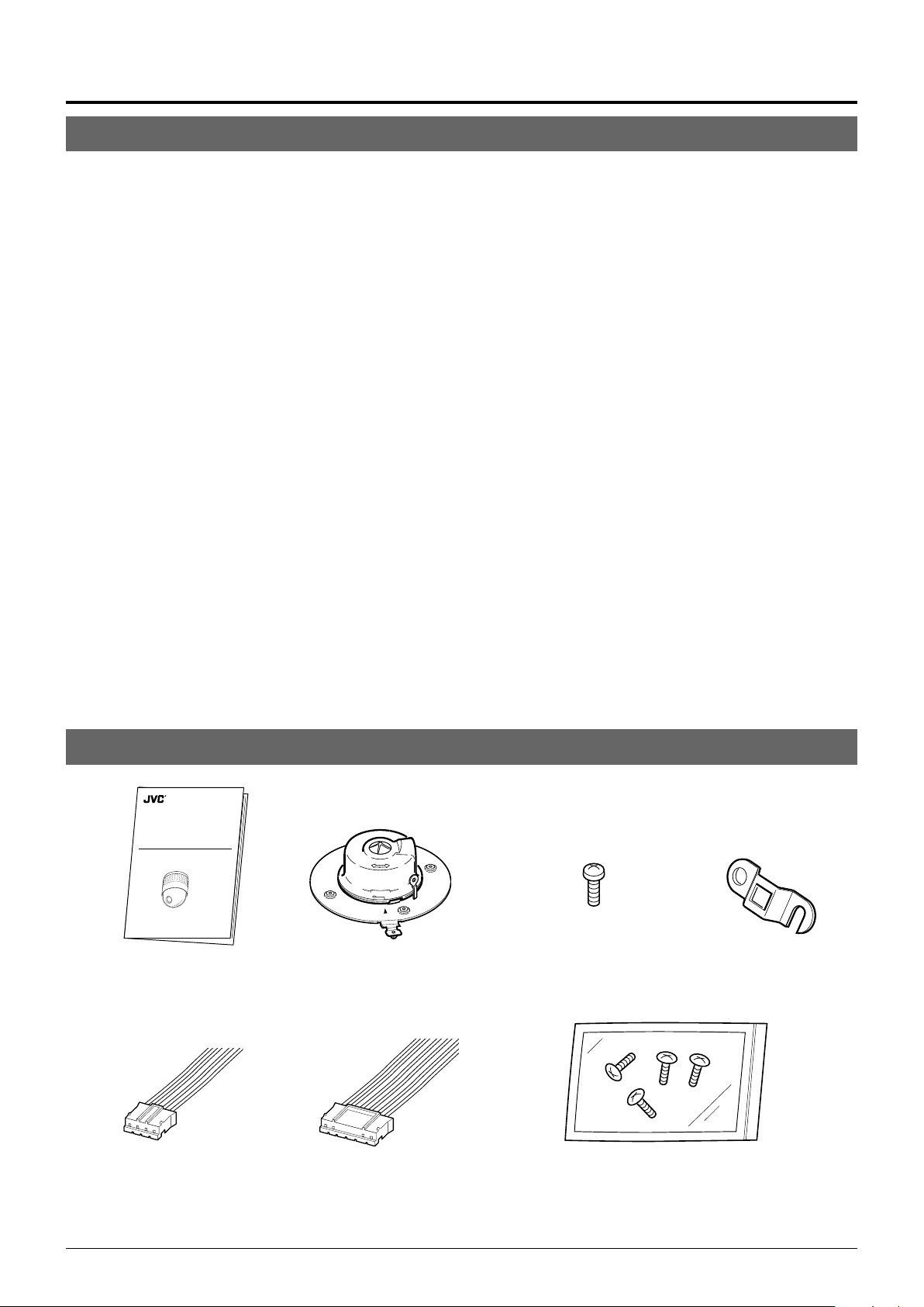
Provided Accessories
DOME TYPE CAMERA
TK-C655
TK-C676
Instructions Ceiling mount
4P Alarm cable
INSTRUCTIONS
TK-C655 Ver.(C)
TK-C676 Ver.(B)
LWT0003-001A-H
6P Alarm cable
Screw
(M3 × 12 mm)
For cable plate
Screws (M 4 x 12 mm)
For the ceiling flush mount bracket
Cable plate
4
Page 5

Safety Precautions
WARNING:
TO REDUCE THE RISK OF FIRE OR
ELECTRIC SHOCK, DO NOT EXPOSE THIS
APPLIANCE TO RAIN OR MOISTURE.
AVERTISSEMENT:
POUR EVITER LES RISQUES D'INCENDIE OU
D'ELECTROCUTION, NE PAS EXPOSER
L'APPAREIL A L'HUMIDITE OU A LA PLUIE.
WARNING
• Install the unit on a strong and stable surface.
This unit has been designed to revolve at high speed. Due to
its weight (about 2.4 kg) and the vibrations it may be subjected to, the camera must be mounted to a sturdy and stable
material. If the ceiling material lacks strength, for example it
is made of a decorative laminated material or plasterboard,
then the mount should be reinforced using materials such as
veneered plywood. If such reinforcement is inadequate images may fluctuate due to vibration or, in the worst case, the
camera may fall and cause a serious accident should there
be anyone below it.
or installation, use the provided ceiling mount and the op-
•F
tional flush mounted ceiling bracket, which is sold separately.
When installing this device the provided ceiling mount and
the optional flush mounted ceiling bracket, which is sold separately should be used. Also be sure to connect the drop
prevention wire and tighten all screws and nuts firmly.
•Power the unit with the rated power voltage.
The power rating for this unit is 24 V AC, 50 Hz/60 Hz. If a
power above this rating is supplied, a malfunction will occur
or, in the worst case, smoke or fire may be produced.
• This unit offers a certain degree of protection against any
damage either to itself or to its connection cable that might
result from indirect lightning strikes, but it is not capable of
preventing all damage by lightning strikes. For example it is
not protected against a direct lightning strike. If lightning damage can be expected in the place where the unit is installed,
be sure to take countermeasures by adding an arrester to
the connection cable, etc.
CAUTION
• Installation of this unit requires special skills. Please be sure
to consult your dealer about installation procedures.
If the mounting screws or nuts are not tightened sufficiently,
the camera may fall from its installation location. Be sure to
tighten the mounting nuts firmly to prevent this happening.
• Inspect the unit periodically.
Check periodically for any deterioration of the mount sec-
tions or loosening of screws due to vibration and ensure that
there is no likelihood of the unit dropping.
5
Page 6

Introduction
Precautions for Correct Operation
● To save energy, turn the system off whenever it is not in
use.
● This camera has been designed for indoor use. It cannot
be used outdoors.
● This camera has been designed to be hung from a ceiling,
do not install it in an upright position on a surface or at an
angle, as this may cause a malfunction or a noticeable shortening of its service life.
● Do not install or use the camera in the following locations.
• In a place exposed to rain or water. (The waterproof characteristics of the camera for TK-C676 are equivalent to
IEC 529.)
• In a place containing vapor or oil soot, for example in a
kitchen.
• In a place outside the operating temperature range (-10°C
to 50°C).
• Near a source of strong radio waves or magnetism, radiation or X-rays.
• In a place where corrosive gassed are generated.
• In a place subject to vibrations.
• In a place with excessive dust.
● Insufficient ventilation of the camera may cause a malfunc-
tion. Be careful not to block ventilation to the camera.
This unit radiates heat from the panel surfaces (top panel
and side panels). Do not install it in a place where a heat
pool may form, such as near a wall.
● Do not install the camera in a place exposed to cold air, for
example near to the air outlet of an air conditioner. Otherwise, moisture may become condensed inside the dome
cover.
● Do not point the lens at a strong light source, for example
the sun, doing so may cause the camera to malfunction.
● The camera incorporates an AGC circuit. As a result, when
it is used under low light conditions the camera gain may
increase automatically. This makes the picture appear uneven , however this is not a malfunction
● When equipment that generates strong magnetism such
as a transceiver is used near to the unit while the AGC
circuit is ON, beat noise, etc may interfere with the picture.
If a transceiver or similar equipment is used keep it a distance of at least 3 meters from this unit.
● In auto iris mode, when the AGC circuit is ON, varying the
iris with the iris control button may not change the picture
brightness. This is due to the automatic gain boost by the
AGC circuit. In this case, set AGC to OFF or use the manual
iris mode.
● In auto iris mode, the iris control button may not function
under certain brightness conditions (i.e. when a sufficient
amount of light cannot be obtained). In this case, set the
iris mode to manual.
● When the camera is used in ATW (Auto White balance)
mode, the colors captured by the camera may differ from
the actual colors being shot due to the mechanics of the
auto-tracking operation within the white balance circuit.
However, this is not a malfunction.
● If a very bright object (such as a lamp) is being monitored,
the picture may contain vertical lines (smear) above and
below the bright object in the picture. This is a phenomenon normal to a solid-state image pickup devices (CCD)
and is not a malfunction.
● The electronic shutter speed of the camera has been set
to 1/50 second at the factory. If the camera is used under a
fluorescent light source in an area with a local power frequency of 60 Hz, change the shutter speed to 1/120 second using the remote control unit. (Note that the sensitivity
will deteriorate slightly.)
However, when the ExDR function is ON, the flicker may
not disappear.
● When the camera is used to monitor the same position over
many hours ( e.g. continuously for 24 hours a day) the contact resistance of the panning mechanism may increase.
This may cause the picture to be affected by noise interference or the remote control operation becoming unstable.
To prevent this happening, once a week, turn the system
off and on in order to initialize the camera and to clean the
contacts.
● Do not touch the lens on the dome cover directly by hand.
Contamination of the cover will lead to deterioration of the
picture quality.
● Since the dome cover is of a hemispherical shape, the pic-
ture tends to become distorted at the edges of the hemisphere. When the camera is tilted and pointed in the horizontal-direction, the picture may be out of focus because
the camera will then capture the edges of the hemisphere.
● When an object is located near a light source or contains a
large difference in brightness, a ghost may interfere with
the picture. This phenomenon is due to the characteristics
of the dome cover and the built-in lens and is not a malfunction.
● Observe the following points when carrying out mainte-
nance of the camera.
•Turn the system off before proceeding.
• Clean the dome cover using a lens cleaning cloth (or tissue).
The dome cover may become stained in a very short
period in certain operating environments. If the dome
cover lens becomes excessively contaminated, clean it
with a lens cleaning cloth (or tissue) moistened with a
solution of neutral detergent in water.
6
Page 7

䡲 Note on consumable parts
The following parts are consumable and should be replaced
after a certain number of hours or a count of operations.
The service lives given below are only typical values. They
may vary depending on the operating environment and conditions.
Note that the replacement of consumable parts is chargeable even when they are replaced before the termination
of the warranty period.
• Zoom lens assembly
Zooming operation : 2 million times
Focusing operation : 4 million times
• Slip rings : 5 million operations
• Cooling fan : Approx. 30,000 hours
• Alarm output 1 relay : 200,000 times of operation
䡲 Note on auto focusing
Although this unit incorporates a one-push auto-focusing
system and EASY AF functions, auto-focusing may sometimes be impossible depending on the object and camera
setup. In this case, adjust the focusing manually.
Objects and images with which auto focusing may be
difficult:
• When the image brightness is extremely high.
• When the image brightness is extremely low.
• When the image brightness varies continuously (for example when the object is a flashing light).
• When the image contrast (difference between bright and
dark) is very poor.
•When the image does not contain a vertical contour component.
• When vertical stripe patterns recur on the screen.
Camera setups with which auto focusing may be difficult:
• When the AGC is activated and the image is coarse.
• When SENSE UP is activated and the image contains
only little motion.
• When electronic zooming is activated and the image does
not contain a large enough contour component.
䡲 Zooming
When zooming is stopped near the TELE end during manual
operation or by selecting a preset position, focusing may
deviate slightly. In addition, the manual zooming operation
may not always be smooth.
These phenomena are due to the characteristics of the builtin lens and are not malfunctions.
䡲 Preset positions
• The zooming position of the camera can be set to a total
of 100 preset positions, including the home position.
• The electronic zoom can be preset up to x2.
However, if the electronic zoom menu on the screen is
set to OFF even presetting the electronic zooming to x2 ,
the camera itself moves to the preset position without the
electronic zooming being activated.
• It is not permitted to preset the electronic zoom to a larger
ratio than x2. The message "INVALID POSITION
(D.ZOOM)" will appear on the screen if a larger ratio than
x2 is set.
• The TILT position can be set and operated only between
0° to 90° even when the item “FLIP” is set to DIGITAL.
(A TILT position between 91° and 180° cannot be set or
operated. The message "INVALID POSITION (TILT) will
appear on the screen if a larger TILT position than 90° is
set. )
䡲 Attention for installation
• Do not install at the location where the temperature
changes rapidly such as near the air-con duct or the door
which external air might flow in.
The dome cover may fog or condense.
• If installing this unit when the humidity is high, the dome
cover may fog due to there is moisture inside.
7
Page 8
Connections & Installation
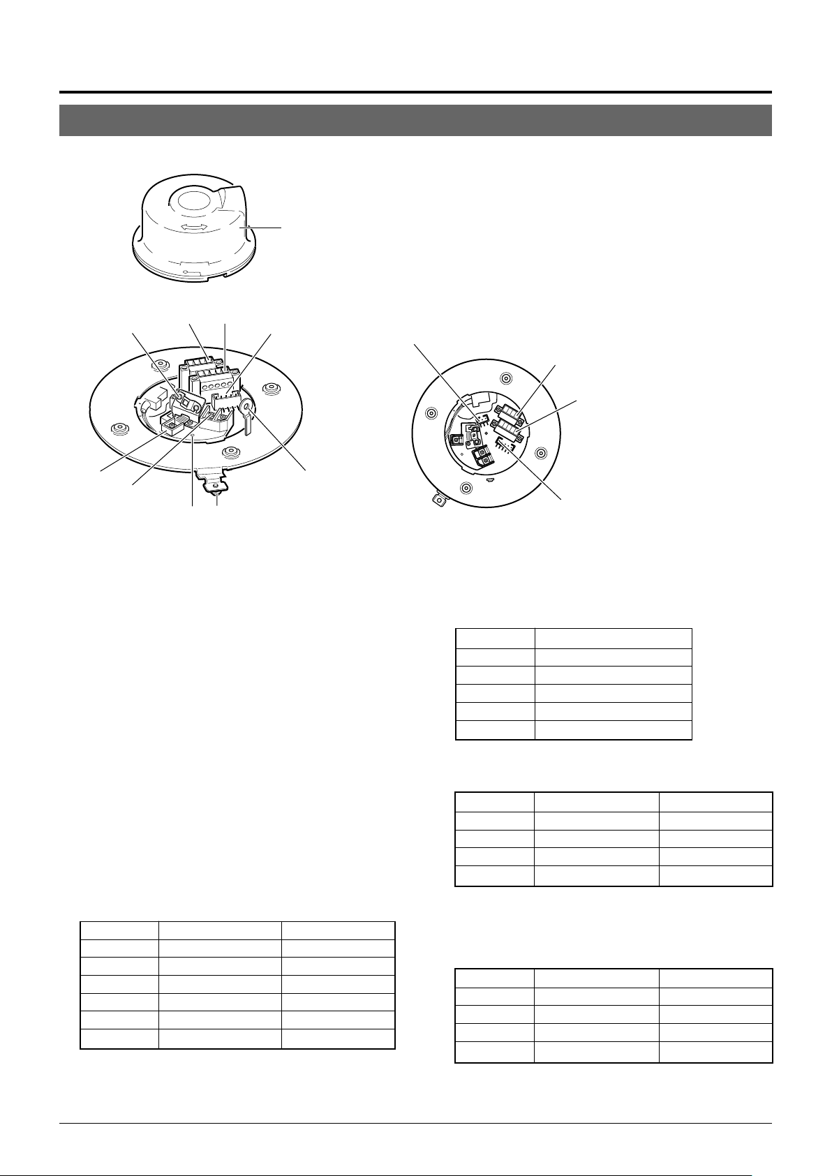
Controls, Connectors and Indicators
䡵 Ceiling Mount
0
Cover
96
1
87
5
2
43
(Connector side)
[VIDEO OUT] Coaxial Cable Connectors
1
Output connector of a composite video signal (1 V(p-p))
with an output impedance of 75 Ω, to be connected to a
switcher, etc.
[AC ` 24V INPUT] Connector
2
Connect to a 24 V AC power supply.
Cover Position Alignment Mark
3
When attaching the cover, use this mark to align its final
position correctly.
Locking Screw
4
Tighten this screw to fasten the camera clamping bracket
.
*
Safety Wire Hole
5
To prepare for possible dropping of the camera, pass the
wire from the ceiling slab or channel through this hole.
Alarm Input Terminals (CN26)
6
Input terminals for Alarm 2, Alarm 3 and Alarm 4.
Connect the provided cables to these terminals.
P. 1 7
☞
Pin No. Signal Name Color of Cable
1 Alarm input 2 Brown
2 GND Red
3 Alarm input 3 Orange
4 GND Yellow
5 Alarm input 4 Violet
6 GND Gray
Pin 1 of alarm output terminal
9
(CN24)
(Terminal Pin Layout)
[ALARM I/O] Input/Output Terminals (CN23)
7
Te r minals for Alarm input 1 and Alarm output 1.
P. 1 7
☞
Pin No. Signal Name
1 Alarm output 1
2 Alarm output 1 (COM)
3 Alarm output 1
4 Alarm input 1
5 GND
[CONTROL] Terminals (CN22)
8
Connect to a RM-P2580 remote control unit.
Pin No. Signal Name Mark
1 TX + A
2 TX – B
3 RX + C
4 RX – D
Alarm Output Terminals (CN24)
9
Output terminals for Alarm 2 and Alarm 3.
Connect the provided cables to these terminals.
P. 1 7
☞
Pin No. Signal Name Color of Cable
1 Alarm output 2 + Red
2 Alarm output 2 – White
3 Alarm output 3 + Orange
4 Alarm output 3 – Gray
Pin 1 of CONTROL terminal
8
(CN22)
Pin 1 of ALARM I/O terminal
7
(CN23)
Pin 1 of alarm input terminal
6
(CN26)
(N.OPEN)
(N.CLOSE)
䡬
䡬
䡬
䡬
8
Page 9
#
%
&
^
$
*
⁄
!
#
@
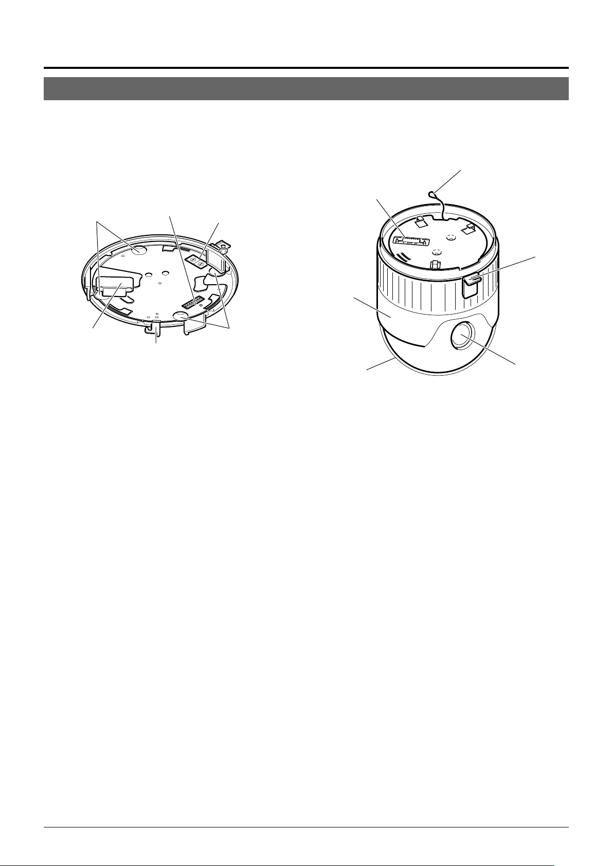
(Setting switch side)
Cover
0
For protection against water drips. Slit the rubber cap on
this cover and pass the cable through the slits.
P. 1 6
☞
Camera Connector (Female)
!
Connect to ^, the Male Connector on the camera.
Drop Prevention Hook
@
Attach the Drop Prevention Wire & to this hook to prevent
the camera from falling.
Clamping Holes (x 4)
#
Attach the camera to a ceiling or to a Ceiling Flush Mount
Bracket (optionally available) using these holes.
[MACHINE ID] Switch
$
When an RS-485 communication system is used, for example when using the camera in a system controlled by
an RM-P2580, set the camera IDs individually for each
camera.
P. 1 5
☞
)
Connector (Male)
^
Connect to !, the Female Camera Connector on the Ceil-
ing Mount.
Drop Prevention Wire
&
Attach this wire to the Drop Prevention Hook @ on the
Ceiling Mount.
Camera Clamping Bracket
*
In order to clamp the camera onto the Ceiling Mount, insert and tighten the Locking Screw
Lens
(
The lens cannot be replaced.
Dome Cover
)
The dome cover is fragile. Take care when handling it.
Camera Body Cover
⁄
Do not remove the camera body cover while the camera is
installed on a ceiling. Doing so will cause the dome cover
to fall down.
(
into this bracket.
4
Setting Switches
%
Use these to set the PROTOCOL, etc.
P. 1 4
☞
9
Page 10
TO CAMERA
DATA I / O
RX
RX
TX
TX
COM
COM
10/2
12/4
13/5
14/6
16/8
COM
COM
COM
CAMERA
SW
UNIT
ALARM
AUTO
MONITOR
OUTPUT
MONITOR
VIDEO INPUT
VIDEO OUTPUT
OUTPUT
ON
POWER
OFF
ON
AC INPUT
Connections & Installation
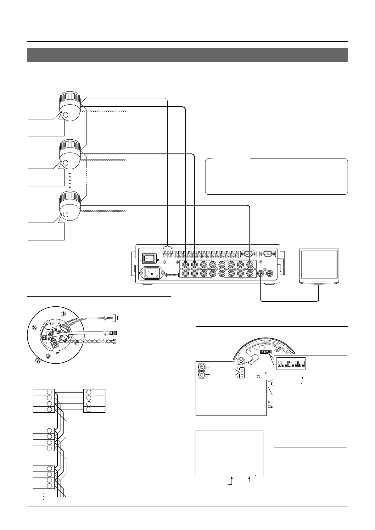
A Multi-Drop Communication System
䡵 A system that employs the RM-P2580 as the controller
The following figure shows a system that can accommodate up to eight cameras. (100 positions can be preset per camera.)
TK-C655/
TK-C676
Camera 1
MACHINE ID: 01
Switch 8: OFF
(RX TERM)
TK-C655/
TK-C676
Camera 2
MACHINE ID: 02
Switch 8: OFF
(RX TERM)
TK-C655/
TK-C676
Camera 8
MACHINE ID: 08
Switch 8: ON
(RX TERM)
Control signal cable
Coaxial cable
Remote control unit
RM-P2580
AC 24 V
power supply
CAUTION
(
AC 24 V
power supply
CAUTION
(
AC 24 V
power supply
CAUTION
(
CAMERA
TO
TO CAMERA
+
RX
RX
ON
-
+
TX
-
TX
431 2 875 6
Observe the following points when connecting components together:
•Turn all the components off before proceeding.
• Read the instruction manuals of all components before proceeding.
•For the types and lengths of connection cables, see “Cable
Connections” on page 16.
• Do not connect the control signal cables in a loop.
COM
1 2 3 4 5 6 7 8
1
1
DATA I / O
COM
9/1 10/2
2 3 4 5 6 7
2 3 4 5 6 7
CAUTIONS
● The AC 24 V power supply must be isolated from the pri-
mary line. (ISOLATED POWER ONLY)
● In order to prevent an excessive current flow through the
power supply wire or camera due to a short circuit, a fuse
must be installed in the power supply line.
11/3 12/4
13/5
14/6
15/7 16/8
VIDEO INPUT
VIDEO OUTPUT
UNIT
CAMERA
COM
COM
COM
SW
ALARM
AUTO
SERIAL-2SERIAL-1
8
MONITOR
MONITOR
OUTPUT
OUTPUT
1
2
8
Monitor
Cable connections
☞
P. 1 6
(Terminal side of Ceiling Mount)
Control signal cable
Coaxial cable
Power cable
Connection of the control signal cable
(A twisted pair cable is recommended.)
Camera 1
CONTROL terminals
TX +A
TX –B
RX +C
RX –D
Camera 2
CONTROL
terminals
+
TX
A
TX –B
RX +C
RX –D
Camera 3
CONTROL
terminals
TX +A
TX –B
RX +C
RX –D
RM-P2580
terminal
+
RX
A
–
RX
B
TX +C
TX –D
Each terminal on the camera and the RMP2580 is marked A䡬, B䡬, C䡬 or D䡬. In order
to facilitate understanding and to avoid
connection mistakes, it is recommended
to connect the terminals carrying the
same marks.
10
To the TO CAMERA connector of the
RM-P2580 and to the next camera
To the CAMERA INPUT connector
of the RM-P2580
To AC 24V power supply
CAUTION
(
MONITOR
OUTPUT 1
Switch settings
☞
P. 1 4
(Setting switches are on the side of the Ceiling Mount)
Machine ID
3
2
4
1
5
0
6
9
Figure of 1
7
8
3
2
4
1
5
0
6
Figure of 10
9
7
8
Set it to the same number as the
VIDEO INPUT terminal of the RMP2580.
(Example) Camera 1:
Set the figure of 10 to “0” and
figure of 1 to “1”.
Camera 1 monitor display
at power ON
LPROCESS<<>> I INTIA
:--I--PAN
:--I--TILT
Duplex display ID No. display
(ID check procedure
DUPLEX ID- 01ROT>P COOL
☞
P. 15)
1234678
5
F
F
O
Switch 1
Switch 2
Switch 4 : ON
Switch 5 : OFF
Switch 7 : Invalid (Set to OFF)
Switch 8 :
:
Invalid (Set to OFF.)
:
Set to ON only for the
camera connected at
the end of the control
signal cable.
Set to OFF for all
other cameras.
Page 11
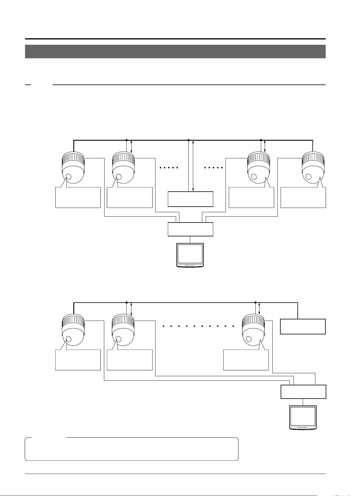
䡵 A system that does not employ the RM-P2580 as the controller
MEMO
Be sure to terminate the control signal cable at both ends. The cables (length of stub) connecting pieces of non-terminated
equipment (cameras or controllers) must be as short as possible. If the length of stub is too long, control precision may suffer.
● When the controller is not located at the end of a system.
(An AC 24V power source must be supplied to each camera)
CAUTION
(
CONTROL Cable
CAM1 CAM2
PROTOCOL(1) : ON
MACHINE ID : 01
RX TERM : ON
PROTOCOL(1) : ON
MACHINE ID : 02
RX TERM : OFF
• Set the TERM switches of the cameras at each end
(CAM1 and CAM32) to ON, and the TERM switches of
Length of stub
CONTROLLER*
VIDEO
SWITCHER, etc.
the other cameras to OFF.
• Do not terminate at the controller.
● When the controller is located at the end of a system.
(An AC 24V power source must be supplied to each camera)
CAUTION
(
CONTROL Cable
CAM1 CAM2
Length of stub
Length of stub
CAM31 CAM32
PROTOCOL(1) : ON
MACHINE ID : 31
RX TERM : OFF
CAM32
Length of stub
PROTOCOL(1) : ON
MACHINE ID : 32
RX TERM : ON
Length of stub
Terminate it
with 110 Ω.
PROTOCOL(1) : ON
MACHINE ID : 01
RX TERM : ON
PROTOCOL(1) : ON
MACHINE ID : 02
RX TERM : OFF
• Set the TERM switch of CAM1 to ON, and terminate at the controller with a resistance of 110 Ω.
Set the TERM switches of the other cameras to OFF.
CAUTIONS
● The AC 24 V power supply must be isolated from the primary line. (ISOLATED POWER ONLY)
● In order to prevent an excessive current flow through the power supply wire or camera due to a
short circuit, a fuse must be installed in the power supply line.
CONTROLLER*
PROTOCOL(1) : ON
MACHINE ID : 32
RX TERM : OFF
VIDEO
SWITCHER, etc.
11
Page 12
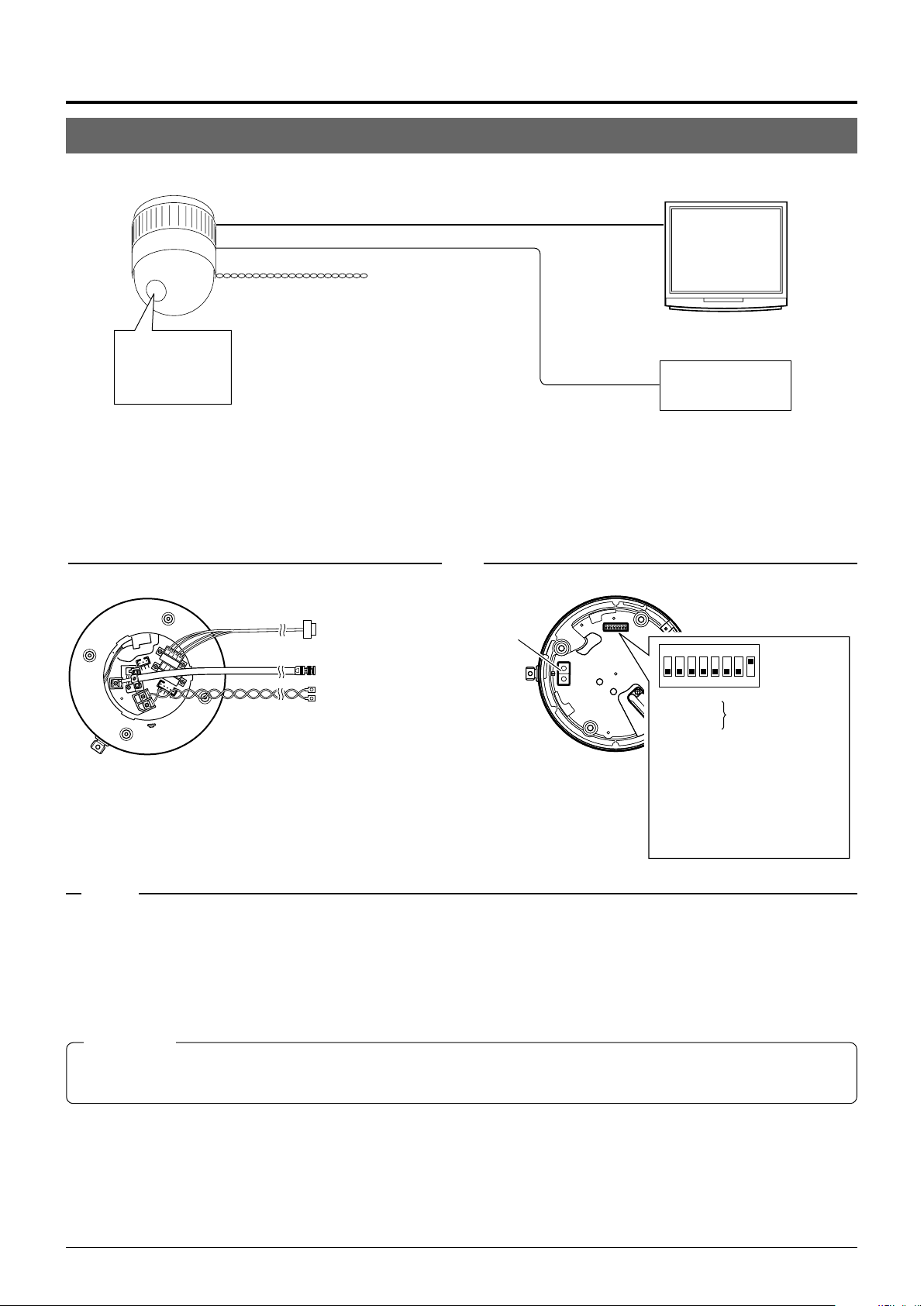
Connections & Installation
Setting not
required
123
4
678
5
O
F
F
Setting not
required
Switch 1 :
Switch 2 :
Switch 4 : OFF
Switch 5 :
Configure in accordance
with the requirements of the controller
communication system.
Switch 7 : Invalid (Set to OFF)
Switch 8 : ON
Invalid (Set to OFF)
Point-to-Point Communication System
The following illustration shows a system in which a remote control unit (or a similar piece of equipment) controls a single camera.
Video out
Control signal cable
AC 24 V
power supply
CAUTION
(
Switch 4 : OFF
(Point to Point)
Switch 8 : ON
(Terminated 110Ω)
Observe the following points when connecting components together:
•Turn all the components off before proceeding.
• Read the instruction manuals of all components before proceeding.
Monitor
Controller
Cable connections
(Terminal side of the Ceiling Mount)
P. 1 6
☞
Control signal cable
To controller
Coaxial cable
Power cable
To monitor
To the AC 24V power supply
(
CAUTION
Switch settings
(Setting switches are on the side of the Ceiling Mount)
☞
P. 1 4
MEMO
If this camera or the cables connected to this camera are used in places subject to strong electromagnetic waves or other forms
of magnetism, for example near a radio or TV transmitter, a power transformer or an electric motor, the picture may suffer from
noise and colors may be affected.
An optionally available controller is required to use a TK-C655 or TK-C676 camera. Please contact your local dealer or installer
for more information about these controllers.
CAUTIONS
● The AC 24 V power supply must be isolated from the primary line. (ISOLATED POWER ONLY)
● In order to prevent an excessive current flow through the power supply wire or camera due to a short circuit, a fuse must be installed in the
power supply line.
12
Page 13
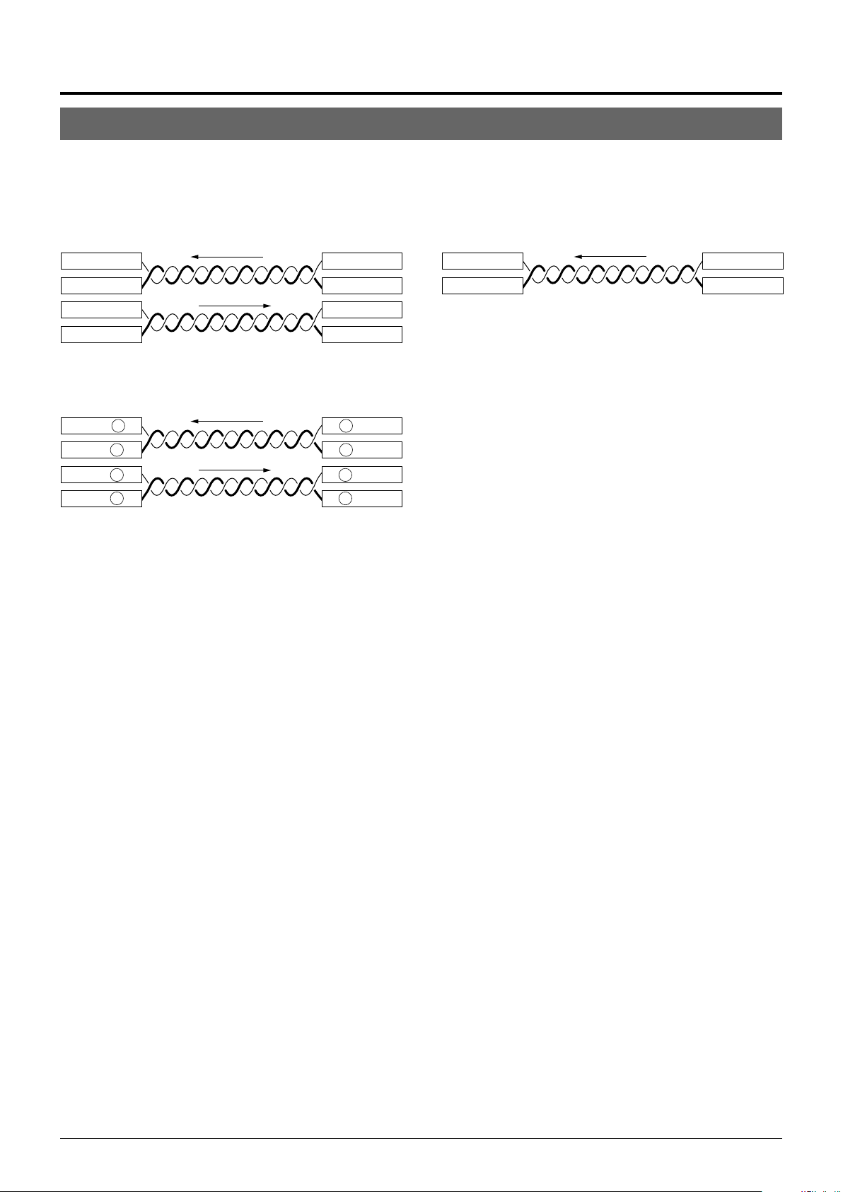
Use twisted-pair cables for the connections.
Camera Controller
RX+
RX–
TX+
TX–
●Duplex
When the camera is controlled using the full duplex protocol, set Switch 5 to OFF.
Camera Controller
RX+
RX–
TX+
TX–
Four wires must be connected.
For example (connection with an RM-P2580)
Camera RM-P2580
RX+ C
RX– D
TX+ A
TX– B
TX+
TX–
RX+
RX–
C TX+
D TX–
A RX+
B RX–
●Simplex
When the camera is controlled using the simplex transmission protocol, set Switch 5 to ON.
Tw o wires must be connected.
13
Page 14
Connections & Installation
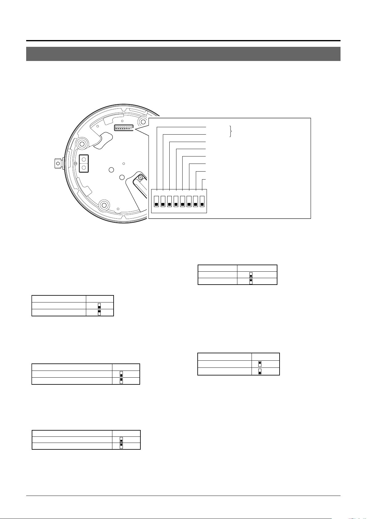
Switch Settings
Set the switches on the Ceiling Mount before installing the camera.
Settings vary according to configuration of the system used.
䡵 Setting switches
123
O
● Switches 1, 2
These switches must be set to OFF.
● DISP (Switch 3)
This switch selects whether “MANUAL” is displayed in the
screen when a remote control unit is used to move the camera manually (to a position other than those preset.).
Switch 3MANUAL
Displayed
Not displayed
(Initial setting: Displayed)
● PROTOCOL (1) (Switch 4)
Selects whether a single camera or multiple cameras are controlled in a system.
Set PROTOCOL(1) to Multi drop when connecting multiple
cameras in series.
Switch 4PROTOCOL (1)
Point to point OFF
Multi drop (when using the RM-P2580)
(Initial set: OFF)
ON
When set to Multi drop, be sure to set the Machine ID of each camera.
● PROTOCOL (2) (Switch 5)
Set this switch according to the communication protocol used
when controlling the cameras.
PROTOCOL (2)
Duplex (when using the RM-P2580)
Simplex ON
(Initial set: OFF)
Switch 5
OFF
Switch 1
Switch 2
Invalid (Set to OFF)
Switch 3 DISP
Switch 4 PROTOCOL(1)
Switch 5 PROTOCOL(2)
Switch 6 SYNC
Switch 7 Invalid (Set to OFF)
Switch 8 RX TERM
4
678
5
F
F
● SYNC (Switch 6)
When this switch is set to ON, the vertical sync of the camera
becomes locked to the frequency of the AC power line.
SYNC Switch 6
INT OFF
LL ON
(Initial set: OFF)
(LL mode : 50 Hz area only)
● Switch 7
This switch must be set to OFF.
● RX TERM (Switch 8)
This switch sets whether or not the section between control
signal terminals RX + and RX – is to be terminated (with a
resistance of 110 Ω.)
Switch 8RX Termination
Te r minated (110 Ω)ON
Open OFF
(Initial setting: Terminated (110 Ω))
When the system in which this camera is used is a multidrop system (RS-485 system), set only the camera located
at the extreme end of the control signal cables to “Terminated” and set the other cameras to “Open”.
14
Page 15
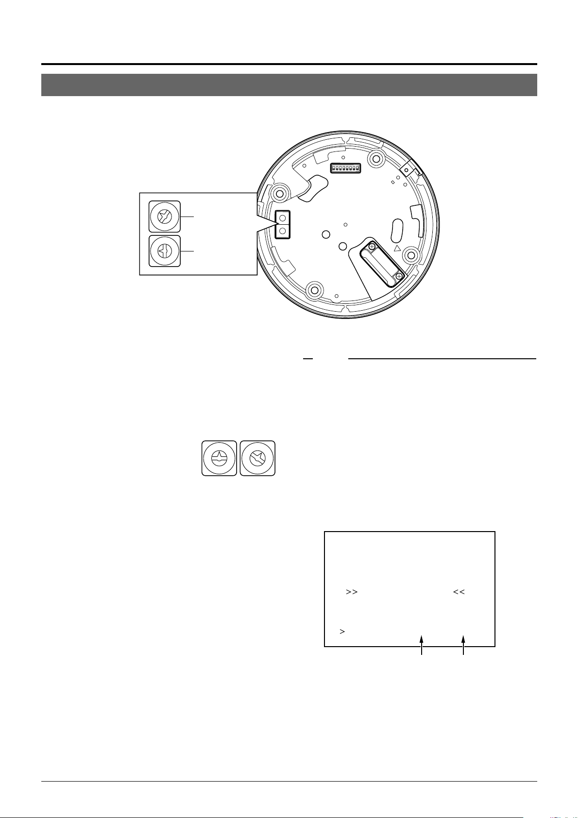
䡵 Setting switches
3
2
4
1
5
0
6
7
4
5
6
7
Figure of 1
Figure of 10
9
8
3
2
1
0
9
8
● Machine ID
When using a multi-drop system with a remote control unit
such as a RM-P2580, the machine IDs need to be set for
each camera.
Machine IDs are used to identify each of the multiple cameras connected to the RM-P2580. Set the machine IDs according to the corresponding VIDEO INPUT terminal numbers on the RM-P2580.
(Example)
The machine ID of the camera connected to VIDEO INPUT 1 should be
set to “0” “1” as shown on the right.
“0” “1”
0
1
9
8
7
6
Figure of 10 Figure of 1
9
2
8
3
7
4
5
MEMO
In a system using an RM-P2580, multiple cameras are connected
by a single set of control cables. An error in the switch setting of
even a single camera will make the entire system inoperable.
<Camera ID check procedure>
1.
0
1
2
3
4
6
5
Set the picture being monitored to that of the camera to
be checked.
2.
Tu rn the AC 24V power source of the camera OFF and
then ON again.
3.
The camera now performs the initialization operation and
the following display appears:
PROCESSIN TIIAL
I--PNA:-I--TI TL:--
UP LEX I D - 10PROT OOC L D
“DUPLEX” should be displayed. “ID-□□” is displayed.
4.
Ensure that “DUPLEX” and “ID-□□” are displayed and
Ensure that the number
□□
is correct.
that the ID number is identical to the VIDEO INPUT terminal number on the RM-P2580.
5.
If the ID number is incorrect, reset it accordingly.
15
Page 16

Power cable
Control signal cable
To a remote controller
such as RM-P2580
To the monitor, etc.
To the AC 24 V
power supply
To a device with
alarm input
Coaxial cable
Alarm signal cable
Maximum cable length
100 m 260 m 410 m 500 m
Wire diameter (mm) 1.0 or more 1.6 or more 2.0 or more 2.6 or more
Connections & Installation
Cable Connections
Connect cables to the Ceiling Mount as described below.
1.
Make a 90 mm diameter hole in the ceiling.
Diameter 90 mm
2.
Remove the cover from the Ceiling Mount.
RELEASE LOCK
Cover
Ceiling mount
4.
Connect the cables.
Connect the cables to the terminals on the Ceiling Mount.
The four connection cables should consist of a AC 24V
power cable, a coaxial cable, a control signal cable and
an alarm signal cable.
AC 24V power cable
This cable connects the AC 24V power supply to the AC
24V input connector. To prevent connection errors and
disconnections, the use of lug plate for connections to the
AC 24 V INPUT connector is recommended.
3.
Pass the cables through the cover.
Make slits in the rubber cap on the cover as shown in the
diagram below. Pull the cables through the hole in the
ceiling and pass the cables through the slits.
Cap (Top)
Cap (Side)
Connector
Maximum diameter 31 mm
Tube
Maximum diameter
22 mm
33 mm or less
Drip-proof pipe
The diameter of the cover hole without the cap is 20.5 mm.
When the camera is installed in a place where it may sometimes be exposed to water splashes, for example under
eaves, enclose cables in a drip-proof pipe.
TK-C655: Be sure to use a drip-proof pipe. The
maximum diametre of the pipe connector is 31 mm.
TK-C676: Be sure to use a water-drip pipe that com-
plies with the IP52. standard. The maximum diameter of the pipe connector is
31 mm.
When distributing the cable from the side, use the WBS573 ceiling direct-mount bracket. In this case, the length
of the connector should be 33 mm or less, and the maximum diameter of the tube should be 22 mm or less.
16
When a 2-conductor VVF (Vinyl-insulated vinyl-sheath cable) is used, the maximum connection length is as shown
below. (These are merely the standard reference values.)
CAUTIONS
● When a thin cables are used the cable resistance increases.
As a result, when the power consumption of the unit is at its
maximum level (during the simultaneous operation of panning
and tilting) the effective voltage will drop.
If the voltage does drop while the camera is in use, performance can become unstable and preset positions may not be
reproduced accurately.
To prevent problems, use thicker cables that have a lower resistance or decrease the cable length by installing the power
supply unit close to the camera. Attempt to reduce drops in
voltage to less than 10% while the rated current level of the
camera is flowing through the cable.
● Do not connect an AC 24V cable directly to an AC 230 V outlet.
This will damage the unit.
● The AC 24 V power supply must be isolated from the primary
line. (ISOLATED POWER ONLY)
● In order to prevent an excessive current flow through the pow-
er supply wire or camera due to a short circuit, a fuse must be
installed in the power supply line.
Page 17

Coaxial cable
Connecting a RG-59 coaxial cable.
If a RG-11 coaxial cable is used it cannot be connected directly to the terminal board. To use such a
cable, connect a RG-59 cable to the camera and then
connect the RG-11 cable to the RG-59 cable.
Treat the extremity of the coaxial cable as shown below
before connecting it.
Fold back the mesh wires and secure them with insulation tape in order
to prevent them from becoming loose and thus causing a short circuit.
Mesh wiresPolyethylene
Conductor
wire
If the cable is extended, the signal attenuation is increased,
the resolution drops and the noise increases. Should it be
required to extend the cable, use a thicker cable or a cable length compensator.
To lead the coaxial cable through the cap on the side of
the cover, change the positioning of the cable plate as
shown below.
7
(5)
Insulation tape
The figures inside the brackets ( ) are the dimensions
when the coaxial cable is distributed from the side of the cover.
(Unit : mm)
17
(12)
Alarm signal cables
P. 8
☞
Alarm output terminals (CN24)
Connect the provided 4P Alarm cable
to these terminals.
Alarm input/output terminals
(CN23)
Alarm input terminals (CN26)
Connect the provided 6P Alarm cable
to these terminals.
Electrical Specification of the Alarm Output Terminals
N. OPEN
COM.
N. CLOSE
• The ALARM 1 terminal outputs a
contact signal. In the alarm status,
the section between N.OPEN and
COM is shorted (makes an electrical contact) and the section between N.CLOSE and COM is
opened (breaks contact).
Rating
Maximum applied voltage: 30 V
DC or 24 V AC
Maximum applied current: 2 A
Contact life: 200,000 times of
operation
Provided screw
Screw removed in the
Provided cable
plate
figure on the left
Control signal cables
RM-P2580 units allow the connection of up to eight cameras to a single set of control signal cables. The overall
maximum permissible length of these control signal cables
is 1200 meters.
Cable
Flat-blade
screwdriver
Cables with a thickness between 16 AWG and 26 AWG can be used.
Connect the control signal cables so that the TX+ and TX- signals
form a pair and the RX+ and RX- signals form another pair.
4 mm
The connector can be released by
loosening the screws on the two sides as
shown in the figure.
Flat-blade screwdriver
Strip the coating of each cable by about 4
mm before inserting it. After connecting all
of the cables, turn the screws on the side
to fasten the connectors.
It is recommended to use a 4-core (a pair)
twisted pair cable (0.65) or a twisted pair
cable of category 3 or higher which is
used for a Ethernet.
ALARM2+
or
ALARM3+
22 Ω
• The ALARM 2 and ALARM 3 terminals output open-collector signals insulated by photocouplers.
The terminal is ON in the alarm status.
As these terminals are provided
with polarity, make sure that the
voltage at the + terminal is higher
than that at the – terminal.
ALARM2–
or
ALARM3–
Do not apply inverse voltage to prevent damage of these terminals.
Rating
Maximum applied voltage: 20 V DC
Maximum drive current: 25 mA
Electrical Specifications of Alarm Input Terminals
ALARM1
GND
• Use the appropriate menu to select whether the alarm is
identified by shorting (making contact) or by opening (breaking contact).
• Apply an alarm signal for at least 200 ms. If it is shorter, it is not
guaranteed that the signal will be recognized as an alarm signal.
5.
Attach the cover.
Attach the cover to the ceiling mount by reversing the
operations in step
•To prevent penetration of noise in the
internal circuitry, apply a non-voltage
contact signal to the ALARM input
terminal. Never apply a voltage.
2
.
CAUTION
In order to prevent foreign objects from entering inside the ceiling
mount be sure to attach the hemispherical cover correctly. The
penetration of foreign objects into the ceiling mount may cause a
malfunction and smoking or in the worst case a fire ignition.
17
Page 18

Connections & Installation
Attaching the Ceiling Mount
To a ceiling slab or channel
Safety wire hole
Ceiling mount
Rubber packings
(Four on each side)
1.
Attaching a safety wire.
Attach a safety wire to the ceiling mount and to the ceiling slab or channel to prevent the unit from dropping.
First attach the safety wire to the ceiling mount by passing the wire through the safety wire hole (see the diagram on the left).
MEMO
● Connect the wire so that it can be insulated from the ceiling struc-
ture. If the ceiling structure is made of a metallic material, improper insulation with the camera may produce noise in the video.
● Use a wire and ceiling attachment having sufficient length and
strength to prevent danger in case the camera drops.
● A safety wire is not provided. Please select an appropriate com-
mercially available wire.
2.
Attaching the ceiling mount to the ceiling.
While taking care not to catch the connection cables, attach the ceiling mount to the ceiling using four screws
(as shown in the diagram). Use M4-sized screws or bolts.
If woodscrews are used, use those with a diameter of 4.1
mm.
Screws
Attaching the Camera
Attach Drop
Prevention Wire
to this hook.
Drop Prevention
Wire
MEMO
● Be sure to use four screws and attach them firmly. If the screws
are not tightened firmly, dust and moisture may penetrate through
the screw holes.
● The rubber packings attached to the ceiling mount screw holes of
the ceiling mount play the role of insulation in case the ceiling
structure is made of a metallic material as well as the role of drip
proofing. If the ceiling structure is made of a metallic material,
improper insulation with the camera may produce noise in the
video. To prevent this occurring, be sure to ensure correct insulation of the installation.
1.
Attach the drop prevention wire.
As shown in the diagram, take the drop prevention wire
from the camera and attach it to the hook on the ceiling
mount.
Be sure to connect the drop prevention wire. Otherwise,
the camera will not fit properly to the ceiling mount. If
they are engaged forcibly, they may be damaged.
CAUTION
Be sure to attach the drop prevention wire. Otherwise, the camera is in danger of falling.
18
Page 19

Ceiling Mount
Camera
Camera clamping bracket
Lock screw
Camera clamping
bracket
2.
Ensure that the lock screw is loose.
The camera cannot be attached properly if the lock screw
of the Ceiling Mount is too tight.
3.
Fit the camera.
Check the position of the camera clamping bracket and
that of the lock screw, and fit the camera onto the ceiling
mount.
Lock screw
Rotate the camera
clockwise.
4.
Rotate the camera.
Make sure that the camera is horizontal, then turn the
camera clockwise until it stops. Ensure that the cameraclamping bracket is in line with the lock screw of the Ceiling Mount.
5.
Tighten the lock screw.
Tighten the lock screw using a Phillips screwdriver.
CAUTION
If the lock screw is not tightened firmly, the camera may rattle or
fall down. Be sure to tighten the lock screw firmly.
*To remove of the camera from the ceiling
1
mount, reverse the steps
to 5.
Tighten the lock screw.
19
Page 20

Setting Up the Camera Using an RM-P2580
Setup Procedure
In systems using an RM-P2580 remote control unit, the menus for use during camera setup can be displayed on the remote control
unit. (Please refer to the instructions for RM-P2580.)
<Setting the camera menus from an RM-P2580>
MENU button
SET button
Power switch
(Rear panel)
POWER lamp
REMOTE CONTROL UNIT
SETUP
MENU SET
CLOSE
NEAR
WIDE
SPEED
IRIS
FOCUS
AF
ZOOM
POWER
ALARM
KEY LOCK
OPEN
FAR
TELE CLEAR
CAMERA POSITION
CAMERA/POSITION
1
2
3
4
5
6
7
8
9
0
ENTER
/HOME
CAMERA
OPTION1OPTION
AUTO
PAN
POSITION
AUTO
PATROL
RM-P2580
AUTO F-1 F-2 F-3
PAN/TILTLENS
2
cursor
POS ITION SETUP. .
C AMERA . .
CONT ROL UN I T . .
SETUP
SETUP menu of the remote control unit
PAN/TILT
lever
1.
Set the Power switch on the rear panel of the RMP2580 to ON.
The POWER lamp lights up.
2.
Press and hold the MENU button for 3 seconds.
• The LED of the MENU button lights up.
• The SETUP menu of the remote control unit is displayed on the
monitor connected to MONITOR OUTPUT-1.
3.
Move the PAN/TILT lever downward to move the
cursor (>) to “CAMERA” in the menu.
• Tilting the lever upward (䊱) moves the cursor upward.
• Tilting the lever downward (
4.
Press the SET button.
• The MENU screen for the camera is displayed.
• Items followed by “..” have further submenus.
䊲) moves the cursor downward.
CAM. FUNC T I ON1 . .
CAM. FUNC T I ON2 . .
CAM. T I T L E / AL ARM. .
CAM. V I DEO ADJUST . .
CAM. A LC . .
HOME MOT ION DE T EC T . .
AUTO PAN / PA TROL / TRACE . .
POS I . FUNCT I ON SE T . .
FACTORY SETT INGS. .
–––M E N U–––
SETUP menu of the camera
Change mark
–––CAMERA FUNCT I ON – – –
V . P H A S E 0
POS .TITLE LOC. UP-L
FL I P DIGI TAL
VAR .P/T SPEED ON
EASY AF OFF
D.ZOOM MAX X2
V . S H A R P N E S S N O R M A L
TILT LIMIT 5 °
..KSAMETAVIRP
Example of a submenu
Indication of
presence of
submenus
5.
Tilt the PAN/TILT lever up or down to select an item.
6.
Tilt the PAN/TILT lever to the left or right to change
the value of the item.
• Tilting the lever toward the left (䊴 ) decreases the value.
• Tilting the lever toward the right (
7.
Press the MENU button.
After completing the setup of the menu items, press the MENU button to return to the previous menu screen.
䊳) increases the value.
20
Page 21

Menu Screen Flow
The menu screens are arranged in a hierarchical structure as shown below. Refer to the respective reference pages for the details of each
menu.
Normal screen
POS I T I ON SETU P . .
CAMERA. .
CONT ROL UN I T . .
SETUP screen of the remote control unit
CAM. FUNCT I ON1 . .
CAM. FUNCT I ON2 . .
CAM. T I T LE / ALARM . .
CAM. V I DEO ADJUS T . .
CAM. ALC . .
HOME MOT I ON D E TE CT . .
AUTO PAN / PATROL / TRACE . .
POS I . FUNCT I ON S ET . .
FACTORY SETT I NGS. .
SETUP
––– M E N U – – –
c
MENU screen
• Menus for setting up the function of
each camera:
CAM. FUNCTION1
CAM. FUNCTION2
CAM. TITLE/ALARM
CAM. VIDEO ADJUST
CAM. ALC
AUTO PAN/PATROL/TRACE
• Menu for setting up the home position only:
HOME MOTION DETECT
• Menu for setting up the function of
each preset position:
POSI. FUNCTION SET
––CAMERA FUNCT I ON 1 – –
V.PHASE 0
POS . T ITLE LOC. UP-L
FL IP D IGITAL
VAR . P / T SPEED ON
EASY AF OFF
D.ZOOM MAX X2.
CAMERA FUNCTION1 screen
––CAMERA FUNCT I ON 2 – –
AF FOR I R OFF
AUTO RETURN OFF
RETURN T I ME – – –
CAMERA FUNCTION2 screen
–––CAMERA V IDEO A DJ US T – – –
C OLOUR L EVEL NORMAL
ENHANCE L EVE L NORMA L
PEDESTAL LEVE L NORMAL
AUTO B LK . CT L . OFF
CAMERA VIDEO ADJUSTMENT screen
–––HOME MOT I ON D E T E C T – – –
MOD E OF F
LEVEL NORMAL
AREA ED I T . .
ALARM D I SPLAY 5 s
DEMONSTRAT I ON . .
HOME MOTION DETECT screen
––POSI TI ON FUNCTION SET – –
POS I T I ON T I T LE . .
IRIS MODE AUTO
AVERAGE : PEAK 8 : 2
BLC OFF
ExDR MODE OFF
ExDR LEVEL – ––
W. BALANCE ATW
R-B GAIN –––
M-G GAIN –––
POSITION FUNCTION SET screen
☞
☞
☞
☞
☞
P.22
..KSAMETAVIRP
P.23
P.26
P.28
P.30
LA M R O N SSENPRAHS. V
°5 T IMIL TLIT
P.24
–––CAMERA T ITLE/ALARM
CAM. T I TL E ED I T . .
AREA T I TL E OFF
AREA T I TL E ED I T . .
ALM. T I TLE S IZE DOUBL E
ALM. T I TLE COLOUR WHI TE
ALARM T I TLE EDI T. .
ALARM I NPUT . .
ALARM OUTPUT. .
☞
–––
CAMERA TITLE ALARM screen
P.26
☞
–––CAME RA A L C
SHUTT ER 1 / 50
AGC MODE 1 0 d B
SENSE UP OFF
B&W / COLOUR MODE . .
YTIROIRP
–––
–––
CAMERA ALC screen
P.29
☞
––AUTO PAN / PATROL / TRACE
AUTO PAN MODE RETURN
AUTO PAN SPEED NORMAL
A.PAN START POS. SET. .
A.PAN RETURN POS.SET. .
AUTO PA TROL S ET . .
AUTO TRACE SET . .
RM .A.PAN KEY A.PAN
RM .A.PATROL KEY A.PATROL
––
AUTO PAN/PATROL/TRACE screen
P.31
☞
––FACTORY SETTINGS – –
CANCEL
CLEAR(W/ O POS I . T I TLE )
CLEAR( AL L )
FACTORY SETTINGS screen
21
Page 22

Setting Up the Camera Using an RM-P2580
CAMERA FUNCTION1 Screen
This screen sets up the functions of the camera itself.
Item
V. PHASE
POS. TITLE LOC.
FLIP
VAR. P/T SPEED
EASY AF
D. ZOOM MAX
Function & Setting
This adjusts the vertical synchronization to those of other cameras when a selector switch for
the synchronizing system on the Ceilling Mount is at LL. (50 Hz power region only.)
Setting values : –156 to 0 to 156
Sets the location of the position title and area title in the monitor.
UP : At the top of the screen.
DOWN : At the bottom of the screen.
L : In the left half of the screen.
C : In the center of the screen.
R : In the right half of the screen
Setting values : UP-L, UP-C, UP-R, DOWN-L, DOWN-C, DOWN-R
When a tilting operation is started while this item is OFF, the camera will stop at the position
where it is pointing straight downwards. When an object moves directly below the camera,
the camera makes three movements 1 points the straight downward 2 pans 180° 3 points
upwards.
The FLIP function makes it possible to reduce these operations. Use this function when
monitoring an object passing directly below the camera.
OFF : Tu r ns the FLIP function off.
DIGITAL : Once the camera reaches a tilt of 135 degrees from horizontal after passing a
position facing directly downwards, a picture is inverted both vertically and horizontally.
AUTO : When the camera reaches a position facing directly downwards, it pans by 180°
then stops.
Under this function, the panning and tilting speeds are adjusted automatically relative to the
zoom ratio of the lens. Setting the zoom lens towards TELE decreases the pan and tilting speeds.
Setting the zoom lens towards WIDE end increases the pan and tilting speeds.
Use this function when monitoring objects at differing zoom ratios.
OFF : Tu r ns this function off.
ON : Tu r ns this function on.
When this item is set to ON, the auto focusing (AF) is activated automatically during manual
pan/tilt and zoom operations.
This function is convenient when frequent manual operations are expected as it eliminates
the need to focus manually after every manual operation.
OFF : Tu r ns this function off.
ON : Tu r ns this function on.
MEMO
Auto focusing may sometimes be incapable of bringing certain objects into accurate focus.
(☞ P. 7 )
In this case, use the manual focusing facility.
When the zoom lens is set toward TELE, optical zooming is activated first and electronic
zooming second. This function sets the maximum zoom ratio of the electronic zooming.
Setting values : x1, x2, x4, x6, x8, x10.
MEMO
● Note Picture quality deteriorates under electronic zooming as it is accompanied by digital
image processing.
● An increase in the electronic zooming ratio may deviate the center of the image slightly
toward the top left. This is due to the camera properties and is not a malfunction.
● Continuous operation from optical zooming to electronic zooming is not available. When
optical zooming reaches the TELE end, press the TELE button again.
Initial Value
0
UP-L
DIGITAL
ON
OFF
x2
V. SHARPNESS
TILT LIMIT
22
This function sets sharpness in the vertical direction of the image.
NORMAL : Normal sharpness.
HIGH : High sharpness.
CAUTION
The following phenomena may be observed when HIGH is selected. This is not a malfunction.
● Horizontal stripes are observed on bright objects.
● Vague horizontal stripes are observed under low light conditions.
OFF : Tilt angle not limited. Horizontal shooting is also possible.
1°-10° : The camera may be operated manually to be tilted between the vertical position and
preset limit at any position between 1° and 10° from the horizontal ceiling.
MEMO
● Since the dome cover is of a hemispherical shape, the picture tends to become distorted
at the edges of the hemisphere. When the camera is tilted and pointed in the horizontal
direction, the picture may be out of focus because the camera captures the edges of the
hemisphere. If this phenomenon causes concern, set the “TILT LIMIT” in order to avoid it.
● The tilting range, which is set as the TILT LIMIT can be recalled if it has been set as a
function of the preset registration or as the Auto Trace setting operation.
NORMAL
5°
Page 23

Item
PRIVATE MASK..
This function grays out sections that are not to be displayed in the monitored picture
area.
The grayed out section moves accordingly when the camera is panned, tilted or when
the zoom is adjusted.
P.32, “PRIVATE MASK Setup”
☞
CAMERA FUNCTION2 Screen
This screen sets up the functions of the camera itself.
Function & Setting
Initial Value
–
Item
AF FOR IR
AUTO RETURN
RETURN TIME
Function & Setting
For setting whether to enable auto focusing automatically when switching between the
color and B&W modes.
OFF : Tu rns this function off.
ON : Tur ns this function on.
MEMO
As the camera is sensitive to both visible and near-IR light in the B&W mode, there may be
cases in which switching the color mode to the B&W mode causes the image to become out
of focus in certain light source conditions.
If the camera is not operated for a certain time after it has been operated manually on
RM-P2580, it will return to the status set at this item. The time setting for AUTO RETURN to activate can be set under “RETURN TIME”.
When setting this function, make sure that the rear DIP SWITCH4 of RM-P2580 is set to
“ON”.
P. 41, “AUTO RETURN Setup”
☞
OFF :Turns this function off.
HOME : Returns to the home position.
A.PAN KEY : Returns to the operation set at “RM.A.PAN KEY” under [AUTO PAN/
A.PATROL KEY: Returns to the operation set at “RM.A.PATROL KEY” under [AUTO
PATROL/TRACE Screen].
P. 29, “RM.A. PATROL KEY”
☞
PAN/PATROL/TRACE Screen].
P. 29, “RM.A. PATROL KEY”
☞
MEMO
This function is only available for the product with model name RM-P2580(A) as on the
serial number plate. RM-P2580 without (A) will not function properly.
For setting the time to activate AUTO RETURN.
Setting values :1 min, 2 min, 3 min, 5 min, 10 min, 20 min, 30 min, 60 min
Initial Value
OFF
OFF
1min
MEMO
When “AUTO RETURN” is set to “OFF”, “---” will be displayed and setting will be disabled.
23
Page 24

Setting Up the Camera Using an RM-P2580
CAMERA TITLE/ALARM Screen
This screen sets items related to titles and alarms.
Item
CAM. TITLE EDIT
AREA TITLE
AREA TITLE EDIT
ALM. TITLE SIZE
ALM. TITLE COLOUR
ALARM TITLE EDIT
ALARM INPUT
Function & Setting
..
This sets the title which is displayed permanently at the bottom left of the picture.
This title can be up to 16 characters in length.
P. 33, “CAMERA TITLE Setup”
☞
The 360° panning range can be divided into 16 areas and a title, of up to 16character in length, can be set for each area. As the camera is panned manually
these area titles are displayed. This function determines whether area titles are
displayed or not.
ON : Display area titles.
OFF : Do not display area titles.
..
Sets the area titles.
P. 34, “AREA TITLE Setup”
☞
Sets the size of the characters in the alarm title. (Displayed when an alarm is activated.)
NORMAL : Same size as the characters used in the menu screen.
DOUBLE : Double the size, both horizontally and vertically, of the characters used
Sets the color of the alarm titles.
Setting values: WHITE, GREEN, YELLOW, CYAN
..
Sets the alarm titles.
P. 35, “ALARM TITLE Setup”
☞
..
Sets the configuration of the alarm input terminals on the Ceiling Mount.
The picture can be turned black-and-white mode when an alarm signal is input.
P. 27, Item “B&W”
☞
in the menu screen.
MEMO
● When the item “B&W” is set to ALARM 1 to 4, [B&W] will be displayed at the correspond-
ing ALARM IN 1 to 4 items and the setting cannot be varied.
Initial Value
–
OFF
–
DOUBLE
WHITE
–
–
ALARM IN1
ALARM IN2
ALARM IN3
ALARM IN4
Sets the camera position for alarm 1. When an alarm signal is input to the Alarm 1
input terminal, the camera moves to this set position.
HOME means the home position and POS1 means position 1.
Setting values: OFF, HOME, POS1 to POS99.
Sets the camera position for alarm 2. When an alarm signal is input to the Alarm 2
input terminal, the camera moves to this set position.
HOME means the home position and POS1 means position 1.
Setting values: OFF, HOME, POS1 to POS99.
Sets the camera position for alarm 3. When an alarm signal is input to the Alarm 3
input terminal, the camera moves to this set position.
HOME means the home position and POS1 means position 1.
Setting values: OFF, HOME, POS1 to POS99.
Sets the camera position for alarm 4. When an alarm signal is input to the Alarm 4
input terminal, the camera moves to this set position.
HOME means the home position and POS1 means position 1.
Setting values: OFF, HOME, POS1 to POS99.
OFF
OFF
OFF
OFF
24
Page 25

Item
ALARM INPUT
POLARITY
Function & Setting
..
(Continued)
Sets the polarity of the alarm signal inputs.
MAKE : Alarm signals are transmitted when point of contact is made.
BREAK : Alarm signals are transmitted when contact is broken.
MEMO
When an item for the B&W is set to the ALARM 1 to 4, it is set to the MAKE mode even if
“BREAK” is displayed.
Initial Value
MAKE
DURATION
PRIORITY
ALARM OUTPUT
ALARM OUT1
Sets the length of an alarm operation once an alarm signal has been transmitted.
(Unit:second)
Setting values : 5s, 6s, 7s, 8s, 9s, 10s, 15s, 20s, 30s or 60s
CAUTION
This item is invalid with the system using the RM-P2580. When using the RM-P2580, use
item “ALARM TIME” instead.
Sets whether or not manual operation is accepted in case an alarm input is recognized during manual operation of the camera.
ALARM : Manual operation is not accepted when there is an alarm input.
(Priority on alarm)
MANUAL : Manual operation is accepted even when there is an alarm input.
(Priority on manual)
CAUTION
This item is invalid with a system using the RM-P2580. With this system, the ALARM input
is permanently given the priority.
..
Sets the configuration of the alarm output terminals on the Ceiling Mount.
Sets the configuration of the Alarm output 1 terminal.
OFF : Does not output an alarm signal.
ALARM : Alarm signal is output upon input of motion detection or an alarm signal.
B&W : Alarm signal is output when the camera enters the B&W mode.
PRESET : Alarm signal is output when a camera moves to a preset position.
AUX1 to 3 : Alarm signal is output when a corresponding AUX signal is input. (This
is variable depending on the remote control unit in use.)
MEMO
● Since the ALARM OUT 1 terminal employs a mechanical relay, its operating sound may
seem noisy in a quiet environment. In this case, use the ALARM OUT 2 or 3 terminal
instead.
● Since the ALARM OUT 1 terminal employs a mechanical relay, the service life of the relay
may be shortened if signals causing an alarm (motion detect signal, etc.) are applied frequently. The service life of a relay is 200,000 times of operation. The relay is a consumable
part and a replacement is chargeable even before the termination of the warranty period.
5s
ALARM
–
ALARM
ALARM OUT2
ALARM OUT3
Sets the configuration of the Alarm output 2 terminal.
OFF : Does not output an alarm signal.
ALARM : Alarm signal is output upon input of motion detection or an alarm signal.
B&W : Alarm signal is output when the camera enters the B&W mode.
PRESET : Alarm signal is output when a camera moves to a preset position.
AUX1 to 3 : Alarm signal is output when a corresponding AUX signal is input. (This
is variable depending on the remote control unit in use.)
Sets the configuration of the Alarm output 3 terminal.
OFF : Does not output an alarm signal.
ALARM : Alarm signal is output upon input of motion detection or an alarm signal.
B&W : Alarm signal is output when the camera enters the B&W mode.
PRESET : Alarm signal is output when a camera moves to a preset position.
AUX1 to 3 : Alarm signal is output when a corresponding AUX signal is input. (This
is variable depending on the remote control unit in use.)
ALARM
ALARM
25
Page 26

Setting Up the Camera Using an RM-P2580
CAMERA VIDEO ADJUSTMENT Screen
This menu sets the picture signal of the camera, such as the color level and contour enhancement.
Item
COLOUR LEVEL
ENHANCE LEVEL
PEDESTAL LEVEL
AUTO BLK. CTL
Sets the color level of the picture signal.
To decrease : Set a smaller value.
To increase : Set a larger value.
Setting values : –5 to NORMAL to 5.
Sets the contour enhancement which controls the sharpness of the monitor picture.
To soften the picture : Set a smaller value.
To sharpen the picture : Set a larger value.
Setting values : –5 to NORMAL to 5.
Sets the pedestal level (black level) of the video signal.
To darken the picture : Set a smaller value.
To brighten the picture : Set a larger value.
Setting values : –5 to NORMAL to 5.
Use this function when darker parts of a picture are unclear even after the gain has
been increased using the AGC (Auto Gain Control).
ON : When the black level of the video signal is low, the pedestal level is in-
creased automatically in order to improve the clarity of the darker parts.
OFF : Tu r ns this function off.
CAMERA ALC screen
Function & Setting
Initial Value
NORMAL
NORMAL
NORMAL
OFF
This screen adjusts the settings of automated functions relating to picture brightness.
Item
SHUTTER
Sets the electronic shutter speed.
When the item “SENSE UP” is set to “x2” or higher, the, available settings for the
SHUTTER are limited to 1/50 and 1/120.
Setting values : 1/50, 1/120, 1/250, 1/500, 1/1000, 1/2000, 1/4000, 1/10000
Function & Setting
MEMO
● To reduce the flickering which occurs under fluorescent lighting, set the shutter speed
to 1/50 if your local power supply frequency is 50 Hz and to 1/120 if it is 60 Hz.
● When a high shutter speeds are used, white stripes may be observed above and
below bright objects. This is called the smear phenomenon and is usual to CCD
cameras.
AGC MODE
Sets the maximum gain of the AGC (Auto Gain Control), which electronically increases the gain when the object is under low light conditions.
OFF :Turns the AGC off.
10 dB : According to the brightness of the object, gain is increased by up to 10 dB
20 dB : According to the brightness of the object, gain is increased by up to 20 dB
SUPER : Use this setting when brightness is still insufficient under the “20 dB”
setting.
MEMO
When the item “B&W” is set to “AUTO”, [SUPER] is displayed when the item “AGC MODE”
●
is set to “SUPER”, and [20 dB] is displayed for other settings. Increase the gain up to the
value displayed.
● Note that increasing gain affects picture quality.
● When the “SUPER” setting is used, the AGC operation may take a while to adjust to
sudden drastic changes in the brightness level.
Initial Value
1/50
10 dB
26
Page 27

CAMERA ALC screen (Continued)
Item
SENSE UP
PRIORITY
Function & Setting
This function is used to increase the sensitivity by extending the exposure time.
When the object is dark, this function sets how high the level of sensitivity will
automatically increase to. “x32” means that the sensitivity will be increased continuously up to 32 times the normal level.
Increasing this value slows the shutter speed and motion may appear unnatural.
When the item “SHUTTER” is set to “1/250” or more, the SENSE UP item does not
work and “---“ is displayed as the item name in the CAMERA ALC Screen.
Setting values : OFF, x2, x4, x8, x16, x24, x32
MEMO
As the setting of the “SENSE UP” function is increased, the picture may become rough
●
and whitish, and subject to white blemishes. This is not a malfunction.
● When the setting of the “SENSE UP” function is not OFF, flicker may appear on the
screen under fluorescent light or mercury lamps. This is due to the principles of the
SENSE UP, and is not a malfunction.
● There may be cases where flicker can not be reduced even under the following condi-
tions: 1) Shutter speed is set at 1/120 in areas where the commercial electric current
frequency is 50 Hz. 2) The shutter speed is set at 1/50 in areas where the commercial
electric current frequency is 60 Hz.
When an object is dark, this functions sets whether priority during monitoring is
placed on maintaining the motion of the camera or on picture quality.
MOTION : Motion of the camera is given priority. When an object is dark, the
PICTURE : Picture quality is given priority. When an object is dark, the SENSE UP
AGC function is prioritized. This setting is suitable when objects are
characterized by quick motion.
function is prioritized. This setting is suitable when picture quality is
important.
Initial Value
OFF
MOTION
B&W/COLOUR
..
MODE
B&W
MEMO
● When either the “AGC MODE” or the “SENSE UP” functions are set to “OFF”, the “PRI-
ORITY” function cannot be set and “----“ will be displayed.
● When item “B&W” is set to AUTO, item “PRIORITY” is set to the MOTION priority mode
and “---” is displayed.
This function sets the color modes to color or B&W.
MEMO
As the camera is sensitive to both visible and near-IR light in the B&W mode, there may be
cases in which switching the color mode to the B&W mode causes the image to become out
of focus in certain light source conditions. In this case, if the item “AF FOR IR” (☞ P. 23)
under CAMERA FUNCTION2 Screen is set to “ON”, focus can be adjusted automatically..
Also, use an IR illumination as needed.
Switches the mode from color to B&W and vice-versa.
OFF :Turns the B&W mode switching function off.
ON : Sets the camera permanently to B&W mode.
AUTO : The camera automatically switches to Color mode when the ob-
ject is bright and to B&W mode when it is dark.
ALARM IN 1 to 4
: The camera switches to B&W mode when there is an alarm
input from terminals Alarm 1 to Alarm 4.
The B&W mode is set to ON when the contact is shorted (makes
contact) and OFF when the contact is opened (breaks contact).
MEMO
● To ensure switching between the color and B&W modes:
Setting item “B&W” to AUTO allows the color and B&W modes to be switched according
to the brightness of the object. However, this switching may sometimes not occur depending on the lighting condition and viewing angle.
To ensure the switching, it is recommended to connect the signal from an external sensor (to be purchased separately by the user) to one of the ALARM input terminals of the
camera and perform switching according to the sensor signal.
●
In order to prevent hunting do not set the item “B&W” to AUTO when using an infrared lamp.
—
OFF
LEVEL
When the “B&W” function is set to “AUTO”, this function sets the signal level of the
object at which the camera will automatically switch to B&W mode.
LOW : The camera switches to B&W mode when the signal level of the object is low.
NORMAL : The camera switches to B&W mode when the signal level of the object is
normal.
HIGH :
The camera switches to B&W mode when the signal level of the object is high.
MEMO
When the item “B&W” is set to other than AUTO, “---“ is displayed and the settings to the
item “LEVEL” cannot be varied.
NORMAL
27
Page 28

Setting Up the Camera Using an RM-P2580
CAMERA ALC screen (Continued)
Item
B&W/COLOUR
..
MODE
LIGHT TYPE
Function & Setting
(Continued)
Use this function to set the type of light illuminating the object in the B&W mode.
NORMAL : Setting for normal lighting.
IR : Setting for using IR lighting.
Initial Value
NORMAL
MEMO
If the IR setting is used under ordinary sunlight or fluorescent light, the switching between
the color and B&W modes will not be performed correctly.
HOME MOTION DETECT Screen
When the camera is in the home position:
This screen sets the motion detect function, which outputs an alarm signal when motion is detected in the monitored picture. The
alarm signal is output from the alarm output terminal on the terminal board.
MODE
LEVEL
Item
Function & Setting
Tu rns the motion detect function on and off.
OFF : Defeats this function.
ON : Activates this function.
Sets the level at which motion is identified.
When the item “MODE” is set to “OFF”, this item does not work and “---” is displayed as the item name in the HOME MOTION DETECT Screen.
• To detect motions characterized by large changes in the signal level
: Decrease the setting value.
• To detect motions characterized by small changes in the signal level
: Increase the setting value.
Setting values : -5 to NORMAL to 5
MEMO
When the setting value of the detection level is increased, it sometimes causes the fluorescent lamp to flicker.
Check the performance at the DEMONSTRATION item after changing the setting.
Initial Value
OFF
NORMAL
AREA EDIT..
ALARM DISPLAY
Sets of the area of the picture within which the motion detect function operates.
P. 36, “HOME MOTION DETECT Setup”
☞
Sets the length of an alarm signal and the alarm display output when
motion is detected.
When the item “MODE” is set to “OFF”, this item is does not work and “---” is displayed as the item name in the HOME MOTION DETECT Screen.
Setting values : OFF, 5s, 6s, 7s, 8s, 10s, 15s, 20s, 30s, 60s
–
5s
MEMO
When the item “MODE” is set to OFF, an alarm signal is output from the alarm output terminal but the alarm display is not shown in the picture.
CAUTION
This item is invalid with the system using the RM-P2580. When using the RM-P2580, use
item “ALARM TIME” instead.
DEMONSTRATION..
This function is used to confirm the setup of the motion detect function.
–
MEMO
● Demonstration function is invalid when the camera is in a position other than the home position.
● The motion detect function is not activated when the camera is panned, tilted or zoomed in the home position.
● When the iris or focus operation is performed while the camera is in the home position, the motion detect function is not activated for 5 seconds
after completion of the operation.
● During auto patrol, the motion detect function cannot be activated even when the camera is in the home position.
28
Page 29

AUTO PAN/PATROL/TRACE Screen
This screen sets up the auto pan function for slow panning, the auto patrol function for switching of positions in sequence, and the
auto trace function for the reproduction of the results of manual camera operations.
Item
AUTO PAN MODE
AUTO PAN SPEED
A. PAN START
POS. SET..
A. PAN RETURN
POS. SET..
AUTO PATROL SET
AUTO TRACE SET
RM. A. PAN KEY
RM. A. PATROL KEY
Function & Setting
Determines movement during auto panning.
RETURN : Moves continuously between start and return positions.
RIGHT : Clockwise rotation
LEFT : Counterclockwise rotation.
P. 37, “AUTO PAN Setup”
☞
Sets the rotation speed during auto panning.
LOW : Low speed.
NORMAL : Normal speed.
HIGH : High speed.
Sets the auto panning start position.
Sets the auto panning return position.
Sets the configuration of the auto patrol function.
P. 38, “AUTO PATROL Setup”
☞
Sets the configuration of the auto trace function.
P. 39, “AUTO TRACE Setup”
☞
Determines the function activated by pressing the AUTO PAN button on the remote
control unit.
A. PAN :Auto pan function.
A. PATROL :Auto patrol function.
A. TRACE :Auto trace function.
Determines the function activated by pressing the AUTO PATROL button on the remote control unit.
A. PAN :Auto pan function.
A. PATROL :Auto patrol function.
A. TRACE :Auto trace function.
Initial Value
RETURN
NORMAL
–
–
–
–
A. PAN
A. PATROL
29
Page 30

Setting Up the Camera Using an RM-P2580
POSITION FUNCTION SET Screen
This screen sets the configurations of functions relating to pictures taken in preset positions.
Item
POSITION TITLE
Function & Setting
..
Sets the titles for the 99 preset positions and the home position. Titles can be up to
Initial Value
–
16 characters in length and are shown in the display.
P. 40, “POSITION TITLE Setup”
☞
IRIS MODE
Determines the lens iris adjustment mode.
AUTO
AUTO : for auto iris adjustment under standard conditions.
AUTO+ : for auto iris adjustment under slightly brighter conditions.
AUTO– : for auto iris adjustment under slightly dimmer conditions.
MANUAL : for manual iris adjustment.
AVERAGE : PEAK
Sets the method of exposure detection to the ratio between the average and peak
8:2
values.
Large Average value
: Use this setting when areas other than the highlighted ar-
eas are filled with dark. (Example: 10:0)
Large Peak value : Use this setting when highlighted areas appear as halation.
(Example: 5:5)
Setting values : 10:0, 9:1, 8:2, 7:3, 6:4, 5:5
BLC OFF
Sets of area of back light compensation. Use this function when the object appears dark (under auto iris control) because of the presence of a bright light source
behind it. This function make it possible to place the unnecessary light source outside the photometry area.
Photometry area
Photometry area
Photometry area
Photometry area
Photometry area
OFF AREA 1 AREA 2 AREA 3 AREA 4
MEMO
When “ExDR” is set to other than “ON”, this item will be displayed as “---” and setting will be
disabled.
ExDR MODE OFF
The ExDR function synthesizes pictures captured at a shutter speed of 1/100 and
those captured at higher shutter speeds to help monitor objects having large differences in brightness levels.
When the “SHUTTER” function is set to “1/250” or a higher, this function does not
work and “---” is displayed as the item name in the CAMERA ALC Screen.
OFF : Tu r ns the ExDR function off.
ON : Tu r ns the ExDR function on.
MEMO
When the ExDR function is on, flicker may appear on the screen under fluorescent light
●
or mercury lamps. This is due to the principles of the ExDR, and is not a malfunction.
● There may be cases where flicker cannot be reduced even under the following condi-
tions: 1) Shutter speed is set at 1/120 in areas where the commercial electric current
frequency is 50 Hz. 2) The shutter speed is set at 1/50 in areas where the commercial
electric current frequency is 60 Hz.
● When “BLC” is set to other than “OFF”, this item will be displayed as “---” and setting will
be disabled.
ExDR LEVEL NORMAL
This function sets which section of the object is to be displayed in the easiest-toview brightness level in the ExDR mode.
To make a low-light section of the object easy to view: Increase the level.
To make a highlighted section of the object easy to view: Decrease the level.
Setting values: –5 to NORMAL to 5
MEMO
● When the difference in brightness between objects is large, the picture may not change
even when the ExDR LEVEL is varied. This is due to the characteristics of the camera
and is not a malfunction.
● When the item “SHUTTER” is set to 1/250 or higher, “---“ is displayed and the settings to
the item “ExDR LEVEL” cannot be carried out.
● When the item “ExDR MODE” is set to OFF, the settings for the item “ExDR LEVEL”
cannot be varied.
30
Page 31

POSITION FUNCTION SET Screen (Continued)
This screen sets the configurations of functions relating to pictures taken in preset positions.
Item Initial Value
W. BALANCE
R-B GAIN
M-G GAIN
Determines the setting of the white balance adjustment. The white balance can be
adjusted for lighting conditions with color temperatures from 2500K to 8000K.
ATW :Auto-Tracking White balance mode, adjusts the white balance automati-
cally according to the color temperature of the lighting conditions.
When ATW is set, “---“ is displayed for the items “R-B GAIN” and “M-G
GAIN”, so that the color phase adjustment cannot be carried out.
AWC :Auto White Control mode, which displays “PUSH SET → ADJ. STRAT”.
When the SET button is pressed, AWC is activated and thet white balance
adjustment starts.
If the AWC is activated while the screen is B&W the LOW LIGHT ERROR
will be displayed. This is not abnormal.
Adjusts the phases of R (Red) and B (Blue) under AWC mode.
• To enhance blue: Decrease the value.
• To enhance red : Increase the value.
Setting values : 0 to 255
Adjusts the phases of M (Magenta) and G (Green) under AWC mode.
• To enhance green : Decrease the value.
• To enhance magenta : Increase the value.
Setting values : 0 to 255
Function & Setting
ATW
95
63
FACTORY SETTINGS screen
This screen resets values to their factory settings.
Item
FACTORY
SETTINGS
Resets all settings in the above menus to their initial factory settings. Pressing the
SET button displays “EXECUTING” (about 15 seconds) and resets the settings to
the factory settings.
CANCEL : Does not alter current values.
CLEAR (W/O POSI, TITLE) : Resets the settings to the initial, factory settings.
CLEAR (ALL) :
Function & Setting
However, the set positions, the setting data of each
position and the titles are not reset to the factory settings.
Resets all settings including titles and stored positions.
Initial Value
–
31
Page 32

Setting Up the Camera Using an RM-P2580
PRIVATE MASK Setup
Use the PRIVATE MASK screen to set up the private mask function, which grays out areas that are not required to be included in
the monitored picture. Up to four private masks can be set per screen, and up to eight private masks can be set in total.
1.
MENU button
SET button
SETUP
MENU SET
CLOSE
NEAR
WIDE
SPEED
IRIS
FOCUS
AF
ZOOM
TELE
button
POWER
ALARM
KEY LOCK
OPEN
FAR
TELE CLEAR
CAMERA POSITION
CAMERA/POSITION
1
2
4
5
7
8
0
/HOME
ENTER
button
REMOTE CONTROL UNIT
AUTO F-1 F-2 F-3
CAMERA
3
OPTION1OPTION
6
AUTO
9
ENTER
PAN/TILTLENS
POSI-
TION
2
AUTO
PAN
PATROL
WIDE button
–––CAMERAFUNCT I ON 1–––
V . P H A S E 0
POS . TITLE LOC. UP-L
FL I P DIGI TAL
VAR . P / T SPEED ON
EASY A F OFF
D.ZOOM MAX X2
V . S H A R P N E S S N O R M A L
TILT LIMIT 5 °
–––PRI VATE MASK – ––
MOD E ON
MAS K NO 1
MAS K ED IT. .
MAS K DELETE . .
–––MASK EDIT – ––
..KSAMETAVIRP
*
RM-P2580
Numeric keys
CAMERA
button
PAN/TILT
lever
Already set.
Select the camera. (☞ RM-P2580 Instruction manual)
CAMERA button → Numeric key (camera number) → ENTER button.
The picture of the selected camera is output.
2.
Select the angle of view.
Use the PAN/TILT lever and the lens button to set the viewing angle
to which the private mask function is to be applied.
3.
Display the SETUP menu on the camera.
(☞ P. 20, steps 1 to 4)
→
MENU button (3 sec.)
→
lever
4.
Tilt the PAN/TILT lever up or down to move the cursor (>)
SET button.
Select “CAMERA” using the PAN/TILT
to “CAMERA FUNCTION1” and press the SET button.
The CAMERA FUNCTION1 menu is displayed.
5.
Move the cursor (>) to “PRIVATE MASK” and press
the SET button.
The PRIVATE MASK submenu is displayed.
6.
Select the private mask function ON or OFF.
Tu rn the private mask function on or off by setting the “MODE” item
in the submenu to ON or OFF (Factory setting: OFF)
7.
Select the mask number.
Select the private mask number from MASK NO. 1 to 8 and move
the cursor on to the item “MASK EDIT.” Of these, a maximum of 4
can be set within one picture.
If an already set mask number is selected, the (
displayed.
8.
Edit the masking area.
•Move the cursor to “MASK EDIT” and press the SET button to
display the MASK EDIT screen. (The masked area will be displayed as a grayed-out area.)
• Tilt the PAN/TILT lever to move the grayed-out area to the center
of the area to be masked.
• Press the TELE and WIDE buttons to set the masked area size.
CAUTIONS
● It is not possible to set five or more masks in adjacent areas. (Even when
this is attempted, the masked area that is required to be set will not be
displayed.)
● MASK cannot be set at lower than approx. 45° in the horizontal direction.
(The masks for new settings are not displayed.)
) mark will be
*
9.
Press the MENU button.
PUSH MENU SAVE&RETURN
→
• The screen returns to the “PRIVATE MASK menu”.
•To delete a private masked area, select “MASK DELETE”, move
the cursor to “DELETE” and press the SET button.
–––MASK DELETE – ––
CANCEL
DEL ET E
The PRIVATE MASK menu reappears after the data has been
deleted.
To cancel deletion, select “CANCEL” and press the SET button.
10.
Repeat steps 7 to 9 for each additional masked area.
11.
Press the MENU button.
The screen returns to the “CAMERA FUNCTION1” menu.
CAUTIONS
●
There may be cases, depending on the camera direction and zoom position in which an object is captured from within the private mask area.
After setting the private mask, be sure to vary the camera direction and zoom position in order to confirm that the camera does not capture
objects from within this area.
● The private MASK function cannot be carried out during the initializing process immediately after the power is turned on.
● If a high value is set in item “SENSE UP”, the masked object may be displayed depending on the camera orientation even when the object is
located within the private masking area.
● If the picture being shot contains 5 or more masks, the entire picture is masked.
32
Page 33

CAMERA TITLE Setup
Use the CAMERA TITLE screen to set the title of each camera.
Titles can be up to 16 characters in length and are displayed at the bottom left of the picture.
MENU button
SET button
REMOTE CONTROL UNIT
SETUP
MENU SET
CLOSE
NEAR
WIDE
SPEED
IRIS
OPEN
FOCUS
FAR
AF
TELE CLEAR
ZOOM
TELE
button
KEY LOCK
POWER
ALARM
CAMERA POSITION
CAMERA/POSITION
1
2
3
4
5
6
7
8
9
0
ENTER
/HOME
ENTER
button
CAMERA
OPTION1OPTION
AUTO
PAN
PATROL
AUTO F-1 F-2 F-3
POSITION
2
AUTO
RM-P2580
PAN/TILTLENS
WIDE button
Cursor
–– – M E N U – – –
CAM. FUNC T I ON1 . .
CAM. FUNC T I ON2 . .
CAM. T I T L E / AL ARM. .
CAM. V I DEOADJUST. .
CAM. A LC . .
HOME MOT I ON D ET E CT . .
AUTO P AN / P ATROL / TRACE . .
POS I . FUNCT I ON SE T . .
FACTORY SETT INGS. .
SETUP menu display on the camera
Numeric keys
CAMERA
button
PAN/TILT
lever
1.
Select the camera. (☞ RM-P2580 Instruction manual)
CAMERA button → Numeric key (camera number) → ENTER button.
The picture of the selected camera is output.
2.
Display the SETUP menu on the camera.
(☞ P. 20, steps 1 to 4)
MENU button (3 sec.) → Select “CAMERA” with the PAN/TILT lever
→ SET button.
3.
Tilt the PAN/TILT lever up or down to move the cursor (>) to “CAM. TITLE/ALARM” and press the SET
button.
The TITLE/ALARM menu is displayed.
4.
Ensure that the cursor (>) is located on “CAM. TITLE EDIT” and press the SET button.
• The CAMERA TITLE screen is displayed.
• The first characters in the character area and title input field blink
to indicate that the system is ready for title input.
–––CAMERA T I T LE / A LARM
CAM. T I T LE ED I T . .
AREA T I T LE OF F
AREA T I T LE ED I T . .
ALM. T I TLE S IZE DOUB L E
ALM. T I TLE COLOUR WH I TE
ALARM T I T LE EDI T . .
ALARM I NPUT . .
ALARM OUTPUT. .
TITLE ALARM menu
Space Blinking
–––CAMERA T I T LE – – –
0123456789ABCDEFGHI JK
LMNOPQRSTUVWXY Z
hi jklmnopq r s t uvwxyz . , '
–:/ДЦЬВКОФЫЗС д л п ц ьвк о ф
ыбйнуъаи м тщзсЯ¡¿
←
WIDE TELE
Blinking
Character area
CAMERA TITLE screen
abcde f g
→
– – –
Title input
field
5.
Use the PAN/TILT lever to select the first character
of the title from the character area.
• The character being selected blinks.
• The selected character is displayed in the title input field.
6.
Press the TELE button.
• The first character of the title is input, and the camera gets ready
for the input of the second character.
• If the WIDE button is pressed, the blinking position in the title input field moves to the left. Use this facility to correct previously
input characters.
7.
Repeat steps 5 and 6 for each title character.
Complete the input of the title for the selected camera in this way.
8.
Press the MENU button.
• The screen returns to the previous menu.
1
•To set the titles for multiple cameras, repeat steps
camera.
to 7 for each
33
Page 34

Setting Up the Camera Using an RM-P2580
AREA TITLE Setup
The 360° panning range of the camera can be divided into 16 equally sized areas and an area title can be set for each area. Titles can
be of up to 16 characters in length and are displayed in the picture as the camera is panned manually. (Area title display ON/OFF:
P. 24, Item “AREA TITLE”. Area title display position ☞ P. 22, Item “POS. TITLE. LOC.”)
1.
Select the camera. (☞ RM-P2580 Instruction manual)
CAMERA button → Numeric key (camera number) → ENTER button.
The picture of the selected camera is output.
2.
AREA
2
AREA
1
HOME
position
AREA
16
AREA
15
Display the SETUP menu on the camera.
(☞ P. 20, steps 1 to 4)
MENU button (3 sec.) → Select “CAMERA” with the PAN/TILT lever
→ SET button.
MENU button
3.
Tilt the PAN/TILT lever up or down to move the cursor (>) to “CAM. TITLE/ALARM” and press the SET
button.
The TITLE/ALARM menu is displayed.
4.
Move the cursor (>) to “AREA TITLE EDIT” and press
the SET button.
SETUP
MENU SET
CLOSE
NEAR
WIDE
SPEED
IRIS
FOCUS
AF
ZOOM
SET button
CAMERA POSITION
POWER
ALARM
KEY LOCK
CAMERA/POSITION
1
2
OPEN
4
5
FAR
7
8
0
TELE CLEAR
/HOME
REMOTE CONTROL UNIT
RM-P2580
AUTO F-1 F-2 F-3
CAMERA
3
OPTION1OPTION
6
AUTO
9
ENTER
PAN/TILTLENS
POSITION
2
AUTO
PAN
PATROL
CAMERA
button
PAN/TILT
lever
• The AREA TITLE 1 screen is displayed.
FAR button
NEAR button
ENTER button
WIDE button
TELE button
AREA TITLE 1 corresponds to the home position.
• The first characters in the character area and title input field blink
to indicate that the system is ready for a title input.
☞
–––MENU – – –
CAM. FUNCT I ON 1 . .
CAM. FUNCT I ON 2 . .
CAM. T I T LE / A LARM . .
CAM. V I DEOADJUST . .
CAM. AL C . .
HOME MOT I ON DE T ECT . .
AUTO PAN / PA TROL / TRACE . .
POS I . FUNCT I ON SET . .
FACTORY SETT I NGS. .
SETUP menu display on the camera
–––CAMERA T ITLE/ALARM
CAM. T I T LE ED I T . .
AREA T I TL E OF F
AREA T I TL EEDIT. .
ALM. T I TLE S IZE DOUB L E
ALM. T I TLE COLOUR WH I TE
ALARM T I TLE ED I T . .
ALARM I NPUT . .
ALARM OUTPUT. .
– – –
TITLE ALARM screen
Space Blinking
–––AREA T I TLE 1 –––
0123456789ABCDEFGHI JK
LMNOPQRS TUVWXYZ
hi jklmnopq r s t uvwxyz . , '
–:/ДЦЬВКОФЫЗСд л п ц ьвк о ф
ыбйнуъаимтщзсЯ¡¿
←
WIDE TELE
TITLE NO.SELECT→FOCUS
Blinking
Character area
abcde f g
→
AREA TITLE screen
Title input
field
5.
Use the PAN/TILT lever to select the first character
of the title from the character area.
• The character being selected blinks.
• The selected character is displayed in the title input field.
6.
Press the TELE button.
• The first character of the title is input, and the system gets ready
for the input of the second character.
• If the WIDE button is pressed, the blinking position in the title input
field moves to the left. Use this facility to correct previously input
characters.
7.
Press the FAR button.
• The camera pans to the next area and the AREA TITLE 2 screen
is displayed.
• If the NEAR button is pressed, the camera pans back to the previous area and the previous AREA TITLE 1 screen is displayed.
8.
Repeat steps
Complete the input of all area titles in this way.
9.
Press the MENU button.
• The screen returns to the previous menu.
5
to
7
for each area title.
34
Page 35

ALARM TITLE Setup
Use the ALARM TITLE screen to set the alarm titles to be displayed when an alarm signal is transmitted.
Up to 10 alarm titles (ALARM TITLE 1 to 10) can be set and each title can be up to 12 characters in length.
MENU button
SET button
REMOTE CONTROL UNIT
SETUP
MENU SET
CLOSE
NEAR
WIDE
SPEED
FOCUS
ZOOM
IRIS
AF
POWER
ALARM
KEY LOCK
OPEN
FAR
TELE CLEAR
CAMERA POSITION
CAMERA/POSITION
CAMERA
1
2
3
OPTION1OPTION
4
5
6
AUTO
7
8
9
PAN
PATROL
0
ENTER
/HOME
ENTER button
AUTO F-1 F-2 F-3
POSITION
2
AUTO
RM-P2580
PAN/TILTLENS
TELE button
FAR button
WIDE button
NEAR button
–––MENU– – –
CAM. FUNC T I ON1 . .
CAM. FUNC T I ON2 . .
CAM. T I T L E / AL ARM. .
CAM. V I DEOADJUST. .
CAM. A LC . .
HOME MOT I ON D ET E CT . .
AUTO P AN / P ATROL / TRACE . .
POS I . FUNCT I ON SE T . .
FACTORY SETT INGS. .
SETUP menu display on the camera
CAMERA
button
PAN/TILT
lever
1.
Select the camera. (☞ RM-P2580 Instruction manual)
CAMERA button → Numeric key (camera number) → ENTER button.
The picture of the selected camera is output.
2.
Display the SETUP menu on the camera.
(☞ P. 20, steps 1 to 4)
→
MENU button (3 sec.)
→
SET button.
3.
Tilt the PAN/TILT lever up or down to move the cur-
Select “CAMERA” with the PAN/TILT lever
sor (>) to “CAM. TITLE/ALARM” and press the SET
button.
The TITLE/ALARM screen is displayed.
4.
Move the cursor (>) onto the item “ALARM TITLE
EDIT” and press the SET button.
• The ALARM TITLE 1 menu is displayed.
• The first characters in the character area and title input field blink
to indicate that the system is ready for a title input.
5.
Use the PAN/TILT lever to select the first character
of the title from the character area.
• The character being selected blinks.
• The selected character is displayed in the title input field.
–––CAMERA T I T LE / A LARM
CAM. T I T LE ED I T . .
AREA T I T LE OFF
AREA T I T LE ED I T . .
ALM. T I TLE S IZE DOUB L E
ALM. T I TLE COLOUR WH I TE
ALARM T I T LE EDI T . .
ALARM I NPUT . .
ALARM OUTPUT. .
TITLE/ALARM menu
Space Blinking
Character area
–––
6.
Press the TELE button.
• The first character of the title is input, and the system gets ready
for the input of the second character.
• If the WIDE button is pressed, the blinking position in the title input field moves to the left. Use this facility to correct previously
input characters.
7.
Press the FAR button.
• The next ALARM TITLE screen is displayed.
• If the NEAR button is pressed, the previous ALARM TITLE screen
is displayed.
–––ALARM T ITLE 1– ––
0123456789ABCDEFGHI JK
LMNOPQRSTUVWXYZ
hi jklmnopq r s t uvwxyz . , '
–:/ДЦЬВКОФЫЗС д л п ц ьвк о ф
ыбйнуъаи м тщзсЯ¡¿
←
WIDE TELE
TITLE NO.SELECT→FOCUS
abcde f g
→
Title input
field
8.
Repeat steps 5 to 7 for each alarm title.
Complete the input of all the alarm titles (ALARM TITLE 1 to 10) in
this way.
9.
Press the MENU button.
• The screen returns to the previous menu.
Blinking
ALARM TITLE screen
RM-P2580 units need to be configured to display Alarm Titles. Use the RM-P2580 menu settings
to do this:
1. Press and hold the MENU button for 3 seconds to display the SETUP screen on the remote control unit.
2. First select the CONTROL UNIT screen, then the DATA I/O screen and finally the INPUT ASSIGNMENT screen.
3. Select “ALARM TEXT” then “EDIT 1”, the alarm title set as ALARM TITLE 1 is displayed on the monitor.
* The alarm signals are input into the DATA I/O terminals on the rear panel of the RM-P2580.
35
Page 36

Setting Up the Camera Using an RM-P2580
HOME MOTION DETECT Setup
Use the HOME MOTION DETECT screen to set the areas to be excluded from the target area of the motion detect function. (which
outputs an alarm upon detection motion in the monitored picture)
MENU button
SET button
REMOTE CONTROL UNIT
SETUP
MENU SET
CLOSE
NEAR
WIDE
SPEED
FOCUS
ZOOM
IRIS
AF
POWER
ALARM
KEY LOCK
OPEN
FAR
TELE CLEAR
CAMERA POSITION
CAMERA/POSITION
1
2
3
4
5
6
7
8
9
0
ENTER
/HOME
CAMERA
OPTION1OPTION
AUTO
PAN
PATROL
AUTO F-1 F-2 F-3
POSITION
2
AUTO
RM-P2580
PAN/TILTLENS
ENTER
button
CAM. FUNCT I ON1 . .
CAM. FUNCT I ON2 . .
CAM. T I T L E / AL ARM. .
CAM. V I DEO AD JUS T . .
CAM. A LC . .
HOME MOT I ON D ET E CT . .
AUTO P AN / P ATROL / TRACE . .
POS I . FUNCT I ON SE T . .
FACTORY SETT INGS. .
–––MENU–––
SETUP menu display on the camera
–––HOME MO T I ON DE T E C T – – –
MOD E OFF
L EVE L –– –
AREA ED I T . .
ALARM DI SPLAY 5s
DEMONSTRAT I ON . .
Numeric keys
CAMERA
button
PAN/TILT
lever
1.
Select the camera. (☞ RM-P2580 Instruction manual)
CAMERA button → Numeric key (camera number) → ENTER button.
The picture of the selected camera is output.
2.
Display the SETUP menu on the camera.
(☞ P. 20, steps 1 to 4)
MENU button (3 sec.) → Select “CAMERA” with the PAN/TILT lever
→ SET button.
3.
Tilt the PAN/TILT lever up or down to move the cursor (>) to “HOME MOTION DETECT” and press the
SET button.
The HOME POSITION DETECT menu is displayed.
The camera moves to the home position.
4.
Move the cursor (>) to “AREA EDIT” and press the
SET button.
The AREA EDIT setting screen is displayed. (The frame display
position is moved slightly upward from the center of the screen.)
5.
Use the PAN/TILT lever to select the area to be excluded from the motion detection target area.
The area blinking in white is moved by the operation of the lever.
HOME MOTION DETECT menu
Blinking
AREA EDIT screen
–––DEMONSTRAT I ON– – –
DEMONSTRATION screen
6.
Press the SET button.
• The area to be excluded is set and blinks in gray.
•To cancel, press the SET button again.
• When the setting is canceled, the gray blinking changes to white
blinking.
7.
Repeat steps 5 and 6 for each area to be excluded
from the motion detection target area.
Complete the setup of all excluded areas in this way.
8.
Press the MENU button.
The screen returns to the previous menu.
MEMO
The positions of areas in the picture are reference positions. Check the actual positions in the actual picture.
The areas set to be excluded from the motion detection target area can be
confirmed in the DEMONSTRATION screen.
The motion detect function is not intended to prevent fire or theft. Therefore, JVC will not assume any liabilities for accidents and damage related to the use of this function.
36
Page 37

AUTO PAN Setup
Use the AUTO PAN screen to set the auto pan function, which allows the camera to be revolved slowly in a horizontal direction.
The auto pan function has three modes, the RETURN mode for continual movement between two positions, the RIGHT mode for
clock-wise rotation and the LEFT mode for counterclockwise rotation.
Slow movement
Picture of
start position
MENU button
SET button
SETUP
MENU SET
CLOSE
NEAR
WIDE
SPEED
FOCUS
ZOOM
IRIS
AF
POWER
ALARM
KEY LOCK
OPEN
FAR
TELE CLEAR
CAMERA POSITION
CAMERA/POSITION
1
2
4
5
7
8
0
/HOME
ENTER button
REMOTE CONTROL UNIT
AUTO F-1 F-2 F-3
CAMERA
3
OPTION1OPTION
6
AUTO
9
PAN
ENTER
PAN/TILTLENS
POSITION
2
AUTO
PATROL
TELE button
FAR button
WIDE button
NEAR button
–––AUTO PAN /PATRO L / TR ACE–––
AUTO P AN MODE RETURN
AUTO P AN SP EED NORMAL
A.PAN START POS. SET. .
A.PAN RETURN POS.SET..
AUTO P ATROL SE T . .
AUTO TRACE SET . .
RM A . P A N K EY A.PAN
RM A . P A T ROL KEY A.PATROL
RM-P2580
Picture of
return position
CAMERA
button
PAN/TILT
lever
1.
Select the camera. (☞ RM-P2580 Instruction manual)
CAMERA button → Numeric key (camera number) → ENTER button.
The picture of the selected camera is output.
2.
Display the SETUP menu on the camera.
(☞ P. 20, steps 1 to 4)
MENU button (3 sec.) → Select “CAMERA” with the PAN/TILT lever
→ SET button.
3.
Tilt the PAN/TILT lever up or down to move the cursor (>) to “AUTO PAN/PATROL/TRACE” and press
the SET button.
The AUTO PAN/PATROL/TRACE menu is displayed.
4.
Set the auto pan mode and speed.
• Select the “AUTO PAN MODE” item and then select either RETURN (continual movement between two positions),
RIGHT(clockwise rotation) or LEFT (counterclockwise rotation).
• Select the “AUTO PAN SPEED” item and then select either LOW,
NORMAL or HIGH.
5.
Move the cursor (>) to “A. PAN START POS. SET”
and press the SET button.
The START POSITION SET screen is displayed.
6.
Adjust the viewing angle of the start position.
• Use the PAN/TILT lever, FOCUS button and ZOOM button to adjust the viewing angle.
• Tilting of the camera and changes in lens controls such as the
FOCUS and ZOOM settings are not available at the return position.
7.
Press the MENU button.
The AUTO PAN/PATROL/TRACE screen shows “DATA SAVED” to
indicate that the viewing angle for the start position has been registered.
AUTO PAN/PATROL/TRACE menu
–––START POS I T I ON SET – – –
PUSH MENU
/
SAVE&RETURN
/
START POSITION SET screen
–––RETURN POS I T I ON SE T – – –
/
UNEMHSUP
NRUTER&EVAS
RETURN POSITION SET screen
8.
Move the cursor (>) to “A. PAN RETURN POS. SET”
and press the SET button. (RETURN mode only)
The RETURN POSITION SET screen is displayed.
9.
Adjust the viewing angle of the return position.
(RETURN mode only)
Pan the camera in the right and left directions and adjust the viewing angle.
10.
Press the MENU button.
• The screen returns to the previous menu.
MEMO
• It is not possible to tilt the camera or change the lens settings at
the return position.
• If the SET or MENU buttons are pressed while the camera is moving, the correct settings cannot be registered. Make sure that the
camera is stationary before pressing the SET or MENU buttons.
After the above setup, auto panning of the camera can be started by
pressing the AUTO PAN button on the RM-P2580.
“Auto Panning” in the RM-P2580 Instruction manual.
☞
37
Page 38

Setting Up the Camera Using an RM-P2580
AUTO PATROL Setup
Use the AUTO PATROL screen to set the configuration of the auto patrol function, which moves the camera between several positions
at a high speed.
Patrol positions 1-100 can be set in each of three modes (MODES 1 to 3). It is recommended that these three modes be set the
according to the day of the week or the time of day. For example: MODE 1 for nighttime and MODE 2 for daytime.
High
speed
POSITION
POSITION
1
High speed High speed
POSITION
High
speed
4
2
POSITION
3
MENU button
SET button
REMOTE CONTROL UNIT
SETUP
MENU SET
CLOSE
NEAR
WIDE
SPEED
IRIS
FOCUS
AF
ZOOM
POWER
ALARM
KEY LOCK
OPEN
FAR
TELE CLEAR
CAMERA POSITION
CAMERA/POSITION
2
3
1
5
6
4
9
7
8
0
ENTER
/HOME
CAMERA
OPTION1OPTION
AUTO
PAN
POSITION
AUTO
PATROL
RM-P2580
AUTO F-1 F-2 F-3
PAN/TILTLENS
2
FAR button
WIDE button
NEAR button
–––AUTO PAN /PATRO L / TR ACE–––
AUTO P AN MODE RETURN
AUTO P AN SP EED NORMAL
A.PAN START POS. SET . .
A.PAN RETURN POS.SET..
AUTO P ATROL SE T . .
AUTO TRACE SET . .
RM A . P A N K EY A.PAN
RM A . P A T ROL KEY A.PATROL
AUTO PAN/PATROL/TRACE menu
–––A
UTO PATRO L MODE1–––
PATROL1 HOME 10 s
PATROL2 POS1 1 0 s
PATROL3 POS2 1 0 s
PATROL4 POS3 1 0 s
PATROL5 POS4 1 0 s
PATROL6 POS5 1 0 s
PATROL7 POS6 1 0 s
PATROL8 POS7 1 0 s
FWD / BWD/ZOOM MODE/FOCUS
AUTO PATROL MODE 1 screen
(Example showing PATROL Nos.1 to 8)
–––A
UTO PATROLMODE1
PATROL9 POS8 1 0 s
PATROL1 0 POS9 1 0 s
PATROL1 1 POS10 1 0 s
PATROL1 2 POS11 1 0 s
PATROL1 3 POS12 1 0 s
PATROL1 4 POS13 1 0 s
PATROL1 5 POS14 1 0 s
PATROL1 6 POS15 1 0 s
FWD / BWD/ZOOM MODE/FOCUS
–––
AUTO PATROL MODE 1 screen
(Example showing PATROL Nos. 9 to 16)
CAMERA
button
PAN/TILT
lever
ENTER
button
TELE button
1.
Select the camera. (☞ RM-P2580 Instruction manual)
CAMERA button → Numeric key (camera number) → ENTER button.
The picture of the selected camera is output.
2.
Display the SETUP menu on the camera.
(☞ P. 20, steps 1 to 4)
MENU button (3 sec.) → Select “CAMERA” with the PAN/TILT lever
→ SET button.
3.
Tilt the PAN/TILT lever up or down to move the cursor (>) to “AUTO PAN/PATROL/TRACE” and press
the SET button.
The AUTO PAN/PATROL/TRACE menu is displayed.
4.
Move the cursor (>) to “AUTO PATROL SET” and
press the SET button.
The AUTO PATROL MODE 1 screen is displayed.
5.
Tilt the PAN/TILT lever to move the cursor (>) to the
PATROL position to be set.
•To display the next page (PATROL positions 9 to 16), press the
TELE button.
•To display the previous page, press the WIDE button.
6.
Set a patrolled position.
POSITION button → Numeric key (position number) → ENTER button.
•
At the factory settings, positions PATROL 1 to 100 are set to HOME
to 99 in that order.
7.
Set the length of time a camera will stay in each
position.
• Use the PAN/TILT lever to the left or right to set the time period.
•Available setting values: SKIP, 5s, 10s, 20s, 30s, 45s, 1min, 2min.
(Selecting “SKIP” skips that position and moves to the next position.)
• The factory setting is “10s” for all positions.
8.
Repeat steps 5 to 7 for each patrolled position.
• Set the patrolled positions and time periods of all patrol numbers
in this way.
9.
Change the auto patrol mode.
• Press the FAR or NEAR buttons to change the mode.
• After changing to a new mode, repeat steps
10.
Press the MENU button.
• The screen returns to the previous menu.
• After the above setup, auto patrol of the camera can be started by
pressing the AUTO PATROL button on the RM-P2580.
•To change the auto patrol mode after the above setup, display the
AUTO PATROL MODE screen and press the FAR or NEAR buttons.
• The auto patrol function can only be set from an RM-P2580. Note
that it differs to auto sequence operations available with other remote control units.
5
to 8.
38
Page 39

AUTO TRACE Setup
Use the AUTO TRACE screen to set the auto trace function, which stores and reproduces the actions of a manual camera operation (up to 30 seconds).
1.
MENU button
SET button
SETUP
MENU SET
CLOSE
NEAR
WIDE
SPEED
FOCUS
ZOOM
IRIS
AF
POWER
ALARM
KEY LOCK
OPEN
FAR
TELE CLEAR
CAMERA POSITION
CAMERA/POSITION
1
2
4
5
7
8
0
/HOME
REMOTE CONTROL UNIT
AUTO F-1 F-2 F-3
CAMERA
POSI-
3
TION
OPTION1OPTION
6
2
AUTO
AUTO
9
PAN
PATROL
ENTER
ZOOM button ENTER button
FOCUS button
–––MENU– – –
CAM. FUNCT I ON 1 . .
CAM. FUNCT I ON 2 . .
CAM. T I T LE / AL ARM. .
CAM. V I DEOADJUST . .
CAM. ALC . .
HOME MOT I ON D E TE CT . .
AUTO PAN / PATROL / TRACE . .
POS I . FUNCT I ON S ET . .
FACTORY SETT I NGS. .
––AUTO PAN / PAT ROL / TRACE
AUTO PAN MODE RETURN
AUTO PAN SPEED NORMAL
A.PAN START POS. SET . .
A.PAN RETURN POS.SET. .
AUTO PA TROL S ET . .
AUTO TRACE SET . .
RM A . P AN K EY A.PAN
RM A . P A TR OL KEY A.PATROL
RM-P2580
Numeric keys
PAN/TILTLENS
CAMERA
button
PAN/TILT
lever
––
Select the camera. (☞ RM-P2580 Instruction manual)
CAMERA button → Numeric key (camera number) → ENTER button
The picture of the selected camera is output.
2.
Display the SETUP menu on the camera.
(☞ P. 20, steps 1 to 4)
→
MENU button (3 sec.)
→
SET button.
3.
Tilt the PAN/TILT lever up or down to move the cur-
Select “CAMERA” with the PAN/TILT lever
sor (>) to “AUTO PAN/PATROL/TRACE” and press
the SET button.
The AUTO PAN/PATROL/TRACE menu is displayed.
4.
Move the cursor (>) to “AUTO TRACE SET” and press
the SET button.
The AUTO TRACE SET screen is displayed.
5.
Set the trace start position.
Using the PAN/TILT lever and the ZOOM and FOCUS buttons, set
the camera position at which the auto trace function is to be started.
6.
Press the SET button (to start memorization of manual camera operations).
•Auto trace starts. Operate the camera using the PAN/TILT lever,
and the ZOOM and FOCUS buttons.
• The Auto trace function can memorize camera operations for up
to 30 seconds, during this period “LEARNING” is displayed in the
screen.
• Storage finishes automatically after 30 seconds.
7
•Perform step
onds elapses.
only when finishing the storage but before 30 sec-
.
7.
–––AUTO TRACE S ET
–––
Press the SET button to end the memorization of
manual camera operations.
•Auto trace ends and the screen returns to the AUTO PAN/PATROL/TRACE menu.
8.
Press the MENU button.
PUSH SE T→LEARN
–––AUTO TRACE S ET
–––
• The screen returns to the AUTO PAN/PATROL/TRACE menu.
MEMO
● The PAN/TILT position in the item “AUTO TRACE” function can be set and
operated only between 0° and 90° (it cannot be set and operated between
90° and 180°) even when the item “FLIP” is set to DIGITAL.
LEARNI NG
● The electronic zoom can be set up to x2. (It is not permitted to set an elec-
tronic zoom ratio of more than x2.)
RM-P2580 units need to be configured to use replay movements stored by the Auto Trace function Use the AUTO PAN or AUTO PATROL buttons on the RM-P2580 to do this:
To let the camera execute reproduction of the auto trace operation, it is required to set the auto trace function in the AUTO PAN
or AUTO PATROL button of the RM-P2580.
P. 29, Items “RM. A. PAN KEY” and “RM. A. PATROL KEY”.
☞
When the button to which the auto trace function is set is pressed, the lamp in the button lights up and auto trace reproduction
starts.
The auto trace reproduction will repeat continually with a pause of 30 seconds between each operation.
To end the auto trace reproduction, press the button to which the auto trace function is set again so that the lamp in the button
turns off.
39
Page 40

Setting Up the Camera Using an RM-P2580
POSITION TITLE Setup
Use the POSITION TITLE screen to set the title of each camera position.
Each camera position can be given a title of up to 16 characters.
MENU button
SET button
REMOTE CONTROL UNIT
AUTO F-1 F-2 F-3
POSITION
2
AUTO
+ button
RM-P2580
PAN/TILTLENS
SPEED
FOCUS
ZOOM
IRIS
AF
POWER
ALARM
KEY LOCK
OPEN
FAR
TELE CLEAR
CAMERA POSITION
CAMERA/POSITION
1
2
3
4
5
6
7
8
9
0
ENTER
/HOME
CAMERA
OPTION1OPTION
AUTO
PAN
SETUP
MENU SET
CLOSE
NEAR
WIDE
ZOOM button
FOCUS button
–––MENU– – –
CAM. FUNC T I ON1 . .
CAM. FUNC T I ON2 . .
CAM. T I T L E / AL ARM. .
CAM. V I DEOADJUST. .
CAM. A LC . .
HOME MOT I ON D ET E CT . .
AUTO P AN / P ATROL / TRACE . .
POS I . FUNCT I ON SE T . .
FACTORY SETT INGS. .
ENTER button
PATROL
SETUP menu display on the camera
–––POSI FUNCT ION SET–––
POS I T I ON T I TL E . .
IRIS MODE AUTO
AVERAGE:PEAK 8: 2
BLC OFF
E x D R M O D E O F F
E x D R L E V E L – – –
W. BALANCE ATW
R-B GAIN –––
M-G GAIN –––
Numeric keys
CAMERA
button
PAN/TILT
lever
<Be sure to set the positions before proceeding to the position title
setup.>
1.
Select the camera. (☞ RM-P2580 Instruction manual)
CAMERA button → Numeric key (camera number) → ENTER button.
The picture of the selected camera is output.
2.
Display the SETUP menu on the camera.
(☞ P. 20, steps 1 to 4)
MENU button (3 sec.) → Select “CAMERA” with the PAN/TILT lever
→ SET button.
3.
Tilt the PAN/TILT lever up or down to move the cursor (>) to “POSI. FUNCTION SET” and press the
SET button.
The POSITION FUNCTION SET menu is displayed.
4.
Ensure that the cursor (>) is located onto the item
“POSITION TITLE” and press the SET button.
• The POSITION TITLE screen is displayed.
• The first characters in the character area and title input field blink
to indicate that the system is ready for a title input.
5.
Select a preset position. (☞
RM-P2580 Instruction manual)
POSITION button→Numeric key (position number)→ENTER button.
• The picture of the selected camera position is output.
• The next position can be selected simply by pressing the “+” button.
6.
Use the PAN/TILT lever to select the first character
of the title from the character area.
• The character being selected blinks.
• The selected character is displayed in the title input field.
POSITION FUNCTION SET screen
Space Blinking
––POSITION TITLE– –
0123456789ABCDEFGHI JK
LMNOPQRSTUVWXY Z
hi jklmnopq r s t uvwxyz . , '
–:/ДЦЬВКОФЫЗС д л п ц ьвк о ф
ыбйнуъаи м тщзсЯ¡¿
←
WIDE TELE
Blinking
Character area
abcde f g
→
POSITION TITLE screen
40
Title input
field
7.
Press the TELE button.
• The first character of the title is input, and the system gets ready
for the input of the second character.
• If the WIDE button is pressed, the blinking position in the title input field moves to the left. Use this facility to correct previously
input characters.
8.
Repeat steps 5 to 7 for each title character.
• When the next position is selected, “DATA SAVED” is displayed for
3 seconds and the previous position tile is stored in the memory.
• Complete the input of all position titles in this way.
9.
Press the MENU button.
The screen returns to the previous menu.
Page 41

AUTO RETURN Setup
TO CAMERA
DATA I / O
RX
RX
TX
TX
COM
COM
COM
COM
COM
CAMERA
UNIT
ALARM
MONITOR
OUTPUT
MONITOR
SERIAL-2
SERIAL-1
VIDEO INPUT
VIDEO OUTPUT
OUTPUT
POWER
OFF
ON
AC INPUT
`
If the camera is not operated at the preset time after it has been operated manually, it will automatically return to the status set
previously.
< RM-P2580 rear >
TO CAMERA
+
RX
ON
ON
MENU button
SET button
SETUP
POWER
ALARM
MENU SET
KEY LOCK
SPEED
IRIS
OPEN
CLOSE
FOCUS
FAR
NEAR
AF
TELE CLEAR
WIDE
ZOOM
+
-
-
RX
TX
TX
COM
1 2 3 4 5 6 7 8
431 2 875 6
CAMERA POSITION
CAMERA/POSITION
2
1
5
4
7
8
0
/HOME
ENTER button
DATA I / O
COM
9/1 10/2 11/3 12/4 13/5 14/6 15/7 16/8
1
2 3 4 5 6 7
1
2 3 4 5 6 7
4312 8756
REMOTE CONTROL UNIT
AUTO F-1 F-2 F-3
CAMERA
POSI-
3
TION
OPTION1OPTION
6
2
AUTO
AUTO
9
PAN
PATROL
ENTER
VIDEO INPUT
VIDEO OUTPUT
PAN/TILTLENS
UNIT
CAMERA
COM
COM
COM
SW
ALARM
AUTO
SERIAL-1
8
8
MONITOR
OUTPUT
SERIAL-2
MONITOR
OUTPUT
2
1
*Before setting AUTO RETURN, make sure to set the
rear panel DIP Switch of RM-P2580.
1. Tu rn off the power of RM-P2580.
2. Set rear DIP Switch4 of RM-P2580 to “ON”.
3. Tu rn on the power of RM-P2580 again.
1.
Display the SETUP menu on the camera.
☞ P.20, steps 1 to 4)
(
•
MENU button(3sec) → Select “CAMERA” with the PAN/TILT lever
→ SET button.
2.
Display the CAMERA FUNCTION2 screen.
•
Tilt the PAN/TILT lever up or down to move the cursor (>) to “CAM-
RM-P2580
CAMERA
button
PAN/TILT
lever
ERA FUNCTION2” and press the SET button.
•
The CAMERA FUNCTION2 screen is displayed.
3.
Set the return status using AUTO RETURN function.
•
Set the status for the camera to return to automatically when it is not
operated for a certain time.
•
Setting values: OFF, HOME, A.PAN KEY, A.PATROL KEY
4.
Set the time for AUTO RETURN to activate.
• Selectable time: 1 min, 2 min, 3 min, 5 min, 10 min, 20 min, 30
min, 60 min
• When “AUTO RETURN” is set to “OFF”, “---” will be displayed and
setting will be disabled.
–––MENU– – –
CAM. FUNC T I ON1 . .
CAM. FUNC T I ON2 . .
CAM. T I T L E / AL ARM. .
CAM. V I DEOADJUST. .
CAM. ALC . .
HOME MOT I ON DET ECT . .
AUTO PAN / PATROL / TRACE . .
POS I . FUNCT I ON SE T . .
FACTORY SETT INGS. .
SETUP menu display on the camera
–––CAMERA FUNCT I ON2
AF FOR IR OFF
AUTO RETUR NOFF
RETUR NT I M E
CAMERA FUNCTION2 screen
– – –
– – –
5.
Press the MENU button.
The screen returns to the MENU screen.
MEMO
● During MENU setting and alarm operation, it will not return to the status set
under AUTO RETURN.
● After the alarm operation, it will return to the status set under AUTO RE-
TURN.
● When using AUTO RETURN function, make sure to use the REMOTE CON-
TROL UNIT of the product with model name RM-P2580(A) as on the serial
number plate. RM-P2580 without (A) will not function properly.
41
Page 42

Others
Attaching a Ceiling Flush Mount Bracket (Optional WB-S575)
The ceiling flush mount bracket (optional WB-S575) allows the camera to be installed flush with the ceiling surface. In this case the
ceiling material should have a thickness of between 5 mm and 31 mm.
1.
Make a hole (diameter 200 mm) in the ceiling.
Mount hole
Diameter 200 mm
Anchor bolt mount holes
Clamping screw
Clamping
screw
Mount screws (x 4)
(1)
Clamping screw
Clamping
screw
3 positions
Loosen
Clamping
bracket
2.
Prepare the Ceiling Flush Mount Bracket.
• Fully loosen the clamping screws (by turning them counterclockwise).
• Move the clamping brackets toward the inside as shown in the
diagram.
• Remove the four mount screws.
3.
Clamp the Ceiling Flush Mount Bracket.
(1) Fit the Ceiling Flush Mount Bracket into the hole in the ceiling.
(2)
(3)
(2) Ensure that the stoppers are pressing against the back of the
ceiling plate.
Stoppers
Anchor bolt mount
(3) Push the Ceiling Flush Mount Bracket all the way up and tight-
en the three clamping screws (by turning them clockwise).
CAUTION
• Make sure that the clamping brackets grip the ceiling plate firmly.
• If the ceiling flush mount bracket rattles after the clamping screws
are tightened, loosen them fully and tighten them again.
If anchor bolts can be used, attach them using M8 - M10 (or 3/8 inch)
nuts.
42
Page 43

Ceiling flush mount
bracket attached to the
ceiling
Ceiling
mount
Anchor bolt
mount holes
Lock
screw
4.
Connect cables to the Ceiling Mount.
P. 16, “Connection Cables”
☞
5.
Attaching a safety wire to the ceiling mount.
Attach a safety wire to the ceiling mount and to the ceiling slab or
channel to prevent the unit from dropping. First attach the safety
wire to the ceiling mount by passing the wire through the safety wire
hole.
P. 18, step 1. “Attaching a safety wire”.
☞
6.
Attach the Ceiling Mount to the Ceiling Flush Mount
Bracket.
• Attach the Ceiling Mount to the Ceiling Flush Mount Bracket, taking care not to catch the connection cables.
• Please use the four screws provided (M4 x 12 mm). If the screws
2.
that have been removed in step
may not be installed properly and may fall.
•
Attach so that the lock screw of the Ceiling Mount is positioned below the anchor bolt mount hole of the Ceiling Flush Mount Bracket.
above are used, the camera
7.
Hook
Ceiling panel
MEMO
Both the ceiling flush mount bracket and the drop prevention attachment should be insulated from the ceiling structure.
If the ceiling structure is made of a metallic material, an improper insulation with the camera may produce noise in the video.
Attach the camera to the Ceiling Mount.
P. 18, “Attaching the Camera”
☞
8.
Attach the ceiling panel.
Attach the ceiling panel, provided with the Ceiling Flush Mount Bracket, by attaching the two hooks one by one.
43
Page 44

Others
Removing a Ceiling Flush Mount Bracket (Optional WB-S575)
3.
4.
5.
Release
label
Clamping
bracket
Stoppers
*
Push the stopper release lever
upwards with a screwdriver, etc.
<Check the release labels thoroughly before removal.>
1.
Remove the ceiling panel.
Pull the ceiling panel and disengage the two hooks.
2.
Remove the camera.
Remove the camera from the Ceiling Mount by reversing the attaching procedure.
P. 18, “Attaching the Camera”
☞
3.
Loosen the clamping screws of the Ceiling Flush
Mount Bracket.
• Loosen the three clamping screws (by turning them counterclockwise).
• Make sure that the clamping brackets move inwards.
4.
Lower the Ceiling Flush Mount Bracket until the
stoppers contact the ceiling plate.
5.
Push up the stopper release lever, marked (*) in the
figure, using a screwdriver.
• While holding the Ceiling Flush Mount Bracket from below so that
it does not drop, push up the one of the three stopper release
levers marked (*)using a screwdriver or a similar tool.
• If the ceiling plate is thick and the stoppers cannot be released
easily, push up two of the stopper release levers (including the
one marked (
)).
*
6.
6.
Pull out the Ceiling Flush Mount Bracket from the
hole in the ceiling.
Tilt the Ceiling Flush Mount Bracket and move it obliquely downward to remove it.
44
Page 45

Troubleshooting
Symptom Cause (Information) Remedy
Picture is not displayed.
Is there a problem in the power cable(s) connecting the
camera to the power supply unit?
(If the power cable(s) are too long or of an inadequate
size, the correct voltage may not be supplied due to an
increase in cable resistance.)
Use cable(s) with low cable resistance
and of the correct cable length.
(Ensure that the voltage supplied to the
terminal board is correct during camera
operation, i.e. when the rated current is
flowing through the camera.)
Power cannot be
turned on.
Power can be turned on
but it later turns off when
the pan/tilt mechanism
starts operation.
Video sync error occurs.
Are cables connected properly to the terminal board on
the Ceiling Mount ?
Is there a problem with the power cable(s) connecting the
camera to the power supply unit?
(If the power cable(s) are too long or of an inadequate
size, the correct voltage may not be supplied due to an
increase in cable resistance during the pan/tilt operation.)
When LL is set, does the power supply frequency match
the video frequency (50 Hz)?
Is a large noise interfered with the power supply?
Connect the cables properly.
Change power cable(s) to one(s) of lower
resistance (i.e. thicker or shorter cable(s)).
P. 16)
(
☞
Use a stable power supply with a
matching frequency.
Prevent any penetration of noise in the
power supply.
45
Page 46

Others
Specifications
■ Camera
Image pickup device : 1/4 type, interline transfer CCD,
752(H) x 582(V) pixels.
Sync system : Line Lock, Internal
Scanning frequencies : Horizontal 15.625 kHz,
Vertical 50 Hz
S/N : 50 dB (typical), (AGC OFF,
ENHANCE –5)
Minimum object
illumination
TK-C655 : Color mode:
2.0 lx (50% output, AGC 20 dB,
WIDE end)
0.07 lx (50% output, AGC 20 dB,
WIDE end, electronic sense
up x32)
0.55 lx (25% output, AGC 20 dB,
WIDE end, electronic
sense up x2)
B & W mode:
0.06 lx (50% output, AGC 20 dB,
WIDE end)
TK-C676 : Color mode:
1.8 lx (50% output, AGC 20 dB,
WIDE end)
0.06 lx (50% output, AGC 20 dB,
WIDE end, electronic
sense up x32)
0.5 lx (25% output, AGC 20 dB,
WIDE end, electronic
sense up x2)
B&W mode:
0.05 lx (50% output, AGC 20 dB,
WIDE end)
Dynamic range : 52 dB (ExDR mode)
White balance : TTL auto tracking/Manual
Electronic shutter :
Back light compensation
Color level adjustment
Contour correction : Both Horizontal and Vertical (level
(ENHANCE)
1/50 sec. (standard), 1/120, 1/250,
1/500, 1/1000, 1/2000, 1/4000,
1/10000 sec.
:Possible by selecting 4 photome-
try areas
:Possible
adjustable)
■ Lens
TK-C655 : Zoom ratio
Approx. x25 (Approx. x250 with
electronic zooming)
:Focal distance 3.8 mm to 95 mm
: Maximum aperture
F1.6 (WIDE) to F3.7 (TELE)
TK-C676 : Zoom ratio
Approx. x27 (Approx. x270 with
electronic zooming)
:Focal distance
3.8 mm to 103 mm
: Maximum aperture
F1.4 (WIDE) to F3.0 (TELE)
■ Pan/Tilt Mechanism
Panning range : 360° endless revolution
Panning speed : 1°/s to 300°/s
Tilting range : 0° to 180° (Horizontal – Straight
downward – Horizontal)
Tilting speed : 1°/s to 180°/s
■ General
Power supply : AC 24 V, 1.3 A
Number of preset
positions : 100
Applicable remote
control unit : RM-P2580
Control signal connection
terminal :
Ambient temperatures
Ambient humidity : 35% to 90%RH (without conden-
Drip-proof property : IEC529 (TK-C676 only)
Mass : 2.4 k˝
Accessories : Instructions ........................... 2
EIA RS-485 compliant, 9600 bit/sec.
: –10°C to 50°C (operating),
0°C to 40°C (recommended)
sation)
Ceiling mount ....................... 1
Screw (M3 x 12 mm) ............ 1
Screw (M4 x 12 mm) ............ 4
Cable plate ........................... 1
4P alarm cable ..................... 1
6P alarm cable ..................... 1
46
Page 47

■ External dimensions [Unit: mm]
(40)
(φ75)
87
SR70
φ
152
(34)
188
190
79
■ Ceiling mount hole
Screw
positions
Mounting hole ø90
113
Screw
positions
113
■ WB-S575
(Ceiling flush mount bracket + Ceiling panel)
Ceiling mount position
alignment hole
130
Anchor bolt hole
2-12 x 16 long hole
Ceiling panel
■ Ceiling mount hole for WB-S575
Ceiling mount hole
(Plate thickness: 5 mm to 31 mm)
200
■ Dimensions in combination with the WB-S575
200 (Hole making size)
Anchor bolt
Compatible with M8 to M10
100
85.5
7.5
Ceiling panel hook (x 2)
121.5
154 (Panel inner diameter)
230 (Panel outer diameter)
* Design and specifications are subject to be changed without notice.
47
Page 48

TK-C655/TK-C676 DOME TYPE CAMERA
© 2006 Victor Company of Japan, Limited
LWT0200-001C
 Loading...