

Page 1

DOME TYPE CAMERA
TK-C625
INSTRUCTIONS
For Customer Use:
Enter below the Model No. and Serial
No. which is located on the body. Retain
this information for future reference.
Model No. TK-C625
Serial No.
LWT0254-001B-H
Page 2

2 EN
Safety Precautions
FOR USA AND CANADA
CAUTION
RISK OF ELECTRIC SHOCK
DO NOT OPEN
CAUTION: TO REDUCE THE RISK OF ELECTRIC
Due to design modifications, data given in this instruction book
are subject to possible change without prior notice.
WARNING:
TO REDUCE THE RISK OF FIRE OR
ELECTRIC SHOCK, DO NOT EXPOSE
THIS APPLIANCE TO RAIN OR
MOISTURE.
SHOCK. DO NOT REMOVE COVER (OR
BACK). NO USER-SERVICEABLE PARTS
INSIDE.REFER SERVICING TO
QUALIFIED SERVICE PERSONNEL.
The lightning flash with arrowhead symbol, within an
equilateral triangle is intended to alert the user to the
presence of uninsulated
product's enclosure that may be of sufficient magnitude
to constitute a risk of electric shock to persons.
The exclamation point within an equilateral triangle is
intended to alert the user to the presence of important
operating and maintenance (servicing) instructions in
the literature accompanying the appliance.
A
dangerous voltageB within the
INFORMATION FOR USA
8 INFORMATION
This equipment has been tested and found to comply with
the limits for a Class B digital device, pursuant to Part 15 of
the FCC Rules.
These limits are designed to provide reasonable protection
against harmful interference in a residential installation. This
equipment generates, uses, and can radiate radio frequency
energy and, if not installed and used in accordance with the
instructions, may cause harmful interference to radio
communications. However, there is no guarantee that
interference will not occur in a particular installation.
If this equipment does cause harmful interference to radio or
television reception, which can be determined by turning the
equipment off and on, the user is encouraged to try to
correct the interference by one or more of the following
measures:
●Reorient or relocate the receiving antenna.
●Increase the separation between the equipment and
receiver.
●Connect the equipment into an outlet on a circuit different
from that to which the receiver is connected.
●Consult the dealer or an experienced radio/TV technician
for help.
8 CAUTION
CHANGES OR MODIFICATIONS NOT APPROVED BY JVC
COULD VOID USER’S AUTHORITY TO OPERATE THE
EQUIPMENT.
THIS DEVICE COMPLIES WITH PART 15 OF THE FCC
RULES.
OPERATION IS SUBJECT TO THE FOLLOWING TWO
CONDITIONS: (1) THIS DEVICE MAY NOT CAUSE HARMFUL
INTERFERENCE, AND (2) THIS DEVICE MUST ACCEPT ANY
INTERFERENCE RECEIVED, INCLUDING INTERFERENCE
THAT MAY CAUSE UNDESIRED OPERATION.
AVERTISSEMENT:
POUR EVITER LES RISQUES D’INCENDIE
OU D’ELECTROCUTION, NE PAS
EXPOSER L’APPAREIL A L’HUMIDITE OU
A LA PLUIE.
INFORMATION (FOR CANADA)
RENSEIGNEMENT (POUR CANADA)
This Class B digital apparatus complies with Canadian
ICES-003.
Cet appareil numerique de la Class B est conforme a la
norme NMB-003 du Canada.
8 This installation should be made by a qualified
service person and should conform to all local codes.
8 This installation shall be in accordance with the
National Electrical Code, ANSI/NFPA 70.
8 This product shall be powered by a Listed Class 2
power supply only.
8 Any Mention in this manual of Alarm inputs/outputs
have not been evaluated by UL to be used for Burglar
Alarm Functionality.
Page 3

IMPORTANT SAFEGUARDS
EN 3
These are general IMPORTANT SAFEGUARDS and certain items may not apply to all appliances.
IMPORTANT SAFEGUARDS
1. Read all of these instructions.
2. Save these instructions for later use.
3. All warnings on the product and in the operating instructions should be adhered to.
4. Unplug this appliance system from the wall outlet before cleaning. Do not use liquid cleaners or aerosol
cleaners. Use a damp cloth for cleaning.
5. Do not use attachments not recommended by the appliance manufacturer as they may cause hazards.
6. Do not use this appliance near water - for example, near a bathtub, washbowl, kitchen sink, or laundry tub, in a
wet basement, or near a swimming pool, etc.
7. Do not place this appliance on an unstable cart, stand, or table. The appliance may fall,
causing serious injury to a child or adult, and serious damage to the appliance.
Use only with a cart or stand recommended by the manufacturer, or sold with the appliance.
Wall or shelf mounting should follow the manufacturer’s instructions, and should use a
mounting kit approved by the manufacturer.
An appliance and cart combination should be moved with care. Quick stops, excessive
force, and uneven surfaces may cause the appliance and cart combination to overturn.
8. Slots and openings in the cabinet and the back or bottom are provided for ventilation, to
insure reliable operation of the appliance and to protect it from overheating, these openings
must not be blocked or covered. The openings should never be blocked by placing the
appliance on a bed, sofa, rug, or other similar surface. This appliance should never be placed near or over a
radiator or heat register. This appliance should not be placed in a built-in installation such as a bookcase unless
proper ventilation is provided.
9. This appliance should be operated only from the type of power source indicated on the marking label. If you are
not sure of the type of power supplied to your home, consult your dealer or local power company. For appliance
designed to operate from battery power, refer to the operating instructions.
10. For added protection for this product during a lightning storm, or when it is left unattended and unused for long
periods of time, unplug it form the wall outlet and disconnect the antenna or cable system. This will prevent
damage to the product due to lightning and power-line surges.
11. Do not allow anything to rest on the power cord. Do not locate this appliance where the cord will be abused by
persons walking on it.
12. Follow all warnings and instructions marked on the appliance.
13. Do not overload wall outlets and extension cords as this can result in fire or electric shock.
14. Never push objects of any kind into this appliance through cabinet slots as they may touch dangerous voltage
points or short out parts that could result in a fire or electric shock. Never spill liquid of any kind on the
appliance.
15. Do not attempt to service this appliance yourself as opening or removing covers may expose you to dangerous
voltage or other hazards. Refer all servicing to qualified service personnel.
16. Unplug this appliance from the wall outlet and refer servicing to qualified service personnel under the following
conditions:
a. When the power cord or plug is damaged or frayed.
b. If liquid has been spilled into the appliance.
c. If the appliance has been exposed to rain or water.
d. If the appliance does not operate normally by following the operating instructions. Adjust only those controls
that are covered by the operating instructions as improper adjustment of other controls may result in damage
and will often require extensive work by a qualified technician to restore the appliance to normal operation.
e. If the appliance has been dropped or the cabinet has been damaged.
f. When the appliance exhibits a distinct change in performance - this indicates a need for service.
17. When replacement parts are required, be sure the service technician has used replacement parts specified by
the manufacturer that have the same characteristics as the original part. Unauthorized substitutions may result
in fire, electric shock, or other hazards.
18. Upon completion of any service or repairs to this appliance, ask the service technician to perform routine safety
checks to determine that the appliance is in safe operating condition.
PORTABLE CART WARNING
(symbol provided by RETAC)
S3125A
Page 4

4 EN
Introduction
Thank you for purchsing this product.
(These instructions are for TK-C625U/TK-C625E)
TK-C625U : For North American Market.
TK-C625E : For European Market.
“TK-C625” is used for common descriptions between both
models in this manual.
Before beginning to operate this unit, please read the
instruction manual carefully in order to make sure that the best
possible performance is obtained.
Characteristics
8 Day/Night Surveillance
When the light is low, the camera is able to switch automatically to
the high-sensitive (B&W) mode by turning the IR cut filter to ON/
OFF.
8 Private Mask feature
This feature enables setting to mask a certain portion of the
shooting area if it is to be hidden.
8 Optical Zoom
Closer surveillance is made possible using the x12 optical
zoom lens.
8 Use of a bright zoom lens
Maximum aperture ratio of F 1.6 (at the Wide end) and use
of a bright zoom lens produces a highly sensitive color
mode of 3.6 lx (AGC 20 dB, 50%).
8 High-speed Rotating Table
High-speed rotating table with a horizontal panning speed
of 180°/sec and vertical tilting speed of 120°/sec makes it
possible to recall a preset position quickly.
8 High image quality
Uses a camera with a high resolution of 0.38 mega pixels
and a highly sensitive CCD to realize a high image quality
of 540 lines (Typ.) and S/N50dB.
How to Use This Manual
MEMO
CAUTION
A
: Points to pay attention to during operation.
: Details for reference, such as functions or
constraints during use.
: Pages or items to refer to.
Contents
Safety Precautions 2
IMPORTANT SAFEGUARDS 3
Introduction 4
Characteristics ....................................................................................4
Contents..............................................................................................4
Operating Precautions ........................................................................5
Name and Function of Parts ...............................................................7
Connections & Installation 9
Multi-Drop Communication System.....................................................9
Point-to-Point Communication System .............................................11
Switch Settings..................................................................................13
Cable Connections............................................................................16
Installing the Ceiling Mount ...............................................................19
Installing the Camera ........................................................................20
Setting Up the Camera Using RM-P2580 21
Setup Procedure ...............................................................................21
Menu Screen Configuration ..............................................................22
CAMERA FUNCTION 1 Screen........................................................24
CAMERA FUNCTION 2 Screen........................................................24
CAMERA TITLE/ALARM Screen ......................................................26
CAMERA ALC/VIDEO Screen ..........................................................27
AUTO PAN/PATROL/TRACE Screen...............................................28
POS. FUNCTION SET Screen..........................................................29
FACTORY SETTINGS Screen..........................................................30
PRIVATE MASK Setup ..................................................................... 31
MANUAL PAN LIMIT Setup ..............................................................32
CAMERA TITLE Setup......................................................................34
AREA DISPLAY Setup (TITLE).........................................................35
AREA DISPLAY Setup (DIRECTION)...............................................36
ALARM TITLE Setup.........................................................................37
AUTO PAN Setup .............................................................................38
AUTO PATROL Setup ......................................................................39
AUTO TRACE Setup.........................................................................40
POSITION TITLE Setup....................................................................41
Other 42
Troubleshooting ................................................................................42
Specifications ....................................................................................43
Page 5

Introduction (continued)
Operating Precautions
EN 5
8 WARNING
●Install the unit on a strong and stable surface.
This unit has been designed to revolve at high speed. Due
to its weight (about 1.3 kg) and the vibrations it may be
subjected to, the camera must be mounted to a sturdy and
stable material. If the ceiling material lacks strength, for
example if it is made of a decorative laminated material or
plasterboard, then the mount should be reinforced using
materials such as veneered plywood. If such reinforcement
is inadequate, images may fluctuate due to vibration or, in
the worst case, the camera may fall and cause a serious
accident should there be anyone below it.
●For installation, use the provided ceiling mount and the
optional flush mounted ceiling bracket, which is sold
separately. When installing this device, the provided ceiling
mount and the optional flush mounted ceiling bracket,
which are sold separately should be used. Also be sure to
connect the drop prevention wire and tighten all screws
and nuts firmly.
●Power the unit with the rated power voltage. The power
rating for this unit is 24 V AC, 50 Hz/60 Hz. If a power
above this rating is supplied, a malfunction will occur or, in
the worst case, smoke or fire may be produced.
●This unit offers a certain degree of protection against any
damage either to itself or to its connection cable that might
result from indirect lightning strikes, but it is not capable of
preventing all damage by lightning strikes. For example it is
not protected against a direct lightning strike. If lightning
damage can be expected in the place where the unit is
installed, be sure to take countermeasures by adding an
arrester to the connection cable, etc.
●To save energy, turn the system off whenever it is not in use.
●This camera has been designed for indoor use. It cannot be
used outdoors.
●This camera has been designed to be hung from a ceiling.
Do not install it in an upright position on a surface or at an
angle, as this may cause a malfunction or a noticeable
shortening of its service life.
●Do not install or use the camera in the following locations.
•In a place exposed to rain or water.
•In a place containing vapor or oil soot, for example in a
kitchen.
•In a place outside the operating temperature range (-10I
to 50I).
•Near a source of strong radio waves or magnetism,
radiation or X-rays.
•In a place where corrosive gassed are generated.
•In a place subject to vibrations.
•In a place with excessive dust.
●Insufficient ventilation of the camera may cause a
malfunction. Be careful not to block ventilation of the camera.
This unit radiates heat from the panel surfaces (top panel
and side panels). Do not install it in a place where a heat
pool may form, such as near a wall.
●Do not install the camera in a place exposed to cold air, for
example near to the air outlet of an air conditioner.
Otherwise, moisture may become condensed inside the
dome cover.
●Do not point the lens at a strong light source, for example
under the sun. Doing so may cause the camera to
malfunction.
●The camera incorporates an AGC circuit. As a result, when it
is used under low light conditions the camera gain may
increase automatically. This makes the picture appear
uneven, however this is not a malfunction.
●When equipment that generates strong magnetism such as a
transceiver is used near to the unit while the AGC circuit is
ON, beat noise, etc may interfere with the picture. If a
transceiver or similar equipment is used, keep it a distance of
at least 3 meters from this unit.
●In auto iris mode, when the AGC circuit is ON, varying the iris
with the iris control button may not change the picture
brightness. This is due to the automatic gain boost by the
AGC circuit. In this case, set AGC to OFF or use the manual
iris mode.
●In auto iris mode, the iris control button may not function
under certain brightness conditions (i.e. when a sufficient
amount of light cannot be obtained). In this case, set the iris
mode to manual.
●When the camera is used in ATW (Auto White balance)
mode, the colors captured by the camera may differ from the
actual colors being shot due to the mechanics of the autotracking operation within the white balance circuit. However,
this is not a malfunction.
Page 6

6 EN
Introduction (continued)
Operating Precautions (continued)
●If a very bright object (such as a lamp) is being monitored,
the picture may contain vertical lines (smear) above and
below the bright object in the picture. This is a phenomenon
normal to a solid-state image pickup device (CCD) and is not
a malfunction.
●The electronic shutter speed of the camera has been set to
1/50 *(1/60) second at the factory. If the camera is used
under a fluorescent light source in an area with a local power
frequency of 60 Hz *(50 Hz), change the shutter speed to 1/
120 *(1/100) second using the remote control unit. (Note that
the sensitivity will deteriorate slightly.) *( ) : TK-C625U
●When the camera is used to monitor the same position over
many hours (e.g. continuously for 24 hours a day) the contact
resistance of the panning mechanism may increase. This
may cause the picture to be affected by noise interference or
the remote control operation becoming unstable. To prevent
this from happening, once a week, turn the system off and on
to initialize the camera and clean the contacts.
●Do not touch the lens on the dome cover directly by hand.
Contamination of the cover will lead to deterioration of the
picture quality.
●Since the dome cover is of a hemispherical shape, the
picture tends to become distorted at the edges of the
hemisphere. The edges of the hemisphere is masked for this
camera. When the camera is tilted and pointed in the
horizontal direction, therefore, edges of the hemisphere may
enter the angle of view, hence causing the upper end of the
screen to appear dark and the image to go out of focus. In
this case, use the TILT LIMIT settings (Page 25) to prevent
capturing the above areas.
●When an object is located near a light source or contains a
large difference in brightness, a ghost may interfere with the
picture. This phenomenon is due to the characteristics of the
dome cover and the built-in lens and is not a malfunction.
●In particular, manual or auto pan operations near the TELE
end may cause the screen to appear shaky (rotation is not
smooth). This phenomenon is due to the characteristics of
the motor and is not a malfunction.
●Observe the following points when carrying out maintenance
of the camera.
•Turn the system off before proceeding.
•Clean the dome cover using a lens cleaning cloth (or
tissue).
The dome cover may become stained in a very short period
in certain operating environments. If the dome cover lens
becomes excessively contaminated, clean it with a lens
cleaning cloth (or tissue) moistened with a solution of
neutral detergent in water.
●If this camera is stored in an environment with low
temperature with its power turned off, a message indicating
"PLEASE WAIT. NOW WARMING-UP." will appear blinking
on the monitor when the power is turned on, and it will start
to warm up. Warming up is complete after the internal parts
of the camera reaches an appropriate temperature, after
which normal operation of the camera is possible. Please
wait for a while until the warming up message disappears.
8 Zooming operation
The following phenomena are due to the characteristics
of the built-in lens and are not malfunctions.
●Focus may deviate slightly upon stopping a zoom
operation near the Tele end manually or using a preset
selection.
●Manual zooming operation may not always be smooth.
●When a preset selection is made, the image may go out
of focus for a second during the zoom operation.
8 Preset positions
●The zooming position of the camera can be set to a total
of 100 preset positions, including the home position.
8 Note on consumable parts
The following parts are consumable and should be
replaced after a certain number of hours or a count of
operations. The service lives given below are only typical
values. They may vary depending on the operating
environment and conditions. Note that the replacement of
consumable parts is chargeable even when they are
replaced before the termination of the warranty period.
●Zoom lens assembly
●Zooming operation : 2 million times
●Focusing operation : 4 million times
●Slip rings : 5 million operations
●Cooling fan : Approx. 50,000 hours
8 Note on auto focusing
Although this unit incorporates a one-push auto-focusing
system and EASY AF functions, auto-focusing may
sometimes be impossible depending on the object and
camera setup. In this case, adjust the focusing manually.
Objects and images with which auto focusing may be
difficult:
●When the image brightness is extremely high.
●When the image brightness is extremely low.
●When the image brightness varies continuously (for
example when the object is a flashing light).
●When the image contrast (difference between bright
and dark) is very poor.
●When the image does not contain a vertical contour
component.
●When vertical stripe patterns recur on the screen.
Camera setups with which auto focusing may be difficult:
●When the AGC is activated and the image is coarse.
→
Refer to page 1-13.
Page 7

Introduction (continued)
Name and Function of Parts
8 Ceiling Mount (Terminal Side)
I
EN 7
H
A
B
C
A Safety Wire
Hang this wire to the Fastening Hook for Safety Wire
B [VIDEO OUT] Coaxial Cable Terminal
Output terminal of a composite video signal (1 V(p-p)) with
an output impedance of 75 K, to be connected to a
switcher, etc.
C [AC24V H INPUT] AC 24 V Input Terminal
Connect to a AC 24 V power supply.
D Safety Wire Mounting Hole
To prevent the camera from falling down, pass the wire from
the ceiling slab or channel to this hole.
E [ALARM IN / OUT] Alarm Input/Output Terminals (J502)
Te rminals for alarm input and output. (A pg. 17)
Pin No. Signal Name Displayed As
1Alarm Output + OUT +
2Alarm Output - OUT 3Alarm Input IN
4GND GND
5 ^ RESERVED
S.
G
F
E
D
F Locking Screw
For fastening the camera body. Ensure to fasten the
Camera Clamping Bracket
G [CONTROL] Control Signal Terminal (J501)
Connect this to the remote control unit (RM-P2580).
Pin No. Signal Name Displayed As
1TX +
2TX 3RX +
4RX -
H Cover
This is a protection cover. Cut a slit in the rubber cap
attached to the cover when wiring cables. When connecting
cables to the ceiling mount, ensure to do so by running the
cables through the Cover
I Cover Fastening Screw
This is used for fastening the Cover
mount.
To remove Cover H, do so by unfastening this screw.
P using this screw.
H. (A pg. 16)
H and the ceiling
Page 8

8 EN
Introduction (continued)
Name and Function of Parts (continued)
8 Ceiling Mount (Setting Switch Side)
J
ONT
FR
K
J Clamping Hole (x 4)
Use these holes to attach the camera to the ceiling or
ceiling recessed bracket (WB-S625: sold separately).
K Camera Connection Terminal (Female)
Connect this to the Camera Connection Terminal (Male)
on the camera.
L [Machine ID] Machine ID Setting Switch
For systems such as RM-P2580 that make use of the RS485 multi-drop communication system, set the ID for
individual cameras. (A pg. 14)
M Setting Switch
For performing settings such as PROTOCOL and SYNC.
(A pg. 13)
N Auxiliary Switch
This switch cannot be used.
N
M
L
J
8 Camera
O
P
Q
O Camera Connection Terminal (Male)
For connection to the Camera Connection Terminal
(Female)
P Camera Clamping Bracket
O
Insert the Locking Screw
fasten the camera and the ceiling mount.
Q Lens
The lens is not a replaceable item.
R Dome Cover
The dome cover is fragile. Take care when handling it.
S Fastening Hook for Safety Wire
Hang the Safety Wire
down) on the ceiling mount to this hook.
K on the ceiling mount.
S
R
F into this bracket and tighten to
A (to prevent camera from falling
Page 9

Connections & Installation
POWER
OFF
ON
AC INPUT
<<>>
:--I--PAN
:--I--TILT
DUPLEX I D- 0 1
INITIAL PROCESS
PROTOCOL
Multi-Drop Communication System
A system that employs the RM-P2580 as the controller.
The following figure shows a system that can accommodate up to eight cameras. (100 positions can be preset per camera.)
EN 9
Camera 1
TK-C625
MACHINE ID: 01
Switch 8: OFF
(RX TERM)
Camera 2
TK-C625
MACHINE ID: 02
Switch 8: OFF
(RX TERM)
Camera 8
TK-C625
MACHINE ID: 08
Switch 8: ON
(RX TERM)
Control signal cable
Coaxial cable
Remote control unit
RM-P2580
AC 24 V power
supply
A CAUTIONS
AC 24 V power
supply
A CAUTIONS
AC 24 V power
supply
A CAUTIONS
TO CAMERA
Observe the following points when connecting
components together:
●Tu rn all the components off before proceeding.
●Read the instruction manuals of all components before
●For the types and lengths of connection cables, see
●Do not connect the control signal cables in a loop.
CAUTIONS
●The AC 24 V power supply must be isolated from the
●In order to prevent an excessive current flow through
TOCAMERA DATAI / O
-
RX+RX-TX+TX
COM
1 2 3 4 5 6 7 8
COM
9/1 10/2 11/3 12/413/5 14/6 15/7 16/8
1
2 3 4 5 6 7
431 2 875 6
1
ON
2 3 4 5 6 7
proceeding.
ACable ConnectionsB (A pg. 16).
primary line. (ISOLATED POWER ONLY)
the power supply wire or camera due to a short circuit,
a fuse must be installed in the power supply line.
UNIT
CAMERA
COM COM COM
SW
ALARM
AUTO
VIDEO INPUT
VIDEO OUTPUT
8
8
MONITOR OUTPUT 1
MONITOR
OUTPUT
SERIAL-2SERIAL-1
MONITOR
OUTPUT
1
2
Monitor
8 ACable ConnectionsB (A pg. 16)
(Terminal side of Ceiling Mount)
Control signal cable
Coaxial cable
Powe r cable
Connection of the control signal cable
(A twisted pair cable is recommended.)
TX +
TX RX +
RX -
TX +
TX RX +
RX -
TX +
TX RX +
RX -
A
B
C
D
A
B
C
D
Each terminal on the camera and
the RM-P2580 is marked , , ,
or . In order to facilitate
A
B
C
D
understanding and to avoid
connection mistakes, it is
recommended to connect the
terminals carrying the same marks.
Camera 1
CONTROL
terminals
Camera 2
CONTROL
terminals
Camera 3
CONTROL
terminals
To the TO CAMERA terminal of
the RM-P2580 and to the next
camera
To the CAMERA INPUT terminal
of the RM-P2580
To AC 24 V power supply
Listed class 2 input only
A
RX +
RM-P2580
B
RX -
terminals
C
TX +
D
TX -
8 ASwitch SettingsB (A pg. 13)
(Setting switches are on the side of the Ceiling Mount)
Machine ID
Set to the Video Input number of
RM-P2580.
(Setting procedures A pg. 14)
1ON234 6785
Switch 1 : Invalid (Set to OFF)
Switch 2 : Invalid (Set to OFF)
Switch 3 : Invalid (Set to OFF)
Switch 4 : ON
Switch 5 : OFF
Switch 7 : Invalid (Set to OFF)
Switch 8 : Set to ON only for the
camera connected at the
end of the control signal
cable. Set to OFF for all
other cameras.
Camera 1 monitor display at power ON
A<Procedures for Checking
Duplex display
Machine ID>B (A pg. 14)
ID No. display
Page 10

10 EN
Connections & Installation (continued)
Multi-Drop Communication System (continued)
A system that does not employ the RM-P2580 as the controller.
MEMO
● Be sure to terminate the control signal cable at both ends. The cables (length of stub) connecting pieces of non-terminated equipment (cameras
or controllers) must be as short as possible. If the length of stub is too long, control precision may suffer.
CONTROL Cable
CAM1 CAM2 CAM32Length of stub
PROTOCOL(1) : ON
MACHINE ID : 01
RX TERM : ON
PROTOCOL(1) : ON
MACHINE ID : 02
RX TERM : OFF
Coaxial Cable
●An AC 24V power source must be supplied to each camera. (A CAUTIONS)
●Set the TERM switch of the camera connected lastly (CAM1 in the example
PROTOCOL(1) : ON
MACHINE ID : 32
RX TERM : OFF
Length of stub Terminate it with
110
K
.
CONTROLLER*
VIDEO
SWITCHER, etc.
of the above figure) to ON, and terminate at the controller with a resistance
of 110 K.
Set the TERM switches of the other cameras to OFF.
CAUTIONS
●The AC 24 V power supply must be isolated from the primary line. (ISOLATED POWER ONLY)
●In order to prevent an excessive current flow through the power supply wire or camera due to a short circuit, a fuse must be
installed in the power supply line.
Page 11

Connections & Installation (continued)
EN 11
Point-to-Point Communication System
The following illustration shows a system in which a remote control unit (or a similar piece of equipment)
controls a single camera.
Video out
Control signal cable
AC 24 V power supply
(A CAUTIONS)
Monitor
Switch 4 : OFF
(Point to Point)
Switch 8 : ON
(Terminated 110 K)
Observe the following points when connecting components together:
●Tu rn all the components off before proceeding.
●Read the instruction manuals of all components before proceeding.
Controller
8 ACable ConnectionsB (A pg. 16)
(Terminal side of the Ceiling Mount)
Control signal cable
Coaxial cable
Powe r cable
To controller
To monitor
To the AC 24V power
supply. Listed class 2
input only.
(A CAUTIONS)
8 ASwitch SettingsB (A pg. 13)
(Setting switches are on the side of the Ceiling Mount)
Setting not
required
1ON234 6785
Switch 1 : Invalid (Set to OFF)
Switch 2 : Invalid (Set to OFF)
Switch 3 : Invalid (Set to OFF)
Switch 4 : OFF
Switch 5 : Configure in accordance
Switch 7 : Invalid (Set to OFF)
Switch 8 : ON
with the requirements of
the controller
communication system.
MEMO
● If this camera or the cables connected to this camera are used in places subject to strong electromagnetic waves or other forms of magnetism,
such as those near a radio or TV transmitter, a power transformer or an electric motor, the picture may suffer from noise and colors may be
affected.
● An optionally available controller is required to use a TK-C625 camera. Please contact your local dealer or installer for more information about
these controllers.
CAUTIONS
●The AC 24 V power supply must be isolated from the primary line. (ISOLATED POWER ONLY)
●In order to prevent an excessive current flow through the power supply wire or camera due to a short circuit, a fuse must be
installed in the power supply line.
Page 12

12 EN
Connections & Installation (continued)
Point-to-Point Communication System (continued)
Use twisted-pair cables for the connections.
●Duplex
When the camera is controlled using the full duplex protocol,
set the Switch 5 of the Setting switch to ON.
Camera Controller
RX +
RX -
TX +
TX -
TX +
TX -
RX +
RX -
Four wires must be connected.
Example (connection with an RM-P2580)
Camera RM-P2580
RX +
RX -
TX +
TX -
C
D
A
B
C
TX +
D
TX -
A
RX +
B
RX -
●Simplex
When the camera is controlled using the simplex
transmission protocol, set the Switch 5 of the Setting switch
to ON.
Camera Controller
RX +
RX -
Tw o wires must be connected.
TX +
TX -
Page 13

Connections & Installation (continued)
Switch Settings
Set the switches on the Ceiling Mount before installing the camera. Settings vary according to
configuration of the system used.
8 Setting switches
AMachine ID Setting SwitchB (A pg. 14)
Switch 1 : Invalid (Set to OFF)
Switch 2 : Invalid (Set to OFF)
Switch 3 : Invalid (Set to OFF)
Switch 4 : PROTOCOL(1)
Switch 5 : PROTOCOL(2)
Switch 6 : SYNC
Switch 7 : Invalid (Set to OFF)
Switch 8 : RX TERM
Setting not required.
Set all to OFF.
1ON234 6785
EN 13
R RESERVED (Switches 1, 2, 3)
These switches must be set to OFF.
R PROTOCOL (1) (Switch 4)
Selects whether a single camera or multiple cameras are
controlled in a system.
Set PROTOCOL(1) to Multi drop when connecting multiple
cameras in series.
PROTOCOL (1) Switch 4
Point-to-point OFF
Multi-drop (when using the RM-P2580)
ON
(Initial setting: OFF)
When set to Multi-drop, be sure to set the Machine ID of
each camera.
R PROTOCOL (2) (Switch 5)
Set this switch according to the communication protocol
used when controlling the cameras.
PROTOCOL (2) Switch 5
Duplex (when using the RM-P2580) OFF
Simplex ON
(Initial setting: OFF)
R SYNC (Switch 6)
When this switch is set to ON, the vertical sync of the
camera becomes locked to the frequency of the AC power
line.
SYNC Switch 6
INT OFF
LL ON
(Initial setting: OFF)
(LL mode : TK-C625E : 50Hz ONLY
TK-C625U : 60Hz ONLY)
R RESERVED (Switch 7)
This switch must be set to OFF.
R RX TERM (Switch 8)
This switch sets whether or not the section between control
signal terminals RX + and RX - is to be terminated (with a
resistance of 110 K).
RX Termination Switch 8
Te rminated (110 K)ON
Open OFF
(Initial setting: Terminated (110 K))
When the system in which this camera is used is a
multidrop system (RS-485 system), set only the camera
located at the extreme end of the control signal cables to
ATe r mi n a te d B and set the other cameras to AOpenB.
Page 14

14 EN
Connections & Installation (continued)
Switch Settings (continued)
8 Machine ID Setting Switch
When controlling the system using a multi-drop remote
control unit such as RM-P2580, for instance, assign a
number (machine ID) for identification to each of the
connected cameras.
Assign a machine ID according to the video input number of
RM-P2580.
R Ceiling Mount (Setting Switch Side)
1ON234 6785
Machine ID
<Procedures for Checking Machine ID>
1 Output video image for checking to the monitor
2 Tu rn on the power (AC 24 V) of the camera
3 Camera initializes
The following message will appear.
INITIAL PROCESS
>>
PAN:--I-TILT:--I--
PROTCOL DUPLEX : ID-01
Check that this is displayed as
“DUPLEX”
Displayed as ID-LL. Check
that the number LL is correct.
<<
4 Check to ensure that “DUPLEX” and AID-LLB are
displayed, and whether the number coincides
with the video input number of RM-P2580. If the
number is incorrect, re-set the machine ID.
MEMO
● For systems using RM-P2580, a set of control signal cables are
connected to multiple cameras during use. Errors in the switch
setting of any one of the cameras will therefore cause malfunction in
the entire system.
Page 15

Connections & Installation (continued)
8 Machine ID
Set the Machine ID using a combination of numbers between 1 to 8. (This is set to OFF in the factory settings.)
Machine ID Installation
/CEJKPG
Switch
ID
Machine ID Installation
/CEJKPG
Switch
ID
Machine ID Installation
/CEJKPG
Switch
ID
Machine ID Installation
/CEJKPG
Switch
ID
EN 15
10
11
12
1
2
3
4
5
6
7
8
9
1ON234 6785
1ON234 6785
1ON234 6785
1ON234 6785
1ON234 6785
1ON234 6785
1ON234 6785
1ON234 6785
1ON234 6785
1ON234 6785
1ON234 6785
1ON234 6785
27
28
29
30
31
32
33
34
35
36
37
38
1ON234 6785
1ON234 6785
1ON234 6785
1ON234 6785
1ON234 6785
1ON234 6785
1ON234 6785
1ON234 6785
1ON234 6785
1ON234 6785
1ON234 6785
1ON234 6785
53
54
55
56
57
58
59
60
61
62
63
64
1ON234 6785
1ON234 6785
1ON234 6785
1ON234 6785
1ON234 6785
1ON234 6785
1ON234 6785
1ON234 6785
1ON234 6785
1ON234 6785
1ON234 6785
1ON234 6785
79
80
81
82
83
84
85
86
87
88
89
90
1ON234 6785
1ON234 6785
1ON234 6785
1ON234 6785
1ON234 6785
1ON234 6785
1ON234 6785
1ON234 6785
1ON234 6785
1ON234 6785
1ON234 6785
1ON234 6785
13
14
15
16
17
18
19
20
21
22
23
24
1ON234 6785
1ON234 6785
1ON234 6785
1ON234 6785
1ON234 6785
1ON234 6785
1ON234 6785
1ON234 6785
1ON234 6785
ON
1
234 6785
1ON234 6785
1ON234 6785
39
40
41
42
43
44
45
46
47
48
49
50
1ON234 6785
1ON234 6785
1ON234 6785
1ON234 6785
1ON234 6785
1ON234 6785
1ON234 6785
1ON234 6785
1ON234 6785
ON
1
234 6785
1ON234 6785
1ON234 6785
65
66
67
68
69
70
71
72
73
74
75
76
1ON234 6785
1ON234 6785
1ON234 6785
1ON234 6785
1ON234 6785
1ON234 6785
1ON234 6785
1ON234 6785
1ON234 6785
ON
1
234 6785
1ON234 6785
1ON234 6785
91
92
93
94
95
96
97
98
99
1ON234 6785
1ON234 6785
1ON234 6785
1ON234 6785
1ON234 6785
1ON234 6785
1ON234 6785
1ON234 6785
1ON234 6785
25
26
1ON234 6785
1ON234 6785
51
52
1ON234 6785
1ON234 6785
77
78
1ON234 6785
1ON234 6785
Page 16

16 EN
Connections & Installation (continued)
Cable Connections
CAUTIONS
●Ensure to attach the cover for the ceiling mount. Installation is not possible without attaching the cover.
●The cover prevents penetration of foreign objects into the ceiling mount. Penetration of foreign objects may cause a
malfunction or, in the worst scenario, cause smoking or fire.
Connection Procedure
1 Make a hole in the ceiling
Make use of the template supplied to
open a hole (R75) for leading the
connection cable through the rear
side of the ceiling.
2 Remove the Cover
Loosen the Cover Fastening Screw, and turn the Cover in
the anti-clockwise direction to remove the Cover from the
ceiling mount.
MEMO
● When loosening the Cover Fastening Screw, do so while ensuring
that it does not protrude from the hole.
Cover Fastening Screw
Cover
Safety Wire
Mounting
Hole
Ceiling Mount (Terminal
Side)
4 Connect the cable to this camera
Connect cables to the terminal on the ceiling mount.
Connection cables include alarm signal cable, coaxial
cable, control signal cable and the AC 24 V power cable.
A Control Signal Cable (A pg. 18)
For connection to RM-P2580.
B Coaxial cable (A pg. 17)
For connection of monitors and other devices.
C Alarm signal cable (A pg. 17)
For connection to devices with alarm input/output
terminals.
D Power cable (A pg. 18)
For connection to an AC 24 V power supply. Listed class
2 input only.
A Control Signal Cable
B Coaxial Cable
C Alarm Signal Cable
D Power Cab le
Connect to "To Camera" terminal of RMP2580 and to subsequent cameras.
Connect to the monitor, etc.
Connect to devices with
alarm input terminal.
Connect to AC 24 V power
supply. Listed class 2 input
only.
5 Attach the Cover
Attach the Cover to the ceiling mount by following
procedure of Step 2 in the reverse order.
A Attach the cover upon aligning the hole with the Safety
Wire Mounting Hole on the ceiling mount, followed by
turning it in the clockwise direction.
B Fasten the Cover Fastening Screw.
3 Lead the cable through the Cover
Make a slit on the (rubber) cap that is attached to the
Cover, followed by leading the cable through. Follow the
diagram below to make the slit.
Cap (Upper)
Page 17

Connections & Installation (continued)
IN
Connection of Alarm Input / Output Terminals
Connect the alarm input/output terminals to external
devices such as sensors and buzzers.
A Follow the diagram below to loosen and remove the screws
on the two edges of the terminal block.
B Strip the coating of the alarm signal cable by about 4 mm
before inserting it into the terminal.
C Tu rn the screw on the side to fasten the alarm signal cable.
D Upon fastening the alarm signal cable, re-install the
terminal block that has been dismantled in
m
m
4
A
A.
B
Alarm Signal
Cable
EN 17
Connection of Coaxial Cables
Connecting an RG-59 coaxial cable.
Strip the tip of the coaxial cable according to the diagram
below.
*
Polyethylene
Core Wire
7
mm
Insulation
Ta p e
*Fold back the mesh wires and secure using an insulation tape to
prevent them from becoming loose and causing a short circuit.
Mesh Wires
17
mm
C
D
A
8 Alarm Input Terminal
Connect this terminal to an infrared, door or metallic
sensor, or to a manual switch.
●Input non-voltage contact signal to the alarm input
terminal to prevent internal circuit noises.
●Do not supply voltage.
●Use the menu to set whether to activate alarm when the
contact is short (make) or open (break).
●Ensure that the alarm signal input lasts for at least 200
ms. Otherwise, they may not be recognized as alarm
signals.
GND
8 Alarm Output Terminal
Connect this to alarm devices such as an annunciator,
indicator, lamp or buzzer.
●The alarm output terminal is a photocoupler-insulated
open collector, which turns ON during an alarm.
●As these terminals are provided with polarity. Ensure that
voltage at the + terminal is higher than that at the terminal. Application of reverse voltage in this case may
cause the device to break down.
OUT +
22 Ω
MEMO
● If an RG-11 coaxial cable is used it cannot be connected directly to
the terminal board. To use such a cable, connect an RG-59 cable to
the camera and then connect the RG-11 cable to the RG-59 cable.
● To increase cable extension, make use of thicker cables or a cable
compensator.
● The maximum extension distance varies according to the system in
use as well as characteristics of the cable.
Rating
Maximum applied voltage : 20 V DC
Maximum drive current : 25 mA
OUT
−
Page 18

18 EN
Connections & Installation (continued)
Cable Connections (continued)
Connection of Control Signal Cables
Connect this to the remote control unit (RM-P2580).
Connection of Power
Connect to an AC 24 V Supply.
The maximum permissible length of the control signal cable
during connection with RM-P2580 is 1200m. (RM-P2580
allows connection of a set of cables to multiple cameras. In
this case, the total length of the cables shall not exceed
1200m.)
A Follow the diagram below to loosen and remove the screws
on the two edges of the terminal block.
B Strip the coating of the control signal cable by about 4 mm
before inserting it into the terminal.
C Tu rn the screw on the side to fasten the control signal
cable.
D Upon fastening the control signal cable, re-install the
terminal block that has been dismantled in
B
4mm
A
Cable
A.
Connect the AC 24 V power cable to the AC 24 V input
terminal of the terminal block. When doing so, use of a lug
plate is recommended for connection to the AC 24 V terminal
to prevent connection errors and disconnection of cables.
When a 2-conductor VVF (vinyl-insulated vinyl sheath cable)
is used, the maximum connection lengths are as follows.
C
(Reference values)
D
A
MEMO
● Instead of using 0.65, 4-core cables (2 pairs), it is recommended that
twisted pair cables (category 3 and above) for use with Ethernet be
used.
● Cables with a thickness between 0.4 mm to 1.3 mm can be used.
● Connect the control signal cables so that TX+ and TX- form a pair
and RX+ and RX- form another.
To reduce the radiation of the Control Signal Cables connecting to this
unit, make sure to mount the provided Ferrite Core.
Within 10 cm
Wind once
Connect to AC 24 V power
supply. Listed class 2 input
only.
R
1.8 or
more
R
2.3 or
more
R
2.9 or
more
Maximum
Connection Length
Conductor
Diameter
Power Cable
100 m 260 m 410 m 500 m
R
1.2 or
more
CAUTIONS
● When thin cables are used, the cable resistance increases. As a
result, the effective voltage will drop when the power consumption
of the unit is at its maximum level (during simultaneous operation
of panning and tilting). As such, use thicker cables with lower
resistance, or decrease the cable length by installing the power
supply unit near the camera, such that voltage drop upon flow of
the rated current of the camera does not exceed 10%. When the
voltage drops while the camera is in use, performance may
become unstable and preset positions may not be reproduced
accurately.
● The internal circuit may be damaged if the cable is connected by
mistake. In this case, ensure that you stop using and contact the
nearest JVC dealers.
Ferrite
Core
Wire Clamp
Ceiling Mount
CAUTIONS
● Mount the Ferrite Core as close as possible the camera (within
10 cm).
● Secure the Ferrite Core with the provided Wire Clamp.
● Pass the wire through the Ferrite Core once before connecting to
the camera.
Control Signal
Cables
Page 19

Connections & Installation (continued)
Installing the Ceiling Mount
CAUTIONS
● Attachment of a recessed cover in the ceiling (recess bracket)
may be mandatory in certain regions. If this is so, ensure that
the recessed cover (recess bracket) is securely attached before
installing the camera.
● Please refer to the instruction manual of the cover in use for
details on installation of the recessed cover (recess bracket).
● For more detail, please contact the JVC dealers.
Ceiling
Embedded Cover Ceiling (recess bracket)
1 Attach the Safety Wire
Connect the ceiling slab or channel to the ceiling mount
using a safety wire to prevent the camera from falling down.
Make use of the Safety Wire Mounting Hole to connect the
ceiling mount and the wire. (Refer to diagram below.)
Attach to Ceiling
Slab or Channel
EN 19
2 Fasten the ceiling mount to the ceiling
Align the ADFRONT markB to the front direction that the
camera is facing, and fasten the ceiling mount to the ceiling
using the 4 screws while paying attention not to catch the
connection cables.
Use M4-sized (No 8) screws or bolts. For woodscrews,
make use of those with a diameter of 4.1 mm.
NT
O
FR
DFRONT
Mark
Direction camera
is facing
Screws
Ceiling Mount
Safety Wire
Safety Wire
Mounting Hole
CAUTION
Choose a wire and ceiling structure with an appropriate
length and strength that may prevent danger in case the
camera falls down.
MEMO
● Connect the wire in such a way that it can be insulated from the
ceiling structure. If the ceiling structure is made of a metallic
material, improper insulation with the camera may cause noise
interference in the images.
● Safety wires are not provided. Please purchase commercially
available wires separately.
MEMO
● Be sure to use 4 screws and attach them firmly.
● The sheet attached to the ceiling-mount screw holes of the ceiling
mount acts as an insulator between the ceiling mount and the ceiling
structure. If the ceiling structure is made of a metallic material,
improper insulation with the camera may cause noise interference in
the images. To prevent this from occurring, ensure proper insulation
during installation.
Page 20

20 EN
Connections & Installation (continued)
Installing the Camera
1 Attach the Safety Wire
Follow the diagram to pull out the Safety Wire from the
ceiling mount, followed by hanging it to the Fastening Hook
for Safety Wire on the camera.
Safety Wire
Fastening Hook for
Safety Wire
CAUTION
●Be sure to connect the Safety Wire. Otherwise, the camera
may fall to the ground.
●Do not leave the camera hanging from the Safety Wire.
The spring of the Safety Wire may lose its elasticity, and
wire may get caught, thus preventing the camera to fit
properly to the ceiling mount.
4 Tu rn the camera
Make sure that the camera is not tilted, followed by pushing
the camera against the ceiling mount and turning it in the
clockwise direction until it stops.Upon doing so, check that
the Camera Clamping Bracket is aligned with the position of
the Locking Screw of the ceiling mount.
Camera Clamping Bracket
Locking Screw
Tu r n c a m e ra in
clockwise direction
5 Fasten the Locking Screw
Fasten the Locking Screw using a Phillips-head screwdriver.
Locking Screw
2 Check that the Locking Screw is loosened
The camera cannot be properly installed if the Locking
Screw of the ceiling mount is not loosened.
3 Fit the camera to the ceiling mount
Fit the camera to the ceiling mount by aligning the AF markB of the
AG
camera with the
the positions of the Camera Clamping Bracket and the Locking
Screw of the ceiling mount before fitting the camera.
Ceiling Mount
Locking Screw
Camera
Camera
Clamping
Bracket
markB of the ceiling mount. Additionally, check
AGMarkB
Fasten the Locking
Screw
CAUTION
If the Locking Screw is not securely fastened, the camera
may vibrate or fall down. Be sure to fasten the Locking
Screw firmly.
●To dismantle the camera, perform procedure from 1 to 5 in
the reverse order.
Page 21

Setting Up the Camera Using RM-P2580
Setup Procedure
EN 21
MENU button
SET button
Powe r sw itch
(Rear panel)
POWER lamp
SETUP
MENU SET
CLOSE
NEAR
WIDE
FOCUS
SPEED
IRIS
AF
ZOOM
POWER
ALARM
KEYLOCK
OPEN
FAR
TELE CLEAR
CAMERA POSITION
CAMERA/POSITION
1
2
5
4
8
7
0
ENTER
/HOME
REMOTECONTROL UNIT
CAMERA
POSI-
3
TION
OPTION1OPTION
6
2
AUTO
AUTO
9
PAN
PATROL
cursor
POSITION SETUP. .
CAMERA. .
CONTROL UNIT. .
SETUP
SETUP menu of the remote control unit
Indication of presence of
submenus
CAM.FUNCTION1..
CAM.FUNCTION2..
CAM.TITLE/ALARM..
CAM.ALC/VIDEO..
AUTO PAN/PATROL/TRACE..
POS.FUNCTION SET..
FACTORY SETTINGS..
MENU>EXIT<SET>SUB MENU
<
MENU
MENU screen for the camera
RM-P2580
AUTO F-1 F-2 F-3
PAN/TILTLENS
PA N lever
In systems using an RM-P2580 remote control unit, the menus
for use during camera setup can be displayed on the remote
control unit. (Please refer to the Instructions for RM-P2580.)
8 Setting the camera menus from RM-P2580
1 Set the Power switch on the rear panel of the RM-P2580 to
ON.
●The POWER lamp lights up.
2 Press and hold the MENU button for 3 seconds.
●The LED of the MENU button lights up.
●The ASETUPB menu of the remote control unit is displayed on the
monitor connected to MONITOR OUTPUT 1.
3 Move the PAN lever downward to move the cursor (E) to
ACAMERA..B in the menu.
●Tilting the lever upward (J) moves the cursor upward.
●Tilting the lever downward (K) moves the cursor downward.
4 Press the SET button.
●The AMENUB screen for the camera is displayed.
●Items followed by A..B have further submenus.
5 Tilt the PAN lever up or down to select an item.
6 Tilt the PAN lever to the left or right to change the value of
the item.
●Tilting the lever toward the left (H) decreases the value.
●Tilting the lever toward the right (I) increases the value.
Upon changing the set value of items, a change mark (*) will appear as
indicated in the left diagram. Please refer to the following pages for
details on setting of the sub-menu.
7 Press the MENU button.
After completing the setup of the menu items, press the MENU button to
return to the previous menu screen.
MEMO
● To prevent malfunction of the camera, do not perform menu operation until
initialization of the camera has completed.
Change mark
CAMERA FUNCTION1
V. PHASE - - POS. TITLE LOC. UP-L
PRIVATE MASK..
MANUAL DISPLAY ON
MENU>RETURN
<
Example of a submenu
Page 22

22 EN
Setting Up the Camera Using RM-P2580 (continued)
Menu Screen Configuration
Normal screen
Press the MENU button for 1 second
POSITION SETUP. .
CAMERA. .
CONTROL UNIT. .
SETUP
MEMO
*1: Only applicable to the TK-C625E model. For TK-C625U, this is displayed as ACOLORB.
*2: Only displayed for the TK-C625E model.
*3: In TK-C625U’s case, “1/60” will be displayed.
MENU Screen
● This camera enables setting to be performed according to individual cameras (same
setting will be applied to all positions) or each preset position.
Menu for setting according to each camera
• CAMERA FUNCTION 1 • CAMERA FUNCTION 2
• CAMERA TITLE/ALARM • CAMERA ALC/VIDEO
• AUTO PAN • AUTO TRACE
• AUTO PAT RO L
Menu for setting according to each preset position
• POS. FUNCTION SET N • IRIS MODE
• AVERAGE : PEAK
• BLC MODE
• W. BALANCE
• R GAIN
• B GAIN
A pg. 21 A pg. 24
CAM.FUNCTION1..
CAM.FUNCTION2..
CAM.TITLE/ALARM..
CAM.ALC/VIDEO..
AUTO PAN/PATROL/TRACE..
POS.FUNCTION SET..
FACTORY SETTINGS..
MENU>EXIT<SET>SUB MENU
<
MENU
CAMERA FUNCTION1
V. PHASE - - POS. TITLE LOC. UP-L
PRIVATE MASK..
MANUAL DISPLAY ON
MENU>RETURN
<
A pg. 24
CAMERA FUNCTION2
FLIP OFF
VAR.P/T SPEED ON
EASY AF OFF
AF FOR IR OFF
TILT LIMIT
M. PAN LIMIT OFF
AUTO RETURN..
MENU>RETURN
<
A pg. 26
CAMERA TITLE / ALARM
CAM.TITLE EDIT..
AREA DISPLAY OFF
ALARM TITLE SIZE DOUBLE
ALARM TITLE EDIT..
ALARM INPUT..
ALARM OUTPUT..
MENU>RETURN<SET>SUB MENU
<
A pg. 27
CAMERA ALC / VIDEO
SHUTTER 1 / 50
AGC MODE 10 dB
B&W / COLOUR MODE..
COLOUR LEVEL NORMAL
ENHANCE LEVEL NORMAL
PEDESTAL LEVEL NORMAL
MENU>RETURN
<
A pg. 28
AUTO PAN / PATROL / TRACE
AUTO PAN SET..
AUTO PATROL SET..
AUTO TRACE SET..
AUTO PAN / TRACE VIDEO ..
RM.A.PAN KEY A.PAN
RM.A.PATROL KEY A . PATROL
1
2
3
4
5
*3
*1
6
A pg. 30
FACTORY SETTINGS
CANCEL
CLEAR ( W / O POS. TITLE )
CLEAR ( ALL )
MENU>RETURN<SET>RETURN
<
MENU>RETURN<SET>SUB MENU
<
A pg. 29
POS. FUNCTION SET HOME
POSITION TITLE..
IRIS MODE AUTO
AVERAGE : PEAK 8 : 2
BLC MODE OFF
W. BALANCE ATW
R GAIN - - B GAIN - - -
MENU>RETURN<SET>SUB MENU
<
A pg. 41
POS. TITLE EDIT POS.∗ ∗
0123456789ABCDEFGHIJKLMNO
PQRSTUVWXYZabcdefghijklmno
pqrstuvwxyzДЦЬКОФЫЗСдлпць
вкофыбйнуъаимтщзсЯ¡¿ . , ’ - : /
() <>
CLR CANCEL [ ] [ ] INS DEL
MENU>RETURN<SET>CHAR .SET
<
WT
[]
*2
Page 23

Setting Up the Camera Using RM-P2580 (continued)
EN 23
A pg. 31 A pg. 31
PRIVATE MASK
MODE OFF
MASK No. 1 ( - )
1
MASK EDIT ..
MASK DELETE ..
MENU>RETURN
<
MENU>RETURN
<
MASK EDIT
A pg. 32 A pg. 31
M. PAN LIMIT POS.SET
2
3
[L]POS.SETTING
SET>INVALID
<
MENU>RETURN<SET>L/R
<
→
DURING PAN MOVEMENT
CANCEL
DELETE
MENU>RETURN
<
MASK DELETE
A pg. 25
AUTO RETURN
4
5
MODE OFF
TIME - - -
MENU>RETURN
<
A pg. 38
AUTO PAN SET
AUTO PAN MODE RETURN
AUTO PAN SPEED NORMAL
A.PAN POS . SET..
A pg. 27
B&W / COLOUR MODE
B&W MODE COLOUR
LEVEL - - LIGHT TYPE NORMAL
MENU>RETURN
<
*1
A pg. 38
AUTO PAN POSITION SET
MENU>RETURN
<
A pg. 39
AUTO PATROL SET MODE ∗
6
PATROL 1 HOME 10s
PATROL 2 POS 1 10s
PATROL 27 POS 26 10s
AUTO PATROL SET MODE ∗
PATROL 28 POS 27 10s
PATROL 97 POS 96 10s
PATROL 29 POS 28 10s
PATROL 98 POS 97 10s
PATROL 30 POS 29 10s
PATROL 99 POS 98 10s
PATROL 31 POS 30 10s
PATROL 100 POS 99 10s
PATROL 32 POS 31 10s
FOCUS>MODE<ZOOM>PAGE
<
MENU>RETURN
<
<
FOCUS>MODE<ZOOM>PAGE
<
MENU>RETURN
[START] POS.SET
SET>INVALID
<
MENU>RETURN<SET>L/R
<
→
DURING PAN MOVEMENT
A pg. 40
AUTO TRACE SET
A pg. 34
CAMERA TITLE EDIT
0123456789ABCDEFGHIJKLMNO
PQRSTUVWXYZabcdefghijklmno
pqrstuvwxyzДЦЬКОФЫЗСдлпць
вкофыбйнуъаимтщзсЯ¡¿ . , ’ - : /
() <>
CLR CANCEL [ ] [ ] INS DEL
MENU>RETURN<SET>CHAR .SET
<
WT
[]
A pg. 35
AREA TITLE EDIT AREA∗ ∗
0123456789ABCDEFGHIJKLMNO
PQRSTUVWXYZabcdefghijklmno
pqrstuvwxyzДЦЬКОФЫЗСдлпць
вкофыбйнуъаимтщзсЯ¡¿ . , ’ - : /
() <>
CLR CANCEL [ ] [ ] INS DEL
FOCUS KEY>AREA No . SELECT
<
MENU>RETURN<SET>CHAR .SET
<
WT
[]
A pg. 36
DIRECTION STANDARD AXIS
SET UP STANDARD AXIS (N)
MENU>RETURN
<
A pg. 37
ALARM TITLE EDIT No.∗ ∗
0123456789ABCDEFGHIJKLMNO
PQRSTUVWXYZabcdefghijklmno
pqrstuvwxyzДЦЬКОФЫЗСдлпць
вкофыбйнуъаимтщзсЯ¡¿ . , ’ - : /
() <>
CLR CANCEL [ ] [ ] INS DEL
FOCUS KEY>ALARM No . SELECT
<
MENU>RETURN<SET>CHAR .SET
<
WT
[]
A pg. 26
ALARM INPUT
MODE OFF
POLARITY - - TIME - - PRIORITY - - -
MENU>RETURN
<
A pg. 26
ALARM OUTPUT
MODE OFF
*2
*2
*2
SET START POSITION
MENU>RETURN<SET>LEARN
<
A pg. 29
AUTO PAN / TRACE VIDEO
IRIS MODE AUTO
AVERAGE : PEAK 8 : 2
BLC MODE OFF
W.BALANCE ATW
R GAIN - - B GAIN - - -
MENU>RETURN
<
MEMO
*1: Only applicable to the TK-C625E model. For TK-C625U, this is displayed as ACOLORB.
*2: Only displayed for the TK-C625E model.
MENU>RETURN
<
Page 24

24 EN
Setting Up the Camera Using RM-P2580 (continued)
CAMERA FUNCTION 1 Screen
Item Function/Set Value
V. PHASE This adjusts the vertical synchronization to those of other cameras when a selector switch for
the synchronizing system on the Ceilling Mount is at LL. (50 Hz *(60Hz) power region only.)
*( ) : TK-C625U
Set values : TK-C625E : -156 to 0 to 156
TK-C625U : -131 to 0 to 131
POS.TITLE LOC. Use this to set the display positions of position and area titles.
UP-L : Display at the top left of the screen. DOWN-C : Display at the lower center of the screen.
DOWN-L : Display at the bottom left of the screen. UP-R : Display at the top right of the screen.
UP-C : Display at the upper center of the screen. DOWN-R : Display at the bottom right of the screen.
[Set values: UP-L, DOWN-L, UP-C, DOWN-C, UP-R, DOWN-R]
PRIVATE MASK.. This function grays out sections on the captured image that are not to be displayed. The
grayed out section moves accordingly during panning, tilting and zooming.
APRIVATE MASK SetupB (A pg. 31)
MANUAL DISPLAY Use this to set whether to display AMANUALB on the screen when manual operation is
performed at non-preset positions using the remote control unit. When this is set to AONB,
AAUTO PANB and AAUTO TRACEB will also be displayed on the screen respectively during
Auto Pan and Auto Trace operations, in addition to manual operation.
ON : Display "MANUAL".
OFF : Do not display "MANUAL".
MEMO
● Even when this item is set to AONB, display will not appear when the AAREA DISPLAYB (A pg. 26) item
is set to ATITLEB or ADIRB, or when a preset position is selected.
CAMERA FUNCTION 2 Screen
Initial
Val ue
0
UP-L
^
ON
Item Function/Set Value
FLIP When Tilt operation is performed with this item set to AOFFB, the camera will stop at the
position where it is facing directly downwards. When an object passes beneath the camera,
the camera will A point downwards, B pan 180°, and C point upwards. In other words, the
camera needs to perform these 3 steps. By using the Auto Flip function helps to reduce the
number of operations.
Set this function when shooting an object that passes beneath the camera.
OFF : Auto Flip is disabled.
AUTO 1 : The camera pans 180° automatically and stops when the object comes beneath
the camera. In this case, the camera and PAN/TILT lever operations function in
the same direction.
AUTO 2 : The camera pans 180° automatically when the object comes beneath the
camera, and direction of the camera and TILT lever operations function in
opposite directions. Set this function to enable continuous operation. Stopping
this operation restores the camera to its normal direction of operation.
AUTO 3 : The camera pans 180° automatically when the object comes beneath the
camera, and direction of the camera and TILT lever operations function in
opposite directions. The camera will return to its normal direction of operation
upon a lapse of 10 seconds or more after the operation stops.
VAR. P/T SPEED Use this to alter the Pan (horizontal) and Tilt (vertical) speed automatically according to the
zoom of the lens. Pan and Tilt speed will slow down when the zoom lens is set to TELE, and
speeds up when set to Wide. Set this when shooting objects with a different zoom ratio.
OFF : Disabled.
ON : Enabled.
EASY AF When this is set to ON, the auto focus (AF) function will be automatically activated during
manual Pan, Tilt or Zoom operation. This function is convenient when frequent manual
operations are expected as it eliminates the need to adjust focus after every manual
operation of the camera.
OFF : Disabled.
ON : Enabled.
Initial
Val ue
OFF
ON
OFF
MEMO
● Auto focusing may sometimes fail to bring an object into accurate focus. (A pg. 6) In this case, adjust
focus manually.
Page 25

Setting Up the Camera Using RM-P2580 (continued)
Item Function/Set Value
AF FOR IR When in the B&W mode, this camera is sensitive to both visible and near-IR lights. As such,
images may become out of focus upon switching from the Color to B&W mode, depending
on the type of light source used. Set to ON in this case to adjust focus automatically.
OFF : Disabled.
ON : Enabled.
TILT LIMIT Use this to set the range of Tilt (vertical) operation during manual operation. Setting this will
not affect preset positions or Auto Trace and Auto Patrol operations. When this is set to 10°,
the tilt range will be between 10° and 90°, and operation between 0° and 9° will be disabled.
[Set values: OFF, 1° to 10°]
MEMO
● When the camera is moved by an operation that overrides the Tilt Limit into a region outside the tilt
range, the camera will function as follows when a manual Tilt operation is performed.
•Tilt operations can be freely performed outside the tilt range until the camera enters the valid range again.
•Upon entering the valid range, Tilt operation will only be possible within the Tilt Limit that has been set.
M. PAN LIMIT.. Use this to set the range of Pan (horizontal) operation during manual operation. Setting this
will not affect preset positions or Auto Pan, Auto Trace and Auto Patrol operations.
AMANUAL PAN LIMIT SetupB (A pg. 32)
[Set values: OFF, ON]
AUTO RETURN.. Camera will be automatically restored to the mode as set in AMODEB if manual operation of
the camera is not performed over the interval as specified in ATIMEB.
8 CAUTION
This feature will not function properly if the model name on the serial number plate of RMP2580 is not stated as an RM-P2580(A) product.
MODE This is used to set the action upon Auto Return.
OFF : Do not perform Auto Return.
HOME : Return to home position.
A. PAN KEY : Restores action set by the ARM. A. PAN KEYB. (A pg. 29)
A. PATROL KEY : Restores action set by the ARM. A. PATROL KEYB. (A pg. 29)
EN 25
Initial
Val ue
OFF
5°
OFF
OFF
MEMO
● When using this feature, set the DIP SW4 at the back of RM-P2580 to AONB.
TIME Use this to set the time interval before performing Auto Return.
[Set values: 1 min, 2 min, 3 min, 5 min, 10 min, 20 min, 30 min, 60 min]
MEMO
● This item will be displayed as "- - -" when the AMODEB item is set to AOFFB and setting is not possible.
1 min
Page 26

26 EN
Setting Up the Camera Using RM-P2580 (continued)
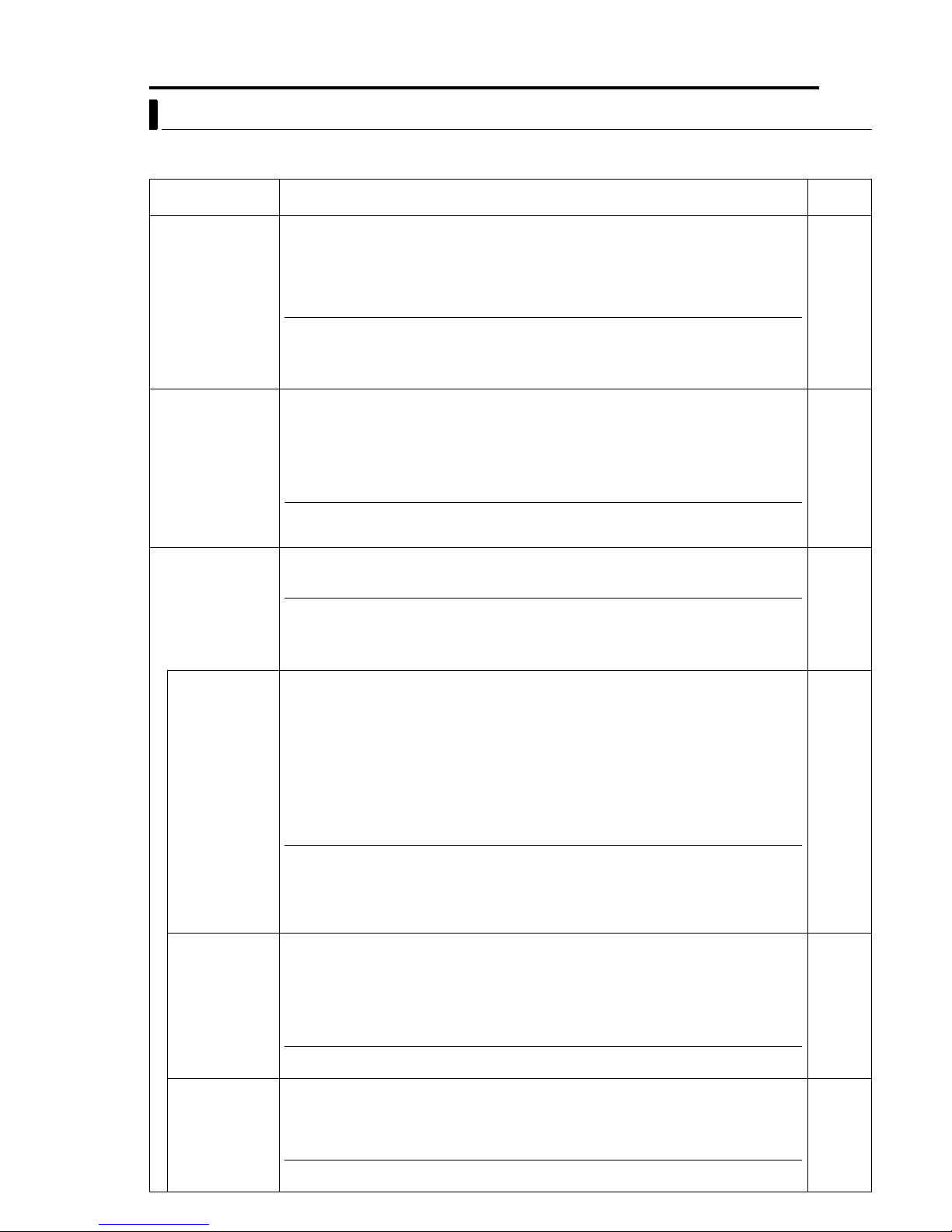
CAMERA TITLE/ALARM Screen
Item Function/Set Value Initial
CAM. TITLE EDIT.. Use this to specify the title that is always displayed at the bottom left of the screen. Specify
up to a maximum of 16 characters. ACAMERA TITLE SetupB (A pg. 34)
AREA DISPLAY Use this to perform area setting.
OFF Not displayed.
TITLE Equally divides the 360° panning range into 16 areas, and a title of up to 16 characters can
DIR
ALARM TITLE SIZE Use this to set the size of the title during an alarm.
ALARM TITLE
EDIT..
ALARM INPUT.. These items are used to perform setting related to the alarm input terminals.
MODE
POLARITY For setting the polarity of alarm input signals.
AAREA DISPLAY Setup (TITLE)B (A pg. 35)
AAREA DISPLAY Setup (DIRECTION)B (A pg. 36)
be specified for each area. The corresponding area title specified will be displayed upon
panning the camera manually. AAREA DISPLAY Setup (TITLE)B (A pg. 35)
Set N (North), which is the direction of the standard axis. When the camera is panned manually,
the 360° panning range will be equally divided into 8 areas, each indicated by N, NE, E, SE, S,
SW, W and NW respectively.
NORMAL: Same size as characters on the menu screen.
DOUBLE: Double the size, both vertically and horizontally, of the characters on the menu screen.
This is a screen for setting the title during an alarm.
AALARM TITLE SetupB (A pg. 37)
For selecting the mode of the camera for which images are to be output when there is an alarm input.
OFF : Does not output images even when there is an alarm input.
HOME : Output images at the home position during an alarm input.
POS1-99 : Output images at a selected preset position during an alarm input.
MEMO
● Setting the AB&W MODEB (A pg. 27) item to AALARM INB switches the mode to the B&W mode and
setting cannot be changed.
MAKE : Input alarm signals when the contact between each alarm input terminal and the
GND terminal changes from open to closed.
BREAK : Input alarm signals when the contact between each alarm input terminal and the
GND terminal changes from closed to open.
A
AREA DISPLAY Setup (DIRECTION)B (Apg. 36)
Val ue
^
OFF
^
DOUBLE
^
OFF
MAKE
MEMO
● This item will be displayed as "- - -" when the AMODEB item is set to AOFFB and setting is not possible.
TIME Use this to set the duration of alarm signal output as well as alarm title display when there is
PRIORITY Sets whether or not manual operation is accepted in case an alarm input is recognized
ALARM OUTPUT.. Use this to perform setting related to the alarm output terminal.
an alarm.
[Set values: 5 s, 6 s, 7 s, 8 s, 9 s, 10 s, 15 s, 20 s, 30 s, 60 s]
8 CAUTION
For RM-P2580 systems, this setting is disabled. Set using the Alarm Time item of RMP2580. (A RM-P2580 AINSTRUCTIONSB)
MEMO
● This item will be displayed as "- - -" when the AMODEB item is set to AOFFB or when the AB&W MODEB
(A pg. 27) item is set to AALARM INB. In both cases, setting will not be possible.
during manual operation of the camera.
ALARM : Manual operation is not accepted when there is an alarm input.
MANUAL : Manual operation is accepted even when there is an alarm input.
8 CAUTION
This item is invalid with a system using the RM-P2580. With this system, the ALARM
input will permanently override manual operation.
OFF : Do not output alarm.
ALARM : Output alarm signals when there is an alarm input.
B&W : Output alarm signals when the camera switches to the B&W mode.
PRESET : Output alarm signals when the camera moves to a preset position.
AUX 1 to AUX 3
(Priority given to alarm)
(Priority given to manual)
:Output alarm signals when there is an auxiliary input.
5 s
ALARM
OFF
Page 27
Setting Up the Camera Using RM-P2580 (continued)
EN 27
CAMERA ALC/VIDEO Screen
This screen enables automatic adjustment according to the brightness. Setting can be performed for the
camera video signals, such as color level and contour enhancement.
Item Function/Set Value
SHUTTER Sets the speed of the electronic shutter.
Set Values
TK-C625E :
TK-C625U :
1/50, 1/120, 1/250, 1/500, 1/1000, 1/2000, 1/4000, 1/10000
1/60, 1/100, 1/250, 1/500, 1/1000, 1/2000, 1/4000, 1/10000
MEMO
● To reduce flickering that occurs under fluorescent lighting, set the shutter speed to 1/100 if your local
power supply frequency is 50 Hz (TK-C625U), and to 1/120 if it is 60 Hz (TK-C625E).
● The higher the shutter speed, the more prominent will be the smear phenomenon. This is a
phenomenon that is characteristic of CCD, whereby white stripes appear at the top and bottom of a
bright light source.
AGC MODE Sets the maximum gain of the AGC (Auto Gain Control), which electronically increases the
gain when the object is under low light conditions.
OFF : Disable AGC.
10 dB : Increase gain by a maximum of 10 dB according to the brightness of the object.
20 dB : Increase gain by a maximum of 20 dB according to the brightness of the object.
MEMO
● When the AB&W MODEB item is set to AAUTOB, the AAGC MODEB item will be automatically set to A20
dBB, and set values cannot be changed.
● The screen may appear grainy at dark places when the gain level is increased.
B&W/COLOUR
For performing setting related to switching between the B&W and Color modes.
MODE..(TK-C625E)
B&W/COLOR
MODE..(TK-C625U)
MEMO
● When in the B&W mode, this camera is sensitive to both visible and near-IR lights. As such, images
may become out of focus upon switching from the Color to B&W mode, depending on the type of light
source used. In this case, re-adjust the focus in the B&W mode. In addition, when the AAF FOR IRB
(A pg. 25) item is set to AONB, focus can be adjusted automatically during mode switching.
● Make use of an IR light as and when necessary.
B&W MODE For setting the function on switching from Color to B&W mode.
COLOUR : Color mode at all times and will not switch to the B&W mode. [For TK-C625U,
this is displayed as ACOLORB.]
B&W : B&W mode at all times.
AUTO :Switches automatically to the Color mode when brightness level of the object is
high, and to the B&W mode when brightness level of the object is low.
ALARM IN : Switches to the B&W mode when there is an alarm input.B&W mode turns ON
when input contact of the camera's input alarm is short (make), and B&W
mode turns OFF when the input contact is open (break).
MEMO
To ensure proper switching between B&W/Color mode
● Switching between the B&W/Color mode can be performed automatically according to the brightness
of the object by setting the AB&W MODEB item to AAUTOB. However, switching may fail depending on
the lighting conditions and angle of view. In order to ensure proper switching, it is recommended that
switching be performed by inputting signals from an external sensor (sold separately) to the alarm
terminal of this camera.
LEVEL For setting the signal level of the object at which switching to the B&W mode is to be
activated when the AB&W MODEB (A pg. 27) item is set to AAUTOB.
LOW : Switch to the B&W mode when signal level of the object is low.
NORMAL : Switch to the B&W mode when signal level of the object is normal.
HIGH : Switch to the B&W mode when signal level of the object is high.
Initial
Val ue
TK-C625E:
1/50
TK-C625U:
1/60
10 dB
^
TK-C625E:
COLOUR
TK-C625U:
COLOR
NORMAL
MEMO
● When the AB&W MODEB item is set to a value other than AAUTOB, "- - -" will be displayed and setting of
the LEVEL item will not be possible.
LIGHT TYPE For setting the type of lighting used for the object when in the B&W mode.
NORMAL : Set to this when a normal light is used.
IR : Set to this when using an infrared emission light.
MEMO
● Switching from the Color to B&W mode may not function correctly if the AIRB setting is used under
ordinary sunlight or fluorescent light.
NORMAL
Page 28

28 EN
Setting Up the Camera Using RM-P2580 (continued)
CAMERA ALC/VIDEO Screen (continued)
Item Function/Set Value
COLOUR LEVEL
(TK-C625E)
COLOR LEVEL
(TK-C625U)
ENHANCE LEVEL Sets the contour enhancement which controls the sharpness on the monitor screen.
PEDESTAL LEVEL Sets the pedestal level (black level) of video signals.
Adjusts the color level of video signals.
To decrease…………… Set a smaller value.
To increase……………. Set a larger value.
[Set values: -5 to NORMAL to 5]
To soften the picture…… Set a smaller value.
To sharpen the picture… Set a larger value.
[Set values: -5 to NORMAL to 5]
To darken the color…………. Set a smaller value.
To brighten the picture……… Set a larger value.
[Set values: -5 to NORMAL to 5]
Initial
Val ue
NORMAL
NORMAL
NORMAL
AUTO PAN/PATROL/TRACE Screen
This screen enables setting of the Auto Pan function, which enables gradual horizontal rotation of the
camera, the Auto Patrol function, which moves the camera to multiple positions in a predetermined
sequence, as well as the Auto Trace function, which reproduces previous manual camera operations.
Item Function/Set Value
AUTO PAN SET.. For setting Auto Pan movements.
AUTO PAN
MODE
AUTO PAN
SPEED
A. PAN POS.
SET..
AUTO PATROL
SET..
MODE For selecting a mode of Auto Patrol movement. [Set values: 1 to 3] 1
POSITION For setting the sequence of patrol positions. The camera will perform Auto Patrol in this
TIME For setting the duration of stop at each position.
AUTO TRACE SET.. For setting Auto Trace movements.
AAUTO PAN SetupB (A pg. 38)
For setting the rotating direction during Auto Pan.
RETURN : Move between the start and end positions
RIGHT : Rightward rotation
LEFT : Leftward rotation
For setting the rotating speed during Auto Pan.
LOW : Rotation at low speed
NORMAL : Rotation at normal speed
HIGH : Rotation at high speed
For setting the start and end positions of Auto Pan when "RETURN" is selected.
For setting Auto Patrol movements.
AAUTO PAT R O L S e t u p B (A pg. 39)
preset sequence of positions.
[Set values: HOME, POSITION1 to 99]
[Set values: SKIP, 10 s, 20 s, 30 s, 45 s, 1 min, 2 min]
AAUTO TRACE SetupB (A pg. 40)
Initial
Val ue
^
RETURN
NORMAL
^
^
^
10 s
^
Page 29

Setting Up the Camera Using RM-P2580 (continued)
Item Function/Set Value
AUTO PAN TRACE/
VIDEO..
IRIS MODE For setting the method of lens iris adjustment.
AVERAGE :
PEAK
BLC MODE
W. BALANCE For setting the white balance adjustment feature. White balance can be adjusted for lighting
R GAIN Adjusts the hue of R (red) when in the AWC mode.
B GAIN Adjusts the hue of B (blue) when in the AWC mode.
RM. A. PAN KEY For setting the action upon pressing the AUTO PAN button on the remote control.
RM. A. PATROL
KEY
For setting video images during Auto Pan and Auto Trace.
AUTO : Adjusts iris automatically to the default state.
AUTO+:Adjusts iris automatically to a level brighter than the default state.
AUTO-:Adjusts iris automatically to a level darker than the default state.
MANUAL : Use this setting to adjust the iris manually.
For setting the method of exposure detection according to the ratio between the average and peak values.
●Larger AVERAGE Value : Use this setting when areas other than those highlighted are
dark and unclear. (Example: 10:0)
●Larger PEAK Value : Use this setting when halation is seen to occur at the
highlighted areas on the screen. (Example: 5:5)
[Set values: 10:0, 9:1, 8:2, 7:3, 6:4, 5:5]
For setting the backlight compensation function. Use this setting when an object appears dark
using the Auto Iris function due to the presence of a bright light source behind the object. Set in
such a way that unnecessary light sources are placed outside the photometry area.
OFF : Do not perform backlight compensation.
AREA 1 to AREA 4 : Set according to the diagram below.
Photometry Area Photometry Area
Photometry
Area
OFF AREA 1 AREA 2 AREA 3 AREA 4
Photometry
測光エリア
Area
Photometry
測光エリア
Area
conditions within a color temperature range of 2,300 K to 10,000 K.
AT W:Auto-Tracking White Balance mode. Adjusts the white balance automatically according
A
to the color temperature of the lighting. During
B
items are displayed as "- - -" and hue adjustment is not possible.
GAIN
AT WB setting, the AR GAINB and AB
AWC:Switches to the Auto White Control mode and a message indicating "Set Start
AWC" will be displayed. Press the SET button to enable the AWC function for white
balance adjustment.
Increase value to enhance the red color.
[Set values: 0 to 255]
Increase value to enhance the blue color.
[Set values: 0 to 255]
A. PAN : Auto Pan function
A. PATROL : Auto Patrol function
A. TRACE : Auto Trace function
For setting the action upon pressing the AUTO PATROL button on the remote control.
A. PAN : Auto Pan function
A. PATROL : Auto Patrol function
A. TRACE : Auto Trace function
EN 29
Initial
Val ue
^
AUTO
8:2
OFF
AT W
^
^
A. PAN
A.
PAT RO L
POS. FUNCTION SET Screen
Use this menu to perform setting related to positions.
Item Function/Set Value
POSITION TITLE.. For setting a title (up to 16 characters) for the preset positions to be displayed on the screen.
APOSITION TITLE SetupB (A pg. 41)
IRIS MODE For setting the method of lens iris adjustment.
AUTO : Adjusts iris automatically to the default state.
AUTO + : Adjusts iris automatically to a level brighter than the default state.
AUTO - : Adjusts iris automatically to a level darker than the default state.
MANUAL : Use this setting to adjust the iris manually.
Initial
Val ue
^
AUTO
Page 30

30 EN
Setting Up the Camera Using RM-P2580 (continued)
POS. FUNCTION SET Screen (continued)
Item Function/Set Value
AVERAGE : PEAK For setting the method of exposure detection according to the ratio between the average and
peak values.
●Larger AVERAGE Value : Use this setting when areas other than those highlighted are
●Larger PEAK Value : Use this setting when halation is seen to occur at the
[Set values: 10:0, 9:1, 8:2, 7:3, 6:4, 5:5]
BLC MODE
W. BALANCE For setting the white balance adjustment feature. White balance can be adjusted for lighting
R GAIN Adjusts the hue of R (red) when in the AWC mode.
B GAIN Adjusts the hue of B (blue) when in the AWC mode.
For setting the backlight compensation function. Use this setting when an object appears dark
using the Auto Iris function due to the presence of a bright light source behind the object. Set in
such a way that unnecessary light sources are placed outside the photometry area.
OFF : Do not perform backlight compensation.
AREA 1 to AREA 4 : Set according to the diagram below.
Photometry
Area
OFF AREA 1 AREA 2 AREA 3 AREA 4
conditions within a color temperature range of 2,300 K to 10,000 K.
AT W:Auto-Tracking White Balance mode. Adjusts the white balance automatically according
AWC:Switches to the Auto White Control mode and a message indicating A<SET> AWC
Increase value to enhance the red color.
[Set values: 0 to 255]
Increase value to enhance the blue color.
[Set values: 0 to 255]
to the color temperature of the lighting. During
B
items are displayed as "- - -" and hue adjustment is not possible.
GAIN
EXECB will be displayed. Press the SET button to enable the AWC function for white
balance adjustment.
dark and unclear. (Example: 10:0)
highlighted areas on the screen. (Example: 5:5)
Photometry Area P hotometry Area
Photometry
測光エリア
A
AT WB setting, the AR GAINB and AB
Photometry
測光エリア
Initial
Val ue
8:2
OFF
AT W
^
^
FACTORY SETTINGS Screen
Use this screen to restore the values set in the menu to their factory settings.
Item Function/Set Value
CANCEL Do not restore to factory settings. Press the MENU button or the SET button to return to the
CLEAR
(W/O POS. TITLE)
CLEAR (ALL) Upon pressing the SET button, a message indicating AFACTORY SETTINGS...B will be
menu screen.
Restore factory settings. Upon pressing the SET button, a message indicating AFACTORY
SETTINGS...B will be displayed for approximately 20 seconds, upon which the set values will
be restored to their factory settings. Upon completion, a message indicating ADATA
CLEAREDB will appear.
Preset positions as well as settings and titles for each position, however, will not be restored
to their initial values. Returns to the menu screen upon completion.
displayed for approximately 20 seconds, upon which the set values will be restored to their
factory settings. Upon completion, a message indicating ADATA CLEAREDB will appear.
All settings including the titles and preset positions will be restored to their initial values.
Returns to the menu screen upon completion.
Initial
Val ue
^
Page 31

Setting Up the Camera Using RM-P2580 (continued)
PRIVATE MASK Setup
EN 31
MENU button
SET button
CAMERA button
AF
POWER
ALARM
KEYLOCK
OPEN
FAR
TELE CLEAR
CAMERA POSITION
1
4
7
Numeric
keys
SETUP
MENU SET
CLOSE
NEAR
WIDE
SPEED
IRIS
FOCUS
ZOOM
TELE
button
WIDE button
CAMERA FUNCTION1
V. PHASE - - POS. TITLE LOC. UP-L
PRIVATE MASK..
MANUAL DISPLAY ON
MENU>EXIT<SET>SUB MENU
<
CAM. FUNCTION 1 screen
PRIVATE MASK
MODE OFF
MASK No. 1 (M)
MASK EDIT ..
MASK DELETE ..
MENU>RETURN
<
PRIVATE MASK screen
MENU>RETURN
<
MASK EDIT screen
CAMERA/POSITION
3
2
6
5
9
8
0
ENTER
/HOME
MASK EDIT
CAMERA
POSI-
TION
OPTION1OPTION
2
AUTO
AUTO
PAN
PATROL
ENTER
button
PA N lever
REMOTECONTROL UNIT
AUTO F-1 F-2 F-3
PAN/TILTLENS
RM-P2580
Already
set.
Use the PRIVATE MASK screen to set up the private mask
function, which grays out areas that are not required to be
included in the monitored picture. Up to four private masks
can be set per screen, and up to eight private masks can be
set in total.
1 Select the camera. (A RM-P2580 AINSTRUCTIONSB)
CAMERA buttonNNumeric key (Camera Number)NENTER button
●The picture of the selected camera is output.
2 Display the MENU screen. (A pg. 21, steps 2 to 4)
MENU button (3 sec.) N Select ACAMERA..B using the PA N lever N
SET button.
●The AMENUB screen will be displayed.
3 Tilt the PAN lever up or down to move the cursor (E) to
ACAM. FUNCTION 1..B and press the SET button.
●The ACAMERA FUNCTION 1B screen is displayed.
4 Move the cursor (E) to APRIVATE MASK..B and press the SET
button.
The APRIVATE MASKB screen is displayed.
5 Select the private mask function ON or OFF.
Tu rn the private mask function on or off by setting the AMODEB item in
the submenu to ON or OFF (Factory setting: OFF)
6 Select the mask number.
Select the private mask number from MASK No. 1 to No. 8 and move the
cursor to the item AMASK EDIT..B. A maximum of 4 can be set within one
picture.
If an already set mask number is selected, the (M) mark will be
displayed.
7 Edit the masking area.
●Move the cursor to AMASK EDIT..B and press the SET button to display
the AMASK EDITB screen. (The masked area will be displayed as a
grayed-out area.)
●Tilt the PAN lever to move the grayed-out area to the center of the area
to be masked.
●Press the TELE button and WIDE button to set the masked area size.
8 CAUTIONS
●It is not possible to set five or more masks in adjacent areas. (Even
when this is attempted, the masked area that is required to be set will
not be displayed.)
●MASK cannot be set at lower than approx. 40
° in the horizontal
direction. (The masks for new settings are not displayed.)
8 Press the MENU button.
●The screen returns to the APRIVATE MASKB screen.
●To delete a private mask area, select AMASK DELETE..B, move the
cursor to ADELETEB and press the SET button. The PRIVATE MASK
menu reappears after the data has been deleted.
●To cancel deletion, select ACANCELB and press the SET button.
9 Repeat steps 6 to 8 for each additional mask area.
10 Press the MENU button.
The screen returns to the ACAMERA FUNCTION 1B menu.
8 CAUTIONS
●There may be cases, depending on the camera direction and zoom position, in which an object is captured from within the
private mask area. After setting the private mask, be sure to vary the camera direction and zoom position in order to confirm
that the camera does not capture objects from within this area.
●The Private Mask function cannot be carried out during the initializing process immediately after the power is turned on.
●When 4 masking areas are set within the same screen, setting of another mask in an adjacent area may fail. In this case,
adjust the angle of view settings.
●When 4 marks are set on one same screen, the next mark might not be possible to set on the nearest area. In that case, set
the angle of screen again.
Page 32
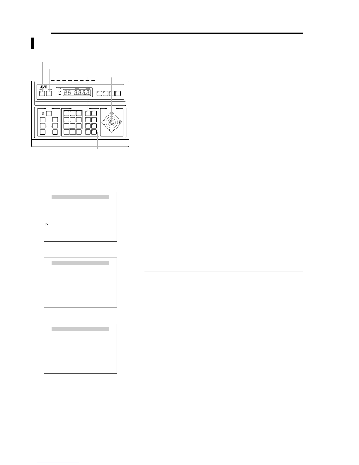
32 EN
Setting Up the Camera Using RM-P2580 (continued)
MANUAL PAN LIMIT Setup
MENU button
SET button
CAMERA button
AF
POWER
ALARM
KEYLOCK
OPEN
FAR
TELE CLEAR
CAMERA POSITION
CAMERA/POSITION
2
1
4
5
7
8
0
/HOME
SETUP
MENU SET
CLOSE
NEAR
WIDE
SPEED
IRIS
FOCUS
ZOOM
Numeric
keys
CAMERA FUNCTION2
FLIP OFF
VAR.P/T SPEED ON
EASY AF OFF
AF FOR IR OFF
TILT LIMIT
M. PAN LIMIT.. ON
AUTO RETURN..
MENU>RETURN
<
CAMERA
3
OPTION1OPTION
6
9
ENTER
SET>SUB MENU
<
POSITION
2
AUTO
AUTO
PAN
PATROL
ENTER
button
PA N lever
REMOTECONTROL UNIT
AUTO F-1 F-2 F-3
CAMERA FUNCTION 2 Screen
M. PAN LIMIT POS.SET
[L]POS.SETTING
SET>INVALID
<
DURING PAN MOVEMENT
MENU>RETURN<SET>L/R
<
→
M. PAN LIMIT POS.SET Screen (Left Limit)
M. PAN LIMIT POS.SET
This section describes procedures for setting the Panning
(horizontal) range during manual operation.
1 Select a camera. (ARM-P2580 AINSTRUCTIONSB)
RM-P2580
CAMERA buttonNNumeric key (Camera Number)NENTER button
●Video images of the selected camera will be output.
2 MENU screen display. (A pg. 21, steps 2 to 4)
MENU button (3 sec.) N Select ACAMERA..B using the PA N lever N
PAN/TILTLENS
SET button.
●The AMENUB screen will be displayed.
3 Move the PAN lever upward/downward to shift the cursor (E)
to the ACAM. FUNCTION 2..B item, followed by pressing the
SET button.
●The ACAMERA FUNCTION 2B screen will be displayed.
4 Shift the cursor (E) to the AM. PAN LIMIT..B item, and move
the PAN lever leftward/rightward to select AONB.
5 Press the SET button.
●The AM. PAN LIMIT POS.SETB screen (left limit) will be displayed.
6 Set the position for the left limit.
Use the PA N lever to determine the position for the left limit.
●During setting, a message indicating A[L] POS. SETTING NB will be
displayed at the bottom left of the screen.
7 Press the SET button.
●The screen will switch to the right limit setting screen.
8 Set the position for the right limit.
Use the PA N lever to determine the position for the right limit.
●During setting, a message indicating AO [R] POS. SETTINGB will be
displayed at the bottom right of the screen.
9 Press the MENU button.
●This stores the limit positions that have been set and returns the
screen to the ACAMERA FUNCTION 2B menu.
MEMO
● Tilting , zooming and focusing operations are possible when this menu is displayed.
● If a pan limit has already been set, the camera will move to the left pan limit position
when this menu is invoked.
● Setting cannot be performed when Panning is in progress. Press the SET button
after Panning has come to a stop.
● Auto Flip operation will override this setting if the destination position of Auto Flip is
outside the range as set in this item.
● Manual Pan Limit remains valid when setting preset positions.
Movement to preset positions will be performed without regard to the Manual Pan Limit.
●
● The AM. PAN LIMIT..B item will not affect the following even when it is set to AONB.
•PRIVATE MASK Settings
•AUTO PAN POSITION Settings
•AREA DISPLAY Settings
←
[R]POS.SETTING
SET>INVALID
<
DURING PAN MOVEMENT
MENU>RETURN<SET>L/R
<
M. PAN LIMIT POS.SET Screen (Right Limit)
Page 33

Setting Up the Camera Using RM-P2580 (continued)
MANUAL PAN LIMIT Setup (continued)
8 Basic operation of Manual Pan Limit
Right Limit Invalid Range
V
a
l
i
d
e
g
n
a
R
Left Limit
●Panning operation will only be allowed within the valid range upon
setting the Manual Pan Limit.
●When the camera is moved by an operation that overrides the Manual
Pan Limit into a region outside the valid panning range, the camera will
function as follows when a manual Pan operation is performed.
●Pan operations can be freely performed outside the panning range until
the camera enters the valid range again.
●Upon entering the valid range, Pan operation will only be possible
within the Manual Pan Limit that has been set.
8 Operations that override the Manual Pan Limit
The following operations are performed without regard to the invalid
range as set by the Manual Pan Limit.
●Auto Pan operation
●Auto Trace operation
●Movement to preset positions
●Auto Flip operation
8 Settings that override the Manual Pan Limit
The following settings involve Pan operations but setting can be performed
without regard to the invalid range as set by the Manual Pan Limit.
●PRIVATE MASK Setup
●AUTO PAN Setup
●AREA DISPLAY Setup (TITLE)
●AREA DISPLAY Setup (DIRECTION)
EN 33
MEMO
● If the AM. PAN LIMIT..B is AONB during setting of Auto Trace and preset positions,
Pan operation within the invalid range will not be possible. However, since Auto
Tr ace and movement to preset positions are operations that override the Manual
Pan Limit, panning within the invalid range of the Manual Pan Limit is possible if
setting of Auto Trace and preset positions are performed prior to the MANUAL PAN
LIMIT setup.
Page 34

34 EN
Setting Up the Camera Using RM-P2580 (continued)
CAMERA TITLE Setup
MENU button
SET button
CAMERA button
AF
POWER
ALARM
KEYLOCK
OPEN
FAR
TELE CLEAR
CAMERA POSITION
CAMERA/POSITION
2
1
4
5
7
8
0
/HOME
Numeric
keys
SETUP
MENU SET
CLOSE
NEAR
WIDE
SPEED
IRIS
FOCUS
ZOOM
TELE
button
WIDE button
cursor
CAM.FUNCTION1..
CAM.FUNCTION2..
CAM.TITLE/ALARM..
CAM.ALC/VIDEO..
AUTO PAN/PATROL/TRACE..
POS.FUNCTION SET..
FACTORY SETTINGS..
MENU>EXIT<SET>SUB MENU
<
MENU
MENU Screen
CAMERA TITLE / ALARM
CAM.TITLE EDIT..
AREA DISPLAY OFF
ALARM TITLE SIZE DOUBLE
ALARM TITLE EDIT..
ALARM INPUT..
ALARM OUTPUT..
MENU>RETURN<SET>SUB MENU
<
CAMERA TITLE/ALARM Screen
Use the CAMERA TITLE screen to set the title of each
camera. Titles can be up to 16 characters in length and are
PA N lever
REMOTECONTROL UNIT
AUTO F-1 F-2 F-3
RM-P2580
displayed at the bottom left of the picture.
1 Select the camera. (A RM-P2580 AINSTRUCTIONSB)
CAMERA buttonNNumeric key (Camera Number)NENTER button
●The picture of the selected camera is output.
2 Display the MENU screen. (A pg. 21, steps 2 to 4)
CAMERA
3
OPTION1OPTION
6
AUTO
9
PAN
ENTER
PAN/TILTLENS
POSITION
2
AUTO
PATROL
ENTER
button
MENU button (3 sec.) N Select ACAMERA..B using the PA N lever N
SET button.
●The AMENUB screen will be displayed.
3 Tilt the PAN lever up or down to move the cursor (E) to
ACAMERA TITLE/ALARM..B and press the SET button.
●The ACAMERA TITLE/ALARMB menu is displayed.
4 Ensure that the cursor (E) is located on ACAMERA TITLE
EDIT..B and press the SET button.
●The ACAMERA TITLE EDITB screen is displayed.
●The first character appears blinking and input is enabled.
5 Use the PAN lever to select the first character of the title
from the character area.
●The selected character will appear blinking.
6 Press the SET button.
●The first character of the title is now confirmed, and input of the
second character is possible.
●If the WIDE button is pressed, the title input field moves to the left. Use
this to correct previously input characters.
7 Repeat steps 5 and 6 for each title character.
Complete the input of the title for the selected camera in the same way.
8 Press the MENU button.
●This stores the camera title that has been set and returns the screen to
the previous menu.
●To set the titles for multiple cameras, repeat steps 1 to 7 for each
camera.
MEMO
●Only displayed for the TK-C625E model.
Space Blinking Character area
CAMERA TITLE EDIT
0123456789ABCDEFGHIJKLMNO
PQRSTUVWXYZabcdefghijklmno
pqrstuvwxyzДЦЬКОФЫЗСдлпць
вкофыбйнуъаимтщзсЯ¡¿ . , ’ - : /
() <>
CLRCANCEL [][]INSDEL
MENU>RETURN<SET>CHAR .SET
<
[]
WT
A MENO
Title input
field
CAMERA TITLE EDIT Screen
Page 35

Setting Up the Camera Using RM-P2580 (continued)
AREA DISPLAY Setup (TITLE)
This section describes procedures to display area titles on the
screen, when the 360° panning (horizontal) range is divided
into 16 areas and when the camera is manually rotated. Title
for each area can be specified up to 16 characters. (Turning
ON/OFF Area Title display AAREA DISPLAYB (A pg. 26))
1 Select a camera. (ARM-P2580 AINSTRUCTIONSB)
AREA
2
MENU button
SET button
CAMERA button
SETUP
POWER
ALARM
MENU SET
KEYLOCK
SPEED
IRIS
OPEN
CLOSE
FOCUS
FAR
NEAR
AF
TELE CLEAR
WIDE
ZOOM
TELE
button
WIDE button
NEAR button
CAM.FUNCTION1..
CAM.FUNCTION2..
CAM.TITLE/ALARM..
CAM.ALC/VIDEO..
AUTO PAN/PATROL/TRACE..
POS.FUNCTION SET..
FACTORY SETTINGS..
MENU>EXIT<SET>SUB MENU
<
AREA
AREA
1
HOME
POSITION
CAMERA POSITION
CAMERA/POSITION
/HOME
2
5
8
0
3
6
9
ENTER
MENU
CAMERA
OPTION1OPTION
AUTO
PAN
ENTER
button
1
4
7
FAR
button
MENU Screen
16
POSI-
TION
AUTO
PATROL
EA
AR
15
PA N l eve r
REMOTECONTROL UNIT
AUTO F-1 F-2 F-3
2
Numeric
keys
RM-P2580
PAN/TILTLENS
CAMERA buttonNNumeric key (Camera Number)NENTER button
●Video images of the selected camera will be output.
2 Display the MENU screen. (A pg. 21, steps 2 to 4)
MENU button (3 sec.) N Select ACAMERA..B using the PA N lever N
SET button.
●The AMENUB screen will be displayed.
3 Move the PAN lever upward/downward to shift the cursor (E)
to the ACAM. TITLE/ALARM..B item, followed by pressing the
SET button.
●The ACAMERA TITLE/ALARMB screen will be displayed.
4 Shift the cursor (E) to the AAREA DISPLAYB item, move the
PAN lever leftward/rightward to select the ATITLEB, followed
by pressing the SET button.
●The AAREA TITLE EDIT AREA 1B screen will be displayed. (Home
position corresponds to AREA 1)
●The first character appears blinking and input is enabled.
5 Move the PAN lever upward/downward or leftward/rightward
to select the first character to input.
●The selected character will appear blinking.
6 Press the SET button.
●The first character of the title is now confirmed and input of the
second character is possible.
●Press the WIDE button to move the blinking cursor in the Title Input
Field leftward. Use this when amending the set title.
7 Press the FAR button.
●The camera moves to the next area and the AAREA TITLE EDIT
AREA 2B screen will be displayed.
●Press the NEAR button to return to the previous area . The previous
AAREA TITLE EDIT AREA 1B screen will be displayed.
8 Repeat Steps 5 to 7.
●Repeat procedure to enter a title for each area. (AREA 1 to AREA 16)
9 Press the MENU button.
●The set area title will be stored and the screen will return to the
previous menu.
EN 35
CAMERA TITLE / ALARM
CAM.TITLE EDIT..
AREA DISPLAY.. TITLE
ALARM TITLE SIZE DOUBLE
ALARM TITLE EDIT..
ALARM INPUT..
ALARM OUTPUT..
MENU>RETURN<SET>SUB MENU
<
Space Blinking Character area
AREA TITLE EDIT AREA∗ ∗
0123456789ABCDEFGHIJKLMNO
PQRSTUVWXYZabcdefghijklmno
pqrstuvwxyzДЦЬКОФЫЗСдлпць
вкофыбйнуъаимтщзсЯ¡¿.,’-:/
() <>
CLRCANCEL [][]INSDEL
FOCUS KEY>AREA No . SELECT
<
MENU>RETURN<SET>CHAR .SET
<
[]
WT
ALARM TITLE EDIT Screen
MEMO
● Only displayed for the TK-C625E model.
A MENO
Title input
field
Page 36

36 EN
Setting Up the Camera Using RM-P2580 (continued)
AREA DISPLAY Setup (DIRECTION)
Upon setting N (North), which is the standard axis, the 360°
panning range will be equally divided into 8 areas. Perform
SE
SW
manual panning of the camera and each area will be
displayed as N, NE, E, SE, S, SW, W, NW.
E
NE
MENU button
SET button
CAMERA button
AF
POWER
ALARM
KEYLOCK
OPEN
FAR
TELE CLEAR
CAMERA POSITION
1
4
7
SETUP
MENU SET
CLOSE
NEAR
WIDE
SPEED
IRIS
FOCUS
ZOOM
Numeric
keys
CAM.FUNCTION1..
CAM.FUNCTION2..
CAM.TITLE/ALARM..
CAM.ALC/VIDEO..
AUTO PAN/PATROL/TRACE..
POS.FUNCTION SET..
FACTORY SETTINGS..
MENU>EXIT<SET>SUB MENU
<
MENU Screen
N
CAMERA/POSITION
2
3
5
6
8
9
0
ENTER
/HOME
MENU
CAMERA
OPTION1OPTION
AUTO
PAN
PATROL
ENTER
button
NW
REMOTECONTROL UNIT
AUTO F-1 F-2 F-3
POSITION
2
AUTO
WestEast
W
PA N lever
RM-P2580
PAN/TILTLENS
1 Select a camera. (ARM-P2580 AINSTRUCTIONSB)
CAMERA buttonNNumeric key (Camera Number)NENTER button
●Video images of the selected camera will be output.
2 Display the MENU screen. (A pg. 21, steps 2 to 4)
MENU button (3 sec.) N Select ACAMERA..B using the PAN lever NSET
button.
●The AMENUB screen will be displayed.
3 Move the PAN lever upward/downward to shift the cursor (E)
to the ACAM. TITLE/ALARM..B item, followed by pressing the
SET button.
●The ACAMERA TITLE/ALARMB screen will be displayed.
4 Shift the cursor (E) to the AREA DISPLAY item, and move
the PAN lever leftward/rightward to select ADIRB.
5 Press the SET button.
●The ADIRECTION STANDARD AXISB screen will be displayed.
6 Move the PAN lever leftward/rightward to set the direction
(N) of the standard axis.
7 Press the MENU button.
●This sets the start position of the direction axis, which will be displayed
on the top left of the screen.
●Directions are displayed as N (north), NE (north-east), E (east), SE
(south-east), S (south), SW (south-west), W (west) and NW (northwest) respectively.
MEMO
● Tilting, zooming and focusing operations are possible when this menu is displayed.
● If a start position for the direction axis has already been set, the camera will move
to this start position when this menu is invoked.
CAMERA TITLE / ALARM
CAM.TITLE EDIT..
AREA DISPLAY.. DIR
ALARM TITLE SIZE DOUBLE
ALARM TITLE EDIT..
ALARM INPUT..
ALARM OUTPUT..
MENU>RETURN<SET>SUB MENU
<
CAMERA TITLE/ALARM Screen
DIRECTION STANDARD AXIS
SET UP STANDARD AXIS (N)
MENU>RETURN
<
DIRECTION STANDARD AXIS Screen
Page 37

Setting Up the Camera Using RM-P2580 (continued)
ALARM TITLE Setup
EN 37
MENU button
SET button
CAMERA button
3
6
9
REMOTECONTROL UNIT
CAMERA
POSI-
TION
OPTION1OPTION
2
AUTO
AUTO
PAN
PATROL
ENTER
button
AUTO F-1 F-2 F-3
SETUP
MENU SET
CLOSE
NEAR
WIDE
FOCUS
SPEED
IRIS
AF
ZOOM
POWER
ALARM
KEYLOCK
OPEN
FAR
TELE CLEAR
FAR
button
CAMERA POSITION
CAMERA/POSITION
2
1
4
5
7
8
0
ENTER
/HOME
Numeric
keys
WIDE button
NEAR button
CAM.FUNCTION1..
CAM.FUNCTION2..
CAM.TITLE/ALARM..
CAM.ALC/VIDEO..
AUTO PAN/PATROL/TRACE..
POS.FUNCTION SET..
FACTORY SETTINGS..
MENU>EXIT<SET>SUB MENU
<
MENU
MENU Screen
CAMERA TITLE / ALARM
CAM.TITLE EDIT..
AREA DISPLAY OFF
ALARM TITLE SIZE DOUBLE
ALARM TITLE EDIT..
ALARM INPUT..
ALARM OUTPUT..
MENU>RETURN<SET>SUB MENU
<
CAMERA TITLE/ALARM Screen
Space Blinking Character area
PA N lever
RM-P2580
PAN/TILTLENS
Use the ALARM TITLE screen to set the alarm titles to be displayed
when an alarm signal is transmitted. Up to 10 alarm titles (ALARM TITLE
1 to 10) can be set and each title can be up to 12 characters in length.
1 Select the camera. (A RM-P2580 AINSTRUCTIONSB)
CAMERA buttonNNumeric key(Camera Number)NENTER button
●The picture of the selected camera is output.
2 Display the MENU screen. (A pg. 21, steps 2 to 4)
MENU button (3 sec.) N Select ACAMERA..B using the PA N lever N
SET button.
●The AMENUB screen will be displayed.
3 Tilt the PAN lever up or down to move the cursor (E) to
ACAM. TITLE/ALARM..B and press the SET button.
●The ACAMERA TITLE/ALARMB screen is displayed.
4 Move the cursor (E) to the AALARM TITLE EDIT..B item and
press the SET button.
●The AALARM TITLE EDIT No.1B screen will be displayed.
●The first character appears blinking and input is enabled.
5 Use the PAN lever to select the first character of the title
from the character area.
●The selected character will appear blinking.
●The selected character is displayed in the title input field.
6 Press the SET button.
●The first character of the title is now confirmed, and input of the second
character is possible.
●If the WIDE button is pressed, the title input field moves to the left. Use
this to correct previously input characters.
7 Press the FAR button.
●The next AALARM TITLE EDIT No.2B screen is displayed.
●If the NEAR button is pressed, the previous AALARM TITLE EDIT No.1B
screen is displayed.
8 Repeat steps 5 to 7 for each alarm title.
Complete the input of all the alarm titles (AALARM TITLE EDITB 1 to 10)
in the same way.
9 Press the MENU button.
●The screen returns to the previous menu.
MEMO
● Only displayed for the TK-C625E model.
ALARM TITLE EDIT No.∗ ∗
0123456789ABCDEFGHIJKLMNO
PQRSTUVWXYZabcdefghijklmno
pqrstuvwxyzДЦЬКОФЫЗСдлпць
вкофыбйнуъаимтщзсЯ¡¿ . , ’ - : /
() <>
CLRCANCEL [][]INSDEL
FOCUS KEY>ALARM No . SELECT
<
MENU>RETURN<SET>CHAR .SET
<
[]
WT
ALARM TITLE EDIT Screen
RM-P2580 units need to be configured to display alarm titles. Use the RM-P2580 menu settings to do this:
A Press and hold the MENU button for 3 seconds to display the SETUP screen on the remote control unit.
B First select the ACONTROL UNIT..B screen, then the ADATA I/OB screen and finally the AINPUT ASSIGNMENTB screen.
C Select AALARM TEXTB then AEDIT 1B, the alarm title set as AALARM TITLE EDIT 1B is displayed on the monitor.
* The alarm signals are input into the DATA I/O terminals on the rear panel of the RM-P2580.
A MENO
Title input
field
Page 38
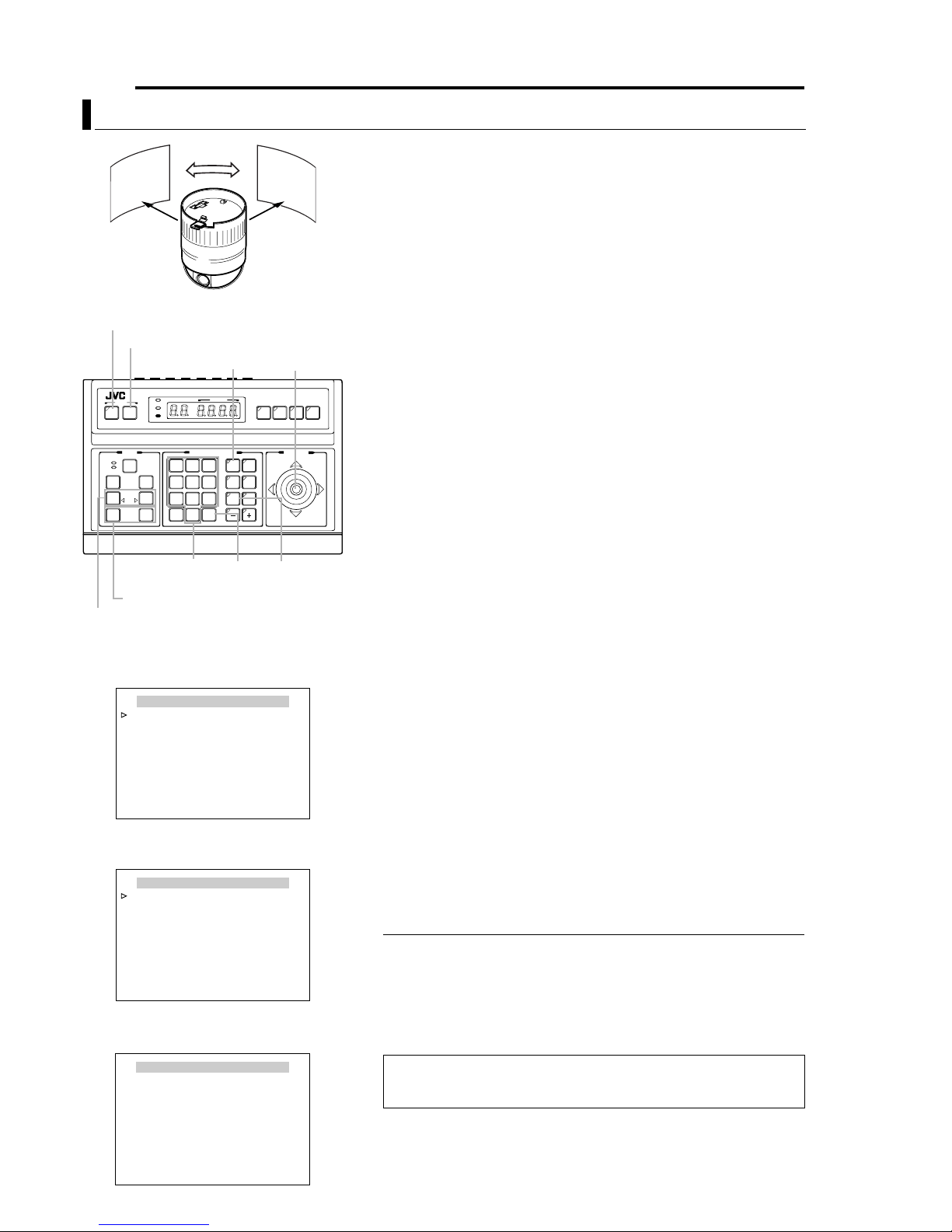
38 EN
Setting Up the Camera Using RM-P2580 (continued)
AUTO PAN Setup
Gradual Rotation
Image of
start position
MENU button
SET button
CAMERA button
AF
POWER
ALARM
KEYLOCK
OPEN
FAR
TELE CLEAR
CAMERA POSITION
CAMERA/POSITION
3
2
1
4
6
5
7
9
8
0
ENTER
/HOME
SETUP
MENU SET
CLOSE
NEAR
WIDE
SPEED
IRIS
FOCUS
ZOOM
Numeric
keys
ZOOM button
FOCUS button
AUTO PAN / PATROL / TRACE
AUTO PAN SET..
AUTO PATROL SET..
AUTO TRACE SET..
AUTO PAN / TRACE VIDEO ..
RM.A.PAN KEY A.PAN
RM.A.PATROL KEY A . PATROL
MENU>RETURN<SET>SUB MENU
<
AUTO PAN/PATROL/TRACE screen
AUTO PAN SET
AUTO PAN MODE RETURN
AUTO PAN SPEED NORMAL
A.PAN POS . SET..
MENU>RETURN
<
AUTO PAN SET screen
CAMERA
POSITION
OPTION1OPTION
2
AUTO
AUTO
PAN
PATROL
ENTER
button
Image of
end position
PA N lever
REMOTECONTROL UNIT
AUTO F-1 F-2 F-3
PAN/TILTLENS
AUTO PAN
button
RM-P2580
This section describes procedures for setting the Auto Pan
function, which enables gradual horizontal rotation of the
camera. There are 3 Auto Pan modes, namely movement
between 2 points, rightward rotation and leftward rotation.
1 Select camera. (ARM-P2580 AINSTRUCTIONSB)
CAMERA buttonNNumeric key (Camera Number)NENTER button
●Video images of the selected camera will be output.
2 Display the MENU screen. (A pg. 21, steps 2 to 4)
MENU button (3 sec.) N Select ACAMERA..B using the PAN lever NSET
button.
●The AMENUB screen will be displayed.
3 Move the PAN lever upward/downward to shift the cursor (E)
to the AAUTO PAN/PATROL/TRACE..B item, followed by
pressing the SET button.
●The AAU TO PAN/PAT R O L/ T R AC E B screen will be displayed.
4 Press the SET button.
●Check that the cursor is at the AAUTO PAN SET..B item and press SET
button.
5 Set the AUTO PAN MODE and AUTO PAN SPEED.
●Set the type of Auto Pan movement using the AUTO PAN MODE item.
RETURN (Movement between 2 points), RIGHT and LEFT
●Set the rotating speed of Auto Pan using the AUTO PAN SPEED item.
LOW, NORMAL, HIGH
6 Shift the cursor (E) to the AA. PAN POS. SET..B item, and
press the SET button (only when in the Return mode).
●The AAU TO PAN POSITION SETB screen will be displayed.
7 Adjust the angle of view at the start position (only when in
the RETURN mode).
●Use the PA N lever, FOCUS button and ZOOM button for adjustment.
●Tilting operations or lens operations such as focusing and zooming are
not possible at the return position.
●During setting, a message indicating A[START] POS.SET NB will be
displayed at the bottom left of the screen.
8 Press the SET button (only when in the RETURN mode).
This switches the start position to the end position.
9 Set the end position (only when in the RETURN mode).
●Set the return position using the PA N lever.
●During setting, a message indicating AO [END] POS.SETB will be
displayed at the bottom right of the screen.
10 Press the MENU button.
The Auto Pan position that has been set will be stored and the screen
will return to the previous menu (AAU TO PA N SETB screen).
MEMO
● Ve rtical movement (tilting) and lens operations are not possible at the return
position.
● Writing of preset data may fail if the SET button or MENU button is pressed when
the camera is moving. Ensure that the camera has come to a stop before pressing
the SET button and MENU button.
● The Manual Pan Limit mode will be temporarily turned OFF when this menu is
displayed. Manual Pan Limit can be set upon exiting this menu without affecting the
Auto Pan operation.
AUTO PAN POSITION SET
[START] POS.SET
SET>INVALID
<
DURING PAN MOVEMENT
MENU>RETURN<SET>L/R
<
→
AUTO PAN POSITION SET screen
To enable Auto Pan operation upon setting, press the AUTO PAN button
on RM-P2580.
A RM-P2580 "Auto Pan operation", INSTRUCTIONS
Page 39

Setting Up the Camera Using RM-P2580 (continued)
AUTO PATROL Setup
EN 39
High
speed
POSITION
POSITION
1
POSITION
4
MENU button
SET button
CAMERA button
SETUP
POWER
ALARM
MENU SET
KEYLOCK
SPEED
IRIS
OPEN
CLOSE
FOCUS
FAR
NEAR
AF
TELE CLEAR
WIDE
ZOOM
TELE
button
WIDE button
NEAR button
AUTO PAN / PATROL / TRACE
AUTO PAN SET..
AUTO PATROL SET..
AUTO TRACE SET..
AUTO PAN / TRACE VIDEO ..
RM.A.PAN KEY A.PAN
RM.A.PATROL KEY A . PATROL
MENU>RETURN<SET>SUB MENU
<
AUTO PAN/PATR OL / T R AC E S c r e e n
AUTO PATROL SET MODE 1
PATROL 1 HOME 10s
PATROL 2 POS 1 10s
PATROL 3 POS 2 10s
PATROL 4 POS 3 10s
PATROL 5 POS 4 10s
PATROL 6 POS 5 10s
PATROL 7 POS 6 10s
PATROL 8 POS 7 10s
FOCUS>MODE<ZOOM>PAGE
<
MENU>RETURN
<
AUTO PATROL SET MODE 1 Screen
(Example showing PATROL Nos.1 to 8)
AUTO PATROL SET MODE 1
PATROL 9 POS 8 10s
PATROL 10 POS 9 10s
PATROL 11 POS 10 10s
PATROL 12 POS 11 10s
PATROL 13 POS 12 10s
PATROL 14 POS 13 10s
PATROL 15 POS 14 10s
PATROL 16 POS 15 10s
FOCUS>MODE<ZOOM>PAGE
<
MENU>RETURN
<
AUTO PATROL SET MODE 1 Screen
(Example showing PATROL Nos. 9 to 16)
High
speed
CAMERA POSITION
CAMERA/POSITION
2
3
1
5
6
4
8
7
9
0
ENTER
/HOME
FAR
button
POSITION
POSITION button
REMOTECONTROL UNIT
CAMERA
POSI-
TION
OPTION1OPTION
2
AUTO
AUTO
PAN
PATROL
ENTER
button
2
High speedHigh speed
3
PA N lever
RM-P2580
AUTO F-1 F-2 F-3
PAN/TILTLENS
AUTO
PAT RO L
button
Use the AUTO PATROL screen to set the configuration of the
Auto Patrol function, which moves the camera between
several positions at a high speed. Patrol positions 1-100 can
be set in each of three modes (MODES 1 to 3). It is
recommended that these three modes be set according to the
day of the week or the time of day. For example: MODE 1 for
nighttime and MODE 2 for daytime.
1 Select the camera. (A RM-P2580 AINSTRUCTIONSB)
CAMERA buttonNNumeric key (Camera Number)NENTER button
●The picture of the selected camera is output.
2 Display the MENU screen. (A pg. 21, steps 2 to 4)
MENU button (3 sec.) N Select ACAMERA..B using the PAN lever NSET
button.
●The AMENUB screen will be displayed.
3 Tilt the PAN lever up or down to move the cursor (E) to
AAUTO PAN/PATROL/TRACE..B and press the SET button.
●The AAUTO PAN/PATROL/TRACE..B screen is displayed.
4 Move the cursor (E) to AAUTO PATROL SET..B and press the
SET button.
●The AAUTO PATROL SET MODE 1B screen is displayed.
5 Tilt the PAN lever to move the cursor (E) to the PATROL
position to be set.
●To display the next page (PATROL positions 9 to 19), press the TELE
button.
●To display the previous page, press the WIDE button.
6 Set a patroll position.
POSITION buttonNNumeric key (position number) N ENTER button
●Po sitions from PATROL 1 to 100 are set in the order of HOME, followed
by POS 1 to POS 99.
7 Set the length of time a camera will stay in each position.
●Use the PA N lever to the left or right to set the time period.
●Available set values: SKIP, 10s, 20s, 30s, 45s, 1min, 2min. (Selecting
ASKIPB skips that position and moves to the next position.)
●The factory setting is 10s for all positions.
8 Repeat steps 5 to 7 for each patrol position.
●Set the patrol positions and time periods of all patrol numbers in the
same way.
9 Change the Auto Patrol mode.
●Press the FA R button or NEAR button to change the mode.
●After changing to a new mode, repeat steps 5 to 8.
10 Press the MENU button.
●The screen returns to the previous menu.
●After the above setup, Auto Patrol of the camera can be started by
pressing the AUTO PATROL button on the RM-P2580.
●To change the Auto Patrol mode after the above setup, display the
AUTO PATROL SET MODE screen and press the FAR button or NEAR
button.
●The Auto Patrol function can only be set from an RM-P2580. Note that it
differs to auto sequence operations available with other remote control
units.
Page 40

40 EN
Setting Up the Camera Using RM-P2580 (continued)
AUTO TRACE Setup
MENU button
SET button
CAMERA button
AF
POWER
ALARM
KEYLOCK
OPEN
FAR
TELE CLEAR
CAMERA POSITION
CAMERA/POSITION
3
2
1
4
6
5
7
9
8
0
ENTER
/HOME
SETUP
MENU SET
CLOSE
NEAR
WIDE
SPEED
IRIS
FOCUS
ZOOM
Numeric
keys
ZOOM button
FOCUS button
CAM.FUNCTION1..
CAM.FUNCTION2..
CAM.TITLE/ALARM..
CAM.ALC/VIDEO..
AUTO PAN/PATROL/TRACE..
POS.FUNCTION SET..
FACTORY SETTINGS..
MENU>EXIT<SET>SUB MENU
<
MENU
MENU Screen
AUTO PAN / PATROL / TRACE
AUTO PAN SET..
AUTO PATROL SET..
AUTO TRACE SET..
AUTO PAN / TRACE VIDEO ..
RM.A.PAN KEY A.PAN
RM.A.PATROL KEY A . PATROL
MENU>RETURN<SET>SUB MENU
<
AUTO PAN/PATR OL / T R AC E S c r e e n
AUTO PAN button
PA N lever
CAMERA
POSITION
OPTION1OPTION
2
AUTO
AUTO
PAN
PATROL
ENTER
button
REMOTECONTROL UNIT
RM-P2580
AUTO F-1 F-2 F-3
PAN/TILTLENS
AUTO
PAT RO L
button
Use the AUTO TRACE screen to set the Auto Trace function,
which stores and reproduces the actions of a manual camera
operation (up to 30 seconds).
1 Select the camera. (A RM-P2580 AINSTRUCTIONSB)
CAMERA buttonNNumeric key (Camera Number) NENTER button
●The picture of the selected camera is output.
2 Display the MENU screen. (A pg. 21, steps 2 to 4)
MENU button (3 sec.) N Select ACAMERA..B using the PAN lever NSET
button.
●The AMENUB screen will be displayed.
3 Tilt the PAN lever up or down to move the cursor (E) to
AAUTO PAN/PATROL/TRACE..B and press the SET button.
●The AAU TO PAN/PAT R O L/ T R AC E B screen is displayed.
4 Move the cursor (E ) to AAUTO T RACE SET..B and press the
SET button.
●The AAU TO TRACE SETB screen is displayed.
5 Set the patrol start position.
Using the PA N lever and the ZOOM button and FOCUS button, set the
camera position at which the Auto Trace function is to be started.
6 Press the SET button (to start memorization of manual
camera operations).
●Auto Trace starts. Operate the camera using the PAN lever, and the
ZOOM button and FOCUS button.
●The Auto Trace function can memorize camera operations for up to 30
seconds, during this period ALEARNING REMAINDER T: **sB is
displayed in the screen.
●Storage finishes automatically after 30 seconds.
●Pe rform step 7 only when finishing the storage but before 30 seconds
elapses.
●Recording time may shorten depending on details of the operation.
(Shortest recording duration is approximately 10 seconds)
7 Press the SET button to end the memorization of manual
camera operations.
●This ends recording of Auto Trace and a message indicating ADATA
SAVEDB will be displayed.
8 Press the MENU button.
●
The screen returns to the AAUTO PAN/PATROL/TRACEB menu.
AUTO TRACE SET
SET START POSITION
MENU>RETURN<SET>LEARN
<
AUTO TRACE SET Screen
AUTO TRACE SET
SET START POSITION
LEARNING REMAINDER T : ∗ ∗ s
MENU>RETURN<SET>END
<
AUTO TRACE SET Screen
MEMO
● Saving of auto operations will not be possible when this menu is displayed.
● Manual Pan Limit remains valid when this menu is displayed.
● Manual Pan Limit can be set upon exiting this menu without affecting the Auto
Tr ace operation.
● Auto Trace allows easy recording of manual operations, but positions may not be
accurately reproduced during playback.
To Start Auto Trace Function
To let the camera execute reproduction of the Auto Trace operation, it is
required to set the Auto Trace function in the AUTO PAN button or AUTO
PAT ROL button of the RM-P2580.
A ARM. A. PAN KEYB (A pg. 29) and ARM. A. PATROL KEYB (A pg. 29).
When the button to which the Auto Trace function is set is pressed, the
lamp in the button lights up and Auto Trace reproduction starts.
The Auto Trace reproduction will repeat continually with a pause of 30
seconds between each operation.
To end the Auto Trace reproduction, press the button to which the Auto
Tr ace function is set again so that the lamp in the button turns off.
Page 41

Setting Up the Camera Using RM-P2580 (continued)
POSITION TITLE Setup
EN 41
MENU button
SET button
CAMERA button
OPEN
FAR
AF
TELE CLEAR
TELE
button
POWER
ALARM
KEYLOCK
CAMERA POSITION
CAMERA/POSITION
2
1
4
5
7
8
0
/HOME
Numeric
keys
SETUP
MENU SET
CLOSE
NEAR
WIDE
SPEED
IRIS
FOCUS
ZOOM
WIDE button
CAM.FUNCTION1..
CAM.FUNCTION2..
CAM.TITLE/ALARM..
CAM.ALC/VIDEO..
AUTO PAN/PATROL/TRACE..
POS.FUNCTION SET..
FACTORY SETTINGS..
MENU>EXIT<SET>SUB MENU
<
MENU
MENU Screen
POS. FUNCTION SET HOME
POSITION TITLE..
IRIS MODE AUTO
AVERAGE : PEAK 8 : 2
BLC MODE OFF
W. BALANCE ATW
R GAIN - - B GAIN - - -
MENU>RETURN<SET>SUB MENU
<
POS. FUNCTION SET Screen
POSITION button
REMOTECONTROL UNIT
CAMERA
POSI-
3
TION
OPTION1OPTION
6
2
AUTO
AUTO
9
PAN
PATROL
ENTER
ENTER
button
PA N lever
RM-P2580
AUTO F-1 F-2 F-3
PAN/TILTLENS
+ button
Use the POSITION TITLE screen to set the title of each
camera position. Each camera position can be given a title of
up to 16 characters.
1 Select the camera. (A RM-P2580 AINSTRUCTIONSB)
CAMERA buttonNNumeric key (Camera Number) NENTER button
●The picture of the selected camera is output.
2 Display the MENU screen. (A pg. 21, steps 2 to 4)
MENU button (3 sec.) N Select ACAMERA..B using the PA N lever N
SET button.
●The AMENUB screen will be displayed.
3 Tilt the PAN lever up or down to move the cursor (E) to
APOS. FUNCTION SET..B and press the SET button.
●The APOS. FUNCTION SETB screen is displayed.
4 Ensure that the cursor (E) is moved onto the item
APOSITION TITLE..B item and press the SET button.
●The APOS.TITLE EDITB screen is displayed.
●The first character appears blinking and input is enabled.
5 Select a preset position. (A RM-P2580 AINSTRUCTIONSB)
POSITION buttonNNumeric key (position number)NENTER button
●The picture of the selected camera position is output.
●The next position can be selected simply by pressing the + button.
6 Use the PAN lever to select the first character of the title
from the character area.
●The selected character will appear blinking.
7 Press the SET button.
●The first character of the title is now confirmed, and the system gets
ready for the input of the second character is possible.
●If the WIDE button is pressed, the title input field moves to the left. Use
this to correct previously input characters.
8 Repeat steps 5 to 7 for each title character.
●When the next position is selected, the previous position tile is stored in
the memory.
●Complete the input of all position titles in the same way.
9 Press the MENU button.
●The screen returns to the previous menu.
Space Blinking Character area
POS. TITLE EDIT POS.∗ ∗
0123456789ABCDEFGHIJKLMNO
PQRSTUVWXYZabcdefghijklmno
pqrstuvwxyzДЦЬКОФЫЗСдлпць
вкофыбйнуъаимтщзсЯ¡¿ . , ’ - : /
() <>
CLRCANCEL [][]INSDEL
MENU>RETURN<SET>CHAR .SET
<
[]
WT
POS.TITLE EDIT Screen
MEMO
● Only displayed for the TK-C625E model.
A MENO
Title input
field
Page 42

42 EN
Other
Troubleshooting
Symptom Cause (Information) Remedy
Picture is not displayed. Is there a problem in the power cable(s) connecting the
Power cannot be turned
on.
Power can be turned on
but it later turns off
when the pan/tilt
mechanism starts
operation.
Video sync error occurs. ●
camera to the power supply unit? (If the power cable(s)
are too long or of an inadequate size, the correct
voltage may not be supplied due to an increase in cable
resistance.)
Are cables connected properly to the terminal board on
the Ceiling Mount ?
Is there a problem with the power cable(s) connecting
the camera to the power supply unit? (If the power
cable(s) are too long or of an inadequate size, the
correct voltage may not be supplied due to an increase
in cable resistance during the pan/tilt operation.)
When LL is set, does the power supply frequency match the
video frequency (PAL: 50 Hz, NTSC: 60 Hz)?
●Is there any serious noise interference in the power
supply?
Use cable(s) with low cable resistance
and of the correct cable length. (Ensure
that the voltage supplied to the terminal
board is correct during camera
operation, i.e. when the rated current is
flowing through the camera.)
Connect the cables properly.
Change power cable(s) to one with of
lower resistance (i.e. thicker or shorter
cable(s)).
(A pg. 13, ASwitch SettingsB)
●Use a stable power supply with a
matching frequency.
●Prevent noise interference from
occurring in the power supply.
Page 43

Other (continued)
Specifications
EN 43
8 Camera
Image pickup device:1/4 type, interline transfer CCD
TK-C625E: 752 (H) x 582 (V) pixels
TK-C625U: 768 (H) x 494 (V) pixels
Sync system : Internal, Line Lock
Video output : VBS 1V (p-p) 75 K
Scanning frequencies
:TK-C625E: 15.625 (H), 50 Hz (V)
TK-C625U: 15.734 (H), 59.94 Hz (V)
S/N: 50 dB (typical) (AGC mode: OFF, Enhance
level: -5)
Horizontal resolution
: 540 lines and above (typical) (WIDE end,
Centre)
Minimum object illumination
Color mode :
:
3.6 lx (50 % output, AGC 20 dB, WIDE end)
1.8 lx (25 % output, AGC 20 dB, WIDE end)
B&W mode : 0.15 lx (50 % output, AGC 20 dB, WIDE
end)
White balance : TTL auto tracking/Manual
Electronic shutter
:
TK-C625E : 1/50 (standard), 1/120 (60 Hz flickerless),
1/250, 1/500, 1/1000, 1/2000, 1/4000,
1/10000
TK-C625U : 1/60 (standard), 1/100 (50 Hz flickerless),
1/250, 1/500, 1/1000, 1/2000, 1/4000,
1/10000
Backlight compensation: Possible, 4 photometry areas selectable
Color level adjustment: Possible
Contour correction: Both horizontal and vertical (level adjustable)
8 Lens
Zoom ratio : Approx. x12
Focal distance : 3.8 mm to 45.6 mm
Maximum aperture : F1.6 (WIDE) to F2.7 (TELE)
8 Pan/Tilt Mechanism
Panning range : 360° endless revolution
Panning speed : 1.5°/s to 180°/s
Tilting range : 0° to 90° (Horizontal - Straight
downwards - Horizontal)
Tilting speed : 1°/s to 120°/s
8 General
Power supply : TK-C625E: AC 24 V, 50 Hz, 1.5 A
TK-C625U: AC 24 V, 60 Hz, 20 W
No. of preset positions
Applicable control unit
Ambient temperature
: 100
:RM-P2580
:-10I to 50I (operating),
0I to 40I (recommended)
Ambient humidity :
35 % to 90 % RH
(without condensation)
Mass : 1.3 kg
Accessories:
TK-C625E : Instructions ...................................... 2
Ceiling Mount................................... 1
Te mplate .......................................... 1
Wire Clamp ...................................... 1
TK-C625U : Instructions ...................................... 1
Warranty Card.................................. 1
Service Information Card................. 1
Ceiling Mount................................... 1
Te mplate .......................................... 1
Ferrite Core...................................... 1
Wire Clamp ...................................... 1
8 External Dimensions [Unit: mm] 8 Ceiling Mount Hole [Unit: mm]
Screw
Positions
Mounting hole
127
190 36
83.5
SR55
120
83.5
1
7
46
46
Screw
Positions
70
●Specifications and appearance of this unit and related products are
subject to change for product improvement without prior notice.
Page 44

TK-C625 DOME TYPE CAMERA
© 2005 Victor Company of Japan, Limited
Printed in Thailand
LWT0254-001B-H
 Loading...