

Page 1

COLOR DOME CAMERA
TK-C553
For Customer Use:
Enter below the Serial No. which is
located on the body. Retain this
information for future reference.
Model No. TK-C553
Serial No.
INSTRUCTIONS
(B)
SC96896H-001
1
Page 2

IMPORTANT SAFEGUARDS
1. Read all of these instructions.
2. Save these instructions for later use.
3. All warnings on the product and in the operating instructions should be adhered to.
4. Unplug this appliance system from the wall outlet before cleaning. Do not use liquid cleaners or aerosol cleaners. Use a damp cloth for cleaning.
5. Do not use attachments not recommended by the appliance manufacturer as they may
cause hazards.
6. Do not use this appliance near water - for example, near a bathtub, washbowl, kitchen
sink, or laundry tub, in a wet basement, or near a swimming pool, etc.
7. Do not place this appliance on an unstable cart, stand, or table. The
appliance may fall, causing serious injury to a child or adult, and
serious damage to the appliance.
Use only with a cart or stand recommended by the manufacturer, or
sold with the appliance. Wall or shelf mounting should follow the
manufacturer’s instructions, and should use a mounting kit approved
by the manufacturer. An appliance and cart combination should be
moved with care.
Quick stops, excessive force, and uneven surfaces may cause the
appliance and cart combination to overturn.
8. Slots and openings in the cabinet and the back or bottom are pro-vided for ventilation, and
to insure reliable operation of the appliance and to protect it from overheating, these
openings must not be blocked or covered. The openings should never be blocked by
placing the appliance on a bed, sofa, rug, or other similar surface.
This appliance should never be placed near or over a radiator or heat register. This appliance should not be placed in a built-in installation such as a bookcase unless proper
ventilation is provided.
9. This appliance should be operated only from the type of power source indicated on the
marking label. If you are not sure of the type of power supplied to your home, consult your
dealer or local power company. For appliance designed to operate from battery power,
refer to the operating instructions.
10. This appliance system is equipped with a 3-wire grounding type plug (a plug having a
third (grounding) pin). This plug will only fit into a grounding-type power outlet. This is a
safety feature. If you are unable to insert the plug into the outlet, contact your electrician to
replace your obsolete outlet. Do not defeat the safety purpose of the grounding plug.
11. For added protection for this product during a lightning storm, or when it is left unattended
and unused for long periods of time, unplug it form the wall outlet and disconnect the
antenna or cable system. This will prevent damage to the product due to lightning and
power-line surges.
12. Do not allow anything to rest on the power cord. Do not locate this appliance where the
cord will be abused by persons walking on it.
PORTABLE CART WARNING
(symbol provided by RETAC)
S3126A
2
Page 3

13. Follow all warnings and instructions marked on the appliance.
14. Do not overload wall outlets and extension cords as this can result in fire or electric shock.
15. Never push objects of any kind into this appliance through cabinet slots as they may touch
dangerous voltage points or short out parts that could result in a fire or electric shock.
Never spill liquid of any kind on the appliance.
16. Do not attempt to service this appliance yourself as opening or removing covers may
expose you to dangerous voltage or other hazards. Refer all servicing to qualified service
personnel.
17. Unplug this appliance from the wall outlet and refer servicing to qualified service personnel under the following conditions:
a. When the power cord or plug is damaged or frayed.
b. If liquid has been spilled into the appliance.
c. If the appliance has been exposed to rain or water.
d. If the appliance does not operate normally by following the operating instructions. Ad-
just only those controls that are covered by the operating instructions as improper
adjustment of other controls may result in damage and will often require extensive
work by a qualified technician to restore the appliance to normal operation.
e. If the appliance has been dropped or the cabinet has been damaged.
f. When the appliance exhibits a distinct change in performance - this indicates a need
for service.
18. When replacement parts are required, be sure the service technician has used replacement parts specified by the manufacturer that have the same characteristics as the original part. Unauthorized substitutions may result in fire, electric shock, or other hazards.
19. Upon completion of any service or repairs to this appliance, ask the service technician to
perform routine safety checks to determine that the appliance is in safe operating
condition.
3
Page 4
Safety Precautions
FOR USA AND CANADA
CAUTION
RISK OF ELECTRIC SHOCK
DO NOT OPEN
CAUTION:TO REDUCE THE RISK OF ELECTRIC
SHOCK. DO NOT REMOVE COVER (OR
BACK). NO USER-SERVICEABLE PARTS
INSIDE.REFER SERVICING TO
QUALIFIED SERVICE PERSONNEL.
The lightning flash wish arrowhead
symbol, within an equilateral triangle is
intended to alert the user to the presence of uninsulated "dangerous voltage" within the product's enclosure that
may be of sufficient magnitude to constitute a risk of electric shock to persons.
The exclamation point within an equilateral triangle is intended to alert the
user to the presence of important operating and maintenance (servicing)
instructions in the literature accompanying the appliance.
Information for USA
This device complies with part 15 of the FCC Rules.
Changes or modifications not approved by JVC could
void the user’s authority to operate the equipment.
Due to design modifications, data given in this
instruction book are subject to possible change
without prior notice.
WARNING:
TO REDUCE THE RISK OF FIRE OR
ELECTRIC SHOCK, DO NOT
EXPOSE THIS APPLIANCE TO RAIN
OR MOISTURE.
AVERTISSEMENT:
POUR EVITER LES RISQUES
D’INCENDIE OU D’ELECTROCUTION, NE PAS EXPOSER
L’APPAREIL A L’HUMIDITE OU A LA
PLUIE.
INFORMATION (FOR CANADA)
RENSEIGNEMENT
This Class B digital apparatus complies with
Canadian ICES-003.
Cet appareil numérique de la Class B est
conforme á la norme NMB-003 du Canada.
(POUR CANADA)
4
Page 5

Thank you for purchasing this product.
(These instrustions are for TK-C553U and TK-C553E)
CONTENTS
Features ............................................................................................................................... 6
Operating Precautions ......................................................................................................... 6
Safety Precautions...............................................................................................................7
Controls, Connectors and Indicators
Camera Body ........................................................................................................ 8
Ceiling Mount ...................................................................................................... 11
SYSTEM
System with Remote Control Unit RM-P2580 ................................................................... 12
INSTALLATION
Connections to Camera Terminal Board ...........................................................................15
Ceiling Installation ............................................................................................................. 17
Adjusting the Camera Angle..............................................................................................19
Connection for Adjustment of the Camera ........................................................................ 21
SETUP MENU
SETUP MENU Flow...........................................................................................................22
Menu Settings Using the Operation Buttons on the Camera Body .................................. 24
Menu Settings Using the RM-P2580 ................................................................................. 25
SETUP MENU Screen .......................................................................................................26
VIDEO ADJUSTMENT Screen ..........................................................................................27
MODE SELECT Screen .................................................................................................... 29
COMMUNICATION Screen ...............................................................................................30
FUNCTION Screen ............................................................................................................31
BLC (Back Light Compensation) Adjustment....................................................................32
Fixed Light Metering Areas ................................................................................................32
User Settable Light Metering Areas ...................................................................................33
Manual Adjustment of White Balance ...............................................................................33
AWC (One-Push Auto White Balance) Adjustment........................................................... 35
CAMERA TEXT Setting .....................................................................................................36
AUTO START DEMO .........................................................................................................38
POSITION TEXT Setting ...................................................................................................39
AUTO PATROL Setting ...................................................................................................... 41
SPECIFICATIONS .............................................................................................................43
5
Page 6

Features
Color Dome Camera with integrated
variable-focal-length lens and camera.
Backlight compensation function
provided. Enables improvement of video
image shot with backlit conditions.
Employment of TTL automatic tracking
white balance allows use under various
light source conditions.
One-push auto white balance (AWC)
function.
Control possible via external control
signal conforming to the EIA/TIA RS422A or RS-485 standard. The unit can
be controlled using the JVC Remote
Control Unit RM-P2580.
Setup menus can be set using buttons
on the camera body or by external control
signal.
Auto panning and tilting, auto scrolling
and auto patrol possible.
Up to 6 position settings per camera.
Setting of camera text and position text
possible.
Digital zoom enables up to 2× zoom.
Before starting an important recording,
be sure to perform a test recording in
order to confirm that a normal recording
is possible.
We do not accept liability for the loss of
a recording in the case of it becoming
impossible to record due to a problem
in the video camera, VCR or video tape.
We do not accept liability for any
damage to the camera in cases when
it is dropped because of incomplete
installation due to not observing the
installation instructions correctly.
Please be careful when installing the
camera.
Operating Precautions
● To save energy, when it is not being used
turn the system’s power off.
● This camera has been designed for indoor
use. It cannot be used outdoors.
● This camera has been designed
exclusively to be hung from the ceiling.It
may malfunction if it is placed on a surface
or if it is tilted.
● Do not install or use the camera in the
following places.
• In a place exposed to rain or moisture.
• In a place with vapor or oil soot, for
example in a kitchen.
• In a temperature outside the operating
temperature range (–10°C to 50°C).
• Near a source of radiation, X-rays, strong
radio waves or magnetism.
• In a place subject to vibration.
• In a place with excessive dirt.
● If this camera and the cables connected
to this camera are used where there are
strong electromagnetic waves or where
there is magnetism present, for example
near a radio or TV transmitter, power
transformer or an electric motor, the picture
may produce noise and the colors may be
affected.
● This camera incorporates an AGC circuit.
As a result, when it is used under low light
conditions, the camera sensitivity is
automatically boosted and the picture may
look uneven. This is not a malfunction
however.
● The white balance setting when used
under a fluorescent lamp should be ATW
(Auto White).
● When this camera is used in the ATW
mode, the recorded colors may be slightly
different from the actual colors due to the
operational principles of the auto-tracking
white balance circuit. This is however not
a malfunction.
6
Page 7

● If a high-intensity object (such as a lamp)
is shot, the image on the screen may have
vertical lines (smear) or blur (blooming) at
its periphery. This is a characteristic of the
CCD, and is not a defect.
● Resolution decreases as the digital zoom
ratio is increased.
● Do not touch the dome cover of the lens
directly with your hand, contamination of
this cover will lead to a deterioration of the
picture quality.
● Observe the following when carrying out
camera maintenance.
• Turn the power OFF before proceeding
to carry out maintenance.
• Clean the dome cover lens using a lens
wiper cloth (or a tissue).
If it is contaminated seriously, clean the
contaminated part with a cloth (or a tissue)
which has been soaked in a solution of
water and a neutral detergent.
Precautions for Use with the RM-P2580
• The focus button will be inoperative.
• The Pan/Tilt speed becomes as shown in
the following table.
Safety Precautions
• Installation of this unit requires expertise.
Please contact your dealer for details.
• The ceiling to mount the TK-C553 has to
be strong enough to support ten times the
weight of this product.
If the ceiling is not strong enough, make
sure to apply reinforcement to the ceiling
before installation.
• Be sure to tighten the screws and nuts securely, Insufficient tightening may cause the
unit to fall from its mount.
• The unit is to be powered by a DC 12 V or
an AC 24 V power supply.
The AC 24 V power supply should conform
to the following:
Isolated power supply only (E type)
Class 2 only (U type)
RM-P2580 P/T SPEED 2 4 6 8
TK-C553 operation 2 4 4 4
• During auto pan operation, the PAN/TILT
and ZOOM buttons remain inoperative.
• The auto pan start/stop positions cannot be
set.
• Auto patrol works.
See page 41.
7
Page 8

Controls, Connectors and Indicators
Camera Body
Body Surface
View when the dome cover is removed.
1
MONITOR
2
OFF
LOCK
3
4
UP
AWC
LEFT RIGHT
DOWN
TERMINATION
SET
NOT USED
NOT USED
L/LONINT
7
6
5
1
MONITOR terminal (RCA pin)
For connecting a monitor when determining camera angle, etc. (High impedance)
2
Camera head
3
Horizontal LOCK screw
When adjusting the camera angles
horizontal rotation, this screw is loosened
for adjustment and tightened to maintain
the angle.
4
Camera clamp
Fix the camera body to the ceiling mount
by fastening the camera clamping screw
of the ceiling mount to this clamp.
8
5
Operation buttons
LEFT/RIGHT/UP/DOWN
Used to move the cursor on the SETUP
MENU screens and for changing set
values.
AWC
Press for about 1 second to activate the
one-push auto white balance. Even if the
color temperature changes later on, the
white balance does not adjust to the
change.
6
SET button
Press to display and close the setup
screen.
Page 9

7
DIP switch
Video synchronization selector
switch
Switches the synchronization method of
the camera image.
INT: Internal synchronization
L/L: The camera’s vertical synchroniza-
tion is matched with the frequency
of the AC 24 V line power supply.
When switching between multiple cameras using a switcher, selecting the LL
mode and adjusting the vertical phase
can reduce the monitor sync disturbances occurring when the camera image is switched.
Control signal termination ON/OFF
switch
This is a termination ON/OFF switch
between the “RX+” and “RX–” control
signal connection terminals.
ON: The “RX+” to “RX–” route is
terminated by a 110-Ω resistor.
OFF: The RX+ to RX– route is not
terminated.
9
Page 10
Controls, Connectors and Indicators
Camera Body
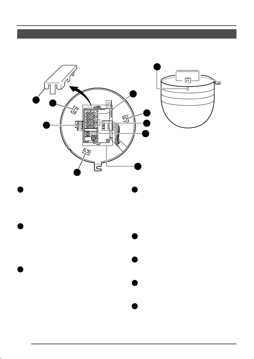
Body Underside
(Condition with terminal board attached.)
11
12
13
13
15
14
13
8
Terminal board
To connect the coaxial cable used as the
video signal cable, the power cable,
control signal cable, etc.
( See page 15)
9
Video output terminal
Outputs composite video signals (1 V
(p-p), output impedance 75Ω).
Should be connected to video input
terminal on monitor, switcher, or remote
control unit.
10
Control signal connection terminals
Terminals for inputting signals with
electrical characteristics conforming to
the EIA/TIA RS-422A or RS-485 standard.
Connected to the optional Remote
Control Unit RM-P2580, etc.
10
9
8
11
DC 12 V / AC 24 V input terminals
To input DC 12 V or AC 24 V power.
The AC 24 V power supply should
conform to the following:
U-type: Class 2 only
E-type: Isolated power supply only
12
Terminal board cover
Protects the cable connection terminals
from dirt, etc.
13
Camera body mounting guides (× 3)
To be inserted into the guide holes of the
ceiling mount.
14
Drop prevention wire hook
Attach the drop prevention wire to this
hook.
15
Camera positioning alignment mark
When mounting the camera onto the
ceiling mount, align this mark with the
mark on the mount.
10
Page 11
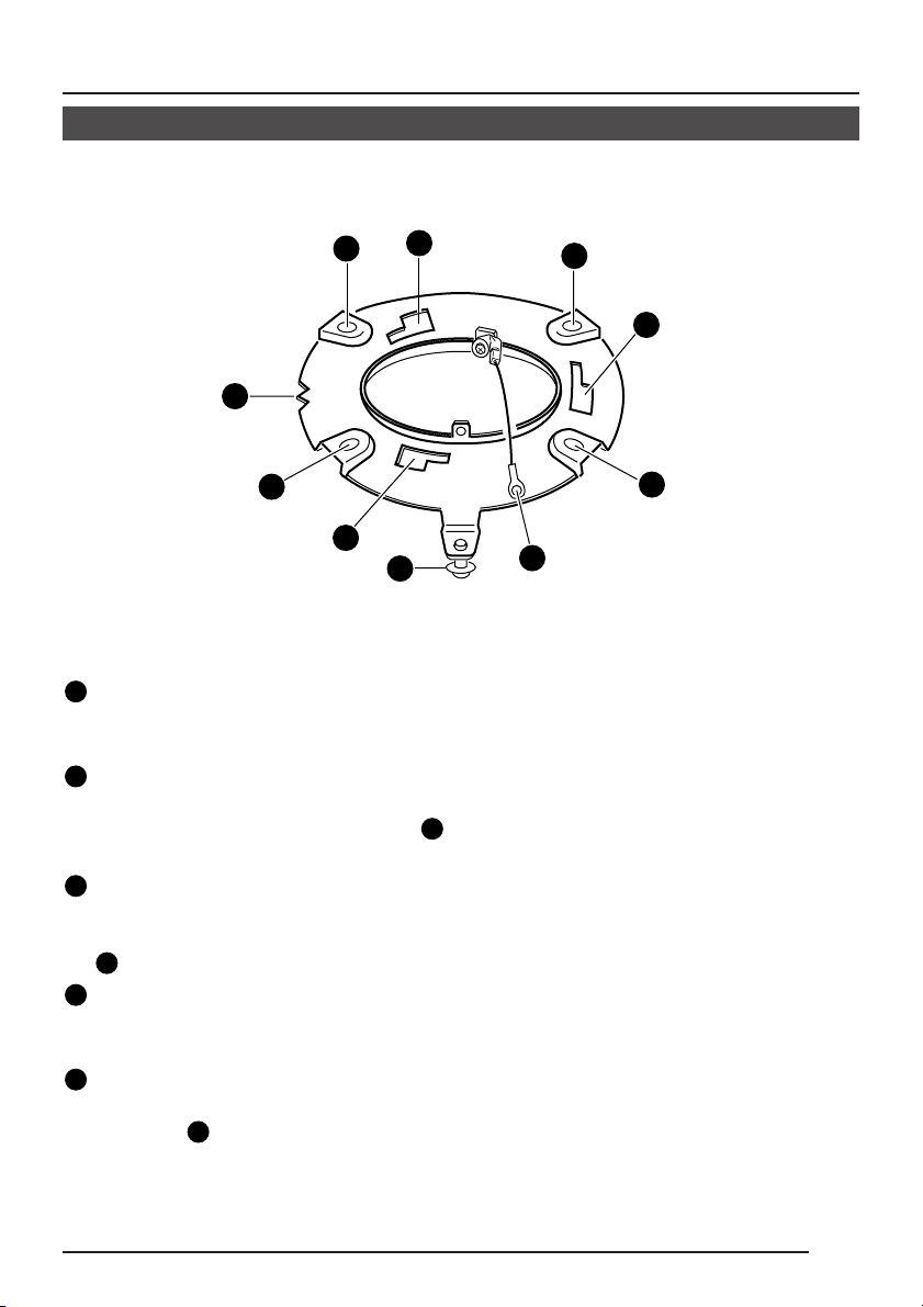
Ceiling Mount
16
19
16
17
16
Mounting holes (× 4)
Use these holes to attach the ceiling
mount to the ceiling.
17
Guide holes for mounting camera (× 3)
Guide holes for mounting the camera.
The camera body mounting guides
are inserted into these holes.
Camera clamping screw
18
To hold the camera in place, be sure to
use this screw to lock the camera clamp
4
.
Camera positioning alignment mark
19
Positioning mark for when the camera
body is attached.
20
Drop prevention wire hook
Attach this wire to the drop prevention
wire hook 14 on the camera body.
18
17
16
17
16
20
13
11
Page 12
TO CAMERA
DATA I / O
RX
RX
COM
COM
9/1
10/2
11/3
12/4
13/5
14/6
15/7
16/8
COM
COM
COM
CAMERA
SW
UNIT
ALARM
AUTO
MONITOR
OUTPUT
MONITOR
SERIAL-2
SERIAL-1
VIDEO INPUT
VIDEO OUTPUT
OUTPUT
ON
POWER
OFF
ON
AC INPUT
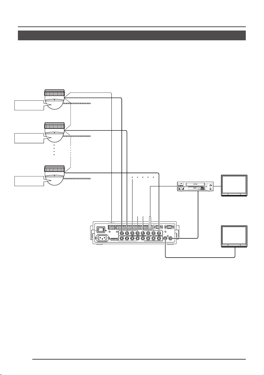
SYSTEM
System with Remote Control Unit RM-P2580
System with up to 8 cameras. (Six position settings available for each camera.)
COLOR DOME CAMERA
TK-C553
CAMERA 1
CAMERA ID:01
TERMINATION:OFF
COLOR DOME CAMERA
TK-C553
CAMERA 2
CAMERA ID:02
TERMINATION:OFF
COLOR DOME CAMERA
TK-C553
CAMERA 8
CAMERA ID:08
TERMINATION:ON
Remote Control Unit
Control signal cable
Video signal cable
Power cable
AC24V
AC24V
AC24V
CAMERA
RM-P2580
Time lapse VCR
MONITOR
CAM SW
OUT
DATA I / O
1 2 3 4 5 6 7 8
COM
9/1
10/2
11/3
1
2 3 4 5 6 7
1
2 3 4 5 6 7
CAMERA
SW
UNIT
12/4
13/5
14/6
15/7
16/8
COM
ALARM
AUTO
VIDEO INPUT
VIDEO OUTPUT
COM
CAMERA
SERIAL-1
COM
COM
SW
8
MONITOR
OUTPUT
8
TO
TO CAMERA
+
-
+RX
RX
−TX++TX-−
COM
〜
4312 875 6
ON
SERIAL-2
MONITOR
OUTPUT
1
2
MONITOR
OUTPUT 1
REC
STOP/EJECT
REC
CHECK
PAUSE/
STILL
PLAY
REVERSE
FFREW
MONITOR
OUTPUT 2
VIDEO CASSETTE RECORDER
COUNT/
SHIFT/TRACKING
RESET
MENU
CLOCK
/CANCEL
SET/V.LOCK
TIME
TIMER
AL/PL
MODE
REC
RESET
VIDEO IN
SR-L910E
OPERATE
OPE. LOCK
PAL
MONITOR
12
Page 13
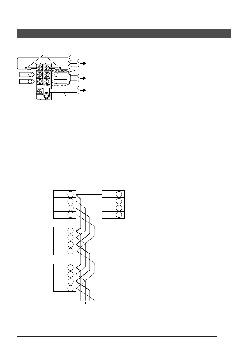
Lug plates
RX+ C
RX– D
Terminal board
DC 12 V or AC 24 V
power cable
A TX+
B TX–
Video
signal cable
To DC 12 V or AC 24 V power supply
Control signal cable
To Remote Control Unit (RM-P2580)
To Remote Control Unit (RM-P2580)
• Turn OFF the power supply to all equipment to be used before making connections.
• Read the Instruction Manual for each piece of equipment to be used before making
connections.
• The control signal cable cannot be used for loop connection.
Connecting the control signal cable
(Use a twisted-pair cable for connection. See page 16.)
Camera 1 terminal board
TX+ A
TX– B
RX+ C
RX– D
Camera 2 terminal board
TX+ A
TX– B
RX+ C
RX– D
Camera 3 terminal board
TX+ A
TX– B
RX+ C
RX– D
RM-P2580
RX+ A
RX– B
TX+ C
TX– D
Connect:
Camera TX+ to RM-P2580 RX+
Camera TX– to RM-P2580 RX–
Camera RX+ to RM-P2580 TX+
Camera RX– to RM-P2580 TX–
The A B C D marks indicated on both the camera
terminals and the RM-P2580 terminals facilitate correct
connections. Connect the terminals with identical
marks.
13
Page 14

PROT OOL:DUPLEXID-05C
MONITOR screen
SYSTEM
System with Remote Control Unit RM-P2580
Settings
CAMERA FACE
MONITOR
NOT USED
NOT USED
L/L
INT
OFF
ON
TERMINATION
LOCK
AWC
LEFT RIGHT
SET
UP
DOWN
• Video synchronization selector switch
(INT/LL)
Set to LL (Line Lock) on all cameras, and
align V.PHASE.
( See page 29.)
• Control signal termination ON/OFF switch
(TERMINATION OFF/ON)
Set this to ON only on the camera placed
at the end of the control signal cable.
Set to OFF on all other cameras.
Menu Screen Settings
COMMUNICATION menu screen
• MODE item: Set to DUPLEX
• STYLE item: Set to MULTIDROP
• ID item: Set the camera ID.
For each camera, match the ID with the
VIDEO INPUT number of the RMP2580.
* Settings on the COMMUNICATION
menu screen are performed using the
operation buttons on the front section
of the camera.
MEMO
Following selection of MEMORY, the settings
on the COMMUNICATION menu will not be
valid before the power has been turned on
again.
FUNCTION menu screen
Screen for making settings related to the
Auto Patrol and Auto Pan functions and
display of text.
14
INT
OFF
TERMINATION
• Settings on the FUNCTION menu are
performed using the operation buttons
on the RM-P2580. They cannot be
made using the operation buttons on
the camera body.
• Make settings on other menus as
required.
LL
ON
MEMO
When operating a system using the RMP2580, several cameras (up to 16) can be
connected and used on one control signal
cable. Consequently, an incorrect switch
setting on just a single camera will cause
the entire system to work incorrectly.
• Confirm switch settings on the screen
as follows.
q Confirm that the image from the camera
to be checked is displayed on the monitor.
w Turn OFF and then ON the power to the
camera to be checked.
e When the STYLE item is MULTIDROP,
characters similar to those shown in the
figure below are displayed for about 5
seconds. They do not appear in the case
of POINT to POINT.
r Confirm that “DUPLEX” and “ID-MM” are
displayed and that the ID number is the
correct number (the number should be the
same as the number of the VIDEO INPUT
terminal to which the camera is connected
on the rear panel of the RM-P2580).
t If wrong, set the MODE item, STYLE item
and camera ID again.
Monitor screen (example showing camera ID as “05”)
“DUPLEX” should be
displayed.
The number shown in
the MM part of IDMMshould be correct.
Page 15

INSTALLATION
Connections to Camera Terminal Board
• Turn OFF the power supply to all components before making connections.
Lug plates
RX+ C
RX– D
Terminal board
Remove the terminal board
cover by flipping it up while
pushing its top to the left.
DC 12 V or AC 24 V
power cable
To DC 12 V or AC
24 V power supply
A TX+
B TX–
Video
signal cable
Control signal cable
To Remote Control
Unit (RM-P2580)
To Remote Control Unit
(RM-P2580)
Connections to Terminal Board
Remove the terminal board cover and connect the video signal cable (coaxial cable)
(× 1).
Connect the DC 12 V or AC 24 V power cables
(× 2).
In a system where the Remote Control Unit
(RM-P2580), etc. is used, connect the control signal cables (× 4).
DC 12 V or AC 24 V power supply cable
Connect the DC 12 V or the AC 24 V power
supply to the DC 12V/AC 24V terminals on
the terminal board. To prevent connection
errors or a cable disconnection, we recommend the use of lug plates for the connections.
The following table shows the connection distances and connection cables provided that
2-conductor VVF cables (vinyl-insulated vinyl sheath cables) are used.
Maximum extension
(reference)
Conductor
diameter
100 m 260 m 410 m 500 m
1.0∅mm 1.6∅mm 2.0∅mm 2.6∅mm
and more and more and more and more
CAUTION:
• If thin cables are used (i.e. with a high
resistance), a significant voltage drop
will occur when the unit is at its
maximum power consumption. Either
use a thick cable to restrict the voltage
drop at the camera side to below 10%,
or place the power supply near to the
camera. If voltage drop occurs during
operation, the performance will be
unstable.
• Attach the cable conductors so that they
do not come into contact with the drop
prevention wires.
• Do not allow input from both a DC 12 V
and AC 24 V power supply at the same
time.
• When using a DC 12 V power supply,
ensure that the polarities of the cable are
correct.
• The AC 24 V power supply should conform to the following:
U-type: Class 2 only
E-type: Isolated power supply only
15
Page 16

INSTALLATION
Connections to Camera Terminal Board (Continued)
Video signal cables
Meshed wire
A TX+
B TX-
C RX+
D RX-
12mm
Fold the meshed wire back.
Polyethylene
Core
conductor
6mm
Connect to the
other side in
pairs like this.
Connect to the
other side in
pairs like this.
Connect the coaxial cables to the video
signal output terminals. Treat the tips of
the coaxial cables as shown on the left
before connection.
Note
Use the 3C-2V or 5C-2V video signal
cable (coaxial cable). The 7C-2V
cannot be used.
Control signal cables
These cables should be connected only
when it is required to control the camera using the RS-442A or RS-485 signals. The use of 0.65 4-conductor
twisted pair cables is recommended.
With these cables, the maximum extension distance is 1,200 m.
After having connected all of the required cables, again attach the terminal board cover.
Forgetting to attach the terminal board
cover could result in accidents or
injuries.
16
Page 17

Ceiling Installation
1.
φ75
Screws
2.
Ta b
Guide
3.
Ceiling mount
bracket
Screws
Ta b
Guide
Connector
Connector
cable
1.
Make a hole (75 mm diameter) in the
ceiling for passing the connection
cables, and attach the provided ceiling
mount to the ceiling.
Coincide the center of the mount with
the hole (75 mm diameter) for passing
the cables through the ceiling. Attach the
ceiling mount to the ceiling using 4
screws.
Pass the wired terminal board through
the hole in the center of the ceiling
mount and leave if hanging down.
• Use M4 screws or bolts for attaching
the ceiling mount.
• If wood screws are used, use screws
with a diameter of 4.1 mm.
• The screw head height should be no
more than 4 mm.
2.
Attach the wired terminal board to the
camera.
1) Slide the tab on the terminal board
into the guide on the camera. When
the terminal board is moved in the
direction of the arrow, it is secured to
the camera.
2) Connect the connector cable from
the camera body to the connector on
the terminal board.
3.
Attach the drop prevention wire.
As shown in the illustration, pull the drop
prevention wire out from the ceiling
mount and attach it to the drop prevention wire hook on the underside of the
camera body.
Drop prevention wire
Drop prevention
wire hook
CAUTION
Be sure to attach the drop prevention wire.
If not attached, the camera body could
drop down.
17
Page 18

INSTALLATION
Ceiling Installation (Continued)
4.
(2) Position alignment mark
(1)
Camera clamping
screw
(2)
(2) Camera position
alignment mark
Clamp
(3)
4.
Mount the camera body.
1) Ensure that the camera clamping
screw on the ceiling mount is
loosened.
2) Align the camera position alignment
mark on the camera body with the
camera position alignment mark on
the ceiling mount and press the
camera body straight against the
mount.
Note
Exercise caution when mounting so as not
to pinch the drop prevention wire and the
connected cables.
3) Rotate the camera body clockwise as
far as it will go.
At this point, check that the camera
body clamp is located on the lock
screw on the ceiling mount.
4) Tighten the camera clamping screw.
CAUTION
Rotate the
camera body
clockwise
18
Camera
clamping screw
Camera
clamping screw
(4)
Tighten the camera
clamping screw.
Be sure to tighten the camera clamping
screw fully. Otherwise the camera body
may vibrate or drop from the ceiling.
To dismount the camera from the ceiling,
perform steps
2.
to 4. in reverse order.
Page 19

Adjusting the Camera Angle
Camera head
MONITOR
NOT USED
NOT USED
L/L
INT
ON
OFF
UP
AWC
LEFT RIGHT
DOWN
TERMINATION
SET
LOCK
Horizontal LOCK
screw
Dome
cover
Remove the dome cover.
Rotate the dome cover counterclockwise and
pull it off.
Horizontal rotation
(adjustable range: 90°)
1.
Loosen the horizontal LOCK screw.
2.
Holding the both tilt lock screws, rotate
horizontally.
3.
Tighten the horizontal LOCK screw.
Vertical rotation
(adjustable range: 130°)
1.
Loosen the tilt lock screws.
2.
Holding the rotation levers, rotate
vertically.
3.
Tighten the tilt lock screws.
Image inclination
(adjustable range: 30°)
Manipulate the rotation levers to adjust the
inclination of the image.
Rotation levers
Tilt lock screws
Zoom ring
Focus ring
Adjusting the image size
Adjust the size using the zoom ring.
Adjusting the focus
Adjust using the focus ring.
When required, the surveillance image
should be adjusted, etc. This adjustment
is performed using the setup screen.
19
Page 20

INSTALLATION
Adjusting the Camera Angle (Continued)
2.2.
1.
Triangle mark
Notch
Attach the dome cover.
1.
Align the notch in the dome cover with
the triangle mark and push the cover
onto the camera body.
2.
Rotate the cover clockwise as far as it
will go and is seated firmly.
CAUTION
Be sure that the dome cover is firmly attached. Improper attachment could result
in the cover dropping down.
20
Page 21
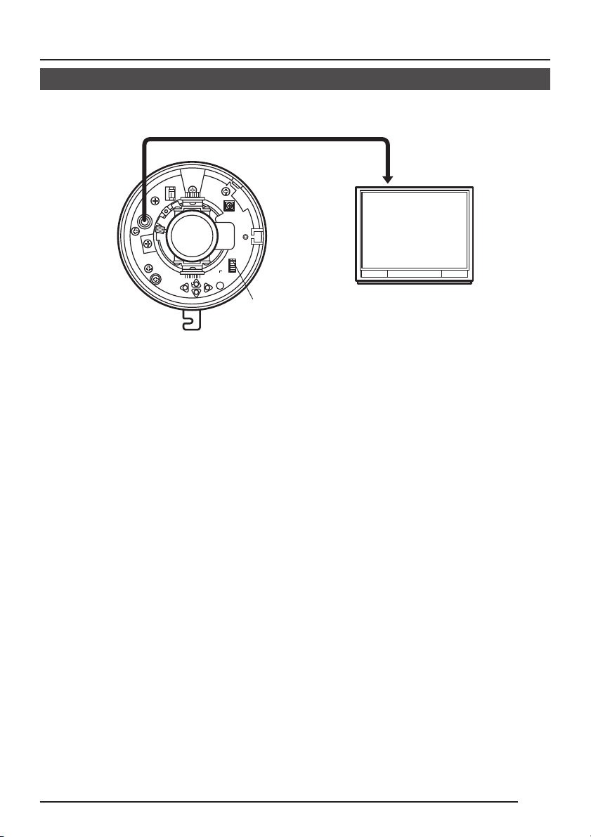
Connection for Adjustment of the Camera
Temporarily used for making various adjustments
while the camera remains in the installed location.
MONITOR
terminal
MONITOR
NOT USED
NOT USED
L/L
INT
ON
OFF
UP
AWC
LEFT RIGHT
DOWN
TERMINATION
SET
LOCK
DIP switch
* The power to the camera body must be ON when adjustments are performed.
75Ω termination
disconnected
Monitor TV
21
Page 22

SETUP MENU
SETUP MENU Flow
This unit is provided with a SETUP MENU that allows various settings to be performed on
the screen of a connected monitor using the switches on the camera body. The SETUP
MENU consists of separate layers divided according to function types as shown below.
The setup menus that can be set vary depending on whether the settings are done using the
operation buttons on the camera body or by transmitting commands from an external control
device, such as the JVC RM-P2580.
* Menu setting operation can only be conducted after the operation to display the SETUP
MENU has been performed (using the operation buttons on the camera body or by transmitted commands). ( See page 24, 25.)
SETUP MENU flow when the operation buttons on the camera body are used
See page 26. See page 27.
–– ETUP MENU––S
VI DE ADJUST . .O
MODE SE L EC T . .
COMM N IC AT I ON . .U
END MEMORY
SETUPMENUSCREEN VIDEOADJUSTSCREEN
–– IDEO ADJUST––V
I R I S LEV E L NORMA L
COLO LEVE LRU
ENHA CE L EVELN
AGC ODE 2 0 d BM
SUPE AGC OFFR
BLC. OFF.
AVER GE : PEAK 8 : 2A
WH I T B AL AN C E A TWE
END
NORMA L
NORMA L
(for setting functions related
to the video image of each
camera)
See page 29.
BLC PRESET AREA
screen
BLC AREA EDIT screen
AWC screen
MANUAL WHITE
BALANCE
adjustment screen
Normal screen
MEMO
The FUNCTION screen is not displayed
when operating the SETUP MENU using
the buttons on the camera body.
(for setting the form of connection to the control signal connection terminals
22
on the camera body, etc. and for setting the communication mode, etc.)
–– OD E SE L EC T ––M
CAME A TEX T OF FR
V.PH SE 128A
AUTO STAR T . . OF F
END
MODESELECTSCREEN
(for setting the operation mode
of each camera)
See page 30.
––CO MUNICATION––M
MODE
STYLE
ID 1
END
PO I NT t o PO I NT
DUPL E X
COMMUNICATIONSCREEN
CAMERA TEXT
setting screen
AUTO START DEMO
screen
Page 23

SETUP MENU Flow (Continued)
SETUP MENU flow when commands are transmitted from the RM-P2580
ETUP
S
POS I I ON SET UPT
CAME A . .R
CONT O L UN I T . .R
SETUP menu from remote
control
–– ETUP MENU––S
VI DE ADJUST . .O
MODE S EL EC T . .
FUNC I ON . .T
END MEMORY
SETUPMENUSCREEN VIDEOADJUSTSCREEN
Normal screen
..
Select the “CAMERA” item.
See page 26. See page 27.
–– IDEO ADJUST––V
I R I S L EV E L NORMA L
COLOU LEVELR
ENHA CE L EVELN
AGC ODE 2 0 d BM
SUPE AGC OFFR
BLC. OFF.
AVER GE : PEAK 8 : 2A
WH I T B AL AN C E A TWE
END
(for setting functions related
to the video image of each
camera)
See page 29.
–– OD E SE L EC T ––M
CAME A TEX T OF FR
V.PH SE 128A
AUTO STAR T . . OF F
END
NORMA L
NORMA L
BLC PRESET AREA
screen
BLC AREA EDIT screen
AWC screen
MANUAL WHITE
BALANCE
adjustment screen
CAMERA TEXT
setting screen
AUTO START DEMO
screen
MEMO
The COMMUNICATION screen is not
displayed when the SETUP MENU is set
by means of transmitted commands.
MODESELECTSCREEN
(for setting the operation mode
of each camera)
See page 31.
– FUNC T I ON–––
POS I I ON TEX T ED I T . .T
POS . EX T LOC . UP – LT
AUTO PATROL . .
AUTO PAN MOD E PAN
AL M . EX T S I Z E DOUB L ET
END
FUNCTIONSCREEN
(for settings related to POSITION
TEXT, AUTO PATROL, AUTO PAN
operation, etc.)
POSITION TEXT
setting screen
AUTO PATROL setting
screen
23
Page 24

–– ETUP MENU––S
VIDE ADJUST. .O
MODE S E LEC T . .
COMM N I CA T ION . .U
END MEMORY
SETUP MENU screen
SETUP MENU
Menu Settings Using the Operation Buttons on the Camera Body
MONITOR
LEFT button
1.
Press the SET button to display the
SETUP MENU screen on the monitor.
2.
Press the UP or DOWN button to align
the cursor (>) with the item to be set.
Then press the SET button.
• The submenu for the selected item
appears.
MEMO
Items followed by “..” are items that
have a submenu.
3.
Press the UP or DOWN button to align
the cursor (>) with the item to be set.
4.
Press the LEFT or RIGHT button to
change the set value.
When the set value of an item is
changed, the change mark (9) appears
after the cursor (>).
When items followed by the “..”
indication are selected, press the SET
button.
* The selected item’s setting screen
appears.
5.
To exit the submenu, press the DOWN
button to align the cursor (>) with END.
Then press the SET button.
• The SETUP MENU screen returns.
To set other submenus, repeat steps
2.
to
5.
6.
To complete the menu settings, align the
cursor (>) with the END item on the
SETUP MENU and press the LEFT or
RIGHT button to select the way to end
the setting.
To save the setting contents, be sure
to select “MEMORY”.
Finally, press the SET button.
* “DATA SAVED” is displayed in the
lower part of the screen, and then the
normal screen returns.
24
NOT USED
NOT USED
L/L
INT
ON
OFF
AWC
UP
LEFT RIGHT
DOWN
TERMINATION
SET
LOCK
DOWN button
Cursor
UP button
SET button
RIGHT button
VIDE ADJUST. .O
MODE S E LEC T . .
COMM N I CA T ION . .U
END MEMORY
SETUP MENU screen
Change mark
IRIS LEVEL NORMAL
COLOU LEVELR
ENHA CE LEVE LN
AGC ODE 2 0 d BM
SUPE AGC OF FR
BLC. OFF.
AVER GE : PEAK 8 : 2A
WH I T BALANCE ATWE
END
VIDEO ADJUST screen
Submenu to be followed
–– ETUP MENU––S
Item
–– I DEO ADJUST––V
Set value
NORMA L
NORMA L
Page 25

Menu Settings Using the RM-P2580
IRIS
AF
FOCUS
ZOOM
CLEAR
/HOME
AUTO
PAN
OPTION
OPTION
CAMERA
POSITION
AUTO
PATROL
WIDE
AUTO
PAN/TILT
LENS
CAMERA/POSITION
CAMERA
POSITION
REMOTE CONTROL UNIT
RM-P2580
MENU
button
SETUP
MENU SET
POS I I ON SE TU PT
CAME A . .R
CONT OL UN I T . .R
ETUP
S
..
Select the
CAMERA
item.
SET button
CAMERA
POWER
ALARM
KEY LOCK
REMOTE CONTROL UNIT
AUTO
RM-P2580
F-1 F-2 F-3
POSITION
SETUP screen from remote control
SET button
When using the RM-P2580.
FUNCTION
1.
Press the MENU button for about 3 seconds to display the remote control’s SETUP
screen on the monitor. (Above figure)
2.
Press the PAN/TILT control lever up (6) or down (7) to align the cursor (>) with the
CAMERA item. Then press the SET button.
• The SETUP screen appears. (See figures on the left.)
3.
Press the PAN/TILT control lever up (6) or down (7) to align the cursor (>) with the item
to be set. Then press the SET button.
• The selected itemís submenu appears.
MEMO
Items followed by “..” are items that have a submenu.
4.
Press the PAN/TILT control lever up (6) or down (7) to align the cursor (>) with the item
to be set.
5.
Press the PAN/TILT control lever to the left (8) or to the right (t) to change the set value.
When the set value of an item is changed, the change mark (9) appears after the cursor
(>).
When items followed by the “..” indication are selected, press the SET button.
* The selected item’s setting screen appears.
6.
To exit the submenu, press the PAN/TILT control lever down (7) to align the cursor (>)
with END. Then press the SET button.
• The SETUP MENU screen returns.
To set other submenus, repeat steps
7.
There are two methods to complete the menu settings.
• Align the cursor (>) with the END item on the SETUP MENU and press the PAN/TILT
control lever to the left (8) or to the right (t) to select the way to end. Finally, press
the SET button.
• Press the MENU button while the SETUP MENU screen is displayed. In this case, the
menu setting is completed in accordance with the setting displayed for the END item.
● To save the setting contents, be sure to select “MEMORY”.
•“DATA SAVED” is displayed in the lower part of the screen and then the normal screen
returns.
3.
to
CLOSE
NEAR
WIDE
6.
LENS
SPEED
IRIS
FOCUS
ZOOM
AF
OPEN
FAR
TELE CLEAR
CAMERA/POSITION
CAMERA
3
1
2
OPTION
OPTION
6
4
5
1
AUTO
8
9
7
PAN
PATROL
0
ENTER
/HOME
RM-P2580
PAN/TILT
POSITION
2
AUTO
PAN/TILT
control lever
25
Page 26

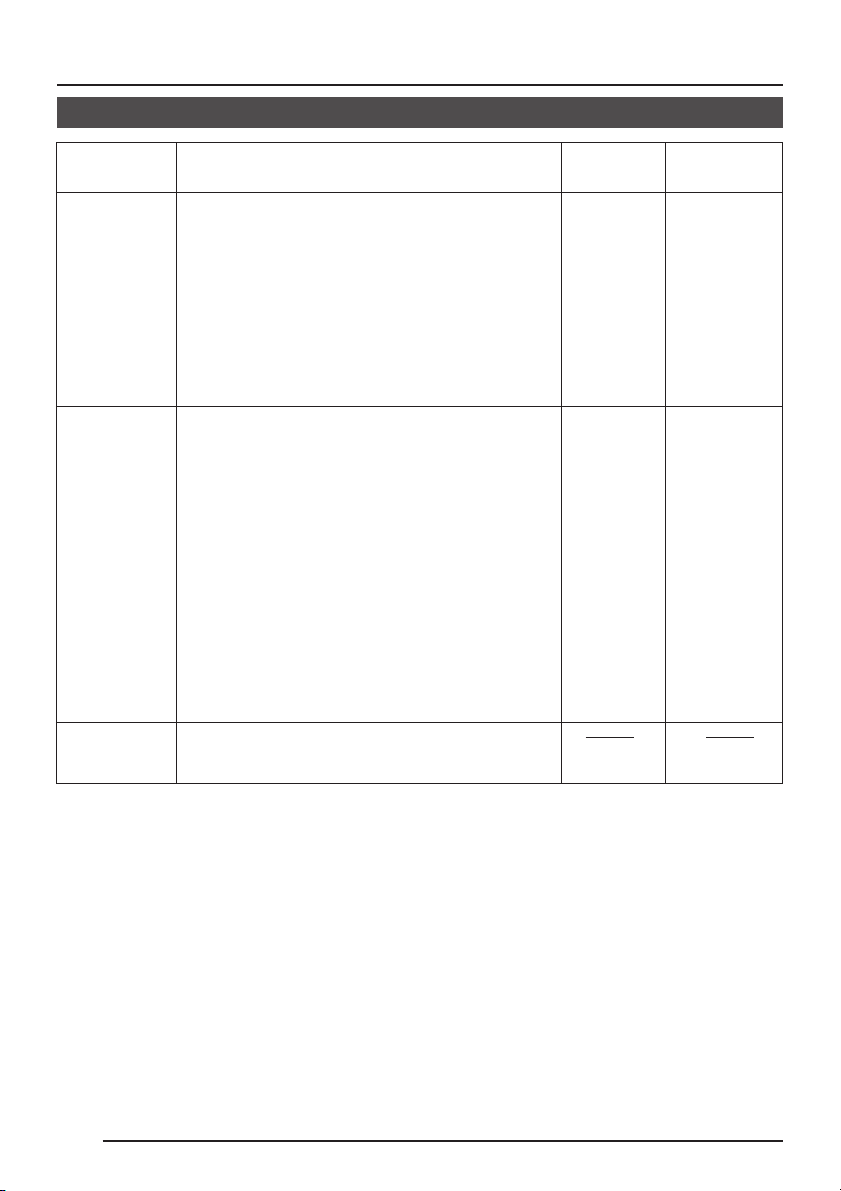
SETUP MENU
SETUP MENU Screen
Item Function
VIDEO
ADJUST
MODE
SELECT
COMMUNICATION
FUNCTION
END
Displays the VIDEO ADJUST. For adjusting functions related to the video image of
each camera.
Displays the MODE SELECT. For setting
the operation mode, etc. of each camera.
Only valid when settings are made using
the operation buttons on the camera body.
Displays the COMMUNICATION. For setting the form of connection to the control
signal connection terminals on the camera body and setting the communication
mode, etc.
Only valid when settings are made by
transmitting commands. Displays the
FUNCTION menu. For settings related to
POSITION TEXT, AUTO PATROL, AUTO
PAN, etc.
Closes the SETUP MENU screen so that
the normal screen returns. After selecting
this item, select the way to end the menu
setting.
MEMORY: Set contents are retained in
memory.
CLEAR: Settings of the following items
return to the contents valid before the setting, and other settings return to the factory settings.
• MANUAL WHITE BALANCE
• AWC
• CAMERA TEXT
• COMMUNICATION menu
FACTORY: Set contents return to the fac-
tory settings.
However, when making settings by means of transmitted
commands, the contents of the
COMMUNICATION menu do
not return to the factory settings.
Variable Factory
range setting
MEMORY
CLEAR
FACTORY
MEMORY
26
Page 27

VIDEO ADJUST Screen
Item Function
IRIS LEVEL
COLOUR
LEVEL
ENHANCE
LEVEL
AGC MODE
SUPER
AGC
BLC
Adjusts the brightness level of the video signal.
• To lower the brightness level …Decrease the
• To raise the brightness level … Increase the
To adjust the color level of the video signal.
• To make colors lighter … Decrease the value
• To make colors darker … Increase the value
To adjust the contour enhancing level of the
video signal.
• To make the picture quality softer …
Decrease the value
• To make the picture quality harder …
Increase the value
Sets the maximum gain of the AGC (Automatic
Gain Control).
• Set to OFF when the AGC function is not
used.
• Set to 20 dB when illumination is particularly
dim.
Used when the brightness is still insufficient
even if the AGC MODE is set at 20 dB.
ON: Gain level is increased.
OFF: Gain level is not increased.
* When SUPER AGC is ON;
• Dark areas of the screen may appear grainy.
• Gain will be set according to the setting of
the SUPER AGC with no relation to the AGC
MODE setting.
Sets the backlight compensation function. Set
when a bright light source, etc. is placed in the
same direction as the subject.
• OFF: The backlight compensation function
does not work.
• AREA 1 to AREA 4: When the SET button is
pressed, the fixed light metering areas are
displayed. Select one of the four types.
• EDIT 1 to EDIT 2: When the SET button is
pressed, the user light metering areas are
displayed. Select one of the two types.
See “BLC Adjustment” on page 32.
value
value
Variable Factory
range setting
–5 to
NORMAL
to 5
–5 to
NORMAL
to 5
–5 to
NORMAL
to 5
OFF
10 dB
20 dB
ON
OFF
OFF
AREA 1
AREA 2
AREA 3
AREA 4
EDIT 1
EDIT 2
NORMAL
NORMAL
NORMAL
20 dB
OFF
OFF
27
Page 28
SETUP MENU
VIDEO ADJUST Screen (Continued)
Item Function
AVERAGE:
PEAK
WHITE
BALANCE
END
Sets the exposure detection as a ratio of the
average value and the peak value.
• AVERAGE value large: Increase the AVERAGE value when portions other than the highlighted areas of the screen are dark and look
corrupted. (Ex. 10:0)
• PEAK value large: Increase the PEAK value
when halation occurs in the highlighted areas of the screen. (Ex. 5:5)
Selects the white balance adjustment function.
The white balance can be adjusted manually
or automatically for light within the color temperature range of 2500K to 8000K.
• ATW: Automatic color temperature ad-
justment mode.
• MANUAL:Manual adjustment mode. When
the SET button is pressed, the
adjustment screen appears.
See page 35.
• AWC: One-push auto white balance
mode. When the SET button is
pressed, the AWC operation
screen appears. See page 35.
When the SET button is pressed, the SETUP
MENU screen returns.
Variable Factory
range setting
10:0
9:1
8:2
7:3
6:4
5:5
ATW
MANUAL
AWC
8:2
ATW
28
Page 29

MODE SELECT Screen
Item Function
CAMERA
TEXT
V PHASE
AUTO
START
END
To select whether or not camera text is displayed and to display the CAMERA TEXT setting screen.
OFF: Camera text is not displayed.
ON: Camera text is displayed in the lower part
of the screen.
EDIT: When the SET button is pressed, the
CAMERA TEXT setting screen is dis-
played.
See page 36.
* When EDIT is selected and the SET button
is not pressed, and the cursor is moved or
you switch to another menu, this function is
automatically set to ON.
To adjust and align the vertical phase of the
camera body with other cameras operating in
the Line Lock (L/L) mode.
Adjust while viewing the monitor screen.
* Adjustment is made with the LEFT button and
RIGHT button or by pressing the PAN/TILT
control lever to the left or right.
To select the digital zoom operation mode for
when the power is turned on.
OFF: The digital zoom does not operate.
PAN/TILT/SCROLL/PATROL: When the SET
button is pressed, zoom operation takes place
in accordance with the set contents.
See page 38.
MEMO
This item does not function when operating
with the RM-P2580.
When the SET button is pressed, the SETUP
MENU screen returns.
Variable Factory
range setting
OFF
ON
EDIT
0 to 255
OFF
PAN
TILT
SCROLL
PATROL
OFF
128
OFF
29
Page 30

SETUP MENU
COMMUNICATION Screen
Only displayed when settings are made using the operation buttons on the camera body.
Item Function
MODE
STYLE
ID
END
Sets the communication form used for communication with the external control device,
such as the remote control unit.
SIMPLEX: Only reception of signals from the
external control device takes place.
DUPLEX: Signals are both sent to and received
from the external control device.
Set in accordance with the way the connection to the external control device, such as the
remote control unit, is made.
• POINT TO POINT: Select this setting when
the external control device is used to control
one single camera.
• MULTIDROP: Select this setting when the
external control device is used to control multiple cameras.
For setting the camera ID.
Be sure to set the camera ID when
MULTIDROP is selected for the STYLE item.
* Be careful not to duplicate the camera ID.
When the SET button is pressed, the SETUP
MENU screen returns.
Variable Factory
range setting
SYMPLEX
DUPLEX
POINT TO
POINT
MULTI-
DROP
1 to 99
DUPLEX
POINT TO
POINT
1
30
Page 31

FUNCTION Screen
Only displayed when making settings by sending commands from an external controller,
such as the RM-P2580.
Item Function
POSITION
TEXT EDIT
When the SET button is pressed, the POSITION TEXT setting screen is displayed. Up to
16 characters can be used as titles for set positions and home positions.
See page 39.
Variable Factory
range setting
POSI. TEXT
LOC.
AUTO
PATROL
AUTO PAN
MODE
ALM. TEXT
SIZE
Selects the position for displaying POSITION
TEXT on the screen.
UP-L: Upper left side DOWN-L: Lower left side
UP-C: Upper center DOWN -C: Lower center
UP-R: Upper right side DOWN-R: Lower right side
Used to set the position order and the surveillance time for Auto Patrol operation.
When the SET button is pressed, the AUTO PATROL setting screen appears.
See page 41.
Selects the operation mode when the AUTO
PAN command is received. (In the case of RMP2580, this selects the operation mode when
the AUTO PAN button is pressed.)
Set the size of the characters displayed in the
case of alarms.
ALARM
NORMAL DOUBLE
ALARM
UP-L
DOWN-L
UP-C
DOWN-C
UP-R
DOWN-R
PAN
TILT
SCROLL
NORMAL
DOUBLE
UP-L
PAN
DOUBLE
END
When the SET button is pressed, the SETUP
MENU screen returns.
31
Page 32

SETUP MENU
MENU
/HOME
AUTO
PAN
CAMERA
AUTO
PATROL
CLOSE
WIDE
F-1
F-3
CAMERA/POSITION
CAMERA
POSITION
REMOTE CONTROL UNIT
RM-P2580
BLC (Back Light Compensation) Adjustment
MENU
button
MONITOR
LEFT button
NOT USED
UP button
NOT USED
L/L
INT
ON
OFF
TERMINATION
LOCK
UP
AWC
LEFT RIGHT
DOWN
SET
SET button
RIGHT button
DOWN button
LOCK screw
Set when a bright light source is placed behind or in the direction of the subject making the
point difficult to view on the screen.
Make the setting after selecting the BLC item on the VIDEO ADJUST screen.
MEMO
BLC does not function while the digital zoom is in used.
Fixed Light Metering Areas
MENU
CLOSE
NEAR
WIDE
SETUP
SPEED
IRIS
FOCUS
ZOOM
SET
AF
OPEN
FAR
TELE CLEAR
SET button
CAMERA
POPOWER
ALARM
KEY LOCK
CAMERA/POSITION
1
2
4
5
8
7
0
/HOME
RM-P2580
REMOTE CONTROL UNIT
POSITION
CAMERA
3
OPTION
6
1
AUTO
9
PAN
ENTER
RM-P2580
AUTO F-1
F-2 F-3
PAN/TILTLENS
POSITION
OPTION
2
AUTO
PATROL
PAN/TILT
control lever
Light
metering
area
Light
metering
area
Light
metering
area
Light
metering
area
OFF AREA 1 AREA 2 AREA 3 AREA 4
32
Light
metering
area
Set the BLC item to any of AREA 1 to AREA
4. When the SET button is pressed, the
fixed light metering area is displayed on the
monitor.
Adjust so that the unwanted light source is
outside the light metering area.
To stop display of the light metering area:
• Press the SET button when operating on
the camera body.
• Press the MENU button when using RMP2580.
The VIDEO ADJUST screen returns.
Page 33

User Settable Light Metering Areas
SETUP
MENU
SET
SPEED
IRIS
FOCUS
ZOOM
OPEN
FAR
TELE
CLEAR
/HOME
ENTER
AUTO
PAN
OPTION
OPTION
CAMERA
POSITION
AUTO
PATROL
CLOSE
NEAR
WIDE
AUTO
F-1
F-2
F-3
PAN/TILT
LENS
CAMERA/POSITION
CAMERA
POSITION
REMOTE CONTROL UNIT
ALARM
WER
KEY LOCK
Select EDIT 1 or EDIT 2 for the BLC item.
When the SET button is pressed, the user
settable light metering area is displayed on
the monitor.
EDIT 1 EDIT 2
Light
metering
area
Light
metering
area
When operating using the RM-P2580
When operating using the camera body
1.
Use the LEFT or RIGHT button to shift
the position of the left side of the light
metering area, and use the UP or
DOWN button to shift the upper side.
2.
Press the SET button to change the
position to be set from the left/up side
to the right/down side.
Manual Adjustment of White Balance
MONITOR
NOT USED
NOT USED
L/L
INT
ON
OFF
AWC
LEFT RIGHT
TERMINATION
SET
UP
DOWN
LOCK
LEFT button
UP button
DOWN button
SET button
RIGHT button
3.
Use the LEFT or RIGHT button to shift
the position of the right side of the light
metering area, and use the UP or
DOWN button to shift the down side.
4.
When the SET button is pressed, the
VIDEO ADJUST screen returns.
1.
Press the SET button to select the light
metering area position to be set. (Left/
up ➝ right/down ➝ left/up ...)
2.
Press the PAN/TILT control lever to the
left (8) or to the right (t) to shift the
position of the left or right side,
respectively.
Press the PAN/TILT control lever upward
(6) or downward (7) to shift the up or
down side position.
3.
When the MENU button is pressed, the
VIDEO ADJUST screen returns.
MENU
button
MENU
CLOSE
NEAR
WIDE
SETUP
SET
LENS
SPEED
IRIS
FOCUS
AF
ZOOM
SET button
CAMERA
POPOWER
ALARM
KEY LOCK
1
OPEN
4
FAR
7
TELE
CLEAR
POSITION
CAMERA/POSITION
3
2
6
5
8
9
0
ENTER
/HOME
REMOTE CONTROL UNIT
RM-P2580
AUTO
F-1
F-2
F-3
PAN/TILT
CAMERA
POSITION
OPTION
OPTION
1
2
AUTO
AUTO
PAN
PATROL
PAN/TILT
control lever
RM-P2580
–– I DEO ADJUST––V
IRIS LEVEL NORMAL
COLO LEVELRU
ENHA CE L EVE LN
AGC ODE 2 0 d BM
SUPE AGC OF FR
BLC. OFF.
AVER GE : PEAK 8 : 2A
WH I T BALANCE UALMANE
END
VIDEO ADJUST screen
NORMA L
NORMA L
When automatic adjustment of the white balance results in a “reddish screen”, etc., adjust the white balance manually.
1.
Adjust the white balance manually.
Set the WHITE BALANCE item on the
VIDEO ADJUST screen to MANUAL
and press the SET button.
• The MANUAL WHITE BALANCE
adjustment screen appears on the
monitor.
33
Page 34

SETUP MENU
Manual Adjustment of White Balance (Continued)
2.
Select the hue to be adjusted. (R/B or
––MANU L WH I TE BALANC E ––A
:R -- ------------
-- ------------
g:
M
END
WHITE BALANCE
adjustment screen
––MANU L WH I TE BALANC E ––A
:R -- -----------
+
-- ------------
g:
M
END
Setting indicating mark
---:B
+
-
--:G
+
---:B
-
--:G
+
Original position
Mg/G)
When operating using the camera
body, press the UP or DOWN button.
When using the RM-P2580, press the
PAN/TILT control lever upward (6) or
downward (7).
3.
Adjust the hue.
When operating using the camera
body, press the LEFT or RIGHT
button.
When using the RM-P2580, press the
PAN/TILT control lever to the left (8)
or to the right (t).
• The “+” indicator moves in accordance
with the setting. When a setting is
changed, the “9” mark appears at the
original position.
4.
Concluding manual white balance
adjustment.
When operating using the camera
body, press the UP or DOWN button
to align the cursor (>) with the END
item. Then press the SET button.
When using the RM-P2580, press the
MENU button or use the PAN/TILT
control lever to align the cursor (>) with
the END item and then press the SET
button.
• The VIDEO ADJUST screen returns.
34
CAUTION:
The color temperature will be slightly affected when the dome cover is attached.
Pay attention to this when adjusting the
white balance manually.
Page 35

AWC (One-push Auto White Balance) Adjustment
Using a simple operation, the AWC function
allows the white balance to be fixed as the
MONITOR
LEFT button
UP(AWC) button
NOT USED
NOT USED
L/L
INT
ON
OFF
TERMINATION
LOCK
AWC
UP
LEFT RIGHT
DOWN
SET
AWC
RIGHT
DOWN
–– I DEO ADJUST––V
IRIS LEVEL NORMAL
COLOU L EVELR
ENHA CE L EVELN
AGC ODE 2 0 d BM
SUPE AGC OF FR
BLC. OFF.
AVER GE : PEAK 8 : 2A
WH I T BALANCE AWCE
END
NORMA L
NORMA L
VIDEO ADJUST screen
AWC OPERAT I ON
During AWC operation
AWC OK
AWC
Indication when operation is completed normally.
AWC NG: OBJECT
Indication in case of abnormality
one valid at a given point. Used for observation when the color temperature changes frequently.
1.
The following two methods are available
for activating the AWS function.
1
Press the UP (AWC) button on the
camera body for about 1 second
while the normal screen (no setup
menu shown) is displayed.
or
2
Set the WHITE BALANCE item on
the VIDEO ADJUST screen to AWC
and press the SET button. (Possible
both on the camera body and the
RM-P2580).
2.
When the AWC function is activated,
“AWC OPERATION” is displayed at the
bottom of the monitor screen.
3.
The result of the AWC operation is
displayed on the monitor screen for
approximately 5 seconds. Then the
screen displayed before the AWC
function was activated returns. (Normal
screen or VIDEO ADJUST screen)
Operation result indication
AWC OK : Completed
AWC NG : OBJECT : The color
AWC ERROR : HIGH LIGHT : Excessive
AWC ERROR: LOW LIGHT : Insufficient
Blinks
MEMO:
The AWC function invoked by the UP
(AWC) button on the camera body starts
up regardless of the setting of the WHITE
BALANCE item on the VIDEO ADJUST
screen.
normally
temperature is
outside the
tracking range
brightness
brightness
35
Page 36

SETUP MENU
SETUP
MENU
SET
SPEED
AF
OPEN
FAR
TELE
CLEAR
/HOME
ENTER
AUTO
PAN
OPTION
OPTION
CAMERA
POSITION
AUTO
PATROL
CLOSE
NEAR
WIDE
AUTO
F-1
F-2
F-3
PAN/TILT
LENS
CAMERA/POSITION
CAMERA
POSITION
REMOTE CONTROL UNIT
RM-P2580
ALARM
WER
KEY LOCK
CAMERA TEXT Setting
MONITOR
NOT USED
NOT USED
L/L
INT
ON
OFF
AWC
LEFT RIGHT
TERMINATION
SET
UP
DOWN
LOCK
LEFT button
UP button
DOWN button
SET button
RIGHT button
MENU
button
SETUP
MENU
SET
LENS
SPEED
IRIS
CLOSE
FOCUS
NEAR
AF
WIDE
ZOOM
ZOOM(WIDE)
button
SET button
CAMERA
POSITION
POWER
ALARM
KEY LOCK
CAMERA/POSITION
3
1
2
OPEN
6
4
5
FAR
8
9
7
0
TELE
CLEAR
ENTER
/HOME
ZOOM(TELE) button
REMOTE CONTROL UNIT
CAMERA
POSITION
OPTION
OPTION
1
2
AUTO
AUTO
PAN
PATROL
(RM-P2580)
RM-P2580
AUTO
F-1
F-2
F-3
PAN/TILT
PAN/TILT
control lever
Text input area
–– ODE SE L EC T ––M
CAME A TEX T TED IR
V.PH SE 128A
AUTO ST ART . . OFF
END
MODESELECTSCREEN
Space
–– AMERA TEXT––C
0 23456789 – :/.,1
AB DEFGH I JKLNMOPC
QR TUVWXYZS
ab de f gh i j k lmnopc
qr t uvwxyz’s
ÄÖ ÂÊ Î ÔÛÇÑЬ
длпцьвко фыбйну
аи м тщзсЯ ¡¿
SE ECT TEXT>ZOOML
CAMERA TEXT screen
Character area
ú
(Displayed only
for E-version)
Up to 24 characters can be selected as camera text for each camera. The set characters
are displayed at the bottom of the screen.
1.
Set the CAMERA TEXT item on the
MODE SELECT screen to EDIT. Then
press the SET button.
• The CAMERA TEXT screen appears
on the monitor screen.
• Characters selected from the
character area are displayed in the text
input area.
Setting using the camera body
2.
Use the UP or DOWN button to select
the position in the character input area.
The position moves to the right when the
UP button is pressed, and it moves to
the left when the DOWN button is
pressed.
3.
Use the LEFT or RIGHT button to select
the character to be input from the
character area.
4.
When the first character for the text has
been selected, press the UP button.
• The first character of the text is
confirmed, and the second character
can now be input.
36
Page 37

–– AMERA T E XT ––C
0 234 56789– :/.,1
AB DEFGH I JKL NMOPC
QR T U VWXY ZS
ab de fgh i j k lmnopc
qr t uvwxyz’s
ÄÖ ÂÊ Î ÔÛÇÑÜ
длп цьвко фыбй ну
аи мтщзсЯ ¡ ¿
SE ECT TEX T>ZOOML
CAMER
ú
(Displayed only
for E-version)
5.
When the whole text has been input,
press the SET button.
• The MODE SELECT screen returns.
Setting using the RM-P2580
2.
Use the ZOOM (TELE) or ZOOM
(WIDE) button to select the position in
the character input area. The position
moves to the right when the ZOOM
(TELE) button is pressed, and it moves
to the left when the ZOOM (WIDE)
button is pressed.
3.
Use the PAN/TILT control lever to select
the character to be input from the
character area.
4.
When the first character for the text has
been selected, press the ZOOM (TELE)
button.
• The first character of the text is
confirmed, and the second character
can now be input.
5.
When the whole text has been input,
press the MENU button.
• The MODE SELECT screen returns.
37
Page 38

AUTO SCROLE
SETUP MENU
AUTO START DEMO
–– ODE SE L E C T ––M
CAME A TEXT DEITR
V.PH SE 128A
AUTO S TART . . ROLPAT
END
MODE SELECT screen
AUTO S ART DEMONSTRAT I ONT
HOME
POSITION 5
AUTO PATROL (Factory setting)
( See page 41.)
MONITOR
NOT USED
NOT USED
L/L
INT
ON
OFF
TERMINATION
LOCK
AWC
LEFT RIGHT
SET
UP
DOWN
SET buttom
When the power is turned on, a demonstration of the zoom operation selected for the
AUTO START item on the MODE SELECT
screen takes place.
1.
Select the AUTO START item on the
MODE SELECT screen, and then press
the SET button.
• A zoom operation takes place in
accordance with the set contents
(PAN, TILT, SCROLL, PATROL).
At this point, “AUTO START
DEMONSTATION” is shown on the
monitor screen.
• In the case of PATROL, the position
change interval will be 10 seconds
regardless of the setting.
2.
POSITION 2POSITION 1
Stopping the DEMONSTRATION
operation
When using the camera body, press
the SET button.
When using the RM-P2580, press the
POSITION 4POSITION 3
MENU button.
• The MODE SELECT screen returns.
AUTO PAN
38
AUTO TILT
Page 39

POSITION TEXT Setting
SETUP
MENU
SET
SPEED
IRIS
FOCUS
ZOOM
OPEN
FAR
TELE
CLEAR
/HOME
ENTER
AUTO
PAN
OPTION
OPTION
CAMERA
POSITION
AUTO
PATROL
CLOSE
NEAR
WIDE
AUTO
F-1
F-2
F-3
PAN/TILT
CAMERA/POSITION
CAMERA
POSITION
RM-P2580
ALARM
WER
KEY LOCK
MENU
button
(RM-P2580)
ZOOM (TELE) button
ZOOM (WIDE) button
– FUNCT I ON–––
POSI ION TEXT EDIT..T
POS . EX T LOC . UP – LT
AUTO PATROL . .
AUTO PAN MODE PA N
ALM. EXT S I ZE DOUBLET
END
FUNCTION screen
Character area
Space
– PSITIONTEXT–O
POSITION TEXT screen
Text input area
0 23456789 – :/.,1
AB DEFGH I JKLNMOPC
QR TUVWXYZS
ab de f gh i j k lmnopc
qr t uvwxyz’s
ÄÖ ÂÊ Î ÔÛÇÑЬ
длпцьвко фыбйну
аи м тщзсЯ ¡¿
SE ECT TEX T>ZOOML
SETUP
MENU
SET
LENS
SPEED
IRIS
OPEN
CLOSE
FOCUS
FAR
NEAR
AF
TELE
WIDE
ZOOM
––
ú
(Displayed only
for E-version)
SET button
CAMERA
POPOWER
ALARM
KEY LOCK
CAMERA/POSITION
1
2
4
5
8
7
0
CLEAR
/HOME
ENTER button
Numeric key buttons
POSITION
REMOTE CONTROL UNIT
RM-P2580
AUTO
F-1
F-2
F-3
CAMERA button
POSITION button
POSI-
OPTION
PATROL
PAN/TILT
TION
2
AUTO
PAN/TILT control lever
CAMERA
3
OPTION
6
1
AUTO
9
PAN
ENTER
A title can be set for the registered positions
for each camera. The position title can only
be set by transmitting commands from the
RM-P2580, etc. The position title can consist
of up to 16 characters. The set characters are
displayed at the bottom of the screen.
Select the camera for which position
title text should be set and select the
position.
• Use the CAMERA button ➝ Numeric
key ➝ ENTER button to select the
camera.
• Use the POSITION button ➝ Numeric
key ➝ ENTER button to select the
position.
For details, see the instruction manual
for the RM-P2580.
1.
Align the cursor (>) with the POSITION
TEXT EDIT item on the FUNCTION
screen, and then press the SET button.
• The POSITION TEXT screen is
displayed on the monitor.
2.
Use the ZOOM (TELE) or ZOOM
(WIDE) button to select the position in
the character input area.
The position moves to the right when the
ZOOM (TELE) button is pressed, and it
moves to the left when the ZOOM
(WIDE) button is pressed.
39
Page 40

SETUP MENU
POSITION TEXT Setting (Continued)
3.
–– PSITIONTEXT––O
0 23456789 – :/.,1
AB DEFGH I JKLNMOPC
QR TUVWXYZS
ab de f gh i j k lmnopc
qr t uvwxyz’s
ÄÖ ÂÊ Î ÔÛÇÑЬ
длпцьвкофыбйну
аи м тщзсЯ ¡ ¿
SE ECT TEX T>ZOOML
OPSI
ú
4.
5.
6.
Use the PAN/TILT control lever to select
the character to be input from the
character area.
When the first character for the text has
been selected, press the ZOOM (TELE)
button.
• The first character of the text is
confirmed, and the second character
can now be input.
To set other position text titles, use the
POSITION button ➝ Numeric key ➝
ENTER button to change the position
2.
number. The repeat steps
to 4. to set
the text.
When setting of all titles is completed,
press the MENU button.
• The FUNCTION screen returns on the
monitor.
40
Page 41

AUTO PATROL Setting
SETUP
MENU
SET
SPEED
IRIS
AF
FOCUS
ZOOM
OPEN
FAR
TELE
CLEAR
/HOME
ENTER
AUTO
PAN
OPTION
OPTION
CAMERA
POSI-
TION
AUTO
PATROL
CLOSE
NEAR
WIDE
AUTO
F-1
F-2
F-3
PAN/TILT
LENS
CAMERA/POSITION
CAMERA
POSITION
REMOTE CONTROL UNIT
RM-P2580
ALARM
WER
KEY LOCK
HOME
MENU
button
SETUP
MENU
SET button
POPOWER
ALARM
SET
KEY LOCK
(RM-P2580)
REMOTE CONTROL UNIT
CAMERA
POSITION
RM-P2580
AUTO
F-1
F-2
F-3
POSITION
button
PAN/TILT
control lever
AU TO PAT ROL
button
POSITION 5
AUTO PATROL (Factory setting)
POSITION 2POSITION 1
LENS
SPEED
IRIS
CLOSE
FOCUS
NEAR
AF
WIDE
ZOOM
CAMERA/POSITION
CAMERA
3
1
2
OPEN
FAR
TELE
OPTION
6
4
5
8
9
7
0
CLEAR
ENTER
/HOME
PAN/TILT
POSITION
OPTION
1
2
AUTO
AUTO
PAN
PATROL
POSITION 4POSITION 3
The AUTO PATROL function allows you to
– FUNCT I ON–––
POSI ION TEXT EDIT..T
POS . EX T LOC . UP – LT
AUTO PATROL
AUTO PAN MODE PA N
..
ALM. EXT S I ZE DOUBLET
END
specify multiple positions (up to 6 positions)
that the camera will move to in the specified
order and observe for the specified interval.
The order of movement and observation interval for the AUTO PATROL operation can
only be set by transmitting commands from
the RM-P2580, etc.
1.
Align the cursor (>) with the AUTO
PATROL item on the FUNCTION
FUNCTION screen
screen. Then press the SET button.
• The AUTO PATROL setting screen
appears on the monitor.
The PATROL1 to 6 items indicate the
AUTO PATROL operation order.
PATROL1: Specifies the first position
number and the observation
…
interval for AUTO PATROL.
PATROL6: Specifies the last position
number and the observation
interval for AUTO PATROL.
2.
Press the PAN/TILT control lever up (6)
or down (7) to align the cursor (>) with
the PATROL No. item to be set.
41
Page 42

SETUP MENU
AUTO PATROL Setting (Continued)
3.
4.
5.
POSITION number
setting
HOME
POS1
to
POS5
Observation
time
10s
20s
30s
45s
1min
2min
SKIP
6.
To start the AUTO PATROL operation, press
the AUTO PATROL button on the RMP2580.
Press the POSITION button to set the
position number of the selected PATROL
No. item.
Press the PAN/TILT control lever to the
left (8) or to the right (t) to set the
observation interval for the selected
PATROL No.
• If set to SKIP, observation will not take
place at this position.
Repeat steps 2. to 4. to set the position
number and observation interval for all
the PATROL No. items.
When the AUTO PATROL setting is
completed, press the MENU button or
use the PAN/TILT control lever to align
the cursor (>) with the END item and
then press the SET button.
• The FUNCTION screen returns on the
monitor.
42
Page 43

SPECIFICATIONS
CAMERA
Signal system: U type based on NTSC
standard
E type based on PAL stan-
dard
Image device: 1/4” IT CCD
Effective picture elements:
U type 380,000 pixels,
768 (H) × 494 (V)
E type 440,000 pixels,
752 (H) × 582 (V)
Sync system: Line lock/Internal
Video S/N: 50 dB (AGC OFF)
Horizontal resolution:
470 TV lines (Typ.)
Minimum illumination:
4 l× (Full wide angle, AGC
20 dB, Y: 25%)
× (Full wide angle,
1.5 l
AGC 20 dB, Y: 25%, no
cover)
Camera ID: 24 letters
White balance: ATW/Manual/AWC
(one-push white balance)
Color temperature range
2500K to 8000K.
Backlight compensation:
Available by adjustment of
light metering area posi-
tion.
GENERAL
Remote control input:
RS-422A or RS-485
(non-isolated) connector
Baud rate: 9600 bit/s
Power requirement:
AC 24 V ` 50/60 Hz or
DC 12 V
Power consumption:
U type Approx. 3.6 W
E type Approx. 300 mA
Mass: 570 ˝ (including ceiling
mount)
Operating temperature:
–10°C to 50°C (recommended: 0°C to 40°C)
Dimensions: Approx. 112 mm diam-
eter × 113 mm
Accessories:
U type E type
• Instructions × 1 • Instructions × 2
• Ceiling mount × 1 • Ceiling mount × 1
• Terminal board × 1 • Terminal board × 1
• Warranty card × 1
• Service information
card × 1
External dimensions [Unit: mm]
φ112
φ110
LENS
Focal length: 2.6 mm to 6 mm (variable)
Max. aperture ratio:
F1.2 to F1.8
Angle of vision:
f = 2.6 mm
82° (H) × 59° (V)
f = 6 mm
35° (H) × 26° (V)
Angle adjustment range:
Horizontal: 90°
Vertical: 130°
Tilt: 30°
SR52
φ106
H=113
• Design and specifications are subject to
change without notice.
43
Page 44

TK-C553 COLOR DOME CAMERA
VICTOR COMPANY OF JAPAN, LIMITED
®
is a registered trademark owned by VICTOR COMPANY OF JAPAN, LTD.
®
is a registered trademark in Japan, the U.S.A., the U.K. and many other countries.
© 2000 VICTOR COMPANY OF JAPAN, LIMITED
Printed in Thailand
SC96896H-001
 Loading...