

Page 1

MNEU SETTING
Super LoLux
0.4
lux
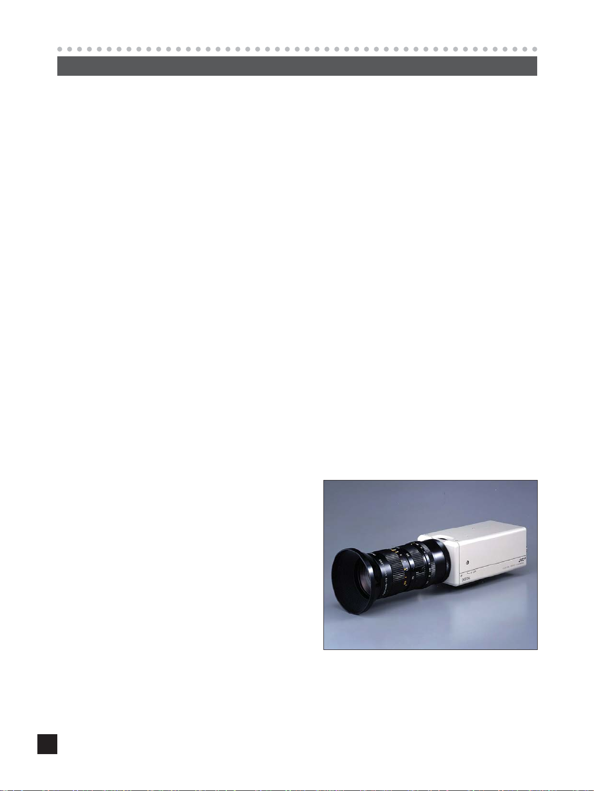
TK-C1480E
1/2" HIGH RESOLUTION COLOUR VIDEO CAMERA
Product Guide
1
Page 2
CONCEPT
New TK-C1480E series
When JVC introduced its TK-1280E series and TK-C1380E series to the 1/2" camera market,
they are widely accepted and recognized as standard-setting cameras.
The new TK-C1480E series, which is to maintain market leadership, adopts newly developed
DSP and CCDs, which feature much higher sensitivity, as well as more functions than its
predecessor, the TK-C1380E series. Added functions include: backlighting and remote
surveillance with RS-422A/RS-485 communications.
Features
Using the 1/2-inch EXVIEW CCD permits sensitivities of 0.8 lux (F 1.2, 50%) and 0.4 lux (F
1.2, 25%). When combined with the slow shutter function, these are increased to 0.025 lux (F
1.2, 50%) and 0.0125 lux (F 1.2, 25%), respectively.
Until now it has been difficult to clearly distinguish between bright and dark subjects in the
same view. With the introduction of JVC’s newly developed DSP this shortcoming no longer
exists, making 24-hour surveillance possible.
For remote camera parameter setting in repeat surveillance communication, RS-422A/
RS-485 standards are provided. An easy-to-use parameter setup menu and high-quality
shooting with no backlight, both of which are popular functions of the TK-C1380E, are also
adopted by the new series.
1/2" IT 440,000-Pixel CCD
Super LoLux
480 TV Lines
S/N 50dB
ExDr (Extended Dynamic Range function)
Motion Detection
RS-422A/RS-485 Communication
Auto Black ON/OFF
Slow Shutter for High Sensitivity
It’s Able to Control by RM-P2580
1
Page 3

DETAILED FEATURES
Super LoLux Sensitivity
TK-C1380E TK-C1480E
0.95 lux, 25% 0.4 lux, 25%
2.0 lux, 50% 0.8 lux, 50%
Spectral Response
TK-C1380E (Conventional CCD) TK-C1480E (EXVIEW CCD)
Using a new high-sensitivity CCD
permits Super LoLux photography.
0.025 lux (50% at slow shutter x32)
0.0125 lux (25% at slow shutter x32)
1.0
0.8
0.6
0.4
0.2
0.0
400 450 500 550 600 650 700
Cy
Ye
G
Mg
Wave Length (nm)
1.0
0.8
0.6
0.4
Relative Response
0.2
0.0
400 450 500 550 600 650 700
Cy
Ye
G
Wave Length (nm)
Mg
Because there is a difference in the spectral response of the CCD between TK-C1380E and TK-C1480E, the
same color reproduction is difficult to obtain. (Of course, we have tried to adjust the color matrix of the
TK-C1480E so that it is as close as possible to that of TK-C1380E.)
2
Page 4
DETAILED FEATURES
ExDr
ExDr mode: This is the shutter mode for a subject for which strong light and normal (or low) light conditions
coexist.
The ExDr mode is divided into two further modes:
Manual ExDr mode and Auto ExDr mode.
1 Manual ExDr mode:
Selectable high speed shutter
1/500 to 1/20,000
Other Competitors style: Fixed
Variable contrast level
+5 to -5
Minus (-) direction: The iris is set at strong light.
Plus (+) direction: The iris is set at low light.
Other Competitors style: Auto only
2 Auto ExDr mode:
The iris at the strong light portion and at the low light portion can be automatically detected and the results are
combined to determine the required shutter speed.
Variable contrast level
+5 to -5
Minus (-) direction: Adjusted for strong light
Plus (+) direction: Adjusted for low light
48 area
Auto peak detect → auto shutter
3
Page 5

JVC's positioning compared to competing companies
JVC TYPE (ExDr)
EXPANDABILITY SYSTEMS
CCD: SELECT ANY CHIP FROM MARKET
DSP & SOFTWARE: JVC EXCLUSIVE DSP & SOFTWARE
ANY CHIP FROM MARKET
e.g. able to use high
performance CCD like EXVIEW
OTHER MANUFACTURERS’ TYPE
CLOSED CIRCUIT SYSTEMS
CCD: EXCLUSIVE CCD
DSP & SOFTWARE: EXCLUSIVE DSP & SOFTWARE
EXCLUSIVE CCD
HYPER PROGRESSIVE
&
&
EXCLUSIVE JVC ORIGINAL
DSP AND SOFTWARE SYSTEMS
EXCLUSIVE DSP
AND SOFTWARE SYSTEMS
4
Page 6

DETAILED FEATURES
DIFFERENCE BETWEEN OTHER MANUFACTURER AND JVC TYPE FOR WIDE-DYNAMIC RANGE
HIGH LIGHT
SHUTTER
NORMAL LIHGT
SHUTTER
1. OTHER MANUFACTURER STYLE (PAL)
Normal Shutter Normal Shutter
For WIDE-Dynamic range function
CCD : EXCLUSIVE HYPER PROGESSIVE CCD
DSP : EXCLUSIVE PROCESSING
1/50
(FIX)
1/50
(FIX)
1/50
(FIX)
1/100
(FIX)
1/100
(FIX)
1/100
(FIX)
1/4000
(FIX)
1/4000
(FIX)
1/4000
(FIX)
2. JVC STYLE (PAL)
MERIT : better S/N level
DEMERIT : reduce the sensitity(reduce the graduation)
PAL long shutter : 1/100(FIX)
auto 1/10000
manual 1/20000
MANUAL ADJUST
POSSIBLE !!
MANUAL ADJUST
POSSIBLE !!
MANUAL ADJUST
POSSIBLE !!
x 2times reading x 2times reading x 2times reading
For WIDE-Dynamic range function
CCD : USE ANY CCD FROM MARKET(JVC USES EXVIEW)
DSP : EXCLUSIVE PROCESSING
1/50 1/50 1/501/50
MERIT : keep sensitivity(better graduation)
DEMERIT : AGC changeable based on the condition and if it has high light object,
it has noisy picture(S/N)
mixed picture output
under 1/60 shutter
with Gain control
mixed picture output
under 1/60 shutter
with Gain control
mixed picture output
under 1/60 shutter
with Gain control
A path B path
2 path reading
x2times reading
A path B path
2 path reading
x2times reading
A path B path
2 path reading
x2times reading
1/50 1/50 1/50 1/50
Variable
(Auto &
manual)
Variable
(Auto &
manual)
Variable
(Auto &
manual)
RAM
(MEMORY)
RAM
(MEMORY)
RAM
(MEMORY)
MIXED
PICTURE
OUTPUT
WITH 1/60
SHUTTER
MIXED
PICTURE
OUTPUT
WITH 1/60
SHUTTER
MIXED
PICTURE
OUTPUT
WITH 1/60
SHUTTER
MIXED
PICTURE
OUTPUT
WITH 1/60
SHUTTER
MIXED
PICTURE
OUTPUT
WITH 1/60
SHUTTER
MIXED
PICTURE
OUTPUT
WITH 1/60
SHUTTER
5
Page 7
High-speed side shutter operation for ExDr-AUTO
SHUTTER LENS
(Auto Iris Operation)
Sees the highest peak on
the divided-by-48 portion.
Adjusts (and sets) the
shutter so that the peak
value may become a
certain level.
Lowers the high-speed
side shutter speed
(down to 1/100 second)
If still too dark for a speed
of 1/100 second, then WD
is set to OFF (WD-AUTO).
And at a speed of 1/50
second AGC is turned ON.
Simultaneous operation
Automatic
Too bright
as a whole
Stops down
the lens
Too dark
as a whole
Opens
the lens
When the lens is fully
open because the area is
too dark as a whole.
(Note) Slow shutter mode is not available for WD-ON and manual operation.
Auto Exdr, Auto and Normal modes are available for Sense Up operation.
Manual Exdr and Manual modes are not available for Sense Up operation.
6
Page 8

DETAILED FEATURES
Contrast MIX method (or Contrast Mixing)
Low
brightness
side
(Long
Shutter)
High
brightness
side
(Short
Shutter)
Input
200%
100%
Input
200%
100%
Output
Output
MIX
200%
100%
Compression
Input
200%
100%
Compressed
to 1/2
Input
200%
Input
A
Output
+
Output
Level on the Menu shows the value of changing (A).
+5 565mV 80%
+4 540mV 77%
Contrast
level
adjust (or
adj.)
menu on
the Menu
+3 515mV 74%
+2 490mV 70%
+1 465mV 66%
normal 440mV 63%
-1 415mV 59%
-2 390mV 56%
-3 365mV 52%
-4 340mV 49%
-5 315mV 45%
*A place where low brightness is detected
100%
This is multiplied
by the gamma and
the knee.
Input
200%
100%
High
Low
Output
High
A
Low
Output
7
Page 9

Slow Shutter
Available (selectable) modes are: Off, x2, x4, x8, x16, x24 and x32. The same picture is stored in multiple fields
to obtain increased sensitivity.
In this case a decrease of resolution of 50% results when only even fields are used (odd fields are not used).
P.S. Priority Mode
The slow shutter speed can be used when AGC is ON.
1 Motion
AGC is turned ON first, followed by slow shutter-ON.
(Motion picture priority mode)
2 Picture
If AGC is turned ON first, noise tends to be introduced.
To prevent noise slow shutter is turned ON prior to turning AGC ON. If, however, the prime requirement is
sensitivity, AGC is turned ON first (with no consideration given to increased noise).
8
Page 10

DETAILED FEATURES
It is possible to set freely the area where MOTION DETECTING functions.
MOTION DETECT screen
flash
lights gray flash
Setting screen
1. Select the item AREA EDIT on
the MOTION DETECT screen.
2. Press the SET button.
The setting screen is brought up.
3. Select the area not subject to
detection using the
button.
The area flashing ON and OFF in black
and white moves.
4. Press the SET button.
The area not subject to detection is set,
and it turns gray (lights up).
To cancel the set area, press the SET
button again.
5. Repeat items 3 and 4 above.
6. Upon completion of setting,
press the MENU button.
The screen returns to the MOTION
DETECT menu.
MEMO
Indicated positions on the screen are rough
guides.
Be sure to check and conform the positions
on the actual screen.
* It is possible to check and confirm the set
areas on the DEMONSTRATION screen.
The detection area is shown in gray.
Motion Detect
TIMO ON DETECT
MO E OFFD
LE EL NORMALV
AR A ED I TE
ALRMTI EM10sA
DEONSTRA T I N
M
..
O
..
9
Page 11

Communication
Communication complies with RS-422A/RS-485 standards.
Setup menu is given below.
Main menu Communication menu
Be sure to make the necessary settings prior to connection.
MENU
SYNC ADJUST
ALC SET T I NGS
VIDEO ADJUST
MODE ESLECT
MOT ION
COMMUNI CAT I ON
FACTORY SETT I NGS
..
..
..
..
TECT
E
D
SYNC DAJUST
VPHASE 0
HPHASE 0
SC ECOARS 0
..
..
..
SC F I NE 12 8
WH T E BA L E ATWNC
I
CO OUR L E NORMALEL
L
EN ANCE LE NORMALEL
H
PEESTAL LE NORMALEL
D
AUOBLAC K OFFTL
T
MO E OFFD
LE EL NORMALV
AR A ED IE
ALRMTI EM10sA
DEONSTRA TIN
M
CTFA ORY SE NGSTTI
CA CELN
CL A W I(HOUT T I TLE )RTE
C
LA()RALLE
DEVI O ADJUST
A
V
V
V
C
TIMO ON DE TEC T
T..
O
LACSETTINGS
IIRSLEVEL NORMAL
AEVRAEG:PEAK 82:
SUTHTERExDR)(
ACGMODE
SNSEEUP OFF
PIORRITY –––
WH I TE BALANCE CONTROL
AWC SET . .
::
RB
g
::
MG
.
.
BCLOFF
CAMERA T I TL E E D I T. .
REVERS E MODE OFF
ALM .T I TLE S ZEIDOUBLE
ALARM COLOUR WH I TE
ST LE M.DROPY
MA H N E DII 1C
MODE SE LEC T
MMCO UNI CAT ION
NRMALO
2dB0
SHUT T RE(ExDR)
SHUTTER SPEED
FAST L IM IT
EDxER
LLEV
SPEED
EDxR
M.
CAMERA T
0123456789
ABCDE KL MNOPFGHI J
QRS T U VWXYZ
abcde klmnopf g hi j
qrstuvwxyz
ÄÖ ÂÊ Î Ô ÛÇÑ
Ü
äëï öüâê îô
¡¿
аим тщзсЯ
WIDE TELE
TDislayitle
ITL
’
ыбйну
1 120/
–––
–––
–––
:-/
E
.,
ú
DATA CLEARED
10
Page 12

Camera 2
control signal
connection terminals
Connect:
Camera TX+ to RM-P2580E RX+
Camera TX– to RM-P2580E RX–
Camera RX+ to RM-P2580E TX+
Camera RX– to RM-P2580E TX–
The A B C D marks indicated on both the
camera terminals and the RM-P2580E terminals facilitate correct connections. Connect
the terminals with identical marks.
Connecting the control signal cable
(Use a twisted-pair cable for connection. )
Camera 1
control signal
connection terminals
Setting the switches
Select the synchronization method of the
camera image.
Set the switch on all cameras to LL (Line Lock)
and match with the V. PHASE.
Set this switch to the DUPLEX
* If the setting is changed, be absolutely sure to
switch on the power again.
Set this switch to ON (signal termination ON)
only on the camera placed at the end of the
control signal cable.
Set to OFF on all other cameras.
Setting on the MENU screen
* If the setting is changed, escape from the menu screen once, and definitely switch on the power again.
MACHINE ID setting switches
Set this item to match the RM-P2580E VIDEO
INPUT terminal number for each camera.
When connecting
● Turn OFF the power supply to all equipment to be used before making connections.
● Carefully read the Instructions for each piece of equipment to be used before making
connections.
● For the appropriate connection cables and the length of these, carefully read “Connections on
the back” on page 16 of Instruction Manual.
● The control signal cable cannot be used for loop connection.
Set to M.DROP
Set to M.DROP when the RM-P2580E is used
as a remote control unit. When controlling from
another machine, make sure that it matches
the communication system used.
RM-P2580E
DETAILED FEATURES
Connect cables as shown below.
EXT TERM-OFF
SET
CAMERA
SETUP
EXT TERM-OFF
RX TERM-OFF
NOT USED
ST LE M.DROPY
MA H NE DII 1C
INT/GL
DUPLEX
ON
LL
SIMPLEX
ON
IRIS
VIDEO
DC
MMCO UN I CAT I ON
AWC
MENU
INT/GL
DUPLEX
RX TERM-OFF
NOT USED
ON
LL
SIMPLEX
ON
TX
TX
RX
RX
+ A
B
+ C
D
RM-P2580
A RX +
B RX
C TX
+
D TX
TX+ A
TX
RX
RX
B
+ C
D
11
Page 13

Auto Black
Using the Auto Black function the pedestal level can be controlled automatically when AGC is turned ON.
Auto Black Operation (or Control) (ON)
Changes the SET UP (default of pedestal) position in accordance with the AGC gain.
The SET UP position stays at +5 (100 mV approx.) for a PEDESTAL-on-the-MENU of +5 (Max.) irrespective of
the AGC, while it varies from -5 (0 mV) to +5 (100 mV) in accordance with the AGC gain for a PEDESTAL-onthe-MENU of -5.
Pedestal
Level
100mV
Pedestal = +5
50mV
Pedestal = 0
0mV
Pedestal = -5
0dB 10dB 20dB AGC Gain
The thick line indicates the default (set at factory)
Pedestal Setting (Pedestal = 0) + AGC ON (GAIN = 20dB).
12
Page 14

DETAILED FEATURES
White Balance Adjustment
Two white balance modes available to use by TK-C1480.
1. ATW - Automatice White Balance (Auto mode)
Always white balance traced depending on the colour temperature
2. AWC - Automatice White Balance control (one push mode)
It's able to have white balance each object scene. Also sometimes there might be not able to have white
balance with ATW. Such case, please use AWC.
After that, manual painting possible (2Axis) with set up by user.
WH I TE BALANCE CONTROL
AT W AWCor
WH I TE BALANCE CONTROL
AWC SE T. .
:
RB
g
:
MG
:
:
In addition, AWC is possible by pushing set button (apx.2sec) on the side switches of camera.
13
Page 15

COMPARISON
SPECIFICATION TK-C1380E TK-C1480E/1481EG
Image Sensor 1/2" 1/2" Super LoLux Type
Number of Pixels 752 (H) x 582 (V) 752 (H) x 582 (V)
Video S/N Ratio 48dB (AGC OFF) 50dB (50%, AGC OFF)
Minimum Illuminations 2.0 lux (50% F1.2 AGC ON) 0.8 lux (50% F1.2 AGC ON)
0.95 lux (25% F1.2 AGC ON) 0.4 lux (25% F1.2 AGC ON)
Sync Method Internal Internal
Line-Lock Line-Lock
Full Genlock Full Genlock
L.Lock Phase Adjust YES YES
H Phase Adjust YES YES
SC Phase Adjust YES YES
Horizontal Resolution 470 TV Lines 480 TV Lines
Video Output Composite video signal Composite video signal
Y/C Output YES YES
White Balance ATW ATW
MANUAL AWC (Paint possible)
AGC OFF/9dB/18dB/Super AGC OFF/10dB/20dB/Super AGC
BLC ON/OFF 6 patterns (2 edits) ON/OFF 6 patterns (2 edits)
AES 1/50 — 1/100,000 sec. 1/50 — 1/100,000 sec.
(ON/OFF switchable) (ON/OFF switchable)
Electronic Shutter 1/100, 1/250, 1/500, 1/1,000, 1/100, 1/250, 1/500, 1/1,000,
1/2,000, 1/4,000, 1/10,000 sec. 1/2,000, 1/4,000, 1/10,000 sec.
Camera ID 24 characters 24 characters
Set-Up Menu ENHANCE, IRIS, COLOUR, HUE, ENHANCE, IRIS, COLOUR,
PEDESTAL, Av:Pk Levels PEDESTAL, Av:Pk Levels
Wide Dynamic NO YES
Dynamic Range 200X (Max. at Auto)
400X (Max. at Manual)
Digital Zoom NO NO
Slow Shutter NO YES (Max.: X32)
IR ON/OFF NO NO
Communication NO YES (RS-422A/RS-485 by menu)
Lens Video iris (rear) Video iris (side 4-pin switch)
DC iris (side) DC iris (side 4-pin switch)
Lens Mount C/CS mount C/CS mount
Ambient Temperature -10°C to 50°C (operation) -10°C to 50°C (operation)
0C° to 40°C (recommend) 0C° to 40°C (recommend)
Ambient Humidity Less than 90% Less than 90%
Weight 640g 580g
Power Requirement DC12V/AC24V/AC230V DC12V/AC24V/AC230V (1481EG)
Dimensions (H x W x L) 67 x 70 x 148 mm 63 x 70 x 138 mm
14
Page 16

COMPARISON
COLOR VIDEO CAMERA
BF LOCK
DIGITAL
70
42
71
138
149
35
55
63
U1-32
1/4-20 UNC
41
70
55 1.5
148
159
Dimensions (Unit: mm)
TK-C1380E TK-C1480E
15
Page 17

CONTROLS, CONNECTORS AND INDICATORS
Lens Mount
This means to attach the lens.
This is applicable to both the C-mount lenses (1/2 inch)
and CS-mount lenses (1/2 inch).
Backfocus Adjustment Ring
Adjusting the back focus during lens installation.
When readjustment is required, loosen the locking
screw
by turning it counterclockwise and turn the
back focus adjustment ring
.
After the adjustment, tighten the locking screw
again.
The TK-C1480 has been adjusted to the optimum
position for the C-mount system before shipment.
[BF LOCK] Back Focus Locking Screw
This serves to fix the back focus-adjusting ring.
Camera-Mounting Bracket
The bracket has been attached on the bottom of the
camera before shipment. It can also be attached on
the top according to the circumstance.
To re-attach the bracket use the threaded holes at the
top, with the camera mounting brac ket locking screws
.
Camera-Mounting Screw Hole (1/4 inch)
Use this hole when mounting the camera
onto a fixer , pan/tilt unit, and the lik e . (Use a
screw shorter than 7 mm.)
Rotation-Preventive Hole
Make use of this rotation-preventive hole to prevent
any fall when mounting the camera. Make sure that
the camera is securely mounted.
Camera Mounting Bracket Fixing Screws (×2: M2.6
× 5 mm)
Do not use any screws longer than 5 mm.
TK-C1380E
1 Camera Mounting Holes (1/4-inch)
Use one of these threaded holes when mounting the
camera on a mount or turret. Two threaded holes are
provided on the front and rear and can be selected
according to the circumstance.
2 Camera Mounting Bracket Locking Screws (x3:
M2.6x5mm)
Do not use any screw longer than 5 mm.
3 Camera Mounting Bracket
The bracket has been attached on the bottom of the
cameras before shipment. It can also be attached on the
top according to the circumstance.
To re-attach the bracket use the threaded holes at the
top, with the 3 camera mounting bracket locking screw
2.
4 Backfocus Adjustment Ring
This ring both allows the adjustment of the backfocus to
and switch as the lens mounting method C and CS.
Loosen the BF LOCK screw 5 by turning it
counterclockwise before turning this ring, and be sure to
secure screw 5 by turning it clockwise after turning this
ring. The TK-C1380/TK-C1381 has been adjusted to the
optimum position for the C mount before shipment.
5 [BF LOCK] Backfocus Locking Screw
This screw locks the backfocus adjustment mechanism.
TK-C1480E
2
1
3
4
5
7
1
2
3
3
4
7
5
6
7
6
2
3
MAX.
7
mm
16
Page 18

CONTROLS, CONNECTORS AND INDICATORS
TK-C1380E TK-C1480E
6 Lens Mount
The lens mount is compatible with C-mount lenses (1/2
and 2/3 inches) and CS-mount lenses (1/2-inch).
7 [DC IRIS] DC Iris Connector
Connect to an auto-iris lens which does not incorporate
an EE amplifier.
These functions such as ! $ of TK-C1480E
are not available on TK-C1380E.
!@# $
SET
CAMERA
SETUP
MENU
AWC
EXT TERM-OFF
RX TERM-OFF
NOT USED
VIDEO
INT/GL
DUPLEX
DC
ON
LL
SIMPLEX
ON
IRIS
890
Cover
8
The cover opens if it is pulled to the left while being
pushed.
[VIDEO/DC] Iris Selector Switch
9
This is set according to the type of lens when an
automatic iris control lens is used.
VIDEO: In case of lens with EE amp built-in.
DC: In case of lens without EE amp built-in.
(VIDEO: At time of factory shipment)
[IRIS] Iris Terminal
10
This is connected to an automatic iris control lens.
[MENU] Menu Button
11
When the button is pressed, a menu screen is brought
up.
[SET/AWC] Set. Auto White Control Button
12
SET: Press this button to display a sub-menu.
AWC: If this button is kept pressed for more than 1
second, a one-push-auto-white-balance
function works and sets the white balance.
Once it is set, even if colour temperature
changes, white balance does not change. It is
also possible to make fine adjustments on the
set white balance.
[ , , , ] Up-and-Down, Left-and-Right Button
13
These buttons select items on the menu screen and
change a set value.
[EXT.TERM-ON/OFF] Terminal On/Off Switch of
14
External Synchronization Signal
This is a terminating ON/OFF switch for the external
synchronization input signal.
When this is switched ON, termination is executed via
a 75 Ω resistor.
ON: terminates at 75Ω.
OFF: does not terminate at 75Ω.
(ON: At time of factory shipment)
%
^
&
*
17
Page 19

TK-C1380E TK-C1480E
8 [SYNC IN] Sync Signal Input Connector
This BNC connector accepts the input of an external
sync signal such as a composite video (VBS) or black
burst (BB) signal. When a sync signal is input into this
connector, the camera operation is automatically
synchronized with the external sync signal.
The 75-ohm termination of this connector can be
switched on/off on the menu screen as required.
9 [VIDEO OUT] Video Signal Output Connector
This BNC connector outputs a composite video signal.
Connect this to the video input connector of a video
mounter, switcher, etc.
0 [POWER] Power Indicator Lamp
This lights when power is supplied to the camera.
.
[INT/GL, LL] Selector Switch for Synchronizing
15
System
This switch can set a synchronizing system of th e
camera.
INT/GL:
This is set for internal synchronization (INT) or external
synchronization (GL).
LL (Line Lock):
The camera’s vertical synchronization is locked to the
AC 24V power line frequency.
When switching between multiple cameras using a
switcher, selecting this mode and adjusting the vertical
phase can reduce the monitor sync disturbances
occurring when the camera image is switched. (This
cannot be used in regions where the power frequency is
50 Hz.) (INT/GL: At time of f actory shipment)
[DUPLEX, SIMPLEX] Selector Switch for
16
Transmission System
If the setting is changed, be absolutely sure to switch
on the power again.
DUPLEX:
This switch sets to DUPLEX when the transmission
between the camera and a remote control unit is in a
duplex system (two-way).
SIMPLEX:
This switch sets to SIMPLEX when the transmission
between the camera and a remote control unit is in a
simplex system (one-way).
(DUPLEX: At time of factory shipment)
[RX.TERM-ON/OFF] RX Signal Terminal ON/OFF
17
Switch
This sets whether or not the signal between RX + and
RX – on the back
of 110Ω resistance.
ON: terminates.
OFF: does not terminate.
If the system including the camera is the M.DROP
(Multi-drop, RS-485) system, only the camera mounted
at the terminal of control signal cable is set to “ON”
and the other camera is set to “OFF”. In case of the
M.DROP system, it becomes necessary to set the
Machine ID .
If the system including the camera is the P TOP (Point
to Point, RS-422A) system, set this switch of all the
cameras to “ON”.
The item STYLE on the COMMUNICA-TION screen
sets M.DROP or P TO P
(ON: At time of factory shipment)
NOT USED
18
This cannot be used. Do not switch.
should be terminated at the value
20
18
Page 20

CONTROLS, CONNECTORS AND INDICATORS
[DC 12V, AC 24V] Power Input Terminals
To input DC 12V or AC 24V power.
[TX+A, TX-B , RX+C , RX-D ] Control Signal
Connection Terminals
Terminals for inputting signals with electrical
characteristics conforming to the EIA/TIA RS-422A or
RS-485 standard.
RX.TERM switch
[AUX, GND] Auxiliary Output Terminals
If any change occurs in the area that was set on the
MOTION DETECT screen, these ter minals output
signals. Open collector output of a LOW pulse for
between 500 ms and 1,000 ms. Max voltage 30V,
current 30 mA.
[Y/C OUT] Y/C Output Connector
This 4-pin connector outputs the luminance and
chrominance signal.
• Pin configuration of Y/C OUT connector
[VIDEO OUT] Video Signal Output Connector
This BNC connector outputs a composite video signal.
Connect this to the video input connector of a video
monitor, switcher, etc.
[POWER] Power Indicator Lamp
This lamp lights when power is supplied to the camera.
[SYNC IN] Sync Signal Input Connector
This BNC connector accepts the input of an external
sync signal such as a composite video (VBS) or black
burst (BB) signal.
When a sync signal is input into this connector, the
camera operation is automatically synchronized with
the external sync signal.
To terminate this connector at 75Ω, turn ON the
EXT.TERM switch
.
Pin No. Signal
1 GND
2 GND
3 Luminance (Y, 1 V(p-p), 75Ω)
4 Chrominance (C, 0.3 V(p-p), 75Ω)
TK-C1380E TK-C1480E
! [Y/C OUT] Y/C Output Connector
This 4-pin connector outputs the luminance and
chrominance signal.
Pin configuration of Y/C OUT connector
@ [CAMERA SET UP] Camera Set-up Screen
Operation buttons
These buttons are used in the set-up operations.
# [VIDEO IRIS] Video Iris Connector
Connect to an auto-iris lens incorporating an EE
amplifier.
$ [DC12V/AC24V] Power Input Connector
(TK-C1380E only)
Connect a DC 12 V±10% or AC 24 v±10%, 50/60 Hz
power supply.
% Power Cable (for TK-C1381EG only)
Connect to the commercial AC 230V outlet
19
20
21
22
t
r
AC24
DC12
C IEIDE
1 2
)(
CA 2 ( E)
IAED E
(E E)
ABCD
/C
q
GD
A
w
EE I
CI
MA A
e
17
4
2
3
1
19
23
24
25
14
Page 21

SPECIAL SETTINGS BY JVC SERVICE CENTER
Special Settings by JVC Service Center
It is able to have the following settings by JVC service center absolutely.
1. CCD SPOT Compensation
It is possible to compensate the CCD spot up to 3 blemish under ExDr off mode.
2. Level of Auto ExDr
Normally it is not able to change the shutter speed for Auto ExDr mode. However, it is able to have
a little change from default under small tolerance.
For further information, please call to JVC service center.
20
Page 22

MINI SYSTEM
1
TO CAMERATO CAMERA DATA I / ODATA I / O
RXRX+RXRX-TXTX+TXTX
-
COMCOM
1 2 3 4 5 6 7 8
COMCOM
9/1 10/2 11/3 12/4 13/5 14/615/7 16/8
COMCOM COMCOM COMCOM
CAMERACAMERA
SW
UNITUNIT
ALARMALARM
AUTOAUTO
431 2 875 6
2 3 4 5 6 7
8
1
MONITORMONITOR
OUTPUTOUTPUT
MONITORMONITOR
SERIAL-2SERIAL-1
VIDEO INPUTVIDEO INPUT
VIDEO OUTPUTVIDEO OUTPUT
OUTPUTOUTPUT
2
1
ONON
2 3 4 5 6 7
8
POWER
OFF
ON
AC INPUT
CAM SW
PARALLEL ALARM
UP TO 16 POSITIONS
VIDEO
IN
VIDEO
IN
VIDEO
VIDEO
TO
CAMERA
VCR
SPOT
RM-P2580
RS-485
CAMERA 1
CAMERA 8
Camera 4
monitor
MONITOR
ALARM UNIT
REC
REC
STOP
REC
CHECK
EJECT
OPERATE
OPERATE
SPOT
Sample Sample
Camera 1
monitor
DIP SW 1 “OFF” (A mode)
Setting Multi-drop
Hold
SETUP
POSITION SETUP..
CAMERA..
CONTROL UNIT..
DIP SWITCH
4312 8756
ON
RX
-
TX
-
TX
+
RX
+
CAMERA MENU
COLOR VIDEO CAMERA
B
F
L
O
C
K
DIGITAL
COLOR VIDEO CAMERA
B
F
L
O
C
K
DIGITAL
ID:01
ID:08
MMCO UN I CAT I ON
ST LE M.DROPY
MA H NE DII 1C
21
Page 23

MINI SYSTEM
1
TO CAMERA DATA I / O
RXRX+RXRX-TXTX+TXTX
-
COMCOM
1 2 3 4 5 6 7 8
COMCOM
9/1 10/211/3 12/4 13/514/6 15/716/8
COMCOM COMCOM COMCOM
CAMERACAMERA
SW
UNITUNIT
ALARMALARM
AUTOAUTO
431 2 8756
2 3 4 5 6 7
8
1
MONITORMONITOR
OUTPUTOUTPUT
MONITORMONITOR
SERIAL-2SERIAL-1SERIAL-1
VIDEO INPUTVIDEO INPUT
VIDEO OUTPUTVIDEO OUTPUT
OUTPUTOUTPUT
2
1
ONON
2 3 4 5 6 7
8
POWER
OFF
ON
AC INPUT
CAM SW
VIDEO
VIDEO
RS-485
RM-P2580
SW-D7000
CAMERA 1
CAMERA 2
CAMERA 3
REC
REC
STOP
REC
CHECK
EJECT
OPERATE
OPERATE
REC
REC
STOP
REC
CHECK
EJECT
OPERATE
OPERATE
VCR
VCR
MONITOR
FIXED CAMERAS
ALARM
UNIT
IN
IN
MONITOR OUT
231
564
897
CASCADE
MONITOR
8 cameras x 64 positions
PARALLEL ALARM IN
PARALLEL ALARM OUT
(Up to 8 positions)
CAMERA
MENU
DISPLAYED
DIP SW 1 “OFF” (A mode)
DIP SWITCH
4312 8756
ON
Setting Multi-drop
Hold
RX-TX
-
TX
+
RX
+
RS-485
SETUP
POSITION SETUP..
CAMERA..
CONTROL UNIT..
CAMERA MENU
SampleSample
PARALLEL ALARM UNIT
COLOR VIDEO CAMERA
B
F
L
O
C
K
DIGITAL
COLOR VIDEO CAMERA
B
F
L
O
C
K
DIGITAL
COLOR VIDEO CAMERA
B
F
L
O
C
K
DIGITAL
ID:01
ID:02
ID:03
MMCO UN I CAT I ON
ST LE M.DROPY
MA H NE DII 1C
22
Page 24

REMOTE CONTROL SOFTWARE
JVC Remote Control Software
Remote control software (RS422A type) is available by JVC as a purpose of demonstration at free.(The
performance is not guaranteed by JVC due to demonstration purpose. Also not able to open source code.)
The following is GUI image
Option Dialog
Menu
Features
1. Camera control possible by RS422A interface
2. Video image output available on the GUI using video card or it is able to connect from camera to video
monitor with BNC.
Connections
1. Remote control ------ Please prepare locally converter from RS422A to RS232C.
After execute JVC software,please have right click and select options settings. Kindly check COM port
setting.
The below is just example.
CAM Converter PC
RS422A RS232C RS232C
TX+ ----------RX+
TX------------RX- TX------------RX
RX+ ----------TX+ RX -----------TX
RX- ----------TX- GND ---------GND
Refer to Converter, please kindly check with instruction manual of conveter because depending on the
converter, the connection between PC and converter is different.
2. Video card ------ Please arrange locally video card(PCI bus or PCMCIA type) and install the driver into PC.
After execute JVC software, please have right click and select options settings. Then kindly select driver in
capture device.
Camera Controls
By GUI of this software, it's able to set up ExDr/shutter, Iris/BLC, AGC/SENS UP (slow shutter), Auto EXP, white
balance, video adjustment,reverse image, camera ID. However, it is not possible full set up. So to have full set
up, please use camera menu in GUI and select&set parameters by cursol.
23
Page 25

 Loading...