

Page 1
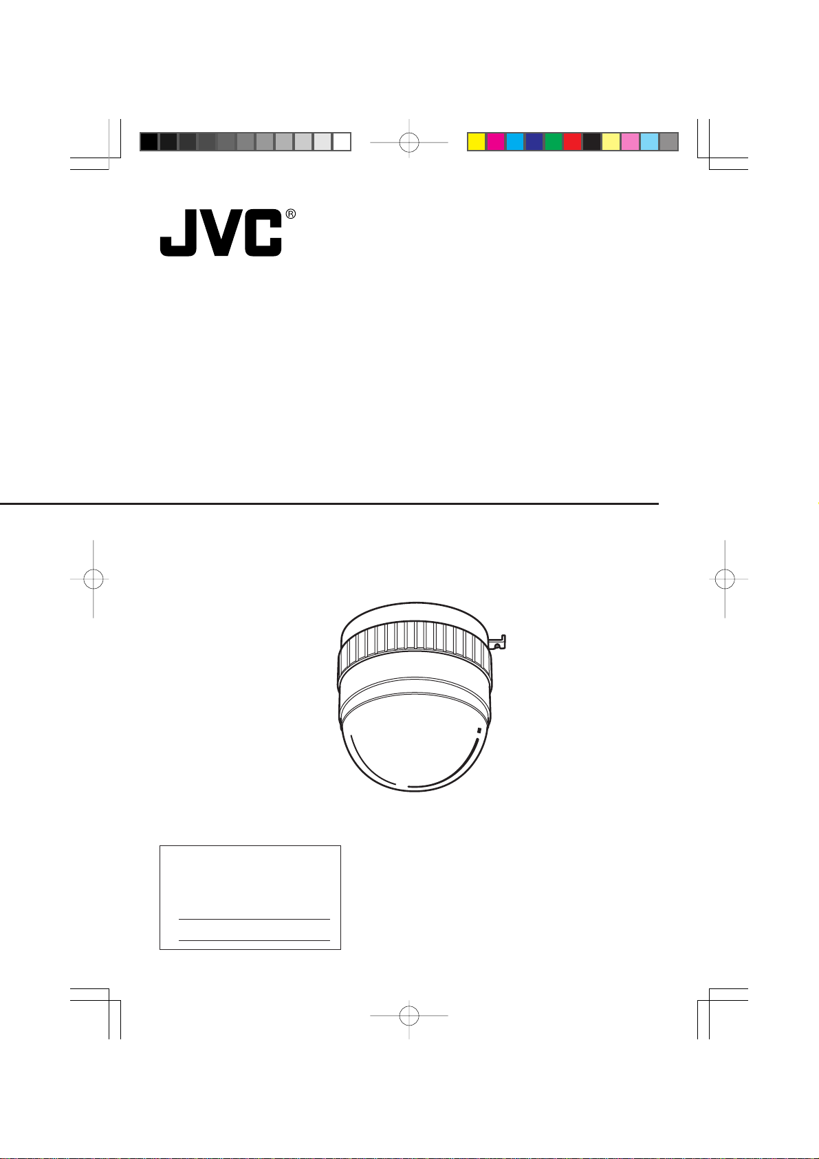
ACTIVE MOVEMENT VIDEO CAMERA
INSTRUCTIONS
TK-AM200
For Customer Use:
Enter below the Serial No. which is
located on the body. Retain this
information for future reference.
Model No. TK-AM200
Serial No.
This instruction book is made from
100% recycled paper.
SC96866-001
3
Page 2
IMPORTANT SAFEGUARDS
1. Read all of these instructions.
2. Save these instructions for later use.
3. All warnings on the product and in the operating instructions should be adhered to.
4. Unplug this appliance system from the wall outlet before cleaning. Do not use liquid cleaners or aerosol cleaners. Use a damp cloth for cleaning.
5. Do not use attachments not recommended by the appliance manufacturer as they may
cause hazards.
6. Do not use this appliance near water - for example, near a bathtub, washbowl, kitchen
sink, or laundry tub, in a wet basement, or near a swimming pool, etc.
7. Do not place this appliance on an unstable cart, stand, or table. The
appliance may fall, causing serious injury to a child or adult, and
serious damage to the appliance.
Use only with a cart or stand recommended by the manufacturer , or
sold with the appliance. Wall or shelf mounting should follow the
manufacturer’ s instructions, and should use a mounting kit appro v ed
by the manufacturer. An appliance and cart combination should be
moved with care.
Quick stops, excessive force, and uneven surfaces may cause the
appliance and cart combination to overturn.
8. Slots and openings in the cabinet and the back or bottom are provided for v entilation, and
to insure reliable operation of the appliance and to protect it from overheating, these
openings must not be blocked or covered. The openings should never be blocked by
placing the appliance on a bed, sofa, rug, or other similar surface.
This appliance should never be placed near or over a radiator or heat register . This appliance should not be placed in a built-in installation such as a bookcase unless proper
ventilation is provided.
9. This appliance should be operated only from the type of power source indicated on the
marking label. If you are not sure of the type of po wer supplied to y our home , consult y our
dealer or local power company. For appliance designed to operate from battery power,
refer to the operating instructions.
10.This appliance system is equipped with a 3-wire grounding type plug (a plug having a
third (grounding) pin). This plug will only fit into a grounding-type power outlet. This is a
safety feature . If you are unable to insert the plug into the outlet, contact your electrician to
replace your obsolete outlet. Do not defeat the safety purpose of the grounding plug.
11.For added protection for this product during a lightning storm, or when it is left unattended
and unused for long periods of time, unplug it from the wall outlet and disconnect the
antenna or cable system. This will prevent damage to the product due to lightning and
power-line surges.
12.Do not allow anything to rest on the power cord. Do not locate this appliance where the
cord will be abused by persons walking on it.
PORTABLE CART WARNING
(symbol provided by RETAC)
S3126A
2
Page 3

13.Follow all warnings and instructions marked on the appliance.
14.Do not overload wall outlets and extension cords as this can result in fire or electric shock.
15.Never push objects of any kind into this appliance through cabinet slots as they may touch
dangerous voltage points or short out parts that could result in a fire or electric shock.
Never spill liquid of any kind on the appliance.
16.Do not attempt to service this appliance yourself as opening or removing covers may
expose you to dangerous voltage or other hazards. Refer all servicing to qualified service
personnel.
17.Unplug this appliance from the wall outlet and refer servicing to qualified service personnel under the following conditions:
a. When the power cord or plug is damaged or frayed.
b. If liquid has been spilled into the appliance.
c. If the appliance has been exposed to rain or water.
d. If the appliance does not operate normally by following the operating instructions. Ad-
just only those controls that are covered by the operating instructions as improper
adjustment of other controls may result in damage and will often require extensive
work by a qualified technician to restore the appliance to normal operation.
e. If the appliance has been dropped or the cabinet has been damaged.
f. When the appliance exhibits a distinct change in performance - this indicates a need
for service.
18.When replacement parts are required, be sure the service technician has used replacement parts specified by the manufacturer that have the same char acteristics as the original part. Unauthorized substitutions may result in fire, electric shock, or other hazards.
19.Upon completion of any service or repairs to this appliance, ask the service technician to
perform routine safety checks to determine that the appliance is in safe operating
condition.
3
Page 4
Safety Precautions
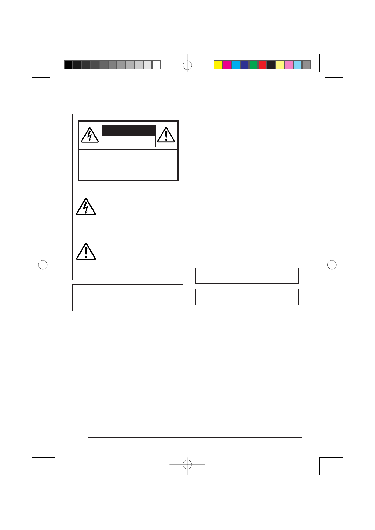
CAUTION
RISK OF ELECTRIC SHOCK
DO NOT OPEN
CAUTION:TO REDUCE THE RISK OF ELECTRIC
SHOCK. DO NOT REMOVE COVER (OR
BACK). NO USER-SERVICEABLE PARTS
INSIDE.REFER SERVICING TO
QUALIFIED SERVICE PERSONNEL.
Due to design modifications, data given in this
instruction book are subject to possible change
without prior notice.
WARNING:
TO REDUCE THE RISK OF FIRE OR
ELECTRIC SHOCK, DO NOT
EXPOSE THIS APPLIANCE TO RAIN
OR MOISTURE.
The lightning flash with arrowhead
symbol, within an equilateral triangle is
intended to alert the user to the presence of uninsulated "dangerous voltage" within the product's enclosure that
may be of sufficient magnitude to constitute a risk of electric shock to persons.
The exclamation point within an equilateral triangle is intended to alert the
user to the presence of important operating and maintenance (servicing)
instructions in the literature accompanying the appliance.
This device complies with part 15 of the FCC Rules.
Changes or modifications not approved by JVC could
void the user’s authority to operate the equipment.
AVERTISSEMENT:
POUR EVITER LES RISQUES
D’INCENDIE OU D’ELECTROCUTION, NE PAS EXPOSER
L’APP AREIL A L’HUMIDITE OU A LA
PLUIE.
INFORMATION (FOR CANADA)
RENSEIGNEMENT
This Class B digital apparatus complies with
Canadian ICES-003.
Cet appareil numérique de la Class B est
conforme á la norme NMB-003 du Canada.
(POUR CANADA)
4
Page 5

Thank you for purchasing this product.
(These instructions are for TK-AM200U.)
CONTENTS
INTRODUCTION
Features.............................................................................................................................. 6
Safety Precautions.............................................................................................................. 6
Operating Precautions........................................................................................................ 7
Controls, Connectors and Indicators...................................................................................8
Camera Body ................................................................................................................. 8
Ceiling Mount ................................................................................................................. 9
SYSTEM
RM-P2580 System............................................................................................................ 10
INSTALLATION
Connections to Terminal Board ........................................................................................ 12
Camera Settings ............................................................................................................... 14
Ceiling Installation ............................................................................................................ 16
Changing Camera Settings Using the RM-P2580
Menu Operations .............................................................................................................. 18
Menu Screen Flow............................................................................................................ 19
CAMERA MODE SELECT Screen................................................................................... 20
CAMERA VIDEO ADJUST Screen ................................................................................... 21
AWC ADJUST Screen...................................................................................................... 22
VIDEO ADJUST FOR POSI Screen................................................................................. 23
PANIC ALARM SET Screen ............................................................................................. 24
FACTORY SETTINGS Screen.......................................................................................... 24
BLC EDIT Screen ............................................................................................................. 25
CAMERA TEXT Setting.................................................................................................... 26
POSITION TEXT Setting .................................................................................................. 27
AUTO PAN Setting............................................................................................................ 28
AUTO PATROL Setting ..................................................................................................... 30
OTHERS
PANIC ALARM .................................................................................................................. 32
Specifications.................................................................................................................... 34
5
Page 6

INTRODUCTION
Features Safety Precautions
n Active mo v ement camera with integ rated
moving mechanism and camera.
n Backlight compensation function
provided. Enables improvement of video
image shot under backlit conditions.
n Electronic shutter with a selectable
shutter speed of 1/100 sec reduces
flickering caused by fluorescent lighting
in areas where the commercial power
supply frequency is 50 Hz.
n Employment of TTL automatic tracking
white balance allows use under various
light source conditions.
n Panic alarm input terminal provided.
n Electronic zoom function.
n Control possible via external control
signal conforming to the EIA/TIA RS422A or RS-485 standard. The unit can
be controlled using the optional JVC
Remote Control Unit RM-P2580.
n The following functions are available
when used in combination with the JVC
Remote Control Unit RM-P2580.
• Many kinds of function can be set using
menus.
• Camera text, position text setting.
• Auto panning function
• Auto patrol function
This function outputs the video image
at specified pre-set positions in the set
order.
Installation of this unit requires expertise.
Please contact your JVC dealer for details.
Be sure to tighten the screws and nuts used
for installation securely . Insufficient tightening
could cause the unit to fall from its mount.
6
Page 7
Operating Precautions
● To save energy, be sure to tur n off the
system when not in use.
● This camera has been designed f or indoor
use. It cannot be used outdoors.
● This camera has been designed
exclusively to be hung from the ceiling. It
may malfunction if it is placed standing
on a surface or if it is installed in a tilted
position.
● Do not install or use the camera in the
following places.
• In a place exposed to rain or water.
• In a place with vapor or oil soot, for
example in a kitchen.
• Where the temperature is outside the
allowed operating temperature range
(−10°C to 50°C).
• Near a source of radiation, X-rays,
strong radio waves or magnetism.
• In a place subjected to vibrations.
• In a place with excessive dirt.
● The camera incorporates an AGC circuit.
When it is used under low light conditions,
the camera sensitivity is automatically
boosted and the picture may look grainy.
This is not a malfunction.
● Use the ATW (auto-tracking white
balance) mode when the camera is used
under fluorescent lighting. If set to
MANUAL, the correct white balance may
not be accomplished.
● When this camera is used in the ATW
(auto-tracking white balance) mode, the
recorded colors may be slightly different
from the actual colors due to the
operational principles of the auto-tracking
white balance circuit. This is not a
malfunction.
● If a high-intensity object (such as a lamp)
is shot, the image on the screen may hav e
vertical lines (smear) or blur (blooming)
at its periphery. This is a characteristic of
the CCD; and it is not a defect.
● The camera’s electronic shutter is set to
1/60 s when shipped from the factory.
When the camera is used under
fluorescent lighting in an area with a local
power frequency of 50 Hz, please set the
shutter to 1/100 s on remote control unit.
(Sensitivity will decrease slightly at the 1/
100 s setting.)
● When dirt adheres to the dome cover , the
image will be difficult to see. Be sure to
clean the lens and the dome cover
periodically. Use a soft cloth for cleaning.
Do not use thinner, benzene, etc. If very
soiled, soak the cloth in a neutral
detergent diluted with water and wipe
clean. Then wipe with a dry cloth.
Precautions for use with the RM-P2580
● Focus (including AF) cannot be used.
● Do not select more than maximum 16
preset positions.
● ALARM TEXT EDIT 1 to EDIT 10
cannot be used.
7
Page 8
INTRODUCTION
Controls, Connectors and Indicators
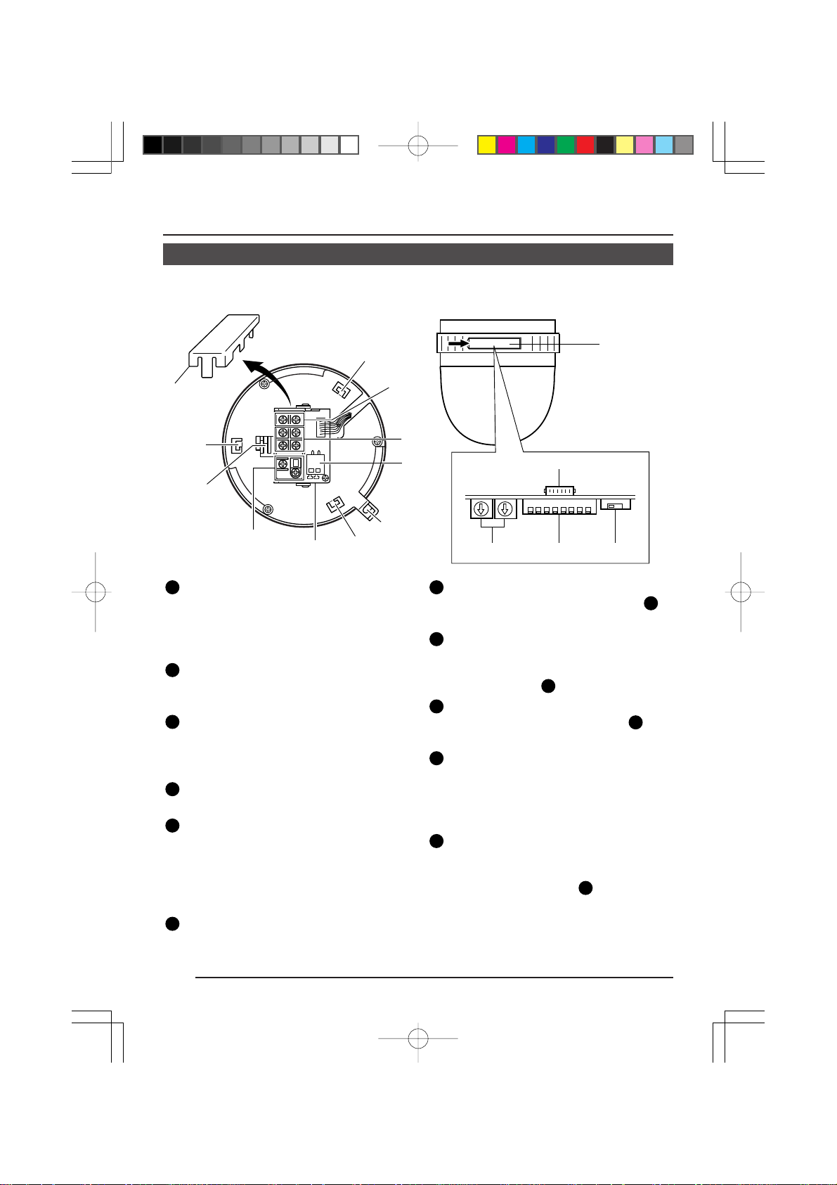
n Camera Body (With terminal board in attached condition)
(Side view)
7
6
7
9
2
1
1
Terminal board
To connect the coaxial cable used as the
video signal cable, the power cable, the
control signal cable, and the alarm input
signal cable. (Z See page 12.)
2
Video output terminal
Outputs composite video signals
(1V(p-p), output impedance 75 Ω).
3
Control signal connection terminals
Terminals for inputting signals with electrical characteristics conforming to the
EIA/TIA RS-422A or RS-485 standard.
4
AC 24 V input terminal
To input AC 24 V power.
5
Panic alarm signal input terminal
T erminal for inputting the panic alarm signal. Settings concerning the panic alarm
signal should be made using the PANIC
ALARM SET screen. (Z See pages 24
and 32.)
6
Terminal board cover
Protects the cable connection terminals
from dirt, etc.
7
8
4
3
5
0
$
#@!
7
Camera body mounting guides (×3)
To be inserted into the guide holes 16 of
the ceiling mount.
8
Camera body clamp
Fix the camera body to the ceiling mount
by fastening the ceiling mount’s camera
18
clamping screw
9
Drop prevention wire hook
Attach the drop prevention wire 20 from
the ceiling mount to this hook.
10
Switch cover
Open this cover to use the setting
switches. The cover can be opened by
pushing the cover edge in the direction
of the arrow.
11
Control signal selector switch
(RS-422A/RS-485, RS-232C)
Switches the communication mode of the
control signal terminal
• When connected to the RM-P2580, set
to the RS-422A/RS-485 side.
• When connected to a personal computer, etc. set to the RS-232C side.
to this clamp.
3
.
8
Page 9
7
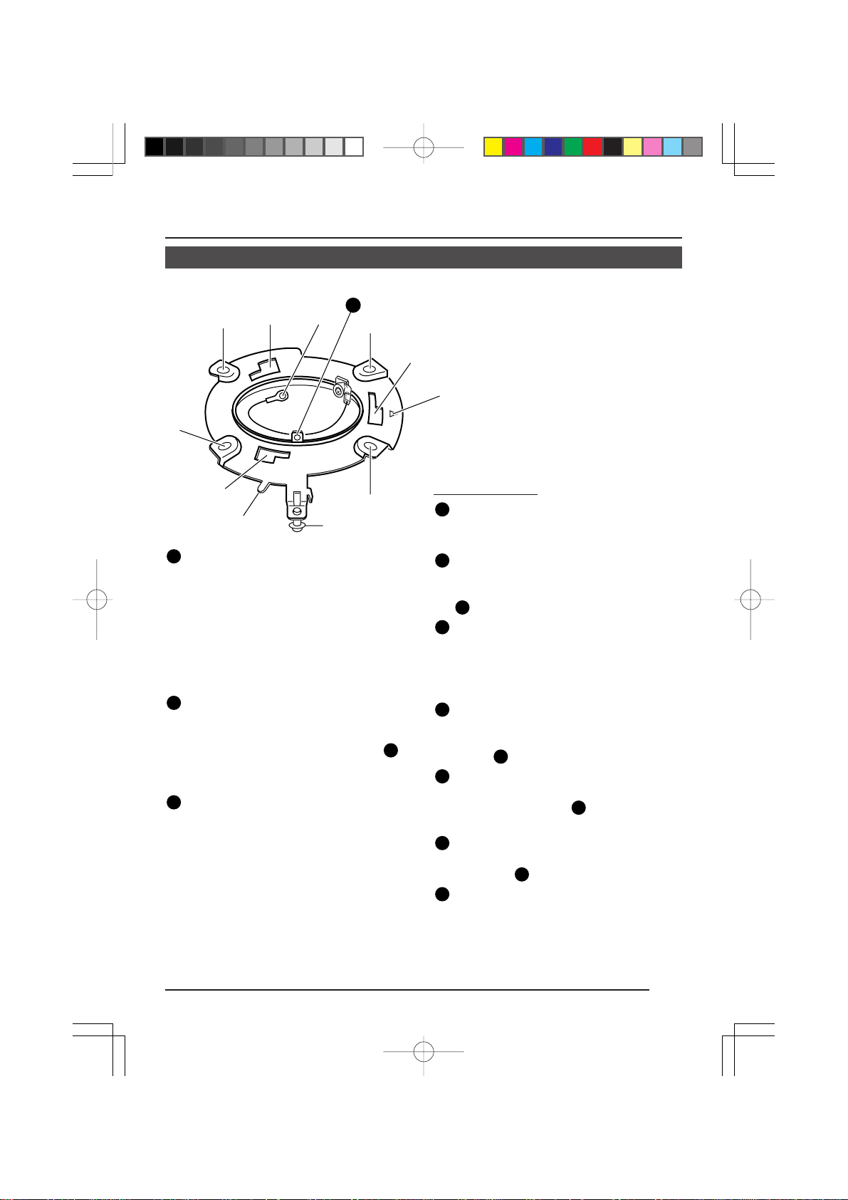
n Ceiling Mount
%
^
%
)
21
%
^
&
^
(
12
System setting switches
Set switches in accordance with the system to be connected to.
The settings comprise setting the form
of the control signal cable connection,
communication protocol, control signal
termination ON/OFF , and image synchronization method.
(Z See “Camera Settings” on page 14.)
13
Camera ID setting switches
Use to set the camera ID.
Be sure to set the camera ID when switch
1 of the system setting switches
set to ON (MULTIDROP).
(Z See “Camera Settings” on page 14.)
14
FOR SERVICE connector
Exclusively for service purposes.
%
*
12
Ceiling Mount
15
Mounting holes (×4)
Use these holes to attach the ceiling
mount to the ceiling.
16
Guide holes for mounting camera (×3)
Guide holes for mounting the camera
body. The camera body mounting guides
17
Camera direction alignment mark
When mounting the ceiling mount to the
ceiling, align this mark with the center of
the direction in which you want the camera to face.
18
Camera clamping screw
T o hold the camera body in place , be sure
is
to use this screw to clamp the camera
clamp
19
Positioning alignment protrusion
When attaching the camera body, align
the camera clamp 8 on the camera
body with this protrusion.
20
Drop prevention wire hook
Attach this wire to the drop prevention
wire hook
21
Safety wire attachment hole
To prevent the camera from accidentally
dropping down, fasten a wire from the
ceiling to this hole using an M3 screw.
(Z See “Ceiling Installation” step
page 16.)
are inserted into these holes.
8
.
9
on the camera body.
2.
on
9
Page 10
SYSTEM
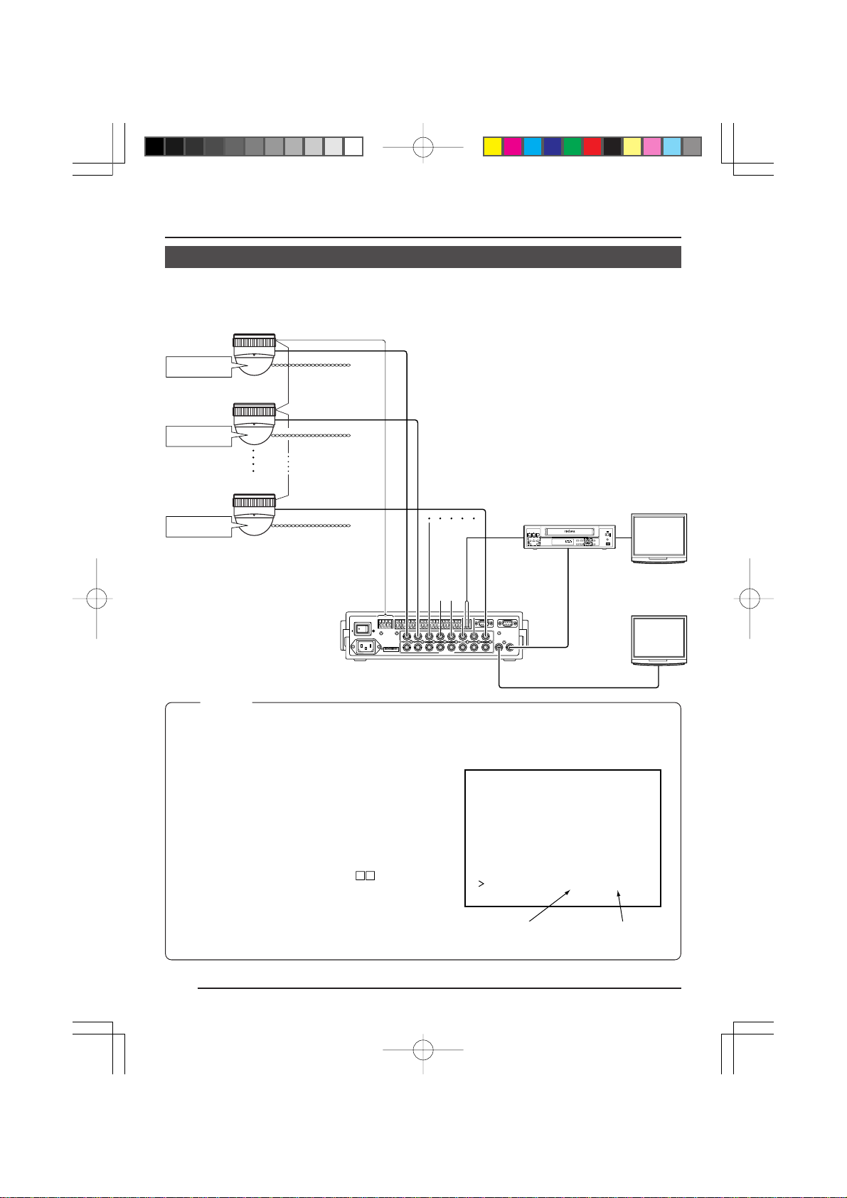
RM-P2580 System
n System with up to 8 cameras
(Sixteen position settings available for each camera.)
Camera 1
Camera ID: 01
Termination: OFF
Camera 2
Camera ID: 02
Termination: OFF
Camera 8
Camera ID: 08
Termination: ON
Camera
TK-AM200
Camera
TK-AM200
Camera
TK-AM200
Control signal cable
Video signal cable
Power cable
AC24V
AC24V
AC24V
CAM SW
OUT
Time lapse VCR
REC
REC
STOP/EJECT
CHECK
VIDEO CASSETTE RECORDER
PAUSE/
STILL
REVERSE
COUNT/
PLAY
FFREW
SHIFT/TRACKING
MENU
CLOCK
SET/V.LOCK
TIME
TIMER
MODE
REC
VIDEO IN
MONITOR
SR-L910
OPERATE
OPE. LOCK
RESET
/CANCEL
AL/PL
RESET
COMCOM
1 2 3 4 5 6 7 8
COMCOM
1
2 3 4 5 6 7
1
2 3 4 5 6 7
CAMERA
9/110/2 11/312/4 13/514/615/7 16/8
VIDEO INPUT
VIDEO OUTPUT
SW
UNIT
COMCOM COMCOM COMCOM
ALARM
AUTO
CAMERACAMERA
SW
COM
8
8
SERIAL-2SERIAL-1
MONITOR
MONITOR
OUTPUT
OUTPUT
1
2
MONITOR
OUTPUT 1
MONITOR
OUTPUT 2
MONITOR
Remote Control Unit
RM-P2580
TO
CAMERA
POWER
ON
AC INPUT
‘
TO CAMERATO CAMERA DATA I / ODATA I / O
+
+
-
-
RXRX
{
RX
|
TX
{
TX
|
OFF
4312 8756
ON
Memo:
• When operating a system using the RM-P2580, several cameras (up to 8) can be connected and
used on one control signal cable. Consequently, an incorrect switch setting on just a single camera
will cause the entire system to work incorrectly.
• Confirm switch settings on the screen as follows.
(example showing camera ID as “05”)
MONITOR screen
q Confirm that the image from the camera to be
checked is displayed on the monitor.
w Turn OFF and then ON the AC 24 V power to the
camera to be checked.
e The camera begins the initial operation and
IN TIALI
characters similar to those shown in the illustration
on the right appear on the monitor screen.
r Confirm that “DUPLEX” and “ID-
and that the ID number is the correct number (the
” are display ed
PROT OOLDUPLEXID-05C
number should be the same as the number of the
VIDEO INPUT terminal to which the camera is
connected on the rear panel of the RM-P2580).
t If wrong, set the camera ID again.
“DUPLEX” should
be displayed.
The number shown in
the □□ part of ID-□□
should be correct.
10
Page 11
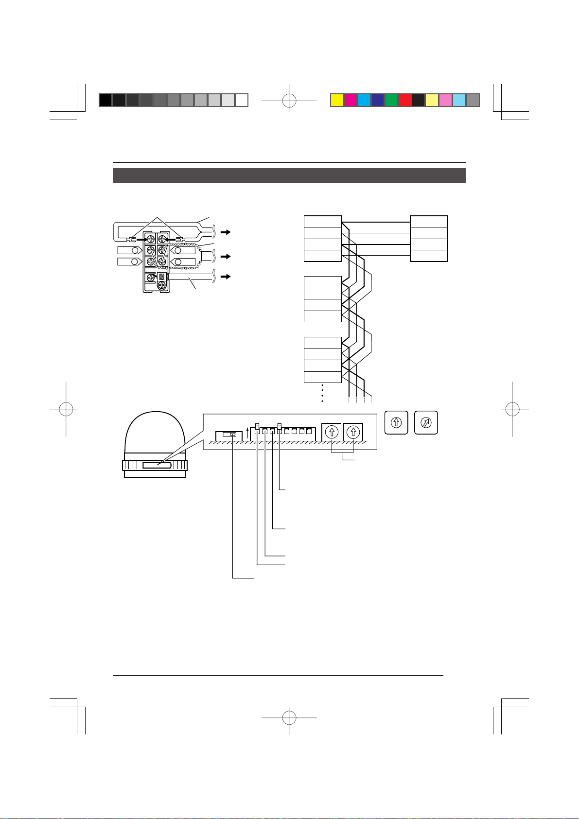
n Connections
Lug plates
RX+ C
RX– D
Terminal board
A TX+
B TX–
AC 24 V power cable
Control
signal cable
Video signal cable
(coaxial cable)
To AC 24V power
supply
To RM-P2580
T o VIDEO INPUT
terminal on
RM-P2580
Connecting the control signal cable
(
Use a twisted-pair cable for connection. Z See page 13.
Camera 1
terminal board
TX
+ A
– B
TX
RX
+ C
RX– D
Camera 2
terminal board
TX
+ A
TX
– B
+ C
RX
RX– D
Camera 3
terminal board
TX+ A
TX
– B
+ C
RX
Connect:
Camera TX+ to RM-P2580 RX+
Camera TX– to RM-P2580 RX–
Camera RX+ to RM-P2580 TX+
Camera RX– to RM-P2580 TX–
The A B C D mar ks indicated
on both the camera terminals
and the RM-P2580 terminals
facilitate correct connections.
Connect the terminals with
identical marks.
RM-P2580
A RX+
B RX–
C TX+
D TX–
RX– D
n Settings
0
9
8
7
6
(Example: Camera 1
ID “×10” position 0,
ID “×1” position 1)
When connecting
ON
1234
Switch 4: Select the synchronization method of the
Switch 3: Set this to ON (signal termination ON) only
Switch 2: Set to OFF (DUPLEX) side.
Switch 1: Set to ON (MULTIDROP) side.
Control signal selector switch:
Set to the RS-422A/RS-485 side.
Camera ID setting switches
Set to match the RM-P2580 VIDEO
INPUT terminal number for each
camera.
camera image.
Set the switch on all cameras to ON (Line
Lock) and match with the V. PHASE.
(Only possible in 60 Hz regions.)
(Z See page 20.)
on the camera placed at the end of the
control signal cable.
Set to OFF on all other cameras.
●Turn OFF the power supply to all equipment to be used before making connections.
●Carefully read the Instruction Manual for each piece of equipment to be used before
making connections.
●For the appropriate connection cables and the length of these, carefully read “Connections
to Camera Terminal Board” on page 12.
●The control signal cable cannot be used for loop connection.
0
1
5
1
9
2
4
2
8
3
3
7
4
6
5
)
11
Page 12

INSTALLATION
Connections to Terminal Board
Remove the terminal board cover
by flipping it up while pushing its
top to the left.
Turn OFF the po w er supply to all equipment
to be used before making connections.
Connections to Terminal Board
Remove the terminal board cover and
connect the video signal cable (coaxial
×
cable) (
cables (
1). Connect the AC 24 V power
×
2) and the control signal cables (×4).
When alarm input via the camera is used,
connect the alarm input cables (×2) to the
panic alarm signal input terminals.
Lug plates
Terminal board
AC 24V power cable
To AC 24V power supply
Control signal cable
RM-P2580
To switcher,
monitor, Remote
Control Unit RMVideo signal
cable (coaxial
cable)
Maximum extension (m)
CPEV , VVF, etc.
conductor diameter (mm)
CCV, etc. conductor
cross section (mm
P2580
2
)
CAUTION:
• If thin cables are used (i.e. with a high
resistance), a significant voltage drop
will occur when the unit is at its
maximum power consumption (pan, tilt,
zoom operated simultaneously). Either
use a thick cable to restrict the voltage
drop at the camera side to below 10%,
m AC 24V power supply cable
Connect the AC 24V power supply to the
AC 24V terminals on the terminal board.
To prevent connection errors or a cable
disconnection, we recommend the use of
lug plates for the connections.
The following table sho ws the connection
distances.
50 100 170 180 300 320 500
0.65 0.9 1.2 1.6 2.0
1.25 2.0
or place the power supply near to the
camera. If voltage drop occurs during
operation, the performance will be
unstable.
• Be sure not to inadvertently connect the
AC 24V cable to an AC 120 V power
supply. This could destroy the unit.
12
Page 13

Page 14

INSTALLATION
232C
422A
485
Camera Settings
Set the switches on the side of the camera in accordance with the system or equipment to
be connected to.
Always turn OFF the power before setting the switches.
1.
Open the switch cover on the side.
To open the cover, pull outward while
pressing at the edge in the direction of
the arrow.
(Be sure not to press with excessive
force as this could deform or destroy the
cover .)
2.
Set the control signal selector switch.
This switch is used to switch the input
and output signal to and from the control signal connection terminals.
When shipped from the factory, the
switch is set to “422A/485”. Nor mally,
there should be no need to change this
setting. When it becomes necessary to
change the setting, use a fine screwdriver or other difficult to break or bend
object to change the setting.
(Initial setting:
422A/485)
● 422A: Use this setting when the
485 camera is connected to the op-
tional Remote Control Unit RMP2580.
Input and output of signals with
electrical characteristics conforming to the EIA/TIA RS-422A
or RS-485 standard takes
place.
● 232C: Input and output of signals with
electrical characteristics conforming to the EIA/TIA RS232C standard takes place.
(When connecting to a personal
computer, etc.)
Memo:
The control signal selector switch setting
position and the signals input and output to and
from the control signal connection terminals are
as shown in the illustration on the left.
Improper setting could result in incorrect
operation or damage.
Control signal
selector switch
Settings for use
with RS-422A/485
RX+ (+ signal input)
RX– (– signal input)
Settings for use
with RS-232C
RXD (signal input)
Empty
Switch cover
System setting
switches
Press.
Camera ID
setting switch
TX+ (+ signal output)
TX– (– signal output)
Control signal
connection
terminals
GND (signal GND)
TXD(signal output)
14
Page 15

3.
Set system setting switches.
ON
Switches
12345678
Switch numbers
● Switch 1, 2: System connection
selector switch
Set the system connection selector
switches (Switch 1, 2) in accordance
with the equipment that the camera
body is to be connected to.
Connecting
equipment
Switch 1 Switch 2
RM-P2580 ON OFF
Memo:
Switch 1 and 2 are used to specify the
form of the control signal cable connection
between the remote control unit and the
camera and the communication protocol.
Switch 1 (Initial setting: OFF)
OFF: POINT TO POINT
ON: MULTIDR OP
Switch 2: (Initial setting: OFF)
OFF: DUPLEX
(two-way data transmission)
ON: SIMPLEX
(one-way data transmission)
● Switch 3: Termination ON/OFF
switch
This is a termination ON/OFF switch
between the “RX+” and “RX–” control
signal connection terminals.
ON: The “RX+” to “RX–” route is ter-
minated by a 110Ω resistor.
OFF: The RX+ to RX– route is not
terminated.
(Initial setting: OFF)
In a system using the Remote Control Unit
RM-P2580, set this to “ON” only on the
camera placed at the end of the control signal cable. Set to OFF on all other cameras.
ON
OFF
● Switch 4: Synchronization signal
selector switch
Switches the synchronization method
1
of the camera image.
OFF: Internal synchronization (INT)
The camera’ s vertical synchroniza-
ON:
1
tion is matched with the frequency
of the AC 24V line power supply.
When switching between mul-
tiple cameras using a switcher,
selecting this mode and adjusting the vertical phase can reduce the monitor sync disturbances occurring when the
camera image is switched. (This
cannot be used in regions where
the power frequency is 50 Hz.)
● Switches 5, 6, 7, 8
These switches are not used.
(Set them to OFF.)
4.
Camera ID setting switches
Camera ID setting is only performed
when the system connection selector
switches (Switch 1 and 2) are set to “RMP2580”.
The camera ID number is a number to
identify each of the cameras connect to
the RM-P2580. The camera ID number
should be the same as the number of
the RM-P2580 VIDEO INPUT terminal
to which the camera is connected.
Example:
The camera connected to VIDEO
INPUT 1 is set
to “01” as shown
on the right.
Memo:
If the camera ID numbers of cameras connect
to the RM-P2580 are duplicated, the system
will not work correctly.
5.
When setting of the switches is com-
0
9
8
7
6
5
Double
figures
1
2
3
4
pleted, close the cover over the setting
switches again.
"1""0"
0
9
8
7
6
5
Single
figures
1
2
4
15
3
Page 16

INSTALLATION
Ceiling Installation
1.
2.
To ceiling slab
or channel
Wire
Safety wire
attachment
hole
3.
Guide
Tab
4.
M3 screw
3.
-1)
Hook
75 mm
3.
-1)
3 mm
or
less.
Guide
Tab
3.
-2)
Connector
cable
White wire
Connector
on terminal
board
Drop prevention
wire
1.
Make a hole (75 mm diameter) in the ceiling for passing the connection cables.
2.
Attach the provided ceiling mount to the
ceiling.
● Attach the ceiling mount so that the camera direction mark is aligned with the direction in which you want the camera to f ace.
Coincide the center of the mount with the
hole (75 mm diameter) for passing the
cables through the ceiling. Attach the ceiling mount to the ceiling using 4 screws.
● Use M4 screws or bolts for attaching the
Camera
ceiling mount.
direc-
● If wood screws are used, use screws with
tion
mark
a diameter of 4.1 mm.
● The screw head height should be no more
than 3 mm.
CAUTION:
To prevent the ceiling mount and
camera from dropping down, it is
recommended to connect the ceiling
mount to a ceiling slab or channel with
a wire. Fasten the wire to the safety wire
attachment hole using an M3 screw as
shown in the illustration.
3.
Pass the wired terminal board through the
hole in the ceiling mount and attach it to the
camera body.
1) Slide the tab on the terminal board into
the guide on the camera. When the terminal board is moved in the direction of
the arrow, it is secured to the camera.
2) Connect the connector cable from the
camera body to the connector on the terminal board.
4.
Attach the drop prevention wire.
As shown in the illustration, pull the drop
prevention wire out from the ceiling mount
and attach it to the drop prevention wire
hook on the underside of the camera body.
Memo:
Bundling the drop prevention wire together with the
cables connected to the terminal board using vinyl
tape will help prevent the cables from being
pinched.
16
CAUTION
Be sure to attach the drop prevention wire. If
not attached, the camera body could drop
down.
Page 17

5.
Camera
clamp
B
Camera
clamp
Positioning
alignment
protrusion
A
Ceiling mount
Camera
Camera clamping screw
body
(Slightly loosen)
Camera clamping screw
Camera
clamping
screw
(Tighten.)
Mount the camera body.
5.
1) Ensure that the camera clamping screw
on the ceiling mount is loosened.
2) Align the ceiling mount’s positioning
alignment protrusion (A in the illustration on the left) with the camera clamp
(B in the illustration on the left) position
on the camera body and press the camera body straight against the mount.
CAUTION:
Exercise caution so as not to pinch the
drop prevention wire and the connected
cables.
3) Rotate the camera body clockwise as far
as it will go.
At this point, check that the camera body
clamp is located on the camera clamping screw on the ceiling mount.
4) Tighten the camera clamping screw.
n Changing the position of the mounted
camera body
1) Slightly loosen the camera clamping
screw. By turning the camera body
counterclockwise, the position of the
mounted camera body can be
changed within a range of approximately 40 degrees (approximately 20
degrees to the left and right).
Memo:
Loosening the camera clamping screw too
much will cause the camera body to come
off the ceiling mount.
2) After the position for the camera body
is decided, tighten the camera clamping screw.
CAUTION
Be sure to tighten the camera clamping
screw fully. Otherwise the camera body
may vibrate or drop from the ceiling.
n
To dismount the camera from the ceiling,
perform steps 3. to 5. in reverse order.
17
Page 18

Changing Camera Settings Using the RM-P2580
Menu Operations
When the RM-P2580 is used as the remote control unit, the camera’s built-in menus can be
called up and set from the remote control unit. This function is explained on this page.
(For details, refer to the Instruction Manual for the remote control unit.)
SET
MENU
button
button
CAMERA/POSITION
3
2
6
5
8
9
0
ENTER
/HOME
CAMERA
OPTION
AUTO
PAN
1
REMOTE CONTROL UNIT
AUTO F-1 F-2 F-3
POSITION
OPTION
2
AUTO
PATROL
SETUP
MENU SET
CLOSE
NEAR
WIDE
SPEED
IRIS
FOCUS
AF
ZOOM
POWER
ALARM
KEY LOCK
OPEN
FAR
TELE CLEAR
CAMERA POSITION
1
4
7
RM-P2580
SETUP
Item
cursor
POS I I ON S ETU P . .T
CAME A . .R
CONT O L U N I T . .R
SETUP screen from the remote control
SETUP
CAME A MODE SE LECT . .R
CAME A V I DEO ADJ UST . .R
VIDE ADJ FOR POSI..O
TEXT EDIT..
AUTO PATROL SET . .
AUTO PAN SET . .
PANI ALARM SET . .C
FACT RY SETTI NGS. .O
Camera SETUP screen
CAM RA MODE SEL ECTE
V.PH SE 217A
POS . EX T LOC . UP– LT
ALM. EXT SI ZE DOUBLET
BLC D IT1 . .E
BLC D IT2 . .E
Submenu sample screen
Change mark
CAM RA MODE SEL ECTE
V.PH SE 217A
POS . EX T LOC . UP–RT
ALM. EXT SI ZE DOUBLET
BLC D IT1 . .E
BLC D IT2 . .E
Sample screen after change
18
PAN/TILTLENS
RM-P2580
Power switch
on the rear
panel.
PAN/TILT
control
lever
Submenu
to be
followed
1.
Set the power switch on the rear panel of
the remote control unit to ON.
2.
When the MENU button is pressed for about
3 seconds, the LED lights up and the remote control’s SETUP screen will be output from the MONITOR OUTPUT-1 connector.
3.
Use the PAN/TILT control le ver to move the
cursor (>) and align it the CAMERA item.
● The cursor will move up when the lever is
¶
pressed up (
).
● The cursor will move down when the lever is pressed down (
4.
Press the SET button to display the SETUP
Ä).
screen of the camera.
Memo:
Items followed by “..” are items that have a
submenu.
5.
Select the item in the same manner as in
3
.
step
6.
Press the PAN/TILT control lever to the left
or to the right to change the set value of the
selected item.
● The value will become smaller when the
lever is pressed to the left (
§).
● The value will become larger when the le-
ver is pressed to the right (
©).
When the set value of an item is changed,
the change mark (
) shown in the illustra-
∗
tion on the left appears.
Memo:
For details on submenu settings, see the next
and following pages.
7.
When changes have been made, press the
MENU button to return to the higher order
menu.
● At this point, “DATA SAVED” is displayed
on the screen for about 3 seconds when
item settings have been changed.
Page 19

Menu Screen Flow
The menu screen flow is as follows. For details, see the pages referred to.
Normal screen
SETUP
POS I I ON SETUP . .T
CAME A . .R
CONT OL U N I T . .R
SETUP screen
from the remote control
SETUP
CAME A MODE SE LECT . .
R
CAME A V I DEO ADJ USTR
VIDE ADJ FOR POSI ..O
TEXT EDIT..
AUTO PATROL SE T . .
AUTO PAN SET . .
PANI A LARM SET . .C
FACT RY SETT INGS. .O
Camera SETUP screen
..
Z See page 20.
CAM RA MODE SE LECTE
V.PH SE 217A
POS . EXT LOC . UP – LT
ALM. EXT SI ZE DOUBLET
BLC DI T1. .E
BLC DI T2. .E
CAMERA MODE SELECT screen
(Used for setting functions
separately for each camera.)
Z See page 23.
ADJUEOVID ST FOR POSI
BLC ODE OFFM
W. BA ANCE ATWL
RB G I N 18 6A
MG G I N 1 9 2A
VIDEO ADJUST FOR POSI screen
(Used for setting functions related to
the image of each position.)
Z See page 30.
UTO PATROLA
PATR L1 HOME 10sO
PATR L2 POS1 10sO
PATR L3 POS2 10sO
PATR L4 POS3 10sO
PATR L5 POS4 10sO
PATR L6 POS5 10sO
PATR L7 POS6 10sO
PATR L8 POS7 10sO
WDFBW/>ZDOMO
AUTO PATROL screen
(Used for setting the auto patrol
function for automatic sequential
movement for each camera.)
Z See page 21.
CAME A V I DEO ADJ USTR
AGC ODE 1 0 dBM
SUPE AGC OFFR
SHUT ER SPEED 1 / 6 0T
ENHA CE H I GHN
AV /P AK 8 / 2E
COLO LEVEL 5R
AWC D J U S T . .A
CAMERA VIDEO ADJUST screen
(Used for settings functions related to
the video image of each camera.)
Z See pages 26 to 27.
TEXT EDI T
CAME A TREX..T
POS I I ONTEXT..T
TEXT EDIT screen
(Used for setting and editing
character strings superimposed
on the screen.)
Z See page 28.
UTOAPANSET
STAR PO SET . .TSIIONT
RETU N PO SET . .RITIONS
Z See page 24.
IC APAN LARM SET
DURA I ON 10 sT
POLA I T Y MAKER
POS I I ON POS1T
MODE AL ARM
PANIC ALARM SET screen
(Used for settings related to
the panic alarm input.)
(For returning all settings to the default values.)
AUTO PAN SET screen
(Used for settings related to
auto panning.)
Z See page 24.
TORYFAC SETT INGS
FACT RY S NOOSETINGT
FACTORY SETTINGS screen
19
Page 20

Changing Camera Settings Using the RM-P2580
CAMERA MODE SELECT Screen
Used for setting functions separately for each camera.
Item Function
V. PHASE
POS. TEXT
LOC.
ALM. TEXT
SIZE
Used to adjust and align the vertical phase
of the camera body with other cameras
operating in the Line Lock (LL) mode.
Adjust while viewing the monitor screen.
Adjustment is made by tilting the PAN/TIL T
control lever to the left or right.
Used to select the location for displaying
position text.
UP-L: Displays the text in the upper
left corner of the screen.
DOWN-L: Displays the text in the lower
left corner of the screen.
UP-C: Displays the text in the center
of the upper part of the screen.
DOWN-C: Displays the text in the center
of the lower part of the screen.
UP-R: Displays the text in the upper
right corner of the screen.
DOWN-R: Displays the text in the lower
right corner of the screen.
Used to select the size of the characters
displayed during ALARM.
ALARM
ALARM
Variable Factory
range setting
0 to 255
UP-L
DOWN-L
UP-C
DOWN-C
UP-R
DOWN-R
NORMAL
DOUBLE
127
UP-L
DOUBLE
BLC EDIT 1
BLC EDIT 2
20
NORMAL
Pressing the SET button displays the
screen (BLC EDIT 1 screen) on which the
user can set the backlight compensation
metering area.
Z See “BLC EDIT Screen” on page 25.
Pressing the SET button displays the
screen (BLC EDIT 2 screen) on which the
user can set the backlight compensation
metering area.
Z See “BLC EDIT Screen” on page 25.
DOUBLE
Page 21

CAMERA VIDEO ADJUST Screen
Used for setting functions related to the video image of each camera.
Item Function
AGC MODE
SUPER AGC
SHUTTER
SPEED
ENHANCE
AV/PEAK
Sets the maximum gain of the AGC (Automatic
Gain Control).
• Set to OFF when the AGC function is not
used.
• Set to 20 dB when illumination is par ticularly dim.
Used when the brightness is still insufficient
even if the AGC MODE is set at 20 dB.
ON: Gain level is increased.
OFF: Gain level is not increased.
∗ When SUPER AGC is ON;
• Dark areas of the screen may appear grainy.
• Gain will be set according to the setting of
the SUPER AGC with no relation to the AGC
MODE setting.
Used to set the electronic shutter speed for
each camera.
T o reduce flic kering caused by fluorescent lighting, set the electronic shutter speed to 1/100
in areas where the commercial power supply
frequency is 50 Hz, and to 1/60 in areas where
the frequency is 60 Hz.
Contour compensation function that enhances
the sharpness of the monitor screen.
LOW: Low contour enhancement
HIGH: High contour enhancement
Sets the exposure detection as a ratio of the
average value and the peak value.
• AVERAGE value large: Increase the AVERAGE value when portions other than the
highlighted areas of the screen are dark and
look corrupted. (Ex. 10/0)
• PEAK value large: Increase the PEAK value
when halation occurs in the highlighted areas of the screen. (Ex. 5/5)
Variable Factory
range setting
OFF
10 dB
20 dB
ON
OFF
1/60
1/100
LOW
HIGH
10/0
9/1
8/2
7/3
6/4
5/5
10 dB
OFF
1/60
HIGH
8/2
21
Page 22

Changing Camera Settings Using the RM-P2580
CAMERA VIDEO ADJUST Screen (Continued)
Item Function
COLOR
LEVEL
AWC
ADJUST
Used to adjust the color level of the video signal.
• T o mak e colors lighter ... Decrease the value .
• To make colors darker ... Increase the value.
Pressing the SET button displays the AWC
(One-push Auto White Balance) adjustment
screen.
Z See “AWC ADJUST Screen” below.
Variable Factory
range setting
0
(Integer
~
10
steps)
5
AWC ADJUST Screen
The white balance compensation values set on this screen are retained in camera body.
To use the saved white balance compensation values, set the W. BALANCE item on the
VIDEO ADJUST FOR POSI screen to AWC. (Z See page 23.)
1.
Select the AWC ADJUST item on the CAM-
AWC AD J U S T
ADJUST START > SET
AWC ADJUST screen
AWC O K
Normal screen
CAUTION:
• Even when the VIDEO ADJUST FOR POSI screen’ s W. BALANCE item is set to “ATW” or “MANUAL”,
the AWC adjustment on the AWC ADJUST screen is effective and the value resulting from the
AWC adjustment is stored in the camera body.
However, when the positions set by “ATW” or “MANUAL” are selected again, the image returns from
the setting determined by the value resulting from the AWC adjustment to the setting values of
“ATW” or “MANUAL”, respectively.
• AWC adjustment works separately for each position but only one adjustment value is stored, and
the value stored in the camera body is the value obtained when A WC adjustment w as last performed.
ERA VIDEO ADJUST screen. When the SET
button is pressed, the AWC ADJUST screen
is displayed.
2.
Pressing the SET button on the A WC ADJUST
screen starts AWC (white balance adjustment).
3.
When AWC adjustment is completed normally,
the compensation values are retained in the
camera body, and “AWC OK” is displayed on
the screen for about 3 seconds before the A WC
ADJUST screen returns.
The following indications are displayed if the
AWC adjustment is not accomplished correctly.
• OBJECT NG (improper object)
• HIGH LIGHT ERROR (excessive illumina-
tion)
• LOW LIGHT ERROR (insufficient illumina-
tion)
4.
T o cancel the A WC oper ation, press the MENU
button before the operation is completed normally.
22
Page 23

VIDEO ADJUST FOR POSI Screen
Used for setting functions related to the image of each position.
Item Function
BLC MODE
W. BALANCE
RB GAIN
MG GAIN
Used to select the backlight compensation function.
Used when a bright light source, etc. is placed in the
same direction as the subject.
OFF:
The backlight compensation function does not work.
AREA 1 to AREA 4:
When the SET button is pressed, the fixed light metering areas are displayed. Select one of the four types.
Light metering
area
AREA 1 AREA 2 AREA 3 AREA 4
EDIT 1 to EDIT 2:
When the SET button is pressed, the user light metering area set on BLC EDIT 1 or BLC EDIT 2 of the
CAMERA MODE SELECT screen is displayed.
Z See page 20.
• Using light metering areas
Move the light metering area so that an unnecessary light source is placed outside the area. To stop
the light metering area display, press the MENU
button.
Used for selecting the white balance adjustment function.
MANUAL: Selects the manual adjustment mode.
ATW: Automatic color temperature adjustment
AWC: Selects the AWC (One-push Auto White
Used when the white balance is adjusted manually.
Small value: Red is enhanced.
Large value: Blue is enhanced.
Used when the white balance is adjusted manually.
Small value: Magenta is enhanced.
Large value: Green is enhanced.
Light metering
(Adjustment is made in the following
items RB GAIN and MG GAIN.)
mode.
Balance) mode set for the AWC ADJUST
item on the CAMERA VIDEO ADJUST
screen.
area
Light metering
area
Light metering
area
Variable Factory
range setting
OFF
OFF
AREA 1
AREA 2
AREA 3
AREA 4
EDIT 1
EDIT 2
MANUAL
ATW
ATW
AWC
0 to 255
0 to 255
186
192
RB GAIN and MG GAIN values cannot be changed when W. BALANCE is set to
ATW or AWC.
23
Page 24

Changing Camera Settings Using the RM-P2580
PANIC ALARM SET Screen
Used for settings related to the panic alarm input. (Z See “PANIC ALARM” on page 32.)
Item Function
DURATION
Sets the duration of the alarm mode operation
when alarm signal is input.
When set to SERIES, alarm mode operation continues.
Note:
When used in a system with the RM-P2580, this
setting becomes invalid. Make the setting using
the RM-P2580 ALARM TIME option.
Variable Factory
range setting
5, 6, 7, 8, 9,
10, 15, 20,
25, 30,
60 s,
SERIES
10 s
POLARITY
POSITION
MODE
Sets the polarity of the alarm input.
MAKE: Alarm condition generated when
MAKE connected.
BREAK: Alarm condition generated when
BREAK connected.
Sets the camera position at the time of alarm
input.
Sets whether or not manual operation should
be accepted during alarm operation.
ALARM: Manual operation not accepted dur-
ing alarm operation.
MANUAL: Manual operation is accepted also
during alarm operation.
Note:
When used in a system with the RM-P2580, this
setting becomes invalid. The mode becomes the
ALARM priority mode.
FACTORY SETTINGS Screen
Used for returning all settings to the default values.
Item Function
FACTORY
SETTINGS
Used to return menu settings to the factory
settings.
YES: Returns settings to the factory settings.
NO: Settings are not returned to the factory
settings.
Memo:
When YES is selected and the SET button is
pressed, after “EXECUTING” has been
displayed for about 10 seconds on the screen,
“DATA CLEARED” is sho wn f or about 3 seconds.
Do not turn off the power during this interval.
MAKE
BREAK
HOME
POS 1 to
POS 15
ALARM
MANUAL
Variable Factory
range setting
YES
NO
MAKE
POS 1
ALARM
NO
24
Page 25

BLC EDIT Screen
This is a screen for changing the position of the light metering area used for backlight
compensation. There are two types of screens on which the light metering area can be
changed. (BLC EDIT 1 and BLC EDIT 2)
CAM RA MODE S ELECTE
V.PH SE 217A
POS . EX T LOC . UP – LT
ALM. EXT SI ZE DOUBLET
BLC D IT1 . .E
BLC D IT2 . .E
CAMERA MODE SELECT screen
BLC EDIT 1 screen
SET button
BLC EDIT 2 screen
SET button
Light metering
area
Light metering
area
MENU
button
1.
Select BLC EDIT 1 on the CAMERA
MODE SELECT screen. When the SET
button is pressed, the BLC EDIT 1
screen is displayed. (Z See page 20.)
When BLC EDIT 2 is selected and the
SET button is pressed, the BLC EDIT 2
screen is displayed. (Z See page 20.)
2.
Press the SET button to select the edges
of the light metering area to be set.
(Left/Up → Right/Down → Left/Down ...)
3.
Press the PAN/TILT control lever up,
down, left, or right to enlarge or decrease
the area occupied by the light metering
area.
4.
When done with setting of the light metering area, press the MENU button.
● The set light metering area is retained
in memory, and the CAMERA MODE
SELECT screen returns.
n To use the set light metering area, set the
BLC MODE item on the VIDEO ADJUST
FOR POSI screen to EDIT 1 or EDIT 2.
MENU SET
CLOSE
NEAR
WIDEWIDE
SETUP
SPEED
IRIS
OPEN
FOCUS
FAR
AF
TELE CLEAR
ZOOM
SET button
CAMERA POSITION
POWER
ALARM
KEY LOCKKEY LOCK
CAMERA/POSITION
2
1
5
4
7
8
0
/HOME
RM-P2580
REMOTE CONTROL UNIT REMOTE CONTROL UNIT
RM-P2580
AUTO F-1 F-2 F-3
PAN/TILTLENS
CAMERA
POSI-
3
TION
OPTION
OPTION
6
1
2
AUTO
AUTO
9
PAN
PATROL
ENTER
PAN/TILT
control
lever
25
Page 26

Changing Camera Settings Using the RM-P2580
SETUPSETUP
MENUMENU SET
SPEED
IRIS
AF
FOCUS
ZOOM
OPENOPEN
FARFAR
TELE CLEARCLEAR
/HOME/HOME
7
4
1
8
0
5
2
9
6
3
ENTERENTER
AUTO
PAN
OPTIONOPTION
1
OPTIONOPTION
2
CAMERA
POSI-POSI-
TIONTION
AUTO
PATROL
CLOSECLOSE
NEARNEAR
WIDEWIDE
AUTOAUTO F-1 F-2 F-3
PAN/TILTLENS
CAMERA/POSITION
CAMERACAMERA POSITIONPOSITION
REMOTE CONTROL UNIT REMOTE CONTROL UNIT
RM-P2580
ALARM
POWERWER
KEY LOCKKEY LOCK
CAMERA TEXT Setting
Up to 16 characters can be selected as camera text for each camera.
MENU
SET
button
button
CAME A TREX..T
POS I IONTEXT..T
Space
0123 56789ABCDEFGHI JK4
LMNOP RSTUVWXYZabc def gQ
h i j k l nopq rs t uvwxyz . , ’m
-:/
SE ECT TEXT>ZOOML
CAMERA TEXT screen
Text input area
0123 56789ABCDEFGHI JK4
LMNOP RSTUVWXYZabc def gQ
h i j k l nopq rs t uvwxyz . , ’m
-:/
CA ERM
SE ECT TEXT>ZOOML
TEXT ED IT
TEXT EDIT screen
Character area
AMER A T E XTC
AMER A T E XTC
ZOOM
(TELE)
button
ZOOM
(WIDE)
button
Numeric key
CAMERA button
PAN/TILT control lever
ENTER button
RM-P2580
n Select the camera whose text should be set.
Use the CAMERA button → Numeric key →
ENTER button to select the camera.
Z For details, see the instruction manual for
the RM-P2580.
1.
Select the CAMERA TEXT.. item on the
TEXT EDIT screen, and then press the SET
button.
● The CAMERA TEXT screen appears on
the monitor screen. Characters selected
from the character area are displayed in
the text input area.
2.
Use the ZOOM (TELE) or ZOOM (WIDE)
button to select the position in the text input
area. The position moves to the right when
the ZOOM (TELE) button is pressed, and it
moves to the left when the ZOOM (WIDE)
button is pressed.
3.
Use the PAN/TILT control le v er to select the
character to be input from the character
area.
4.
When the first character for the text has
been selected, press the ZOOM (TELE)
button.
● The first character of the text is confirmed,
and the second character can now be input (shown blinking).
5.
When the whole text has been input, press
the MENU button.
● “DATA SAVED” is shown on the monitor
for about 3 seconds, and then the TEXT
EDIT screen returns.
26
Page 27

POSITION TEXT Setting
A title can be set for the registered positions for each camera. The position text can consist
of up to 16 characters.
CAME A TREX..T
POS I IONTEXT..T
TEXT ED IT
TEXT EDIT screen
MENU
SET
button
button
REMOTE CONTROL UNIT REMOTE CONTROL UNIT
CAMERACAMERA
OPTION
1
AUTO
PAN
AUTO F-1 F-2 F-3
POSITION
OPTION
2
AUTO
PATROL
RM-P2580
PAN/TILTLENS
Numeric key
POSITION button
PAN/TILT control lever
ENTER button
CAMERA POSITION
SETUP
POWER
ALARM
MENU SET
KEY LOCK
ZOOM
(TELE)
button
ZOOM
(WIDE)
button
1.
CLOSE
NEAR
WIDE
Select the POSITION TEXT.. item on the
SPEED
IRIS
OPEN
FOCUS
AF
TELE CLEAR
ZOOM
1
4
FAR
7
RM-P2580
CAMERA/POSITION
2
3
5
6
8
9
0
ENTER
/HOME
TEXT EDIT screen, and then press the SET
button.
Space
Character area
● The POSITION TEXT screen is displayed
on the monitor. Characters selected from
the character area are displayed in the te xt
0123 56789ABCDEFGHI JK4
LMNOP RSTUVWXYZQ
h i j k l nopq rs t uvwxyz . , ’m
-:/
SITION T TEXOP
abcdef g
input area.
n Select the position for which position title
text should be set. Use the POSITION
button → Numeric key → ENTER button
to select the position.
Z For details, see the instruction manual
SE ECT TEXT>ZOOML
2.
POSITION TEXT screen
Text input area
for the RM-P2580.
Use the ZOOM (TELE) or ZOOM (WIDE)
button to select the position in the text input
area.
The position moves to the right when the
ZOOM (TELE) button is pressed, and it
moves to the left when the ZOOM (WIDE)
button is pressed.
3.
0123 56789ABCDEFGHI JK4
LMNOP RSTUVWXYZQ
h i j k l nopq rs t uvwxyz . , ’m
-:/
PO IS
SE ECT TEXT>ZOOML
SITION T TEXOP
abcdef g
Use the PAN/TILT control le v er to select the
character to be input from the character
area.
4.
When the first character for the text has
been selected, press the ZOOM (TELE)
button.
● The first character of the text is confirmed,
and the second character (shown blinking)
can now be input.
5.
To set other position text titles, select the
position and then repeat steps
2.
to 4. to
set the text.
6.
When setting of all titles is completed, press
the MENU button.
● “DATA SAVED” is shown on the monitor
for about 3 seconds, and then the TEXT
EDIT screen returns.
27
Page 28

Changing Camera Settings Using the RM-P2580
SETUPSETUP
MENUMENU SET
SPEED
IRIS
AF
FOCUS
ZOOM
OPENOPEN
FARFAR
TELE CLEARCLEAR
/HOME/HOME
7
4
1
8
0
5
2
9
6
3
ENTERENTER
AUTO
PAN
OPTIONOPTION
1
OPTIONOPTION
2
CAMERA
POSI-POSI-
TIONTION
AUTO
PATROL
CLOSECLOSE
NEARNEAR
WIDEWIDE
AUTOAUTO F-1 F-2 F-3
PAN/TILTLENS
CAMERA/POSITION
CAMERACAMERA POSITIONPOSITION
REMOTE CONTROL UNIT REMOTE CONTROL UNIT
RM-P2580
ALARM
POWERWER
KEY LOCKKEY LOCK
AUTO PAN Setting
AUTO PAN is a function that automatically swings the camera horizontally in a panning
movement. Select this setting to observe the range between two points. (Set for each
camera.)
e
g
a
m
I
r
a
t
s
t
i
s
o
p
t
a
Slowly
t
n
o
i
I
m
a
g
e
a
t
r
e
t
u
r
n
p
o
s
i
t
i
o
n
ZOOM
(TELE)
button
ZOOM
(WIDE)
button
MENU
button
SET
button
RM-P2580
Numeric key
CAMERA button
PAN/TILT control lever
ENTER button
CAME A MODE SE LECT . .R
CAME A V I DEO ADJ UST . .R
VIDE ADJ FOR POSI . .O
TEXT ED IT . .
AUTO PATROL SET . .
AUTO P AN SET . .
PANI A LARM SET . .C
FACT RY SETT INGS. .O
SETUP
CAMERA SETUP screen
UTOAPANSET
STAR PO SET. .TSIIONT
RETU N PO SE T . .RITIONS
AUTO PAN SET screen
TPOTARSSITIONSET
n Use the CAMERA button → Numeric key
→ ENTER button to select the camera to
be set for auto pan.
1.
Select the AUTO PAN SET.. item on the
camera’s SETUP screen, and then press
the SET button.
● The AUTO PAN SET screen is displayed on the monitor.
2.
Use the PAN/TILT control lever to align
the cursor (>) with the START POSITION SET. When the SET button is
pressed, the START POSITION SET
screen is displayed.
● Adjust the angle of view at the star t
position using the PAN/TILT control lever and ZOOM button.
3.
When the MENU button is pressed,
“DATA SAVED” is displayed on the
screen for about 3 seconds before the
AUTO PAN SET screen retur ns.
● The set angle of view at the start position is saved.
START POSITION SET screen
28
Page 29

NPOTURRE S I T I ON SET
RETURN POSITION SET screen
4.
Use the PAN/TILT control lever to align
the cursor (>) with the RETURN POSITION SET item. When the SET button
is pressed, the RETURN POSITION
SET screen is displayed.
● Adjust the angle of view at the return
position using the PAN/TILT control
lever.
Memo:
• Movement in the up and down direction (tilt)
and lens operation are not possible at the
stop (return) position.
• Correct setting data will not be memorized if
the SET button or MENU button is pressed
while the camera is moving. Be sure to
confirm that the camera has stopped before
pressing the SET or MENU button.
5.
When the MENU button is pressed,
“DATA SAVED” is displayed on the
screen for about 3 seconds before the
AUTO PAN SET screen retur ns.
● The set angle of view at the return position is saved.
6.
When both the start position and the
return position have been set, press the
MENU button.
● The camera’s SETUP screen returns.
n To activate the auto pan operation of the
camera, press the AUTO PAN button on
the RM-P2580.
29
Page 30

Changing Camera Settings Using the RM-P2580
AUTO PATROL Setting
The AUT O PATROL function allows you to specify multiple positions (up to 16 positions) that
the camera will move to in the specified order and observe for the specified interval.
AUTO PATROL is set for each camera.
MENU
SET
button
1
2
SETUP
4
>
ZDOMO
3
CAME A MODE SE LECT . .R
CAME A V I DEO ADJ UST . .R
VIDE ADJ FOR POSI . .O
TEXT ED IT . .
AUTO PATROL SET . .
AUTO P AN SET . .
PANI A LARM SET . .C
FACT RY SETT INGS. .O
Camera SETUP screen
AUTO PATROL screen
UTO PATROLA
PATR L 1 HOME 1
PATR L 2 POS1 0 sO
PATR L 3 POS2 0 sO
PATR L 4 POS3 0 sO
PATR L 5 POS4 0 sO
PATR L 6 POS5 0 sO
PATR L 7 POS6 0 sO
PATR L 8 POS7 0 sO
WDFBW/
PATROL No. item
Position No. setting
HOME
POS 1
~
POS 15
16
0sO
1
1
1
1
1
1
1
Observation
time
10 s
20 s
30 s
45 s
1 min
2 min
SKIP
ZOOM
(TELE)
button
ZOOM
(WIDE)
button
n Use the CAMERA button → Numeric key
1.
button
REMOTE CONTROL UNIT REMOTE CONTROL UNIT
CAMERA
OPTION
1
AUTO
PAN
AUTO F-1 F-2 F-3
POSITION
OPTION
2
AUTO
PATROL
RM-P2580
PAN/TILTLENS
Numeric key
CAMERA button
POSITION button
PAN/TILT control lever
ENTER button
MENU SET
CLOSE
NEAR
WIDE
CAMERA POSITION
SETUP
POWER
ALARM
KEY LOCK
CAMERA/POSITION
3
2
1
SPEED
IRIS
OPEN
6
5
4
FOCUS
FAR
9
8
7
AF
0
ENTER
TELE CLEAR
ZOOM
/HOME
RM-P2580
→ ENTER button to select the camera to
be set for auto pan.
Z For details, see the instruction manual
for the RM-P2580.
Select the AUTO PATROL item on the
camera’s SETUP screen, and then press
the SET button.
● The AUTO PATROL setting screen is
displayed on the monitor.
The AUTO PATROL setting screen
consists of two screens.
● When the ZOOM (TELE) button is
pressed, the next AUTO PATROL setting screen appears.
When the ZOOM (WIDE) button is
pressed, the first AUTO PATROL setting screen returns.
The PATROL 1 to 8 and 9 to 16 items
indicate the AUTO PATROL operation
order.
PATROL 1: Specifies the first position
○○○
number and the observation interval for AUTO PATROL.
PATROL 16: Specifies the last position
number and the observation interval for AUTO PATROL.
30
Page 31

The next AUTO PATROL screen
UTO PATROLA
PATR L 9 POS8 1
PATR L 1 POS9 0 sO
PATR L 1 POS1 0 sO
PATR L 1 POS1 0 sO
PATR L 1 POS1 0 sO
PATR L 1 POS1 0 sO
PATR L 1 POS1 0 sO
PATR L 1
0
1
2
3
4
5
6POS1
WDFBW/
0
1
2
3
4
50sO
>
ZDOMO
2.
Press the PAN/TILT control le ver up (¶)
or down (Ä) to align the cursor (>) with
0sO
1
1
1
1
1
1
1
the PATROL No. item to be set.
● To set the PA TR OL 9 to 16 items, press
the ZOOM (TELE) button to display the
next AUTO PATROL setting screen.
3.
Set the position number of the selected
PATROL No. item.
● Use the POSITION button → Numeric
key → ENTER button to make the setting.
4.
Set the observation interval for the selected PATROL No.
Press the PAN/TILT control lever to the
§) or to the right (©) to make the
left (
setting.
● If set to SKIP, observation will not take
place at this position.
5.
Repeat steps 2. to 4. to set the position
number and observation interval for all
the PATROL No. items.
6.
When done with the setting is completed, press the MENU button.
● “DATA SAVED” is displayed on the
monitor for about 3 seconds before the
camera SETUP screen returns.
n To start the AUTO PATROL operation,
press the AUTO PATROL button on the
RM-P2580.
31
Page 32

OTHERS
PANIC ALARM
By inputting an alarm signal through the panic alarm signal input terminal (Z See page
13.), a specified position can be invoked from which surveillance is then conducted.
The camera can be set so that the PANIC ALARM operation overrides manual operation,
AUT O PATROL operation and AUTO PATROL operation by terminating these. By installing a
switch near the camera, a single press in an emergency situation will effect immediate
observation of an important surveillance point.
1.
Connecting the Alarm Signal (Z See page 13.)
● Supply a no-voltage contact signal to the panic
alarm signal input terminal.
ALARM 1
ALARM 2
2.
Setting of Alarm Signal Polarity (POLARITY)
Match the setting with that of the alarm generating contact (switch). (Z See page 24.)
When the contact closes (short), the alarm condition is
generated:
When the contact opens (open), the alarm condition is
generated:
Be sure not to supply voltage or connect to other
apparatus (open collector terminal, etc.).
This could result in incorrect operation or damage.
● By linking multiple contacts (switches), as
shown in the illustration, the alarm condition
can be activated when any of the contacts
comes on.
Memo:
Ensure that the maximum line resistance value
becomes 100 Ω or less inside the alarm circuit
(ALARM IN1 ~ alarm generating switch ~ ALARM
IN2). If the resistance is large, the alarm may not
work correctly.
Set to MAKE.
Set to BREAK.
32
Page 33

Memo:
Minimum 70 ms or more is required for the camera body to detect the switched condition of the
contact.
Example: In the case of MAKE
SHORT
Alarm detection
OPEN
Alarm detection not
guaranteed
70 ms or
more
3.
Setting of Alarm Condition Duration (DURATION)
70 ms
Set how long the alarm condition should last from when the alarm signal is supplied.
(Z See page 24.)
Memo:
When a new alarm signal is input during the alarm condition, the alarm condition is prolonged.
4.
Setting the Alarm Position (POSITION)
Set the preset position to be invoked when the alarm condition is generated.
(ZSee page 24.)
5.
Setting the Alarm Text Size (ALM. TEXT SIZE)
The “ALARM” text indication can be displayed on the screen to indicate the alarm condition when this is generated. The size of the characters should be set. (ZSee page
20.)
33
Page 34

OTHERS
Specifications
n Camera
Signal system: NTSC standard
Image device: IT CCD
Effective picture elements:
380,000 pixels,
(H) 768 × (V) 494
Image size: 1/4”
Sync system: Internal
Line lock (Only possible
in 60 Hz regions.)
Scanning frequency:
Horizontal: 15.734 kHz
Vertical: 59.94 Hz
Horizontal resolution:
470 TV lines
Video S/N: 50 dB (typical) ...
(AGC OFF)
Minimum illumination:
4 lx (F1.0, AGC 20 dB,
Y: 25%)
White balance: ATW (auto tracking)/AWC
(auto white control)
Manual (2-axis system)
Electronic shutter
Electronic zoom
Character display:
Backlight compensation:
Color level adjustment:
Contour compensation:
: 1/60 s (standard)
1/100 s (50 Hz flickerless)
:Possible (×2)
Possible
Availab le by adjustment of
light metering area posi-
tion.
Possible
Horizontal, vertical
n Moving mechanism
Panning: ±30°
Panning speed
Tilting: 0° to 60° (from down to
Tilting speed: 2°/s, 4°/s, 6°/s, 12°/s , 20°/s,
: 2°/s, 4°/s, 6°/s, 12°/s, 20°/s,
40°/s, 60°/s, 80°/s (in
MANUAL mode)
4°/s (AUTO PAN mode)
120°/s (Preset maximum)
horizontal direction)
40°/s, 60°/s, 80°/s (in
MANUAL mode)
120°/s (Preset maximum)
n General
Pow er requirement:
AC 24V 50/60Hz, 9.0W
Communications port:
RS-422A/RS-485 or
RS-232C (switchable)
9600 bit/s
Ambient temperature:
–
10°C to 50°C (operating)
0°C to 40°C (recommended)
Mass: 0.8 kg (including ceiling
mount)
Accessories: Instructions × 1
Warranty Card × 1
Service Information Card
Ceiling Mount × 1
Terminal Board × 1
× 1
n Lens
Focal length: f = 2.2 mm
Max. aperture ratio:
F1.0
34
Page 35

n External dimensions [Unit: mm]
ø75
Terminal board
1
(26)
Mounting hole ø75
46
83.5
Mounting hole
in ceiling
4-ø4.5
ø110
Camera body
ø65
46
83.5
Ceiling mount
• Design and specifications are subject to change without notice.
135
35
Page 36

TK-AM200 ACTIVE MOVEMENT VIDEO CAMERA
VICTOR COMPANY OF JAPAN, LIMITED
®
is a registered trademark owned by VICTOR COMPANY OF JAPAN, LTD.
®
is a registered trademark in Japan, the U.S.A., the U.K. and many other countries.
© 1999 VICTOR COMPANY OF JAPAN, LIMITED
Printed in Japan
SC96866-001
 Loading...