

Page 1
MB112200312
SERVICE MANUAL
DVD DIGITAL CINEMA SYSTEM
TH-M65
Area suffix
US ---------------------- Singapore
UW ---------- Brazil,Mexico,Peru
UJ --------------------- U.S.Military
UG - Turkey,South Africa,Egypt
XV-THM65
SP-PWM65 SP-THM65C SP-THM65F SP-THM65F SP-THM65F SP-THM65F
TABLE OF CONTENTS
1 PRECAUTION. . . . . . . . . . . . . . . . . . . . . . . . . . . . . . . . . . . . . . . . . . . . . . . . . . . . . . . . . . . . . . . . . . . . . . . . . 1-3
2 SPECIFIC SERVICE INSTRUCTIONS. . . . . . . . . . . . . . . . . . . . . . . . . . . . . . . . . . . . . . . . . . . . . . . . . . . . . . 1-6
3 DISASSEMBLY . . . . . . . . . . . . . . . . . . . . . . . . . . . . . . . . . . . . . . . . . . . . . . . . . . . . . . . . . . . . . . . . . . . . . . . 1-7
4 ADJUSTMENT . . . . . . . . . . . . . . . . . . . . . . . . . . . . . . . . . . . . . . . . . . . . . . . . . . . . . . . . . . . . . . . . . . . . . . . 1-35
5 TROUBLESHOOTING . . . . . . . . . . . . . . . . . . . . . . . . . . . . . . . . . . . . . . . . . . . . . . . . . . . . . . . . . . . . . . . . . 1-40
COPYRIGHT © 2003 VICTOR COMPANY OF JAPAN, LIMITED
No.MB112
2003/12
Page 2
SPECIFICATION
Center unit (XV-THM65)
Audio Audio input sensitivity/Impedance (at 1 kHz), Total Harmonic Distortion 0.02 %
NOTE : This value is measured at System cord CONNECTOR for reference.
Analog input AUDIO IN (VCR) 290 mV/47 KΩ
MIC 4.3 mV/600 Ω
Digital input* DIGITAL IN (DBS) -21 dBm to -15 dBm
(OPTICAL) (660 nm E30 nm)
* Corresponding to Linear PCM, Dolby Digital, and DTS Digital Surround (with sampling frequency - 32 kHz, 44.1 kHz, 48 kHz)
Digital output DIGITAL OUT -21 dBm to -15 dBm
(OPTICAL) (660 nm E30 nm)
Video Color System NTSC/PAL selectable
Horizontal Resolution 500 lines
Signal-to-Noise Ratio 64 dB
Video output level Composite 1.0 V(p-p)/75 Ω
S-video-Y 1.0 V(p-p)/75 Ω
S-video-C 0.286 V(p-p)/75 Ω
Component-Y 1.0 V(p-p)/75 Ω
Component-PB/PR 0.7 V(p-p)/75 Ω
Video input sensitivity/
Impedance (VCR IN)
Tuner Tuning Range FM 87.50 MHz to 108.00 MHz
General Power Requirements AC 110 - 230 V , 50 Hz/60 Hz
Power Consumption 20 W (at operation) 1.6 W (in standby mode)
Dimensions (W × H × D) 400 mm × 85 mm × 386 mm
Mass 4.6 kg
Amplifier Front/Center/Surround 80 W per channel, RMS at 6 Ω at 1 kHz, with 10 % total harmonic distortion.
Subwoofer 120 W, RMS at 4 Ω at 100 Hz, with 10 % total harmonic distortion.
Speaker Speaker unit 20 cm Bass-reflex, Magnetically Shielded
Frequency Range 25 Hz to 200 Hz
General Power Requirements AC 110 V/127 V/220 - 230 V selectable with the voltage selector, 50 Hz/60 Hz
Power Consumption 150 W (at operation) 0 W (in standby mode)
Dimensions (W × H × D) 235 mm × 355 mm × 492 mm
Mass 13.0 kg
Speakers 5.5 cm × 2 Bass-reflex, Magnetically Shielded
Power Handling Capacity 80 W
Impedance 6 Ω
Frequency Range 90 Hz to 20 kHz
Dimensions (W × H × D) 250 mm × 1 103 mm × 250 mm
Mass 3.77 kg
Speakers 5.5 cm × 2 Bass-reflex, Magnetically Shielded
Power Handling Capacity 80 W
Impedance 6 Ω
Frequency Range 90 Hz to 20 kHz
Dimensions (W × H × D) 258 mm × 75 mm × 81 mm
Mass 0.95 kg
Designs & specifications are subject to change without notice.
Composite 1.0 V(p-p)/75 Ω
S-video-Y 1.0 V(p-p)/75 Ω
S-video-C 0.286 V(p-p)/75 Ω
AM 531 kHz to 1 602 kHz (at 9 kHz intervals)
530 kHz to 1 600 kHz (at 10 kHz intervals)
Subwoofer (SP-PWM65)
Satellite Speakers (SP-THM65F)
Center Speaker (SP-THM65C)
1-2 (No.MB112)
Page 3
SECTION 1
PRECAUTION
1.1 Safety Precautions
(1) This design of th is product contains special hardw are and
many circuits and components specially for safety purposes. For continued protection, no changes should be made
to the original design unless authorized in writing by the
manufacturer. Replacement parts must be identical to
those used in the original circuits. Services should be performed by qualified personnel only.
(2) Alterations of the design or circuitry of the product should
not be made. Any design alterations of the product should
not be made. Any design alterations or additions will void
the manufacturers warranty and will further relieve the
manufacture of responsibility for personal injury or property
damage resulting therefrom.
(3) Many electrical and mechanical parts in the products have
special safety-related characteristics. These characteristics are often not evident from visual inspection nor can the
protection afforded by them necessarily be obtained by using replacement components rated for higher voltage, wattage, etc. Replacement parts which have these special
safety characteristics are identified in the Parts List of Service Manual. Electrical components having such features
are identified by shading on the schematics and by ( ) on
the Parts List in the Service Manual. The use of a substitute
replacement which does not have the same safety characteristics as the recommended replacement parts shown in
the Parts List of Service Manual may create shock, fire, or
other hazards.
(4) The leads in the products are routed and dressed with ties,
clamps, tubings, barriers and the like to be separated from
live parts, high temperature parts, moving parts and/or
sharp edges for the prevention of electric shock and fire
hazard. When service is required, the original lead routing
and dress should be observed, and it should be confirmed
that they have been returned to normal, after reassembling.
(5) Leakage shock hazard testing
After reassembling the product, always perform an isolation check on the exposed metal parts of the product (antenna terminals, knobs, metal cabinet, screw heads,
headphone jack, control shafts, etc.) to be sure the product
is safe to operate without danger of electrical shock.Do not
use a line isolation transformer during this check.
• Plug the AC line cord directly into the AC outlet. Using a
"Leakage Current Tester", measure the leakage current
from each exposed metal parts of the cabinet, particularly any exposed metal part having a return path to the
chassis, to a known good earth ground. Any leakage current must not exceed 0.5mA AC (r.m.s.).
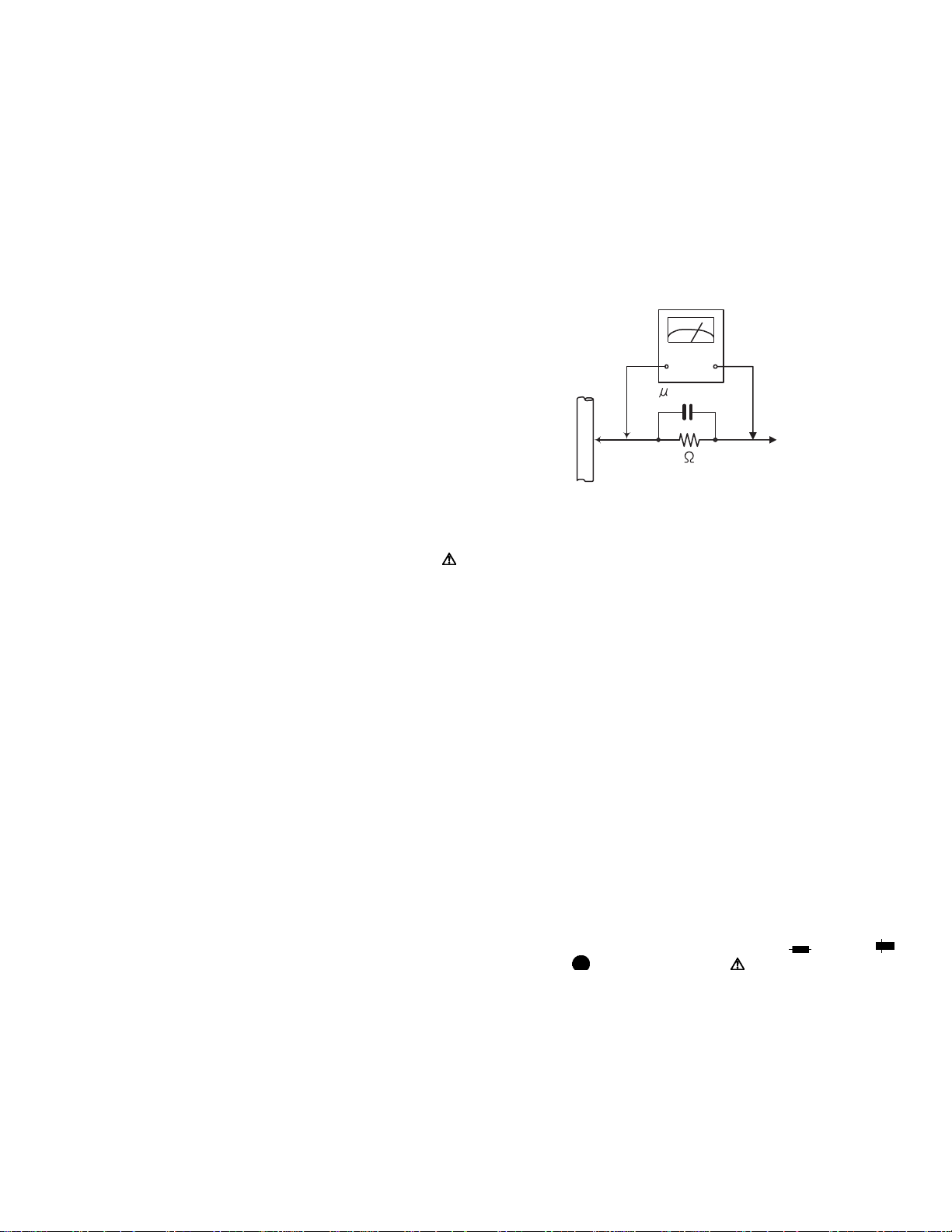
• Alternate check method
Plug the AC line cord directly into the AC outlet. Use an
AC voltmeter having, 1,000Ω per volt or more sensitivity
in the following manner. Connect a 1,500Ω 10W resistor
paralleled by a 0.15µF AC-type capacitor between an exposed metal part and a known good earth ground.
Measure the AC voltage across the resistor with the AC
voltmeter.
Move the resistor connection to each exposed metal
part, particularly any exposed metal part having a return
path to the chassis, and measure the AC voltage across
the resistor. Now, reverse the plug in the AC outlet and
repeat each measurement. Voltage measured any must
not exceed 0.75 V AC (r.m.s.). This corresponds to 0.5
mA AC (r.m.s.).
AC VOLTMETER
(Having 1000
ohms/volts,
or more sensitivity)
0.15 F AC TYPE
Place this
probe on
1500 10W
Good earth ground
1.2 Warning
(1) This equipment has been designed and manufactured to
meet international safety standards.
(2) It is the legal resp onsibility of the repairer to ensure that
these safety standards are maintained.
(3) Repairs must be made in accordance with the relevant
safety standards.
(4) It is essential that safety critical compone nts are replaced
by approved parts.
(5) If mains voltage selector is provided, check setting for local
voltage.
1.3 Caution Burrs formed during molding may be left over on some parts
of the chassis.
Therefore, pay attention to such burrs in the case of preforming repair of this system.
1.4 Critical parts for safety
In regard with component parts appearing on the silk-screen
printed side (parts side) of the PWB diagrams, the parts that are
printed over with black such as the resistor ( ), diode ( )
and ICP ( ) or identified by the " " mark nearby are critical
for safety. When replacing them, be sure to use the parts of the
same type and rating as specified by the manufacturer.
(This regulation dose not Except the J and C version)
each exposed
metal part.
(No.MB112)1-3
Page 4
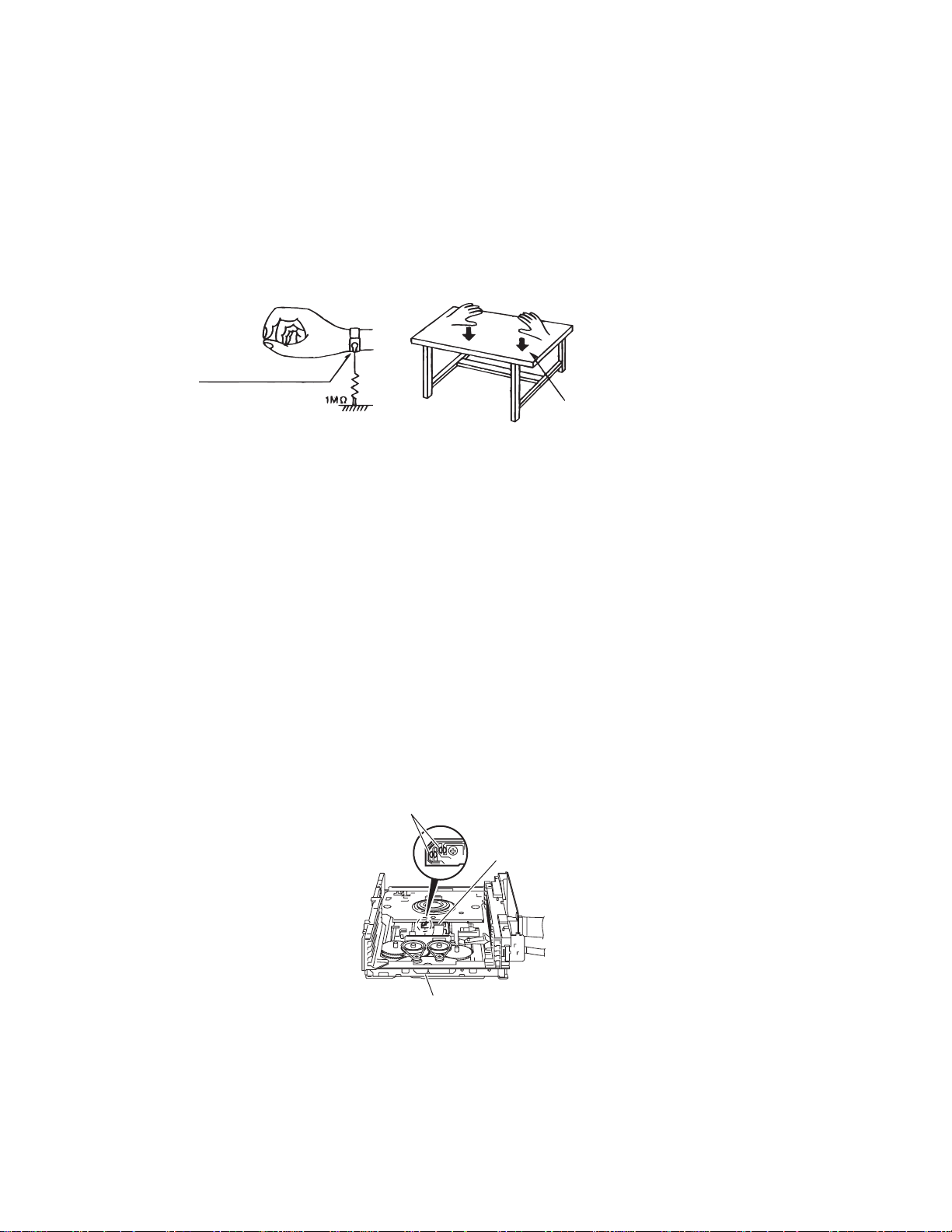
1.5 Preventing static electricity
1.5.1 Grounding to prevent damage by static electricity
Electrostatic discharge (ESD), which occurs when static electricity stored in the body, fabric, etc. is discharged, can destroy the laser
diode in the traverse unit (optical pickup). Take care to prevent this when performing repairs.
1.5.2 About the earth processing for the des t ruction prevention by static electricity
Static electricity in the work area can destroy the optical pickup (laser dio de) in devices such as DVD players.
Be careful to use proper grounding in the area where repairs are being performed.
(1) Ground the workbench
Ground the workbench by laying conductive material (such as a conductive sh eet) or an iron plate over it before placing the
traverse unit (optical pickup) on it.
(2) Ground yourself
Use an anti-static wrist strap to release any static electricity built up in your body.
(caption)
Anti-static wrist strap
Conductive material
(conductive sheet) or iron plate
1.5.3 Handling the optical pickup
(1) In order to maintain quality during transport and before installation, both sides of the laser diode on the replacement optical pick-
up are shorted. After replacement, return the shorted parts to their orig inal condition. (Refer to the text.)
(2) Do not use a tester to che ck the condition of the laser diode in the optical pickup. The tester's internal power source can easily
destroy the laser diode.
1.5.4 Handling the traverse unit (optical pickup)
(1) Do not subject the traverse unit (optical pickup) to strong shocks, as it is a sensitive, complex unit.
(2) Remove solder of the short lands on the flexible wire after replacing the optical pickup. For specific details, refer to the replace-
ment procedure in the text. Remove the anti-static pin when replacing the traverse unit.
Be careful not to take too long a time when attaching it to the connector.
(3) Handle the flexible wire carefully as it may break when subjected to strong force.
(4) It is not possible to adjust the semi-fixed resistor that adjusts the laser power. Do not turn it.
1.5.5 Attention when traverse unit is dec omp osed
*Please refer to "Disassembly method" in the text for the DVD pickup.
• Apply solder to the short circuit points before the flexible wire is disconnected from the connector on the DVD pickup.
(If the flexible wire is disconnected without applying solder, the DVD pickup may be destroyed by static electri city.)
• In the assembly, be sure to remove solder from the short circuit points after connecting the flexible wire.
Short circuit points
DVD pickup
DVD changer mechanism assembly
1-4 (No.MB112)
Page 5
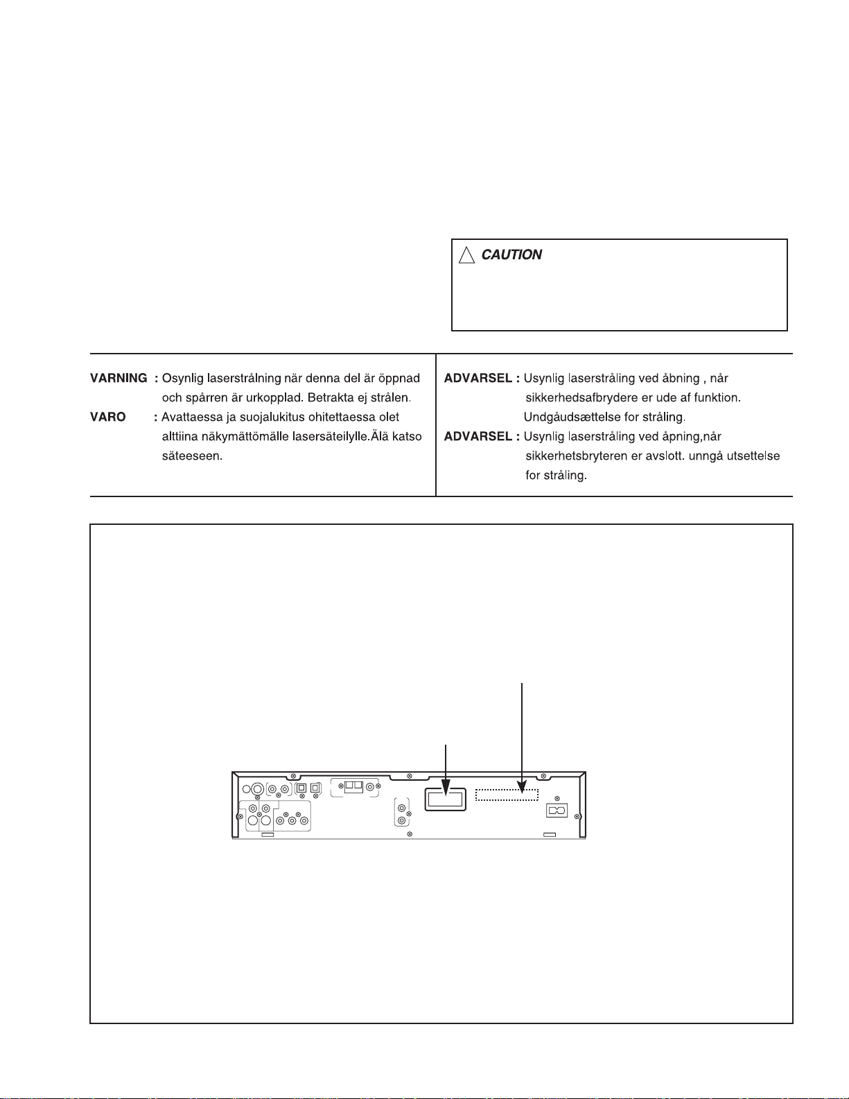
1.6 Important for laser products
1.CLASS 1 LASER PRODUCT
2.DANGER : Invisible laser radiation when open and
inter lock failed or defeated. Avoid direct exposure to
beam.
3.CAUTION : There are no serviceable parts inside the
Laser Unit. Do not disassemble the Laser Unit.
Replace the complete Laser Unit if it malfunctions.
4.CAUTION : The compact disc player uses invisible
laserradiation and is equipped with safety switches
whichprevent emission of radiation when the drawer
is open and the safety interlocks have failed or are
de
feated. It is dangerous to defeat the safety switches.
5.CAUTION : If safety switches malfunction, the laser is
able to function.
6.CAUTION : Use of controls, adjustments or
performance of procedures other than those specified
herein may result in hazardous radiation exposure.
!
Please use enough caution not to
see the beam directly or touch it
in case of an adjustment or operation
check.
REPRODUCTION AND POSITION OF LABELS
CLASS 1 LASER PRODUCT LABEL
CLASS 1
LASER PRODUCT
WARNING LABEL
(Inside)
(No.MB112)1-5
Page 6

SECTION 2
SPECIFIC SERVICE INSTRUCTIONS
This service manual does not describe SPECIFIC SERVICE INSTRUCTIONS.
1-6 (No.MB112)
Page 7
SECTION 3
r
r
DISASSEMBLY
3.1 Main body section
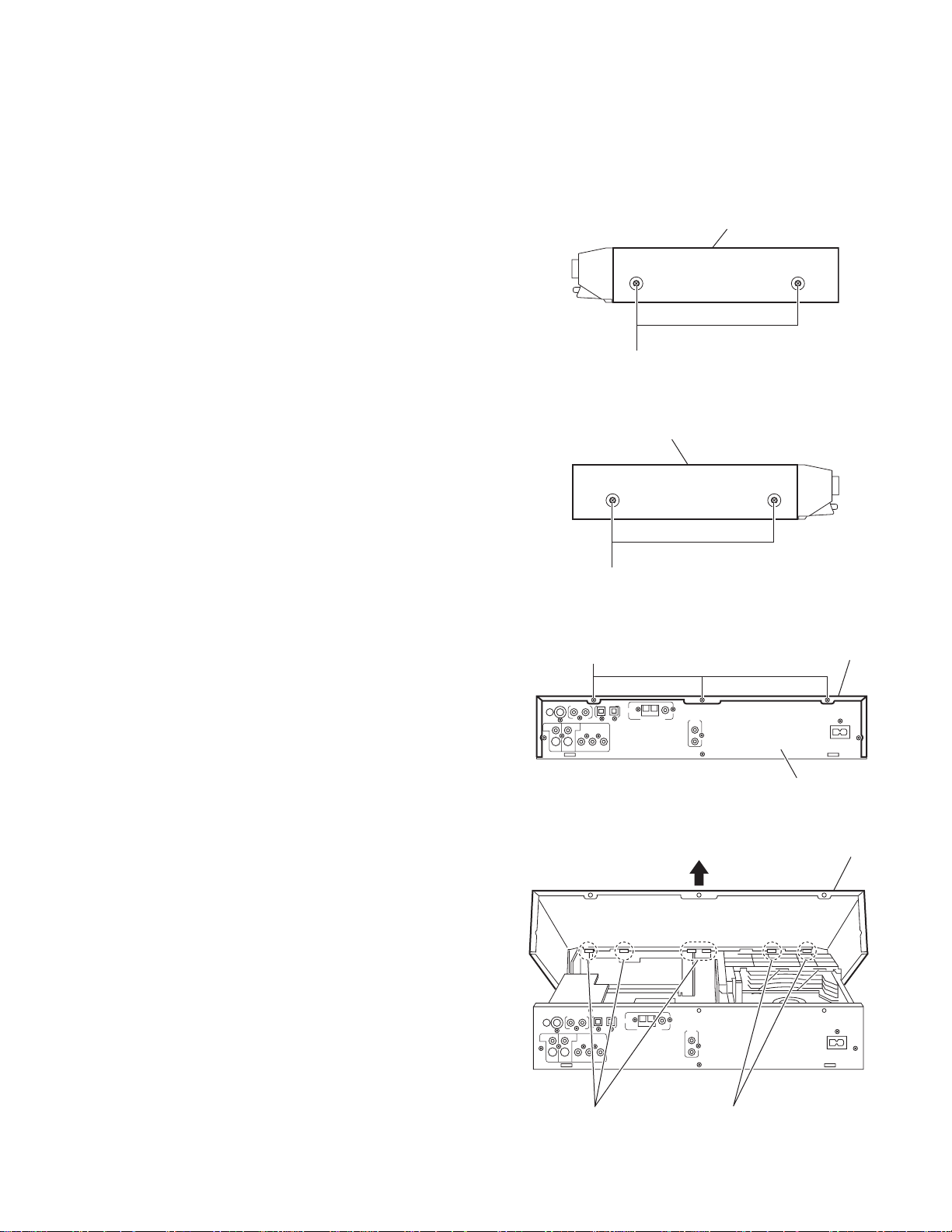
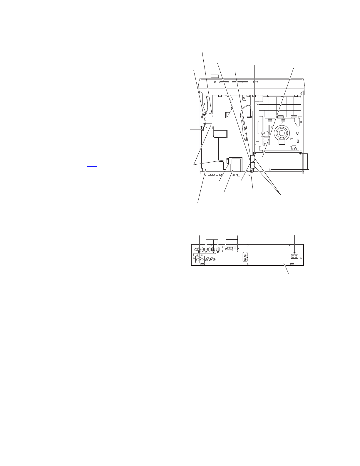
3.1.1 Removing the metal co ver
(See Figs.1 to 4)
(1) From the right and left sides of the main body, remove the
four screws A attaching the metal cover. (See Figs.1 and
2.)
(2) From the back side of the main bo dy, remove the three
screws B attaching the metal cover. (See Fig.3.)
(3) Lift the rear section of the metal cover in the direction of the
arrow while extending the lower sections of the metal
cover, release the claws a using a longer screwdriver from
the inside as required. (See Fig.4.)
Note:
Do not damage any parts and boards inside the main body
when releasing the joints a using a longer screwdriver.
Metal cover
A
Fig.1
Metal cover
A
Fig.2
B
Fig.3
Metal cove
Rear panel
Metal cove
Claws a Claws a
Fig.4
(No.MB112)1-7
Page 8
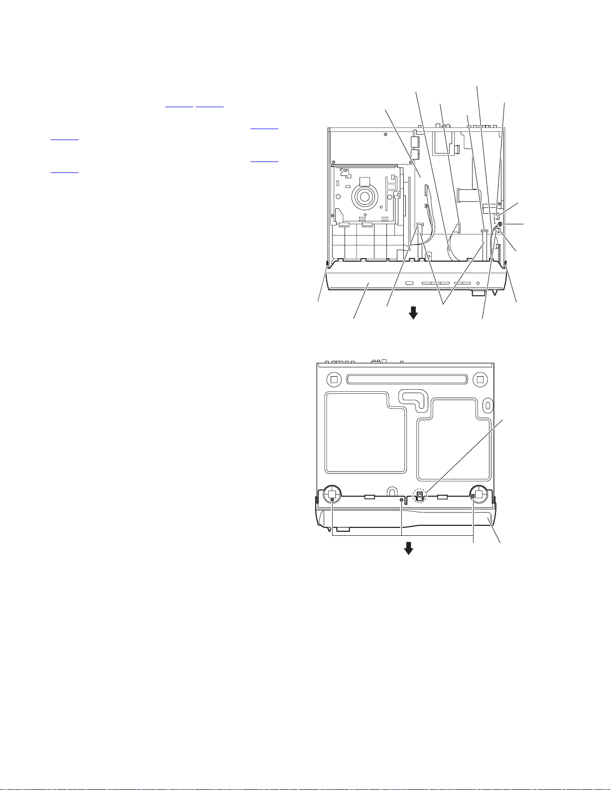
3.1.2 Removing the front panel assembly
(See Figs.5 and 6)
• Prior to performing the following procedures, remove the metal
cover.
(1) From the top side of the main body, disconnect the parallel
wires from the connectors (CN408
board. (See Fig.5.)
(2) Disconnect the card wires from the connectors (CN407
) on the main board. (See Fig.5.) [US/UW/UG
CN413
version]
(3) Disconnect the card wires from the connectors (CN407
) on the main board. (See Fig.5.) [UJ version]
CN412
(4) Remove the screw C attaching the earth wire to the main
board. (See Fig.5.)
(5) From the bottom side of the main body, remove the three
screws D attaching the front panel assembly. (See Fig.6.)
(6) Release the two hooks b and hook c from the both and
bottom sides of the main body, and remove the front panel
assembly in the direction of the arrow. (See Figs.5 and 6.)
,CN409) on the main
CN407
Earth wire
Card wire
CN409
CN412
Card wire
Main board
,
,
C
CN413
Hook b
Front panel assembly
CN408
Parallel wires
Fig.5
Fig.6
Card wire
Front panel
D
assembly
Hook b
Hook c
1-8 (No.MB112)
Page 9
3.1.3 Removing the DVD changer mechanism assembly
(See Fig.7)
• Prior to performing the following procedures, remove the metal
cover and front panel assembly.
(1) From the top side of the main bo dy, disconnect the card
wires from the connectors (CN405
board.
(2) Remove the four screws E attaching the DVD changer
mechanism assembly to the bottom chassis.
(3) Take out the DVD changer mechanism assembly in an
upward direction.
Note:
When attaching the screw E, fit the hole of the DVD changer
mechanism assembly to the bosses d on the bottom chassis.
,CN415) on the main
DVD changer mechanism
assembly
E
Boss d
E
Main board
Boss d
CN405
CN415
Card wires
3.1.4 Removing the rear p anel
(See Fig.8)
• Prior to performing the following procedure, remove the metal
cover.
(1) From the back side of the main body, remove the screw F,
ten screws G and three screws H attaching the rear panel.
E
Fig.7
Bottom chassis
FG
HH
G
H
Fig.8
Rear panel
(No.MB112)1-9
Page 10
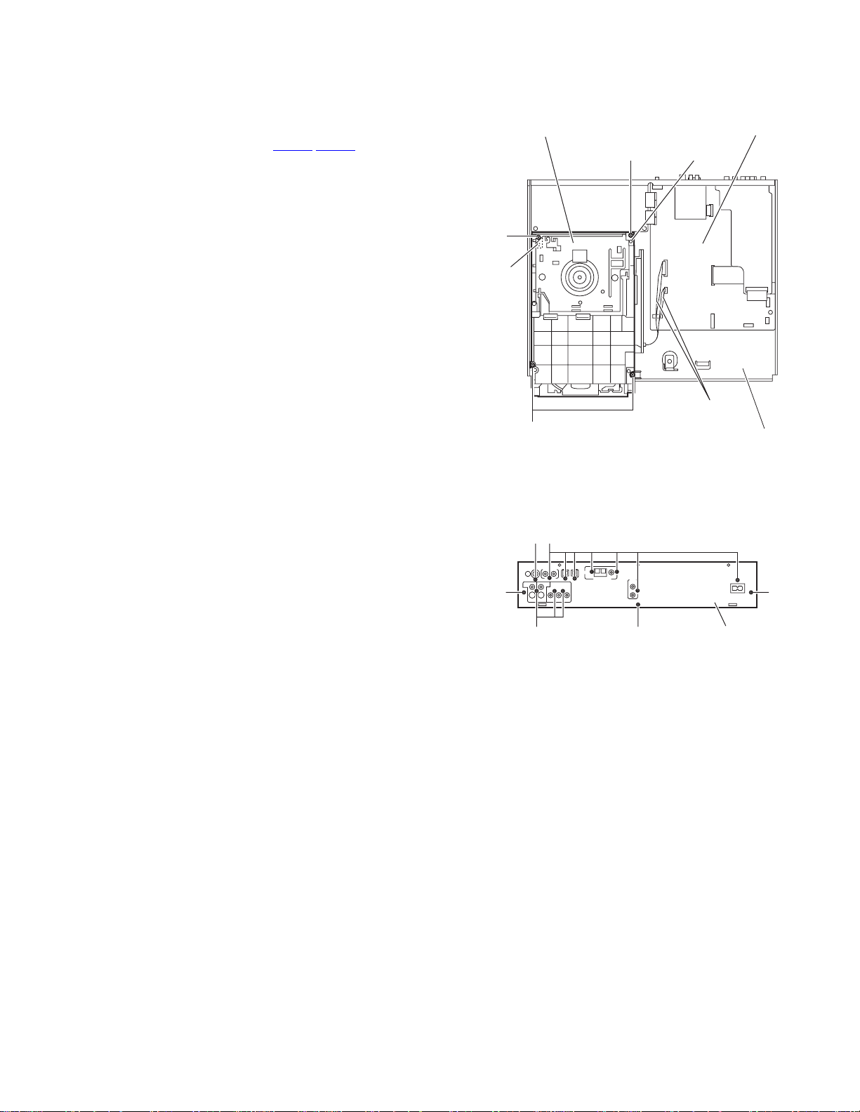
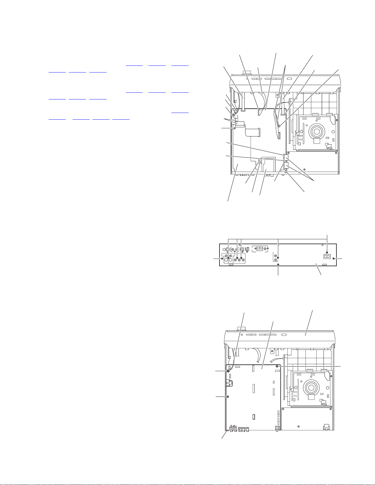
3.1.5 Removing the audio & digital input board
A
(See Figs.9 and 10)
• Prior to performing the following procedures, remove the metal
cover.
(1) From the top side of the main bod y, disconnect the card
wire from the connector CN401
board. (See Fig.9.)
(2) Remove the screw J attaching the audio & digital input
board. (See Fig.9.)
(3) From the back side of the main body, remove the screw K
and three screws L attaching the audio & digital input board
to the rear panel. (See Fig.10.)
(4) Take out the audio & digital input board from the main
body.
on the audio & digital input
Main board
CN401
CN402
CN416
N
Power supply board
3.1.6 Removing the tuner
(See Figs.9 and 10)
• Prior to performing the following procedures, remove the metal
cover.
(1) From the top side of the main bod y, disconnect the card
wire from the connector CN1
(2) From the back side of the main body, remove the two
screws M attaching the tuner to the rear panel. (See
Fig.10.)
(3) Take out the tuner from the main bod y.
3.1.7 Removing the power supply board
(See Figs.9 and 10)
• Prior to performing the following procedures, remove the metal
cover.
(1) From the top side of the main body, disconnect the parallel
wires from the connectors (CN416
the main board. (See Fig.9.)
(2) Remove the three screws N attaching the power supply
board. (See Fig.9.)
(3) From the back side of the mai n body, re mo ve the screw P
attaching the power supply board to the rear panel. (See
Fig.10.)
(4) Take out the power supply board from the main body.
Reference:
Remove the rear panel as required. (See Fig.8.)
on the tuner. (See Fig.9.)
,CN402 to CN404) on
J
Card
wires
CN1 CN403
Tuner
udio & Digital input board
CN404
Fig.9
KL M P
Fig.10
N
Parallel wires
Rear panel
1-10 (No.MB112)
Page 11
3.1.8 Removing the main board
(See Figs.11 to 13)
• Prior to performing the following procedures, remove the metal
cover.
(1) From the top side of the main bo dy, disconnect the card
wires from the connectors (CN405
, CN413, CN415) on the main board. (See Fig.11.)
CN411
[US/UW/UG version]
(2) From the top side of the main bo dy, disconnect the card
wires from the connectors (CN405
CN411, CN412, CN415) on the main board. (See Fig.11.)
[UJ version]
(3) Disconnect the parallel wires from the connectors (CN416
CN402 to CN404, CN408, CN409) on the main board. (See
Fig.11.)
(4) Remove the screw Q attaching the audio & dig ital input
board. (See Fig.11.)
(5) From the back side of the main body, remove the five
screws R and three screws S attaching the rear panel. (See
Fig.12.)
(6) Take out the rear panel together the audio & digital input
board and tuner.
(7) From the top side of the main body, re move the screw T
and two screws U attaching the main board to the bottom
chassis. (See Fig.13.)
Note:
When attaching the screw T, attach the earth wire of the front
panel assembly at the same time.
, CN407, CN410,
, CN407, CN410,
,
CN407
Parallel wire
Card wire
CN413
CN412
Card
wires
Q
CN416
CN402
Audio & Digital input board
Card wire
CN409
CN410
Card wire
CN411
Tuner
Main board
Card wires
CN405
CN403
Fig.11
Parallel wire
CN408
Parallel wires
CN404
CN415
S
T
U
Earth wire
S
Fig.12
Main board
R
S
Rear panel
Front panel assembly
U
Bottom chassis
Fig.13
(No.MB112)1-11
Page 12
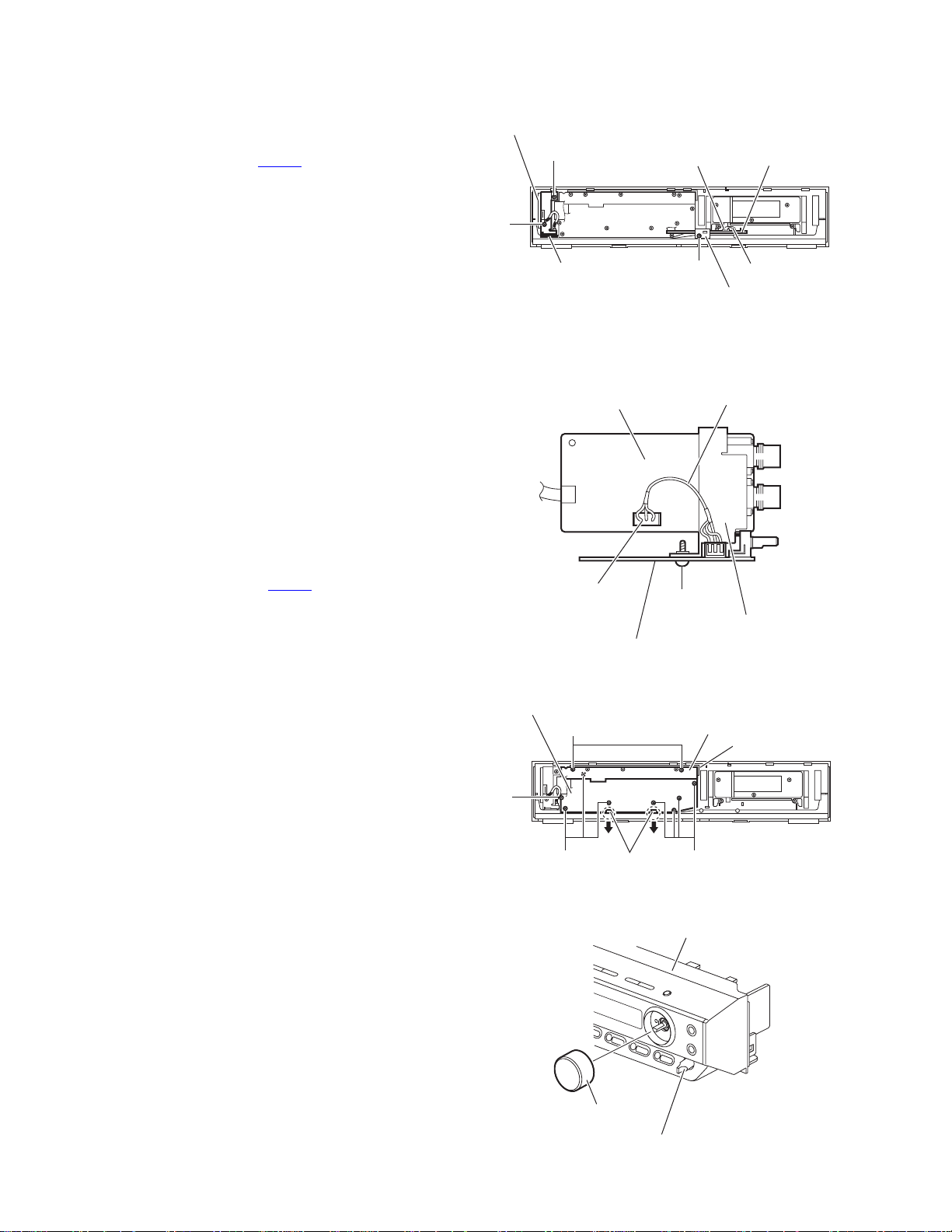
3.1.9 Removing the connect board
(See Fig.14)
• Prior to performing the following procedures, remove the metal
cover and front panel assembly.
(1) From the inside of the front panel assembly, disconnect the
card wire from the connector CN561
(2) Remove the screw V attaching the support board.
(3) Take out the connect board.
on the connect board.
Phone jack board
W
W
CN561 Connect board
3.1.10 Removing the phone jack board and microphone volume board
(See Figs.14,15 and 17)
• Prior to performing the following procedures, remove the metal
cover and front panel assembly.
(1) From the front side of the front panel assembly, pull out the
microphone volume knob. (See Fig.17.) [US/UW/UG
version]
(2) From the inside of the front panel assembly, remove the
two screws W attaching the phone jack board. (See
Fig.14.)
(3) Take out the phone jack board together the microphone
volume board. [US/UW/UG version]
(4) Take out the phone jack board. [UJ version]
(5) From the forward side of the phone jack board, disconnect
the wire from the connector CN702
board. (See Fig.15.) [US/UW/UG version]
(6) From the reverse side of the microphone boa rd, remove
the screw X attaching the microphone board to the brack-
et(H.phone) on the phone jack board. (See Fig.15.) [US/
UW/UG version]
3.1.11 Removing the operation board
(See Fig.16)
• Prior to performing the following procedures, remove the metal
cover and front panel assembly.
(1) Remove the two screws Y attaching the operation board.
(2) Take out the operation board together the button(top).
Reference:
Remove the button(top) from the front board as required.
on the phone jack
Front board
Z
Microphone volume board
Fig.14
Phone jack board
CN702
Microphone volume board
Fig.15
Y
ZZ
Claws e
Card wire
V
Support board
Wire
X
Bracket (H.phone)
Operation board
Button(top)
3.1.12 Removing the front board
(See Figs.16 and 17)
• Prior to performing the following procedures, remove the metal
cover, front panel assembly and connect board and operation
board.
(1) From the front side of the front panel assembly, pull out the
volume knob. (See Fig.17.)
(2) From the inside of the front panel assembly, remove the
eight screws Z attaching the front board. (See Fig.16.)
(3) Take out the front board while releasing the claws e in the
direction of the arrow. (See Fig.16.)
1-12 (No.MB112)
Fig.16
Front panel assembly
Volme knob
Microphone volume knob
Fig.17
Page 13
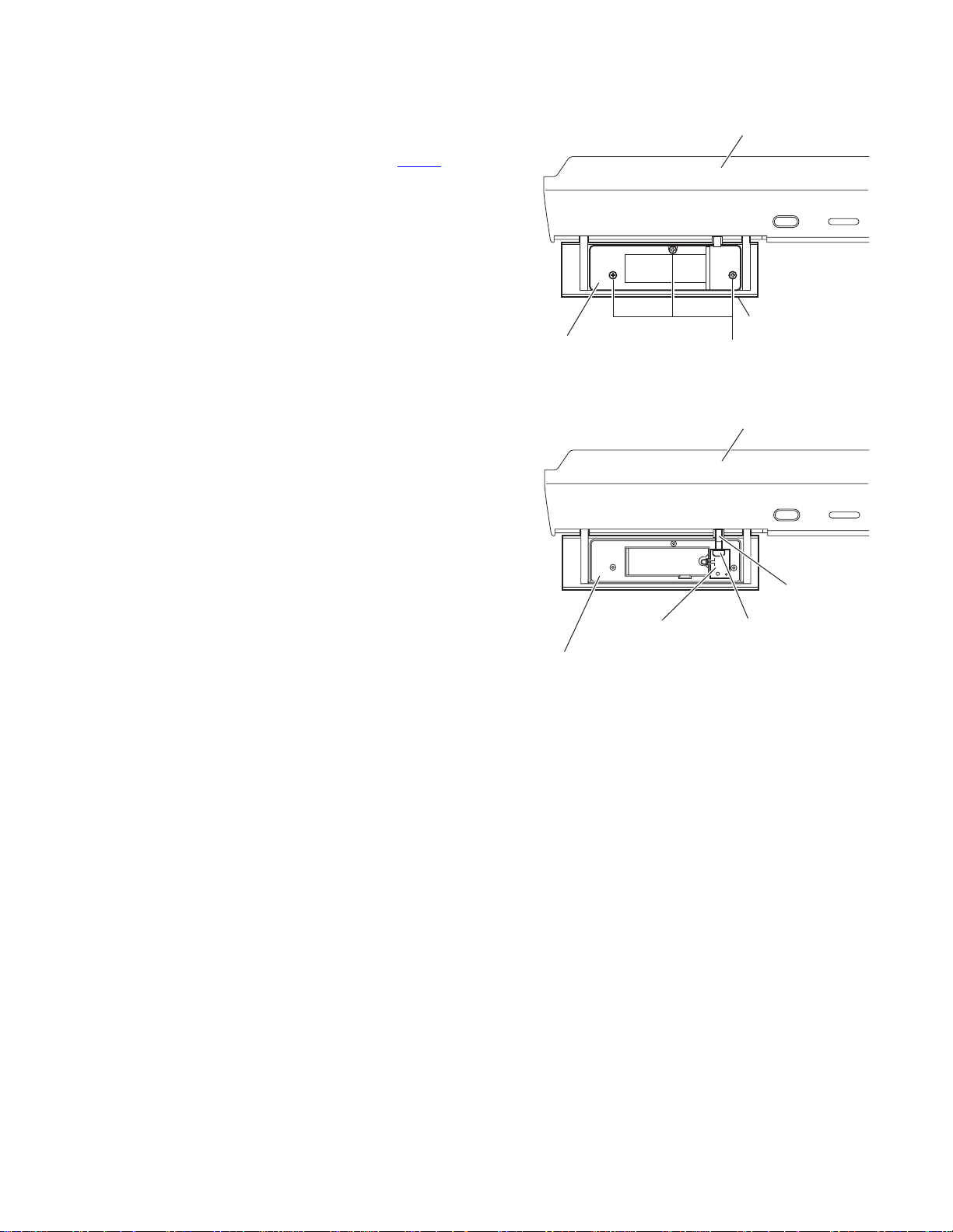
3.1.13 Removing the illumination board
(See Figs.18 and 19)
(1) Open the door assembly of the front panel assembly and
remove the three screws AA attaching the door cover to
the door assembly. (See Fig.18.)
(2) Disconnect the card wire from the connector CN551
illumination board. (See Fig.19.)
(3) Take out the illumination board from the door assembly.
on the
Front panel assembly
Door assembly
Door cover
AA
Fig.18
Front panel assembly
Illumination board CN551
Door assembly
Card wire
Fig.19
(No.MB112)1-13
Page 14

3.2 DVD changer mechanism assembly section
r
r
3.2.1 Removing the tray assemblies
(See Figs.1 to 5)
(1) Remove the two screws A from the top cover and release
the two joints a on the both sides of the DVD changer
mechanism assembly. (See Figs.1 and 2.)
(2) Remove the two rods from the top cover and remove the
top cover from the lifter assembly. (See Figs.1 and 2.)
(3) Remove the open det lever on the left side of the DVD
changer mechanism assembly. (See Fig.3.)
(4) From the right side of the DVD changer mechanism as-
sembly, draw out the tray assemblies toward the front while
pushing the part b of the side (R) assembly. (See Fig.4.)
Attention:
The tray can be locked if all tray assemblies are attached.
(5) From the topside of the DVD changer mechanism assem-
bly, move the stopper tabs c in the direction of the arrow
and release them. Pull out the tray assemblies from the
DVD changer mechanism assembly. (See Figs.4 and 5.)
Caution:
Remove the tray assembly from top tray 5 in order.
Attention:
When reattaching the tray assembly, or when removing the
disc remaining inside, refer to another section "3.2.15 T aking
out the disc in the play mode (See Fig.39 to 42)".
Top cover
Open det leve
Fig.3
c
A
a
Lifter assembly
a
Fig.1
Rods
A
a
Rods
Top cove
Tray assembly
c
b
Fig.4
Tray assembly
Side (R) assembly
Lifter assembly
1-14 (No.MB112)
a
Fig.5
Fig.2
Page 15

3.2.2 Removing the DVD servo boa rd
(See Figs.6 and 7)
• Prior to performing the following procedures, remove the tray
assemblies.
(1) From the topside of the DVD chang er mechanism assem-
bly, solder the short-circuit points d on the DVD pick up.
(See Fig.6.)
Caution:
Solder the short-circuit points d on the DVD pickup before disconnecting the flexible wire extending from the
DVD pickup. If you do not follow this instruction, the DVD
pickup may be damaged.
(2) From the right side of th e DVD changer mechanism as-
sembly, disconnect the card wires from the connectors
(CN103
(CN104
CN101
(3) Remove the screw B attaching the bracket to the DVD
changer mechanism assembly. (See Fig.7.)
(4) Release the two sections e of the bracket from the DVD
changer mechanism assembly and remove the DVD servo
board with the bracket. (See Fig.7.)
(5) Remove the two screws C attaching the DVD servo board
to the bracket. (See Fig.7.)
(6) Release the three sections f of the bracket and remove the
DVD servo board. (See Fig.7.)
Caution:
Unsolder the solders from the short-circuit points d after reassembling.
, CN201) and the wires from the connectors
, CN205) and the flexible wire from the connector
on the DVD servo board. (See Fig.7.)
Short circuit points d
DVD changer mechanism assembly
Fig.6
DVD changer mechanism assembly
C
f
DVD servo board
CN104
CN105
CN103 CN101
DVD pickup
C
f
CN201
3.2.3 Removing the switch board
(See Fig.8)
(1) From the bottom side of the DVD changer mech anism as-
sembly, disconnect the wires from connectors CN104
on the DVD servo board.
CN105
(2) Remove the screw D attaching the switch board to the DVD
changer mechanism assembly.
(3) Release the wires from the slots g of the switch board.
Caution:
When reassembling, let the wires through the slots g of the
switch board.
Reference:
When connecting the wires to the connectors on the DVD servo board, fix the wires with spacer.
and
B
Card wireBracket
DVD servo board
CN104 CN105 Wires Spacer
g
Switch board
Wires Flexible wire
Fig.7
g
D
Fig.8
DVD changer
mechanism assembly
Card wire
e
(No.MB112)1-15
Page 16

3.2.4 Removing the motor board
(See Figs.9 and 10)
(1) From the top side of the DVD chnager mechanism assem-
bly, remove the two belts from the motor pulleys. (See
Fig.9.)
Caution:
Take care not to attach grease on the belt.
(2) Remove the four screws E attaching the motors to the
chassis assembly. (See Fig.9.)
(3) From the bottom side of the DVD changer mechanism as-
sembly, remove the two screws F. (See Fig.10.)
(4) Disconnect the connector CN2
tray switch board and remove the motor board. (See
Fig.10.)
(5) Disconnect the card wire from the connector CN1
motor board. (See Fig.10.)
Caution:
• When connecting the card wire, let the card wire through the
slots h of the motor board. (See Fig.10.)
• When reattaching the motor, turn the side where th e label
should be put to the front side. (See Fig.10.)
Reference:
• You need not to remove the tray assemblies, a nd in such
case, move it.
• After connecting the motor board, attach the spacer on the
motor board. (See Fig.10.)
on the motor board from the
on the
E
Motor Motor
Motor pulleys
Labels
BeltBelt
E
Chassis assembly
Fig.9
Motors
Motor board
3.2.5 Removing the motor
(See Fig. 10)
• Prior to performing the following procedures, remove the motor
board.
(1) From the reverse side of the motor board, unsolder the four
soldered sections i on the motor board.
(2) From the forward side of the motor board, remove the mo-
tors.
Soldered sections i
Spacer
F
CN2
CN1
h
DVD changer mechanism assembly
Motors
Fig.10
Motor board
F
Card wire
1-16 (No.MB112)
Page 17

3.2.6 Removing the DVD traverse mechanism assembly
(See Figs.6 and 11)
• Prior to performing the following procedures, remove the tray
assemblies.
(1) From the topside of the DVD chang er mechanism assem-
bly, solder the short-circuit points d on the DVD pick up.
(See Fig.6.)
Caution:
Solder the short-circuit points d on the DVD pickup before disconnecting the flexible wire extending from the
DVD pickup. If you do not follow this instruction, the DVD
pickup may be damaged.
(2) From the bottom side of the DVD changer mech anism as-
sembly, disconnect the flexible wire from the connector
on the DVD servo board. (See Fig.11.)
CN101
(3) Disconnect the card wire from the connector CN201
DVD servo board. (See Fig.11.)
(4) Remove the three screws G attaching the DVD traverse
mechanism assembly. (See Fig.11.)
(5) Take out the DVD traverse mechanism assembly from the
DVD changer mechanism assembly.
Caution:
Unsolder the solders from the short-circuit points d after reassembling.
Reference:
When connecting the each wire to the connectors on the DVD
servo board, fix the each wire with spacers.
on the
DVD changer mechanism assembly
DVD servo board
G
Flexible wire Card wire
DVD traverse mechanism assembly
G
Fig.11
Spacers
CN101
CN201
(No.MB112)1-17
Page 18

3.2.7 Removing the DVD pickup
r
(See Figs.12 to 14)
• Prior to performing the following procedures, remove the tray
assemblies and DVD traverse mechanism assembly.
(1) From topside of the DVD tra verse mechanism assembly,
disconnect the flexible wire from the connector on the DVD
pickup. (See Fig.12.)
(2) Turn the screw shaft gear in the direction of the arrow 1 to
move the DVD pickup in the direction of the arrow 2. (See
Fig.12.)
(3) Remove the screw H attaching the gear holder. (See
Fig.12.)
(4) Remove the screw J attaching the SS adj. spring. (See
Fig.12.)
(5) Move the DVD pickup in the dire ction of the arrow and re-
move the screw shaft from the section j on the screw shaft
holder. (See Fig.13.)
(6) Remove the section k of the DVD pickup from the guide
shaft. (See Fig.13.)
(7) Remove the two screws K attaching the rack arm to the
DVD pickup. (See Fig.14.)
(8) Pull the screw shaft from the DVD pickup in the direction of
the arrow. (See Fig.14.)
3.2.8 Attaching the DVD pickup
(See Figs.12 to 14)
(1) Attach the screw shaft to the DVD pickup and attach the
rack arm with the screws K. (See Fig.14.)
Reference:
After attaching the screw shaft to the DVD pickup, attach
the screw shaft collar to the screw shaft. (See Fig.14.)
(2) Attach the section k of the DVD pickup to the guide shaft
first and attach the screw shaft to the section j on the screw
shaft holder. (See Fig.14.)
(3) Attach the SS adj. spring and gear holder with the screws
H and J. (See Fig.12.)
(4) Turn the screw shaft gear to move th e DVD pickup toward
the left. (See Fig.12.)
(5) Connect the flexible wire to the connector on the DVD pick-
up. (See Fig.12.)
DVD traverse mechanism assembly
Connector
Screw shaft
gear
1
Gear holder DVD pickup
Fig.12
DVD pickup Guide shaft
Screw shaft Screw shaft holder
Fig.13
DVD pickup
Flexible wire
2
SS adj. spring
JH
k
j
1-18 (No.MB112)
Rack arm
Screw shaft colla
K
Screw shaft
Fig.14
Page 19

3.2.9 Removing the spindle motor board
(See Figs.15 and 16)
• Prior to performing the following procedures, remove the tray
assemblies and DVD traverse mechanism assembly.
(1) From the topside of the DVD traverse mechanism assem-
bly, remove the four screws L attaching the DVD traverse
mechanism assembly to the DVD traverse mechanism
base. (See Fig.15.)
(2) Remove the wires from the solered section m on the spin-
dle motor board. (See Fig.15.)
(3) Remove the screw M attaching the spindle motor board.
(See Fig.15.)
(4) From the bottom side of the DVD traverse mechanism as-
sembly, remove the three screws N attaching the spindle
motor board. (See Fig.16.)
Reference:
When attaching the spindle motor board, let the card wire
through the hole n on the motor base. (See Fig.15.)
n
M
m
Wires
Card wire
L
L
DVD traverse mechanism assembly
Motor base
Spindle motor board
DVD traverse mechanism base
Fig.15
N
L
3.2.10 Removing the feed moter
(See Figs.17 and 18)
• Prior to performing the following procedures, remove the tray
assemblies, DVD traverse mechanism assembly, DVD pickup
and spindle motor board.
• Remove the wires of the feed motor as required.
(1) Remove the middle gear in the direction of the arrow. (See
Fig.17.)
(2) Remove the screw P and screw Q attaching the motor
base.
(3) Remove the screw R attaching the feed motor to the motor
base. (See Fig.18.)
(4) Take out the feed motor from the motor base.
Reference:
After attaching the feed motor, let the wires through the sections p and q on the motor base. (See Fig.17.)
Motor base
Middle
gear
Fig.16
Feed motor
P
qp
Q
Traverse mechanism chassis
Fig.17
Feed motor
Motor base
R
Fig.18
(No.MB112)1-19
Page 20

3.2.11 Removing the side (L) assembly and tray switch board
(See Figs.19 to 21)
• Prior to performing the following procedures, remove the tray
assemblies.
(1) From the topside of the DVD changer mechanism assem-
bly, remove the two screws S attaching the side (L) assembly. (See Fig.19.)
(2) From the left side of the DVD changer mechanism assem-
bly, removing the spacer fixing the tray switch board and
motor board. (See Fig.20.)
(3) Disconnect the connector CN3
from the motor board and detach the side (L) assembly in
an upward direction. (See Fig.20 .)
(4) Remove the screw T attaching the tray switch board to the
side (L) assembly. (See Fig.21.)
(5) Release the joint tab r of the side (L) assembly in the direc-
tion of the arrow 1 and release the joint tab s while removing the tray switch board in the direction of the arrow 2.
(See Fig.21.)
Reference:
After attaching the tray switch board to the motor board, fix
them with spacers.
on the tray switch board
Side (L) assembly
S
S
Fig.19
S
Side (L) assembly
Side (L) assembly
S
CN3
Spacer
Side (L) assembly
Motor board
Fig.20
r
1
1-20 (No.MB112)
2
s
Tray switch board
T
Fig.21
Page 21

3.2.12 Removing the side (R) assembly
(See Fig.22 to 26)
• Prior to performing the following procedures, remove the tray
assemblies and DVD servo board.
• When removing the DVD servo board, it is not necessary to re-
move the DVD servo board from the bracket.
(1) From the inside of the side (R) assembly, release the two
tabs t of the gear cover and remove the gear cover outward. (See Figs.22 and 23.)
(2) From the right side of th e DVD changer mechanism as-
sembly, remove the elevator spring attached to the hook u
of the chassis assembly. (See Figs.23 and 24.)
(3) From the topside of the DVD chang er mechanism assem-
bly, turn the gear 1 clockwise to move the elevator cam
rearward. (See Fig.24.)
(4) Move the two slots v and joint w of the elevator cam and
remove the elevator cam outward. (See Fig.24.)
(5) Remove the three screws U and d etach the side (R) as-
sembly upward. (See Figs.25 and 26.)
Caution:
When reattaching the side (R) assembly, make sure to fit the
shaft (part x) into the slot of the select lever. (See Fig.25.)
Side (R) assembly
t
U
Elevator spring
vv
w
Fig.24
u
Elevator cam
U
Select lever
x
Side (R) assembly
Gear cover
Elevator cam
Fig.22
Elevator spring
U
Side (R) assembly
Fig.25
Gear 1
U
u
U
Chassis assembly
Fig.23
Side (R) assembly
Fig.26
(No.MB112)1-21
Page 22

3.2.13 Removing the lifter assembly
(See Figs.27 to 31)
• Prior to performing the following procedures, remove the tray
assembies, DVD servo board, side (L) assembly and side (R)
assembly.
• When removing the DVD servo board, it is not necessary to re-
move the DVD servo board from the bracket.
(1) From the topside of the DVD changer mechanism assem-
bly, turn the gear 1 clockwise to move the lifter assembly
upward. (See Figs.27 and 28.)
(2) Turn the gear 2 clockwise to move the hook toward the
front until it stops. (See Figs.27 and 28.)
(3) Move the hook stopper in the direction of the arrow 2 while
pushing the tab y of the hook stopper to unlock it in the direction of the arrow 1 and release four joints z to detach
from the rack holder. (See Fig.29.)
(4) Release the rod from part aa. (See Fig.29.)
(5) Turn the gear 1 clockwise again to move the lifter assembly
upward. (See Fig.30.)
(6) Remove the lifter assembly from the DVD changer mecha-
nism assembly upward at the positions ab where the four
pins on the both sides of the lifter assembly fit to the notch-
es of the chassis assembly. (See Fig.30.)
(7) Move the lifter assemb ly in the direction of the arrow and
release it from the hook. (See Fig.31.)
Hook stopper
Gear 2
Gear 1
z
Rack holder
Hook
aa
z
z
1
Rod (L)
2
y
z
Hook stopper
Fig.29
Lifter assembly
ab
ab
Gear 1
Hook
Gear 2
Lifter assembly
Fig.27
Gear 1
Lifter assembly
Chassis assembly
Lifter assembly
Fig.30
ab
ab
Hook stopper
1-22 (No.MB112)
Hook
Fig.31
Hook
Fig.28
Page 23

3.2.14 Removing the rack holder assembly and sensor assembly
(See Figs.32 to 38)
• Prior to performing the following procedures, remove the tray
assemblies, side (L) assembly, side (R) assembly and lifter assembly.
Reference:
If the slide gear of the DVD changer mechanism assembly
places at joint ac of the rack holder assembly, turn the gear 1
counterclockwise to move the slide gear in the direction of the
arrow. Then Remove the rack holder assembly. (See Figs.32
and 33.)
(1) Remove the three screws V attachin g the rack holder as-
sembly and release joint ac from the notch ad. (See
Figs.32 and 34.)
Caution:
When reattaching the rack holder assembly, do not nip
the wires extending from the sensor assembly. (See
Fig.32.)
(2) Remove the two screws W attaching the sensor assembly.
(See Figs.35 and 38.)
(3) Move the sensor assembly in the direction of the arrow to
release from the joint section ae. (See Figs.35 and 38.)
(4) Remove the sensor spring attached to the bottom of the
sensor assembly from the boss af on the sensor slider.
(See Figs.35 and 36.)
(5) Remove the screw X and Y attaching the sensor board and
SV. resister respectively. (See Fig.37.)
Reference:
Remove the soldered section ai on the sensor board as required. (See Fig.37.)
Caution:
• When reattaching the SV. resister, attach the sensor slider
to the sensor bracket and fit the lever on the bottom of the
SV. resister into slot aj of the sensor slider. (See Figs.36 and
37.)
• When reattaching the rack holder assembly, turn the gear 1
clockwise to move the slide gear and slide lever inside the
body in the direction of the arrow. (See Figs.32 and 38.)
• Let the wire extending from the sensor assembly through
notch ag to the bottom of the DVD changer mechanism assembly. (See Figs.35 and 38.)
• Fit pin ak of the slide lever into hole ah of the sensor slider
on the bottom of the sensor assembly while attaching the
sensor spring to the boss af of the sensor slider. (See
Figs.36 and 38.)
• Joint section ae of the sensor assembly to the notch am of
the DVD changer mechanism assembly. (See Figs.35 and
38.)
V
Slide gear
Slide gear
Rack holder assembly
V
ac
Wires
V
Fig.32
Rack holder assembly
ac
Fig.33
Gear 1
(No.MB112)1-23
Page 24

Rack holder assembly
r
XY
Sensor board
W
ad
Fig.34
ac
ag
Sensor assembly
Sensor slide
SV resister
aj
Slide gear
ai
Sensor bracket
Sensor slider
Fig.37
W
Sensor assembly
W
ae
ah
W
af
Sensor slider
af
ae
Fig.35
aj
Sensor spring
ah
af
am
ak
Sensor spring
Fig.38
ag
Slide lever
1-24 (No.MB112)
Sensor spring
Fig.36
Page 25

3.2.15 Taking out the disc in the play mode
r
(See Fig.39 to 42)
Reference:
Refer to "Removing the tray assemblies".
(1) From the topside of the DVD mechanism assembly, re-
move the top cover.
(2) Unlock the tray assemblies and draw out the tray assem-
blies toward the front.
(3) From the top side of the DVD mechanism a ssembly, turn
the gear 1 clockwise to move the lifter assembly upward.
(See Fig.39.)
(4) Turn the gear 2 clockwise to move the sub tray re maining
inside the lifter assembly toward the front, then pull out.
(See Fig.39.)
(5) Take out the disc on the sub tray. (See Fig.40.)
(6) After clearing away the disc, insert the sub tray into the
main tray. (See Fig.41.)
Caution:
When reattaching the sub tray, move the tray stopper on
the bottom of the main tray in the direction of the arrow
to lock the sub tray certainly. (See Figs.41 and 42.)
(7) Push the tray assembly toward the body and reattach.
Tray assemblies
Tray assembly
Tray stopper
Disc
Sub tray
Fig.40
Main tray
Gear 2
Gear 1
Sub tray
Sub tray
Fig.41
Tray stoope
Fig.39
Fig.42
(No.MB112)1-25
Page 26

3.3 Speaker section
A
3.3.1 Removing the amplifier assembly
(See Figs.1 and 2)
(1) From the rear side of the sp eaker main b ody, re move four
screws A attaching the heat sink cover. (See Fig.1.)
(2) Remove the nine screws B attaching amplifier assembly.
(See Fig.2.)
(3) Move the amplifier assembly backward and disconnect the
wire from connector CN402
assembly. (See Fig.2.)
in the lower part of the amplifier
A
Amplifier
assembly
Heat sink
cover
A
Fig.1
mplifier
assembly
B
B
CN402
Fig.2
B
1-26 (No.MB112)
Page 27

3.3.2 Removing the rear p anel
(See Fig.3)
• Prior to performing the following procedures, remove the
amplifier assembly.
(1) Remove the four screws C, twelve screws D and screw E
attaching the rear panel.
(2) Take out the rear panel from the amplifier assembly.
D
E
Rear panel
C
D
D
3.3.3 Removin g the SP terminal board
(See Figs.4 and 5)
• Prior to performing the following procedures, remove the
amplifier assembly and rear panel.
(1) From the top side of the amplifier assembly, disconnect the
card wires from the connectors CN101
mother board (See Figs.4 and 5.)
(2) Disconnect the connectors CN401, CN403 and CN404 on
the SP terminal board from the connectors CN501
and CN504 on the mother board while lifting the SP
terminal board upward. (See Fig.5.)
(3) Take out the SP terminal board from the amplifier
assembly.
Reference:
When attaching the SP terminal board, insert the SP terminal
board in the section a of the barrier.
and CN102 on the
, CN503
C
D
C
Mother
board
SP terminal
board
CN101
CN102
Tie band
Section a
Amplifier
assembly
C
D
Fig.3
CN101
CN102
Tie band
Fig.4
CN401
CN403
CN404
Fig.5
Amplifier
assembly
CN501
CN503
CN504
Mother
board
SP terminal
board
(No.MB112)1-27
Page 28

3.3.4 Removing the mother board assembly
(See Fig.6)
• Prior to performing the following procedures, remove the
amplifier assembly, rear panel and SP terminal board.
(1) From the top side of the amplifier assembly, disconnect the
card wires from the connectors CN151
board.
(2) From the top side of the amplifier assembly, remove the
five screws F attaching the mother board.
(3) Take out the mother board assembly from the amplifier
assembly.
3.3.5 Removing the mother board
(See Fig.7)
• Prior to performing the following procedures, remove the
amplifier assembly, rear panel, SP terminal board and mother
board assembly.
(1) From the bottom side of the mother board, remove the two
screws G and two screws H attaching the mother board.
(2) Disconnect the connectors CN521
CN532 on the mother board while lifting the mother board
upward, and take out the mother board.
on the mother
, CN522, CN531 and
Mother
board
F
CN151
CN522
G
Fig.6
H
F
Amplifier
assembly
Mother board
CN531
CN521
G
CN532
H
Fig.7
1-28 (No.MB112)
Page 29

3.3.6 Removing the power amplifier b oard (A)
(See Figs.8 and 9)
• Prior to performing the following procedures, remove the
amplifier assembly, rear panel, SP terminal board, mother
board assembly and mother board.
(1) Remove the three screws J attaching the heat sink to the
power amplifier board (A). (See Fig.8.)
(2) From the bottom side of the power amplifier board (A),
disengage the four sections b of the engagement. (See
Fig.9.)
(3) From the top side of the power amplifier board (A),
disengage the section c of the engagement to the direction
of the arrow. (See Fig.9.)
(4) Remove the power amplifier board (A) from the P.TR
holder (A).
3.3.7 Removing the power amplifier b oard (B)
(See Figs.8 and 10)
• Prior to performing the following procedures, remove the
amplifier assembly, rear panel, SP terminal board, mother
board assembly and mother board.
(1) Remove the three screws K attaching the heat sink to the
power amplifier board (B). (See Fig.8.)
(2) From the bottom side of the power amplifier board (B),
disengage the four sections c of the engagement. (See
Fig.9.)
(3) From the top side of the power amplifier board (B),
disengage the section d of the engagement to the direction
of the arrow. (See Fig.9.)
(4) Remove the power amplifier board (B) from the P.TR
holder (B).
J
Power
amplifier
board (A)
1
2
(Bottom side)
Power amplifier
board (A)
2
1
P.TR holder (A)
P.TR holder (B)
Fig.8
Sections b
CN251
CN252
K
Power
amplifier
board (B)
K
Heat sink
P.TR holder (A)
Section c
(Bottom side)
Section e
P.TR holder (B)
Sections b
Fig.9
Sections d
CN351
CN352
Sections d
Fig.10
1
2
(Bottom side)
Power amplifier
board (B)
2
1
(Bottom side)
(No.MB112)1-29
Page 30

3.3.8 Removing the power tr ansformer
r
A
L
(See Fig.11)
• Prior to performing the following procedures, remove the
amplifier assembly, rear panel, SP terminal board and mother
board assembly.
(1) Remove the tie band, and remove the four screws L
attaching the power transformer.
(2) Take out the power transformer from the amplifier
assembly.
3.3.9 Removing the speaker net
(See Figs.12 and 13)
(1) Insert the tip of a flat-bladed screwdriver or similar tool into
the space between the speaker main body and speaker
net, and lift the speaker net little by little to remove. (See
Figs.12 and 13.)
Note:
To prevent damaging the speaker net and speaker main
body, insert cushioning plates etc. to the section f and
below the tip of the flat-bladed screwdriver or similar tool.
(2) Take out the speaker net from the speaker main bod y.
L
Power
transforme
Tie band
C bracket
L
Fig.11
1-30 (No.MB112)
Speaker net
Section f
Speaker net
Speaker main body
Section f
Fig.12
Chshioning
blate,etc.
Fig.13
Speaker main body
Flat-bladed
screwdriver,etc.
Page 31

3.3.10 Removing the speaker
(See Figs.14 and 15)
(1) From right side of the speaker main body, remove the eight
screws M attaching the speaker. (See Fig.14)
(2) Take out the speaker from the speaker main body. (See
Fig.15.)
(3) Disconnect the wires from the terminal of the speaker. (See
Fig.15.)
M
Speaker
Speaker main body
M
Fig.14
Speaker main body
Terminal
Fig.15
Speaker
(No.MB112)1-31
Page 32

3.4 Satellite speaker section
A
• Before disassembling the main body, lay down it first.
3.4.1 Removing the cabinet assembly
(See Figs.1 and 2)
(1) From the bottom side of the main body, remove the four
screws A attaching the stand assembly. (See Fig.1.)
CAUTION:
The speaker wire assembly is connected with the
speaker terminals at this time. Be careful not to damage
the speaker terminal and the speaker wire.
(2) From the top side of the stand assembly, disconnect the
speaker wire assembly on the speaker terminals. (See
Fig.2.)
(3) Remove the seven hooks a attaching the net assembly to
the cabinet assembly. (See Fig.2.)
CAUTION:
When removing the net assembly, be careful not to
damage the speakers and the cabinet assembly.
Reference:
• As the net assembly is fixed with the adhesive and the
two-sided tape, remove the net assembly by using a
minus driver or similar tool.
• Attach the net assembly after applying the adhesive to
the hooks a.
(4) Remove the two screws B and screw C. (See Fig.2.)
(5) Pull out the stand from the cabinet assembly while peeling
off the adhesive section b. (See Fig.2.)
Hooks a
Net assembly
Hooks a
B
Hooks a
Cabinet assembly
C
Adhesive
section b
Stand
Fig.1
Stand assembly
Speaker wire assembly
Speaker terminal
Speaker terminal
A
Stand assembly
Fig.2
1-32 (No.MB112)
Page 33

3.4.2 Removing the Speakers
(See Fig.3)
• Remove the net assembly from the cabinet assembly. (See
Fig2.)
(1) Remove the eight screws D attaching the two speakers.
(2) Take out the two speakers from the cabinet assembly.
(3) From the back side of the speakers, disconnect the
speaker wires from the speaker terminals.
D
Cabinet assembly
Speaker terminal
Speaker
Speaker
wires
D
Speaker wires
Speaker
Speaker terminal
Fig.3
(No.MB112)1-33
Page 34

3.5 Center speaker section
3.5.1 Removing the Center Speakers
(See Fig.1)
(1) From the front side of the cabinet assembly, remove the six
hooks a attaching the net assembly.
CAUTION:
When removing the net assembly, be careful not to
damage the speakers and the cabinet assembly.
Reference:
• As the net assembly is fixed with the adhesive and the
two-sided tape, remove the net assembly by using a
minus driver or similar tool.
• Attach the net assembly after applying the adhesive to
the hooks c.
(2) Remove the eight screws A attaching the center speakers.
(3) Take out the center speakers from the cabinet assembly.
(4) From the back side of the center speakers, disconnect the
speaker wires on the speaker terminals.
Center speakers
Hooks a
Hooks a
Net assembly
Cabinet assembly
Speaker wires
A
A
Speaker wires
Speaker terminal
Hooks a
Fig.1
1-34 (No.MB112)
Page 35

SECTION 4
r
ADJUSTMENT
4.1 Test mode setting method
(1) Unplug the power plug.
(2) Insert power plug into outlet while pressing both "STOP" key and "OPEN/CLOSE" key (for DISC 1) of the main body.
(3) "Area code" is indicated at the upper left of display.
(4) To release test mode, press "STANDBY/ON" key of the main body.
NOTE:
Each pressing of "CHOICE" key of the remote controller in test mode changes the mode as follows.
TEST --------------
_ _ --------------FL Display becomes all lighting
CHECK -------------------------EXPERT -------------------------
4.2 Method of displaying version of firmware
(1) Set the main body at test mode.
(2) Press "CHOICE" key of the remote controller once. Then, version number and alphabetical letter of the system controller and
the back end are displayed in the FL display as follows.
Becomes test mode
Area code
FE microcomputer learning processing condition
Version of firmware (Refer to "3.2 Metod of displaying version firmware".)
Mechanism check mode
Front end check mode
FL Display (Example)
12_1a_02_3f
Back end (BE) micro compute
Front end (FE) micro computer
Mechanism micro computer
System micro computer
4.3 Initialization method
Please initialize according to the following procedures in the following case:
• Just after you upgrade the firmware.
• After you confirm the symptoms that a customer points out. First Initialize, and then confirm whether the symptoms are improved or
not.
• After servicing, before returning the main body to a customer. (Initialized main body should be returned to a customer.)
(1) Set the main body at test mode.
(2) Press "PAUSE" key of the main body.
(3) When initialization is completed, "30" and "RDS" is displayed in the FL display
CHOICE key
(switch of mode)
STOP key
(for test mode)
STANDBY/ON key
OPEN/CLOSE key
(for test mode)
PAUSE key
(for initialize)
FL display
(No.MB112)1-35
Page 36

4.4 All-initialization method
Please perform all-initialization according to the following procedures in the following case:
• Just after you exchange the pick-up.
• Just after you exchange the spindle motor.
• Just after you exchange the traverse mechanism base.
NOTE:
Please perform all-initialization when you exchange the parts above and also when you remove the parts above.
• Just after the flap adjustment of the pick-up guide shaft.
(1) Set the main body at test mode.
(2) Press and hold "REVERSE SKIP" key of the main body for more than 1.5 seconds.
(3) When all-initialization is completed, "33" and "RDS" is displayed in the FL display.
(4) To release test mode, press "STANDBY/ON" key of the main body
NOTE:
After all-initialization, be sure to perform optimization adjustment of Front End parameter.
4.5 Optimization adjustment of Front End parameter
Adjustment to optimize Front End parameter must be performed in each mechanism assembly of this model for high-speed startin g.
Please perform optimization according to the following procedures just after all-initialization is completed and when FL display shows
anything except "0" (For example when FL display shows "1", "2", and "3") at test mode
(1) Press "STANDBY/ON" key of the main body to turn the main bod y on (not to set the main body at test mode).
(2) Insert the test disc VT-501 or commercial dual-layer DVD software.
(3) Remove the disc when the FL display changes from "READING" to disc information.
(4) Perform the same procedures as in (2) and (3) above by using the test disc CTS-1000 or commercial CD-DA software.
(5) Set the main body at test mode, and check that the FL display shows "0".
NOTE:
Status of this adjustment can be judged by the number displayed at test mode as follows:
DVD adjustment CD adjustment FL display at test mode
Adjusted Adjusted 0
Not adjusted Adjusted 1
Adjusted Not adjusted 2
Not adjusted Not adjusted 3
NOTE:
As for a disc used for adjustment,
• Disc should be mounted. ("Mounting" means to display "READING" after the disc is inserted and then display the disc information.) Disc need not be played.
• If you do not have test disc either VT-501 (DVD) or CTS-1000 (CD-DA), use a commercial disc (for DVD, dual-layer software) after seeing and checking that the disc is neither curved nor foreseen that it may shake at the time of playback. If you
use a disc with bad features, starting time may be slow or disc may not be read.
STOP key
(for test mode)
STANDBY/ON key
FL display
REVERSE SKIP key
(for all initialize : It pushes 1.5 seconds or more.)
OPEN/CLOSE key
(for test mode)
1-36 (No.MB112)
Page 37

4.6 Display of current value of laser
(1) Set the main body at test mode.
(2) Press "CHOICE" key of the remote controller three times. Then, FL display is displayed "CHECK".
(3) The laser current val ue can be switche d between the val ue of CD and that of DVD by pressing the fo llowing key of the remote
controller.
FL Display (Example)
1419 0000
Remote controller "4" key --- Laser of CD
Remote controller "5" key --- Laser of DVD
• The number shown in the FL display shows mA of current value of laser.
• The first two numbers ("14" in "1419") shows current value of laser at the time of adjustment a fter the latest all-initialization,
14mA in this example.
• The last two numbers ("19" in "1419") shows the present current value of laser, 19mA in this example.
• The first two numbers ("14" in "1419") usually shows current value of laser at the time of shipment, so you can see how the
product has been deteriorated by comparing the first two numbers ("14" in "1419") and the last two numbers ("19" in "1419").
CD and DVD:
The laser current value of 80mA or less in normal. The laser current value of over 81mA is not normal. Laser
diode of the pickup has been deteriorated.
• To return to test mode, press "STOP" key of the main body.
4.7 Flap adjustment of the pick-up guide shaft
Please perform flap adjustment of the pick-up guide shaft in the following case:
• Just after you exchange the pick-up.
• Just after you exchange the spindle motor.
• Just after you exchange the traverse mechanis m ba se .
NOTE:
Please perform flap adjustment of the pick-up guide shaft when you exchange the parts above and also w hen you remove the
parts above.
• When the reading accuracy of the signal is bad (The re is a block noise in the screen, Screen stops in the outer circumference of a
disc, etc.)
4 key
(laser of CD)
CHOICE key
(switch of mode)
5 key
(laser of DVD)
6 key
(display of jitter value)
STOP key
(for test mode)
STANDBY/ON key
OPEN/CLOSE key
(for test mode)
PLAY key
(for jitter value)
FL display
(No.MB112)1-37
Page 38

4.7.1 Tool for adjustment
F
b
*Stud: One set (four studs), Part number: JIGXVS40
4.7.2 Preparation for adjustment
(1) Set the disassembly procedure, and remove the changer mechanism assembly from the main body.
(2) Disconnect the card wires from the connectors CN501
(3) Attach the four studs to the changer mechanism assembly.
(4) Put the changer mechanism assembly in the main body, and connect the card wires to the connector CN501
DVD servo board.
Studs
and CN502 on the DVD servo board.
Changer mechanism assembly
CN501
CN502
DVD servo board
and CN502 on the
Stud
Changer mechanism assembly
4.7.3 Adjustment
(1) Set the unit to test mode.
(2) Press the "CHOICE" key of the remote controller three times, and the FL display is displaye d "CHECK".
(3) A "PLAY" key is pushed after insert a test disc (VT-501), and press the numeric key "1" of the remote controller for automat ic
adjustment.
(4) After a few seconds, press the numeric key "6" of the remote controller. Then, the FL display displays a jitter value.
(5) Turn the adjustment screws on the underside of the traverse mechanism with Phillips screw driver until the maximum jitter value
is displayed on the FL display. (In this model, a bigger jitter value means a better result.)
NOTE:
Reference values to judge whether the jitter is allowable or not are displayed, instead of actual jitter values.
Screw a
ront
Stud
Screw
To front panel assembly
POINT:
Turn the adjustment screws a and b to the same angle in the
right direction. And turn the adjustment screws a and b to the
same angle in the left direction. Then, turn the screws a and b
in either the right or the left direction to increase the number of
jitter. Don't turn the adjustment screw c.
FL Display (Example)
Main body
1162 1419
1-38 (No.MB112)
Jitter
Screw c
Page 39

4.8 Confirmation of region
(1) Unplug the power plug.
(2) Insert power plug into outlet while pressing both "PAUSE" key and "FORWARD SKIP" key of the main body.
About 3 seconds later, FL display indicates "REGION ".
(3) Push the "OPEN/CLOSE" key (for DISC 1) and confirm the tray of DISC 1 is ejected.
(4) To release test mode, press "STANDBY/ON" key of the main body.
NOTE:
Until the tray is completely close up and the sound of mechanism movement disappears, do not pull the power
plug from the outlet.
4.9 Upgrading of firmware
The latest firmware for upgrading is updated in "Optical disc CSG" page in JS-net. At the time of service, compare the version of the
product and the latest version, and upgrade the old version into the latest version.
(1) Press the "STANDBY/ON" key of the main body to turn the main body on.
(2) A disc button is pushed after inserting an upgrade disc in a tray 1.
(3) When FL display of the main body changes from "READING" to "UPGRADE", press "cursor UP" key ( ) of the remote controller.
(4) The entire screen becomes blue, and upgrading starts.
(5) The tray opens automatically. Remove the upgrade disc.
(6) The screen returns to the normal screen. Then, press the "STANDBY/ON" key of the main body. When the stand-by indicator is
lighted, upgrading is completed.
(7) Set the main body at test mode, and perform initialization. Then, confirm the version of the firmware.
Firmware upgrade Disc ... press UP
Upgrade application initializing...
Cursor UP key
(for firmware upgrade)
CHOICE key
(switch of mode)
While upgrading (blue screen)After inserting the up-grade disc
STOP key
(for test mode)
STANDBY/ON key
NO DISC
When up-grade is completed
PAUSE key
(for initialize and region)
FORWARD SKIP key
(for region)
FL display
OPEN/CLOSE key (for disc 1)
(No.MB112)1-39
Page 40

SECTION 5
TROUBLESHOOTING
This service manual does not describe TROUBLESHOOTING.
1-40 (No.MB112)
Page 41

(No.MB112)1-41
Page 42

VICTOR COMPANY OF JAPAN, LIMITED
AV & MULTIMEDIA COMPANY AUDIO/VIDEO SYSTEMS CATEGORY 10-1,1chome,Ohwatari-machi,Maebashi-city,371-8543,Japan
(No.MB112)
Printed in Japan
WPC
 Loading...