

Page 1
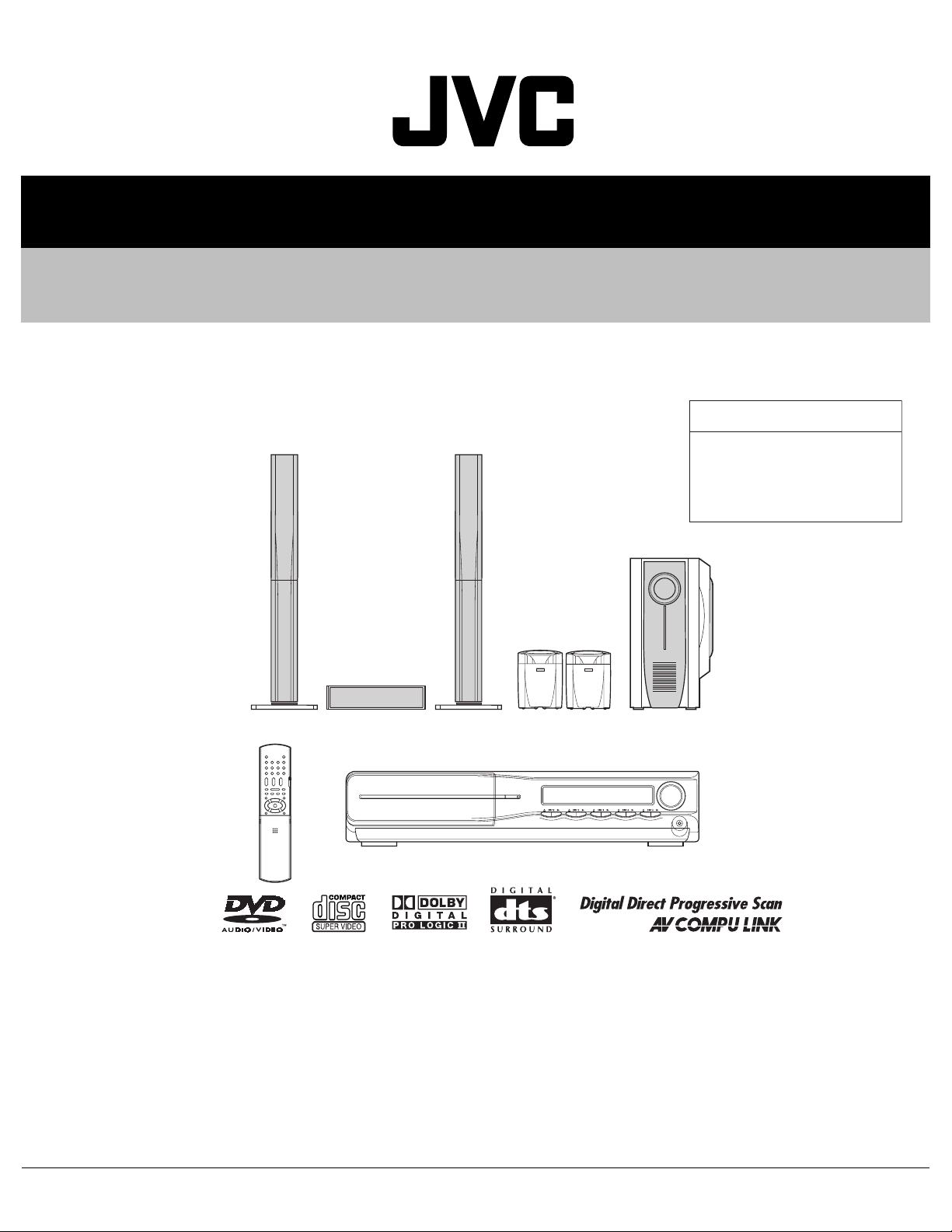
SERVICE MANUAL
DVD DIGITAL THEATER SYSTEM
MB36220054
TH-C5
TH-C5
Area suffix
J ---------------------------- U.S.A.
C ------------------------- Canada
(SP-THC5C) (SP-THC5S)
(SP-THC5F)(SP-THC5F)
(XV-THC5)
(SP-PWC5)
TABLE OF CONTENTS
1 PRECAUTION. . . . . . . . . . . . . . . . . . . . . . . . . . . . . . . . . . . . . . . . . . . . . . . . . . . . . . . . . . . . . . . . . . . . . . . . . 1-4
2 SPECIFIC SERVICE INSTRUCTIONS . . . . . . . . . . . . . . . . . . . . . . . . . . . . . . . . . . . . . . . . . . . . . . . . . . . . . . 1-7
3 DISASSEMBLY . . . . . . . . . . . . . . . . . . . . . . . . . . . . . . . . . . . . . . . . . . . . . . . . . . . . . . . . . . . . . . . . . . . . . . . 1-8
4 ADJUSTMENT . . . . . . . . . . . . . . . . . . . . . . . . . . . . . . . . . . . . . . . . . . . . . . . . . . . . . . . . . . . . . . . . . . . . . . . 1-37
5 TROUBLESHOOTING . . . . . . . . . . . . . . . . . . . . . . . . . . . . . . . . . . . . . . . . . . . . . . . . . . . . . . . . . . . . . . . . . 1-42
COPYRIGHT © 2005 Victor Company of Japan, Limited
No.MB362
2005/4
Page 2
SPECIFICATION
Center unit
Audio section Total Harmonic Distortion 0.02%*1
Digital input*2 DIGITAL IN(DBS):-21 dBm to -15 dBm(OPTICAL:660 nm ±30 nm)
Video section Video System NTSC
Horizontal Resolution 500 lines
Signal-to-Noise Ratio 64 dB
Video output level Composite:1.0 V(p-p)/75Ω
S-video-Y:1.0 V(p-p)/75 Ω
S-video-C:0.286 V(p-p)/75 Ω
Component-Y:1.0 V(p-p)/75 Ω
Component-PB/PR:0.7 V(p-p)/75 Ω
Video input sensitivity/Impedance (VCR IN) Composite:1.0 V(p-p)/75 Ω
S-video-Y:1.0 V(p-p)/75 Ω
S-video-C:0.286 V(p-p)/75 Ω
Tuner section Tuning Range FM:87.5 MHz to 108.0 MHz
AM:530 kHz to 1 710 kHz
General Power Requirements AC 120 V, 60 Hz
Power Consumption 16 W (at operation)
1.3 W (in standby mode)
Dimensions (W×H×D) 400 mm × 85 mm × 399 mm
(15-3/4 inches × 3-3/8 inches ×15-3/4 inches)
Mass 4.2 kg (9.3 lbs)
*1: This value is measured at System cord CONNECTOR for reference.
*2: Corresponding to Linear PCM, Dolby Digital, and DTS DigitalSurround (with sampling frequency -32 kHz, 44.1 kHz, 48 kHz)
Subwoofer (SP-PWC5)
Amplifier section Front/Center/Surround 167 W per channel, RMS at 3 Ω at 1kHz, with 10 % total harmonic distortion.
Subwoofer 167 W, RMS at 3 Ω at 100 Hz, with 10 % total harmonic distortion.
Speaker section Speaker unit 25 cm (9-7/8 inches) Bass-reflex
Power Handling Capacity 170 W
Impedance 3Ω
Frequency Range 25 Hz to 200 Hz
General Power Requirements AC 120 V , 60 Hz
Power Consumption 160 W (at operation)
0 W (in standby mode)
Dimensions (W × H × D) 264 mm × 481 mm ×459 mm
(10-7/16 inches × 18-15/16 inches × 18-1/8 inches)
Mass 16.5 kg (37 lbs)
1-2 (No.MB362)
Page 3
Satellite Speakers (SP-XTHC5)
Front speakers (SP-THC5F) Speaker unit 5.5 cm (2-3/16 inches) × 2
Bass-reflex, Magnetically Shielded
Power Handling Capacity 170 W
Impedance 3Ω
Frequency Range 95 Hz to 20 kHz
Dimensions (W × H ×D) 230 mm × 1 103.5 mm × 285 mm
(9-1/16 inches × 43-1/2 inches × 11-5/16 inches)
Mass: 3.5 kg (7.8 lbs) each
Center speaker (SP-THC5C) Speaker unit 5.5 cm (2-3/16 inches) × 2
Bass-reflex, Magnetically Shielded
Power Handling Capacity 170 W
Impedance 3Ω
Frequency Range 90 Hz to 20 kHz
Dimensions (W × H × D) 320 mm × 75 mm × 92 mm
(12-5/8 inches × 3 inches × 3-5/8 inches)
Mass 0.90 kg (2.0 lbs)
Surround speakers (SP-THC5S) Speaker unit 8.0 cm (3-3/16 inches)
Bass-reflex
Power Handling Capacity 170 W
Impedance 3Ω
Frequency Range 80 Hz to 20 kHz
Dimensions (W × H × D) 111.5 mm × 148 mm × 106.5 mm
(4-7/16 inches × 5-7/8 inches ×4-1/4 inches)
Mass 0.44 kg (0.97 lbs) each
Designs & specifications are subject to change without notice.
(No.MB362)1-3
Page 4
SECTION 1
PRECAUTION
1.1 Safety Precautions
(1) This design of this product contains special hardware and
many circuits and components specially for safety purposes. For continued protection, no changes should be made
to the original design unless authorized in writing by the
manufacturer. Replacement parts must be identical to
those used in the original circuits. Services should be performed by qualified personnel only.
(2) Alterations of the design or circuitry of the product should
not be made. Any design alterations of the product should
not be made. Any design alterations or additions will void
the manufacturers warranty and will further relieve the
manufacture of responsibility for personal injury or property
damage resulting therefrom.
(3) Many electrical and mechanical parts in the products have
special safety-related characteristics. These characteristics are often not evident from visual inspection nor can the
protection afforded by them necessarily be obtained by using replacement components rated for higher voltage, wattage, etc. Replacement parts which have these special
safety characteristics are identified in the Parts List of Service Manual. Electrical components having such features
are identified by shading on the schematics and by ( ) on
the Parts List in the Service Manual. The use of a substitute
replacement which does not have the same safety characteristics as the recommended replacement parts shown in
the Parts List of Service Manual may create shock, fire, or
other hazards.
(4) The leads in the products are routed and dressed with ties,
clamps, tubings, barriers and the like to be separated from
live parts, high temperature parts, moving parts and/or
sharp edges for the prevention of electric shock and fire
hazard. When service is required, the original lead routing
and dress should be observed, and it should be confirmed
that they have been returned to normal, after reassembling.
(5) Leakage shock hazard testing
After reassembling the product, always perform an isolation check on the exposed metal parts of the product (antenna terminals, knobs, metal cabinet, screw heads,
headphone jack, control shafts, etc.) to be sure the product
is safe to operate without danger of electrical shock.Do not
use a line isolation transformer during this check.
• Plug the AC line cord directly into the AC outlet. Using a
"Leakage Current Tester", measure the leakage current
from each exposed metal parts of the cabinet, particularly any exposed metal part having a return path to the
chassis, to a known good earth ground. Any leakage current must not exceed 0.5mA AC (r.m.s.).
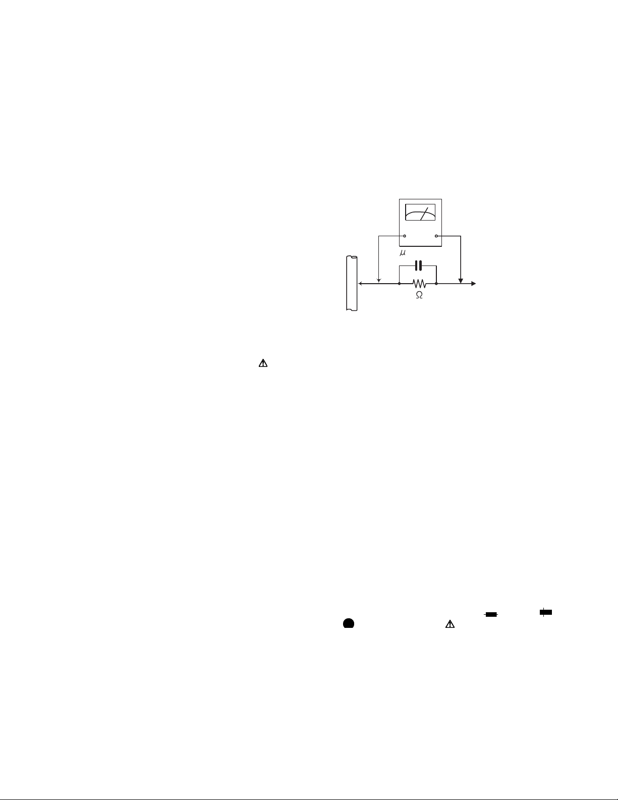
• Alternate check method
Plug the AC line cord directly into the AC outlet. Use an
AC voltmeter having, 1,000Ω per volt or more sensitivity
in the following manner. Connect a 1,500Ω 10W resistor
paralleled by a 0.15µF AC-type capacitor between an ex-
posed metal part and a known good earth ground.
Measure the AC voltage across the resistor with the AC
voltmeter.
Move the resistor connection to each exposed metal
part, particularly any exposed metal part having a return
path to the chassis, and measure the AC voltage across
the resistor. Now, reverse the plug in the AC outlet and
repeat each measurement. Voltage measured any must
not exceed 0.75 V AC (r.m.s.). This corresponds to 0.5
mA AC (r.m.s.).
AC VOLTMETER
(Having 1000
ohms/volts,
or more sensitivity)
0.15 F AC TYPE
Place this
probe on
1500 10W
Good earth ground
1.2 Warning
(1) This equipment has been designed and manufactured to
meet international safety standards.
(2) It is the legal responsibility of the repairer to ensure that
these safety standards are maintained.
(3) Repairs must be made in accordance with the relevant
safety standards.
(4) It is essential that safety critical components are replaced
by approved parts.
(5) If mains voltage selector is provided, check setting for local
voltage.
1.3 Caution
Burrs formed during molding may be left over on some parts
of the chassis.
Therefore, pay attention to such burrs in the case of preforming repair of this system.
1.4 Critical parts for safety
In regard with component parts appearing on the silk-screen
printed side (parts side) of the PWB diagrams, the parts that are
printed over with black such as the resistor ( ), diode ( )
and ICP ( ) or identified by the " " mark nearby are critical
for safety. When replacing them, be sure to use the parts of the
same type and rating as specified by the manufacturer.
(This regulation dose not Except the J and C version)
each exposed
metal part.
1-4 (No.MB362)
Page 5
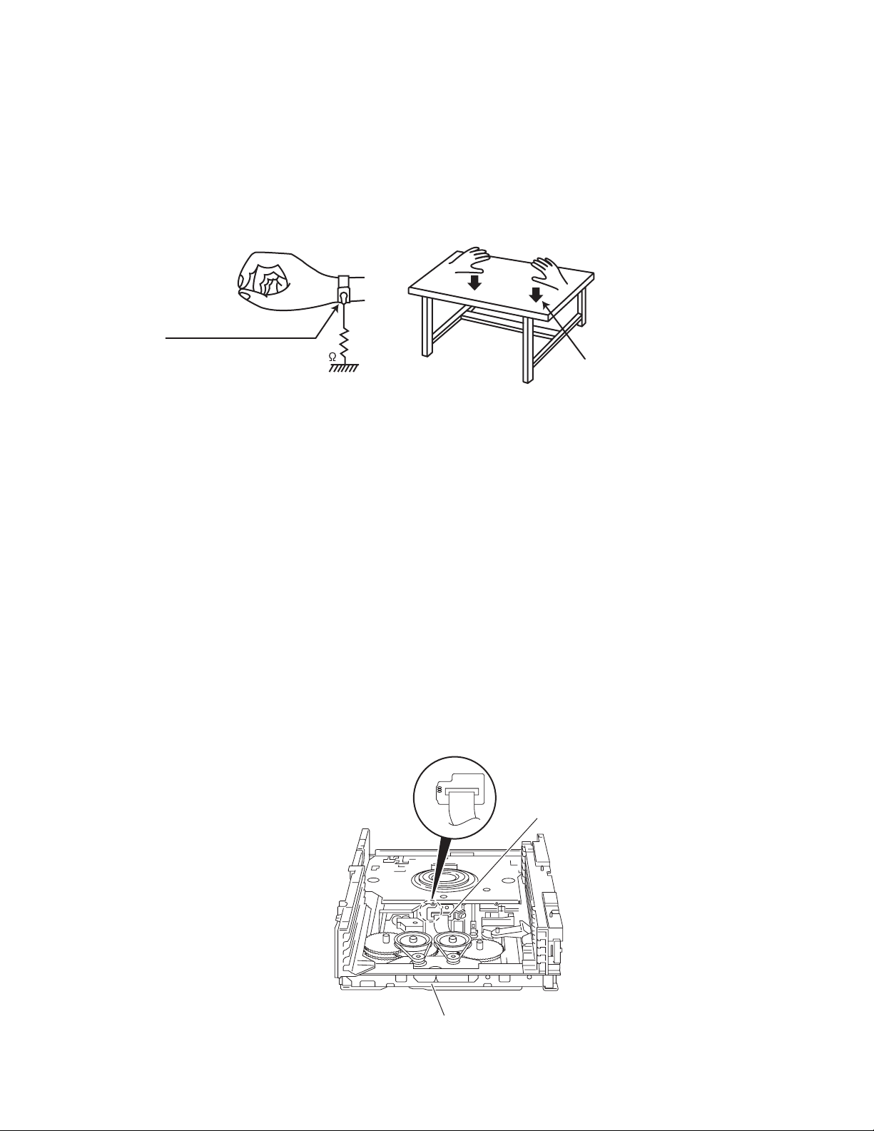
1.5 Preventing static electricity
Electrostatic discharge (ESD), which occurs when static electricity stored in the body, fabric, etc. is discharged, can destroy the laser
diode in the traverse unit (optical pickup). Take care to prevent this when performing repairs.
1.5.1 Grounding to prevent damage by static electricity
Static electricity in the work area can destroy the optical pickup (laser diode) in devices such as laser products.
Be careful to use proper grounding in the area where repairs are being performed.
(1) Ground the workbench
Ground the workbench by laying conductive material (such as a conductive sheet) or an iron plate over it before placing the
traverse unit (optical pickup) on it.
(2) Ground yourself
Use an anti-static wrist strap to release any static electricity built up in your body.
(caption)
Anti-static wrist strap
1M
Conductive material
(conductive sheet) or iron palate
(3) Handling the optical pickup
• In order to maintain quality during transport and before installation, both sides of the laser diode on the replacement optical
pickup are shorted. After replacement, return the shorted parts to their original condition.
(Refer to the text.)
• Do not use a tester to check the condition of the laser diode in the optical pickup. The tester's internal power source can easily
destroy the laser diode.
1.6 Handling the traverse unit (optical pickup)
(1) Do not subject the traverse unit (optical pickup) to strong shocks, as it is a sensitive, complex unit.
(2) Cut off the shorted part of the flexible cable using nippers, etc. after replacing the optical pickup. For specific details, refer to the
replacement procedure in the text. Remove the anti-static pin when replacing the traverse unit. Be careful not to take too long a
time when attaching it to the connector.
(3) Handle the flexible cable carefully as it may break when subjected to strong force.
(4) I t is not possible to adjust the semi-fixed resistor that adjusts the laser power. Do not turn it.
1.7 Attention when traverse unit is decomposed
*Please refer to "Disassembly method" in the text for the pickup unit.
• Apply solder to the short land sections before the flexible wire is disconnected from the connecto on the servo board. (If the flexible
wire is disconnected without applying solder, the pickup may be destroyed by static electricity.)
• In the assembly, be sure to remove solder from the short land sections after connecting the flexible wire.
DVD pickup
DVD changer mechanism assembly
(No.MB362)1-5
Page 6
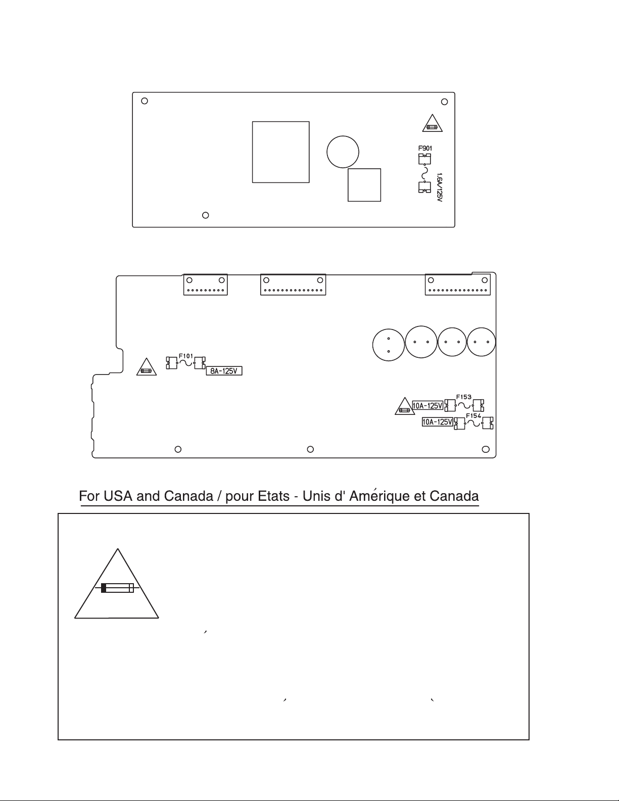
1.8 Importance administering point on the safety
Power supply board
(Center unit)
Mother board
(Subwoofer)
1-6 (No.MB362)
Caution: For continued protection against risk of fire,
replace only with same type 1.6 A/125 V for F901,
8A/125V for F101,10 A/125 V for F153 and F154.
This symbol specifies the type of fast operating fuse.
Precaution: Pour la protection continue contre les
risques d'incendie, remplacer uniquement par le
^
meme type: fusible 1.6 A/125 V pour le F901,
8A/125V pour le F101,10 A/125 V pour le F153 et F154.
Ce symbole specifie le type de fusible a action rapide.
Page 7

SECTION 2
SPECIFIC SERVICE INSTRUCTIONS
This service manual does not describe SPECIFIC SERVICE INSTRUCTIONS.
(No.MB362)1-7
Page 8

SECTION 3
r
DISASSEMBLY
3.1 Main body section
3.1.1 Removing the metal cover
(See Figs. 1 to 4)
(1) From the both sides of the main body, remove the four
screws A attaching the metal cover. (See Figs. 1 and 2.)
(2) From the back side of the main body, remove the three
screws B attaching the metal cover. (See Fig. 3.)
(3) Lift the rear section of the metal cover in the direction of the
arrow while extending the lower sections of the metal cover, release the seven claws a using a longer screwdriver
from the inside as required. (See Fig. 4.)
Note:
Do not damage any parts and boards inside the main body
when releasing the claws a using a longer screwdriver.
Metal cover
A
Fig.1
Metal cover
B
A
Fig.2
Metal cove
Fig.3
Metal cover
Claws aClaws a
1-8 (No.MB362)
Fig.4
Page 9

3.1.2 Removing the front panel assembly
(See Figs. 5 and 6)
• Prior to performing the following procedures, remove the metal
cover.
(1) From the top side of the main body, disconnect the parallel
wires from the connectors (CN456
board. (See Fig. 5.)
(2) Disconnect the card wires from the connectors (CN450
) on the main board. (See Fig. 5.)
CN460
(3) Remove the screw C attaching the earth wires to the main
board. (See Fig. 5.)
Reference:
When attaching the screw C, attach the earth wires with
it. (See Fig. 5.)
(4) From the bottom side of the main body, remove the three
screws D attaching the front panel assembly. (See Fig. 6.)
(5) From the both and bottom sides of the main body, remove
the front panel assembly in the direction of the arrow while
releasing the joints b and c. (See Fig. 6.)
, CN457) on the main
,
Front panel assembly
Main board
Card wire
CN457
CN450
CN456
Parallel wires
C
Earth
wires
CN460
Card wire
Front panel assembly
Fig.5
Joint c Joint bJoint b
D
Fig.6
(No.MB362)1-9
Page 10

3.1.3 Removing the DVD changer mechanism assembly
(See Fig. 7)
• Prior to performing the following procedures, remove metal
cover and front panel assembly.
(1) From the top side of the main body, remove the screw E at-
taching the wire protection board to the main board.
(2) Take out the wire protection board, and disconnect the
card wires from the connectors (CN401
main board.
Reference:
When attaching the wire protection board, attach the
wire protection board after connecting the card wires to
the connectors (CN401
(3) Remove the four screws F attaching the DVD changer
mechanism assembly on the bottom chassis.
(4) Take out the DVD changer mechanism assembly in the up-
ward direction.
Reference:
When attaching the DVD changer mechanism assembly, align
the holes of the DVD changer mechanism assembly to the projections d on the bottom chassis.
3.1.4 Removing the rear panel
(See Fig. 8)
• Prior to performing the following procedures, remove the metal
cover.
(1) From the back side of the main body, remove the screw G
and eleven screws H attaching the rear panel.
to CN403) on the main board.
to CN403) on the
F
DVD changer mechanism assembly
Projections d
Wire protection board
F
G
F
E
Fig.7
CN402
Card wires
CN401
Bottom
chassis
CN403
Main
board
H
H
Rear panel
Fig.8
1-10 (No.MB362)
Page 11

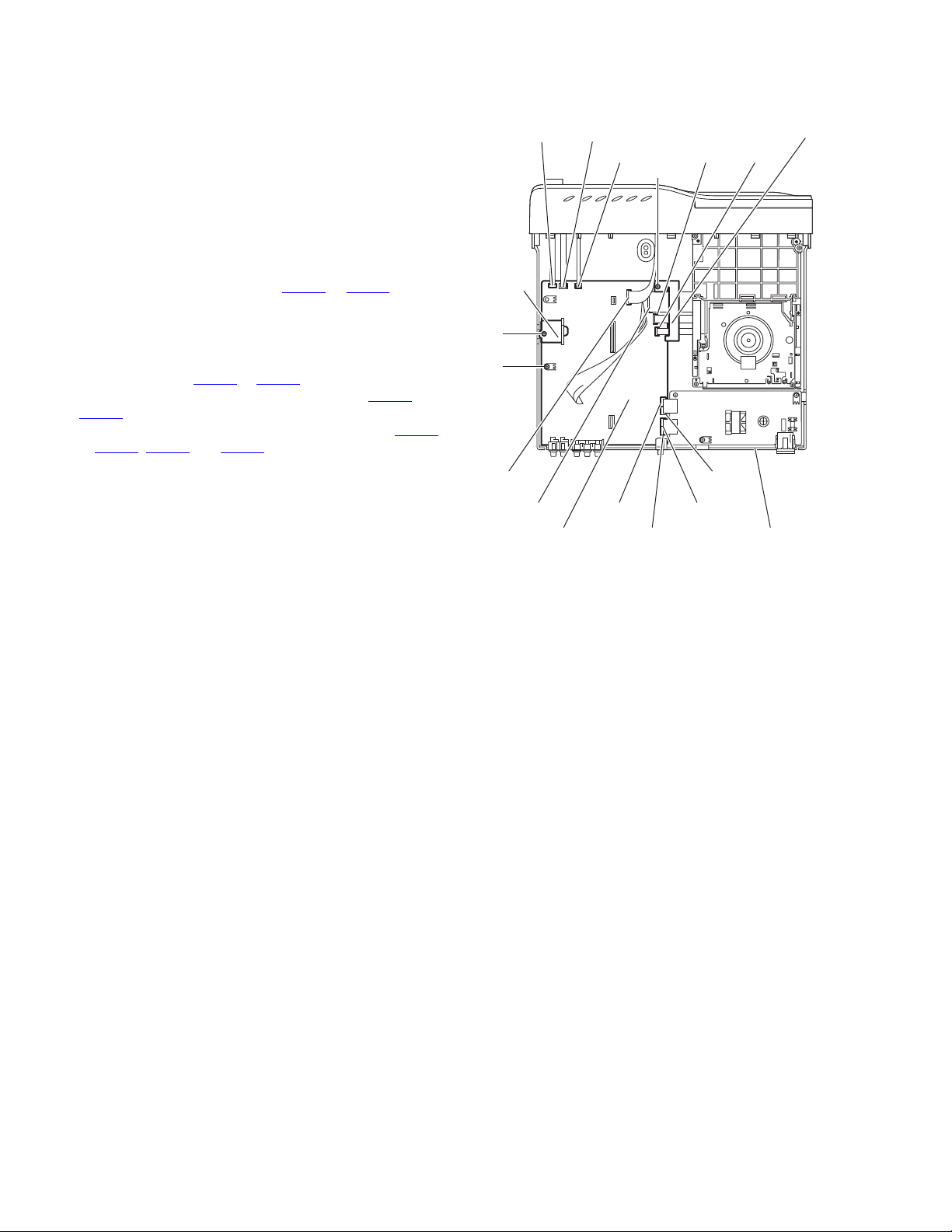
3.1.5 Removing the audio & digital input board
(See Figs. 9 and 10)
• Prior to performing the following procedures, remove the metal
cover.
(1) From the top side of the main body, disconnect the card
wires from the connectors (CN411
board. (See Fig. 9.)
(2) Remove the screw J attaching the earth wires to the main
board. (See Fig. 9.)
Reference:
When attaching the screw J, attach the earth wires with
it. (See Fig. 9.)
(3) From the back side of the main body, remove the screw K
and two screws L attaching the audio & digital input board
to the rear panel. (See Fig. 10.)
(4) Move the audio & digital input board in the direction of the
arrow, and release the claw e of bracket board. (See Fig.
9.)
(5) Take out the audio & digital input board from the main
body.
3.1.6 Removing the tuner
(See Figs. 9 and 10)
• Prior to performing the following procedures, remove the metal
cover.
(1) From the top side of the main body, disconnect the card
wire from the connector CN1
(2) From the back side of the main body, remove the two
screws M attaching the tuner to the rear panel. (See Fig.
10.)
(3) Take out the tuner from the main body.
3.1.7 Removing the power supply board
(See Figs. 9 and 10)
• Prior to performing the following procedures, remove the metal
cover.
(1) From the top side of the main body, disconnect the parallel
wires from the connectors (CN404
board. (See Fig. 9.)
(2) Remove the three screws N attaching the power supply
board. (See Fig. 9.)
(3) From the back side of the main body, remove the screw P
attaching the power supply board to the rear panel. (See
Fig. 10.)
(4) Take out the power supply board from the main body.
Reference:
Remove the rear panel as required. (See "3.1.4 Removing the
rear panel")
, CN412) on the main
on the tuner. (See Fig. 9.)
to CN407) on the main
Main board
Card wires
Earth
wire
CN412
CN411
J
Bracket
board
Craw e
CN407
CN406
CN1
Card wire
Audio & digital input board
KP
CN405
Tuner
ML
N
Power supply board
N
CN404
Parallel wires
Fig.9
Rear panel
Fig.10
(No.MB362)1-11
Page 12
3.1.8 Removing the main board
(See Fig. 11)
• Prior to performing the following procedures, remove the metal
cover, rear panel, audio & digital input board and tuner.
(1) From the top side of the main body, remove the screw Q
attaching the bracket board and take the bracket board.
(2) Remove the screw R and screw R' attaching the main
board on the bottom chassis.
Reference:
When attaching the screw R', attach the wire protection
board with it.
(3) Take out the wire protection board, and disconnect the
card wires from the connectors (CN401
main board.
Reference:
When attaching the wire protection board, attach the
wire protection board after connecting the card wires to
the connectors (CN401
(4) Disconnect the card wires from the connectors (CN450 and
) on the main board.
CN460
(5) Disconnect the parallel wires from the connectors (CN404
to CN407, CN456 and CN457) on the main board.
(6) Take out the main board from the main body.
to CN403) on the main board.
to CN403) on the
CN460
Bracket
board
Q
R
CN450
CN456
CN457
Wire protection board
CN402CN401
R'
CN406
CN403
Main board
CN407
CN404
Fig.11
CN405
Bottom chassis
1-12 (No.MB362)
Page 13
3.2 Front panel assembly section
• Prior to performing the following procedures, remove the front panel assembly from the main body. (See "Removing the front panel
assembly")
3.2.1 Removing the phone jack board
(See Fig. 1)
(1) From the inside of the front panel assembly, remove the
screw A attaching the phone jack board.
(2) Take out the phone jack board from the front panel assem-
bly.
3.2.2 Removing the bracket board
(See Fig. 1)
(1) From the inside of the front panel assembly, remove the
two screws B attaching the bracket board.
Reference:
When attaching the connect board, align the projections
of the bracket board to the slots a and b of the front panel
assembly.
(2) Take out the bracket board from the front panel assembly.
3.2.3 Removing the operation board
(See Fig. 2)
• Prior to performing the following procedures, remove the
bracket board.
(1) From the inside of the front panel assembly, remove the
three screws C attaching the operation board.
Reference:
When attaching the operation board, align the projections c of the front panel assembly to the holes of the operation board.
(2) Take out the operation board.
3.2.4 Removing the power key board
(See Fig. 2)
• Prior to performing the following procedures, remove the
bracket board.
(1) From the inside of the front panel assembly, remove the
two screws D attaching the power key board.
(2) Take out the power key board and remove the solder from
the soldered point d to remove the parallel wire.
Headphone board
A
Projections c
Operation board
Slot b
Slot a
BB
Bracket board
Fig.1
Solder section d
Fig.2
Front panel assembly
DC
Power key board
Front panel assembly
(No.MB362)1-13
Page 14
3.2.5 Removing the front board
e
(See Figs. 3 and 4)
• Prior to performing the following procedures, remove the
phone jack board, bracket board and operation board.
(1) From the front side of the front panel assembly, pull out the
volume knob in the direction of the arrow. (See Fig. 3.)
(2) From the inside of the front panel assembly, remove the six
screws E attaching the front board. (See Fig. 4.)
(3) Take out the front board and remove the solder from the
soldered point e to remove the parallel wire. (See Fig. 4.)
Front panel assembly
Volume knob
Fig.3
E
Front board
Front panel ass
Solder section e
Fig.4
1-14 (No.MB362)
Page 15

3.3 DVD changer mechanism assembly section
Remove the DVD changer mechanism assembly from the main body. (See "Removing the DVD changer mechanism assembly".)
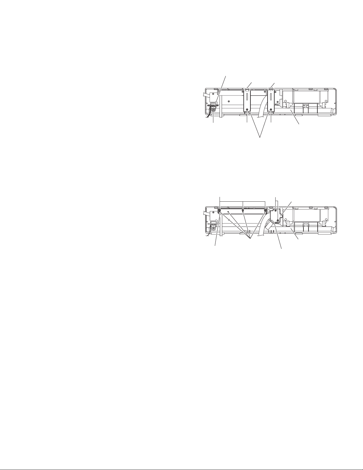
3.3.1 Removing the tray assemblies
(See Figs.1 to 5)
(1) From the top side of the main body, remove the two screws
A from the top cover and release the two joints a on the
both sides of the DVD changer mechanism assembly. (See
Figs.1 and 2.)
(2) Remove the two rods from the top cover and remove the
top cover from the lifter assembly. (See Figs.1 and 2.)
(3) Remove the open det. lever on the left side of the DVD
changer mechanism assembly. (See Fig.3.)
(4) From the right side of the DVD changer mechanism as-
sembly, draw out the tray assemblies toward the front while
pushing the part b of the side (R) assembly. (See Figs.4
and 5.)
Note:
The tray can be locked if all tray assemblies are attached.
(5) From the topside of the DVD changer mechanism assem-
bly, move the stopper tabs c in the direction of the arrow
and release them. Pull out the tray assemblies from the
DVD changer mechanism assembly. (See Fig. 5.)
Note:
Remove the tray assembly from top tray 5 in order.
Reference:
When reattaching the tray assembly, or when removing the
disc remaining inside, refer to another section "3.3.15 Taking
out the disc in the play mode".
A
a
Lifter assembly
Fig.1
Rods
Top cover
A
a
Rods
Top cover
a
a
Lifter assembly
Fig.2
(No.MB362)1-15
Page 16

Fig.3
r
Open det. leve
Tray assemblies
c
b
Side(R) assembly
Fig.4
Tray assembly
1-16 (No.MB362)
Fig.5
Page 17

3.3.2 Removing the DVD servo board
(See Figs.6 to 8)
Caution:
Solder the short land sections d on the DVD pickup before disconnecting the card wire extending from the DVD pickup. If
you do not follow this instruction, the DVD pickup may be damaged.
(1) From the topside of the DVD changer mechanism assem-
bly, solder the short land sections d on the DVD pick up.
(See Fig.6.)
(2) From the bottom side of the DVD changer mechanism as-
sembly, disconnect the card wire from the connectors
(CN201
Reference:
(3) Disconnect the wires from the connectors (CN452
on the DVD servo board. (See Fig.7.)
(4) Remove the two screws B attaching the DVD servo board.
(See Fig.7.)
(5) From the reverse side of the DVD servo board, release the
lock of the connector CN101
and disconnect the card wire. (See Fig.8.)
Caution:
Unsolder the solders from the short land sections d after reassembling. (See Fig.6.)
3.3.3 Removing the switch board
(1) From the bottom side of the DVD changer mechanism as-
sembly, remove the screw C attaching the switch board on
the DVD changer mechanism assembly.
(2) Disconnect the wires from the connectors (CN452
on the DVD servo board.
(3) Release the wires from the section f and remove the switch
board.
(4) Release the wires from the sections g and remove the
switch board.
Reference:
When reassembling, pass the wires through the sections (f, g)
as before.
, CN451) on the DVD servo board. (See Fig.7.)
When connecting the card wire to the connector CN451
pass it through the sections e on the DVD traverse
mechanism assembly. (See Fig.7.)
, CN453)
in the direction of the arrow
(See Fig.7)
, CN453)
d
,
DVD changer mechanism assembly
Fig.6
DVD changer mechanism assembly
e
CN451
DVD pickup
CN453
f
g
Switch board
B
C
CN201
DVD servo board
DVD traverse mechanism assembly
DVD servo board
B
Fig.7
CN452
CN101
Fig.8
Lock
(No.MB362)1-17
Page 18

3.3.4 Removing the motor board
(See Figs.9 and 10)
(1) From the top side of the DVD changer mechanism assem-
bly, remove the two belts from the motor pulleys. (See
Fig.9.)
Note:
Take care not to attach grease on the belt.
(2) Remove the two screws D attaching the motors to the load-
er assembly. (See Fig.9.)
(3) From the bottom side of the DVD changer mechanism as-
sembly, remove the two screws E. (See Fig.10.)
(4) Disconnect the connector CN2
tray switch board and remove the motor board. (See
Fig.10.)
(5) Disconnect the card wire from the connector CN1
forward side of the motor board. (See Fig.10.)
Note:
When connecting the card wire, let the card wire through the
slots h of the motor board. (See Fig.10.)
Reference:
You need not to remove the tray assemblies, and in such case,
move it.
3.3.5 Removing the motor
(See Fig. 10)
• Remove the motor board.
(1) From the reverse side of the motor board, unsolder the four
soldered sections i on the motor board.
(2) From the forward side of the motor board, remove the mo-
tors.
on the motor board from the
on the
D
Belt
Motor Motor
Motor pulleys
Belt
D
Loader assembly
Fig.9
Motors
Motor board
i
Tray switch
board
E
CN2
CN1
h
DVD changer mechanism assembly
Fig.10
Motors
Motor board
E
1-18 (No.MB362)
Page 19

3.3.6 Removing the DVD traverse mechanism assembly
(See Fig.11)
• Remove the tray assemblies and DVD servo board.
(1) From the bottom side of the DVD changer mechanism as-
sembly, remove the three screws F attaching the DVD
traverse mechanism assembly.
(2) Remove the wires from the section j.
(3) Take out the DVD traverse mechanism assembly from the
DVD changer mechanism assembly.
DVD changer mechanism assembly
F
j
F
F
DVD traverse mechanism assembly
Fig.11
(No.MB362)1-19
Page 20

3.3.7 Removing the DVD pickup
(See Figs.12 to 14)
• Remove the tray assemblies, DVD servo board and DVD
traverse mechanism assembly.
(1) From the top side of the DVD traverse mechanism assem-
bly, release the lock of the connector on the DVD pickup
and disconnect the card wire in the direction of the arrow.
(See Fig.12.)
(2) Turn the screw shaft gear in the direction of the arrow 1 to
move the DVD pickup in the direction of the arrow 2. (See
Fig.12.)
(3) Remove the screw G attaching the feed bracket and re-
move the feed bracket from the sections k. (See Fig.12.)
(4) Release the claw m of the thrust spring in the direction of
the arrow and remove the thrust spring. (See Fig.12.)
(5) Remove the guide shaft from the sections (n, p) on the
C.TM chassis. (See Fig.13.)
(6) Remove the section q of the DVD pickup. (See Fig.13.)
(7) Remove the two screws H attaching the rack arm spring
and rack arm. (See Fig.14.)
(8) Pull the guide shaft from the DVD pickup in the direction of
the arrow. (See Fig.14.)
3.3.8 Attaching the DVD pickup
(See Figs.12 to 14)
(1) Attach the guide shaft to the DVD pickup and attach the
rack arm spring and rack arm with the screws H. (See
Fig.14.)
(2) Attach the section q of the DVD pickup to the C.TM chassis
first and attach the guide shaft to the sections (n, p). (See
Fig.13.)
Reference:
When attaching the guide shaft to the section p, attach it
under the rod spring. (See Fig.13.)
(3) Attach the thrust spring and feed bracket with the screw G.
(See Fig.12.)
(4) Turn the screw shaft gear in the direction of the arrow 1 to
move the DVD pickup in the direction of the arrow 2. (See
Fig.15.)
(5) Connect the card wire to the connector on the DVD pickup.
(See Fig.15.)
DVD traverse mechanism assembly
Thrust spring
Connector
Screw shaft gear
DVD pickup
Fig.12
DVD pickup
1
k
Thrust spring
q
Feed bracket
2
G
m
1-20 (No.MB362)
p
Rod spring
n
Guide shaft
C.TM chassis
Fig.13
Page 21

Guide shaft
DVD pickup
Rack arm
H
Rack arm spring
Fig.14
Tray assembly
c
Fig.15
(No.MB362)1-21
Page 22

3.3.9 Removing the spindle motor board
(See Figs.16 and 17)
• Remove the tray assemblies, DVD servo board and DVD
traverse mechanism assembly.
(1) From the top side of the DVD traverse mechanism assem-
bly, remove the wires from the soldered sections r on the
spindle motor board. (See Fig.16.)
(2) From the bottom side of the DVD traverse mechanism as-
sembly, remove the three screws J attaching the spindle
motor board. (See Fig.17.)
Reference:
When attaching the spindle motor board, let the card wire
through the hole s on the C.TM chassis. (See Fig.17.)
DVD traverse mechanism assembly
Spindle motor board
r
Fig.16
DVD traverse mechanism assembly
s
J
C.TM chassis
Fig.17
1-22 (No.MB362)
Page 23

3.3.10 Removing the feed motor
(See Figs.18 and 19)
• Remove the tray assemblies and DVD traverse mechanism
assembly.
(1) From the top side of the DVD traverse mechanism assem-
bly, remove the screw K attaching the feed bracket and remove the feed bracket from the sections t. (See Fig.18.)
(2) Release the claw u of the thrust spring in the direction of
the arrow and remove the thrust spring. (See Fig.18.)
(3) Remove the screw shaft from the section v and remove it
in the direction of the arrow. (See Fig.19.)
(4) Remove the middle gear. (See Fig.19.)
(5) Remove the screw L attaching the feed motor to the C.TM
chassis. (See Fig.19.)
(6) Remove the wires from the soldered sections w on the
spindle motor board. (See Fig.19.)
(7) Take out the feed motor from the motor base.
Reference:
After attaching the feed motor, pass the wires through the sections x on the C.TM chassis as before. (See Fig.19.)
Feed bracket
Thrust spring
K
t
Thrust spring
Spindle motor board
w
x
Fig.18
Middle gear
v
Screw shaft
u
C.TM chassis
Fig.19
L
(No.MB362)1-23
Page 24

3.3.11 Removing the side (L) and tray switch board
(See Figs.20 to 22)
• Remove the tray assemblies.
(1) From the topside of the DVD changer mechanism assem-
bly, remove the two screws M attaching the side (L). (See
Fig.20.)
(2) From the left side of the DVD changer mechanism assem-
bly, disconnect the connector CN3
from the motor board and detach the side (L) in an upward
direction. (See Fig.21.)
(3) Remove the screw N attaching the tray switch board to the
side (L). (See Fig.22.)
(4) Release the joint tab y of the side (L) in the direction of the
arrow 1 and release the joint tab z while removing the tray
switch board in the direction of the arrow 2. (See Fig.22.)
on the tray switch board
SIde(L)
M
M
DVD changer mechanism assembly
Fig.20
M
Side(L)
M
CN3
Tray switch board
Motor board
Side(L)
Fig.21
y
1
1-24 (No.MB362)
2
z
Tray switch board
N
Fig.22
Page 25

3.3.12 Removing the side (R) assembly
(See Fig.23 to 27)
• Remove the tray assemblies and DVD servo board.
(1) From the inside of the side (R) assembly, release the two
tabs aa of the gear cover and remove the gear cover outward. (See Figs.23 and 24.)
(2) From the right side of the DVD changer mechanism as-
sembly, remove the elevator spring attached to the hook
ab of the loader assembly. (See Figs.24 and 25.)
(3) From the top side of the DVD changer mechanism assem-
bly, turn the gear 1 clockwise to move the elevator cam
rearward. (See Fig.25.)
(4) Move the two slots ac and joint ad of the elevator cam and
remove the elevator cam outward. (See Fig.25.)
(5) Remove the three screws P and detaches the side (R) as-
sembly upward. (See Figs.26 and 27.)
Note:
When reattaching the side (R) assembly, make sure to fit the
shaft (part ae) into the slot of the select lever. (See Fig.26.)
Side(R) assembly
aa
P
Elevator spring
ac
Fig.25
P
ae
ab
Elevator cam
acad
Select lever
Side(R) assembly
Gear cover
Loader assembly
P
Fig.23
Elevator spring
Gear 1
Side(R) assembly
Fig.26
P
ab
P
Fig.24
Side(R) assembly
Fig.27
(No.MB362)1-25
Page 26

3.3.13 Removing the lifter assembly
(See Figs.28 to 32)
• Remove the tray assemblies, DVD servo board, side (L) and
side (R) assembly.
(1) (1) From the top side of the DVD changer mechanism as-
sembly, turn the gear 1 clockwise to move the lifter assembly upward. (See Figs.28 and 29.)
(2) Turn the gear 2 clockwise to move the hook toward the
front until it stops. (See Figs.28 and 29.)
(3) Move the hook stopper in the direction of the arrow 2 while
pushing the tab af of the hook stopper to unlock it in the direction of the arrow 1 and release four joints ag to detach
from the rack holder. (See Fig.30.)
(4) Release the rod (L) from part ah. (See Fig.30.)
(5) Turn the gear 1 clockwise again to move the lifter assembly
upward. (See Fig.31.)
(6) Remove the lifter assembly from the DVD changer mecha-
nism assembly upward at the positions ai where the four
pins on the both sides of the lifter assembly fit to the notch-
es of the loader assembly. (See Fig.31.)
(7) Move the lifter assembly in the direction of the arrow and
release it from the hook. (See Fig.32.)
Hook stopper
Gear 2
Gear 1
ag
Rack holder
af
Hook
ag
1
ag
Hook stopper
Fig.30
Lifter assembly
ag
2
Rod(L)
ai
ah
ai
Hook
Gear 2
Lifter assembly
Fig.28
Gear 1
Lifter assembly
Gear 1
ai
Loader assembly
Fig.31
Lifter assembly
ai
Hook stopper
1-26 (No.MB362)
Hook
Fig.32
Hook
Fig.29
Page 27

3.3.14 Removing the sensor board and SV resistor
(See Fig.33)
• Remove the tray assemblies, side (L), side (R) assembly and
lifter assembly.
(1) Remove the solders from the soldered sections aj on the
sensor board and remove the wires.
(2) Remove the two screws Q and take out the sensor board
with the SV resistor.
Reference:
• Remove the soldered section ap on the sensor board as required.
• When reassembling, pass the wires through the slot ak of
the sensor board as before.
Note:
When reattaching the SV. resister, fit the projection am on the
bottom of the SV. resister into slot an of the sensor slider.
Sensor board
Q
ap
Q
ak
aj
SV resistor
am
an
SV resistor
Slider
Fig.33
(No.MB362)1-27
Page 28

3.3.15 Taking out the disc in the play mode
(See Fig.34 to 37)
Reference:
Refer to "3.3.1 Removing the tray assemblies".
(1) From the top side of the DVD changer mechanism assem-
bly, remove the top cover.
(2) Unlock the tray assemblies and draw out the tray assem-
blies toward the front.
(3) From the top side of the DVD changer mechanism assem-
bly, turn the gear 1 clockwise to move the lifter assembly
upward. (See Fig.34.)
(4) Turn the gear 2 clockwise to move the sub tray remaining
inside the lifter assembly toward the front, then pull out.
(See Fig.34.)
(5) Take out the disc on the sub tray. (See Fig.35.)
(6) After clearing away the disc, insert the sub tray into the
main tray. (See Fig.36.)
Note:
When reattaching the sub tray, move the tray stopper on
the bottom of the main tray in the direction of the arrow
to lock the sub tray certainly. (See Figs.36 and 37.)
(7) Push the tray assembly toward the DVD changer mecha-
nism assembly and reattach.
Tray assembly
Gear 2
Gear 1
Sub tray
Fig.34
Tray assembly
Fig.35
Disc
Sub tray
1-28 (No.MB362)
Page 29

Tray stopper
r
Main tray
Sub tray
Fig.36
Tray stoppe
Fig.37
(No.MB362)1-29
Page 30

3.4 Speaker section
3.4.1 Removing the amplifier assembly
(See Figs.1 to 3)
(1) From the back side of the speaker main body, remove two
screws A attaching the amplifier assembly. (See Fig.1)
(2) From the bottom side of the speaker main body, remove
the eight screws B attaching amplifier assembly. (See
Fig.2)
(3) From the left side of the speaker main body, move the am-
plifier assembly backward and disconnect the wire from the
connector CN274
Reference:
After connecting the wire to the connector CN274
er board, bundle the wire by the wire clamp. (See Fig.3)
on the mother board. (See Fig.3)
on the moth-
A
Amplifier
assembly
Fig.1
Speaker main body
Fig.2
Amplifier assembly Speaker main body
B
B
1-30 (No.MB362)
Mother board
CN274
Fig.3
Wire clamp
Page 31

3.4.2 Removing the rear panel
r
(See Figs.4 and 5)
• Prior to performing the following procedures, remove the am-
plifier assembly.
(1) From the back side of the amplifier assembly, remove the
four screws C, two screws D and screw E attaching the rear
panel. (See Fig.4)
(2) From the top side of the amplifier assembly, take out the
rear panel with fan motor, and disconnect the wire from the
connector CN371
3.4.3 Removing the fan motor
(See Figs.4 and 5)
• Prior to performing the following procedures, remove the am-
plifier assembly.
(1) From the back side of the rear panel, remove the two
screws F attaching the fan motor. (See Fig.4)
(2) From the top side of the amplifier assembly, take out the
fan motor and disconnect the wire from the connector
on the mother board. (See Fig.5)
CN371
on the mother board. (See Fig.5)
C
D
E
F
C
Rear panel
Fig.4
3.4.4 Removing the heat sink BKT
(See Figs.6 and 7)
• Prior to performing the following procedures, remove the am-
plifier assembly and rear panel.
(1) From the left side of the amplifier assembly, remove the
wires from the wire clamp on the heat sink BKT. (See Fig.6)
(2) From the left side of the amplifier assembly, remove the
four screws G attaching the heat sink BKT. (See Fig.7)
(3) Take out the two heat sink BKT.
Reference:
After attaching the heat sink BKT, bundle the wire by the wire
clamp. (See Fig.6)
CN371
Amplifer assembly
Wire
Heat sink BKT
Mothe
board
Fan motor
Fig.5
Wire clamp
Wire
Fig.6
Mother board
G G
Mother board
Fig.7
(No.MB362)1-31
Page 32

3.4.5 Removing the mother board
(See Figs.8 and 9)
• Prior to performing the following procedures, remove the am-
plifier assembly, rear panel and heat sink BKT.
(1) From the top side of the amplifier assembly, remove the
two screws H attaching the mother board. (See Fig.8)
(2) From the left side of the amplifier assembly, disconnect the
wires from the connectors CN102
er board. (See Fig.9)
(3) Disconnect the power cord from the connector CN101
the mother board, and take out the power cord. (See Fig.9)
(4) Disconnect the mother board from the connector CN271
and CN273 on the amp. board, and take out the
CN272
mother board assembly from the amplifier assembly. (See
Fig.9)
and CN151 on the moth-
on
,
H H
Mother board
Fig.8
Amplifier assembly
Power cord
Wires
3.4.6 Removing the amp. board
(See Fig.10)
• Prior to performing the following procedures, remove the am-
plifier assembly, rear panel, heat sink BKT and mother board.
(1) From the left side of the amplifier assembly, remove the
nine screws J attaching the amp. board.
(2) Take out the amp. board with the heat sink.
CN102
Mother board
Amp. board
J
CN272 CN271
CN101
Fig.9
Heat sink
Fig.10
CN151
CN273
1-32 (No.MB362)
Page 33

3.4.7 Removing the heat sink
(See Figs.11 and 12)
• Prior to performing the following procedures, remove the am-
plifier assembly, rear panel, heat sink BKT, mother board and
amp. board.
(1) Remove the four screws K attaching the power IC to the
heat sink. (See Fig.11)
(2) From the reverse side of the amp. board, remove the three
screws M attaching the heat sink to the amp. board. (See
Fig.12)
(3) Take out the heat sink.
3.4.8 Removing the power IC
(See Fig. 12)
• Prior to performing the following procedures, remove the am-
plifier assembly, rear panel, heat sink BKT, mother board,
amp. board and heat sink.
(1) From the reverse side of the amp. board, remove the sol-
ders from the solder points a on the amp. board.
(2) Take out the power IC.
Power ICHeat sink
KK
Amp. board
Fig.11
Amp. board Solder points a
3.4.9 Removing the LED board
(See Fig.13)
• Prior to performing the following procedures, remove the am-
plifier assembly and rear panel.
(1) From the front side of the amplifier assembly, cut off the tie
bands.
(2) Remove the two screws N attaching the LED board.
(3) From the reverse side of the LED board, remove the solder
from the solder point b on the LED board.
M
Fig.12
Tie bands
LED board
Solder point b
N
Fig.13
(No.MB362)1-33
Page 34

3.4.10 Removing the power transformer
(See Figs.14 and 15)
• Prior to performing the following procedures, remove the am-
plifier assembly and rear panel.
(1) From the top side of the amplifier assembly, disconnect the
wires from the connectors CN102
er board. (See fig.14)
(2) Remove the four screws P attaching the power transform-
er, and take out the power transformer from the amplifier
assembly. (See fig.15)
Reference:
• When attaching the power transformer, attach the screws P
with the barrier. (See fig.15)
• After connect the wires from the connectors CN102
CN151, bundle the wire by the wire clamp. (See Fig.14)
• When changing the new power transformer, renew the new
spacer (See fig.15)
and CN151 on the moth-
and
Amplifier assembly
CN102 Mother board
Wire clamp
CN151
Fig.14
Spacer
P
Barrier
P
Power transformer
Fig.15
1-34 (No.MB362)
Page 35

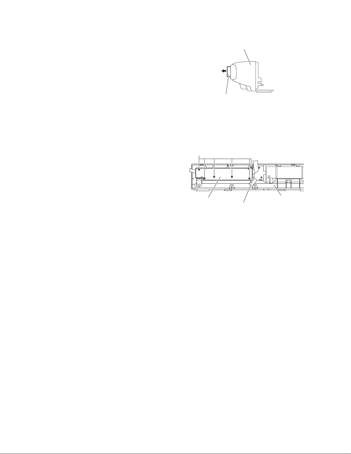
3.4.11 Removing the speaker net
(See Figs.16 and 17)
(1) From side of the speaker main body, insert the tip of the
flat-bladed screwdriver or similar tool into the space between the speaker main body and speaker net, and lift the
speaker net little by little to remove. (See Fig.16)
Note:
To prevent damaging the speaker net and speaker main
body, insert cushioning plates etc. and below the tip of
the flat-bladed screwdriver or similar tool.
(2) From right side of the speaker main body, release the nine
joint c, and take out the speaker net from the speaker main
body. (See Fig.17)
Speaker net
Speaker main body
Flat-bladed
screwdriver,etc.
Chshioning
plate,etc.
Fig.16
Speaker net
Fig.17
Joint c
(No.MB362)1-35
Page 36

3.4.12 Removing the speaker
(See Figs.18 and 19)
• Prior to performing the following procedures, remove the
speaker net.
(1) From right side of the speaker main body, remove the eight
screws Q attaching the speaker. (See Fig.18)
(2) Take out the speaker from the speaker main body. (See
Fig.19)
(3) Disconnect the wires from the terminal of the speaker. (See
Fig.19)
QQ
Speaker
Fig.18
TerminalSpeaker main body
Fig.19
Speaker
1-36 (No.MB362)
Page 37

SECTION 4
ADJUSTMENT
4.1 Special mode
4.1.1 Outline
The contents in the special mode of operation, and the definition of a key (remote controller or main unit)
4.1.2 Special mode
1.DVD TEST MODE
It goes into the TEST mode of DVD.
DVD TEST mode is canceled by except DVD source, and POWER OFF.
It is referring to the "4.2 DVD test mode" for details.
Insert the power cord in an outlet while
pressing the
on the main unit simultaneously.
2.DVD NORMAL INITIALIZE
Initialize DVD backend memory.
<RDS> segment of FL will light up if successful.
It is referring to the "4.2 DVD test mode" for details.
"POWER"
A main unit entered in the
DVD TEST MODE.
and "PLAY" keys
Press the "PAUSE" key on the remote
controller during the DVD test mode.
DVD initialization is completed
3.DVD FULL INITIALIZE
It is referring to the "4.2 DVD test mode" for details.
Press the 1.5 second "F.SKIP" key on the remote
controller during the DVD test mode.
DVD initialization is completed
4.DVD REGION CHECK
FL display in DVD TEST MODE.
It is referring to the "4.2 DVD test mode" for details.
Press the "MENU" key on the remote
controller during the DVD test mode.
A region No. display
(No.MB362)1-37
Page 38

5.FORCED NTSC MODE
It is made compulsive NTSC mode.
From this, with regards to the input of NTSEL_SW, there is nothing only
at the time of 1st power on, and it performs NTSC starting.
(Command specification is performed to a module.)
A mode clearance is performed by power off.
VIDEO FORMAT change is prohibited during Forced NTSC mode.
Insert the power cord in an outlet while
"
pressing the "POWER
and "PAUSE" keys
on the main unit simultaneously.
A main unit entered in the
NTSC mode compulsively.
6.TRAY LOCK
A loader mechanism's tray lock is carried out. In the tray lock function ON state,
EJECT processing is not performed to the EJECT key.
And , a LOCK display is performed at this time.
When it turns off a tray lock function, STOP and EJECT KEY are pushed simultaneously again.
Back up ON/OFF of a tray lock.
Press the "STOP" and "OPEN/CLOSE1" keys
on the remote controller at standby.
A tray lock is completed.
4.1.3 4.1.3 Upgrading of firmware (DVD UPGRADE)
The latest firmware for upgrading is updated in "Optical disc CSG" page in JS-net. At the time of service, compare the version of the
product and the latest version, and upgrade the old version into the latest version.
(1) Press "STANDBY/ON" key of the main body to turn it on.
(2) Push "OPEN/CLOSE" key of the main body, and insert the upgrade disc in the tray.
(3) When reading the data of the disc, the OSD screen is displayed "VERSION UP DISC", "PROGRAM & DESTINATION MODE"
and "READING..".
(4) When the screen changes from "READING.." to "WRITING..", upgrading starts.
(5) After writing the data of the disc, the screen is displayed "OPEN".
(6) Take out the disc, and press "STANDBY/ON" key of the main body.
(7) When the stand-by indicator is lighted, upgrading is completed.
(8) Set the main body at test mode, and confirm the version of the firmware. (Refer to "4.2 Method of displaying version firmware".)
4.1.4 Upgrading of system microcomputer (ROM CORRECTION)
(1) Press "STANDBY/ON" key of the main body to turn it on.
(2) Push "OPEN/CLOSE" key of the main body, and insert the upgrade disc in the tray.
(3) When reading the data of the disc, the OSD screen is displayed "VERSION UP DISC", "SYSCON UPG MODE" and "READ-
ING..".
(4) When the screen changes from "READING.." to "WRITING..", system data is written.
(5) After writing the data of the disc, the FL display of the main body is displayed "COMPLETE".
(6) Take out the disc, and press "STANDBY/ON" key of the main body.
(7) When the stand-by indicator is lighted, upgrading is completed.
(8) Set the main body at test mode, and confirm the version of the system microcomputer. (Refer to "4.2 Method of displaying ver-
sion firmware".)
1-38 (No.MB362)
Page 39

4.2 DVD TEST MODE
Refer to "4.2.2 Indication of FL display in the DVD test mode" as required
Insert the power cord in an outlet while
pressing the "POWER
"
and "PLAY" keys
on the main unit simultaneously.
FL indication
TEST bb#
It is made POWER ON in test mode, and VERSION is displayed on FL.
TEST bb#
Press the "PAUSE" key on the main unit.
FL indication
TEST bb#
The initialization state (The 11th figure)
"3" : FULL initialization end
"0" : NORMAL initialization end
"Blank" : Initialization un-ending
The study state (The 10th figure)
"3" : DVD Study un-completing, CD Study un-completing
"2" : DVD Study completing, CD Study un-completing
"1" : DVD Study un-completing, CD Study completing
"0" : DVD Study completing, CD Study completing
Region code display
The study state and an initialization state from a back end are
displayed on the 10th and 11th figure of FL display.
Destination VERSION id displayed.
The display to the VERSION code is as follows.
JC / 1U / D / E / 2U / 3U / UB / UT / 4U / UY / EE / UF
NORMAL initialization
segment of FL is RDS on at the time of the completion of
initialization.
Press the "F.SKIP" key on the main unit
or remote controller for a long time.
FL indication
TEST bb#
Press the "MENU" key on the remote controller.
FL indication
(For Example) " 1234 "
Display the checksum of a device key on FL. (4byte)
Press the "MENU" key on the remote controller.
Display the version of a micom on FL.
FL indication
eaa cccc
d bb
aa : SYS, bb : MECHA, cccc : BE
d : MECHACON ROM collection's version
One digit out of two digits is indicated.
e : SYSCON ROM collection's version
One digit out of two digits is indicated.
Press the "MENU" key on the remote controller.
FL indication
ALL FL light UP
Switch on the all-points light of FL and LED.
FULL initialization
segment of FL is RDS on at the time of the completion of
initialization.
1
(No.MB362)1-39
Page 40

1
Press the "MENU" key on the remote controller.
Enter to CHECK MODE
FL indication
CHECK
Press the "1" key on the remote controller.
Starting of DISC & normal play
(Play from the started position)
Press the "2" key on the remote controller.
Existence of WOBBLE
0 : WOBBLE_NO_CHECK (Un-checking.)
1 : WOBBLE_PRESS_MEDIA (Press)
2 : WOBBLE_MINUS_MEDIA (DVD-R/-RW Media)
3 : WOBBLE_PLUS_MEDIA (DVD+R/+RW Media)
Press the "3" key on the remote controller.
With no assignment
Press the "4" key on the remote controller.
CD_LD lighting & laser current display
Press the "5" key on the remote controller.
DVD_LD lighting & laser current display
FL indication
CHECK
FL indication
FL indication
CHECK
FL indication
FL indication
2 3
Press the "6" key on the remote controller.
FL indication
DVD_SLx1 JITTA measurement mode
Press the "7" key on the remote controller.
FL indication
The contents of a backup memory display (BWD)
Press the "8" key on the remote controller.
FL indication
The contents of a backup memory display (FWD)
Press the "9" key on the remote controller.
FL indication
Temperature sensor value (AD value) display
Press the "10" key on the remote controller.
FL indication
DVD-DL (Parallel, opposite), DVD-SL
Search & JITTA measurement to a predetermined position
1-40 (No.MB362)
Page 41

2 3
Press the "0" key on the remote controller.
MONITOR output change
1 : SRV_MONI_CIRC
2 : SRV_MONI_SERVO
3-5 : SRV_MONI_ANALOG
6-7 : SRV_MONI_DRC
8-11 : SRV_MONI_SERVO_JIG
12 : SRV_MONI_DEFAULT
Press the "+10" key on the remote controller.
Initialization of the contents of a backup memory
Press the "STOP" key on the main unit or
remote controller.
Disc stop, LD-OFF
Press the "OPEN/CLOSE" key on the main
unit or remote controller.
Tray open/close
Press the "PLAY" key on the main unit or
remote controller.
Play disc
FL indication
FL indication
FL indication
CHECK
FL indication
CHECK
FL indication
Press the "MENU" key on the remote controller.
FL indication
TEST bb#
Press the "STANDBY" key on the main unit
or remote controller.
Cancellation of the
"DVD TEST MODE"
(No.MB362)1-41
Page 42

SECTION 5
TROUBLESHOOTING
This service manual does not describe TROUBLESHOOTING.
1-42 (No.MB362)
Page 43

(No.MB362)1-43
Page 44

Victor Company of Japan, Limited
AV & MULTIMEDIA COMPANY AUDIO/VIDEO SYSTEMS CATEGORY 10-1,1chome,Ohwatari-machi,Maebashi-city,371-8543,Japan
(No.MB362)
Printed in Japan
VPT
 Loading...