

Page 1
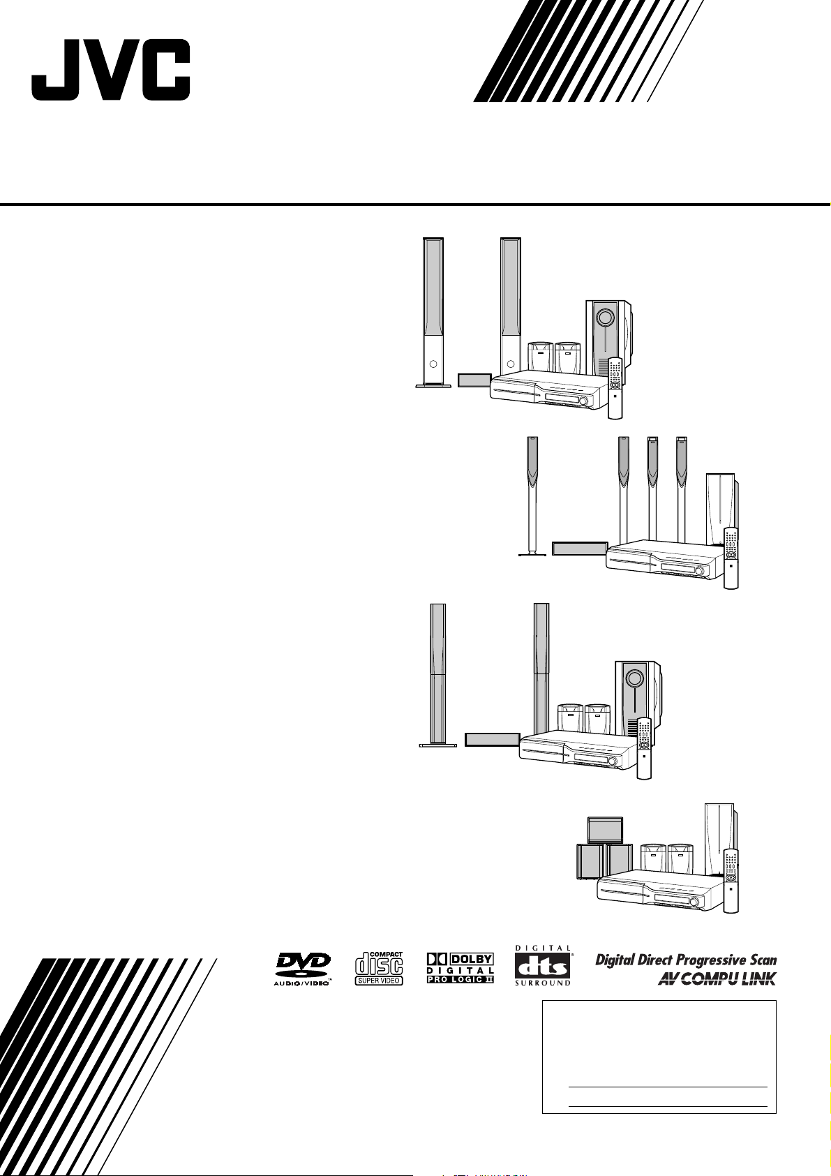
DVD DIGITAL THEATER SYSTEM
TH-C7
Consists of XV-THC7, SP-PWC7,
SP-THC7F, SP-THC7C and SP-THC5S
TH-C6
Consists of XV-THC6, SP-PWC6,
SP-THC6F, SP-THC6C and SP-THC6S
TH-C5
Consists of XV-THC5, SP-PWC5,
SP-THC5F, SP-THC5C and SP-THC5S
TH-C4/TH-C3
Consists of XV-THC4, SP-PWC4,
SP-THC4F, SP-THC4C and SP-THC4S
Consists of XV-THC3, SP-PWC3,
SP-THC3F, SP-THC3C and SP-THC3S
INSTRUCTIONS
For Customer Use:
Enter below the Model No. and Serial
No. which are located either on the rear,
bottom or side of the cabinet. Retain this
information for future reference.
Model No.
Serial No.
GVT0150-001D
[J/C]
Page 2
Warnings, Cautions and Others/Mises en garde, précautions et
indications diverses
Note to CATV system installer:
This reminder is provided to call the CATV system installer’s
attention to Section 820-40 of the NEC which provides guidelines
for proper grounding and, in particular, specifies that the cable
ground shall be connected to the grounding system of the
building, as close to the point of cable entry as practical.
For Canada
CAUTION: TO PREVENT ELECTRIC SHOCK,
MATCH WIDE BLADE OF PLUG TO WIDE
SLOT, FULLY INSERT.
For Canada
THIS DIGITAL APPARATUS DOES NOT
EXCEED THE CLASS B LIMITS FOR RADIO
NOISE EMISSIONS FROM DIGITAL
APPARATUS AS SET OUT IN THE
INTERFERENCE-CAUSING EQUIPMENT
STANDARD ENTITLED “DIGITAL
APPARATUS,” ICES-003 OF THE
DEPARTMENT OF COMMUNICATIONS.
CAUTION!
To avoid personal injury or
accidentally dropping the unit, have
two persons unpack, carry, and install
the unit.
Pour le Canada
ATTENTION: POUR EVITER LES CHOCS
ELECTRIQUES, INTRODUIRE LA LAME LA
PLUS LARGE DE LA FICHE DANS LA BORNE
CORRESPONDANTE DE LA PRISE ET
POUSSER JUSQUAU FOND.
Pour le Canada
CET APPAREIL NUMERIQUE RESPECTE LES
LIMITES DE BRUITS RADIOELECTRIQUES
APPLICABLES AUX APPAREILS NUMIRIQUES
DE CLASSE B PRESCRITES DANS LA NORME
SUR LE MATERIEL BROUILLEUR:
“APPAREILS NUMERIQUES”, NMB-003
EDICTEE PAR LE MINISTRE DES
COMMUNICATIONS.
ATTENTION!
Pour éviter toute blessure personnelle
ou toute chute accidentelle de
l’appareil, celui-ci doit être déballé,
transporté et installé par deux
personnes.
G-1
SP-THC7: 45 kg/100 lbs
TH-C6: 38 kg/84 lbs
TH-C5: 39 kg/86 lbs
TH-C4: 23.5 kg/52 lbs
TH-C3: 23.5 kg/52 lbs
SP-THC7:45kg/100lbs
TH-C6: 38 kg/84 lbs
TH-C5: 39 kg/86 lbs
TH-C4: 23.5 kg/52 lbs
TH-C3: 23.5 kg/52 lbs
Page 3
Warnings, Cautions and Others/Mises en garde, précautions et indications diverses
A
IMPORTANT FOR LASER PRODUCTS
1. CLASS 1 LASER PRODUCT
2.
CAUTION: Do not open the top cover. There are
no user serviceable parts inside the unit; leave all
servicing to qualified service personnel.
3.
CAUTION: Visible and invisible laser radiation
when open and interlock failed or defeated.
Avoid direct exposure to beam.
4. REPRODUCTION OF LABEL: CAUTION
LABEL, PLACED INSIDE THE UNIT.
CAUTION
To reduce the risk of electrical shocks, fire, etc.:
1. Do not remove screws, covers or cabinet.
2. Do not expose this appliance to rain or moisture.
IMPORTANT POUR PRODUITS LASER
1. PRODUIT LASER CLASSE 1
2.
ATTENTION: N’ouvrez pas le couvercle
supérieur. Il n’y a aucune pièce réparable par
l’utilisateur à l’intérieur de l’appareil; confiez
toute réparation à un personnel qualifié.
3.
ATTENTION: Risque de radiations laser visible
et invisible quand l’appareil est ouvert et que le
système de verrouillage ne fonctionne pas ou a
été mis hors service. Évitez toute exposition
directe au rayon.
4. REPRODUCTION DE L’ÉTIQUETTE:
ÉTIQUETTE DE PRÉCAUTION PLACÉE À
L’INTERIEUR DE L’APPAREIL.
TTENTION
Afin d’éviter tout risque d’électrocution, d’incendie, etc.:
1. Ne pas enlever les vis ni les panneaux et ne pas
ouvrir le coffret de l’appareil.
2. Ne pas exposer l’appareil à la pluie ni à l’humidité.
CAUTION — button!
( XV-THC7/ XV-THC6/ XVTHC5/ XV-THC4/ XV-THC3)
Disconnect the mains plug to shut the power off
completely (the STANDBY lamp goes off).
The button in any position does not disconnect
the mains line.
• When the system is on standby, the STANDBY
lamp lights red.
• When the system is turned on, the STANDBY
lamp goes off.
The power can be remote controlled.
CAUTION
(SP-PWC7/SP-PWC6/SPPWC5/SP-PWC4/SP-PWC3)
The power supply to the subwoofer is linked to the
center unit. The POWER ON lamp on the
subwoofer lights green when the power is turned on.
ATTENTION — Touche
( XV-THC7/ XV-THC6/ XVTHC5/ XV-THC4/ XV-THC3)
Déconnectez la fiche d’alimentation secteur pour
couper l’alimentation complètement (le témoin
STANDBY s’éteint).
La touche , dans n’importe quelle position, ne
déconnecte pas le système du secteur.
• Quand le système est en attente, le témoin
STANDBY est allumé en rouge.
• Quand le système est sous tension, le témoin
STANDBY s’éteint.
L’alimentation ne peut pas être télécommandée.
ATTENTION
(SP-PWC7/SP-PWC6/SPPWC5/SP-PWC4/SP-PWC3)
L’alimentation au caisson d’extrêmes graves passe
par l’unité centrale. Le témoin POWER ON vert sur
le caisson d’extrêmes graves s’allume quand le
système est allumé.
G-2
Page 4

Table of contents
Introduction ..................................... 2
Notes on handling .................................................................2
Supplied accessories ............................................................2
About discs ..................................... 3
Playable disc types ...............................................................3
Notes on file types ................................................................3
Description of parts and controls ... 4
Connections .................................... 7
Connecting the FM and AM antennas ....................................7
Connecting the satellite (front, center, surround) speakers ..... 8
Speaker layout ....................................................................12
Connecting a TV ..................................................................12
Connecting the powered subwoofer ....................................13
Connecting to an analog component ...................................13
Connecting to a digital component .....................................13
Connecting the power cord .................................................13
Operating external components with
the remote control ........................ 14
Operating the TV .................................................................14
Operating the DBS tuner or CATV converter .......................14
Operating the VCR ..............................................................15
Playback ........................................ 20
Basic playback ....................................................................20
One Touch Replay ...............................................................22
Fast-forward/fast-reverse search ........................................22
Skip to the beginning of a desired selection .......................22
Locating a desired title/group using number buttons .........23
Playing back a bonus group ................................................23
Selecting the desired title/playlist from the control display .23
Advanced operations .................... 24
Using the surround mode ...................................................24
Using the on-screen bar .....................................................25
Playing from a specified position on a disc .........................27
Using the file control display ..............................................28
Resume Playback ...............................................................29
Selecting a view angle .........................................................29
Selecting the subtitle ..........................................................29
Selecting the audio .............................................................30
Special picture playback .....................................................30
Program Playback ...............................................................32
Random Playback ...............................................................33
Repeat Playback .................................................................33
Tray lock .............................................................................34
Sound and other settings ....................................................35
Basic operations ........................... 16
Turning the system on/off ...................................................16
Selecting the source to play ................................................17
Adjusting the volume [VOLUME] ........................................17
Listening with headphones (not supplied) ..........................17
Turning off the sound temporarily [MUTING] .....................17
Adjusting the brightness of the indications [DIMMER] .......17
Sleep Timer [SLEEP] ...........................................................18
Adjusting the output level of the subwoofer and speakers ..18
Adjusting the treble sound [TREBLE] ..................................18
Adjusting the bass sound [BASS] .......................................18
Changing the scan mode ....................................................18
Optimizing the speaker settings [Smart Surround Setup] ...19
Setting DVD preferences .............. 36
Using the setup menus .......................................................36
Menu description ................................................................36
Tuner operations ........................... 39
Manual tuning .....................................................................39
Preset tuning ......................................................................40
Selecting the FM reception mode ........................................40
Reducing the noise of AM broadcast ..................................40
AV COMPU LINK remote control
system ........................................... 41
References .................................... 42
Maintenance .......................................................................42
Troubleshooting ..................................................................42
Specifications .....................................................................43
1
Page 5

Introduction
Notes on handling
7 Important cautions
Installation of the system
• Select a place which is level, dry and neither too hot nor too cold;
between 5°C and 35°C.
• Leave sufficient distance between the system and the TV.
• Do not use the system in a place subject to vibration.
Power cord
• Do not handle the power cord with wet hands!
• A small amount of power is always consumed while the power
cord is connected to the wall outlet (center unit only).
• When unplugging the power cord from the wall outlet, always
pull on the plug, not the power cord.
To prevent malfunctions of the system
• There are no user-serviceable parts inside. If anything goes
wrong, unplug the power cord and consult your dealer.
• Do not insert any metallic object into the system.
• Do not use any non-standard shape disc (like a heart, flower or
credit card, etc.) available on the market, because it may damage
the system.
• Do not use a disc with tape, stickers, or paste on it, because it
may damage the system.
7 Safety precautions
Avoid moisture, water and dust
Do not place the system in moist or dusty places.
Avoid high temperatures
Do not expose the system to direct sunlight and do not place it near
a heating device.
When you are away
When away on travel or for other reasons for an extended period of
time, disconnect the power cord plugs from the wall outlet.
Do not block the vents
Blocking the vents may damage the system.
Care of the cabinet
When cleaning the system, use a soft cloth and follow the relevant
instructions on the use of chemically-coated cloths. Do not use
benzene, thinner or other organic solvents including disinfectants.
These may cause deformation or discoloring.
If water gets inside the system
Turn the system off and disconnect the power cord plug from the
wall outlet, then call the store where you made your purchase.
Using the system in this condition may cause fire or electrical
shock.
Label sticker
Sticker
Paste
Note about copyright laws
Check the copyright laws in your country before recording from the
discs. Recording of copyrighted material may infringe copyright
laws.
Note about copyguard system
The discs are protected by copyguard system. When you connect
the system to your VCR directly, the copyguard system activates
and the picture may not be played back correctly.
Supplied accessories
Check to be sure you have all of the supplied accessories.
The number in parentheses is the quantity of the pieces supplied.
If anything is missing, contact your dealer immediately.
• Remote control (1)
• Batteries (2)
• FM antenna (1)
• AM loop antenna (1)
• Power cord (1)
• System cord (1)
• Composite video cord (1)
• Speaker cords (except for TH-C3)
For satellite (front left/right) and center speakers (3)
For satellite speakers (surround left/right) (2)
• Screws
TH-C7 (for satellite speakers):
M4 x 35 mm (8)
TH-C6 (for satellite speakers):
M5 x 25 mm (4)
M4 x 55 mm (12)
TH-C5 (for satellite speakers):
M4 x 40 mm (6)
• Bottom covers (for TH-C6 only)
For satellite speakers (front and surround) (4)
2
Page 6
About discs
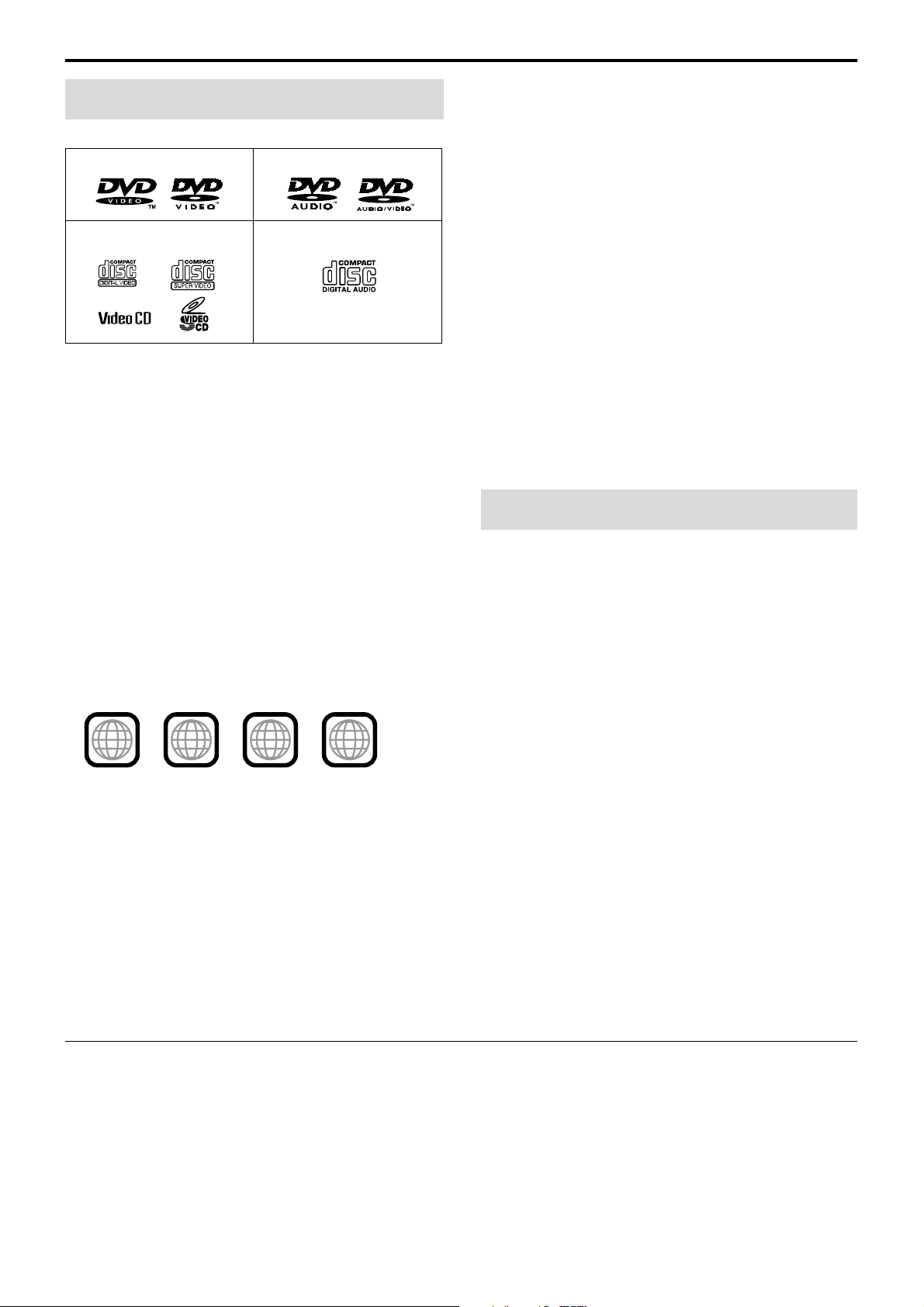
Playable disc types
This system has been designed to play back the following discs:
DVD VIDEO DVD AUDIO
VCD/SVCD Audio CD
• DVD Logo is a trademark of DVD Format/Logo Licensing
Corporation.
• The Non-DVD side of a “DualDisc” does not comply with the
“Compact Disc Digital Audio” standard. Therefore, the use of
Non-DVD side of a DualDisc on this product may not be
recommended.
• This system accommodates the NTSC system, and also can play
discs recorded with PAL system. Note that the PAL video signal
on a disc is converted to an NTSC signal and output.
• On some DVD VIDEOs, DVD AUDIOs, VCDs or SVCDs, their
actual operation may be different from what is explained in this
manual. This is due to the disc programming and disc structure,
not a malfunction of this system.
• Before playing back discs, read their instructions or cautions
carefully.
Region code of DVD VIDEO
This system can play back DVD VIDEO discs whose Region Code
numbers include the system’s Region Code, which is indicated on
the rear panel.
Example of playable DVD:
2
ALL
1
21
1
4
3
If a DVD with an improper Region Code number is loaded,
“REGION CODE ERROR!” appears on the TV screen and
playback cannot start.
Notes on DVD-R, DVD-RW and DVD-RAM
• This system can also play finalized DVD-Rs or DVD-RWs
recorded in DVD VIDEO format and DVD-RWs or DVD-RAMs
recorded in DVD VR format.
• This system can also play DVD-Rs or DVD-RWs if MP3, WMA,
and JPEG files are recorded on them with UDF Bridge format.
This system does not support “multi-border” discs.
Notes on CD-R and CD-RW
• This system can also play CD-Rs or CD-RWs if MP3, WMA and
JPEG files are recorded on them with ISO 9660 format.
• This system supports “multi-session” discs (up to 20 sessions).
• This system cannot play “packet write” discs.
Some discs may not be played back because of their disc
characteristics, recording conditions, or damage or stain on them.
Unplayable discs:
SACD, CD-I (CD-I Ready), Photo CD, etc.
Playing back these discs will generate noise and damage the
speakers.
Notes on file types
For all playable files
• The system can only recognize and play files with one of the
following extensions, which can be in any combination of upper
and lower case;
MP3: “.MP3”, “.mp3”
WMA: “.WMA” , “.wma”
JPEG: “.JPG”, “.JPEG”, “.jpg”, “.jpeg”
• The system recognizes up to 150 tracks (files) per group, 99
groups per disc, and the total number of the tracks (files) that the
system can play is 4000.
• Some files may not be played back normally because of their disc
characteristics or recording conditions.
For MP3/WMA files
• The system supports MP3/WMA files recorded with a bit rate of
32 – 320 kbps and a sampling frequency of 16 kHz, 22.05 kHz,
24 kHz*, 32 kHz, 44.1 kHz, or 48 kHz.
• If the tag information (album name, artist, and track title, etc.) is
recorded on a disc, it appears in the file control display on the TV
screen. (A pg. 28)
• We recommend to record each piece of material (song) at a
sample rate of 44.1 kHz and at a data transfer rate of
128 (96*) kbps.
* For WMA only
For JPEG files
• We recommend to record a file at 640 x 480 resolution.
• This system can only play baseline JPEG files.
This product incorporates copyright protection technology
that is protected by U.S. patents and other intellectual
property rights. Use of this copyright protection technology
must be authorized by Macrovision, and is intended for
home and other limited viewing uses only unless otherwise
authorized by Macrovision. Reverse engineering or
disassembly is prohibited.
3
Page 7
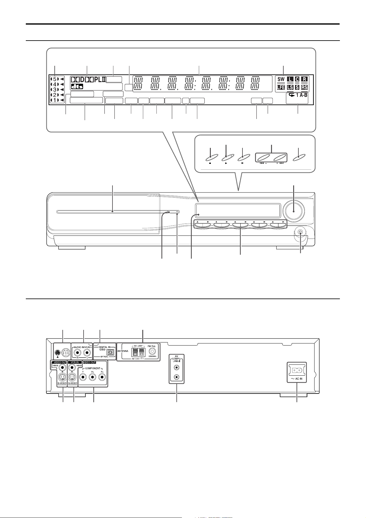
Description of parts and controls
Front panel (center unit)
Display window
pg. 22
pg. 25
pg. 39
pg. 40
pg. 21
pg. 25
FM AM
P L PCM SURR
WMA
MP3 RESUME
PROGRESSIVE B.S.P. CHAP. TRK PG PL BONUS ST PRG RND DISC ALL
pg. 18
pg. 29
pg. 31
pg. 21
CH
pg. 21
pg. 21
pg. 21
pg. 23
MONO
pg. 39
pg. 40
pg. 22
pg. 20
pg. 20, 22
Disc tray (inside): pg. 20
pg. 16
pg. 20
pg. 16
Remote sensor:
MHz
kHz
pg. 33
pg. 32
pg. 22
//
pg. 6
pg. 33
pg. 17
SOURCETUNING
pg. 17
DISC 5DISC 4DISC 3DISC 2DISC 1
pg. 17
Rear panel (center unit)
pg. 13
pg. 12
pg. 13
pg. 13
pg. 13
pg. 12
pg. 7
pg. 41
pg. 13
4
Page 8
Description of parts and controls
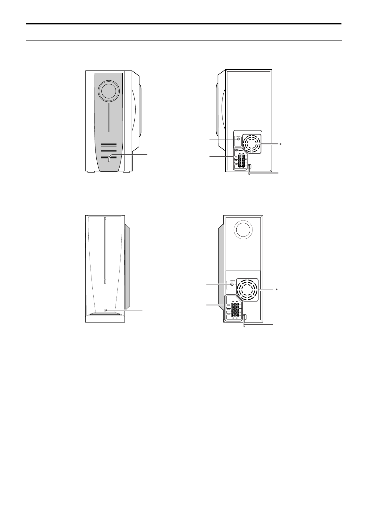
Powered subwoofer
SP-PWC7/SP-PWC5
Note that the illustration below is for SP-PWC5.
Front Rear
POWER ON
lamp:
pg. 16
pg. 13
pg. 11
3Ω16
Ω
Power c ord:
pg. 13
SP-PWC6/SP-PWC4/SP-PWC3
pg. 13
pg. 11
POWER ON lamp:
pg. 16
Front
NOTE
• For safety reasons, always ensure that there is sufficient space behind the powered subwoofer.
* Do not block the ventilation openings.
CAUTION:
SPEAKER IMPEDANCE
Ω16Ω
4
Rear
Power cord:
pg. 13
5
Page 9
Description of parts and controls
TV/VIDEO
TOP MENU/PG
REC
MENU/PL
ON
SCREEN
DVD
MUTING
FM/AM VCR
TV
TV VOL CHANNEL AUDIO VOL
TUNING
F AUDIO
VCR/DBS
DBS
AUDIO
VCR/DBS
TV
TUNING
FM MODEMEMORY
ENTER
TITLE/GROUP
AUDIO
VFP
SUBTITLE
ANGLE
PAG E
SET UP
SURROUND
FRONT L FRONT R
LEVEL
S.WFR
TV RETURN
REPEAT
SETTING
SMART
S.SETUP
CENTER
PLAY MODE
ZOOM
FL DISPLAY DIMMER SLEEP RETURN
100+
CANCEL
SCAN MODE
TREBLE
BASS
SURR. RSURR. L
SLOW SLOW
DISC 1
DISC 3
DISC 2
DISC 4 DISC 5
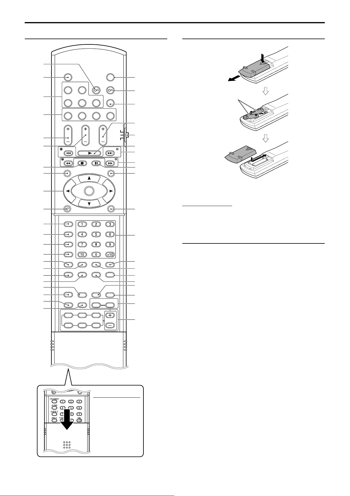
p
Remote control Putting batteries in the remote control
pg. 14
pg. 14
pg. 20
pg. 17
pg. 14
pg. 14
g. 20,
pg. 27
g. 18,
g. 15,
pg. 23
pg. 30
pg. 29
pg. 29
pg. 31
pg. 33
pg. 36
pg. 35
pg. 17
pg. 20
pg. 24
pg. 19
40
36
22
pg. 16
pg. 15
pg. 17
R6P (SUM-3)/AA (15F)
type dry-cell batteries
(supplied)
pg. 17
pg. 14 – 39
pg. 20
pg. 22, 39
pg. 22, 30
pg. 20, 40
pg. 27
If the range or effectiveness of the remote control decreases,
replace both batteries.
pg. 25
CAUTION
• Do not expose batteries to heat or flame.
Operating the system from the remote
Number
buttons:
pg. 22
pg. 32
pg. 32, 33
pg. 18, 31
pg. 31
pg. 18
pg. 27
pg. 18
control
Aim the remote control directly to the front panel of the center unit.
• Do not hide the remote sensor.
pg. 18
NOTE
• To use the buttons
under the cove r, slide
down the cover.
6
Page 10
Connections
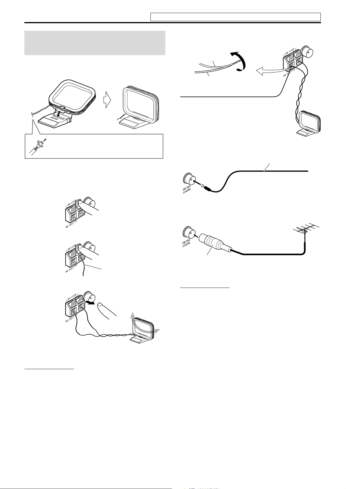
Connecting the FM and
AM antennas
7 AM loop antenna
Setting up supplied AM loop antenna
Do not connect the power cord until all other connections have been made.
If reception is poor
Center unit
AM loop antenna
Outdoor single vinyl-covered wire antenna
(not supplied)
If the antenna cord is covered with the insulation
coat, twist and pull the insulation coat off and
remove.
Connecting AM loop antenna
1
Center unit
2
3
Antenna cord
7 FM antenna
Center unit
If reception is poor
Center unit
Standard type (75 C
coaxial) connector
NOTE
• We recommend that you use coaxial cable for the FM antenna as it is
well-shielded against interference.
FM antenna (supplied)
Extend the supplied FM antenna
horizontally.
Outdoor FM antenna
(not supplied)
Outdoor FM antenna cord
(not supplied)
• Turn the loop antenna until you have the best reception during
AM broadcast program reception.
NOTE
• Make sure the antenna conductors do not touch any other terminals,
connecting cords and power cords. This could cause poor reception.
7
Page 11
Connections
Do not connect the power cord until all other connections have been made.
Connecting the satellite
(front, center, surround)
speakers
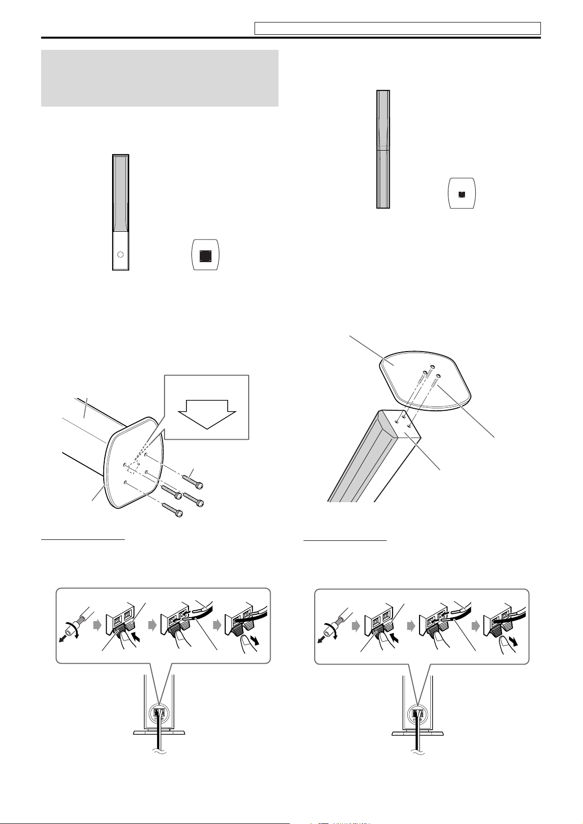
7 The front speakers — TH-C7
For the surround speakers of TH-C7, see “The surround speakers
— Except for TH-C6” (A pg. 10)
7 The front speakers — TH-C5
For the surround speakers of TH-C5, see “The surround speakers
— Except for TH-C6” (A pg. 10)
Front speaker
(x2)
Before assembling —
• Prepare a Phillips screwdriver (not supplied).
• Take care not to drop any component part while assembling;
otherwise, it may cause damage to the floor or injury.
Base plate
(x2)
1
Speaker (rear side)
Top of base plate
FRONT
Screw M4 x 35 mm
(supplied)
Front speaker
(x2)
Before assembling —
• Prepare a Phillips screwdriver (not supplied).
• Take care not to drop any component part while assembling;
otherwise, it may cause damage to the floor or injury.
Base plate
(x2)
1
Base plate
Screw M4 x 40 mm
Speaker (bottom)
(supplied)
Base plate
CAUTION
• NEVER insert your finger in between the speaker and the base plate,
as it may get hurt.
2
Red
Black
White
Black
CAUTION
• NEVER insert your finger in between the speaker and the base plate,
as it may get hurt.
2
Red
Black
White
Black
8
Page 12
Connections
Do not connect the power cord until all other connections have been made.
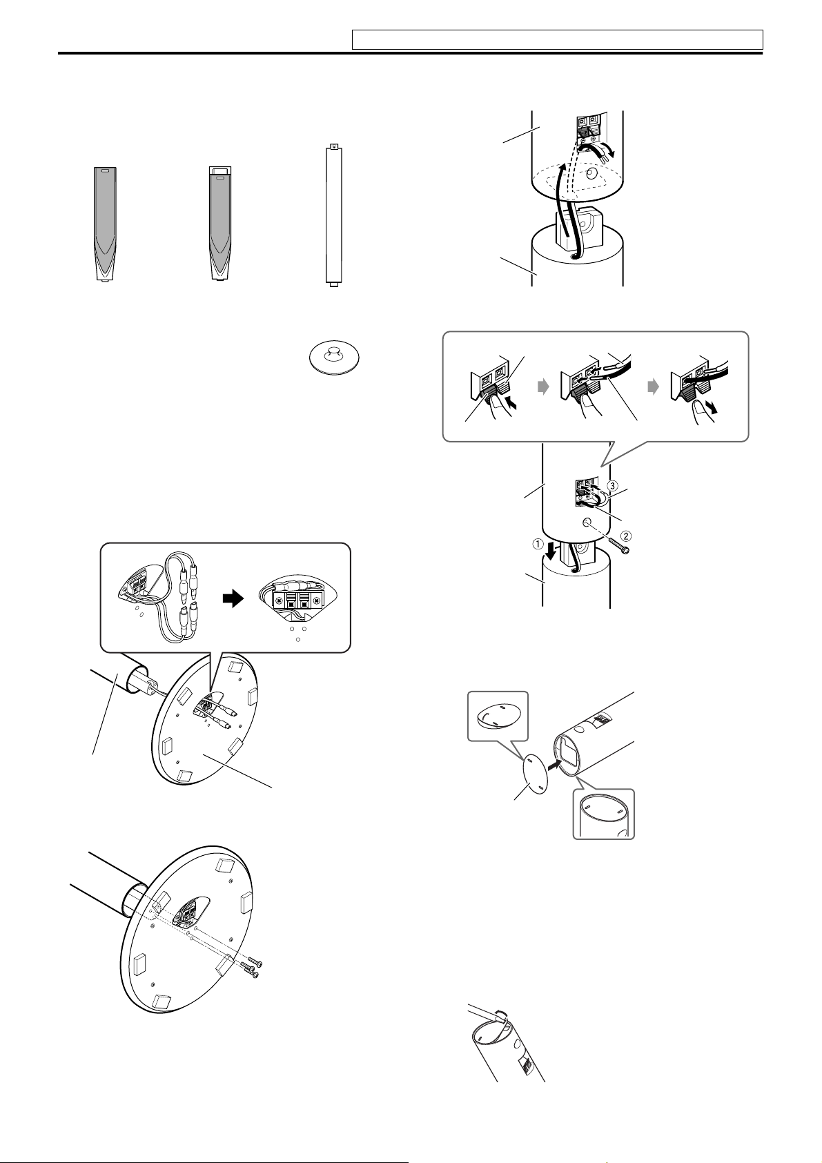
7 The front and surround speakers — TH-C6
The following procedure explains the front speaker assembly. The
assembly of both the front and surround speakers are done in the
same manner.
Front speaker
(×2)
Before assembling —
• Prepare a Phillips screwdriver (not supplied).
• Take care not to drop any component part while assembling;
otherwise, it may cause damage to the floor or injury.
Surround speaker
(×2)
Stand
(×4)
Base plate
(×4)
1
3
4
Speaker
Stand
Black
Speaker
Red
White
Black
White
Black
2
Stand
Base plate
Screw M4 x 55 mm
(supplied)
Stand
When installing the front and surround speakers on the
wall;
• Attach the supplied bottom cover on the bottom of each speakers
as illustrated.
Bottom
cover
• Be sure to have them installed on the wall by a qualified
personnel.
• DO NOT install the satellite speakers on the wall by yourself to
avoid unexpected damage from their falling off the wall due to
incorrect installation or weakness in wall structure.
• Care must be taken in selecting a location for speaker installation
on a wall. Injury to personnel or damage to equipment may result
if the speakers installed interfere with daily activities.
• If attaching the stand to the speaker, remove the bottom cover by
inserting a flat-pointed tool into the hole of the bottom cover.
Screw M5 x 25 mm
(supplied)
9
Page 13
Connections
Do not connect the power cord until all other connections have been made.
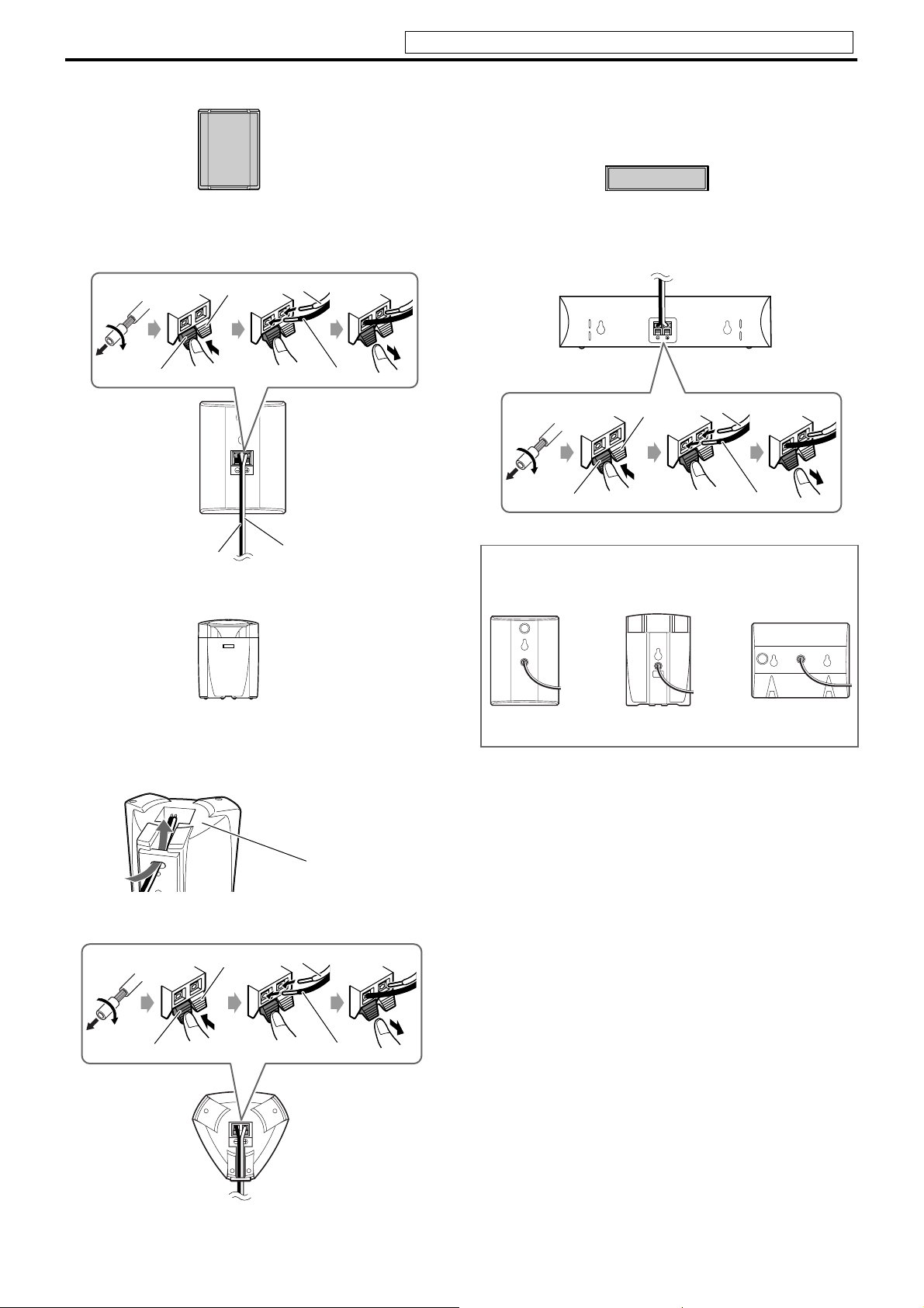
7 The front speakers — TH-C4
Front speaker
(×2)
Red
Black
White
Black
7 The center speaker
The following procedure explains SP-THC5C assembly. The
assembly of other center speakers is done in the same manner.
Center speaker
(×1)
Red
Black
White
Black
Black
7 The surround speakers
Surround speaker
(×2)
1
2
Red
White
— Except for TH-C6
Speaker
(bottom)
White
For TH-C3, the front, surround and center speakers are equipped
with their speaker cords attached directly to their speaker unit
instead of having speaker terminals on their cabinet.
Center speakerSurround speakerFront speaker
Black
Black
10
Page 14
Connections
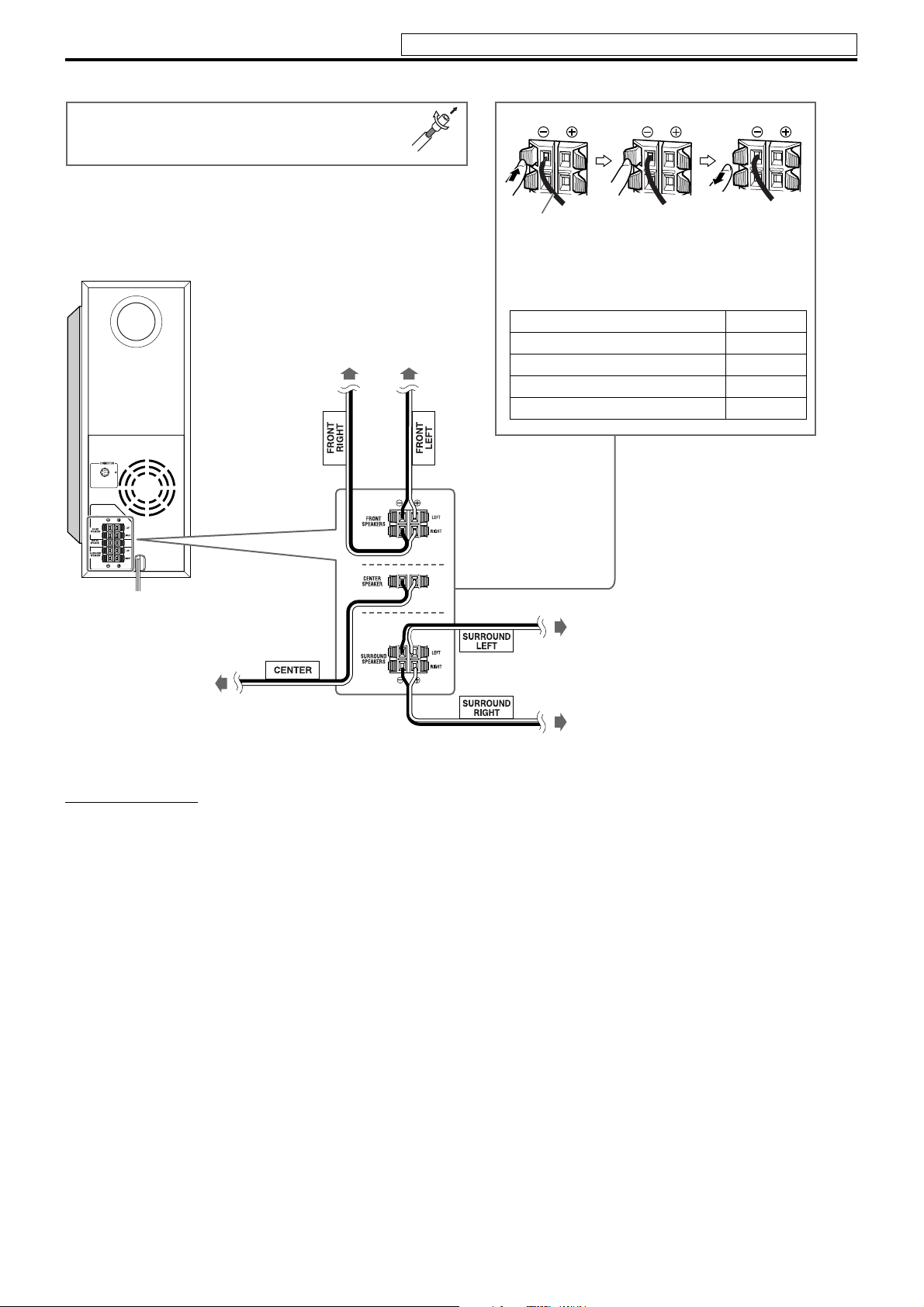
Note that the illustration below is for SP-PWC6.
Before connecting the speaker cords;
Twist and pull the insulation coat off and remove.
Powered subwoofer
TH-C7: SP-PWC7
TH-C6: SP-PWC6
TH-C5: SP-PWC5
TH-C4: SP-PWC4
TH-C3: SP-PWC3
Do not connect the power cord until all other connections have been made.
Front speakers
TH-C7: SP-THC7F
TH-C6: SP-THC6F
TH-C5: SP-THC5F
TH-C4: SP-THC4F
TH-C3: SP-THC3F
Speaker cord
• Connect the black cords to the black (r) terminals.
• Connect the white cords to the (q) terminals
referring to the table below:
FRONT SPEAKERS (LEFT) White
FRONT SPEAKERS (RIGHT) Red
CENTER SPEAKER Green
SURROUND SPEAKERS (LEFT) Blue
SURROUND SPEAKERS (RIGHT) Gray
CAUTION:
SPEAKER IMPEDANCE
Ω16Ω
4
Center speaker
TH-C7: SP-THC7C
TH-C6: SP-THC6C
TH-C5: SP-THC5C
TH-C4: SP-THC4C
TH-C3: SP-THC3C
CAUTION
• When you connect speakers other than the supplied ones, use
speakers of the same speaker impedance (SPEAKER IMPEDANCE)
indicated near the speaker terminals on the rear of the powered
subwoofer.
• DO NOT connect more than one speaker to one speaker terminal.
Surround speakers
TH-C7, TH-C5: SP-THC5S
TH-C6: SP-THC6S
TH-C4: SP-THC4S
TH-C3: SP-THC3S
Precautions for daily use
• When moving the speakers, do not pull the speaker cords;
otherwise, the speakers may fall over, causing damage or injury.
• Do not reproduce sounds at so high a volume that they are
distorted; otherwise, the speakers may be damaged by internal
heat buildup.
(For TH-C7, TH-C6 and TH-C5)
• When holding a speaker, always grasp the lower portion.
• Do not lean against the speakers, as the speakers could fall down
or break, possibly causing an injury. Especially be careful that
children do not lean against them.
11
Page 15
Connections
Do not connect the power cord until all other connections have been made.
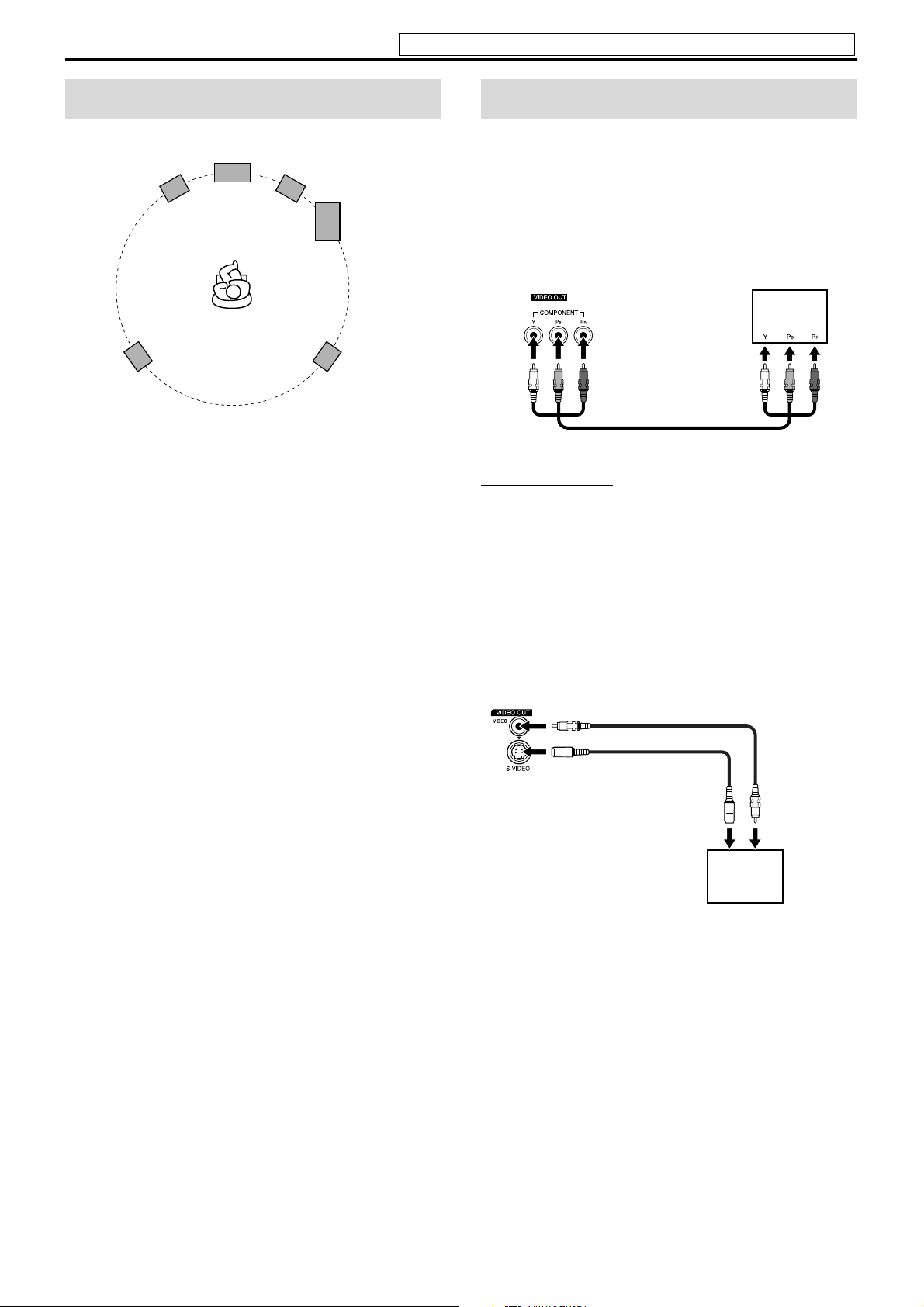
Speaker layout
Center speaker
Front left
speaker
Surround left
speaker
• Place the satellite speakers on a flat and level surface.
• The front and center speakers are magnetically shielded to avoid color
distortions on TVs. However, if not installed properly, they may
cause color distortions. So, pay attention to the following when
installing the speakers.
– When placing the speakers near a TV set, turn off the TV’s main
power switch or unplug it before installing the speakers. Then wait
at least 30 minutes before turning on the TV’s main power switch
again.
Some TVs may still be affected even though you have followed the
above. If this happens, move the speakers away from the TV.
• The surround speakers are not magnetically shielded.
If it is located nearby the TV or monitor, it will probably cause
color distortion on the screen. To avoid this, do not place the
speaker nearby the TV or monitor.
• Be sure to place the powered subwoofer to the TV’s right. If you place
the powered subwoofer to the TV’s left, keep sufficient distance
between them to prevent the TV screen from appearing mottled.
Front right
speaker
Powered
subwoofer
Surround right
speaker
Connecting a TV
• You can get better picture quality in the order — Component
video > S-video > Composite video.
• Distortion of picture may occur when connecting to the TV via a
VCR, or to a TV with a built-in VCR.
• You need to set “MONITOR TYPE” in the PICTURE menu
correctly according to the aspect ratio of your TV. (A pg. 37)
7 To connect a TV equipped with the component video
input jacks
Center unit
To component
video input
Component video cord (not supplied)
NOTE
• If your TV supports progressive video input, you can enjoy a high
quality picture by setting the progressive scan mode to active.
(A pg. 18)
• If the component video input jacks of your TV are of the BNC type,
use a plug adapter (not supplied) to convert the pin plugs to BNC
plugs.
• The component video signals can be output only when you select
“DVD” as the source to play. (A pg. 17)
7 To connect a TV equipped with the composite or S-
video jacks
Center unit
Align the 5 marks.
Composite video cord
(supplied)
or
S-video cord
(not supplied)
To S-video input
TV
To composite
video input
TV
12
Page 16
Connections
Do not connect the power cord until all other connections have been made.
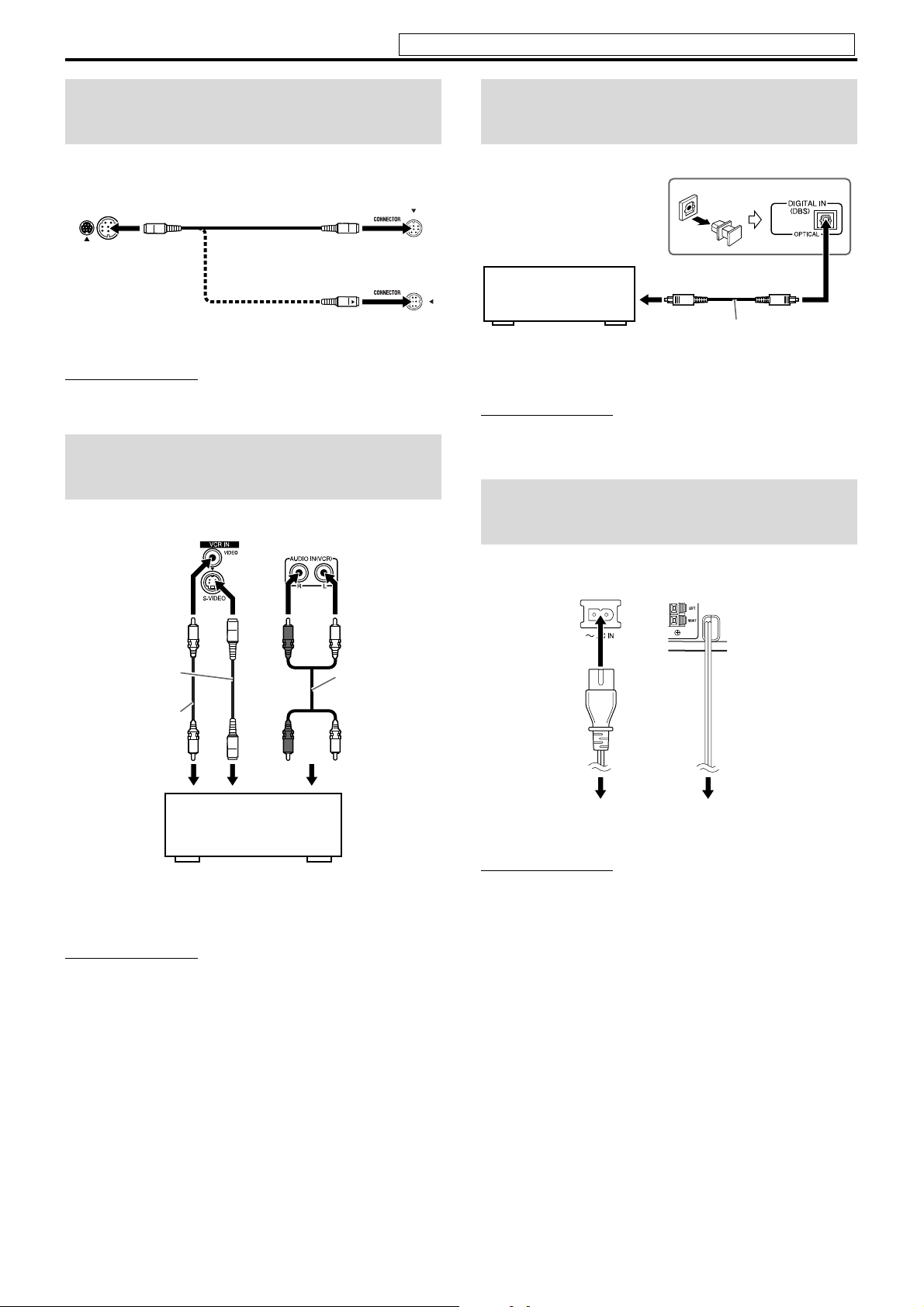
Connecting the powered
subwoofer
Powered
Center unit
Align the 5 marks.
NOTE
• The way of connecting the system cord varies depending on the type
of the powered subwoofer.
System cord
(supplied)
Align the 5 marks.
subwoofer
or
Connecting to an analog
component
You can enjoy the sound of an analog component.
Center unit
Connecting to a digital
component
You can enjoy the sound of a digital component.
Center unit
* tuner
DBS
MD player
* DBS = Direct Broadcasting Satellite
NOTE
• Only digital audio signals can be input when selecting “DBS” as the
source to play. (A pg. 17) When connecting a video component such
as a DBS tuner, operate this system to listen to the sound.
To digital optical output
Digital optical cord (not supplied)
Connecting the power
cord
Make sure that all other connections have been completed.
S-video cord
(not supplied)
or
Composite video
cord
(not supplied)
RCA pin plug
cord
(not supplied)
12 C
1 3 or 2 3)
VCR (
Cassette recorder (
TV (
C)
C)
A To composite video output
B To S-video output
C To audio output
NOTE
• The signals input to the VIDEO jack of the VCR IN jacks will be
output only from the VIDEO jack of the VIDEO OUT jacks, not from
the S-VIDEO jack of the VIDEO OUT jacks.
Center unit Powered
Power cord
(Supplied)
Plug into AC outlets.
CAUTION
• Disconnect the power cord before cleaning or moving the system.
• Do not pull on the power cord to unplug the cord. When unplugging
the cord, always grasp and pull the plug so as not to damage the cord.
subwoofer
Power cord
13
Page 17

Operating external components with the remote control
TV/VIDEO
REC
VCR
TV
TV VOL CHANNEL
VCR/DBS
DBS
VCR/DBS
TV
ENTER
TV RETURN
100+
The buttons described below are used on pages 14 and
15.
Remote control
mode selector
(play button)
Number
buttons
NOTE
• Manufacturers’ codes are subject to change without notice.
• Set the codes again after replacing the batteries of the remote control.
4 Press number buttons (1-9, 0) to enter
the manufacturer’s code (2 digits).
Examples:
For a Hitachi TV:
Press 1, then 0.
For a Toshiba TV:
Press 0, then 8.
Manufacturer Code Manufacturer Code
JVC 01 Samsung 12
Hitachi 10 Sharp 06
Magnavox 02 Sony 07
Mitsubishi 03 Toshiba 08
Panasonic 04, 11 Zenith 09
RCA 05
5 Release TV.
If there is more than one code listed for corresponding brand,
try each one until you enter the correct one.
7 Operation
Aim the remote control at the TV.
IMPORTANT
Before using the remote control to operate a TV;
• Set the remote control mode selector to TV.
The following buttons are available:
TV: Turns TV on and off.
TV VOL +/–: Adjusts the volume.
TV/VIDEO: Selects the input mode (either TV or
VIDEO).
CHANNEL +/–: Changes the channels.
1-10, 0, +10 (100+): Selects the channel.
TV RETURN: Alternates between the previously selected
channel and the current channel.
Operating the TV
7 To set the manufacturer’s code
You can operate a JVC TV without setting the manufacturer’s code.
1 Slide the remote control mode selector
to TV.
2 Press and hold TV.
Keep the button pressed until step 4 is finished.
3 Press ENTER.
Operating the DBS tuner
or CATV converter
7 To set the manufacturer’s code
1 Slide the remote control mode selector
to VCR/DBS.
2 Press DBS.
3 Press and hold F VCR/DBS.
Keep the button pressed until step 5 is finished.
4 Press ENTER.
14
Page 18

Operating external components with the remote control
See page 14 for button locations.
5 Press number buttons (1-9, 0) to enter
the manufacturer’s code (2 digits).
Examples:
For a GI Jerrold product:
Press 0, then 1.
For a Sony product:
Press 2, then 0.
Manufacturer Code
Echostar 21
GI Jerrold 01, 02, 03, 04, 05, 06, 07, 08
Hamlin 15, 16, 17, 18
Pioneer 13, 14
RCA 19
Scientific Atlanta 09, 10
Sony 20
Zenith 11, 12
6 Release F VCR/DBS.
If there is more than one code listed for your brand, try each
one until you enter the correct one.
7 Operation
Aim the remote control at the DBS tuner or CATV converter.
IMPORTANT
Before using the remote control to operate a
DBS tuner or CATV converter;
1 Set the remote control mode selector to
VCR/DBS.
2Press DBS.
The following buttons are available:
F VCR/DBS: Turns DBS tuner or CATV converter on and
off.
CHANNEL +/–: Changes the channels.
1-10, 0, +10 (100+): Selects the channel.
Operating the VCR
7 To set the manufacturer’s code
1 Slide the remote control mode selector
to VCR/DBS.
2 Press VCR.
3 Press and hold F VCR/DBS.
Keep the button pressed until step 5 is finished.
5 Press number buttons (1-9, 0) to enter
the manufacturer’s code (2 digits).
Examples:
For a Philips VCR:
Press 0, then 9.
For an NEC VCR:
Press 2, then 5.
Manufacturer Code Manufacturer Cod e
JVC 01, 02, 03 Philips 09
Emerson 11, 26 RCA 05, 06
Fisher 29 Samsung 24
Funai 10, 14, 15, 16 Sanyo 21, 22, 23
Gold Star 12 Sharp 27, 28
Hitachi 04 Shintom 30
Mitsubishi 13 Sony 18, 19, 20
NEC 25 Zenith 08
Panasonic 07, 17
6 Release F VCR/DBS.
If there is more than one code listed for your brand, try each
one until you enter the correct one.
7 Operation
Aim the remote control at the VCR.
IMPORTANT
Before using the remote control to operate a
VCR;
1 Set the remote control mode selector to
VCR/DBS.
2 Press VCR.
The following buttons are available:
F VCR/DBS: Turns VCR on and off.
3 (play button): Starts playback.
7 : Stops operation.
8 : Pauses playback.
y: Fast forwards video tape.
1: Rewinds video tape.
REC: Press this button together with 3 (play button) to
start recording or together with 8 to pause
recording.
CHANNEL +/–: Changes the TV channels on the VCR.
NOTE
When operating a VCR or DBS tuner/CATV converter;
• The source setting of VCR or DBS remains after you have changed
the remote control mode selector to AUDIO or TV. When operating
VCR or DBS tuner/CATV converter again, it is not necessary to press
VCR or DBS after setting the remote control mode selector.
4 Press ENTER.
15
Page 19

Basic operations
The buttons on the remote control are used to explain most of the
operations in this manual. You can use the buttons on the center
unit same as on the remote control for operations unless
otherwise noted.
IMPORTANT
Before using the remote control for the following
operation;
• Set the remote control mode selector to AUDIO.
The buttons described below are used on
pages 16 to 19.
Source
selecting
buttons
Remote control
mode selector
Cursor
(3/2/Y/5)/
ENTER
DIMMER SLEEP
SMART
S.SETUP
BASS
Speaker
buttons
FRONT L FRONT R
CENTER
S.WFR
SURR. RSURR. L
TREBLE
LEVEL
BASS/
LEVEL
Turning the system on/off
On the remote control:
Press AUDIO.
On the center unit:
Press .
When DVD is selected as the source (A pg. 17), the following
messages will appear on the TV screen.
• “OPEN”/“CLOSE”:
Appears when opening or closing the disc tray.
• “NOW READING”:
Appears when the system is reading the disc information.
• “REGION CODE ERROR!”:
Appears when the Region Code of the DVD VIDEO does not
match the code the system supports. The disc cannot be
played back.
• “NO DISC”:
Appears when no disc is loaded.
• “CANNOT PLAY THIS DISC”:
Appears when unplayable disc is loaded.
NOTE
• The STANDBY lamp turns on when the power is turned off and turns
off when the power is turned on.
• The power supply to the subwoofer is linked to the center unit. The
POWER ON lamp on the subwoofer lights green when the power is
turned on.
• A small amount of the power is consumed even when the power is
turned off (center unit only). This is called standby mode and the
STANDBY lamp lights in this mode. Unplug the power cord from the
AC outlet to turn the power off completely.
• You can also turn on the system by pressing the following buttons;
• One of 0 buttons on the center unit
• One of the source selecting buttons on the remote control
• One of the DISC (1-5) 3 buttons or 3 on the center unit
You can use the same buttons on the remote control.
SOURCE
DISC 5DISC 4DISC 3DISC 2DISC 1
16
Page 20

Basic operations
See page 16 for button locations.
Selecting the source to
play
On the remote control:
Press one of the source selecting buttons
(DVD, FM/AM, VCR or DBS).
DVD : To play back a disc (DVD VIDEO, VCD etc.). (A pg. 20)
FM/AM: To tune in an FM or AM station. (A pg. 39)
Each time you press the button, the band alternates
between FM and AM.
VCR: To select the source from a component connected to the
VCR IN jacks and AUDIO IN (VCR) jacks. (A pg. 13)
DBS: To select the source from a component connected to the
DIGITAL IN (DBS) jack. (A pg. 13)
On the center unit:
Press SOURCE repeatedly until the source
name you want appears on the display
window.
NOTE
• When AM, FM or DBS is selected, this system does not output video
signals.
• It may take time to change the source.
Listening with headphones
(not supplied)
CAUTION
Be sure to turn down the volume;
• Before connecting or putting on headphones as high volume may
damage both the headphones and your hearing.
• Before disconnecting headphones as high volume may be suddenly
output from the speakers.
While connecting a pair of headphones to the PHONES jack on the
center unit, the system automatically cancels the surround mode
(A pg. 24) currently selected, deactivates the speakers, turns the
subwoofer’s power off, and activates the headphone mode. “H.
PHONE” appears on the display window.
Headphone mode
When using the headphones, the following signals are output
regardless of your speaker setting;
• For 2 channel sources, the front left and right channel signals are
output from the headphones.
• Multi-channel signals are down-mixed and output from the
headphones.
• (For DVD AUDIO) When the disc prohibits down-mixing, only
the front left and right channels are output from the headphones.
In this case, “LR ONLY” appears on the display window for a
few seconds.
Adjusting the volume
[VOLUME]
CAUTION
• Always set the volume to minimum level before starting any source.
If the volume is set at its high level, the sudden blast of sound could
permanently damage your hearing and/or blow out the speakers.
On the remote control:
Press AUDIO VOL +/–.
On the center unit:
Turn VOLUME.
Turning off the sound
temporarily [MUTING]
Press MUTING.
To restore the sound
Perform one on the following:
• Press MUTING again.
• Press AUDIO VOL +/– (or turn VOLUME on the center unit).
Adjusting the brightness
of the indications
[DIMMER]
Press DIMMER.
Each time you press the button, the brightness level changes.
17
Page 21

Basic operations
See page 16 for button locations.
Sleep Timer [SLEEP]
The system turns off automatically when the specified period of
time has passed.
Press SLEEP.
Each time you press the button, the shut-off time changes.
Example:
minutes
SL
EE
To check the remaining time
Press SLEEP once.
To change the remaining time
Press SLEEP repeatedly.
To cancel
Press SLEEP repeatedly until “SLEEP – –” appears.
• Turning off the power also cancels the Sleep Timer.
60
P
Adjusting the output level
of the subwoofer and
speakers
Press each speaker button you want to
adjust the output level and then LEVEL +/–.
• FRONT L: Front Left speaker
• FRONT R: Front Right speaker
• SURR. L: Surround Left speaker
• SURR. R: Surround Right speaker
• CENTER: Center speaker
• S.WFR: Subwoofer
NOTE
• You can also make adjustments by using the setup menu shown on the
TV screen. (A pg. 37)
• The adjustments take effect for all sources.
Changing the scan mode
The system can be accommodated to your TV’s scan mode.
NOTE
• To use the system in PROGRESSIVE mode, it is required that the
center unit is connected to the TV by using a component video cord
(not supplied). (A pg. 12)
7 While DVD is selected as the source and stopped
1 Press and hold SCAN MODE for
2 seconds.
“INT-LACE” or “PROGRESS” appears on the display
window.
2 Press Cursor 3/2 to select the desired
mode.
• INT-LACE: Select this when your TV supports the
interlaced video input only.
• PROGRESS: Select this when your TV equipped with
component jacks supports the progressive
video input.
You can get better picture quality in PROGRESSIVE mode
than in INTERLACE mode.
3 Press ENTER while the selected mode
is displayed.
When “PROGRESS” is selected, the PROGRESSIVE
indicator lights on the display window.
NOTE
• Although the picture may be distorted when you press ENTER, this
is not a malfunction of the system.
• There are some progressive TVs and High-Definition TVs that are
not fully compatible with this system, resulting in an unnatural
picture when playing back a DVD VIDEO in the progressive scan
mode. In such a case, change the scan mode to “INT-LACE”.
To check the compatibility of your TV, contact your local JVC
customer service center.
• All JVC progressive TVs and High-Definition TVs are fully
compatible with this system.
Adjusting the treble
sound [TREBLE]
Press TREBLE and then LEVEL +/–.
NOTE
• The adjustments take effect for all sources.
Adjusting the bass sound
[BASS]
Press BASS and then LEVEL +/–.
NOTE
• The adjustments take effect for all sources.
18
Page 22

Basic operations
Optimizing the speaker
settings [Smart Surround
Setup]
NOTE
• When you change the positioning of the speakers or listener, or
replace the supplied speakers with other ones, perform Smart
Surround Setup again.
7 While DVD is selected as the source and stopped
1 Take your position where you listen to
the sound.
2 Press and hold SMART S. SETUP.
See page 16 for button locations.
When “FAILED !” appears on the TV screen
The system could not detect the clapping sound correctly. In such a
case, follow the instructions that appear on the TV screen.
• When the system detects the clapping sound as “FAILED !” three
times, set the delay time (DELAY) and the output level (LEVEL)
manually. (A pg. 37)
To cancel
Press SMART S. SETUP.
NOTE
• You need to set the subwoofer’s output level (LEVEL) manually.
(A pg. 18)
• In step 2, “SW ERROR” appears on the display window if the center
unit and the powered subwoofer are not connected correctly by using
the supplied system cord.
“SETTING” appears on the display window.
3 Clap your hands over your head once.
4 Make sure that “COMPLETED !”
appears on the TV screen, then press
SMART S. SETUP.
The system detects your clapping sound through the satellite
speakers, then automatically makes the best settings for each
speaker. “COMPLETED !” appears on the TV screen when
Smart Surround Setup completes.
19
Page 23

Playback
TOP MENU/PG MENU/PL
DVD
AUDIO
ENTER
TITLE/GROUP
FL DISPLAY
DISC 1
DISC 3
DISC 2
DISC 4 DISC 5
• The icon such as shows the disc formats or file types the
DVD
VIDEO
operation is available for.
IMPORTANT
Before using the remote control for the
following operation;
1 Set the remote control mode selector to
AUDIO.
2Press DVD .
The buttons described below are used on pages 20 to 23.
(play button)
Remote control
mode selector
TOP MENU/PG
MENU/PL
Basic playback
1 Press the desired DISC (1-5)
DVD
VIDEO
AUDIO
VR
DVD
DVD
0 on the center unit.
• The system turns on and the disc tray
comes out.
2 Place a disc.
When placing an 8 cm
Label side up
disc
2
C
S
I
D
1
C
S
I
D
2
C
S
I
D
1
C
S
I
D
3 Press DISC (1-5).
For MP3/WMA files
The file control display (A pg. 28) appears on the TV screen.
For JPEG files
Each file (still pictures) is shown on the TV screen for about 3
seconds (slide-show). When stopping playback, the file control
display (A pg. 28) appears on the TV screen.
For DVD VR disc
Pressing TOP MENU/PG or MENU/PL shows the control display
on the TV screen. (A pg. 23)
Number buttons
DISC 5DISC 4DISC 3DISC 2DISC 1
7 To pause playback
Press 8.
To return to playback, press 3 (play button).
7 To stop
Press 7.
7 On-screen guide icons
During DVD VIDEO playback, the following guide icons may
appear for a while on the TV screen;
• : appears at the beginning of a scene containing multisubtitle languages.
• : appears at the beginning of a scene containing multi-audio
languages.
• : appears at the beginning of a scene containing multi-angle
views.
• (Play), (Pause), / (Fast forward/
fast-reverse), / (Slow-motion forward/
reverse): appears when you perform each operation.
• : the disc cannot accept an operation you have tried to do.
20
Page 24

Playback
See page 20 for button locations.
NOTE
• Up to 5 discs can be loaded.
• You can also start playback by pressing 3 (play button) or DVD.
• The system plays back available discs sequentially until you stop
playback or until the disc loaded on the DISC 5 tray reaches to the
end. However, when DVD VIDEO or DVD AUDIO is loaded in the
system, playback of the disc next to the DVD VIDEO or DVD
AUDIO will not start.
• (For JPEG) The system cannot accept operations even though you
press any buttons before the entire picture appears on the TV screen.
• If you do not want the on-screen guide icons to appear, see page 38.
7 Playback information on the display window
DVD VIDEO
Example:
When a DVD VIDEO encoded with Dolby Digital 5.1ch is played
Chapter number
SURR
2
Signal and speaker indicators (A pg. 25)
Surround mode and digital signal format (A pg. 25)
Pressing FL DISPLAY
1
4
Elapsed playing time
(hour:minute:second)
3
::
3
2
1
MP3/WMA file
Example:
When an MP3 is played back
Track number
3
MP3
MP3 indicator
Pressing FL DISPLAY
MP3
*1
WMA indicator lights for WMA disc.
JPEG file
2
1
Elapsed playing time (minute:second)
*
Group number
2
1
G
File number
1
2
3
Signal and speaker
:
3
11
T
Track number
J
4
2
(during playback only)
2
3
1
G
E
P
indicators
Title number
T
SURR
DVD AUDIO
P LPCM
Track number Elapsed playing time
Pressing FL DISPLAY
Group number
P LPCM
VCD/SVCD/CD
Example:
When a CD is played back
1
1
G
Chapter number
2
C
5
2
::
1
3
4
Signal and speaker indicators
3
2
Track number
T
5
4
(hour:minute:second)
2
1
DVD VR disc
Example:
During playback on the Original program*
Pressing FL DISPLAY
Group number File number
G
1
Title number
22
PG
PG (Original program) indicator
Pressing FL DISPLAY
Title number
G
P
PG
F
2
Elapsed playing time
(hour:minute:second)
00::263
Chapter number
1C 3
3
1
2
Track number
LPCM
NOTE
• When a VCD or SVCD with PBC function is played, the elapsed
playing time does not appear, but “PBC” appears.
1
2
Elapsed playing time (minute:second)
Signal and speaker
3
3
:
1
indicators
21
Page 25

Playback
Example:
During playback on the Playlist*
Title number
3
PL (Playlist) indicator
Pressing FL DISPLAY
Playlist number
P
* Pressing TOP MENU/PG or MENU/PL, you can change the
play mode. (A pg. 23)
NOTE
• You can change the time information mode (except for MP3/WMA/
JPEG). (A pg. 26)
• You can also check the playback information on the TV screen.
(A pg. 25)
7 Disc information on the display window
The disc indicators on the display window show the current status
of the corresponding disc tray.
Example:
When the discs are loaded to disc trays 1, 2 and 5, and the disc in the
disc tray 5 is selected.
Elapsed playing time
(hour:minute:second)
0
00::503
PL
Chapter number
L
1C 1
PL
See page 20 for button locations.
Fast-forward/fast-reverse
search
7 During playback
On the remote control:
DVD
VIDEO
AUDIO
VR
DVD
DVD
Press y or 1.
Each time you press the button, the search speed
changes.
To return to normal speed playback
Press 3 (play button).
Press and hold x or 4.
Continuously pressing x or 4 increases the fast-forward/
reverse search speed.
NOTE
• The operation with x or 4 above is available for a disc other
than MP3 and WMA.
• When a DVD VIDEO, DVD VR, VCD and SVCD is played back, no
sound comes out during fast-forward/reverse search.
• When a DVD AUDIO or CD is played back, sound is intermittent and
low during fast-forward/reverse search.
• This feature may not work for some discs.
Skip to the beginning of a
desired selection
DVD
DVD
7 Using x/4 buttons
DVD
VIDEO
AUDIO
VR
Currently selected
disc number
Currently loaded disc number
7 Screen saver
A TV screen may burn out if a static picture is displayed for a long
time. To prevent this, the system automatically dims the screen if a
static picture is displayed for over 5 minutes (the screen saver
function).
• Pressing any button will cancel the screen saver function.
• If you do not want to use the screen saver function, see page 37.
One Touch Replay
You can move back the playback position by 10 seconds
from the current position.
7 During playback
On the remote control:
Press .
NOTE
• This function works in the same title.
• This function is not available during the repeat playback.
• This feature may not work for some discs.
DVD
VIDEO
DVD
VR
7 For DVD VIDEO/DVD VR (chapter):
During playback
For VCD/SVCD (track):
During playback without PBC function
For DVD AUDIO/CD/MP3/WMA/JPEG (track/file): During
playback or while stopped
Press x or 4 repeatedly.
NOTE
• When playing back an MP3/JPEG file, you can make operations
using the file control display. (A pg. 28)
• This feature may not work for some discs.
7 Using number buttons on the remote control
7 For DVD VIDEO/DVD VR (title, chapter):
While stopped, the title number is selected.
During playback, the chapter number is selected.
For DVD AUDIO (track):
During playback or while stopped
For VCD/SVCD (track):
During playback without PBC function
For CD/MP3/WMA/JPEG (track/file):
During playback or while stopped
Press number buttons (0-10, +10) to select
the desired number.
• For details on using the number buttons, see “How to use the
number buttons” below.
How to use the number buttons
To select 3: Press 3.
To select 14: Press +10, then 4.
To select 24: Press +10 twice, then 4.
To select 40: Press +10 three times, then 10.
Or press +10 four times, then 0.
22
Page 26

Playback
See page 20 for button locations.
Locating a desired title/
group using number
buttons
7 During playback or while stopped
1 Press TITLE/GROUP.
“_ _” or “_” is shown in the title/group
display area in the display window.
Example:
During DVD VIDEO playback
__
.
::
1
3
2
5
4
DVD
VIDEO
DVD
AUDIO
2 While the display window shows “_ _”
or “_”, use number buttons (0-10, +10)
to enter the desired title or group
number.
The system starts playback from the first chapter/track/file of
the selected title/group.
• For details on using the number buttons, see “How to use the
number buttons” (A pg. 22).
NOTE
• This feature may not work for some discs.
Playing back a bonus
group
Some DVD AUDIOs have a special group called “bonus
group” whose contents are not open to the public. The
bonus group is always assigned to the last group of a disc.
To play back a bonus group, you have to enter the specific “key
number” (a password). The way of getting the key number depends
on the disc. After getting the key number, you can play back the
bonus group by following the procedure below.
7 While the BONUS indicator lights up on the display window
DVD
AUDIO
1 Select the bonus group.
For selecting the group, see “Locating a desired title/group
using number buttons” described above.
The key number entry indication appears.
On the TV
Selecting the desired
title/playlist from the
control display
7 During playback or while stopped.
1 Press TOP MENU/PG or MENU/PL.
The control display is shown on the TV screen, and the system
starts playback of the first title/playlist.
• The PLAY LIST is shown only when the playlist is on the
DVD VR disc.
TOP MENU/PG: shows the ORIGINAL PROGRAM.
Example:
ORIGINAL PROGRAM
No Date Ch Time Title
1 25/04/04 4ch 19:00 JVC DVD World 2004
2 17/05/04 8ch 10:30
3 22/05/04 8ch 17:00 Music Festival
4 26/05/04 L-1 13:19 children 001
5 20/06/04 4ch 22:00
6 25/06/04 L-1 8:23 children 002
*1
*2
*3 *4
*1: Title number
*2: Recording date
*3: Recording source (TV station, the input terminal of the
recording equipment etc.)
*4: Start time of recording
*5: Title of the original program/playlist (The title may not be
displayed depending on the recording equipment.)
*6: Current title
MENU/PL: shows the PLAY LIST.
Example:
PLAY LIST
No Date Chap Length Title
1 25/05/04 001 1:03:16 My JVC World
2 17/06/04 005 1:35:25
3 20/06/04 003 0:10:23 Favorite music
4 25/06/04 001 0:07:19 children001-002
*8
*7
*9
*10 *5
*5
*6
*11
On the display window
_
KEY
BONUS
_
_
_
2 Press number buttons (0-9) to enter the
key number, then press ENTER.
When you enter the correct key number, playback starts and
the BONUS indicator goes off.
• If you enter the wrong number, reenter the correct number.
To clear the key number entry
Perform whichever one of the following:
• Open the disc tray.
• Turn off the system.
NOTE
• In Random Playback, tracks in the bonus group are not played back.
23
*7: Playlist number
*8: Creating date of playlists
*9: Number of chapters
*10: Total playing time
*11: Current playlist
2 Press Y/5 to select the desired title/
playlist.
The system starts playback of the selected title/playlist.
To clear the control display
• Press ENTER.
About the play mode on a DVD VR disc
• Original program (ORIGINAL PROGRAM):
The system can play back the original picture in the recorded
order.
• Playlist (PLAY LIST):
The system can play back the playlist edited by the recording
equipment.
Page 27

Advanced operations
• The icon such as shows the disc formats or file types the
DVD
VIDEO
operation is available for.
IMPORTANT
Before using the remote control for the following
operation;
• Set the remote control mode selector to AUDIO.
• There are exceptions in the operation mentioned
above. In such a case, follow each instruction.
The buttons described below are used on pages 24 to 35.
(play button)
AUDIO
Remote control
mode selector
/PG
TOP MENU/PG
SLOWSLOW
MENU/PL
SLOW
/
/PL
Cursor
(3/2/Y/5)/
ENTER
Number buttons
Using the surround mode
7 Auto Surround (AUTO SUR)
Used to reproduce the sound as it is recorded without any
conversion (downmixing or simulation, etc.). For example, a
multichannel source is automatically reproduced in multichannel
audio.
7 Dolby Surround
Dolby Pro Logic II*
Dolby Pro Logic II has a newly developed multichannel playback
format to decode all 2 channel sources — stereo source and Dolby
Surround encoded source — into a 5.1 channel.
Dolby Pro Logic II has two modes — Movie mode and Music
mode:
• Pro Logic II Movie (MOVIE)
Suitable for reproduction of Dolby Surround encoded sources
bearing the mark .
• Pro Logic II Music (MUSIC)
Suitable for reproduction of any 2 channel stereo music sources.
Dolby Digital*
Used to reproduce multichannel soundtracks of the software
encoded with Dolby Digital ( ).
7 DTS Digital Surround*
Used to reproduce multichannel soundtracks of the software
encoded with DTS Digital Surround ( ).
DTS Digital Surround (DTS) is another discrete multichannel
digital audio format available on CD and DVD software.
1
1
2
SURROUND
Available Surround modes for each input signal
The B marks show available surround modes.
Mode
Signal
Dolby D
(Multichannel)
Dolby D
(2 channel)
DTS Digital
Surround
(Multichannel)
DTS Digital
Surround
(2 channel)
Analog (VCR) or
Linear/Packed
PCM
(2 channel)
Linear/Packed
PCM
(Multichannel)
Surround
off
SURR OFF AUTO SUR MOVIE
Auto
Surround
Dolby Surround
3
*
MUSIC*
BB——B ————
BBBB————B
BB——— B ———
BB
BB————B
BBBB————B
BB——— — BB—
DOLBY
3
D
DTS Digital
Surround
DTS LPCM PPCM
Linear
PCM
Packed
PCM
DSP
ALL
ST
*1
Manufactured under
license from Dolby
Laboratories. “Dolby”,
3
*
“Pro Logic”, “MLP
Lossless”, and the
double-D symbol are
trademarks of Dolby
Laboratories.
*2
“DTS” and “DTS
Digital Surround” are
registered trademarks
of Digital Theater
Systems, Inc.
*3
You can select these
modes by pressing
SURROUND.
(A pg. 25)
24
Page 28

Advanced operations
See page 24 for button locations.
7 All Channel Stereo (DSP)
All Channel Stereo (ALL ST) mode can reproduce a larger stereo
sound field using all the connected (and activated) speakers.
All Channel Stereo can be used while reproducing 2 channel stereo
source.
Normal stereo sound All Channel Stereo
7 Indicators on the display window
Digital signal format indicators
PPCM, SURR: Lights when DVD AUDIO packed PCM signals
comes in.
LPCM, SURR: Lights when Linear PCM signal comes in.
GD, SURR: Lights when Dolby D signals come in.
C, SURR: Lights when DTS Digital (Surround) signals
come in.
No indication: No digital signal indicator lights when analog
signals come in.
Dolby Surround/DSP mode indicators
GPLII, SURR: Lights when Dolby Pro Logic II mode is
activated.
SURR: Lights when All Channel Stereo mode is
activated.
Source signal indicators, etc.
Light to indicate the incoming signals.
a: Lights when the left channel signal comes
in.
b: Lights when the center channel signal comes in.
c: Lights when the right channel signal comes in.
d: Lights when the LFE channel signal comes in.
g: Lights when the surround left channel signal comes in.
i: Lights when the surround right channel signal comes in.
h: Lights when the monaural surround channel signal or 2
channel Dolby Surround signal comes in.
SW : Always lights.
The channel with “” shows that the corresponding speakers are
reproducing the channels’ sound.
If the channels’ sound decoded into 5.1 channel is reproduced, only
“” lights.
7 When playing back digital multichannel software
(except during SURR OFF mode)
The appropriate multichannel surround mode (Dolby D, DTS
Digital Surround or Linear/Packed PCM) is automatically selected.
7 When playing back 2 channel source
You can select either mode of Dolby Pro Logic II (MOVIE/
MUSIC) or the DSP (ALL ST) mode.
Press SURROUND repeatedly to select the
desired mode.
The surround mode is turned on and the current surround mode
appears on the display window.
Each time you press the button, the surround mode changes.
For details on each mode, see page 24.
To turn off the surround mode
Press SURROUND repeatedly until SURR
OFF appears on the display window.
Storing adjustments — auto memory
When you turn the power off, the system memorizes the current
surround mode. The memorized mode is automatically recalled
when you turn the power on.
NOTE
• When FM or AM is selected as the source, you can select All Channel
Stereo (ALL ST) and SURR OFF mode.
• For a down-mixing prohibited DVD AUDIO disc, the system
continues to output multi-channel signals with “MULTI CH” shown
on the display window even if the surround mode is turned off during
playback. On the other hand, the system outputs only the front left and
right channel signals with “LR ONLY” shown on the display window
when you start playback with the surround mode having been set to
“SURR OFF” or “H. PHONE”.
Using the on-screen bar
You can check disc information and you can use some functions
using the on-screen bar.
Showing the on-screen bar
7 Whenever a disc is loaded
DVD
VIDEO
DVD
AUDIO
DVD
VR
Selecting the surround mode
The system is set up to automatically select the optimal surround
mode for input signal from digital multichannel software.
When playing back 2 channel source, you can select the desired
surround mode manually.
IMPORTANT
Before using the remote control for the following
operation;
• Set the remote control mode selector to AUDIO.
25
Press ON SCREEN.
Each time you press the button, the on-screen bar
changes as follows on the TV screen.
Example:
During DVD VIDEO playback
Dolby D
2/0 . 0ch
Dolby D
2/0 . 0ch
(The on-screen bar disappears)
(back to the beginning)
• The currently selected item shows green.
OFF
Page 29

Advanced operations
See page 24 for button locations.
7 Contents of the on-screen bar during playback
DVD VIDEO
Dolby D
2/0 . 0ch
DVD AUDIO
Dolby D
2/0 . 0ch
VCD
SVCD
CD
G Shows playback status.
: appears during playback.
/ : appears during fast forward/reverse.
/ : appears during playback in forward slow-motion/
reverse slow-motion.
: appears when paused.
: appears when stopped.
H Select this to change time information (F). See “Changing the
time information” below.
I Select this for Repeat Playback. (A pg. 33)
J Select this for time search function. (A pg. 28)
K Select this for chapter (for DVD VIDEO and DVD VR) or track
(for DVD AUDIO) search function. (A pg. 27)
L Select this to change audio language, channel, or stream.
(A pg. 30)
M Select this to change subtitle language and subpicture.
(A pg. 29)
N Select this to change view angle. (A pg. 29)
O Select this to change the page. (A pg. 31)
P Shows Playback Mode status.
PROGRAM: appears during Program Playback. (A pg. 32)
RANDOM: appears during Random Playback. (A pg. 33)
Changing the time information
You can change the time information in the onscreen bar on the TV screen and the display
window of the center unit.
7 During playback
DVD
VIDEO
DVD
AUDIO
DVD
VR
DVD VR disc
DVD-VR
A Shows disc type.
B Shows audio information.
C Shows disc number.
D Shows current title (for DVD VIDEO), group (for DVD
AUDIO) number or play mode (for DVD VR).
E Shows current chapter number (for DVD VIDEO and DVD VR)
or track number (for other type of discs).
F Shows time information. See “Changing the time information”.
Dolby D
2/0 . 0ch
PG 1
CHAP 3
ON
TOTAL 0 : 00 : 34
1 Press ON SCREEN twice.
The on-screen bar appears on the TV screen.
2 Press Cursor 3/2 to highlight .
3 Press ENTER repeatedly to select the
desired information.
Example:
When elapsed playing time of disc is selected.
7 VCD/SVCD/CD
• TIME: Elapsed playing time of current track
• REM: Remaining time of current track
• TOTAL: Elapsed time of disc
• T. REM: Remaining time of disc
7 DVD VIDEO/DVD AUDIO/DVD VR
• TIME: Elapsed playing time of current chapter/track
• REM: Remaining time of current chapter/track
• TOTAL: Elapsed time of Title/Group/Program
• T. REM: Remaining time of Title/Group/Program
4 Press ON SCREEN.
The on-screen bar disappears.
NOTE
• When playing back DVD VR, “TIME” and “REM” cannot be shown.
26
Page 30

Advanced operations
Playing from a specified
position on a disc
You can start playing a title, chapter or track you specify. You can
also play a disc from specified time.
Locating a desired scene from the DVD
menu
DVD VIDEOs generally have their own menus which show
disc contents and you can display them on the TV screen.
You can locate a desired scene by using these menus.
7 Whenever a DVD VIDEO is loaded
DVD
VIDEO
1 Press TOP MENU/PG or MENU/PL.
The menu appears on the TV screen.
Example:
See page 24 for button locations.
2 Press number buttons (1-10, +10) to
select the number of the desired item.
• For details on using the number buttons, see “How to use the
number buttons” (A pg. 22).
To return to the menu
Press RETURN.
When “NEXT” or “PREVIOUS” is shown on the TV
screen:
• To go to the next page, press x.
• To return to the previous page, press 4.
NOTE
• If you want to play a PBC-compatible VCD/SVCD without using the
PBC function, perform any of the following:
• Start playback by pressing number buttons while stopped.
• Press x repeatedly until the desired track number is displayed,
then start playback by pressing 3 (play button).
The track number appears on the display window instead of
“PBC”.
• To activate the PBC function when playing a PBC-compatible VCD/
SVCD without using the PBC function, perform any of the following:
• Press TOP MENU/PG or MENU/PL.
• Press 7 twice to stop playback, then press 3 (play button).
Normally, a DVD VIDEO which contains more than one title
will have a “top” menu which lists the titles. Press
TOP MENU/PG to show the title menu.
Some DVD VIDEO may also have a different menu which is
shown by pressing MENU/PL.
See the instructions for each DVD VIDEO regarding its
particular menu.
2 Use Cursor 3/2/Y/5 to select a
desired item.
3 Press ENTER.
• With some discs, you can also select items by entering the
corresponding number using number buttons.
Locating a desired scene using a VCD/
SVCD menu with PBC
A VCD or SVCD recorded with PBC has its own
menus such as a list of contained songs. You can locate
a specific scene by using these menus.
7 During playback with PBC function
1 Press RETURN repeatedly until the
menu appears on the TV screen.
Example:
Locating a desired chapter/track using the
on-screen bar
7 During playback
1 Press ON SCREEN twice.
The on-screen bar appears on the TV screen.
DVD
VIDEO
DVD
AUDIO
DVD
VR
2 Press Cursor 3/2 to highlight /
.
3 Press ENTER.
Example:
During DVD VIDEO playback
Dolby D
2/0 . 0ch
4 Press number buttons (0-9) to enter the
desired chapter number.
Example:
To select 8: Press 8.
To select 10: Press 1, then 0.
To select 20: Press 2, then 0.
To select 37: Press 3, then 7.
To correct a misentry
Repeat step 4.
27
5 Press ENTER.
6 Press ON SCREEN.
The on-screen bar disappears.
NOTE
• You can select up to the 99th chapter/track.
Page 31

Advanced operations
See page 24 for button locations.
Locating a desired position by specifying
the time
7 For DVD VIDEO/DVD AUDIO/DVD VR:
During playback
For VCD/SVCD:
While stopped or during playback without PBC
function
For CD:
During playback or while stopped
DVD
VIDEO
7 When specifying the elapsed playing time from the
beginning of the disc
Perform the following procedure while stopped.
7 When specifying the elapsed playing time from the
beginning of the current title/track
Perform the following procedure during playback.
DVD
AUDIO
DVD
VR
1 Press ON SCREEN twice.
The on-screen bar appears on the TV screen.
2 Press Cursor 3/2 to highlight .
3 Press ENTER.
Dolby D
2/0 . 0ch
Using the file control
display
You can search and play desired groups and tracks/files
using the file control display on the TV screen.
Current group/total group
number
Tag information (for MP3/
WMA only)
Current group
Playback mode (PROGRAM,
RANDOM, REPEAT)
Elapsed playing time of current
track (for MP3/WMA only)
Current track (file)
4 Use number buttons (0-9) to enter the
time.
Example:
To play back from a point 2 (hours): 34 (minutes): 08 (seconds)
elapsed
Press 2 Press 3
Press 4
Press 8
To cancel a misentry
Press Cursor 2 repeatedly.
Press 0
5 Press ENTER.
6 Press ON SCREEN.
The on-screen bar disappears.
NOTE
• You can specify time in hours/minutes/seconds for DVD VIDEO/
DVD AUDIO/DVD VR and in minutes/seconds for VCD/SVCD/CD.
Current track (file) / total track
(file) number on current group
The file control display appears automatically during playback
(MP3/WMA) or while stopped.
7 For MP3/WMA:
During playback or while stopped
For JPEG:
While stopped
Total track (file)
number on disc
Playback status
1 Press Cursor 3/2/Y/5 to select the
desired group/track/file.
• For MP3/WMA, playback starts from the selected track.
2 Press 3 (play button) or ENTER.
• Track playback/slide-show starts from the selected track/
file.
• When you press ENTER for JPEG, only the selected file is
played back.
NOTE
• (For MP3/WMA) During playback, you can locate the desired track/
file by pressing x/4 or Cursor 5/Y.
• You can also check playback information on the display window.
(A pg. 21)
• Some group, track and file names may not be displayed correctly
depending on recording conditions.
• The order of groups, tracks and files may be displayed differently
from the order displayed on your personal computer.
28
Page 32

Advanced operations
See page 24 for button locations.
Resume Playback
When Resume Playback is set to “ON” (A pg. 38)
and you stop playback by the following operations,
the position where playback has been stopped is
stored. (“RESUME” appears on the display
window.)
• Turning off the power (A pg. 16)
• Pressing 7 once
• Changing the source (A pg. 17)
To start playback from the stored position
Press 3 (play button) or DVD.
• There may be a case where 3 (play button) does not work after
changing the source.
To clear the stored position
Press 7 again or open the disc tray with the playback disc.
DVD
VIDEO
DVD
AUDIO
DVD
VR
Selecting a view angle
7 During playback of a disc containing multi-view
angles
When using the ANGLE button:
DVD
VIDEO
DVD
AUDIO
1 Press ANGLE.
Example:
The first view angle is selected out of 3 view angles recorded.
Selecting the subtitle
7 During playback of a disc containing subtitles in
several languages
When using the SUBTITLE button:
DVD
VIDEO
DVD
AUDIO
DVD
VR
1 Press SUBTITLE.
Example (DVD VIDEO):
“ENGLISH” is selected out of 3 subtitle languages recorded.
2 Press Cursor Y/5 to select the desired
subtitle.
For DVD VR
• Pressing SUBTITLE activates the subtitles (subpictures)
regardless of whether the subtitles are recorded or not.
(subpictures will not change if no subpictures is recorded.)
For SVCD
• An SVCD can contain up to four subtitles. Pressing
SUBTITLE changes the subtitles regardless of whether the
subtitles are recorded or not. (Subtitles will not change if no
subtitle is recorded.)
NOTE
• To clear the subtitle, press SUBTITLE. Each time you press
SUBTITLE, subtitle appears and disappears alternately.
2 Press ANGLE repeatedly or press
Cursor Y/5 to select the desired view
angle.
When using the on-screen bar:
1 Press ON SCREEN twice.
The on-screen bar appears on the TV screen.
2 Press Cursor 3/2 to highlight .
3 Press ENTER.
Dolby D
2/0 . 0ch
4 Press Cursor Y/5 to select the desired
view angle.
5 Press ENTER.
6 Press ON SCREEN.
The on-screen bar disappears.
NOTE
• During DVD AUDIO playback, this feature is available only for the
video part.
When using the on-screen bar:
1 Press ON SCREEN twice.
The on-screen bar appears on the TV screen.
2 Press Cursor 3/2 to highlight .
3 Press ENTER.
Dolby D
2/0 . 0ch
4 Press Cursor Y/5 repeatedly to select
the desired subtitle.
5 Press ENTER.
6 Press ON SCREEN.
The on-screen bar disappears.
NOTE
• To clear the subtitle, press SUBTITLE. Each time you press
SUBTITLE, subtitle appears and disappears alternately.
• Some subtitle or audio languages are abbreviated in the pop-up
window. See “The language codes list” (A pg. 36).
• During DVD AUDIO playback, this feature is available only for the
video part.
29
Page 33

Advanced operations
See page 24 for button locations.
Selecting the audio
7 During playback of a disc containing audio in
several languages
When using the AUDIO button:
DVD
VIDEO
DVD
AUDIO
1 Press AUDIO.
Example (DVD VIDEO):
“ENGLISH” is selected out of 3 audio languages recorded.
2 Press AUDIO repeatedly or press
Cursor Y/5 to select the desired audio.
When using the on-screen bar:
1 Press ON SCREEN twice.
The on-screen bar appears on the TV screen.
2 Press Cursor 3/2 to highlight .
3 Press ENTER.
Dolby D
2/0 . 0ch
DVD
VR
Special picture playback
Frame-by-frame playback
7 During playback
Press 8 repeatedly.
Each time you press the button, the still picture
advances by one frame.
To return to normal playback
Press 3 (play button).
DVD
VIDEO
Playing back in slow-motion
7 During playback
1 Press 8 at the point where
you want to start playback in
slow-motion from.
The system pauses playback.
DVD
VIDEO
2 Press SLOW 9.
• Playback in forward slow-motion starts.
For DVD VIDEO/DVD AUDIO only:
• To play back in reverse slow-motion, press
Each time you press the button, the playback speed become
faster.
Example: On the TV
SLOW (.
DVD
AUDIO
DVD
AUDIO
DVD
VR
DVD
VR
4 Press Cursor Y/5 to select the desired
audio.
5 Press ENTER.
6 Press ON SCREEN.
The on-screen bar disappears.
NOTE
• Some subtitle or audio languages are abbreviated in the pop-up
window. See “The language codes list” (A pg. 36).
• “ST”, “L” or “R” is displayed when playing a VCD, SVCD or DVD
VR respectively representing “stereo”, “left sound” and “right
sound”.
To return to normal playback
Press 3 (play button).
NOTE
• Sound cannot be heard during slow-motion playback.
• During DVD AUDIO playback, this feature is available only for the
video part.
30
Page 34

Advanced operations
See page 24 for button locations.
Selecting browsable still picture recorded
on DVD AUDIO
Most DVD AUDIOs include browsable still pictures
(B.S.P.), which usually appear by turns automatically
during playback according to the playback sequence. You
can change the picture (turn the page) manually when the current
group/track has selectable pictures (pages).
7 During playback and while the B.S.P. indicator lights up on the
display window
When using the PAGE button:
Press PAGE repeatedly to select a desired
still picture.
When using the on-screen bar:
DVD
AUDIO
1 Press ON SCREEN twice.
The on-screen bar appears on the TV screen.
2 Press Cursor 3/2 to highlight .
3 Press ENTER.
Dolby D
2/0 . 0ch
NOTE
• The number of the magnification steps varies depending on the disc
type.
• During slide-show playback of JPEG, zooming in is not available. In
such a case, press 8 to pause slide-show playback, then zoom in.
• During DVD AUDIO playback, this feature is available only for the
video part.
• During playback, there may be a case where Cursor (3/2/Y/5)
does not work in step 2 above.
Changing the VFP setting
The VFP (Video Fine Processor) function enables
you to adjust the picture character according to the
type of programming, picture tone or personal
preference.
7 During playback
DVD
VIDEO
DVD
AUDIO
DVD
VR
1 Press VFP.
The current VFP settings appear on the TV screen.
Example:
4 Press Cursor 5/Y to select the desired
still picture.
5 Press ENTER.
6 Press ON SCREEN.
The on-screen bar disappears.
Zooming in
7 During playback or while paused
DVD
VIDEO
DVD
AUDIO
DVD
VR
1 Press ZOOM.
Each time you press ZOOM, scene
magnification changes.
2 While zoomed in, press Cursor 3/2/Y/
5 to move zoom-in area.
To return to normal playback
Press ZOOM repeatedly to select ZOOM OFF.
2 Press Cursor 3/2 repeatedly to select
the VFP mode.
• NORMAL: Normally select this.
• CINEMA: Suitable for movies.
When you select “NORMAL” or “CINEMA”, press VFP to
complete the setting.
• USER 1 and USER 2:
You can adjust parameters that affect picture
appearance.
Only when selecting “USER 1” or “USER 2” in step
2, proceed to perform the following operation;
3 Press Cursor Y/5 repeatedly to select
a parameter you want to adjust.
Adjust gradually and confirm picture appearance results are as
preferred.
• GAMMA:
Controls brightness of neutral tints while maintaining
brightness of dark and bright portions.
• BRIGHTNESS:
Controls screen brightness.
• CONTRAST:
Controls screen contrast.
• SATURATION:
Controls screen color depth.
• TINT:
Controls screen tint.
• SHARPNESS:
Controls screen sharpness.
31
Page 35

Advanced operations
See page 24 for button locations.
4 Press ENTER.
Example:
5 Press Cursor Y/5 to change the
setting.
6 Press ENTER.
The current VFP settings appear again.
7 Repeat steps 3 to 6 to adjust other
parameters.
8 Press VFP.
NOTE
• Although the setting display disappears in the middle of the
procedure, the setting at that time will be stored.
Program Playback
7 While stopped
DVD
VIDEO
DVD
AUDIO
1 Press PLAY MODE
repeatedly until program
window appears on the TV screen.
2 Follow the instructions that appear on
the TV screen to program the desired
chapters/tracks.
• For details on using the number buttons, see “How to use the
number buttons” (A pg. 22).
• The content’s numbers that you have to specify for
programming varies depending on the disc type:
• DVD VIDEO: Titles and chapters
• VCD, SVCD, CD: Tracks
• DVD AUDIO, MP3, WMA:
Groups and tracks
• Before you program the tracks in bonus group on a DVD
AUDIO, perform the procedure of “Playing back a bonus
group” (A pg. 23) to turn off the BONUS indicator on the
display window.
• You can specify the chapters/tracks whose number is up to
99.
• There may be a case that the group or title number can be
entered even for discs that contain no groups or titles. In
such a case, press ENTER to proceed to the Track/Chapter
column.
• When you press ENTER instead of the number buttons in
the Track/Chapter column, “ALL” appears and all the tracks
or chapters on the selected group or title are programmed as
a step.
To clear the programs one by one from the last
entered number
Press CANCEL repeatedly.
To clear all programs
Press 7.
You can also clear the program by turning off the system.
USE NUMERIC KEYS TO PROGRAM TRACKS.
USE CANCEL TO DELETE THE PROGRAM.
3 Press 3 (play button).
If all of the programmed tracks/files have been played back,
playback stops and the program window appears again. Note
that program setting remains.
To check the program contents
During playback, press 7. Playback stops and the program window
appears.
To quit the Program mode
While stopped, press PLAY MODE repeatedly until both program
window and disappear from the TV screen.
NOTE
• There may be a case where bonus group on a DVD AUDIO cannot be
played.
• The Resume function cannot be used with Program Playback.
• Program Playback may not work for some discs.
32
Page 36

Advanced operations
See page 24 for button locations.
Random Playback
You can play titles or tracks on a disc in random
order.
7 While stopped
DVD
VIDEO
DVD
AUDIO
1 Press PLAY MODE
repeatedly until
appears on the TV screen.
2 Press 3 (play button).
• When more than one discs are loaded, the system starts
Random Playback of the next disc after completing current
disc playback.
To quit Random mode
While stopped, press PLAY MODE repeatedly until both program
window and disappear from the TV screen.
You can also clear the Random mode by turning off the system.
NOTE
• The same title/track will not be played back more than once during
Random Playback.
Repeat Playback
Repeating the current selection or all
discs
7 For DVD VIDEO/DVD VR:
During playback
For VCD/SVCD:
During playback without PBC function or
stopped
For DVD AUDIO/CD/MP3/JPEG:
During playback or stopped
When using the REPEAT button:
Press REPEAT.
:
11
2
3
1
:
DVD
VIDEO
0
1
DVD
AUDIO
DVD
VR
Display
window
DISC
ALL
1
No
indication
NOTE
• When DVD VIDEO or DVD AUDIO is loaded in the system,
playback of the disc next to the DVD VIDEO or DVD AUDIO will
not start, although /REPEAT ALL on the TV screen or
ALL in the display window is shown.
• For DVD VIDEO and DVD AUDIO, REPEAT ALL and REPEAT
DISC may not be available depending on the disc.
When using the on-screen bar (except for MP3/
WMA/JPEG):
TV screen Meanings
Repeats the current group for
REPEAT GROUP
PG
PL
REPEAT ALL
,
REPEAT TRACK,
REPEAT STEP
,
REPEAT STEP
DVD AUDIO/MP3/WMA/
JPEG.
Repeats the current title for
DVD VIDEO.
(For DVD VR) Repeats the
current title for Original
program.
(For DVD VR) Repeats the
current playlist for Playlist.
Repeats all titles and tracks on
the current disc for DVD VR/
VCD/SVCD/CD/MP3/WMA/
JPEG.
Repeats all the available discs.
Repeats the current track for
DVD AUDIO/VCD/SVCD/
CD/MP3/WMA.
Repeats the current chapter for
DVD VIDEO/DVD VR.
Repeat mode is off.
The system plays back the disc
normally.
1 Press ON SCREEN twice.
The on-screen bar appears on the TV screen.
2 Press Cursor 3/2 to highlight .
Repeat mode indicator
Each time you press REPEAT, the Repeat mode changes.
33
3 Press ENTER.
Dolby D
2/0 . 0ch
4 Press Cursor Y/5 repeatedly to select
the Repeat mode.
5 Press ENTER.
6 Press ON SCREEN.
The on-screen bar disappears.
To cancel Repeat Playback
Select “OFF” in step 4.
Page 37

Advanced operations
Repeating a desired part [A-B Repeat]
You can repeat playback of a desired part by
specifying the beginning (point A) and ending
(point B).
7 During playback
DVD
VIDEO
DVD
AUDIO
DVD
VR
1 Press ON SCREEN twice.
The on-screen bar appears on the TV screen.
2 Press Cursor 3/2 to highlight .
See page 24 for button locations.
Tray lock
You can lock the tray and prohibit the unwanted disc ejection.
On the center unit ONLY:
While the system is turned off
DISC 1
3 Press ENTER.
Dolby D
2/0 . 0ch
4 Press Cursor Y/5 repeatedly to select
“A-B”.
5 Press ENTER at the beginning of the
part you want to repeat (point A).
Dolby D
2/0 . 0ch
6 Press ENTER at the end of the part you
want to repeat (point B).
A-B Repeat Playback starts.
7 Press ON SCREEN.
The on-screen bar disappears.
To cancel
Select “OFF” in step 4, then press ENTER.
NOTE
• When playing back a DVD VIDEO/DVD VR, A-B Repeat Playback
is possible only within the same title.
• “A-B” cannot be selected during Program and Random Playback.
Press and hold
• The system turns on and “LOCKED” appears on the display
window.
• If you try to eject the disc, “LOCKED” appears to indicate that
the tray is locked.
To cancel
Carry out the same operation again.
• The system turns on and “UNLOCKED” appears on the display
window.
34
Page 38

Advanced operations
Sound and other settings
IMPORTANT
Before using the remote control for the following
operation;
• Set the remote control mode selector to
AUDIO.
NOTE
Before you start operation;
• There is a time limit when doing the following steps. If the setting is
cancelled before you finish, start from step 1 again.
1 Press SETTING.
Example:
C.
A
E
D/M
C
P
2 Press Cursor Y/5 to select the item
you want to set.
• DEC (Decode):
When you play an external source (DBS is selected as a
source) that was encoded with Dolby D or DTS Digital
Surround, the following symptoms may occur;
• No sound comes out at the beginning of playback.
• Noise comes out while searching for or skipping chapters
or tracks.
A/PCM (Auto/PCM):
Normally select this. The system automatically
detects the incoming signals.
DD: Select this if the symptoms above occur when
playing a disc (or software) encoded with Dolby
D.
DTS: Select this if the symptoms above occur when
playing a disc (or software) encoded with DTS
Digital Surround.
• MON (Monitor Out):
Select the video output jack type by which you watch DVD
playback after connecting your TV. (A pg. 12)
Set the video output to use AV COMPU LINK remote
control system. (A pg. 41)
VIDEO: To watch DVD playback via the VIDEO jack.
S: To watch DVD playback via the S-VIDEO jack.
COMP (Component):
To watch DVD playback via the COMPONENT
VIDEO OUT jacks.
See page 24 for button locations.
3 Press Cursor 3/2 to make an
adjustment or selection.
Example:
C.
E
DDD
The adjustment is set and the display automatically disappears
a few seconds later.
NOTE
• When “DD” or “DTS” is selected, if a signal encoded with another
digital format comes in, you cannot listen to the sound. (The
GDIGITAL or C indicator flashes.)
35
Page 39

Setting DVD preferences
Using the setup menus
• You can change the language used in the setup menus. See
“Menu description” below.
Basic operation on the setup menus
IMPORTANT
Before using the remote control for the
following operation;
1 Set the remote control mode selector to
AUDIO.
2Press DVD .
Cursor
(3/2/Y/5)/
ENTER
7 While stopped
1 Press SET UP.
2 Follow the instructions that appear on
the TV screen.
Menu description
:Language menu (LANGUAGE)
7 MENU LANGUAGE
Some DVDs have their own menus in multiple languages.
• Select the initial language*.
7 AUDIO LANGUAGE
Some DVDs have multiple audio languages.
• Select the initial audio language*.
NOTE
• See the following “The language codes list” for the code of each
language, such as “AA”, etc.
The language codes list
AA Afar IK Inupiak RN Kirundi
AB Abkhazian IN Indonesian RO Rumanian
AF Afrikaans IS Icelandic RU Russian
AM Ameharic IW Hebrew RW Kinyarwanda
AR Arabic JI Yiddish SA Sanskrit
AS Assamese JW Javanese SD Sindhi
AY Aymara KA Georgian SG Sangho
AZ Azerbaijani KK Kazakh SH Serbo-Croatian
BA Bashkir KL Greenlandic SI Singhalese
BE Byelorussian KM Cambodian SK Slovak
BG Bulgarian KN Kannada SL Slovenian
BH Bihari KO Korean (KOR) SM Samoan
BI Bislama KS Kashmiri SN Shona
BN Bengali, Bangla KU Kurdish SO Somali
BO Tibetan KY Kirghiz SQ Albanian
BR Breton LA Latin SR Serbian
CA Catalan LN Lingala SS Siswati
CO Corsican LO Laothian ST Sesotho
CS Czech LT Lithuanian SU Sundanese
CY Welsh LV Latvian, Lettish SV Swedish
DA Danish MG Malagasy SW Swahili
DZ Bhutani MI Maori TA Tamil
EL Greek MK Macedonian TE Telugu
EO Esperanto ML Malayalam TG Tajik
ET Estonian MN Mongolian TH Thai
EU Basque MO Moldavian TI Tigrinya
FA Persian MR Marathi TK Turkmen
FI Finnish MS Malay (MAY) TL Tagalog
FJ Fiji MT Maltese TN Setswana
FO Faroese MY Burmese TO Tonga
FY Frisian NA Nauru TR Turkish
GA Irish NE Nepali TS Tsonga
GD Scots Gaelic NL Dutch TT Tatar
GL Galician NO Norwegian TW Twi
GN Guarani OC Occitan UK Ukrainian
GU Gujarati OM (Afan) Oromo UR Urdu
HA Hausa OR Oriya UZ Uzbek
HI Hindi PA Panjabi VI Vietnamese
HR Croatian PL Polish WO Wolof
HU Hungarian PS Pashto, Pushto VO Volapuk
HY Armenian PT Portuguese XH Xhosa
IA Interlingua QU Quechua YO Yoruba
IE Interlingue RM Rhaeto-Romance ZU Zulu
7 SUBTITLE
Some DVDs have multiple subtitle languages.
• Select the initial subtitle language*.
7 ON SCREEN LANGUAGE
• Select the language shown on the TV screen when operating this
system.
* When the language you have selected is not recorded to a disc,
the original language is automatically used as the initial
language.
36
Page 40

Setting DVD preferences
:Picture menu (PICTURE)
7 MONITOR TYPE
You can select the monitor type to match your TV when you play
DVDs recorded in the picture’s height/width ratio of 16:9.
• 16:9 (Wide television conversion)
Select this when the aspect ratio of your TV is fixed on 16:9
(wide TV).
When you play DVDs recorded in the picture’s height/width
ratio of 4:3, the system adjust the ratio of output signal
automatically.
• 4:3 LB (Letter Box conversion)
Select this when the aspect ratio of your TV is 4:3
(conventional TV). While viewing a wide screen picture, the
black bars appear on the top and the bottom of the screen.
• 4:3 PS (Pan Scan conversion)
Select this when the aspect ratio of your TV is 4:3
(conventional TV). While viewing a wide screen picture, the
black bars do not appear, however, the left and right edges of
the pictures will not be shown on the screen.
Ex.: 16:9 Ex.: 4:3 LB Ex.: 4:3 PS
NOTE
• Even if “4:3 PS” is selected, the screen size may become “4:3 LB”
with some DVDs. This depends on how DVDs are recorded.
7 PICTURE SOURCE
When you set the scan mode to “PROGRESS” (A pg. 18), you can
obtain optimal picture quality by selecting whether the content on
the disc is processed by frame (film source) or by field (video
source) .
Normally set to “AUTO”.
•AUTO
Used to play a disc containing both video and film source
materials.
This system recognizes the source type (video or film) of the
current disc according to the disc information.
• If the playback picture is unclear or noisy, or the oblique
lines of the picture are rough, try to change to other modes.
•FILM
Suitable for playing back a film source disc.
• VIDEO
Suitable for playing back a video source disc.
7 SCREEN SAVER (A pg. 22)
You can activate or deactivate Screen Saver function.
: Audio menu (AUDIO)
7 D. RANGE COMPRESSION
(Dynamic range compression)
You can enjoy low level recorded sound clearly at night even at a
low volume when listening to the sound with Dolby Digital.
•AUTO
Select this when you want to enjoy surround sound with its
full dynamic range (no effect applied).
•ON
Select this when you want to fully apply the compression
effect (useful at midnight).
NOTE
• When you play a multichannel Dolby Digital source with the
surround mode is off, the setting of D. RANGE COMPRESSION is
set to ON automatically.
: Speaker setting menu
(SPK. SETTING)
7 Level menu (LEVEL)
FRONT LEFT SPEAKER/FRONT RIGHT SPEAKER/
CENTER SPEAKER/SURROUND RIGHT SPEAKER/
SURROUND LEFT SPEAKER
While monitoring the test tone, adjust the center and surround
speakers volume as much as that of the front speakers.
TEST TONE*
Outputs the test tone.
* The test tone comes out of all of the activated speakers in the
following sequence:
s Front left speaker s Center speaker s Front right
speaker s Surround right speaker s Surround left
speaker s (back to the beginning)
7 Delay menu (DELAY)
Example:
Center
speaker
1 ms
Front left
0 ms
Subwoofer
Front right
0 ms
7 FILE TYPE
When several types of files are recorded on a disc, you can select
which files to play.
• AUDIO
Select this to play MP3/WMA files.
• STILL PICTURE
Select this to play JPEG files.
37
Surround left
2 ms
In this case, set the delay time of each speaker as follows;
• Delay time of front speakers: 0 ms
• Delay time of center speaker: 1 ms
• Delay time of surround speakers: 2 ms
FRONT LEFT SPEAKER/FRONT RIGHT SPEAKER/
CENTER SPEAKER/SURROUND RIGHT SPEAKER/
SURROUND LEFT SPEAKER
Adjust the distance from the listening position to the speakers.
Within the range from 0 ms to 15 ms. (by 1 ms)
Surround right
2 ms
Page 41

Setting DVD preferences
7 Subwoofer menu (SUBWOOFER)
LEVEL
You can set the output level of the subwoofer in the -6 dB to +6 dB
range.
CROSS OVER
The signals below the preset frequency level will be sent to and be
reproduced by the subwoofer.
Select one of the cross over frequency levels according to the bass
sound quality from the front/center/surround speakers.
:Other setting menu (OTHERS)
7 RESUME
You can activate or deactivate Resume Playback function.
(A pg. 29)
7 ON SCREEN GUIDE
You can activate or deactivate the on-screen guide icons.
(A pg. 20)
38
Page 42

Tuner operations
FM/AM
TUNING
AUDIO
TUNING
FM MODEMEMORY
IMPORTANT
Before using the remote control for the
following operation;
1 Set the remote control mode selector to
AUDIO.
2Press FM/AM.
NOTE
• When FM or AM is selected as the source, you can select All Channel
Stereo (ALL ST) and SURR OFF mode.
The buttons described below are used on pages 39 to 40.
Remote control
mode selector
Manual tuning
1 Press FM/AM repeatedly to select the
band.
Example:
When the system is tuned in to 810 kHz.
AM
0
8
1
kHz
2 Press TUNING 9/( repeatedly until
you find the frequency you want.
When you hold down the button until the system starts
searching for stations and then release it, the system stops
searching automatically when a station of sufficient signal
strength is tuned in to.
NOTE
• When an FM stereo program is received, the ST indicator lights on the
display window.
/
Number buttons
39
Page 43

Tuner operations
See page 39 for button locations.
Preset tuning
Once a station is assigned to a channel number, the station can be
quickly tuned in. You can preset 30 FM and 15 AM stations.
7 To preset the stations
1 Tune in the station you want to preset.
• If you want to store the FM reception mode for an FM
station, select the reception mode you want. See “Selecting
the FM reception mode” below.
Example:
When the system is tuned in to 103.5 MHz.
FM
103.50
MHz
2 Press MEMORY.
FM
While “CH” and “– –” are flashing:
_
_
CH
10
3
50
.
MHz
3 Press number button(s) (1-10, +10) to
select a preset number you want.
• For details on using the number buttons, see “How to use the
number buttons” (A pg. 22).
Example:
When the preset channel 1 is selected.
FM
1103.50
CH
MHz
Selecting the FM
reception mode
When the stereo FM program currently tuned in is noisy, you can
change the FM reception mode to improve the reception.
7 While listening to an FM station
Press FM MODE.
The FM reception mode appears on the display window.
Each time you press the button, the FM reception mode changes.
•AUTO:
When a program is broadcast in stereo, you will hear stereo
sound. (The ST indicator lights on the display window.) When in
monaural, you will hear monaural sound. This mode is also
useful to suppress static noise between stations.
• MONO:
Reception will be improved although you will lose the stereo
effect. (The MONO indicator lights on the display window.) In
this mode, you will hear noise until you are tuned in to a station.
Reducing the noise of AM
broadcast
When listening to an AM broadcast with a lot of noise interference,
you can change the Beat Cut mode to reduce the noise.
7 While listening to an AM station
Press FM MODE.
The current Beat Cut mode appears on the display window.
Each time you press the button, the Beat Cut mode changes.
• Choose “BEATCUT1” or “BEATCUT2” according to which
gives clearer sound.
If the setting is cancelled before you finish, start from step 2
again.
While the selected number is flashing:
4 Press MEMORY.
The selected number stops flashing.
The station is assigned to the selected preset number.
If the setting is cancelled before you finish, start from step 2
again.
5 Repeat steps 1 to 4.
• Storing a new station to a used number erases the previously
stored one.
7 To tune in to a preset station
1 Press FM/AM repeatedly to select FM or
AM.
2 Press number button(s) (1-10, +10) to
select a preset number.
• For details on using the number buttons, see “How to use the
number buttons” (A pg. 22).
NOTE
• You can also select a preset number by pressing y /1.
40
Page 44

AV COMPU LINK remote control system
The AV COMPU LINK remote
control system allows you to operate
JVC TVs and VCRs through the center unit. This system is
equipped with the AV COMPU LINK-III, which adds a function to
operate JVC’s video components via the video components
terminals. To use this remote control system, you need to connect
the video components you want to operate as follows.
• Refer also to the manuals supplied with your TV and video
components.
Connecting a TV and VCR
CAUTION
Before connecting;
• If you have already plugged your VCR, TV and the center unit into
the AC outlets, unplug their AC power cords first.
1 Connect the center unit to a TV and
VCR.
• For details, see page 12 and 13.
2 Connect the center unit to a TV and VCR
using the optional AV COMPU LINK
cords.
Center unit
AV COMPU LINK cord
(not supplied)
Available functions
The AV COMPU LINK remote control system allows you to use
the functions listed following.
One-touch video play
Simply by inserting a video cassette without its safety tab into the
VCR, you can enjoy video playback without manually setting other
switches. This system automatically turns on and changes the
source to VCR.
The TV automatically turns on and changes the input mode to the
appropriate position so that you can view the playback picture.
When you insert a video cassette with its safety tab in place, press
the play (3) button on the VCR or on the remote control to get the
same result.
One-touch DVD play
Simply by starting playback on the built-in DVD player, you can
enjoy playback without manually setting other switches. The TV
automatically turns on and changes the input mode to the
appropriate position so that you can view the playback picture.
Automatic selection of TV input mode
When you select DVD or VCR as the source to play on the system,
the TV automatically changes the input mode to the appropriate
position so that you can view the playback picture.
Automatic Power On/Off
The TV and VCR turn on and off along with the system.
When you turn on the system;
• If the previously selected source is “DVD”, only the TV will turn
on automatically.
• If the previously selected source is “VCR”, the TV and VCR will
turn on automatically.
When you turn off the system, the TV and VCR will turn off.
NOTE
• If you turn off the system while recording on the VCR, the VCR will
not turn off and will continue recording.
TV
VCR
3 Plug the AC power cords of the VCR, TV
and the center unit into the AC outlets.
4 Turn on the connected components
first, then turn on the center unit.
• When turning on the TV for the first time after the AV
COMPU LINK connection, turn the TV volume to
minimum using the TV volume control on the TV.
• When turning on the VCR, use the remote control supplied
with this system. (Press F VCR/DBS.)
NOTE
• To correctly use the automatic selection of TV input mode, select the
correct “MON” (Monitor Out) setting. (A pg. 35)
41
Page 45

References
To clean the disc
Maintenance
7 Handling Discs
• Remove the disc from its case by holding it at
the edge while pressing the center hole lightly.
• Do not touch the shiny surface of the disc or
bend the disc.
• Put the disc back in its case after use to
prevent warping.
• Be careful not to scratch the surface of the
disc when placing it back in its case.
• Avoid exposure to direct sunlight, temperature
extremes and moisture.
Troubleshooting
PROBLEM POSSIBLE CAUSE SOLUTION
Power does not come
on.
The remote control does
not work.
No sound. The system cord and/or speaker cord is not connected. Check the connection.
No picture is displayed
on the TV screen.
No picture is displayed
on the TV screen, the
picture is blurred, or the
picture is divided into
two parts.
Video and audio are
distorted.
The picture does not fit
the TV screen.
Hard to listen to
broadcast because of
noise.
The power cord and/or system cord is not connected. Connect the power cord and system cord correctly.
The batteries are exhausted. Replace the batteries. (A pg. 6)
Sunlight is falling directly on the remote sensor. Hide the remote sensor from direct sunlight.
The audio cord is not connected to AUDIO IN (VCR)
and/or DIGITAL IN (DBS) correctly.
An incorrect source has been selected. Select the correct source. (A pg. 17)
The decode mode is not set correctly. Select the proper decode mode. (A pg. 35)
The video cord is not connected correctly. Connect the cord correctly. (A pg. 12)
The disc is not playable. Use a playable disc. (A pg. 3)
The scan mode is set to “PROGRESS” though the
center unit is connected to the TV which does not
support the progressive video input such as a
conventional TV.
The disc is scratched or dirty. Replace or clean the disc.
A VCR is connected between the center unit and the
TV.
The monitor type is not set correctly. Set “MONITOR TYPE” properly. (A pg. 37)
Antennas are disconnected. Reconnect the antennas correctly and securely.
Wipe the disc with a soft cloth in a straight line
from center to edge.
• DO NOT use any solvent — such as
conventional record cleaner, spray,
thinner or benzine — to clean the disc.
7 Cleaning the system
• Stains on the system should be wiped off with a soft cloth. If the
system is heavily stained, wipe it with a cloth soaked in waterdiluted neutral detergent and wrung well, then wipe clean with a
dry cloth.
• Since the system may deteriorate in quality, become damaged or
get its paint peeled off, be careful about the following.
• DO NOT wipe it with a hard cloth.
• DO NOT wipe it strong.
• DO NOT wipe it with thinner or benzine.
• DO NOT apply any volatile substance such as insecticides to it.
• DO NOT allow any rubber or plastic to remain in contact with
it for a long time.
(A pg. 13)
Connect the cord correctly. (A pg. 13)
Change the scan mode to “INT-LACE”. (A pg. 18)
Connect the center unit and TV directly. (A pg. 12)
(A pg. 7)
42
Page 46

References
Specifications
7
Center unit
(XV-THC7/XV-THC6/XV-THC5/XV-THC4/XV-THC3)
Audio section
Total Harmonic Distortion 0.02 %
NOTE: This value is measured at System cord CONNECTOR for
reference.
Digital input*1:
DIGITAL IN (DBS): –21 dBm to –15 dBm
(OPTICAL) (660 nm E30 nm)
*1Corresponding to Linear PCM, Dolby Digital, and DTS Digital
Surround (with sampling frequency — 32 kHz, 44.1 kHz, 48 kHz)
Video section
Video System: NTSC
Horizontal Resolution: 500 lines
Signal-to-Noise Ratio: 64 dB
Video output level
Composite: 1.0 V(p-p)/75 C
S-video-Y: 1.0 V(p-p)/75 C
S-video-C: 0.286 V(p-p)/75 C
Component-Y: 1.0 V(p-p)/75 C
Component-P
Video input sensitivity/Impedance (VCR IN)
Composite: 1.0 V(p-p)/75 C
S-video-Y: 1.0 V(p-p)/75 C
S-video-C: 0.286 V(p-p)/75 C
Tuner section
Tuning Range
FM: 87.5 MHz to 108.0 MHz
AM: 530 kHz to 1 710 kHz
General
Power Requirements: AC 120 V , 60 Hz
Power Consumption: 16 W (at operation)
Dimensions (W M H M D):
Mass: 4.2 kg (9.3 lbs)
7 Subwoofer (SP-PWC7)
Amplifier section
Front/Center/Surround: 167 W per channel, RMS at 3 C at 1
Subwoofer: 167 W, RMS at 3 C at 100 Hz, with
Speaker section
Speaker unit: 25 cm (9-7/8 inches) Bass-reflex
Power Handling Capacity: 170 W
Impedance: 3 C
Frequency Range: 25 Hz to 200 Hz
General
Power Requirements: AC 120 V , 60 Hz
Power Consumption: 160 W (at operation)
Dimensions (W M H M D):
Mass: 16.5 kg (37 lbs)
B/PR: 0.7 V(p-p)/75 C
1.3 W (in standby mode)
400 mm M 85 mm M 399 mm
(15-3/4 inches M 3-3/8 inches M
15-3/4 inches)
kHz, with 10 % total harmonic
distortion.
10 % total harmonic distortion.
0 W (in standby mode)
264 mm M 481 mm M 459 mm
(10-7/16 inches M 18-15/16 inches M
18-1/8 inches)
7 Subwoofer (SP-PWC6)
Amplifier section
Front/Center/Surround: 167 W per channel, RMS at 3 C
at 1 kHz, with 10 % total harmonic
distortion.
Subwoofer: 167 W, RMS at 3 C at 100 Hz, with 10
% total harmonic distortion.
Speaker section
Speaker unit: 16 cm (6-5/16 inches) Bass-reflex
Power Handling Capacity: 170 W
Impedance: 3 C
Frequency Range: 30 Hz to 200 Hz
General
Power Requirements: AC 120 V , 60 Hz
Power Consumption: 160 W (at operation)
0 W (in standby mode)
Dimensions (W M H M D):
169 mm M 411 mm M 451 mm
(6-11/16 inches M 16-3/16 inches M
17-13/16 inches)
Mass: 11.5 kg (25.4 lbs)
7 Subwoofer (SP-PWC5)
Amplifier section
Front/Center/Surround: 167 W per channel, RMS at 3 C at 1
kHz, with 10 % total harmonic
distortion.
Subwoofer: 167 W, RMS at 3 C at 100 Hz, with
10 % total harmonic distortion.
Speaker section
Speaker unit: 25 cm (9-7/8 inches) Bass-reflex
Power Handling Capacity: 170 W
Impedance: 3 C
Frequency Range: 25 Hz to 200 Hz
General
Power Requirements: AC 120 V , 60 Hz
Power Consumption: 160 W (at operation)
0 W (in standby mode)
Dimensions (W M H M D):
264 mm M 481 mm M 459 mm
(10-7/16 inches M 18-15/16 inches M
18-1/8 inches)
Mass: 16.5 kg (37 lbs)
7 Subwoofer (SP-PWC4)
Amplifier section
Front/Center/Surround: 167 W per channel, RMS at 3 C at 1
kHz, with 10 % total harmonic
distortion.
Subwoofer: 167 W, RMS at 3 C at 100 Hz, with
10 % total harmonic distortion.
Speaker section
Speaker unit: 16 cm (6-5/16 inches) Bass-reflex
Power Handling Capacity: 170 W
Impedance: 3 C
Frequency Range: 25 Hz to 200 Hz
General
Power Requirements: AC 120 V , 60 Hz
Power Consumption: 160 W (at operation)
0 W (in standby mode)
Dimensions (W M H M D):
169 mm M 411 mm M 451 mm
(6-11/16 inches M 16-3/16 inches M
17-13/16 inches)
Mass: 11.5 kg (25.4 lbs)
43
Page 47

References
7 Subwoofer (SP-PWC3)
Amplifier section
Front: 140W per channel, RMS at 4 C at
1 kHz, with 10 % total harmonic
distortion.
Center/Surround: 130W per channel, RMS at 4 C at
1 kHz, with 10 % total harmonic
distortion.
Subwoofer: 140 W, RMS at 4 C at 100 Hz, with 10
% total harmonic distortion.
Speaker section
Speaker unit: 16 cm (6-5/16 inches) Bass-reflex
Power Handling Capacity: 140 W
Impedance: 4 C
Frequency Range: 30 Hz to 200 Hz
General
Power Requirements: AC 120 V , 60 Hz
Power Consumption: 135 W (at operation)
0 W (in standby mode)
Dimensions (W M H M D):
169 mm M 411 mm M 451 mm
(6-11/16 inches M 16-3/16 inches M
17-13/16 inches)
Mass: 11.5 kg (25.4 lbs)
7 Satellite Speakers — SP-XTHC7
Front speakers (SP-THC7F)
Speaker unit:
Woofer: 10 cm (3-15/16 inches) M 4
Tweeter: 4 cm (1-5/8 inches)
Bass-reflex, Magnetically Shielded
Power Handling Capacity: 170 W
Impedance: 3 C
Frequency Range: 60 Hz to 20 kHz
Dimensions (W M H M D):
270 mm M 1 085 mm M 310 mm
(10-11/16 inches M 42-3/4 inches M
12-1/4 inches)
Mass: 8.8 kg (19.4 lbs) each
Center speaker (SP-THC7C)
Speaker unit:
Woofer: 10 cm (3-15/16 inches) M 2
Tweeter: 4 cm (1-5/8 inches)
Bass-reflex, Magnetically Shielded
Power Handling Capacity: 170 W
Impedance: 3 C
Frequency Range: 65 Hz to 20 kHz
Dimensions (W M H M D):
380 mm M 141 mm M 163 mm
(15 inches M 4-9/16 inches M 6-7/16
inches)
Mass: 3.4 kg (7.5 lbs)
Surround speakers (SP-THC5S)
Speaker unit: 8.0 cm (3-3/16 inches)
Bass-reflex
Power Handling Capacity: 170 W
Impedance: 3 C
Frequency Range: 80 Hz to 20 kHz
Dimensions (W M H M D):
111.5 mm M 148 mm M 106.5 mm
(4-7/16 inches M 5-7/8 inches M
4-1/4 inches)
Mass: 0.44 kg (0.97 lbs) each
7 Satellite Speakers — SP-XTHC6
Front speakers (SP-THC6F)
Speaker unit: 5.5 cm (2-3/16 inches) M 2
1.5 cm (5/8 inches)
Bass-reflex, Magnetically Shielded
Power Handling Capacity: 170 W
Impedance: 3 C
Frequency Range: 90 Hz to 20 kHz
Dimensions (W M H M D):
250 mm M 1 104 mm M 250 mm
(9-7/8 inches M 43-1/2 inches M
9-7/8 inches)
Mass: 2.6 kg (5.8 lbs) each
Center speaker (SP-THC6C)
Speaker unit: 5.5 cm (2-3/16 inches) M 2
1.5 cm (5/8 inches)
Bass-reflex, Magnetically Shielded
Power Handling Capacity: 170 W
Impedance: 3 C
Frequency Range: 90 Hz to 20 kHz
Dimensions (W M H M D):
320 mm M 75 mm M 92 mm
(12-5/8 inches M 3 inches M 3-5/8
inches)
Mass: 0.9 kg (2.0 lbs)
Surround speakers (SP-THC6S)
Speaker unit: 5.5 cm (2-3/16 inches) M 2
1.5 cm (5/8 inches)
Bass-reflex
Power Handling Capacity: 170 W
Impedance: 3 C
Frequency Range: 90 Hz to 20 kHz
Dimensions (W M H M D):
250 mm M 1 142 mm M 250 mm
(9-7/8 inches M 45 inches M 9-7/8
inches)
Mass: 2.6 kg (5.8 lbs) each
44
Page 48

References
7 Satellite Speakers — SP-XTHC5
Front speakers (SP-THC5F)
Speaker unit: 5.5 cm (2-3/16 inches) M 2
Bass-reflex, Magnetically Shielded
Power Handling Capacity: 170 W
Impedance: 3 C
Frequency Range: 95 Hz to 20 kHz
Dimensions (W M H M D):
230 mm M 1 103.5 mm M 285 mm
(9-1/16 inches M 43-1/2 inches M
11-5/16 inches)
Mass: 3.5 kg (7.8 lbs) each
Center speaker (SP-THC5C)
Speaker unit: 5.5 cm (2-3/16 inches) M 2
Bass-reflex, Magnetically Shielded
Power Handling Capacity: 170 W
Impedance: 3 C
Frequency Range: 90 Hz to 20 kHz
Dimensions (W M H M D):320 mm M 75 mm M 92 mm
(12-5/8 inches M 3 inches M 3-5/8
inches)
Mass: 0.90 kg (2.0 lbs)
Surround speakers (SP-THC5S)
Speaker unit: 8.0 cm (3-3/16 inches)
Bass-reflex
Power Handling Capacity: 170 W
Impedance: 3 C
Frequency Range: 80 Hz to 20 kHz
Dimensions (W M H M D):
111.5 mm M 148 mm M 106.5 mm
(4-7/16 inches M 5-7/8 inches M
4-1/4 inches)
Mass: 0.44 kg (0.97 lbs) each
7 Satellite Speakers — SP-XTHC4
Front speakers (SP-THC4F)
Speaker unit: 8.0 cm (3-3/16 inches)
1.5 cm (5/8 inches)
Bass-reflex, Magnetically Shielded
Power Handling Capacity: 170 W
Impedance: 3 C
Frequency Range: 80 Hz to 20 kHz
Dimensions (W M H M D):
104.5 mm M 139 mm M 101 mm
(4-1/8 inches M 5-1/2 inches M 4
inches)
Mass: 0.56 kg (1.3 lbs) each
Center speaker (SP-THC4C)
Speaker unit: 8.0 cm (3-3/16 inches)
1.5 cm (5/8 inches)
Bass-reflex, Magnetically Shielded
Power Handling Capacity: 170 W
Impedance: 3 C
Frequency Range: 80 Hz to 20 kHz
Dimensions (W M H M D):
137 mm M 105 mm M 104.5 mm
(5-7/16 inches M 4-3/16 inches M
4-1/8 inches)
Mass: 0.57 kg (1.3 lbs)
Surround speakers (SP-THC4S)
Speaker unit: 8.0 cm (3-3/16 inches)
Bass-reflex
Power Handling Capacity: 170 W
Impedance: 3 C
Frequency Range: 80 Hz to 20 kHz
Dimensions (W M H M D):
111.5 mm M 148 mm M 106.5 mm
(4-7/16 inches M 5-7/8 inches M
4-1/4 inches)
Mass: 0.56 kg (1.3 lbs) each
7 Satellite Speakers — SP-XTHC3
Front speakers (SP-THC3F)
Speaker unit: 8.0 cm (3-3/16 inches)
1.5 cm (5/8 inches)
Bass-reflex, Magnetically Shielded
Power Handling Capacity: 140 W
Impedance: 4 C
Frequency Range: 80 Hz to 20 kHz
Dimensions (W M H M D):
104.5 mm M 139 mm M 101 mm
(4-1/8 inches M 5-1/2 inches M 4
inches)
Mass: 0.56 kg (1.3 lbs) each
Center speaker (SP-THC3C)
Speaker unit: 8.0 cm (3-3/16 inches)
1.5 cm (5/8 inches)
Bass-reflex, Magnetically Shielded
Power Handling Capacity: 140 W
Impedance: 4 C
Frequency Range: 80 Hz to 20 kHz
Dimensions (W M H M D):
137 mm M 105 mm M 104.5 mm
(5-7/16 inches M 4-3/16 inches M
4-1/8 inches)
Mass: 0.57 kg (1.3 lbs)
Surround speakers (SP-THC3S)
Speaker unit: 8.0 cm (3-3/16 inches)
Bass-reflex
Power Handling Capacity: 140 W
Impedance: 4 C
Frequency Range: 80 Hz to 20 kHz
Dimensions (W M H M D):
111.5 mm M 148 mm M 106.5 mm
(4-7/16 inches M 5-7/8 inches M
4-1/4 inches)
Mass: 0.56 kg (1.3 lbs) each
Designs & specifications are subject to change without notice.
45
Page 49

46
Page 50

For the U.S.A.
47
Page 51

TH-C7/TH-C6/
TH-C5/TH-C4/
TH-C3
DVD DIGITAL THEATER SYSTEM
EN
0105TMMMDWJEM© 2005 Victor Company of Japan, Limited
 Loading...