

Page 1
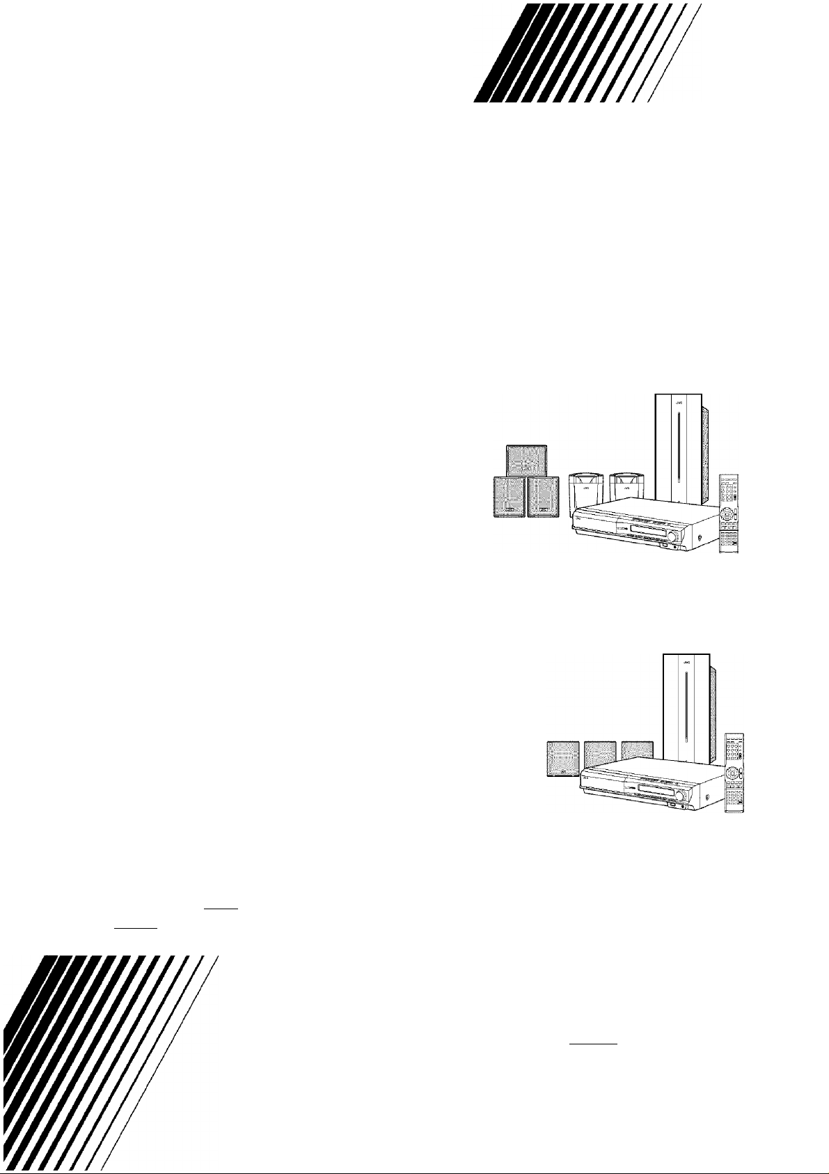
DVD DIGITAL THEATER SYSTEM
TH-C30
Consists of XV-THC30, SP-PWC30, SP-THC40F, SP-THC40C and SP-THC40S
TH-C20
Consists of XV-THC20, SP-PWC20, SP-THC20F, SP-THC20C and SP-THC20S
AU DIO/VIDEO
CGMF^CT
¡SUPER VIDEO I
□□IDOIBYI
DIGITAL
INSTRUCTIONS
DIGITAL
MPEG-4
SURROUND U l_ T R O
ASF PLAYBACK
Digital Direct Progressive Scan
At/^rstSDII I Iklir
For Customer Use:
Enter below the Model No. and Serial
No. which are located either on the rear,
bottom or side of the cabinet. Retain this
information for future reference.
Model No.__________________________
Serial No.
LVT1504-001A
[J]
Page 2
Warnings, Cautions and Others/Mises on garde, precautions et indications diverses
CAUTION
RISK OF ELECTRIC SHOCK
DO NOT OPEN
CAUTION: TO REDUCE THE RISK OF ELECTRIC SHOCK,
REFER SERVICING TO QUALIFIED SERVICE PERSONNEL
DO NOT REMOVE COVER (OR BACK).
NO USER SERVICEABLE PARTS INSIDE.
The lightning flash with arrowhead symbol,
within an equilateral triangle is intended to
alert the user to the presence of uninsulated
"dangerous voltage" within the product's
enclosure that may be of sufficient
magnitude to constitute a risk of electric
shock to persons.
The exclamation point within an equilateral
triangle is intended to alert the user to the
presence of important operating and
maintenance (servicing) instructions in the
literature accompanying the appliance.
WARNING; TO REDUCE THE RISK OF FIRE
OR ELECTRIC SHOCK, DO NOT EXPOSE
THIS APPLIANCE TO RAIN OR MOISTURE.
For U.S.A.
This equipment has been tested and found to comply with the
limits for a Class B digital device, pursuant to part 15 of the FCC
Rules. These limits are designed to provide reasonable
protection against harmful interference in a residential
installation.
This equipment generates, uses and can radiate radio frequency
energy and, if not installed and used in accordance with the
instructions, may cause harmful interference to radio
communications. However, there is no guarantee that
interference will not occur in a particular installation. If this
equipment does cause harmful interference to radio or television
reception, which can be determined by turning the equipment off
and on, the user is encouraged to try to correct the interference
by one or more of the following measures:
Reorient or relocate the receiving antenna.
Increase the separation between the equipment and receiver.
Connect the equipment into an outlet on a circuit different from
that to which the receiver is connected.
Consult the dealer or an experienced radio/TV technician for
help.
Note to CATV system Installer:
This reminder is provided to call the CATV system installer’s
attention to Section 820-40 of the NEC which provides guidelines
for proper grounding and, in particular, specifies that the cable
ground shall be connected to the grounding system of the
building, as close to the point of cable entry as practical.
CAUTION
Changes or modificatioiis not approved by JVC could void the
user’s authority to operate the equipment.
For Canada
THIS DIGITAL APPARATUS DOES NOT
EXCEED THE CLASS B LIMITS FOR RADIO
NOISE EMISSIONS FROM DIGITAL
APPARATUS AS SET OUT IN THE
INTERFERENCE-CAUSING EQUIPMENT
STANDARD ENTITLED “DIGITAL
APPARATUS,” ICES-003 OF THE
DEPARTMENT OF COMMUNICATIONS,
CAUTION! ATTENTION!
To avoid personal injury or Pour éviter toute blessure personnelle
accidentally dropping tiie unit, have ou tonte chute accidentelle de
two persons unpack, carry, and install l’appareil, ceiiii-ci doit être déballé,
the unit. transporté et installé par deux
TH-C30: 25 kg/56 lbs TH-C30: 25 kg/56 Ibs
TH-C20: 24 kg/53 lbs TH-C20: 24 kg/53 Ibs
Pour le Canada
GET APPAREIL NUMERIQUE RESPECTE LES
LIMITES DE BRUITS RADIOELECTRIQUES
APPLICABLES AUX APPAREILS
NUMIRIQUES DE CLASSE B PRESCRITES
DANS LA NORME SUR LE MATERIEL
BROUILLEUR: “APPAREILS NUMERIQUES”,
NMB-003 EDICTEE PAR LE MINISTRE DES
COMMUNICATIONS.
personnes.
•
1
.-A
m
G-1
Page 3

Warnings, Cautions and Others/Mises en garde, précautions et indications diverses
IMPORTANT FOR LASER PRODUCTS
1. CLASS 1 LASER PRODUCT
2. CAUTION; Do not open the top cover. There are
no user serviceable parts inside the unit; leave ail
servicing to qualified service personnel.
3. CAUTION: Visible and/or invisible class IM
laser radiation when open. Do not stare into
beam or view directly with optical instruments.
4. REPRODUCTION OF LABEL: CAUTION
LABEL, PLACED INSIDE THE UNIT.
CAUTION
VISIBLE AND/OR
INVISIBLE CLASS
1M LASER
RADIATION WHEN
OPEN. DO NOT
STARE INTO BEAM
OR VIEW ■ ■■
WITH OPTICAL
INSTRUMENTS.
VARNING
SYNLIG OCH/ELLER
OSYNUG .
LASERSTRÂLNING,
KLASS
Da. № OPPNAD. .
STIRRA EJ IN I sMeN
.....
HRECTLY OCK BET
........
BETRAKTA EJ
riCAL STRALEN
(ENGI
m. NAR D0ih
—--QpT^
AVISO, ^
RADIACION LÁSER
DE CLASE INVISIBLE
Y/0 INVISIBLE
CUANDO ESTA
abierto.no mirar
FIJAMENTE EL HAZ
NI OBSERVAR
DIFLECTAMENTE
OON INSTRUMENTAL
anco. (ESP)
CAUTION
To reduce the risk of electrical shocks, fire, etc.:
1. Do not remove screws, covers or cabinet.
2. Do not expose this appliance to rain or moisture.
IMPORTANT POUR PRODUITS LASER
1. PRODUIT LASER CLASSE 1
2. ATTENTION; N 'ouvrez pas le couvercle
siipéneiir. Il n'y a aucune pièce réparable par
riitilisatenr à rintérienr de l'appareil; confiez
toute réparation à un personnel qualifié.
3. ATTENTION: Rayonnement laser visible et/oii
invisible de classe IM une fois ouvert. Ne pas
fixer le faisceau ni regarder directement avec des
instillments optiques.
4. REPRODUCTION DE L’ÉTIQUETTE;
ÉTIQUETTE DE PRÉCAUTION PLACÉE À
LTNTERIEUR DE L'APPAREIL.
ADVARSEL
SYNLIQ OG/aiER
USYNLIG KLASSE <
1M-LASERSTRÂLINQ'
VED ÁBNNS. '
SE yOΠIND I
STRALEN-MELLER
INSTRUMENTER.
VAROI
WATTAESSA QL£T
ALT TUNA NAKYVALLE
nSâttômAlœ
.
......
___F““
TARKASTHfSnAOPTE
LÁITTEENLAPI.
0^10
1
attention
Afin d’éviter tout risque d’électrocution, d’incendie,
etc.:
1. Ne pas enlever les vis ni les panneaux et ne pas
ouvrir le coffret de l’appareil.
2. Ne pas exposer l’appareil à la pluie iii à rhmiüdité.
ATTEffTION
RAYONNEMENT USER
VISIBLE ET/OU
INVISIBLE DE CLASSE
IM UNE FOIS OUVERT.
NE PAS FIXER LE
FAISCEAU NI REGARDER
DIRECTEMENT AVEC
DES INSTRUMENTS
OPTIQUES.
LV44eraWA (FFiA)
CAUTION - */1 button!
{ XV-THC30/XV-THC20)
Disconnect tlie mains plug to shut the power off
completely (the STANDBY lamp goes off). When
installing the apparatus, ensure that the plug is
easily accessible.
The button in any position does not disconnect
the mains line.
• When the system is on standby, the STANDBY
lamp lights red.
• When the system is ttirued on, the STANDBY
lamp goes off.
The power can be remote controlled.
CAUTION
(SP-PWC30/SP-PWC20)
The power supply to the subwoofer is linked to the
center unit. The POWER ON lamp on tlie
subwoofer lights green when the power is turned on.
[European Union only]
[Union européenne seulement]
ATTENTION - Touche (!)/l
{ XV-THC30/XV-THC20)
Déconnectez la fiche d’alimentation secteur pour
couperFalimentation complètement (le témoin
STANDBY s’éteint). Lors de riustaliation de
l’appareil, assurez-vous que la fiche soit facilement
accessible.
La touche */l , dans ii’importe quelle position, ne
déconnecte pas le système du secteur.
• Quand le système est en attente, le témoin
STANDBY est allumé en rouge.
• Quand le système est sous tension, le témoin
STANDBY s’éteint.
L’alimentation ne peut pas être télécommandée.
ATTENTION
(SP-PWC30/SP-PWC20)
L’alimentation au caisson d’extrêmes graves passe
par Tmüté centrale. Le témoin POWER ON vert sur
ie caisson d’extrêmes graves s’allume quand le
système est allumé.
G-2
Page 4

Table of contents
Introduction .....................................................2
Notes on handling ....................................................................2
Supplied accessories.................................................................2
About discs
Playable disc types....................................................................3
Playable file types.....................................................................4
Description of parts and controls
Connections
Connecting the FM and AM antennas
Connecting the satellite (front, center and surround)
speakers to the subwoofer
Speaker layout........................................................................10
Connecting a TV
Connecting the powered subwoofer.......................................10
Connecting to an analog component
Connecting to a digital component .........................................11
Connecting a USB mass storage class device........................11
Connecting the power cord
......................................................
..................
.....................................................
.....................................
.......................................................
....................................................................
......................................
....................................................
3
5
8
10
11
11
Operating external components with the
remote control
Operating the TV....................................................................12
Operating the DBS tuner or CATV converter ........................12
Operating the VCR.................................................................13
..............................................
12
Basic operations............................................14
Turning the system on/off
Selecting the source to play....................................................15
Adjusting the volume [VOLUME] .........................................15
Listening with headphones (not supplied) ..............................15
Turning off the sound temporarily [MUTING] ......................15
Adjusting the brightness of the indications [DIMMER] ... 15
Sleep Timer [SLEEP] .............................................................16
Adjusting the output level of the subwoofer and speakers
Adjusting the sound................................................................16
Changing the scan mode .........................................................16
......................................................
......
14
16
Playback.........................................................17
Basic playback........................................................................17
One Touch Replay..................................................................19
Fast-forward/fast-reverse search
Skip to the beginning of a desired selection
Skipping at about 5-minute intervals
Locating a desired title/group using number buttons
Pla)dng back a bonus group
Selecting the desired title/playlist from the control display
8
9
Advanced operations
Using the surround mode........................................................22
Using the on-screen bar..........................................................23
Pla)dng from a specified position on a disc
Using the file control display
Resume Playback....................................................................27
Selecting a view angle ............................................................27
Selecting the subtitle
Selecting the audio
Special picture playback.........................................................28
Program Playback...................................................................30
Random Playback ...................................................................31
Repeat Playback
Tray lock.................................................................................32
Sound and other settings
..............................................................
.................................................................
.....................................................................
Setting DVD preferences
Using the setup menus............................................................33
Menu description....................................................................33
Tuner operations
Manual tuning.........................................................................35
Preset tuning
Selecting the FM reception mode
Reducing the noise of AM broadcast
...........................................................................
...........................................
............................................
..........................
.....................................
.............
...................................................
....................................
...........................
.................................................
........................................................
..............................
...........................................
......................................
....
22
33
35
20
20
20
20
21
21
25
26
27
28
31
32
36
36
36
AV COMPU LINK remote control system .... 37
References
Maintenance ............................................................................38
Troubleshooting......................................................................38
Specifications
.....................................................
.........................................................................
38
39
Page 5
Introduction
Notes on handling
■ Important cautions
Installation of the system
• Select a place which is level, dry and neither too hot nor too cold;
between 5°C and 35°C.
• Leave sufficient distance between the system and the TV.
• Do not use the system in a place subject to vibration.
Power cord
• Do not handle the power cord with wet hands.
• A small amount of power is always consumed while the power
cord is connected to the wall outlet (center unit only),
• When unplugging the power cord from the wall outlet, always
pull on the plug, not the power cord.
To prevent malfunctions of the system
• There are no user-serviceable parts inside. If anything goes
wrong, unplug the power cord and consult your dealer.
• Do not insert any metallic object into the system.
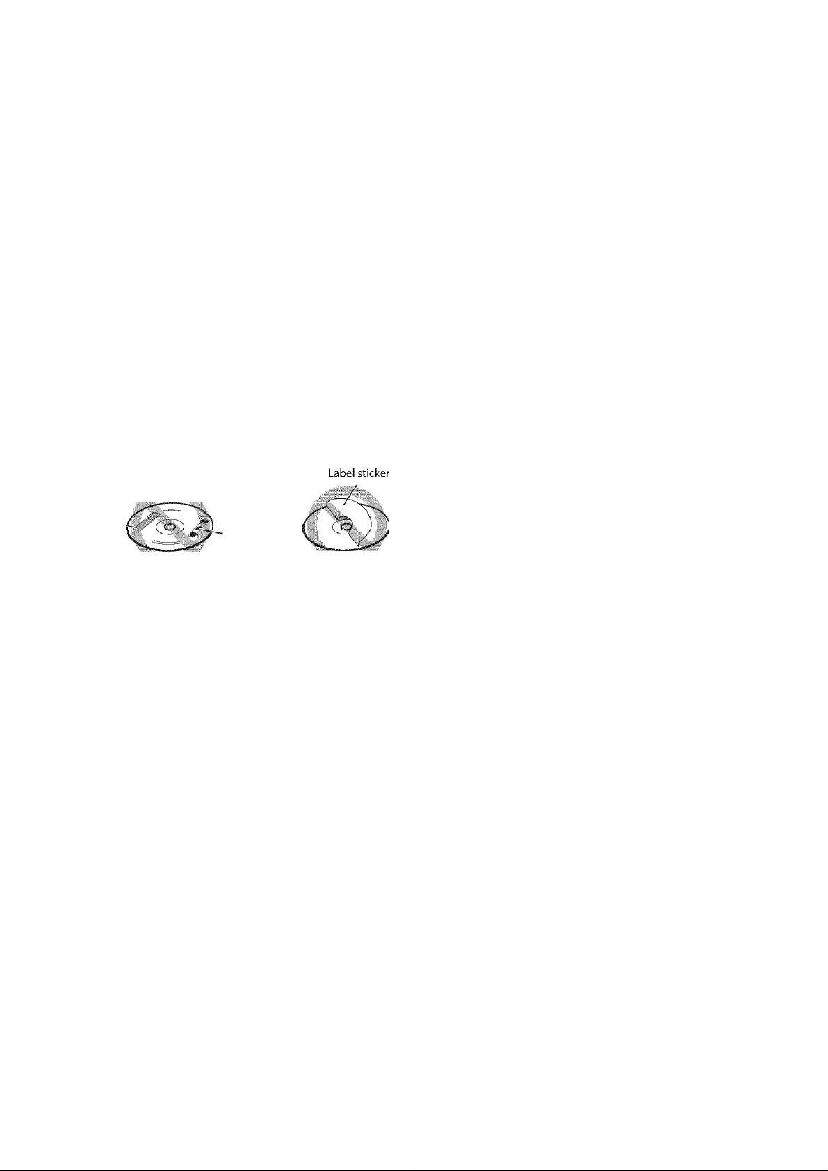
• Do not use any non-standard shape disc (like a heart, flower or
credit card, etc.) available on the market, because it may damage
the system.
• Do not use a disc with tape, stickers, or paste on it, because it may
damage the system.
■ Safety precautions
Avoid moisture, water and dust
Do not place the system in moist or dusty places.
Avoid high temperatures
Do not expose the system to direct sunlight and do not place it near
a heating device.
When you are away
When away on travel or for other reasons for an extended period of
time, disconnect the power cord plugs from the wall outlet.
Do not block the vents
Blocking the vents may damage the system.
Care of the cabinet
When cleaning the system, use a soft doth and follow the relevant
instructions on the use of chemically-coated cloths. Do not use
benzene, thinner or other organic solvents including disinfectants.
These may cause deformation or discoloring.
If water gets inside the system
Turn the system off and disconnect tlie power cord plug from the
wall outlet, then call the store where you made your purchase. Using
the system in this condition may cause a fire or electrical shock.
Supplied accessories
Sticker ■
Paste
Note about copyright laws
Check the copyright laws in your country before recording from the
discs. Recording of copyrighted material may infringe copyright
Note about copyguard system
The discs are protected by copyguard system. When you connect
the system to your VCR directly, the copyguard system activates and
the picture may not be played back correctly.
Check to be sure you have all of the supplied accessories.
The number in parentheses is tire quantity of the pieces supplied.
If anything is missing, contact your dealer immediately.
• Remote control (1)
• Batteries (2)
• FM antenna (1)
• AM loop antenna ( 1 )
• Power cord (1)
• System cord (1)
• Composite video cord ( 1 )
Page 6
About discs
Playable disc types
This syslom h;is Ix-a'i dcsi”rK\i lo pl.iy back ilia lollmvin” discs:
DVD VIDEO DVD AUDIO
UDIQ/VIDEO
VCD/SVC D
nCOMPACT
mm
iDIGITALVIDEOl
Video CD
f SUPER VI DEO i
wCD
The V in the list below shows available disc types and recording
formats.
Disc type
Recording
fornmt
DVD Video
DVD Audio
DVD VR
VCD/SVCD V
Audio CD V
MP3
WMA
JPEG
ASF
MPEG-2 k
MPEG-1 si
DivX
CD-R/-RW DVD-R DVD-RW
—
—
—
Audio CD
DIGITAL AUDIO
k k
■J k
■J k
—
—
>■2
>■2
>■2
t/*2
k*2
s/*2
t/*2 >■2
>■2
>.2
Notes on DVD-R and DVD-RW
• This system does not support “multi-border” disc.
Notes on CD-R and CD-RW
• This system can play CD-Rs or CD-RWs recorded with ISO 9660
format.
• This system supports “multi-session” discs (up to 20 sessions).
• This system cannot play “packet write” discs.
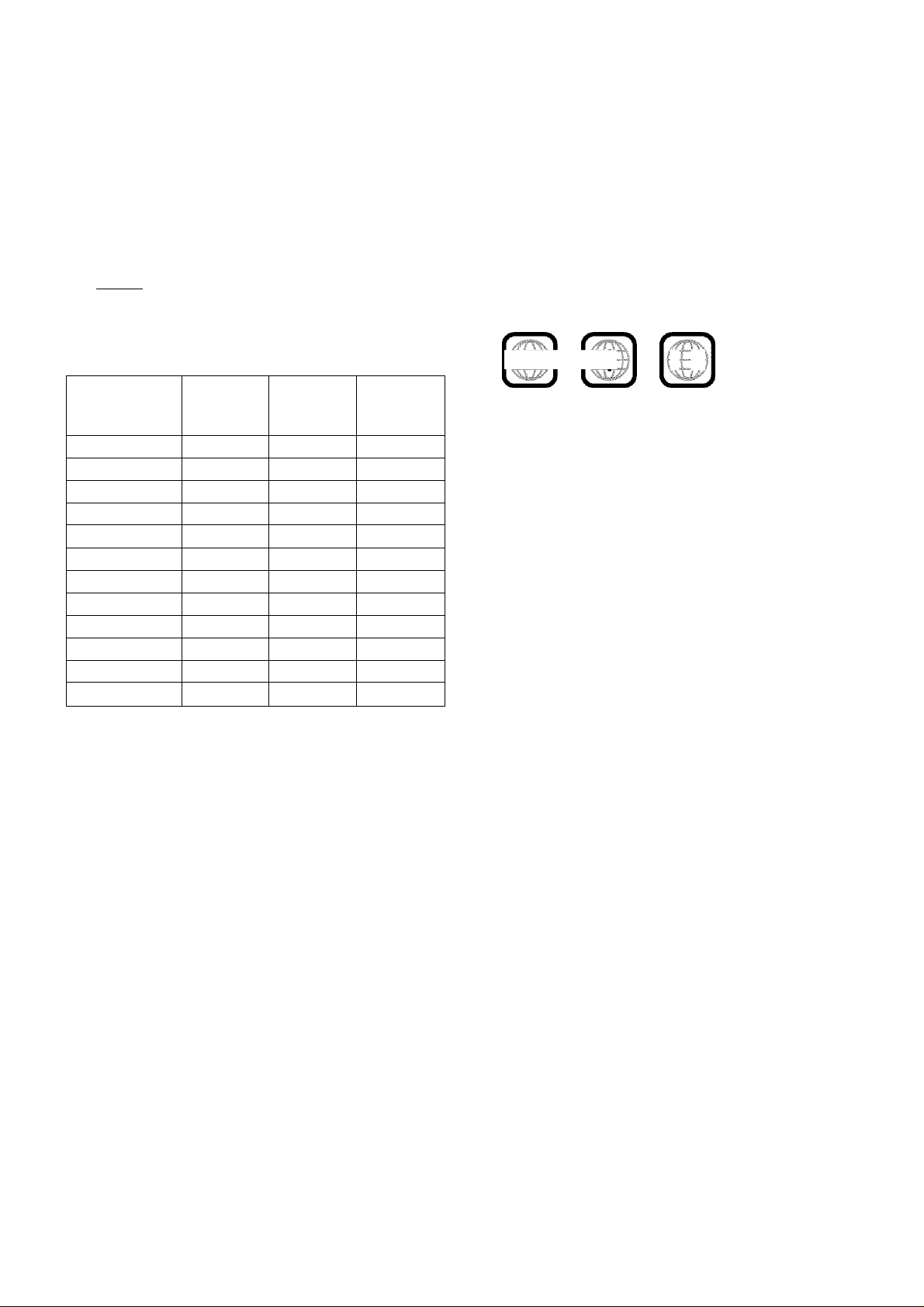
Region code of DVD VIDEO
DVD VIDEO players and DVD VIDEO discs have their own
Region Code numbers. This system can play back DVD VIDEO
discs whose Region Code numbers include the system's Region
Code, which is indicated on the rear panel.
Example of playable DVD:
1 2
lALil Ivli
12
3 4
If a DVD with an improper Region Code number is loaded,
“REGION CODE ERROR!” appears on the TV screen and playback
cannot start.
Some discs may not be played back because of their disc
characteristics, recording conditions, or damage or stain on them.
Unplayable discs
DVD-ROM, DVD-RAM, CD-I (CD-I Ready), Photo CD, SACD,
etc.
Playing back these discs will generate noise and damage the
speakers.
*' This system can play finalized discs only.
Recorded with UDF Bridge format.
• It is possible to play back finalized +R/+RW (DVD Video Format
only) discs. “DVD” lights on the display panel rvhen a +R/+RW
disc is loaded.
• This system accommodates the NTSC system, and also can play
discs recorded with PAL system. Note that an PAL video signal on
a disc is converted to the NTSC signal and output.
• The Non-DVD side of a “DualDisc” does not comply wdth the
“Compact Disc Digital Audio” standard. Therefore, the use of
Non-DVD side of a DualDisc on this product may not be
recommended.
. On some DVD VIDEOs, DVD AUDIOs, VCDs or SVCDs,
their actual operation maybe different from what is explained
in this manual. This is due to the disc programming and disc
structure, not a malfunction of this system.
DVD Logo is a trademark of DVD Format/Logo Licensing
Corporation.
Page 7

About discs
Playable file types
For all playable files
• The system can only recognize and play files with one of the
following extensions, which can be in any combination of upper
and lower case;
MP3: “.MP3” “.mp3”
WMA: “.WMA”, “.wma”
JPEG: “.JPG”, “.JPEG”, “.jpg”, “.jpeg”
ASF: “.ASF”, “.asf”
MPEG-2 /MPEG-1: “.MPG”, “MPEG”, “.mpg”, “.mpeg”
DivX: “.DIVX”, “.DIV”, ".diwc”, “.div”, and ".AVI”, ".avi”
• The system recognizes up to 150 tracks (files) per group, 99
groups per disc/device, and the total number of the tracks (files)
that the system can play is 4000.
• Some files may not be played back normally because of their disc
characteristics or recording conditions.
. MP3/WMA/JPEG/ASF/MPEG-2/MPEG- 1/DivX files require a
longer readout time. (It differs due to the complexity of the
directory/file configuration.)
• If different kinds of files are mixed, set the FILE TYPE setting in
the PICTURE menu to the appropriate setting for the data to be
read (“AUDIO”, "STILL PICTURE” or “VIDEO”). (See page 34.)
For MP3/WMA files
• The system supports MP3/WMA files recorded with a bit rate of
32 - 320 kbps and a sampling frequency of 16 kHz, 22.05 kHz, 24
kHz*, 32 kHz, 44.1 kHz, or 48 kHz.
• If the tag information (album name, artist, and track title, etc.) is
recorded, it appears in the file control display on the TV screen.
(See page 26.)
• We recommend to record each piece of material (song) at a
sample rate of 44.1 kHz and at a data transfer rate of 128 (96*)
kbps.
* For WMA only
For JPEG files
• We recommend to record a file at 640 x 480 resolution. (If a file
has been recorded at a resolution of more than 640 x 480, it will
take a longer time to be displayed.)
• This system can only play baseline JPEG files.
For ASF files
• The system supports the types of the advanced simple profile as
MPEG-4 files (MPEG-4 ASF).
• The system supports MPEG-4 files with the following conditions:
File format: ASF
Visual profile; MPEG-4 SP (Simple Profile)
Audio CODEC: G.726
Max. picture size; 352 x 288 (CIF)
Max. bit rate: 384 kbps
For MPEG-2/MPEG-1 files
• The stream format should conform to MPEG system/program
stream.
• 720 X 576 pixels (25 fps)/720 x 480 pixels (30 fps) is
recommended for the highest resolution.
• This system also supports the resolutions of 352 x 576/480 x 576/
352 X 288 pixels (25 fps) and 352 x 480/480 x 480/352 x 240 pixels
(30 fps).
• The file format should be MP(®ML (Main Profile at Main Level)/
SP@ML (Simple Profile at Main Level)/MP@LL (Main Profile at
Low Level).
• Audio streams should conform to MPEGl Audio Layer-2 or
MPEG2 Audio Layer-2.
For DivX files
• The system supports DivX 6.x, 5.x, 4.x and 3.11.
• The system supports DivX files whose resolution is 720 x 480
pixels or less (30 fps), and 720 x 576 pixels or less (25 fps).
• Audio stream should conform to Dolby Digital (including multi
channel) or MPEGl Audio Eayer-3 (MP3).
• The system does not support GMC (Global Motion
Compression).
• The file encoded in the interlaced scanning mode may not be
played back correctly.
• The system has its own Registration Code for DivX playback.
• If necessary, you can confirm the Registration Code of your
system using the OTHERS menu. (See page 35.)
This product incorporates copyright protection technology that
is protected by U.S. patents and other intellectual property rights.
Use of this copyright protection technology must be authorized
by Macrovision, and is intended for home and other limited
viewing uses only unless otherwise authorized by Macrovision.
Reverse engineering or disassembly is prohibited.
USE OF THIS PRODUCT IN ANY MANNER THAT
COMPLIES WITH THE MPEG-4 VISUAL STANDARD IS
PROHIBITED, EXCEPT FOR USE BY A CONSUMER
ENGAGING IN PERSONAL AND NON-COMMERCIAL
ACTIVITIES.
DivX, DivX Ultra Certified, and associated logos are trademarks
of DivX, Inc. and are used under license.
Official DivX* Ultra Certified product
Plays all versions of DivX® video (including DivX® 6) with
enhanced playback of DivX® media files and the DivX® Media
Format
Page 8
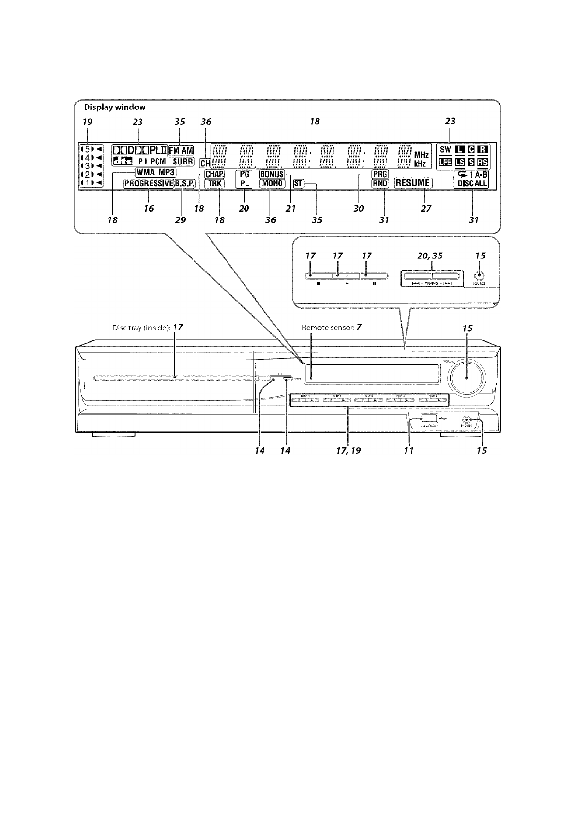
Description of parts and controls
Front panel (center unit)
The numbers in the figures indicate the pages where the details of the parts are described.
Page 9
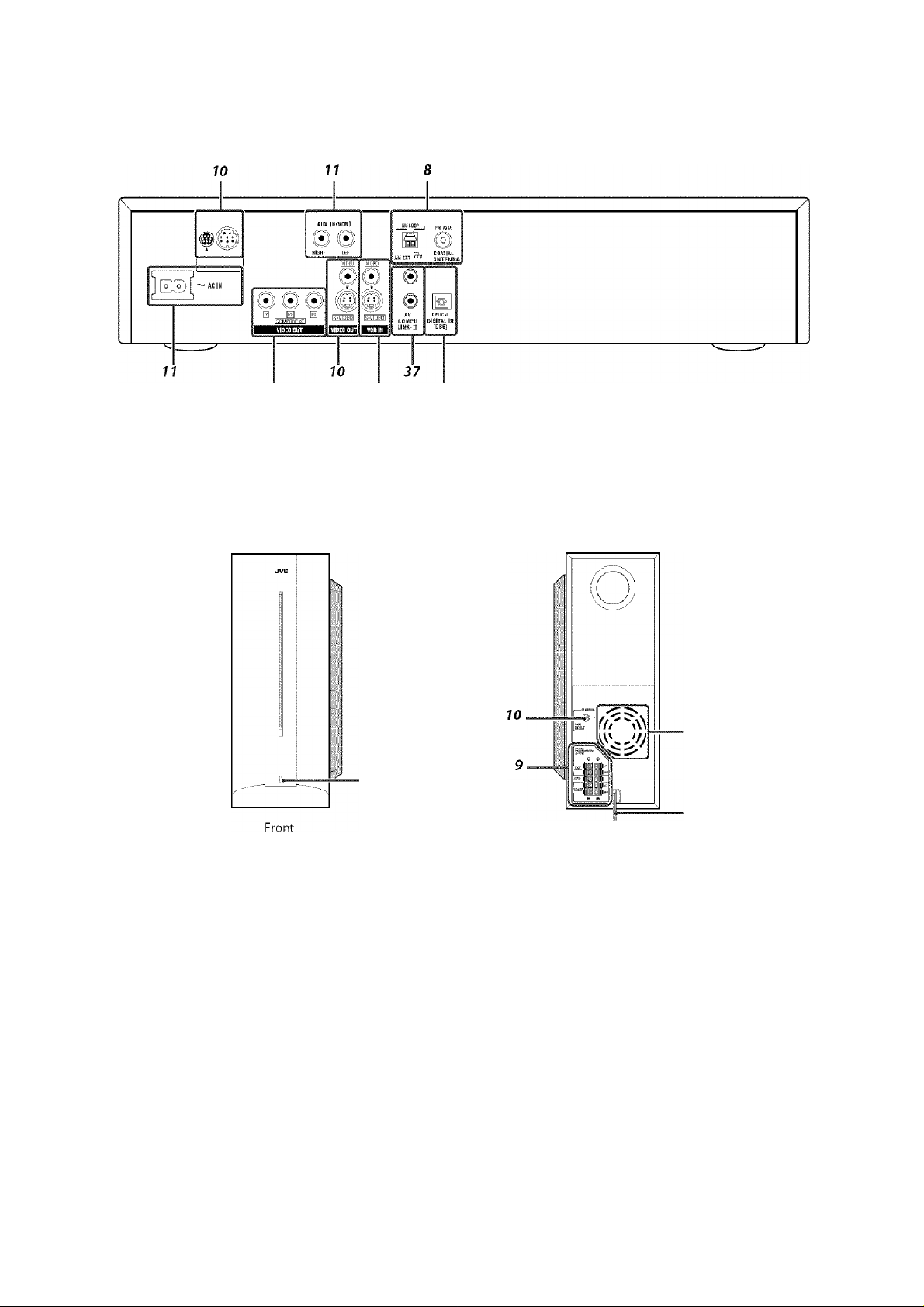
Description of parts and controls
Rear panel (center unit)
10 11 11
Powered subwoofer
SP-PWC30/SP-PWC20
Note that the illustration below is for SP-PWC30,
POWER ON
lamp: 14
NOTE
For safety reasons, always ensure that there is sufficient space behind
the powered subwoofer.
Rear
Power cord; 11
Do not block the ventilation openings to allow proper air
circulation by the cooling fan.
Page 10
Description of parts and controls
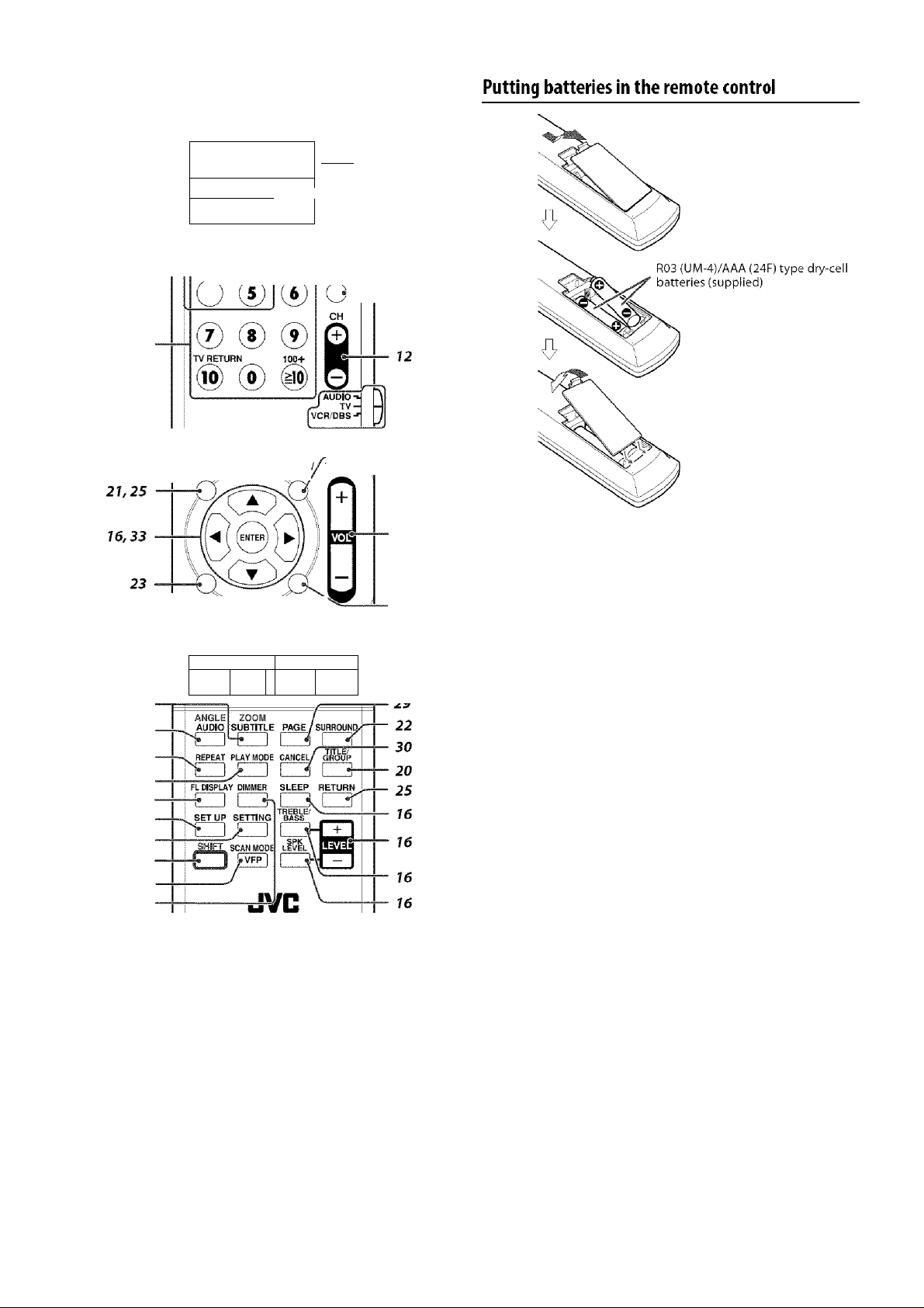
Remote control
15
Number
buttons: 20
'
1 1 1 1 1 1
1 1
DISC 1 DISC 2 DISC 3
USB
DVD
MEMORY FM/AM
VCR DBS
1
_____
AUDIO
i on 4-
VCR/DBS
1
1) @ ®
DISC 4 DISC 5
4) (1
/ TOP MENU/ MENU TV VOL
li^ONSCflEEN
\ REC MEMORY
' OTUNINGO O SLOW O
►H •44 ►►
PL ,
MUTING
FM MODE
TV
(Si
II
14
12, 13
12-35
21,25
12, 15
If the range or effectiveness of the remote control decreases, replace
both batteries.
CAUTION
• Do not expose batteries to heat or flame.
Operating the system from the remote control
Aim the remote control directly to the front panel of the center unit.
• Do not block the remote sensor.
Page 11
Connections
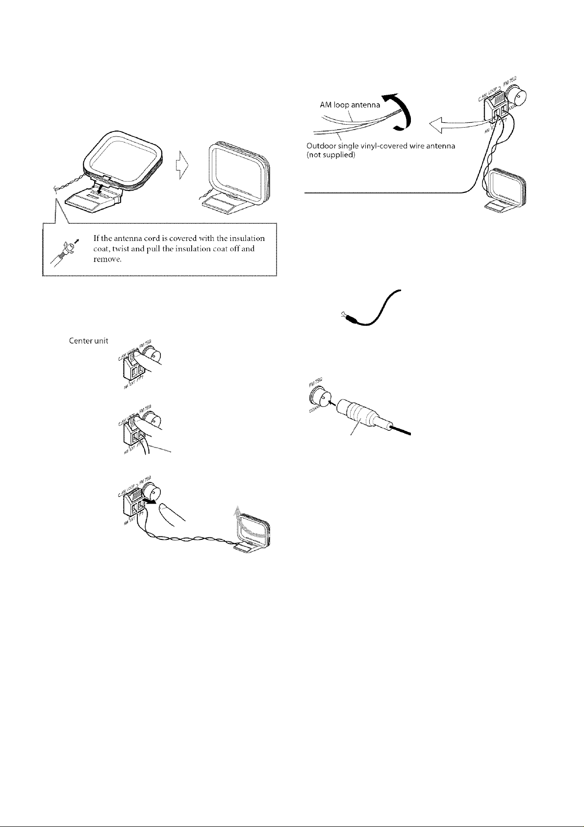
Connecting the FfVI and AfVl antennas
■ AM loop antenna
Setting up supplied AM loop antenna
Do not connect the power cord until all other connections have been made.
If reception is poor
Center unit
■ FM antenna
Connecting AM loop antenna
Antenna cord
Center unit
fttj;
If reception is poor
Center unit
Standard type (75 O
coaxial) connector
NOTE
We recommend that you use coaxial cable for the FM antenna as it is
well-shielded against interference.
FM antenna (supplied)
Extend the supplied FM antenna
horizontallv.
Outdoor FM antenna (not
supplied)
Outdoor FM antenna cord (not
supplied)
• Turn the loop antenna until you have the best reception during
AM broadcast program reception.
•
NOTE
• Make sure the antenna conductors do not touch any other terminals,
connecting cords or power cords. This could cause poor reception.
8
Page 12
Connections
Do not connect the power cord until all other connections have been made.
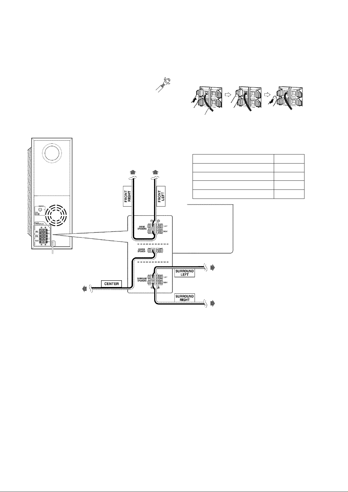
Connecting the satellite (front, center and surround) speakers to the subwoofer
Note that the illustration below is for SP-PWCSO.
Before connecting the speaker cords;
Twist and pull the insulation coat off and remove.
© ® © @ © ©
Powered subwoofer
TH-C30:SP-PWC30
TH-C20: SP-PWC20
Center speaker
TH-C30: SP-THC40C
TH-C20: SP-THC20C
Front speakers
TH-C30: SP-THC40F
TH-C20: SP-THC20F
Speaker cord
Connect the black cords to the black (©) terminals.
Connect the white cords to the (®) terminals
referring to the table below:
FRONT SPEAKERS (LEFT) White
FRONT SPEAKERS (RIGHT) Red
CENTER SPEAKER Green
SURROUND SPEAKERS (LEFT) Blue
SURROUND SPEAKERS (RIGHT) Gray
Surround speakers
TH-C30: SP-THC40S
TH-C20: SP-THC20S
CAUTION
If you connect speakers other than the supplied ones, use speakers of
the same speaker impedance (SPEAKER IMPEDANCE) indicated
near the speaker terminals on the rear of the powered subwoofer.
DO NOT connect more than one speaker to one speaker terminal.
When installing the satellite speakers on the wall;
- Be sure to have them installed on the wall by qualified personnel.
DO NOT install the satellite speakers on the wall by yourself to
avoid unexpected damage from falling off the wall due to incorrect
installation or weakness in wall structure.
- Care must be taken in selecting a location for speaker installation
on a wall. Injury to personnel or damage to equipment may result
if the speakers installed interfere with daily activities.
Precautions for daily use
• When moving the speakers, do not pull the speaker cords;
otherwise, the speakers may fall over, causing damage or injury.
• Do not reproduce sounds at so high a volume that the sound is
distorted; otherwise, the speakers may be damaged by internal
heat buildup.
Page 13
Connections
Do not connect the power cord until all other connections have been made.
Speaker layout
To obtain the best possible sound from this system, you need to
place all the speakers except the subwoofer at the same distance
from the listening position.
Center spet-iker
Front left
speaker
Front right
speaker
Powered
subwoofer
o
Surround left
speaker
If your speakers cannot be placed at the same distance from the
listening position
You can adjust the delay time of the speakers. See “Delay menu
(DELAY)” on page 34.
NOTE
Place the satellite speakers on a flat and level surface.
The front and center speakers are magnetically shielded to avoid color
distortions on TV s. However, if not installed properly, they may cause
color distortions. So, pay attention to the following when installing
the speakers.
- When placing the speakers near a TV set, turn off the TV’s main
power switch or unplug it before installing the speakers. Then wait
at least 30 minutes before turning on the TV’s main power switch
again.
Some TVs may still be affected even though you have followed the
above. It this happens, move the speakers away from the TV.
The surround speakers are not magnetically shielded.
If they are located nearby the TV or monitor, it will probably cause
color distortion on the screen. To avoid this, do not place the speakers
nearby the TV or monitor.
Be sure to place the powered subwoofer to the TV’s right. Ifyou place
the powered subwoofer to the TV’s left, keep sufficient distance
betcveen them to prevent the TV screen from appearing mottled.
Surround right
speaker
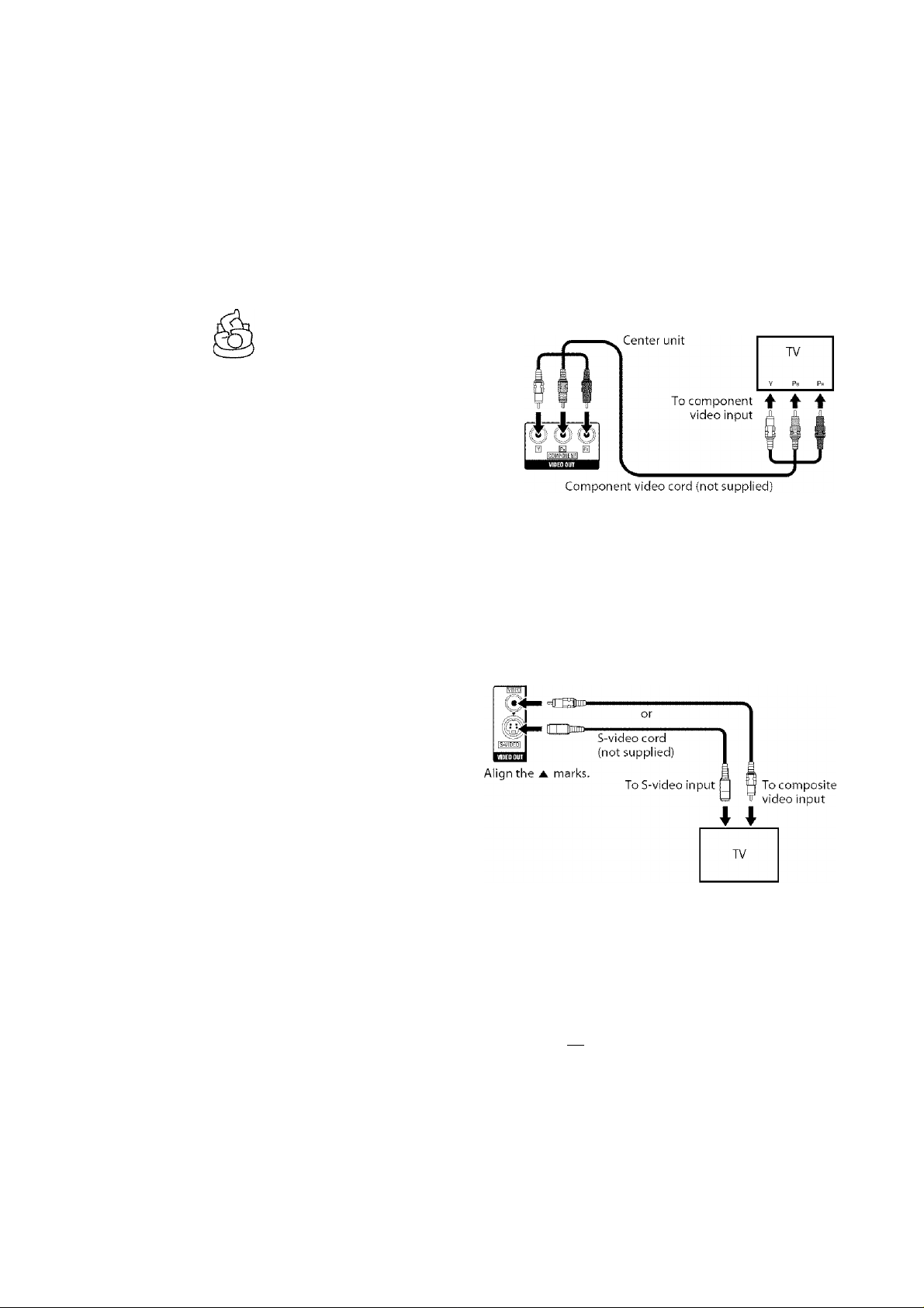
Connecting a TV
You can get better picture quality in the order — Component
video > S-video > Composite video.
Distortion of picture may occur when connecting to the TV via a
VCR, or to a TV with a built-in VCR.
You need to set “MONITOR TYPE” in the PICTURE menu
correctly according to the aspect ratio of your TV. (See page 34.)
I To connect a TV equipped with the component video input
jacks
If your TV supports progressive video input, you can enjoy a high
quality picture by setting the progressive scan mode to active,
(Seepage 16.)
NOTE
• If the component video input jacks of your TV are of the BNC type,
use a plug adapter (not supplied) to convert the pin plugs to BNC
plugs.
• The component video signals can be output only when you select
DVD or USB MEMORY as the source to play. (See page 15.)
■ To connect a TV equipped with the composite or S-video jacks
Center unit
Composite video cord (supplied)
Connecting the powered
subwoofer
Center unit
Align the
m n~Hnm>-
marks.
System cord
(supplied)
Powered
subwoofer
COhINECTOR
Align the A marks.
10
Page 14
Connections
Do not connect the power cord until all other connections have been made.
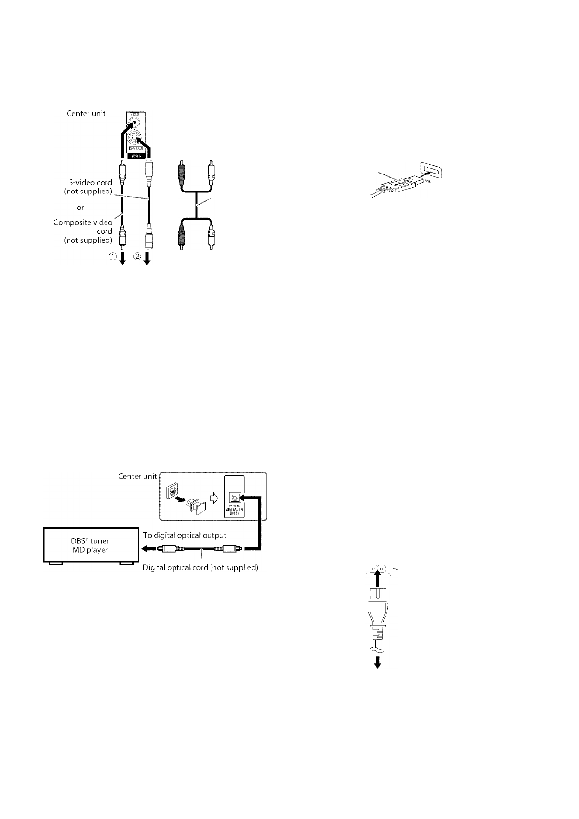
Connecting to an analog component
You can enjoy the sound of an analog component.
RCA pin plug
cord
(not supplied)
CD
VCR( ©C Do r@( D)
TV (CD)
Cassette recorder (@)
® To composite video output
(D To Swideo output
(D
To audio output
NOTE
The signals input to the VIDEO jack of the VCR IN jacks will be
output only from the VIDEO lack ofthe VIDEO OUT jacks, not from
the S-VIDEO jack ofthe VIDEO OUT jacks.
Connecting to a digital component
You can enjoy the sound of a digital component.
*
Connecting a USB mass storage class device
You can connect a USB mass storage class device such as a USB
flash memory device, hard disc drive, multimedia card reader,
digitili camera, etc. to this system.
• After connecting a USB mass storage class device to this system
and selecting “USB MEMORY” as the source, the control screen
appears on the TV screen. (See page 26.)
USB cable (not supplied) Center unit (on the
front panel
NOTE
When connecting a USB mass storage class device, refer also to its
manual.
Connect one USB mass storage class device to the system at a time. Do
not use a USB huh.
You cannot charge the USB mass storage class tlevice while
connecting it to the USB MEMORY jack.
While playing back a file in a USB mass storage class device, do not
disconnect the device. It may cause a malfunction of both the system
and the device.
JVC bears no responsibility for any loss of data in the USB mass
storage class device while using this system.
When connecting with a USB cable, use a cable less than 1 m in
length.
This system is compatible with the USB 2.0 Full-Speed (not
compatible with the USB 1.1).
You can playback the following types ot files in a USB mass storage
class tlevice (maximum data transfer rate: 2Mbps):
- Music: MP3. WMA
- Picture: JPEG
- Movie: MPEG-4 (ASF), DivX (maximum frame rate of 30 fps for
progressive)
You cannot playback a file larger than 2GB.
When playing a tile which has a large transfer rate, frames or sounds
may be dropped during playback.
This system cannot recognize a USB mass storage class device whose
rating exceeds 5V/500 mA.
This system may not recognize some USB mass storage class devices.
This system may not playback some files even though their formats
are listed above.
* DBS = Direct Broadcasting Satellite
NOTE______________
• Only digital audio signals can be input when selecting “DBS” as the
source to play. (See page 15.) When connecting a video component
such as a DBS tuner, operate this system to listen to the sound.
n
Connecting the power cord
Make sure that all other connections have been completed.
Center unit y
Power cord
CAUTION
Disconnect the power cord before cleaning or moving the system.
Do not pull on the power cord to unplug the cord. When unplugging
the cord, always grasp and pull the plug so as not to damage the cord.
(Supplied)
..........
'p Powered
Plug Into AC outlets.
subwoofer
Power cord
Page 15

Operating external components with the remote control
Press number buttons (1-9,0) to enter
the manufacturer's code (2 digits).
Examples:
For a Hitachi TV: Press 1, then 0.
For a Toshiba TV: Press 0, then 8.
Manufacturer Code Manufacturer Code
JVC 01» Samsung 12
Hitachi to Sanyo 13, 14
Magnavox 02 sharp 06
Mitsubishi 03
Pcinasonic 04, 11 Toshiba 08
Philips 15 Zenith
RCA 05
* “01” is the initial setting.
5 Release 0/1 TV.
If there is more than one code listed for corresponding brand,
try each one until you enter the correct one.
■ Operation
Aim the remote control at the TV.
IMPORTANT
Before using the remote control to operate a TV;
. Set the remote control mode selector to TV.
Sony
07
09
NOTE
Manufacturers’ codes are subject to change without notice.
Set the codes agiiin after replacing the batteries of the remote control.
Operating the TV
■ To set the manufacturer's code
1 Slide the remote control mode selector
to TV.
2 Press and hold C!)/l TV.
Keep the button pressed until step 4 is finished.
3 Press ENTER.
The following buttons are available:
0/1 TV: Turns TV on and off.
TV VOL +/-: Adjusts the volume.
TV/VIDEO: Selects the input mode (either TV or
VIDEO).
CH +/-; Changes the channels.
1 -10, 0, Si0 (100+): Selects the channel.
TV RETURN: Alternates between the previously selected
channel and the current channel.
NOTE
. The operating buttons may differ depending on manufacturers.
Operating the DBS tuner or CATV converter
■ To set the manufacturer's code
1 Slide the remote control mode selector
to VCR/DBS.
2 Press DBS.
3 Press and hold 0/1 VCR/DBS.
Keep the button pressed until step ;> is finished.
4 Press ENTER.
Continued on the next page
12
Page 16

Operating external components with the remote control
See page 12 for button locations.
Press number buttons (1-9,0) to enter
the manufacturer's code (2 digits).
Examples:
For a GI Jerrold product:
Press 0, then 1.
For a Sony product:
Press 2, then 0.
Manufacturer Code
EchoStar 21
GI Jerrold 01*, 02. 03,04. 05.06,07,08
Hamlin IS, 16,17, 18
Pioneer
RCA
Scientific Atlanta
Sony 20
Zenith 11. 12
* “01” is the initial setting.
13, 14
19
09. 10
6 Release Ci)/I VCR/DBS.
If there is more than one code listed for your brand, try each
one until you enter the correct one.
■ Operation
Aim the remote control at the DBS tuner or CATV converter.
IMPORTANT
Before using the remote control to operate a
DBS tuner or CATV converter;
1 Set the remote control mode selector
to VCR/DBS,
2 Press DBS.
The following buttons are available:
0/1 VCR/DBS: Turns DBS tuner or CATV converter on and
off
CH +/-: Changes the channels,
1-10, 0, SIO (1 00-1): Selects the channel.
VCR/DBS-'
J DBS
Operating the VCR
■ To setthe manufacturer's code
1 Slide the remote control mode selector
to VCR/DBS.
2 Press VCR.
3 Press and hold 0/1 VCR/DBS.
Keep the button pressed until step ,5 is finished.
4 Press ENTER.
Press number buttons (1-9,0) to enter
the manufacturer's code (2 digits).
Examples:
For a Philips VCR:
Press 0, then 9.
For an NEC VCR:
Press 2, then 5.
Manufacturer Code Manufacturer Code
JVC 01*. 02, 03 Philips
Emerson 11,26 RCA 05. 06
Fisher 29 Samsung 24
Funai 10, 14, 15, 16 Sanyo 21,22,23
Gold Star 12 sharp 27. 28
Hitachi 04 Shintom 30
Mitsubishi 13
NEC 25 Zenith 08
Piuiasonic 07, 17
* “01” is the initial setting.
Sony
09
18. 19. 20
6 Release 0/1 VCR/DBS.
If there is more than one code listed for your brand, try each
one until you enter the correct one.
■ Operation
Aim the remote control at the VCR.
IMPORTANT
Before using the remote control to operate a
VCR;
1 Set the remote control mode selector
to VCR/DBS.
2 Press VCR.
The following buttons are available:
0/1 VCR/DBS: Turns VCR on and off.
► (play button): Starts playback.
■ : Stops operation.
II: Pauses playback.
►►: Fast forwards video tape.
: Rewinds video tape.
REC: Press this button together with ► (play
button) to start recording or together with II
to pause recording.
CH +/-: Changes the TV channels on the VCR.
NOTE
When operating a VCR or DBS tuner/CATV converter;
The source setting of VCR or DBS remains after you have changed the
remote control mode selector to AUDIO or TV. When operating VCR
or DBS tuner/CATV converter again, it is not necessary to press VCR
or DBS after setting the remote control mode selector.
VCR/DBS-^
i 1 VCR
j V I :-: . 2j
13
Page 17

Basic operations
The buttons on the remote control are used to explain most of the
operations in this manual. You can use the buttons on the center
unit same as on the remote control for operations unless
otherwise noted.
IMPORTANT
Turning the system on/off
On the remote control:
Press 0/1 AUDIO.
On the center unit:
Press C!)/l.
When DVD or USB MEMORY is selected as the source (see page
i 5), the following messages will appear on the TV screen.
illiiji
r
“OPEN’TCLOSE”:
Appears when opening or closing the disc tray.
“NOW READING”
Appears when the system is reading the disc/file information.
“REGION CODE ERROR!”:
Appears when the Region Code of the DVD VIDEO does not
match the code the system supports. The disc cannot be
played back.
“NO DISC”:
Appears when no disc is loaded.
“NO USB DEVICE”:
Appears when no USB mass storage class device is connected.
“CANNOT PLAY THIS DISC”:
Appears when unplayable disc is loaded.
“CANNOT PLAY THIS DEVICE”:
Appears when unplayable USB mass storage class device is
connected.
NOTE
The STANDBY lamp turns on when the power is turned off and turns
off when the power is turned on.
The power supply to the subwoofer is linked to the center unit. The
POWER ON lamp on the subwoofer lights green when the power is
turned on.
A small amount of power is consumed even when the power is turned
off (center unit only). This is called standby mode and the STANDBY
lamp lights in this mode. Unplug the power cord from the AC outlet
to turn the power ott completely.
You can also turn on the system by pressing the following buttons:
- One of the DISC (T5) buttons (with SHIFT pressed) on the remote
control
- One of DISC (1-5) ^ buttons on the center unit
- One of the source selecting buttons or ► on the remote control
- One of the DISC (1-5) ► buttons or ► on the center unit.
14
Page 18

Basic operations
See page 14 for button locations.
Selecting the source to play
On the remote control:
Press one of the source selecting buttons (DVD, USB MEMORY, FM/AM, VCR or DBS).
DVD:
To play back a disc (DVD VIDEO, VCD etc.). (See page 17.)
USB MEMORY:
To playback a file in a USB mass storage class device. (See page “To
play a file in a USB mass storage class device” on page 17.
FM/AM:
To tune in an FM or AM station. (See page 3.5.) Each time you press
the button, the band alternates between FM and AM.
VCR:
To select the source from a component connected to the VCR IN
jacks and AUX IN (VCR) jacks. (See page 11.)
DBS:
To select the source from a component connected to the DIGITAL
IN (DBS) jack. (See page 11.)
On the center unit:
Press SOURCE repeatedly until the source
name you want appears on the display
window.
NOTE
When AM, FM or DBS is selected, this system does not output video
signals.
It miiy take time to chimge the source.
Adjusting the volume
[VOLUME]
CAUTION
« Always set the volume to minimum level before starting any source.
If the volume is set at a high level, the sudden blast of sound coukl
permanently damage your hearing and/or blow out the speakers.
On the remote control:
Press VOL +/-.
On the center unit:
Turn VOLUME.
. To increase the volume, turn VOLUME clockwise.
• To decrease the volume, turn VOLUME counterclockwise.
Listening with headphones (not supplied)
CAUTION
Be sure to turn down the volume;
• Before connecting or putting on headphones as high volume may
damage both the headphones and your hearing.
• Before disconnecting headphones as high volume may be suddenly
output from the speakers.
While connecting a pair of headphones to the PHONES jack on the
center unit, the system automatically cancels the surround mode
(see page 22) currently selected, deactivates the speakers, turns the
subwoofer’s power off, and activates the headphone mode.
“H. PHONE” appears on the display window.
Headphone mode
When using the headphones, the following signals are output
regardless of your speaker setting;
• For 2 channel sources, the front left and right channel signals are
output from the headphones.
• Multi-channel signals are down-mixed and output from the
headphones.
• (For DV.D AUDIO) When the disc prohibits down-mixing, only
the front left and right channels are output from the headphones.
Turning off the sound temporarily [MUTING]
Press MUTING.
To restore the sound
Perform one of the following:
• Press MUTING again.
• Press VOL t-/- (or turn VOLUME on the center unit).
Adjusting the brightness of the
indications [DIMMER]
Press DIMMER.
Each time you press the button, you can change the brightness level
in 3 steps.
15
Page 19

Basic operations
See page 14 for button locations.
Sleep Timer [SLEEP]
The system turns off automatically when the specified period of
time has passed.
Press SLEEP.
Each time you press the button, the shut-off time changes.
Example:
minutes
SLEEP 60
To check the remaining time
Press SLEEP once.
To change the remaining time
Press SLEEP repeatedly.
To cancel
Press SLEEP repeatedly until “SLEEP —” appears.
• Turning off the power also cancels the Sleep Timer.
Adjusting the output level of the subwoofer and speakers
1 Press SPK LEVEL to show the target
speaker indication on the display
window.
Each time you press the button, the indication of the speakers
changes as follows:
FRNT L (Front Left speaker) ^ FRNT R (Front Right
speaker) ^ CENTER (Center speaker) ^ SURR L
(Surround Left speaker) ^ SURR R (Surround Right
speaker) ^ SUBWFR (Subwoofer) ^ (back to the
beginning)
Press LEVEL +/- to adjust the output
level from -6 to +6.
NOTE
You can also make adjustments by using the setup menu shown on
the TV screen. (See page 34.)
The adjustments take effect for all sources.
Changing the scan mode
The system can be accommodated to your TVs scan mode.
NOTE______________
• To use the system in the progressive mode, it is required that the
center unit is connected to the TV by using a component video cord
(not supplied). (See page 10.)
■ While DVD or USB MEMORY is selected as the source and
stopped
7 Press and hold SCAN MODE for
2 seconds.
Currently selected scm mode appears on the display window,
2 Press Cursor ► / ◄ to select the desired
mode.
Each time you press the button, the scan mode changes as
follows:
• 480i*: Select this to change the scan mode to interlace mode.
. 480p*: Select this to change the scan mode to progressive
mode.
* 480i and 480p indicate the number of scanning lines and
scanning format of a video signal.
-4801 indicates 480 scanning lines with interlaced format.
-480p indicates 480 scanning lines with progressive format.
. You can get better picture quality in the progressive mode
than in the interlace mode.
3 Press ENTER while the selected mode is
displayed.
When the progressive mode is selected, the PROGRESSIVE
indicator lights on the display window.
NOTE
Although the picture mc\y be distorted when you press ENTER, this is
not a malfunction of the system.
There are some progressive TVs and High-Definition TV^s that are
not fully compcitible with this system, resulting in an unncitural
picture when playing back a DVD VIDEO in the progressive scan
mode. In such a case, change the scan mode to the interlace mode.
To check the compatibility of your TV, contact your local JVC
customer service center.
All JVC progressive TVs and High-Definition TVs are fully
compatible with this system.
Adjusting the sound
7 Press TREBLE/BASS to show "TRE" or
"BASS" on the display window.
Each time you press the button, the indication alternates
between “TRE” and “BASS”.
• TRE: Select this to adjust treble sound,
. BASS: Select this to adjust bass sound.
2 Press LEVEL +/- to adjust the level from
- 10 to +10 (in 2 steps).
NOTE
The adjustments take effect for all sources.
16
Page 20

Playback
• The icon such as shows tlie disc formats or file types the
operation is available for.
IMPORTANT
Before using the remote control for the
following operation;
1 Set the remote control mode selector
to AUDIO.
2 Press DVD or USB MEMORY.
^
AUDIO -L
DVD
..........................
1 . *
Basic playback
i
Press the desired DISC (1-5)
To play a disc
^ on the center unit.
• The system turns on and the disc tray comes
out.
IBS!
1W3
IgUI
Place a disc.
Label side up When placing an 8 cm disc
DVD
VR
CD
ASF
3 Pi
NOTE
• Up to 5 discs can be loaded.
• You can also start playback by pressing ► (play button) or DVD.
• The system plays back available discs sequentially until you stop
playback or until the disc loaded on the DISC 5 tray reaches to the
end. However, when DVD VIDEO or DVD AUDIO is loaded in the
system, playback of the disc next to the DVD VIDEO or DVD
AUDIO will not start,
P
-----------------------------------------------------------------
1................................................................
^ u.
---------------------------------------------------------------
DISC 1-5
1 rV, ll
irCKS-lS ¿rctsa !TSiS2j)' j
■ To play a file in a USB mass storage class device
Press USB MEMORY.
The operations of the files in a USB mass storage class derhce
depend on the file types stored in the device.
For MP3/WMA files
The file control display (see page 26) appears on the TV screen.
For JPEG files
Each file (still pictures) is shown on the TV screen for about 3
seconds (slide-show). When stopping playback, the file control
display (see page 26) appears on the TV screen.
For ASF/MPEG-2/MPEG-1 files
Pressing TOP MENU/PG or MENU/PL shows the file control display
(see page 26) on the TV screen during playback.
For DivX files
During the readout time, “READING INDEX” may appear on the
TV screen.
Pressing TOP MENU/PG or MENU/PL shows the file control display
(see page 26) on the TV screen during playback.
NOTE
. When several types of files are recorded on a disc/device, select
appropriate file type on the set up menu. (See page 34.)
■ To pause playback
Press II.
To continue playback, press ► (play button).
■ To Stop
Press ■.
NOTE______________
• (For JPEG) The system cannot accept operations even though you
press any buttons before the entire picture appears on the TV screen.
17
Page 21

Playback
See page 17 for button locations.
■ On-screen guide icons
During DVD VIDEO playback, the following guide icons may
appear for a while on the TV screen;
• appears at the beginning of a scene containing multi-subtitle
languages.
• appears at the beginning of a scene containing multi-audio
languages.
: appears at the beginning of a scene contiiining multi-angle
views.
. O(Plav), m (Pause), Ç I / (Fast forward/
fast-reverse), ■ | ft (Slow-motion forward/
reverse) appeals when you perform each operation.
• ® : the disc cannot accept an operation you have tried to do.
NOTE
• If you do not want the on-screen guide icons to apipear, see page 35.
■ Playback information on the display window
DVD VIDEO
Example: When a DVD VIDEO encoded with Dolby Digital S.lch
is played
Elapsed playing time
(hour:minute:second)
□□D
Chapter number
sJf2 4l 1:2 3:3llii®i
V
Signal and speaker indicators (See page 23.)
Surround mode and digital signal format (See page 23.)
VCD/SVCD/CD
Example: When a CD is played back
Elapsed playing time (hour:minute:second)
NOTE
• When a VCD or SVCD with PBC function is played, the elapsed
playing time does not appear, but “PBC” appears,
MP3/WMAfile
Example: When an MP3 file is played back
Track number
Signal and speaker
indicators
^fTT^IoTTTriTl
MP3 indicator* Elapsed playing time (hour:minute:second)
^ Pressing FL DISPLAY
Group number
(during playback only)
Pressing FL DISPLAY
DVD AUDIO
Pressing FL DISPLAY
Title number Chapter number
1
tTTI fTT4
Signal and speaker indicators
2 1
' 1
Track number Elapsed playing time
Group number Track number
[ 1: 2 3; 4 5
"^fsw D □ )
J
,
(hour:minute:second)
Track number
WMA indicator lights for WMA file.
JPEG file
File number
12 3 JPEG
Pressing FL DISPLAY
Group number File number
G 1 2 F 1 2 3 -- -
Continued on the next page
18
Page 22

Playback
See page 17 for button locations.
ASF/MPEG-2/MPEG-1 /DivX file
Example: When an ASF file is played.
Track number
( 1 2 aliO: 1 0;
TFIK
Elapsed playing time (hour:minute:second)
(during playback only)
Pressing FL DISPLAY
Group number
G i 2
V---------------------------
DVD VR disc
Example: During playback on the Original program*
Chapter number
Elapsed playing time
(hour:minute:second)
3—bwb Q
Track number
T 1 2
---------------------
Signal and speaker indicators
_____________1__________
—( 2 2 )
..............
Pressing FL DISPLAY
Example: During playback on the Playlist*
Chapter number
0: 2 0: 3 6 “
...........................................................................................I
Title number Chapter number
Elapsed playing time
(hour:minute:second)
■ Disc information on the dispiay window
The disc indicators on the display window show the current status
of the corresponding disc tray.
Example: When the discs are loaded to disc trays 1, 2 and 5, and the
disc in the disc tray ;> is selected.
Currently selected disc
number
Currently loaded disc number
■ Screensaver
An image may burn in on a TV screen if a static picture is displayed
for a long time. To prevent this, the system automatically dims the
screen if a static picture is displayed for over 5 minutes (the screen
saver function).
• Pressing any button "will ciuicei the screen saver function.
• If you do not want to use the screen saver function, see page 34,
One Touch Replay
You can move back the playback position by 10 seconds
from the current position,
■ During playback
On the remote control:
Press <T.
NOTE
• This function works in the same title.
• This function is not available during the repeat playback.
• This feature may not work for some discs.
H 3 0 fO: 5 Ò: 3 0
Pressing FL DISPLAY
Playlist number Chapter number
p.L
......
t||C 3 0
* Pressing TOP MENU/PG or MENU/PL, you can change the play
mode. (See page 21.)
NOTE
You can change the time information mode (except for MP3/WMA/
ASF/MPEG-2/AlPEG-l/DivX). (See page 24.)
You can also check the playback information on the TV screen. (See
page 23.)
sw n □
19
Page 23

Playback
Fast-forward/fast-reverse
search
■ During playback
On the remote control:
Press ►► or
Each time you press the button, the search
speed changes (x2, x5, xlO, x20, x60).
To return to normal speed playback
Press ► (play button).
On the center unit:
Press and hold or
Continuously pressing ►►! or increases the fast-forward/
reverse search speed (x.5, x20).
NOTE
The operation with or 1-^-^ above is available for a disc/file other
than MP3, WMA, ASF, MPEG-2. MPEG-1, and DivX.
When a DVD VIDEO, DVD VR, VCD, SVCD, or ASF/MPEG-2/
MPEG-l/DivX is played back, no sound comes out during fastforward/reverse search.
When a DVD AUDIO, CD, or MP3/WMA is played back, sound is
intermittent and low during fast-forward/reverse search.
This feature may not work for some discs/files.
For MP3/WXIA, the search speed is not shown.
The search speed for DivX is ►► 1, ►► 2, ►► 3 for forward search,
and 1, -^-<2 and for reverse search.
Skip to the beginning of a
desired selection
DVD
JPEG
DivX
VR
CD
ASF
■ Using buttons
■ For DVD VIDEO/DVD VR (chapter): During
playback
■ For VCD/SVCD (track): During playback
without PBC function
■ For DVD AUDIO/CD/iVlP3/WMA/JPEG/
ASF/MPEG-2/MPEG-l/Diri^X (track/file): During playback or
while stopped
Press or repeatedly.
NOTE
. When playing back an MP3/WiMA/JPEG/ASF/MPEG-2/MPEG-1 /
DivX tile, you can make operations using the file control display. (See
page 26.)
• This feature may not work for some discs/files.
■ Using number buttons on the remote controi
■ For DVD VIDEO/DVD VR (title, chapter):
While stopped, the title number is selected.
.During playback, the chapter number is selected.
■ For DVD AUDIO (track):
During playback or while stopped
■ For VCD/SVCD (track):
.During playback or while stopped without PBC function
■ For CD/MP3/WMA/JPEG/ASF/MPEG-2/MPEG-l/DivX
(track/file):
.During playback or while stopped
Press number buttons (0-10, ^10) to
select the desired number.
See page 17 for button locations.
For details on using the number buttons, see “How to use the
number buttons” below.
How to use the number buttons
To select 3: Press 3.
To select 10: Press 10.
To select 14: Press Si 0, 1, then 4.
To select 24: Press SlO, 2, then 4.
To select 40: Press SlO, 4, then 0.
To select 114: Press SI 0,S 10, 1, 1, then 4,
Skipping at about 5-minute intervals
You can skip within the file at about 5-minute intervals,
This is useful especially when you want to skip within a 111111
long file.
■ During playback
Press Cursor ►/◄.
Each time you press the button, the playback position skips to the
beginning of the previous or next interval. Each interval is about
5 minutes,
NOTE
Intervals are automatically assigned from the beginning of a file.
This feature is available only within the same file.
This feature may not work for some discs/files.
Locating a desired title/group using number buttons
■ During playback or while stopped
7 Press TITLE/GROUP.
“—” is shown in the title/group display area
in the display windowt
Example: During DVD VIDEO playback
T - 1: 2 3: 4 5
While the display window shows
use number buttons (0-10, ^10) to
enter the desired title or group
number.
The system starts playback from the first chap ter/track/file of
the selected title/group.
. For details on using the number buttons, see “How to use the
number buttons” above.
NOTE
When locating a title of a DVD VR disc, PG or PL indicator may light
on the display window.
This feature may not work tor some discs/files.
20
Page 24

Playback
See page 17 for button locations.
Playing back a bonus group
Some DVD AUDIOS have a special group called “bonus
group” whose contents are not open to the public. The
bonus group is always assigned to the last group of a disc. To
play back a bonus group, you have to enter the specific “key
number” (a password). The way of getting the key number depends
on the disc. After getting the key number, you can play back the
bonus group by following the procedure below.
While the BONUS indicator lights up on the display window
1
Select the bonus group.
For selecting the group, see “Locating a desired title/group
using number buttons” described above.
The key number entry indication appears.
On the TV
KEY -!
Oil the display window
KEY
BONUS
2 Press number buttons (0-9) to enter the
key number, then press ENTER.
When you enter the correct key number, playback starts and
the BONUS indicator goes off
. If you enter the wrong number, reenter the correct number.
To clear the key number entry
Perform whichever one of the following:
. Press ■.
. Open the disc tray.
. Turn off the system.
NOTE
In Random Playback, tracks in the bonus group are not played back.
Selecting the desired title/
playlist from the control
display
During playback or while stopped.
1
Press TOP MENU/PG or MENU/PL
The control display is shown on the TV screen, and the sy'stem
starts playback of the first title/playlist.
. The PLAY LIST is shown only when the playlist is on the
DVD VR disc.
TOP MENU/PG: shows the ORIGINAL PROGRAM.
Example:
.liPfeiyÁLWOQkAa:
No Date
2 17/05/04 8ch 10;30
3 22/05/04 8ch
4 26/05/04 L-1 13:19
5 20/06/04 4ch 22:00
, 6„25/06/04, ,L-1.
*1
*1
Title number
Recording date
*2
*3
Recording source (TV station, the input terminal of the
recording equipment etc.)
*4:
Start time of recording
*5:
Title of the original program/playlist (The title may not be
displayed depending on the recording equipment.)
Current title
*6:
MENU/PL: shows the PLAY LIST.
Example:
■.PL:f.ytlST-:
:\o Oato Chap Title
2 ;7.'05'G4 005 1:35:25
3 20/06/04
. 4,.25/06/04, |001 , .0:07:19, .childrenOOI-002
Ch
Time Title i
•19.Ü.Ü.'
■■■«cDWworidaooT]—j
17:00 Music Festival
children 001
.children 002 , :
, 8:23,
■r:83:46: Mv JVC Wcrid:
003 0:10:23 Favorite music
*6
1ÍH
27
*7 *8 *9 *10 *5 *11
Playlist number
Creating date of playlists
Number of chapters
*10: Total playing time
*11: Current playlist
2 Press Cursor ▼ / A to select the desired
title/playlist.
The system starts playback of the selected title/playlist.
To clear the control display
Press ENTER.
About the play mode on a DVD VR disc
. Original program (ORIGINAL PROGRAM):
The system can play back the original picture in the recorded
order.
. Playlist (PLAYLIST):
The system can play back the playlist edited by the recording
equipment.
Page 25

Advanced operations
• The icon such as shows tlie disc formats or file types the
operation is available for.
IMPORTANT
Before using the remote control for the following
operation;
• Set the remote control mode selector to AUDIO.
• There are exceptions in the operation mentioned
above. In such a case, follow each instruction.
The buttons described below are used on pages 22 to 32.
Remote
control mode
selector
MENU/PL
(play button)
II
• SLOWO/O
PAGE
SURROUND
CANCEL
Using the surround mode
You can enjoy more realistic sound field than a stereo sound by
using the surround mode.
■ Auto Surround (AUTO SUR)
Used to reproduce the sound as it is recorded without any
conversion (downmixing or simulation, etc.). For example, a
multichannel source is automatically reproduced in multichannel
audio.
■ Dolby Surround
Dolby Pro Logic M*'
Dolby Pro Logic II has a newly developed multichannel playback
format to decode all 2 channel sources — stereo source and Dolby
Surround encoded source — into a ;S.l channel.
Dolby Pro Logic II has two modes — Movie mode and Music mode:
. Pro Logic II Movie (MOVIE)
Suitable for reproduction of Dolby Surround encoded sources
bearing the mark □□Iqqi.byslwroumdi .
. Pro Logic II Music (MUSIC)
Suitable for reproduction of any 2 channel stereo music sources.
Dolby Digital^^
Used to reproduce multichannel soundtracks of the software
encoded with Dolby Digital
• There are other encoding formats of digital surround introduced
by Dolby Laboratories, such as Dolby Digital EX.
■ DTS Digital Surround^^
Used to reproduce multichannel soundtracks of the software
encoded with DTS Digital Surround (^3 )•
DTS Digital Surround (DTS) is another discrete multichannel
digititi audio format available on CD and DVD softw’are.
• There are other encoding formats of multi-channel digitili
surround introduced by Digital Theater Systems, Inc., such as
DTS-ES, DTS 96/24. '
RETURN
VFP
Available Surround modes for each input signal
The V marks show available surround modes.
Mode Surround
Signal OFF AUTO SUR MOVIE*^ MUSIC»^ DOLBY D DTS LPCM PPCM STADIUM*^ ALL ST*^
Dolby D
(Multichannel)
Dolby D
(2 channel)
DTS Digital Surround
(Multichannel)
DTS Digital Surround
(2 channel)
Linear/Packed PCM
(Multichannel)
Analog (VCR) or Linear/
Packed PCM (2 channel)
off
V V
V T
V V
V V V
Auto
Surround
Dolby Surround
— —
— — — — — — —
— — — —
DTS Digital
Surround
V
— — — —
— — — —
— — —
— — —
Linear
PCM
Packed
PCM
V
DSP
V V
—
V
Manufactured under license from Dolby Laboratories. “Dolby”, “Pro Logic”, “MLP Lossless”, and the double-D symbol are trademarks of
Dolby Laboratories,
“pyg” “DTS Digital Surround” are registered trademarks of Digital Theater Systems, Inc.
You can select these modes by pressing SURROUND. (See page 23.)
Continued on the next page
22
Page 26

Advanced operations
See page 22 for button locations.
■ DSP
• STADIUM
STADIUM mode adds clarity and spreads the sound, like in an
outdoor stadium.
• All Channel Stereo
All Channel Stereo (ALL ST) mode can reproduce a larger stereo
sound field using all the connected (and activated) speakers.
All Channel Stereo can be used while reproducing 2 channel stereo
source.
Normal stereo sound All Channel Stereo
■ Indicators on the display window
Digital signal format indicators
PPCM: Lights when DVD AUDIO packed PCM signals
comes in.
LPCM: Lights when Linear PCM signal comes in.
□□ D: Lights when Dolby Digital signals come in,
EEI: Lights when DTS Digital (Surround) signals come
in.
No indication: No digital signal indicator lights when analog
signals come in.
Dolby Surround mode indicator
□□PLII: Lights when Dolby Pro Logic 11 mode is activated.
Surround indicator
SURR: Lights when the surround mode is activated.
Source signal indicators, etc. SW !9 lil
Light to indicate the incoming signals. ftgg [Q |g|
B: Lights when the left channel signal comes " ' ' '
in.
^9: Lights when the center channel signal comes in.
El: Lights when the right channel signal conies in.
: Lights when the LFE channel signal comes in.
Lights when tlie surround left channel signal comes in.
[5:
Lights when tlie surround right channel signal comes in.
CS:
Lights when the monaural surround channel signal or 2
B:
channel Dolby Surround signal comes in.
SW:
Always lights.
The channel with “ —” shows that the corresponding speakers are
reproducing the channels’ sound.
If the channels’ sound decoded into 5.1 channel is reproduced, only
“ lights.
■ When playing back digital multichannel software (except
while OFF is selected)
The appropriate multichannel surround mode (Dolby Digital, DTS
Digital Surround or Linear/Packed PCM) is automatically selected.
■ When playing back a 2 channel source
You can select either Dolby Pro Logic II (MOVIE/MUSIC) or the
DSP mode.
Press SURROUND repeatedly to select the
desired mode.
The surround mode is turned on and the current surround mode
appears on the display window.
Each time you press the button, the surround mode changes.
For details on each mode, see “Available Surround modes for each
input signal”. (See page 22.)
To turn off the surround mode
Press SURROUND repeatedly until "OFF"
appears on the display window.
storing adjustments — auto memory
When you turn the power off, the system memorizes the current
surround mode. The memorized mode is automatically recalled
when you turn the power on.
NOTE
For a down-mixing prohibited DVD AUDIO disc, the system
continues to output multi-channel signals with “MULTI CH” shown
on the display window even if the surround mode is turned off during
playback. On the other hand, the system outputs only the front left
and right channel signals with “LR ONLY” shown on the display
window when you start playback with the surround mode having
been set to “OFF" or “H. PHONE”.
For ASF, MPEG-2, MPEG-1 and DivX (except DivX version 6), tlie
surround mode takes no effects.
Using the on-screen bar
You can check disc information and you can use some functions
using the on-screen bar.
Showing the on-screen bar
■ Whenever a disc is loaded
Press ON SCREEN.
Each time you press the button, the on-screen bar
changes as follows on the TV screen.
Example: During DVD VIDEO playback
Selecting the surround mode
The system is set up to automatically select the optimal surround
mode for input signal from digital multichannel software.
When playing back a 2 channel source, you can select the desired
surround mode manuallv.
IMPORTANT
Before using the remote control for the following
operation;
• Set the remote control mode selector to AUDIO,
* •
23
■T|N/r CJ OhF- -0-f- CHAR-f- 02) -l/a -Oi/'S Efi 1/1- :
OFF
(The on-screen bar disappears)
(back to the beginning)
The currently selected item shows green.
Page 27

Advanced operations
See page 22 for button locations.
■ Contents of the on-screen bar during playback
DVD VIDEO
[l]
[4l L5
IM-. r'. --- iO-f H.-.k-f riD ■;0 3 Si "■
J ,1 ,1 I, .1 .1 ,1.
[|] [^ [W OjJ 11 1 1
DVD AUDIO
Ç ^ H ffl S ® s
TIME CÎ2) 0-r ©■♦■ IHACK-^ C2D 1/1 FAGE5'12
,i. ,i ..1 ,î I. i
|b 19 ■ : |-i li
VCD
I [|] L|J ® [|]
: VCÎ;
TIME CÏJ OFF ©•♦' .aD.ST
i 'I..................................I
SVCD
i; 3 6i /
TIME OOFF ©•+• QDSTI E3 1/4
^ X X _L X
16 9: :r; 1 C!
CD
$ f
III/E rvj-F ©■
18
DVD VR disc
.|.j. ¿V -- 0^ Qi^-j LJ ;;\
è é é è à à
ASF/MPEG-2/MPEG-l/DivX
Shows disc type.
|2i Shows audio information,
id: Shows disc number.
:4j For DVD VIDEO: Shows current title number.
For DVD AUDIO: Shows current group number.
For DVD VR: Shows current play mode (PG: for Original
program, PL: for Playlist) and title number.
5 For DVD VIDEO and DVD VR: Shows current chapter number.
For other type of discs: Shows current track number,
s Shows time information. See “Changing the time information”.
.................
É
i ■ ■ ■
5l [Sl i7
¥ [fl 0
:Tj Shows playback status.
appears during playback.
D / ER: appears during fast forward/reverse.
appears during playback in forward slow-motion/
reverse slow-motion.
m : appears when paused,
ri: appears when stopped.
8 Select this to change time information (iSj). See “Changing the
time information” below.
9 Select this for Repeat Playback. (See page 31.)
It Select this for time search function. (See page 26.)
:iij For DVD VIDEO and DVD VR: Select tliis for chapter search
function. (See page 2.5.)
For DVD AUDIO: Select this for track search function. (See page
25.)
:i.?j Select this to change audio language or channel. (See page 28.)
13: Select this to change subtitle language and subpicture. (See page
...
27.)
if Select this to change view angle. (See page 27.)
15 Select this to change the page. (See page 29.)
J6: Shotvs Playback Mode status.
PROGRAM: appears during Program Playback. (See page 30.)
RANDOM: appears during Random Playback. (See page 31.)
T7 Showrs Repeat Mode status. (See page 31.)
Changing the time information
You can change the time information in the on
screen bar on the TV screen and the display
window of the center unit.
■ During playback
DVD I DVD I DVD
videoIaudioI VR
7 Press ON SCREEN twice.
The on-screen bar appears on the TV screen.
2 Press Cursor ► /◄ to highlight time . 3 Press ENTER repeatedly to select the
desired information.
Example: When elapsed playing time of disc is selected.
TOTAL 1:25:58
■ DVD VIDEO/DVD AUDIO/DVD VR
• TIME: Elapsed playing time of current chapter/track
. REM: Remaining time of current chapter/track
. TOTAL: Elapsed time of Title/Group/Program
• T. REM: Remaining time of Title/Group/Program
■ VCD/SVCD/CD
• TIME: Elapsed playing time of current track
• REM; Remaining time of current track
. TOTAL: Elapsed time of disc
. T. REM: Remaining time of disc
4 Press ON SCREEN.
The on-screen bar disappears.
NOTE
When playing back DVD VR, “TIME” and “REM” cannot be shown.
24
Page 28

Advanced operations
Playing from a specified position on a disc
You can start playing a title, chapter or track you specify. You can
also play a disc from specified time.
Locating a desired scene from the DVD menu
DVD VIDEOS and DVD AUDIOs generally have their
own menus which show disc contents and you can
display them on the TV screen. You can locate a desired
scene by using these menus.
■ Whenever a DVD VIDEO or DVD AUDIO is loaded
1 Press TOP MENU/PG or MENU/PL
The menu appears on the TV screen.
Example:
1 2
Normally, a DVD VIDEO or DVD AUDIO which contains
more than one title will have a “top” menu which lists the titles.
Press TOP MENU/PG to show the title menu.
Some discs may also have a different menu which is shown by
pressing MENU/PL.
See the instructions for each discs regarding its particular
menu.
2
I/T/A to select aUse Cursor ►/
desired item.
Press ENTER.
3
• With some discs, you can also select items by entering the
corresponding number using number buttons.
NOTE______________
• This feature may not work for some discs.
Locating a desired scene using a VCD/SVCD menu
with PBC
A VCD or SVCD recorded with PBC has its own menus
such as a list of contained songs. You can locate a
specific scene by using these menus.
■ During playback with PBC function
7 Press RETURN repeatedly until the
menu appears on the TV screen.
Example:
2
1
3
VCD SVCD
3
See page 22 for button locations.
2 Press number buttons (1-10, ^10) to
select the number of the desired item.
. For details on using the number buttons, see “How to use the
number buttons”. (See page 20.)
To return to the menu
Press RETURN repeatedly until the menu screen appears.
When "NEXT" or "PREVIOUS" is shown on the TV screen:
• To go to the next page, press ►►!.
• To return to the previous page, press l-<-^.
NOTE
• If you want to pilay a PBC-compatible VCD/SVCD without using the
PBC function, perform any of the following:
- Start playback by pressing number buttons while stopped.
- Press ►W repeatedly until the desired track number is displayed,
then start playback by pressing ► (play button). The track number
appears on the display window instead of “PBC”.
• To activate the PBC function when playing a PBC-compatible VCD/
SVCD without using the PBCi function, perform any of the following;
- Press TOP MENU/PG or MENU/PL.
- Press ■ twice to stop playback, then press ► (play button).
Locating a desired chapter/track using the on
screen bar
■ During playback
7 Press ON SCREEN twice.
The on-screen bar appears on the TV screen.
2 Press Cursor ►/◄ to highlight c a>► /
TRAGK4:.
3 Press ENTER.
Example; During DVD VIDEO playback
TIM= cto OFF CS) 1/8 E31/ 3 £3d 1/1
.OHAPTEB;
4 Press number buttons (0-9) to enter the
desired chapter number.
Example:
To select 8:
To select 10
To select 20
To select 37
To correct a misentry
Repeat step 4.
5 Press ENTER.
6 Press ON SCREEN.
The on-screen bar disappears.
•
NOTE
• You can select up to the 99th chapter/track.
Press 8.
Press 1, then 0.
Press 2, then 0.
Press 3, then 7,
25
Page 29

Advanced operations
See page 22 for button locations.
Locating a desired position by specifying the time
■ Бог DVD VIDEO/DVD AUDIO/DVD VR:
During playback
■ Бог VCD/SVCD: While stopped or during
playback without PBC function
■ Бог CD: During playback or while stopped
■ When specifying the eiapsed piaying time from the
beginning of the disc
Perform the following procedure while stopped.
■ When specifying the eiapsed piaying time from the
beginning of the current titie/track
Perform the following procedure during playback.
DVD
VIDEO
VCD CD
DVD
VR
7 Press ON SCREEN twice.
The on-screen bar appears on the TV screen.
2 Press Cursor ► /◄ to highlight ©•►.
3 Press ENTER.
IIV- : '.K-fr fji;- ‘ f i-. r.' * ft: ‘ -
4 Use number buttons (0-9) to enter the
time.
Example: To play back from a point 2 (hours): 34 (minutes): 08
(seconds) elapsed
Ibli: . . . IML '¿\ . :•
Press 2 Press 3
¡IMS : ; "IV: ? Г;.' .■
Press 4 Press 0
~IVr ? 3. ■: > TIM" P ■ Л '1 ■ 3 1
Press 8
To cancel a misentry
Press Cursor M repeatedly.
5 Press ENTER.
6 Press ON SCREEN.
The on-screen bar disappears.
Using the file control display
You can search and play desired groups and tracks/
files using the file control display on the TV
screen.
Example: When the source is DVD.
Current group/total group
number
Track information (for MP3/
WMA only)
«.2
I
Playback mode*“' (PROGRAM,
RANDOM, REPEAT)
Elapsed playing time of current
track (except for JPEG)
1 1
Blue
P" ;
—f(neen)
Current group
Current track (file) / total track (file)
number on current group
* (For ASF/MPEG-2/MPECf- 1/DivX) The program and Random
mode are not available.
When the source is USB MEMORY, “USB” appears.
The file control display appears automatically during playback
(MP3/WMA) or while stopped.
■ For MP3/WMA: During playback or while stopped
■ For JPEG/ASF/MPEG-2/MPEG-l/DivX: While stopped
■.OL.
F" ■.■'ipt-i
! 3. Fog.mp3
i 4. Hail.mp3
! 5. Indian summe
i 6. Raln.mpS
; 7. Shower.mpS
'3. Rinv..nn3
' 3. Thundsr.mnS
lOOli.'I
(lu. 'I'tJ
1. Wind.mp3
'■2. W ге' s-t'j'.t ipb
Current track (file)
MP3
WMA
MPEO
2/1
1
X
Total track (file)
number on disc
Playback status
JPEG
»1
7 Press Cursor ►/◄/▼/A to select the
desired group/track/file.
. For MP3/WMA, playback starts from the selected track.
2 Press ► (play button) or ENTER.
• Track playback/slide-show starts from the selected track/file.
. When you press ENTER for JPEG, only the selected file is
played back.
NOTE
(For MP3/WMA) During playback, you can locate the desired track/
file by pressing ►H /1-^-^ or Cursor A / ▼.
You can also check playback information on the display window. (See
page 18.)
Some group, track and file names may not be displayed correctly
depending on recording conditions.
The order of groups, tracks, and files maybe displayed ditferently
from the order displayed on your personal computer.
26
Page 30

Advanced operations
See page 22 for button locations.
Resume Playback
When Resume Playback is set to “ON” (see page
3.5) and you stop playback by the following
operations, the position where playback has been
stopped is stored. (RESUME indicator lights on
the display window.)
• Turning off the power (See page 14.)
• Pressing ■ once
• Changing the source (See page 15.)
To start playback from the stored position
Press ► (play button) or corresponding source button (DVD or USB
MEMORY).
• There may be a case when ► (play button) does not work after
changing the source. In this case, select DVD or USB MEMORY
as a source.
• Pressing DISC (1-5) (with SHIFT pressed) on the remote control or
DISC (1-5) ► on the center unit also resumes disc playback.
To clear the stored position
Press ■ again.
• Opening the disc tray with the playback disc or disconnecting the
USB mass storage class device also clears the stored position.
NOTE
(For DivX) The beginning of a scene where playback has been
stopped maybe stored.
Selecting a view angle
■ During playback of a disc containing multi-view
angles
When using the ANGLE button:
7 Press ANGLE with SHIFT pressed.
Example: The first view angle is selected out of 3 view angles
recorded.
NOTE
During DVD AUDIO playback, this feature is available only for the
video part.
Selecting the subtitle
■ D uring playback of a disc/tile containing
subtitles in several languages
When using the SUBTITLE button:
7 Press SUBTITLE.
Example (DVD VIDEO): “ENGLISH” is selected out of 3
subtitle languages recorded.
GHD 1/3
ENGLISH
2 Press Cursor T / A to select the desired
subtitle.
For DVD VR
* Pressing SUBTITLE activates the subtitles (subpictures)
regardless of whether the subtitles are recorded or not.
(subpictures will not change if no subpictures is recorded.)
For SVCD
. An SVCD can contain up to four subtitles. Pressing SUBTITLE
changes the subtitles regardless of whether the s ubtitles are
recorded or not. (Subtitles will not change if no subtitle is
recorded.)
When using the on-screen bar:
Press ON SCREEN twice.
7
The on-screen bar appears on the TV screen.
Press Cursor ►/◄to highlight a 1/3 .
2
Press ENTER.
3
2 Press ANGLE repeatedly with SHIFT
pressed, or press Cursor ▼/A to select
the desired view angle.
When using the on-screen bar:
7 Press ON SCREEN twice.
The on-screen bar appears on the TV screen.
2 Press Cursor ►/◄to highlight a 1/3 .
3 Press ENTER.
■
. .©^.CHARi^.as 1/8-.G3-1/ 3
4 Press Cursor T/A to select the desired
view angle.
5 Press ENTER.
6 Press ON SCREEN.
The on-screen bar disappears.
.......
■ i.afo;. Vi'v,::. 'iHI'
Tl',- f'> (?)■* ■■-.Ml-» OS ■ !: I_) ■ ■■ a: ■ ■ -Vfo;
I fJC: |.V-i
Press Cursor T/A repeatedly to select
the desired subtitle.
Press ENTER.
5
Press ON SCREEN.
6
The on-screen bar disappears.
NOTE
To clear the subtitle, press SUBTITLE. Each time you press SUBTITLE,
subtitle appears and disappears alternately.
Some subtitle or audio languages are abbreviated in the pop-up
window. See “The language codes list”. (See page 33.)
S
During DVD AUDIO playback, this feature is available only for the
video part.
For DivX, you cannot operate this procedure using the on-screen bar.
27
Page 31

Advanced operations
See page 22 for button locations.
Selecting the audio
During playback of a disc/file containing audio
in several languages
When using the AUDIO button:
7 Press AUDIO.
Example (DVD VIDEO): “ENGLISH” is selected out of 3 audio
languages recorded.
OD 1 /3
ENGLISH
2 Press AUDIO repeatedly or press Cursor
▼ /A to select the desired audio.
When using the on-screen bar:
7 Press ON SCREEN twice.
The on-screen bar appears on the TV screen.
2 Press Cursor ►/◄to highlight c:di.;3 .
3 Press ENTER.
lOIffiffilO
CIO ■ — -Mi^
Press Cursor T/A to select the desired
audio.
Press ENTER.
5
Press ON SCREEN.
6
The on-screen bar disappears.
NOTE______________
« Some subtitle or audio languages are abbreviated in the pop-up
window. See “The language codes list”. (See page 33.)
• “ST”, “L”, or “R” is displayed when playing a VCD respectively
representing “stereo”, “left sound” and “right sound”.
When playing a SVCD, “STl”, ST2”, “LI”, “Rl”, “L2”, or “R2” is
displayed.
« For DivX, you cannot operate this procedure using the on-screen bar.
, . ; a, - -
Special picture playback
Frame-by-frame playback
■ During playback
Press II repeatedly.
Each time you press the button, the still
picture advances by one frame.
To return to normal playback
Press ► (play button).
DVO
VIDEO
VCD
DVD
VR
MPEG
2/1
Playing back in slow-motion
■ During playback
7 Press II at the point where
you want to start playback
in slow-motion from.
The system pauses playback,
2 Press SLOW©.
. Playback in forward slow-motion starts.
For DVD VIDEO/DVD AUDIO only:
. To play back in reverse slow-motion, press SLOW ©.
Each time you press the button, the playback speed become
taster (1/32, 1/16, 1/8, 1/4, 1/2), '
Example: On the TV
To return to normal playback
Press ► (play button).
NOTE______________
• Sound cannot be heard during slow-motion playback.
• During DVD AUDIO playback, this feature is available only for the
video part.
28
Page 32

Advanced operations
See page 22 for button locations.
Selecting browsable still picture recorded on DVD
AUDIO
Most DVD AUDIOS include browsable still pictures (B.S.P.),
which usually appear by turns automatically during
playback according to the playback sequence. You can
change the picture (turn the page) manually when the current
group/trackhas selectable pictures (pages).
■ During playback and while the B.S.P. indicator lights up on the
When using the PAGE button:
_____________________________________
display window
Press PAGE repeatedly to select a desired
still picture.
When using the on-screen bar:
Press ON SCREEN twice.
7
The on-screen bar appears on the TV screen.
Press Cursor ►/◄ to highlight b .
2
Press ENTER.
3
■ L'-vci-AbDio; j
Tlf,'E cto Of -- T№CK*^ OD i.'t PARE-."2 ..... i
Press Cursor
A/T
to select the desired
still picture.
Press ENTER.
5
Press ON SCREEN.
6
The on-screen bar disappears.
Zooming in
■ During playback or while paused
7 Press ZOOM with SHIFT
pressed.
Each time you press ZOOM with SHIFT
pressed, scene magnification changes.
2 While zoomed in, press Cursor
▼ /A to move zoom-in area.
To return to normal playback
Press ZOOM repeatedly with SHIFT pressed, to select ZOOM OFF.
NOTE
The number of the magnification steps varies depending on the disc
type.
During slide-show playback of IPEG, zooming in is not available. In
such a case, press II to pause slide-show playback, then zoom in.
During DVD AUDIO playback, this feature is available only for the
video part.
During playback, there may be a case where Cursor (► / -^ / T / A)
does not work in step 2 above.
Changing the VFP setting
The VFP (Video Fine Processor) function enables
you to adjust the picture character according to the
type of programming, picture tone or personal
preference.
During playback
7
Press VFP.
The current VFP settings appear on the TV screen.
Example:
repeatedly to select2 Press Cursor ►/
the VFP mode.
. NORMAF: Normally select this.
. CINEMA: Suitable for movies.
When you select “NORMAL” or “CINEMA”, press VFP to
complete the setting.
. USER 1 and USER 2: You can adjust parameters that affect
picture appearance.
Only when selecting "USER 1" or "USER 2" in step 2, proceed
to perform the following operation;
3 Press Cursor
T/A
repeatedly to select
a parameter you want to adjust.
Adjust gradually and confirm picture appearance results are as
preferred.
. GAMMA:
Controls brightness of neutral tints while maintaining
brightness of dark and bright portions (-3 to +3).
. BRIGHTNESS:
Controls screen brightness (-8 to -t8).
. CONTRAST:
Controls screen contrast (-7 to +7).
. SATURATION:
Controls screen color depth (-7 to +7).
. TINT:
Controls screen tint (-7 to -t7).
. SHARPNESS:
Controls screen sharpness (-8 to +8).
29
Page 33

Advanced operations
See page 22 for button locations.
4 Press ENTER.
Example:
GAMMA t)
5 Press Cursor
setting.
6 Press ENTER.
The current VFP settings appear again.
7 Repeat steps 3 to 6 to adjust other
parameters.
8 Press VFP.
NOTE
Although the setting display disappears in the middle of the
procedure, the setting at that time will be stored.
Program Playback
■ While stopped
7 Press PLAY MODE
repeatedly until program
window appears on the TV screen.
PRG indicator lights on the display window.
T / A
a''
iiii; '
USE NUMERIC KEYS TO PROGRAM TRACKS.
USE CANCEL TO OELETE THE PROGRAM.
to change the
¡Siiiggg
2 Follow the instructions that appear on
the TV screen to program the desired
chapters/tracks.
. For details on using the number buttons, see “How to use the
number buttons”. (See page 20.)
. The content’s numbers that you have to specify for
progr«mrming varies depending on the disc/file type:
- DVD VIDEO: Titles and chapters
-VCD. SVCD, CD: Tracks
-DVD AUDIO, MP3, WMA: Groups and tracks
. Before you program tlie tracks in bonus group on a DV.D
AUDIO, perform the procedure of “Playing back a bonus
group” (see page 21) to turn off the BONUS indicator on the
display window,
. You can specify the chapters/tracks whose number is up to
99. '
. There may be a case tliat the group or title number can be
entered even for discs that contain no groups or titles. In such
a case, press ENTER to proceed to the Track/Chapter column.
. When you press ENTER instead of tlie number buttons in the
Track/Chapter column, “ALL” appears and all the tracks or
chapters on the selected group or title are programmed as a
step.
To clear the programs one by one from the last entered
number
Press CANCEL repeatedly.
To clear all programs
Press and hold CANCEL.
You can also clear the program by turning off the system.
3 Press ^ (play button).
If all of the programmed tracks/files have been played back,
playback stops and the program window appears again. Note
that program setting remains.
To check the program contents
During playback, press ■. Playback stops and the program window
appears.
To quit the Program mode
While stopped, press PLAY MODE repeatedly until both program
window and disappear from the TV screen.
NOTE
When the source is USB MEMORY, Program Playback does not
work.
There maybe a case where bonus group on a DVD AUDIO cannot he
played.
The Resume function cannot be used with Program Playback.
Program Playback may not work tor some discs.
30
Page 34

Advanced operations
See page 22 for button locations.
Random Playback
You can play titles or tracks on a disc in random
order.
■ While stopped
1 Press PLAY MODE repeatedly until
MM appears on the TV screen.
RND indicator lights on the display window.
2 Press ^ (play button).
• When more than one discs are loaded, the system starts
Random Playback of the next disc after completing current
disc playback.
To quit Random mode
While stopped, press PLAY MODE repeatedly until both program
window and I
You can also clear the Random mode by turning off the system.
NOTE______________
• When the source is USB MEMORY, Random Playback does not
work.
. The same title/track will not be played back more than once during
Random Playback.
Repeat Playback
Repeating the current selection or all discs
Ш For DVD VIDEO/DVD VR: During playback
■ For VCD/SVCD: During playback without PBC
function or stopped
■ For DVD AUDIO/CD/MP3/JPEG/ASF/
MPEG-2/MPEG- 1/DivX: During playback or
stopped
when using the REPEAT button:
Press REPEAT.
Each time you press REPEAT, the Repeat mode changes.
disappear from the TV screen.
12 1:31:01
Repeat mode indicator
DVD DVD DVD
VIDEO AUDIO VH
SVCD
VCD
ШЯ
шж
лес
АЬг
Display
window
DISC
^ ALL
'1
No
indication
CD
NOTE
• When DVD VIDEO or DVD AUDIO is loaded in the system,
playback of the disc next to the DVD VIDEO or DVD AUDIO will
not start, although Cjall /REPEAT ALL on the TV screen or
ALL in the display window is shown.
. For DVD VIDEO and DVD AUDIO, REPEAT ALL and REPEAT
DISC may not be available depending on the disc.
When using the on-screen bar (except for MP3/WMA/JPEG/
ASF/MPEG-2/MPEG-1 /DivX):
TV screen Meanings
eifiadop
REPEAT GROUP
O'fl I'ui''
Cta'PL ■■ ■;
CiDO-ISC •
REPEAT DISC
OAL- :
REPEAT ALL
(iDTRACK , STEA
REPEAT TRACK,
REPEAT STEP
ooff/ /
Repeats the current group for
DVD AUDI0/MP3/WMA/
JPEG/ASF/MPEG-2/MPEG-1 /
DivX.
Repeats the current title for
DVD VIDEO,
(For DVD VR) Repeats the
current title for Original
program.
(For DVD VR) Repeats the
current playlist for Playlist.
Repeats all titles and tracks on
the current disc for DVD VR/
VCD/SVCD/CD/MP3/WMA/
JPEG/ASF/MPEG-2/MPEG-1 /
DivX.
Repeats all the available discs/
files.
Repeats the current track for
DVD AUDIO/VCD/SVCD/
CD/MP3/WMA/ASF/MPEG2/iMPEG-l/DivX,
Repeats the current chapter for
DVD VIDEO/DVD VR.
Repeat mode is off.
The system plays back the disc/
file normally.
1 Press ON SCREEN twice.
The on-screen bar appears on the TV screen.
2 Press Cursor ►/◄ to highlight <20 off .
3 Press ENTER.
31
■'IMF CJ> OF-
Press Cursor
©4 CHAP.4 as> 1/8 G31,' 3 S( 1'1
T/A
the Repeat mode.
Press ENTER.
5
Press ON SCREEN.
6
The on-screen bar disappears.
To cancel Repeat Playback
Select “OFF” in step 4.
repeatedly to select
Page 35

Advanced operations
See page 22 for button locations.
Repeating a desired part [A-B Repeat]
You can repeat playback of a desired part by
specifying the beginning (point A) and ending
(point B).
■ During playback
1 Press ON SCREEN twice.
The on-screen bar appears on the TV screen.
2
Press Cursor I
Press ENTER.
3
TIME eooHf ©-♦ CHAR.* 0» 1/8 Q1./ 3 Si 1..T
4 Press Cursor ▼ /
"A-B".
5 Press ENTER at the beginning of the
part you want to repeat (point A).
TIME O A- ©i* CHA.Ri^ OS 1.-8 E31/ 3 Sd 1/1
The repeat mode indicator “Cf- A — ” appears on the display
window.
6 Press ENTER at the end of the part you
want to repeat (point B).
The repeat mode indicator on the display window changes to
A — B ” and A-B Repeat Playback starts.
7 Press ON SCREEN.
The on-screen bar disappears.
To cancel
Select “OFF” in step 4, then press ENTER.
NOTE______________
. When playing back a DVD VIDEO/DVD VR, A-B Repeat Playback is
possible only within the same title.
« “A-B” cannot be selected during Program and Random Playback.
« “A-B” cannot be selected during playback with PBC function.
/◄ to highlight cy qp>
A
repeatedly to select
m
Sound and other settings
IMPORTANT
Before using the remote control for the following
operation;
• Set the remote control mode selector to AUDIO.
NOTE
• Before you start operation; There is a time limit when
doing the following steps. If the setting is cancelled before you finish,
start from step 1 again.
7 Press SETTING.
Example:
B A L. C N T R
Press Cursor
you want to set.
. BAL. (Balance);
You can adjust the balance of the sound between “R (right) -
21” and “L (left) -21”. To set the balance to normal, select
“CNTR (center)”.
. MON. (Monitor Out):
Select the video output jack type by which you watch DVD
playback after connecting your TV. (See page 10.) Set the
video output to use AV COMPU LINK remote control
system. (See page 37.)
VIDEO: To watch DVD playback via the VIDEO jack.
S: To watch DVD playback via the S-VIDEO jack.
COMP (Component):
Press Cursor ►/◄ to make an
adjustment or selection.
Example:
T/A
To watch DVD playback via the COMPONENT
VIDEO OUT jacks.
BAL.
to select the item
- 1
Tray lock
You can lock the tray and prohibit unwanted disc ejection.
On the center unit ONLY:
While the system is turned off
r
Press and hold
• “LOCKED” appears on the display window.
• If you try to eject the disc, “LOCKED” appears to indicate that
the tray is locked.
To cancel
Carry out the same operation again.
• “UNLOCKED” appears on the display window.
]E O
The adjustment is set and the display automatically disappears
a few seconds later.
32
Page 36

Setting DVD preferences
Using the setup menus
You can change the language used in the setup menus. See “Menu
description” below.
Basic operation on the setup menus
IMPORTANT
Before using the remote control for the
following operation;
1 Set the remote control mode selector
to AUDIO,
AUDIO
DVD
USB
MEMORY
2 Press DVD or USB MEMORY.
■ While stopped
7 Press SET UP.
2 Follow the instructions that appear on
the TV screen.
Menu description
l\:Language menu (LANGUAGE)
■ MENU LANGUAGE
.Some DVDs have their own menus in multiple languages.
• Select the initial language*.
■ AUDIO LANGUAGE
Some DVDs have multiple audio languages.
• Select the initial audio language*.
NOTE
See the following “The language codes list” for the code of each
language, such as “AA”, etc.
The language codes list
AA Afar IK Inupiak RN Kirundi
AB Abldiazian IN Indonesian RO Rumanian
AF Afrikaans IS Icelandic RW Kinyarwanda
AM Amellarle IW Hebrew SA Sanskrit
AR Arabic
AS Assamese JW Javanese SG Sangho
AY Aymara KA Georgian SH Serbo-Croatian
AZ Azerbaijani KK Kazakh SI Singhalese
BA Bashkir KL Greenlandic SK Slovak
BE Byelorussian KM Cambodian SL Sloveniiui
BG Bulgarian KN Kannada SM SamoiUi
BH Biliari KO Korean (KOR) SN Shona
BI Bislama KS Kashmiri SO Somali
BN Bengali. Bangla KU Kurdish SQ Albanian
BO Tibetan KY Kirghiz SR Serbian
BR Breton LA Latin SS Siswati
CA Catalan LN Lingala ST Sesotho
CO Corsican LO Laothian SU Sundanese
CS Czech LT Lithuanian
CY Welsh LV Latvian, Lettish sw Swahili
DA Danish MG Malagasy TA Tamil
DZ BhuTani MI Maori TE Telugu
EL Greek MK Macedonian TG Tajik
EO Esperanto ML Malayalam TH Thai
ET Estonian MN Mongolian TI Tigrinya
EU Basque MO Moldavian TK Turkmen
FA Persian MR Marathi TL Tagalog
FI Finnish MS Malay (MAY) TN Setswana
Fiji MT Maltese TO Tonga
FI
FO Faroese MY Burmese TR Turkish
FY Frisian NA Nauru TS Tsonga
GA Irish NE Nepali TT Tatar
GD Scots Gaelic NL Dutch TW Twi
GL Galician NO Norwegiiui UK Ukrainian
GN Guarani OC Occitan UR Urdu
GU Gujarati OM (Afan) Oronio UZ Uzbek
HA Hausa OR Oriya
HI Hindi PA Panjabi WO Wolof
HR Croatian PL Polish VO Volapuk
HU Hungarian PS Pashto. Pushto XH Xhosa
HY Armenian PT Portuguese YO Yoruba
lA Interlingua QU Quechua ZU Zulu
IE Interlingue RM Rhaeto-Romance
Yiddish SD Sindhi
JI
sv
VI
Swedish
Vietnamese
■ SUBTITLE
Some DVDs liave multiple subtitle languages.
• Select the initial subtitle language*.
■ ON SCREEN LANGUAGE
• Select the language shown on the TV screen when operating this
system.
• When the language you have selected is not recorded to a disc,
the original language is automatically used as the initial language.
33
Page 37

Setting DVD preferences
Picture menu (PICTURE)
■ MONITOR TYPE
You can select the monitor type to match your TV when you play
DVDs recorded in the pictures height/width ratio of 16:9.
• 16:9 (Wide television conversion)
Select this when the aspect ratio of your TV is fixed on 16:9 (wide
TV). '
When you play DVDs recorded in the pictures height/width ratio
of 4:3, the system adjust the ratio of output signal automatically.
• 4:3 LB (Letter Box conversion)
Select this when the aspect ratio of your TV is 4:3 (conventional
TV). While viewing a wide screen picture, the black bars appear
on the top and the bottom of the screen.
• 4:3 PS (Pan Scan conversion)
Select this when the aspect ratio of your TV is 4:3 (conventional
TV). While viewing a wide screen picture, the black bars do not
appear, however, the left and right edges of the pictures will not
be shown on the screen.
’ 1
Ex.: 16:9 Ex.: 4:3 LB Ex.: 4:3 PS
NOTE
• Even if “4:3 PS” is selected, the screen size may become “4:3 LB” with
some DVDs. This depends on how DVDs are recorded.
■ PICTURE SOURCE
When you set the scan mode to “480p” (see page 16), you can obtain
optimal picture quality by selecting whether the content on the disc/
file is processed by frame (film source) or by field (video source).
Normally set to “AUTO”.
. AUTO
Used to play a disc/file containing both video and film source
materials.
This system recognizes the source type (video or film) of the
current disc/file according to the disc/file information.
If the playback picture is unclear or noisy, or the oblique lines of
the picture are rough, try to change to other modes,
. FILM
Suitable for playing back a film source disc/file.
• VIDEO
Suitable for playing back a video source disc/file.
■ SCREEN SAVER (See page 19.)
Yon can activate or deactivate Screen Saver fiiuctioii.
Audio menu (AUDIO)
■ D. RANGE COMPRESSION
(Dynamic range compression)
You can enjoy low level recorded sound clearly at night even at a low
volume when listening to the sound with Dolby Digital,
. AUTO
Select this when you want to enjoy surround sound with its full
dynamic range (no effect applied).
. ON
Select this when you want to fully apply the compression effect
(useful at midnight).
NOTE
• When you play a multichannel Dolby Digital source with the
surround mode is off, the setting of D. RANGE COMPRESSION is set
to ON automatically.
Speaker setting menu (SPK. SETTING)
■ Level menu (LEVEL)
FRONT LEFT SPEAKER/FRONT RIGHT SPEAKER/CENTER
SPEAKER/SURROUND RIGHT SPEAKER/SURROUND LEFT
SPEAKER
While monitoring the test tone, adjust the center and surround
speakers volume as much as that of the front speakers.
You can adjust the output level in the -6 dB to +6 dB range.
TEST TONE*
Outputs the test tone.
• The test tone comes out of all of the activated speakers in the
following sequence:
^ Front left speaker '=l> Center speaker ^ Front riglit
speaker ‘A> Surround right speaker ^ Surround left speaker
^ (back to the beginning)
NOTE______________
• Adjustment of subwoofer output level is not available.
■ Delay menu (DELAY)
Example:
Subwoofer
Front left
0 ms
Center speaker
1 ms
Front right
.0 ms '
■ FILE TYPE
When several types of files are recorded on a disc/device, you can
select which files to play
. AUDIO
Select this to play MP3/WMA files.
• STILL PICTURE
Select this to play JPEG files.
. VIDEO
Select this to play ASF/MPEG-2/MPEGU/DivX files.
Surround
2
1 ms increase (or decrease) in delay time corresponds to about
30 cm (1 ft) decrease (or increase) in distance.
Surround right
2 ms
Set to “0 ms” for the furthest speaker from your position as the basis
for the delay time setting.
In this case, set the delay time of each speaker as follows;
• Delay time of front speakers: 0 ms
• Delay time of center speaker: 1 ms
• Delay time of surround speakers: 2 ms
FRONT LEFT SPEAKER/FRONT RIGHT SPEAKER/CENTER
SPEAKER/SURROUND RIGHT SPEAKER/SURROUND LEFT
SPEAKER
Adjust the distance from the listening position to the speakers.
Within the range from 0 ms to 15 ms. (by 1 ms)
34
Page 38

Setting DVD preferences
■ Subwoofer menu (SUBWOOFER)
LEVEL
You can set the output level of the subwoofer in the -6 dB to +6 dB
range.
CROSS OVER
The signals below the preset frequency level will be sent to and be
reproduced by the subwoofer.
Select one of the crossover frequency levels according to the size of
the small speaker connected.
• 120Hz: Select when the cone speaker unit built in the speaker is
about 8 cm,
• 150Hz: Select when the cone speaker unit built in the speaker is
about 6 cm.
• 200Hz: Select when the cone speaker unit built in the speaker is
about ,5 cm.
Tuner operations
IMPORTANT
Before using the remote control for the
following operation;
1 Set the remote control mode selector to
AUDIO.
2 Press FM/AM.
: Other setting menu (OTHERS)
■ RESUME
You can activate or deactivate Resume Playback function. (See page
27.)
■ ON SCREEN GUIDE
You can activate or deactivate the on-screen guide icons. (See page
18.)
■ DivX registration menu (DivX REGISTRATION)
The system has its own Registration Code for DivX playback.
You can confirm the code of your system.
• Once you play back a disc created by using the Registration Code,
the systems code is overwritten by a totally different new one for
copyright protection purpose.
Manual tuning
On the remote control:
7 Press FM/AM repeatedly to select the
band.
The buttons described below are used on pages 35 and 36.
Example:
When the system is tuned in to 810 kHz.
8 1 0,
2 Press TUNING 0/0 repeatedly until
you find the frequency you want.
when you hold down the button until the system starts
searching for stations and then release it, the system stops
searching automatically when a station of sufficient signal
strength is tuned in to.
On the center unit:
7 Press SOURCE repeatedly to select the
band (FMorAM).
2 Press TUNING +/- repeatedly until you
find the frequency you want.
NOTE______________
* When an FM stereo program is received, the ST indicator lights on
the display window.
35
Page 39

Tuner operations
See page 35 for button locations.
Preset tuning
Once a station is assigned to a channel number, the station can be
quickly tuned in. You can preset 30 FM and 15 AM stations.
■ To preset the stations
7 Tune in the station you want to preset.
• If you want to store the FM reception mode for an FM
station, select the reception mode you want. See “Selecting
the FM reception mode” on the right.
Example: When the system is tuned in to 103.5 MHz.
1 0 3. 5 0
2 Press MEMORY.
10350“
While "CH" and are flashing:
3 Press number button(s) (1 -10, 0) to
select a preset number you want.
• For details on using the number buttons, see “How to use the
number buttons”. (See page 20.)
Example: When the preset channel 1 is selected.
Ilf 1 0 3. 5 O'
If the setting is cancelled before you finish, start from step 2
again.
While the selected number is flashing:
4 Press MEMORY.
“STORED” appears on the display window.
The station is assigned to the selected preset number.
If the setting is cancelled before you finish, start from step 2
again,
5 Repeat steps 1 to 4.
• Storing a new station to a used number erases the previously
stored one.
Selecting the FM reception mode
When the stereo FM program currently tuned in is noisy, you can
change the FM reception mode to improve the reception.
■ While listening to an FM station
Press FM MODE.
The FM reception mode appears on the display window.
Each time you press the button, the FM reception mode changes,
. AUTO:
When a program is broadcast in stereo, you will hear stereo
sound, (The ST indicator lights on the display window.) When in
monaural, you will hear monaural sound. This mode is also
useful to suppress static noise between stations.
. MONO:
Reception will be improved although you will lose the stereo
effect. (The MONO indicator lights on the display window.) In
this mode, you will hear noise until you are tuned in to a station.
Reducing the noise of AM broadcast
When listening to an AM broadcast witli a lot of noise interference,
you can change the Beat Cut mode to reduce the noise.
■ While listening to an AM station
Press FM MODE.
The current Beat Cut mode appears on the display window.
Each time you press the button, the Beat Cut mode changes.
• Choose “BEATCUTl” or “BEATCUT2” according to which gives
clearer sound.
■ To tune in to a preset Station
7 Press FM/AM repeatedly to select FM or
AM.
2 Press number button(s) (1 -10, 0) to
select a preset number.
• For details on using the number buttons, see “How to use the
number buttons”. (See page 20.)
NOTE______________
• You can also select a preset number by pressing Cursor ► .
36
Page 40

AV COMPII LINK remote control system
The AV COMPU LINK remote
control system allows you to operate
JVC TVs and VCRs through the center unit. This system is
equipped with the AV COMPU LINK-III, which adds a function to
operate JVC’s video components via the video components
terminals. To use this remote control system, you need to connect
the video components you want to operate as follows.
• Refer also to the manuals supplied with your TV and video
components.
I iSkM/-
Connecting a TV and VCR
CAUTION
Before connecting;
• If you have already plugged yo ur VCR, TV and the center unit into
the AC outlets, unplug their AC power cords first.
7 Connect the center unit to a TV and
VCR.
• For details, see page 10 and 11.
Connect the center unit to a TV and
VCR using the optional AV COMPU
LINK cords.
Center unit
Available functions
The AV COMPU LINK remote control system allows you to use the
functions listed following.
One-touch video play
Simply by inserting a video cassette without its safety tab into the
VCR, you can enjoy video playback without manually setting other
switches. This system automatically turns on and changes the
source to VCR.
The TV automatically turns on and changes the input mode to the
appropriate position so that you can view the playback picture.
When you insert a video cassette with its safety tab in place, press
the play (►) button on the VCR or on the remote control to get the
same resvdt.
One-touch DVD play
Simply by starting playback on the built-in DVD player, you can
enjoy playback without manually setting other switches. The TV
automatically turns on and changes the input mode to the
appropriate position so that you can view' the playback picture.
Automatic selection of TV input mode
When you select DVD or VCR as the source to play on the system,
the TV automatically changes the input mode to the appropriate
position so that you can view the playback picture.
Automatic Power On/Off
The TV and VCR turn on and off along w’ith the system.
When you turn on the system;
. If the previously selected source is “DVD”, only the TV will turn
on automatically,
. If the previously selected source is “VCR”, the TV and VCR w’ill
turn on automatically.
When you turn off the system, the TV and VCR will turn off
NOTE
If you turn off the system while recording on the VCR, the VCR will
not turn off and will continue recording.
TV
Plug the AC power cords of the VCR, TV
3
VCR
and the center unit into the AC outlets.
4
Turn on the connected components
first, then turn on the center unit.
. When turning on the TV for the first time after the AV
COMPU LINK connection, turn the TV volume to minimum
using the TV volume control on the TV.
. When turning on the VCR, use the remote control supplied
with this system. (Press 0/1 VCR/DBS.)
NOTE
To correctly use the automatic selection of TV input mode, select the
correct “MON.” (Monitor Out) setting. (See page 32.)
37
Page 41

References
To clean the disc
Maintenance
I Handling Discs
Remove the disc from its case by holding it at
the edge while pressing the center hole lightly.
Do not to uch the shiny surface of the disc or
bend the disc.
Put the disc back in its case after use to
prevent warping.
Be careful not to scratch the surface of the disc
when placing it back in its case.
Avoid exposure to direct sunlight, temperature
extremes and moisture.
Wipe the disc with a soft cloth in a straight line
from center to edge.
• DO NOT use any solvent — such as
conventional record cleaner, spray,
thinner or benzine — to clean the disc.
I Cleaning the system
Stains on the system should be wiped off with a soft cloth. If the
system is heawly stained, wipe it with a cloth soaked in waterdiluted neutral detergent and wrung well, then wipe clean with a
dry cloth.
Since the system may deteriorate in cpuality, become damaged or
get its paint peeled off, be careful about the following.
-DO NOT wipe it with a hard cloth.
-DO NOT wipe it forcefully.
-DO NOT wipe it with thinner or benzine.
-DO NOT apply any volatile substance such as insecticides to it.
-DO NOT allow any rubber or plastic to remain in contact with it
for a long time.
Troubleshooting
PROBLEM POSSIBLE CAUSE SOLUTION
Power does not come on. The power cord and/or system cord is not connected. Connect the power cord and system cord correctly. (See
pages 10 and 11.)
The remote control does
not work.
No sound. The system cord and/or speaker cord is not connected. Check the connection.
No picture is displayed
on the TV screen.
No picture is displayed
on the TV screen, the
picture is blurred, or the
picture is divided into
two parts.
Video and audio are
distorted.
The picture does not fit
the TV screen.
Hard to listen to
broadcast because of
noise.
The batteries are exhausted. Replace the batteries. (See page 7.)
Sunlight is shining directly on the remote sensor. Hide the remote sensor from direct sunlight.
The audio cord is not connected to AUX IN (VCR) and/
or DIGITAL IN (DBS) correctly.
An incorrect source has been selected. Select the correct source. (See page TS.)
The video cord is not connected correctly. Connect the cord correctly. (See page 10.)
The disc or file is not playable. Use a playable disc or file. (See pages 3 and 4.)
The scan mode is set to “480p” though the center unit is
connected to the TV which does not support the
progressive video input such as a conventional TV
The disc is scratched or dirty. Replace or dean the disc.
A VCR is connected between the center unit and the
TV.
The monitor t)rpe is not set correctly. Set “MONITOR TYPE” properly (See page 34.)
Antennas are disconnected. Reconnect the antennas correctly and securely. (See
Connect the cord correctly. (See page 11.)
Change the scan mode to “480i”. (See page 16.)
Connect the center unit and TV directly. (See page 10.)
page 8.)
38
Page 42

References
Specifications
■ Center unit (XV-THC30/XV-THC20)
Audio section
Total Harmonic Distortion: 0.02 %
NOTE: This value is measured at System cord CONNECTOR for
reference.
Digital input* 1:
DIGITAL IN (DBS): -21 dBm to -1.5 dBm
(OPTICAL) (660 nm ±30 nm)
* ^ Corresponding to Linear PCM, Dolby Digital, and DTS Digital
Surround (with sampling frequency -
48 kHz)
Video section
Video System:
Horizontal Resolution:
Signal-to-Noise Ratio:
Video output level
Composite:
S-video-Y:
S-video-C;
Component-Y:
Component-Pb/Pr:
Video input sensitivity/Imp
Composite;
S-video-Y:
S-video-C:
USB storage
USB specification:
Compatible device:
Compatible file sy'stem:
Bus power supply:
Tuner section
Tuning Range
FM:
AM:
General
Power Requirements:
Power Consumption:
Dimensions (W X H X D):
Mass:
NTSC
500 lines
64 dB
1.0 V(p-p)/75 Q
1.0 V(p-p)/75fi
0.286 V(p-p)/75 n
1.0 V(p-p)/7,5fì
0.7 V(p-p)/75 Q
edance (VCR IN)
1.0 V(p-p)/75 n
1.0 V(p-p)/75fi
0.286 V(p-p)/75 n
Compatible with the USB 2.0 FullSpeed
Mass Storage Class
FAT 16. FAT32
Max. ;>00 mA
87.5 MHz to 108.0 MHz
530 kHz to 1 710 kHz
AC 120 V , 60 Hz
25 W (at operation)
0.6 W (ill standby mode)
):
400 mm X 85 mm X 316 mm
(15-3/4 inches X 3-3/8 inches X
12-1/2 inches)
3.8 kg (8.4 lbs)
■ 32 kHz, 44.1 kHz,
■ Subwoofer (SP-PWC30)
Amplifier section
Front/Center/Surround:
Subwoofer:
Speaker section
Speaker unit:
Power Handling Capacity:
Impedance:
Frequency Range:
Sound Pressure Level:
General
Power Requirements:
Power Consumption:
Dimensions (W X H X D):
Mass:
■ Subwoofer (SP-PWC20)
Amplifier section
Front/Center/Surround:
Subw'oofer:
Speaker section
Speaker unit:
Power Handling Capacity:
Impedance:
Frequency Range:
Sound Pressure Level:
General
Power Rec|uirements:
Power Consumption;
Dimensions (W X H X D):
Mass:
167 W per channel, RMS at 3 Q at
1 kHz, with 10 % total harmonic
distortion.
167 W, RMS at 3 n at 100 Hz, with
10 % total harmonic distortion.
16 cm (6-5/16 inches) Bass-reflex
170 W
30
30 Hz to 200 Hz
73 dB/W-m
AC MOV 'w.,,60 Hz
160 W (at operation)
0 W (in standby mode)
170 mm X 411 mm X 458 mm
(6-3/4 inches X 16-3/16 inches X 18-
1/16 inches)
11.5 kg (25.4 lbs)
135 W per channel, RMS at 4 Q at
1 kHz, with 10 % total harmonic
distortion.
135 W, RMS at 4 f2 at 100 Hz, with
10 % total harmonic distortion.
16 cm (6-5/16 inches) Bass-reflex
MOW
4fi
30 Hz to 200 Hz
74 dB/W-m
AC MOV -^,60 Hz
135 W (at operation)
0 W (in standby mode)
170 mm X 411 mm X 458 mm
(6-3/4 inches X 16-3/16 inches X 18-
1/16 inches)
11.5 kg (25.4 lbs)
39
Page 43

References
■ Satellite Speakers —SP-ХТНСЗО
Front speakers (SP-THC40F)
Type: 2-way 2-speaker Bass reflex type
(Magnetically shielded Type)
Speaker: 8.0 cm (3-3/16 inches) cone X 1
1.5 cm (5/8 inches) dome X 1
Power Handling Capacity: 170 W
Impedance: 3 Q
Frequency Range: 80 Hz to 20 000 Hz
Sound Pressure Level: 77 dB/W-m
Dimensions (W X H X D):
104.5 mm X 139 mm X 101 mm
(4-1/8 inches X 5-1/2 inches X
4 inches)
Mass: 0.56 kg (1.3 lbs) each
Center speaker (SP-THC40C)
Type: 2-way 2-speaker Bass reflex type
(Magnetically shielded Type)
Speaker: 8.0 cm (3-3/16 inches) cone X 1
1.5 cm (5/8 inches) dome X 1
Power Handling Capacity: 170 W
Impedance: 3 Q
Frequency Range: 80 Hz to 20 000 Hz
Sound Pressure Level: 77 dB/W-m
Dimensions (W X H X D):
137 mm X 105 mm X 104.5 mm
(5-7/16 inches X 4-3/16 inches X 4-
1/8 inches)
Mass: 0.57 kg (1.3 lbs)
Surround speakers {SP-THC40S)
Type: 1-way Bass reflex type
Speaker; 8.0 cm (3-3/16 inches) cone X 1
Power Handling Capacity: 170 W
Impedance:
Frequency Range:
Sound Pressure Level:
Dimensions (W X H X D):
Mass:
3Q
80 Hz to 20 000 Hz
70 dB/W-m
111.5 mm X 148 mm X 106.5 mm
(4-7/16 inches X 5-7/8 inches X 4
4 inches)
0.56 kg (1.3 lbs) each
■ Satellite Speakers —SP-XTHC20
Front speakers (SP-THC20F)
Type: 1 -way Bass reflex tripe
(Magnetically shielded Type)
Speaker:
Power Handling Capacity:
Impedance:
Frequency Range:
Sound Pressure Level:
Dimensions (W X H X D):
Mass: 0.55 kg (1.3 lbs) each
Center speaker {SP-THC20C)
Type:
Speaker:
Power Handling Capacity
Impedance:
Frequency Range:
Sound Pressure Level:
Dimensions (3V X H X D):
Mass:
Surround speakers (5P-THC20S)
Type:
Speaker:
Power Handling Capacity:
Impedance:
Frequency Range:
Sound Pressure Level:
Dimensions (W X H X D):
1/
Mass:
Designs & specifications are subject to change without notice.
8.0 cm (3-3/16 inches) cone X 1
140 W
4Q
90 Hz to 20 000 Hz
78 dB/W-m
106 mm X 119.5 mm X 102 mm
(4-3/16 inches X 4-3/4 inches X 4-1/
16 inches)
1 -way Bass reflex trqre
(Magnetically shielded Type)
8.0 cm (3-3/16 inches) cone X 1
140 W
4Q
90 Hz to 20 000 Hz
78 dB/W-m
106 mm X 119.5 mm X 102 mm
(4-3/16 inches X 4-3/4 inches X 4-1/
16 inches)
0.55 kg (1.3 lbs)
1 - way Bass reflex t}>pe
8.0 cm (3-3/16 inches) cone X 1
MOW
4fi
90 Hz to 20 000 Hz
76 dB/W-m
106 mm X 119.5 mm X 102 mm
(4-3/16 inches X 4-3/4 inches X 4-1/
16 inches)
0.63 kg (1.4 lbs) each
40
Page 44

JVC
LIMITED WARRANTY
ONLY FOR PRODUCT PURCHASED IN U.S.A.
USA ONLY
CONSUMER VIDEO 1-90
I
I
JVC COMPANY OF AMERICA (JVC) warrants this product and all parts thereof, except as set forth below ONLY
TO THE ORIGINAL RETAIL PURCHASER to be FREE FROM DEFECTIVE MATERIALS AND WORKMANSHIP from
the date of original purchase for the period shown below. ("The Warranty Period")
PARTS UBOR
k THIS LIMITED WARRANTY IS VALID ONLY IN THE FIFTY (50) UNITED STATES, THE DISTRICT OF COLUMBIA ANDJ
^ IN THE COMMONWEALTH OF PUERTO RICO,
1 YR
90 DAYS
i WHAT WE WILL DO:
J If this product is found to be defective within the warranty period, JVC will repair or replace defective parts with new or
i rebuilt equivalents at no charge to the original owner. Such repair and replacement services shall be rendered by JVC
♦ during normal business hours at JVC authorized service centers. Parts used for replacement are warranted only for the
J remainder of the Warranty Period. All products may be brought to a JVC authorized service center on a carry-in basis.
★ Color televisions with a screen size of 27" or greater qualify for in-home service. In such cases, a technician will come
* to your home and either repair the TV there or remove and return it if it cannot be repaired in your home.
J WHAT YOU MUST DO FOR WARRANTY SERVICE:
★ Please cto not return your product to the retailer
5 Instead, return your product to the JVC authorized service center nearest you. If shipping the product to the service
•k center, please be sure to package it carefully, preferably in the original packaging, and include a brief description of
* the problem(s). Please call 1-800-252-5722 to locate the nearest JVC authorized service center. Service locations
i can also be obtained from our website htlp://www.|vc.com. If your product qualifies for in-home service, the service
* representative will require clear access to the product.
J If you have any questions concerning your JVC Product, please contact our Customer Relations Department
★ at 800-252-5722
★
★ WHAT IS NOT COVERED:
★ This limited warranty provided by JVC does not cover:
1. Products which have been subject to abuse, accident, alteration, modification, tampering, negligence, misuse, faulty ★
★
★
installation, lack of reasonable care, or if repaired or serviced by anyone other than a service facility authorized by J
★
JVC to render such service, or if affixed to any attachment not provided with the products, or if the model or serial *
★
★
number has been altered, tampered with, defaced or removed; ★
*
2. Initial installation, installation and removal from cabinets or mounting systems. J
★
★
3. Operational adjustments covered in the Owner's Manual, normal maintenance, video and audio head cleaning; *
k
4. Damage that occurs in shipment, due to act of God, and cosmetic damage;
k
5. Signal reception problems and failures due to line power surge;
k
k
6. User Removal Memory Devices/Video Pick-up Tubes/CCD Image Sensors are covered for 90days from the date of purchase;
k
7. Accessories;
k
k
8. Batteries (except that Rechargeable Batteries are covered for 90 days from the date of purchase):
k
9. Products used for commercial purposes, including, but not limited to rental.
k
10. Loss of data resultant from malfunction of hard drive or other data storage device.
k
k
★ There are no express warranties except as listed above.
★ THE DURATION OF ANY IMPLIED WARRANTIES, INCLUDING THE IMPLIED WARRANTY OF MERCHANTABILITY, IS
{ LIMITED TO THE DURATION OF THE EXPRESS WARRANTY HEREIN.
★ JVC SHALL NOT BE LIABLE FOR ANY LOSS OF USE OF THE PRODUCT, INCONVIENCE, OR ANY OTHER
★ DAMAGES, WHETHER DIRECT, INCIDENTAL OR CONSEQUENTAL (INCLUDING, WITHOUT LIMITATION,
i DAMAGE TO TAPES, RECORDS OR DISCS) RESULTING FROM THE USE OF THIS PRODUCT, OR ARISING OUT
★ OF ANY BREACH OF THIS WARRANTY. ALL EXPRESS AND IMPLIED WARRANTIES, INCLUDING THE
J WARRANTIES OF MERCHANTABILITY AND FITNESS FOR PARTICULAR PURPOSE, ARE LIMITED TO THE
★ WARRANTY PERIOD SET FORTH ABOVE.
★
Some states do not allow the exclusion of incidental or consequential damages or limitations on how long an
★
★
implied warranty lasts, so these limitations or exclusions may not apply to you. This warranty gives you specific
★
legal rights and you may also have other rights which vary from state to state.
★
★
★
★
★
★
★
JVC COMPANY OF AMERICA 1700 Valley Road
DIVISION OF JVC AMERICAS CORP. Wayne, NJ 07470
htip://www.]vc.coin
★
-k
★
★
★
★
★
k
k
k
k
k
k
k
k
k
★
k
k
★
k
k
k
k
k
k
k
k
k
k
k
k
k
k
k
★
k
k
★
k
k
k
k
k
*
k
k
k
k
k
k
k
k
k
k
k
k
k
k
k
k
k
k
k
k
k
k
k
k
k
k
k
k
k
k
k
k
k
k
k
41
REFURBISHED PRODUCTS CARRY A SEPARATE WARRANTY, THIS WARRANTY DOES NOT APPLY. FOR DETAIL
OF REFURBISHED PRODUCT WARRANTY, PLEASE REFER TO THE REFURBISHED PRODUCT WARRANTY
INFORMATION PACKAGED WITH EACH REFURBISHED PRODUCT.
For customer use:
Enter below the Model No. and Serial No. which is located either on the rear, bottom or side of the cabinet.
Retain this information for future reference.
Model No. : Serial No. :
Purchase date : Name of dealer :
Page 45

TO OUR VALUED CUSTOMER
THANK YOU FOR PURCHASING THIS JVC PRODUCT.
WE WANT TO HELP YOU ACHIEVE A PERFECT EXPERIENCE.
NEED HELP ON HOWTO HOOK UP?
NEED ASSISTANCE ON HOWTO OPERATE?
NEED TO LOCATE A JVC SERVICE CENTER?
LIKE TO PURCHASE ACCESSORIES?
JVC IS HERETO HELP!
TOLL FREE: 1(800)252-5722
http://www.jvc.com
Remember to retain your Bill of Sale for Warranty Service.
Do not attempt to service the product yourself
Caution
To prevent electrical shock, do not open the cabinet.
There are no user serviceable parts inside.
Please refer to qualified service personnel for repairs.
BT-51005-9
(0904)
42
Page 46

s
§
X
ò
го
о
о
g
о
m
5
m
X
сл
-<
(Я
н
m
fei EN
) 2006 Victor Company of Japan, Limited 0106RYMMDWJSC
 Loading...