

Page 1
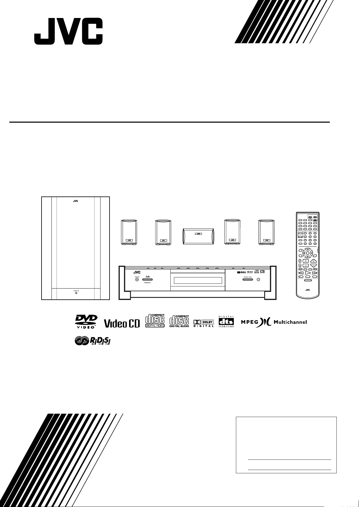
DVD DIGITAL CINEMA SYSTEM
TH-A9R
Consists of XV-THA9R, SP-PWA9, SP-XCA9, and SP-XSA9
SP-XSA9
SP-XCA9
DVD DIGITAL CINEMA SYSTEM TH-A9R
SP-XSA9
CONTROL
RDS DISPLAY
AUX
TITLE
ZOOM
VCR
SLEEP
SETTING
PLAY
MODE
THEATER
POSITION
TV
PTY
REC
FM/AM
DVD
DECODE
SUBTITLE
TIME
DIGEST
CHOICEANGLERETURN
SUBWOOFER
CENTER
REAR-L
REAR-R
TV RETURN FM MODE
EON SELECT
ENTER
EON
PTY SEARCH
CHANNELTV VOL VOLUME
TV/VIDEO
MUTING
/REW
PLAY
TUNING
STOP
DVD MENU
STANDBY/ON
AUDIOTV
VCR
AUDIO
DISPLAY
SOUND
EFFECT
TEST
100+
DVD
RDS
+PTY
DSP
MODE
F.SEARCHB.SEARCH
FF/
UPDOWN
PAUSE
STROBEMEMORY
SP-PWA9
INSTRUCTIONS
XV-THA9R
RM-STHA9R
DVD CINEMA SYSTEM
For Customer Use:
Enter below the Model No. and Serial
No. which are located either on the rear,
bottom or side of the cabinet. Retain this
information for future reference.
Model No.
Serial No.
LVT0562-004A
[B]
Page 2
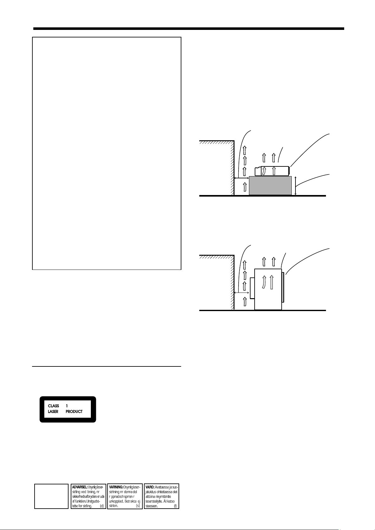
Warnings, Cautions and Others
Spacing 15 cm or more
Wall or
obstructions
Stand height
5 cm or more
Front
XV-THA9R
Floor
Spacing 15 cm or more
Wall or
obstructions
SP-PWA9
Front
Floor
EnglishEnglishEnglishEnglishEnglishEnglishEnglish
IMPORTANT for the U.K.
DO NOT
the plug fitted is not suitable for the power points in your
home or the cable is too short to reach a power point,
then obtain an appropriate safety approved extension
lead or consult your dealer.
BE SURE
approved type, as originally fitted.
If nonetheless the mains plug is cut off ensure to
remove the fuse and dispose of the plug immediately, to
avoid a possible shock hazard by inadvertent
connection to the mains supply.
If this product is not supplied fitted with a mains plug
then follow the instructions given below:
IMPORTANT.
DO NOT
marked with the letter E or by the safety earth symbol or
coloured green or green-and-yellow.
The wires in the mains lead on this pr od uct are
coloured in accordance with the following code:
As these colours may not correspond with the coloured
markings identifying the terminals in your plug proceed
as follows:
The wire which is coloured blue must be connected to
the terminal which is marked with the letter N or
coloured black.
The wire which is coloured brown must be connected to
the terminal which is marked with the letter L or
coloured red.
cut off the mains plug from this equipment. If
to replace the fuse only with an identical
make any connection to the terminal which is
Blue : Neutral
Brown : Live
Caution: Proper Ventilation
To avoide risk of electric shock and fire and to protect from
damage.
Locate the apparatus as follows:
Front: No obstructions and open spacing.
Sides: No obstructions in 3 cm from the sides.
Top: No obstructions in 5 cm from the top.
Back: No obstructions in 15 cm from the back
Bottom: No obstructions, place on the level surface.
XV-THA9R
SP-PWA9
IF IN DOUBT - CONSULT A COMPETENT ELECTRICIAN.
Caution ––
Disconnect the XV-THA9R and SP-PWA9 main
plugs to shut the power off completely. The üý
button on the XV-THA9R in any position do not disconnect the meins line. The power can be remote
controlled.
CAUTION
To reduce the risk of electrical shocks, fire, etc.:
1. Do not remove screws, covers or cabinet.
2. Do not expose this appliance to rain or moisture.
üüüü
button!
IMPORTANT FOR LASER PRODUCTS
PRODUCTION OF LABELS
1 CLASSIFICATION MARK, PLACED ON REAR
ENCLOSURE
1. CLASS 1 LASER PRODUCT
2.
CAUTION:
open and interlock failed or defeated. Avoid direct exposure to beam.
3.
CAUTION:
serviceable parts inside the Unit; leave all servicing to
qualified service personnel.
2 WARNING LABEL, PLACED INSIDE THE UNIT
CAUTION:
radiation when open and
interlock failed or defeated.
AVOID DIRECT EXPOSURE
TO BEAM. (e)
G-1
G-1
G-1G-1
Visible and invisible laser radiation when
Do not open the top cover. There are no user
Invisible laser
CAUTION:
1. Do not block the ventilation openings or holes. (If the
ventilation openings or holes are blocked by a newspaper or cloth, etc., the heat may not be able to get out.)
2. Do not place any naked flame sources, such as lighted
candles, on the apparatus.
3. When discarding batteries, environmental problem s
must be considered and local rules or laws governing the
disposal of these batteries must be followed strictly.
4. Do not use this apparatus in a bathroom or places with
water.
Also do not place any containers filled with water or liquids (such as cosmetics or medicines, flower vases, potted plants, cups, etc.) on top of this apparatus.
Page 3

■■
Table of Contents
Getting Started ......................................................2
Important cautions ................................................................ 2
Safety precautions................................................................. 2
Checking the supplied accessories........................................2
System outline ......................................................3
Installation.............................................................4
To hang satellite speakers from the wall .............................. 4
About discs ...........................................................5
Playable disc types................................................................ 5
Disc structure ........................................................................ 5
Video CDs with Playback Control function .........................5
Connections..........................................................6
Connecting the FM and AM (MW) antennas....................... 6
Connecting the powered sub-woofer.................................... 6
Connecting the TV................................................................ 6
Connecting the TV with the SCART connector...................7
Connecting speakers .............................................................8
Connecting an audio component........................................... 9
Connecting the power cord................................................. 10
Putting batteries in the remote control................................ 10
Parts Identification ..............................................11
Principles of operation ........................................14
Operation with the remote control...................................... 14
On-screen displays.............................................................. 15
Preventing screen burn-out with the screen saver
[SCREEN SAVER] ............................................................ 16
Basic operations .................................................17
To turn the system power supply ON and OFF (standby).. 17
To turn TV power ON and OFF ......................................... 17
Adjusting volume [VOLUME]........................................... 17
Sub-woofer volume control and phase setting.................... 18
Muting the sound [MUTING]............................................. 18
Selecting the source to play ................................................ 18
Changing the decode mode [DECODE]............................. 19
Audio channel display indicator ......................................... 19
Using the Sleep Timer [SLEEP]......................................... 20
Using the DSP Modes [DSP MODE]................................. 20
Using the DVD player .........................................22
To turn on the system and TV ............................................ 22
To insert a disc.................................................................... 22
To play a disc...................................................................... 23
Pausing................................................................................ 24
Fast forward and backward................................................. 24
Locating the beginning ....................................................... 24
Resuming playback............................................................. 25
Selecting playback from the DVD menu............................ 25
Selecting the location to view from the Video CD menu... 26
To specify the title, chapter, or track number for
playback.............................................................................. 26
To play from the beginning of a title, chapter, or track...... 27
To specify the chapter number for playback
[CHAP. SEARCH] ................... .......................................... 27
To specify the time for playback [TIME SEARCH]..........27
To select the screen for playback from the digest screen
[DIGEST]............................................................................ 28
To advance the picture one frame at a time........................ 29
Slow-Motion Playback [SLOW] ........................................ 29
To display Continuous Photos [STROBE]......................... 30
Zooming a scene [ZOOM].................................................. 31
Changing the Subtitle Language [SUBTITLE]..................31
Changing the audio language or sound [AUDIO] .............. 32
Changing the audio channel [AUDIO] ............................... 32
Viewing from Multiple Angles [ANGLE].......................... 33
Selecting the Picture Character [THEATER POSITION].. 34
Repeating a current title, chapter or track, or all tracks
[REPEAT]........................................................................... 34
Repeating a desired part [A-B REPEAT]............................35
Programming the Playing Order [PROGRAM] ..................36
Random Play [RANDOM]..................................................37
To check the DVD function status ......................................37
To check the disc information.............................................38
To check the time information ............................................38
Receiving radio broadcasts.................................40
Tuning in stations manually ................................................40
Using preset tuning.... .................................. ........................40
Selecting the FM reception mode........................................41
Beat cut................................................................................41
Using the RDS (Radio Data System) to receive
FM stations..........................................................................42
What information can RDS signals provide?......................42
Searching for a program by PTY codes ..............................42
Switching to a broadcast program of your choice
temporarily ..........................................................................43
Preference settings.............................................44
Using the preference setting menus.....................................44
LANGUAGE MENU settings...............................45
Choosing menu language ....................................................45
Choosing audio language ....................................................45
Choosing subtitle language .................................................45
Choosing on-screen language..............................................45
DISPLAY MENU settings....................................46
Select monitor type..............................................................46
Screen saver settings ...........................................................46
On-screen guide settings .....................................................46
SYSTEM MENU setting......................................47
AUTO STANDBY..............................................................47
RESUME.............................................................................47
AV COMPULINK MODE..................................................47
Limiting playback by children..............................48
To set Parental Lock for the first time
[PARENTAL LOCK]..........................................................48
To temporarily release the Parental lock.............................49
Amplifier settings.................................................50
Basic operation for setting amplifier...................................50
Setting balance ....................................................................50
Setting tone..........................................................................51
Setting speaker size .............................................................51
Adjusting delay time ................. ........................................ ..51
Adjusting crossover.............................................................52
Adjusting LFE attenuator....................................................52
Adjusting dynamic range.....................................................52
Sound settings .................................................. ..53
Adjusting sub-woofer level.................................................53
Adjusting speaker level .......................................................53
Adjusting DSP effect...........................................................54
Operating Other Manufacturers’ Video
Equipment...........................................................55
Care and handling of discs..................................57
How to handle discs ............................................................57
Troubleshooting ..................................................58
Specifications......................................................59
EnglishEnglishEnglishEnglishEnglishEnglishEnglish
1111
Page 4
■■
Getting Started
Important cautions
EnglishEnglishEnglishEnglishEnglishEnglishEnglish
Installation of the unit
• Select a place which is level, dry and neither too hot nor too
cold between 5°C and 35°C (41°F and 95°F).
• Leave sufficient distance between the unit and the TV.
• Do not use the unit in a place subject to vibrations.
Power cord
• Do not handle the power cord with wet hands!
• A small amount of power 1.9 W is always consumed while the
power cord is connected to the wall outlet. (center unit only)
• When unplugging the unit from the wall outlet, always pull the
plug, not the power cord.
To prevent malfunction of the unit
• There are no user-serviceable parts inside. If anything goes
wrong, unplug the power cord and consult your dealer.
• Do not insert any metallic object into the unit.
• Do not use any non-standard shape disc available on the
market, because it may damage the unit.
• Do not use a disc with tape, seals, or paste on it, because
damage to the unit may result.
Note about the copyguard system
• The DVD disc is protected by the copyguard system. When you
connect the unit to your VCR directly, the copyguard system
activates and the picture may not be played back correctly.
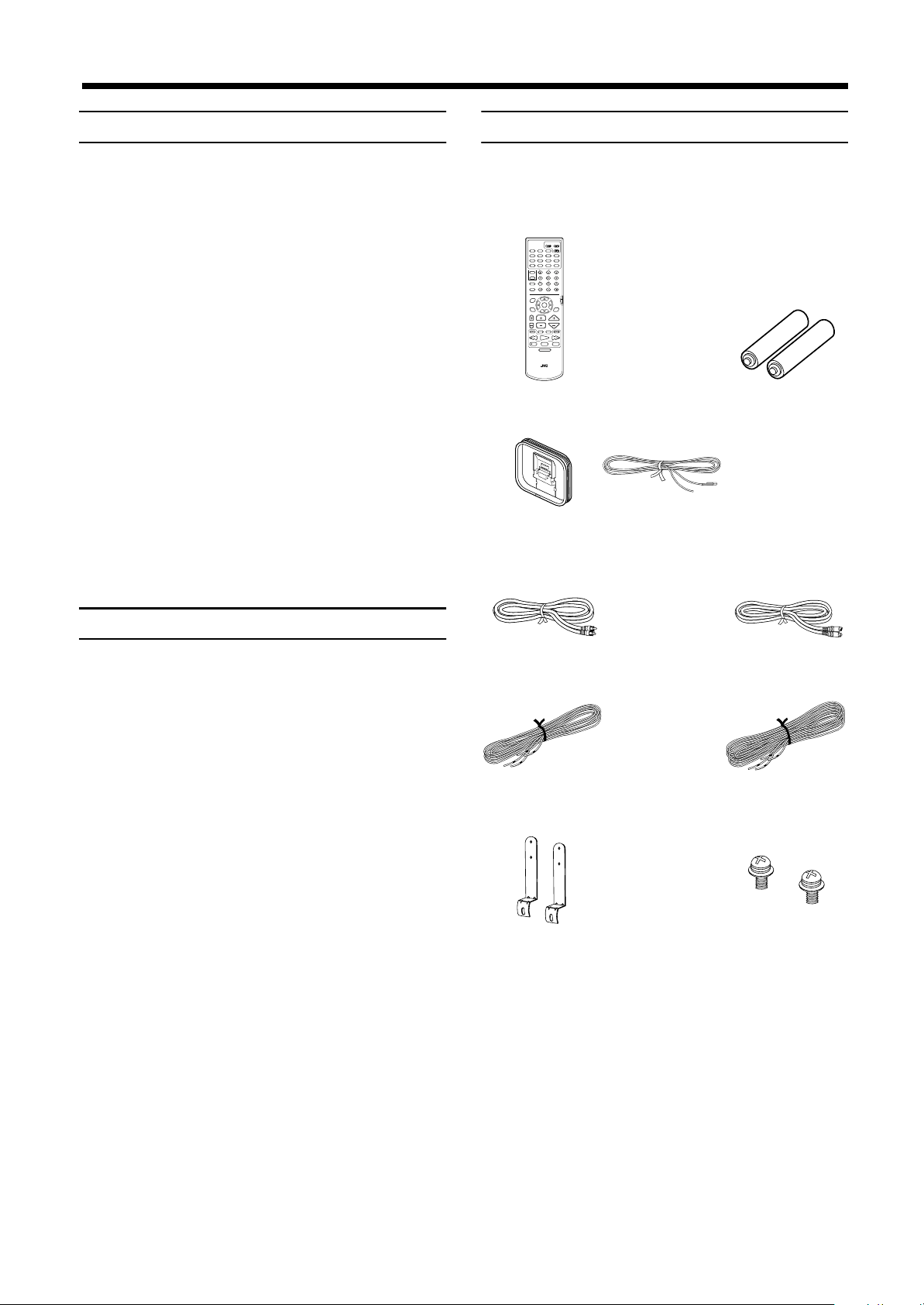
Checking the supplied accessories
Check to be sure you have all of the following items, which are
supplied with the unit.
The number in the parentheses indicates quantity of the pieces
supplied.
STANDBY/ON
AUDIOTV
VCR
DVD
AUX
FM/AM
DECODE
SUBTITLE
TITLE
AUDIO
TIME
DIGEST
ZOOM
DISPLAY
CHOICEANGLERETURN
SOUND
SUBWOOFER
EFFECT
CONTROL
VCR
CENTER
TEST
TV
REAR-L
SLEEP
REAR-R
SETTING
TV RETURN FM MODE
100+
EON SELECT
DVD
PLAY
MODE
RDS
ENTER
PTY
-
+PTY
EON
THEATER
DSP
POSITION
MODE
RDS DISPLAY
PTY SEARCH
CHANNELTV VOL VOLUME
TV/VIDEO
MUTING
F.SEARCHB.SEARCH
/REW
FF/
PLAY
UPDOWN
TUNING
PAUSE
REC
STOP
STROBEMEMORY
DVD MENU
RM-STHA9R
DVD CINEMA SYSTEM
Remote control (1) Batteries (2)
AM (MW) Loop
Antenna (1)
FM Antenna (1) AC Power Cord (1)
Safety precautions
Avoid moisture, water and dust
Do not place your unit in moist or dusty places.
Avoid high temperatures
Do not expose the unit to direct sunlight or place it near a heating
device.
When you’re away
When away on travel or otherwise for an extended period of time,
remove the plug from the wall outlet.
Do not block the vents
Blocking the vents may damage the unit.
Care of the cabinet
When cleaning the unit, use a soft cloth and follow the relevant
instructions on the use of chemically-coated cloths. Do not use
benzene, thinner or other organic solvents and disinfectants. These
may cause deformation or discoloring.
If water gets inside the unit
Turn off the power switch and remove the plug from the wall
outlet, then call the store where you made your purchase. Using the
unit in this state may cause a fire or electrical shock.
Video Cable (1) System Cable (1)
Speaker Cord 5 m
(16.4 ft) (3)
Satellite speaker wall
Speaker Cord 10m
(32.8 ft) (2)
Screws (2)*
bracket (2)*
* Speaker wall brackets and screws are packed
together with the satellite speakers.
Avoid getting your hand caught in the disc
cover
Getting caught may injure your hand.
2222
Page 5
■■
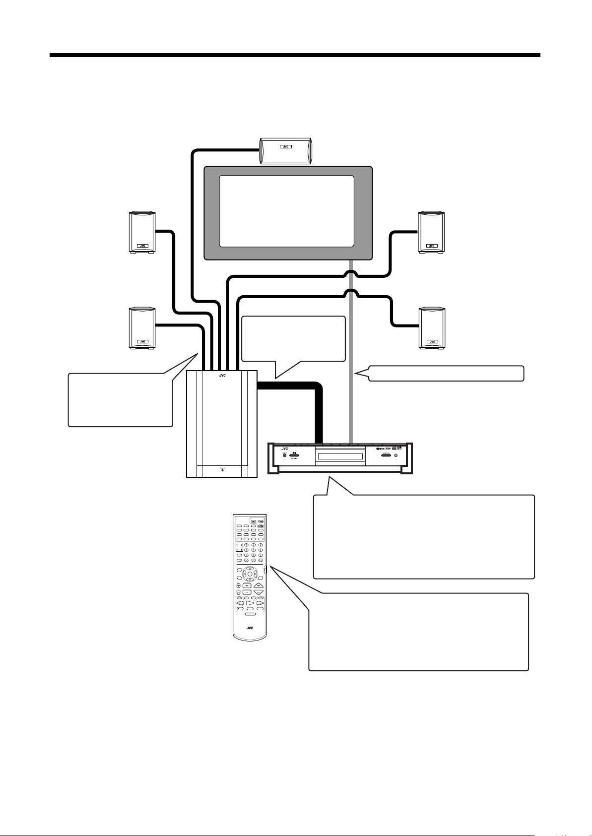
System outline
This system consists of the unit containing a DVD player, a radio, and a pre-amp, as well as the powered sub-woofer, the center speaker,
and four satellite speaker units.
It provides a fully functional DVD cinema system by simply connecting to a TV set.
Center speaker
(SP-XCA9)
Front left speaker
Satellite speaker
(SP-XSA9)
Rear left speaker
Satellite speaker
(SP-XSA9)
The center speaker and the
satellite speakers are
connected to the powered
sub-woofer.
Powered sub-woofer
(SP-PWA9)
TV
The center unit and
powered sub-woofer are
connected with the system
cable.
DVD DIGITAL CINEMA SYSTEM TH-A9R
Front right speaker
Satellite speaker
(SP-XSA9)
Rear right speaker
Satellite speaker
(SP-XSA9)
The TV is connected to the center unit.
Center unit (XV-THA9R)
AUX
TITLE
ZOOM
CONTROL
VCR
TV
SLEEP
SETTING
PLAY
MODE
PTY
-
THEATER
POSITION
RDS DISPLAY
/REW
REC
DVD CINEMA SYSTEM
STANDBY/ON
DVD
FM/AM
DECODE
SUBTITLE
TIME
DIGEST
CHOICEANGLERETURN
SUBWOOFER
CENTER
REAR-L
REAR-R
TV RETURN FM MODE
EON SELECT
ENTER
EON
PTY SEARCH
CHANNELTV VOL VOLUME
TV/VIDEO
MUTING
PLAY
TUNING
STOP
DVD MENU
RM-STHA9R
AUDIOTV
VCR
AUDIO
DISPLAY
SOUND
EFFECT
TEST
100+
DVD
RDS
+PTY
DSP
MODE
F.SEARCHB.SEARCH
FF/
UPDOWN
PAUSE
STROBEMEMORY
Contains a DVD player, radio, and preamp (volume
control, tone control), together with a Dolby digital
decoder and DTS digital surround decoder for Dolby
Surround and DTS Digital Surround effects.
For some music software, the DAP mode offers the
expanded sound field.
This system is capable of most operations.
It may also be used to operate JVC TVs and VCRs, as well
as TVs and VCRs from other manufacturers. Note that the
remote control unit must be programmed with the correct
EnglishEnglishEnglishEnglishEnglishEnglishEnglish
settings when using products from other manufacturers.
3333
Page 6
■■
Bracket
Screw
Normal position
Tilting the speaker
Installation
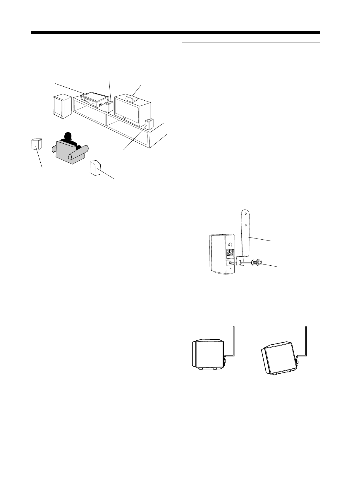
The following shows an example of the system installation.
EnglishEnglishEnglishEnglishEnglishEnglishEnglish
System setting example
Satellite speaker
Center unit
Powered
sub-woofer
Satellite speaker
(rear left speaker)
(front left speaker)
Satellite speaker (front
right speaker)
Satellite speaker
(rear right speaker)
The rear speakers are placed
behind the listening position.
Center speaker
To hang satellite speakers from the
wall
Use the supplied bracket to fix satellite speakers to the wall.
CAUTION: ATTACHING THE BRACKETS
ON THE WALL
When attaching the brackets on the wall, have them
attached to the wall by a qualified person.
DO NOT attach the brackets on the wall by yourself to
avoid an unexpected damage of their falling from the
wall, caused by incorrect attachment or weakness in
the wall.
Location of attachment to wall:
Care is required in selecting a location for attaching
satellite speakers to the wall. Injury to personnel, or
damage to equipment, may result if the speakers are
attached in a location which interferes with daily
activities.
Attaching speakers to the bracket
Use the screw supplied to attach the speaker
1
to the bracket.
CAUTIONS:
• For safety reasons, always ensure that there is
sufficient place behind the powered sub-woofer.
• If the front and rear speakers are placed on the
furniture etc., always ensure that they are level.
Adjusting the angle of the satellite speakers
2
The angle of the speaker may be adjusted along the channel in
the bracket.
When adjusting the angle, loosen the screw slightly, make the
adjustment, and then tighten the screw firmly.
4444
CAUTION:
If the screw is not tightened firmly, it may cause injury
to personnel or damage to equipment.
Page 7
■■
About discs
Playable disc types
Playable and non-playable disc types are as follows:
Playable discs
DVD
The DVD Logo is a trademark.
Video CD
Non-playable discs
• DVD-ROM • DVD-RAM • DVD-R • DVD-RW
• CD-R*• CD-ROM • PHOTO CD • CD-RW*
* Audio formatted CD-R and CD-RW can be played.
• Playing back discs list as “Non-playable discs” above may
generate noise and damage speakers.
• Only audio can be played for CD-G, CD-EXTRA and CD
TEXT.
Notes on DVD discs
• DVD players and DVD discs have their own Region Code
numbers. This unit only can play back DVD discs whose
Region Code numbers include “2”.
Audio CD
Examples of playable DVD discs:
• This unit accommodates discs for the PAL system.
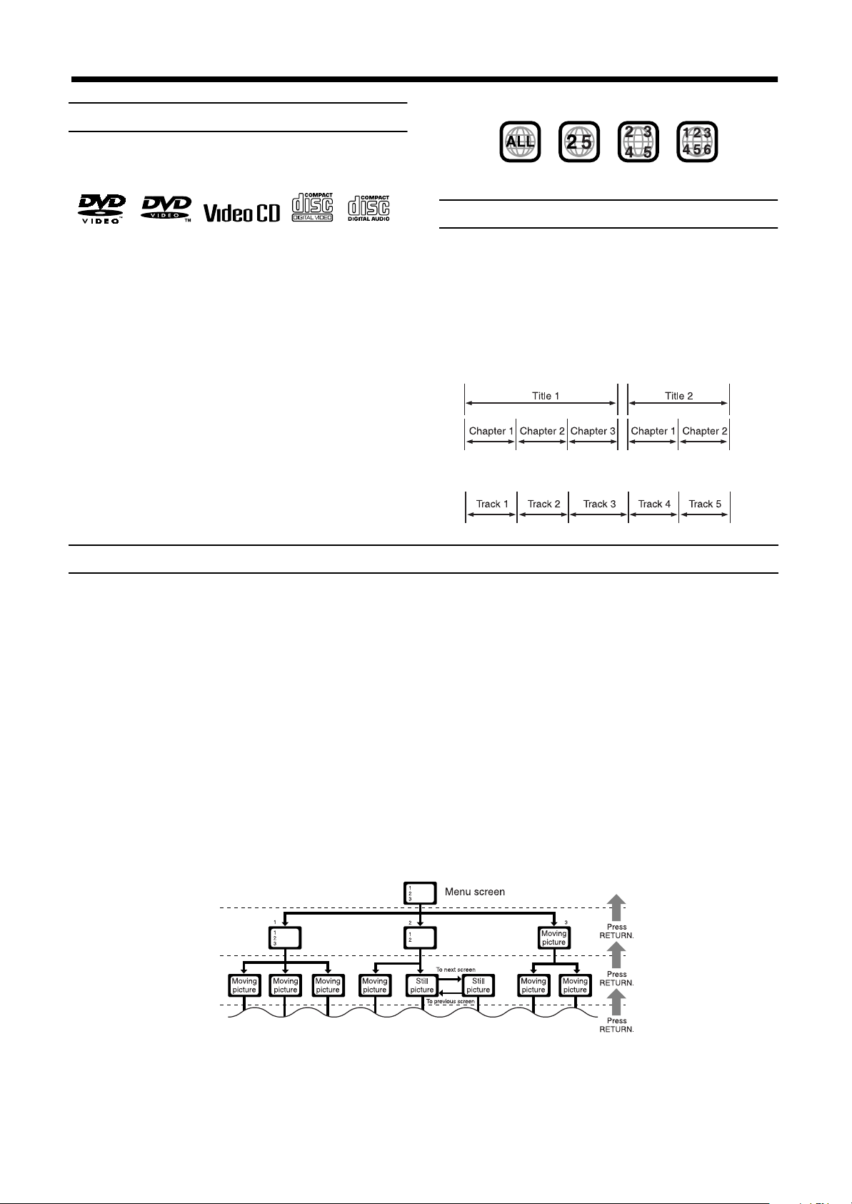
Disc structure
A DVD disc is comprised of “titles”, while an Audio CD or Video
CD is comprised of “tracks”. Each title may be divided into some
“chapters”. For example, if a DVD disc contains some movies,
each movie may have its own title number, and each movie may be
divided into some chapters. In a DVD karaoke disc, each song
usually has its own title number and does not have chapters. In
general, each title has independent content, while each chapter in
the same title has continuity.
Example: DVD disc
Example: Audio CD/Video CD
Video CDs with Playback Control function
What is Playback Control function?
The Playback Control function, allows you to enjoy menu-driven operation and high-resolution still images which have a resolution four
times greater than moving pictures.
• Menu-driven playback
You can interact with the screen using a menu display to select and play an entry.
• High-resolution still image display
You can display high-quality images four times clearer than moving pictures.
A selection menu is displayed when you start playing a Video CD with the Playback Control feature. The selection menu shows a list of
numbers for selection. Some discs may show moving pictures or a divided screen.
1. When a list of numbers is displayed, selecting a number shows its contents.
2. When “3333” or “SELECT” is displayed on the television screen, pressing this button jumps to the specific picture.
3. When the selection menu is re-displayed after you have played your selection, selecting a number again replays its contents.
(Some discs may show the menu screen several times.)
When ¢ and 4 are shown, pressing “NEXT” or “PREV” can change the selection menu.
4. After playback, press RETURN to go back to the previous screen.
To stop playback, press STOP.
EnglishEnglishEnglishEnglishEnglishEnglishEnglish
Note:
• When a menu is displayed for a long time (about ten minutes), the screen background automatically gets dark to prevent
screen burn-in while the setting is suspended.
5555
Page 8
■■
MAX
MIN
REVERSR
NOMAL
PHASE
SUB WOOFER
CONNECTOR
FROM XV - THA9
FRONT SPEAKERS
CENTER
SPEAKER
REAR SPEAKERS
SPEAKER IMPEDANCE
SPEAKER IMPEDANCE
CAUTION :
SPEAKER IMPEDANCE
CAUTION :
CAUTION :
LEFT
RIGHT
VOLUME
CONNECTOR
TO SP-PWA9
AV
COMPU LINK
AUX IN
ANTENNA
AM
LOOP
AM EXT
S-VIDEO AV
COMP.
Y/C
VIDEO
VIDEO OUT AV OUT
RL
CONNECTOR
FROM XV - THA9
CONNECTOR
TO SP-PWA9
Center unit (XV-THA9R)
Ensure that the £ mark on the
plug faces down.
System cable
(supplied)
Ensure that the £ mark
on the plug faces to the
right.
Powered sub-woofer
(SP-PWA9)
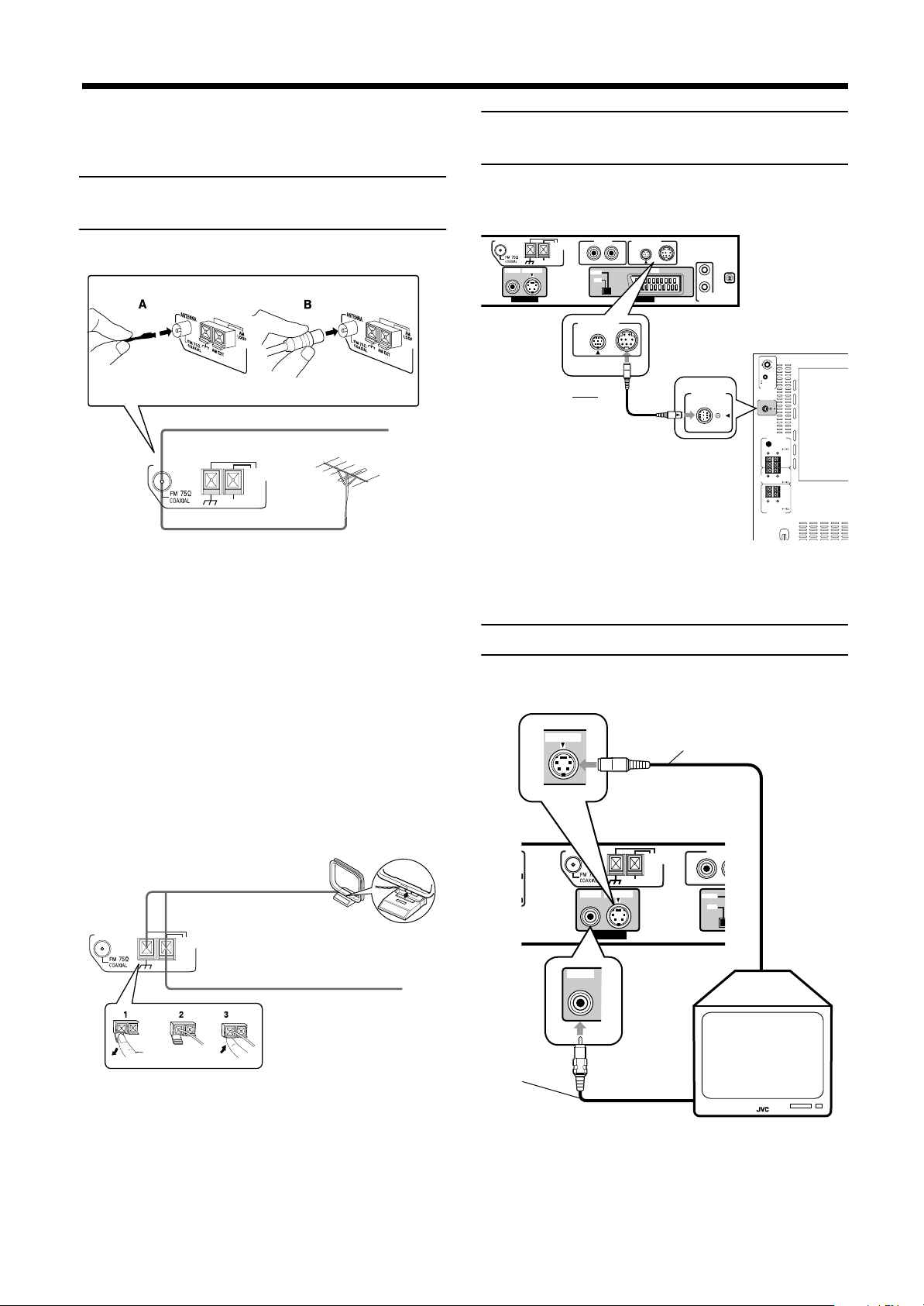
S-VIDEO
VIDEO
S-video cable (not supplied)
Connect to the TV if it has an S-video
input (for higher image quality). Connect
the cables with the ∞ mark facing up.
Center unit (XV-THA9R)
Video cable
(supplied)
To composite
video input
To S-video
input
Connections
CAUTION:
• Make all connection before plugging the system in an
EnglishEnglishEnglishEnglishEnglishEnglishEnglish
AC outlet.
Connecting the FM and AM (MW)
antennas
FM antenna connections
A.
ANTENNA
B.
A.Using the supplied FM antenna
The FM antenna provided can be connected to the FM 75 Ω
COAXIAL terminal as temporary measure.
FM Antenna
Extend the supplled FM antenna horizontally.
AM
LOOP
AM EXT
Outdoor FM Antenna Cable
Connecting the powered subwoofer
Use the supplied system cable to connect the powered sub-woofer
(SP-PWA9).
CAUTUON:
Use the system cable provided for attaching the
center unit and the sub-woofer.
B.Using the standard type connector (Not
supplied)
A standard type connector should be connected to the FM 75 Ω
COAXIAL terminal.
Note:
• If reception is poor, connect the outdoor antenna.
Before attaching the 75 Ω coaxial cable (the kind with a
round wire going to an outdoor antenna), disconnect the
supplied FM antenna.
AM (MW) antenna connections
Turn the loop until you have the best reception.
ANTENNA
Notes:
• Make sure the antenna conductors do not touch any other
terminals, connecting cords and power cord. This could
cause poor reception.
• If reception is poor, connect an outdoor single vinylcovered wire to the AM EXT terminal. (Keep the AM (MW)
loop antenna connected.)
6666
AM (MW) Loop Antenna
AM
LOOP
AM EXT
Outdoor single vinyl-covered wire
Connecting the TV
Connect the TV to view video images from the unit.
ANTENNA
VIDEO
VIDEO OUT
AM EXT
S-VIDEO
AM
LOOP
AUX I
R
COMP.
Y/C
Page 9
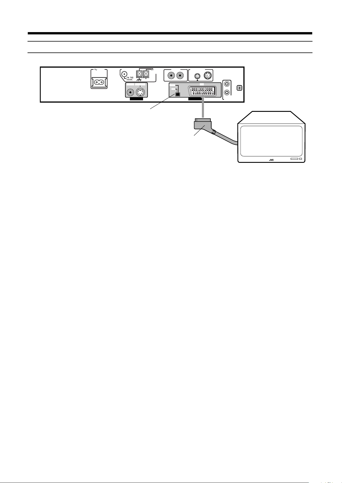
Connecting the TV with the SCART connector
Connections
Connections
ConnectionsConnections
AC IN
ANTENNA
VIDEO
VIDEO OUT AV OUT
AM
LOOP
AM EXT
S-VIDEO AV
AUX IN
RL
COMP.
Y/C
CONNECTOR
TO SP-PWA9
AV
COMPU LINK
COMP.-Y/C switch
SCART Cable
(Not supplied)
Connect the unit’s AV OUT connector with your TV’s SCART connector using an optional SCART cable.
• Set the COMP.-Y/C switch correctly according to your TV. If the TV only accommodates the regular (composite) video signal, set the
switch to “COMP”. If the TV accommodates the Y/C signal, set the switch to Y/C so that you can enjoy better-quality pictures.
Note:
On the rear panel SCART cable is indicated as “AV OUT”. However, this terminal is designed as video output. So,
no sound comes out.
EnglishEnglishEnglishEnglishEnglishEnglishEnglish
7777
Page 10

Connections
MAX
MIN
REVERSR
NOMAL
PHASE
SUB WOOFER
CONNECTOR
FROM XV - THA9
FRONT SPEAKERS
CENTER
SPEAKER
REAR SPEAKERS
SPEAKER IMPEDANCE
SPEAKER IMPEDANCE
CAUTION :
SPEAKER IMPEDANCE
CAUTION :
CAUTION :
LEFT
RIGHT
VOLUME
Connections
ConnectionsConnections
Connecting speakers
EnglishEnglishEnglishEnglishEnglishEnglishEnglish
Connect the satellite speakers and center speaker to the terminals on the powered sub-woofer using the speaker cords supplied.
Labels are attached to the speaker cords to indicate the speaker and terminal to which each is to be connected.
• The four satellite speakers may be used at either front or rear.
• Ensure that the left and right speakers are connected to left and right respectively, and that they are connected with the correct polarity
(+ve, –ve). The white speaker cord connects to the + terminal, and the black speaker cord connects to the – terminal.
Twist and remove the insulation at the end of each speaker cord.
FRONT SPEAKERS
SPEAKER IMPEDANCE
CAUTION :
LEFT
RIGHT
CENTER
SPEAKER
CAUTION :
SPEAKER IMPEDANCE
Connecting the front speakers
Connect the right speaker to the FRONT SPEAKERS RIGHT
terminal.
Connect the left speaker to the FRONT SPEAKERS LEFT
terminal.
CAUTION :
SPEAKER IMPEDANCE
REAR SPEAKERS
Connecting the rear and center speakers
Connect the right rear speaker to the REAR SPEAKERS RIGHT
terminals.
Connect the left rear speaker to the REAR SPEAKERS LEFT
terminals.
Connect the center speaker to the CENTER SPEAKER terminals.
Front right speaker
Front left speaker
Speaker cord
(5 m) (16.4 ft)
FRONT RIGHT
FRONT SPEAKERS
SPEAKER IMPEDANCE
CAUTION :
FRONT LEFT
Fold the end of the cord to
avoid short-circuit. Then,
Black
LEFT
RIGHT
while pushing the lever of
the speaker terminal,
insert the folded end of
the cord into the terminal.
CENTER
SPEAKER
CAUTION :
SPEAKER IMPEDANCE
White
Black
Rear right speaker
CAUTION :
SPEAKER IMPEDANCE
REAR SPEAKERS
Note:
• Mixing up the polarity of the speaker cords can reduce the stereo effect and sound quality.
Center speaker
FRONT SPEAKERS
CENTER
SPEAKER IMPEDANCE
CENTER
SPEAKER IMPEDANCE
SPEAKER
REAR RIGHT
CAUTION :
SPEAKER IMPEDANCE
REAR SPEAKERS
Speaker cord
(10 m) (32.8 ft)
CAUTION :
LEFT
RIGHT
CAUTION :
REAR LEFT
Rear left speaker
Speaker cord
(5 m) (16.4 ft)
White
8888
Page 11

Connecting an audio component
You can connect an analog audio component, such as VCR, TV and MD recorder to this system.
Refer also to the manuals supplied with your components.
Use the cable with RCA pin plugs (not supplied).
Connect the white plug to the left jack, and the red plug to the right jack.
Connections
Connections
ConnectionsConnections
VCR
TV
AC IN
ANTENNA
VIDEO
VIDEO OUT AV OUT
AM
LOOP
AM EXT
S-VIDEO AV
AUX IN
RL
COMP.
Y/C
AUX IN
RL
Audio output
Audio output
CONNECTOR
TO SP-PWA9
AV
COMPU LINK
MD Recorder
Audio output
CAUTION:
If you connect a sound-enhancing device such as a graphic equalizer between the source components and the
center unit, the sound output through this system may be distorted.
EnglishEnglishEnglishEnglishEnglishEnglishEnglish
9999
Page 12
Connections
U
123
Connections
ConnectionsConnections
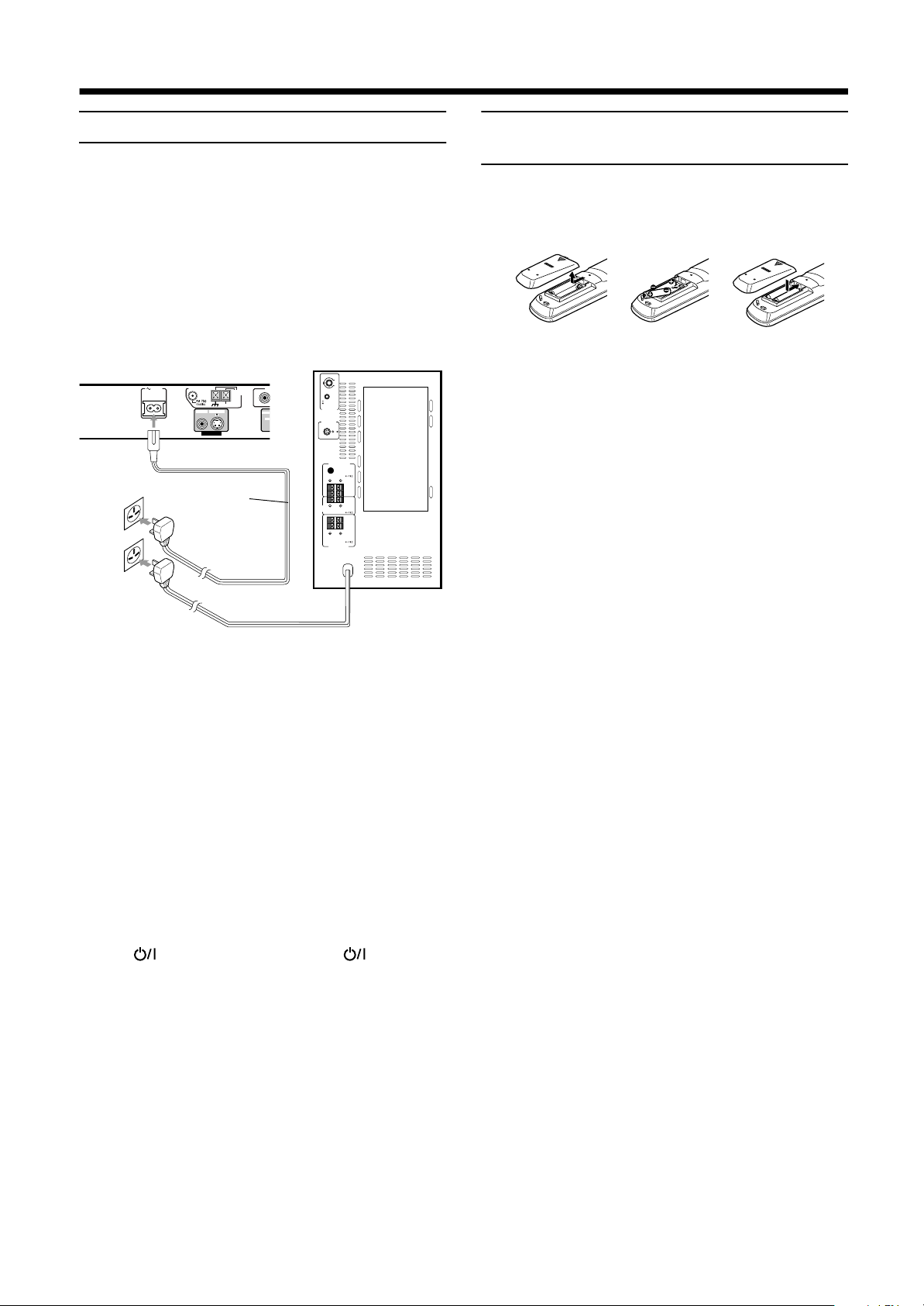
Connecting the power cord
EnglishEnglishEnglishEnglishEnglishEnglishEnglish
Before plugging the center unit and powered sub-woofer into an
AC outlets, make sure that all connections have been made.
Plug the power cord into an AC outlet.
The red STANDBY lamp on the center unit lights when the power
cord is plugged in.
Keep the power cord away from the connecting cables and the
antenna cable. The power cord may cause noise or screen
interference.
We recommend that you use a coaxial cable to connect the FM
outdoor antenna, since it is well-shielded against interference.
Center unit
AM EXT
A
AM
LOOP
R
COMP.
Y/C
AC IN
ANTENNA
S-VIDEO
VIDEO
VIDEO OUT
AC power cord
CAUTIONS:
• Do not touch the power cord with wet hands.
• Do not pull on the power cord to unplug the cord.
When unplugging the cord, always grasp the plug so
as not to damage the cord.
Powered sub-woofer
VOLUME
MAX
MIN
PHASE
REVERSR
NOMAL
SUB WOOFER
CONNECTOR
FROM XV - THA9
FRONT SPEAKERS
CAUTION :
SPEAKER IMPEDANCE
LEFT
RIGHT
CENTER
CAUTION :
SPEAKER IMPEDANCE
SPEAKER
CAUTION :
SPEAKER IMPEDANCE
REAR SPEAKERS
Putting batteries in the remote
control
Before using the remote control, put two supplied batteries first.
When using the remote control, aim the remote control directly at
the remote sensor on the center unit.
On the back of the remote control, remove the
1
battery cover.
Insert batteries. Make sure to match the
2
polarity: (+) to (–).
Replace the cover.
3
• If the range or effectiveness of the remote control decreases,
replace the batteries. Use two R6P (SUM-3)/AA (15F) type
dry-cell batteries.
CAUTIONS:
Follow these precautions to avoid leaking or cracking
cells:
• Place batteries in the remote control so they match
the polarity: (+) to (–).
• Use the correct type of batteries. Batteries that look
similar may differ in voltage.
• Always replace both batteries at the same time.
• Do not expose batteries to heat or flame.
Notes:
• The preset settings such as preset channel and sound
adjustment may be erased in a few days in the following
cases:
– When you unplug the power cord.
– When a power failure occurs.
• The speakers will not produce any sound if the powered
sub-woofer power cord is removed from the AC outlet
while the center unit is turned on.
In this case power will not come on even when the
powered sub-woofer power cord is plugged in the AC
outlet.
Press on the center unit, or AUDIO on the
remote control to turn power on. This will turn the powered
sub-woofer on and sound will be emitted from the
speakers.
10
10
1010
Page 13
■■
Become familiar with the buttons and controls on the center unit and powered sub-woofer before use. Refer to the pages in parentheses for
details.
Parts Identification
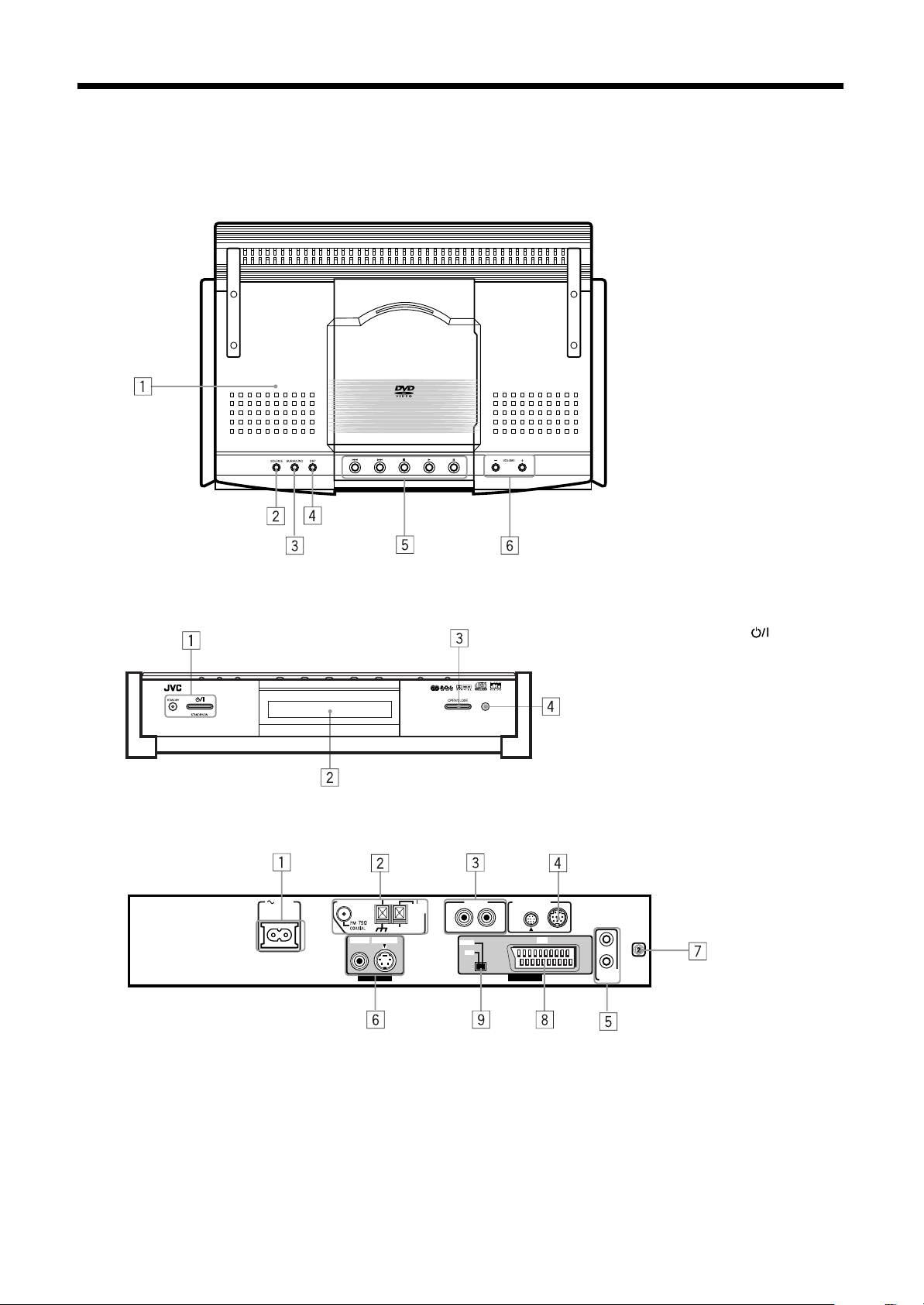
Center unit
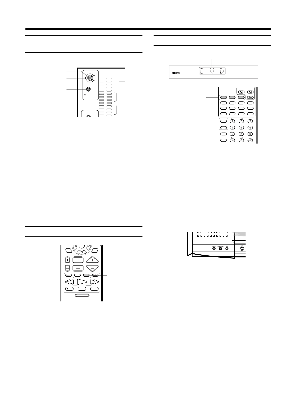
Front panel (top view)
1 Disc cover (22)
2 SOURCE button (18)
3 SURROUND button (21)
4 DSP mode button (21)
5 DVD control buttons (23, 24,
25)
6 VOLUME +/– button (17)
Front panel (front view)
Rear panel
1 AC IN socket (10)
2 Antenna terminals (6)
3 AUX IN terminals (9)
4 Connector for powered sub-woofer (6)
5 AV COMPU LINK terminals (47)
6 Video output terminals (6, 7)
7 Region code number (5)
8 AV OUT terminal
9 Switch for selecting video output of AV OUT
DVD DIGITAL CINEMA SYSTEM TH-A9R
AC IN
ANTENNA
VIDEO
VIDEO OUT AV OUT
AM
LOOP
AM EXT
S-VIDEO AV
AUX IN
RL
COMP.
Y/C
CONNECTOR
TO SP-PWA9
1 STANDBY/ON button
and STANDBY lamp (17)
2 Display window
3 OPEN/CLOSE button (22)
4 Remote sensor
AV
COMPU LINK
EnglishEnglishEnglishEnglishEnglishEnglishEnglish
11
11
1111
Page 14
Parts Identification
1
Parts Identification
Parts IdentificationParts Identification
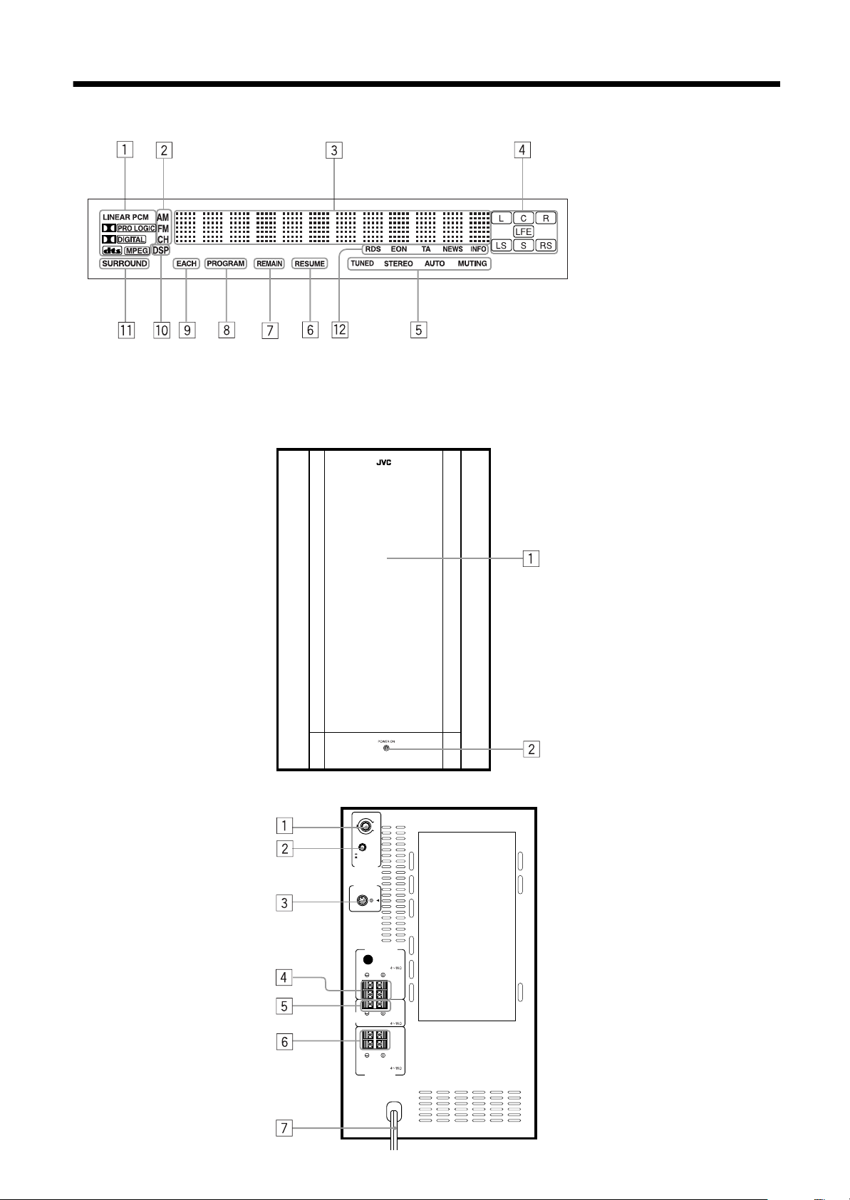
Display window
EnglishEnglishEnglishEnglishEnglishEnglishEnglish
Powered sub-woofer
(Front)
Decode mode indicator
2 Radio indicator (40, 41)
3 Multi-information window
Displays time, status
information, etc.
4 Audio channel indicator (19)
5 Radio reception mode indicator
(40, 41)
6 RESUME indicator (25)
7 REMAIN indicator (Timer
indicator) (39)
8 PROGRAM indicator (36)
9 EACH indicator (Timer
indicator) (39)
p DSP indicator (21)
q SURROUND indicator (21)
w RDS reception mode indicator
(42)
1 Speaker
2 POWER ON lamp (17)
(Rear)
12
12
1212
SUB WOOFER
CONNECTOR
FROM XV - THA9
CENTER
SPEAKER
VOLUME
MAX
MIN
PHASE
REVERSR
NOMAL
FRONT SPEAKERS
SPEAKER IMPEDANCE
SPEAKER IMPEDANCE
CAUTION :
SPEAKER IMPEDANCE
REAR SPEAKERS
CAUTION :
LEFT
RIGHT
CAUTION :
1 VOLUME knob (18)
2 PHASE button (18)
3 Connector for center unit (6)
4 FRONT SPEAKERS
terminals (8)
5 CENTER SPEAKER
terminals (8)
6 REAR SPEAKERS
terminals (8)
7 Power cord (10)
Page 15
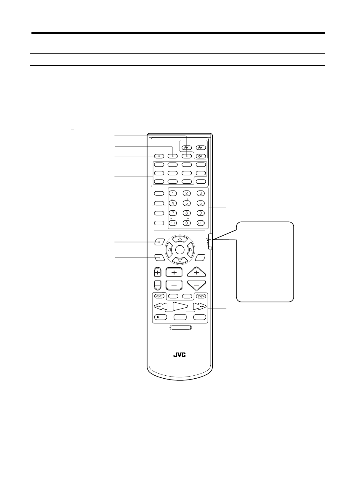
Remote controls
FM/AM
AUX
SUBTITLE
TITLE
DIGEST
ZOOM
CONTROL
POSITION
RDS DISPLAY
SUBWOOFER
VCR
SLEEP
SETTING
PLAY
MODE
THEATER
CENTER
TV
REAR-L
REAR-R
TV RETURN FM MODE
EON SELECT
-
PTY
PTY SEARCH
CHANNELTV VOL VOLUME
TV/VIDEO
/REW
PLAY
TUNING
REC
STOP
DVD MENU
RM-STHA9R
DVD CINEMA SYSTEM
ENTER
EON
STANDBY/ON
DVD
DECODE
TIME
CHOICEANGLERETURN
MUTING
AUDIOTV
VCR
AUDIO
DISPLAY
SOUND
EFFECT
TEST
100+
+PTY
DSP
MODE
F.SEARCHB.SEARCH
FF/
UPDOWN
PAUSE
STROBEMEMORY
DVD
RDS
Parts Identification
Parts Identification
Parts IdentificationParts Identification
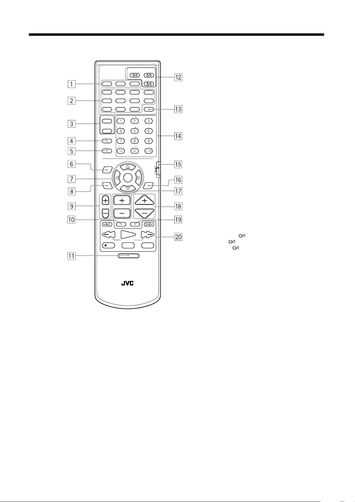
1 Source selecting buttons (14, 18, 41)
AUX, FM/AM, DVD
2 DVD operating buttons
TITLE (25)
SUBTITLE (31)
DECODE (19)
AUDIO (32)
ZOOM (31)
DIGEST (28)
TIME (38, 39)
DISPLAY (37, 38)
RETURN (26)
ANGLE (33)
CHOICE (44)
3 Control buttons VCR/TV (55, 56)
4 SLEEP button (20)
5 SETTING button (50)
6 PLAY MODE button (34, 35, 36, 37)
7 Cursor (EON SELECT, PTY +, PTY
SEARCH, PTY –) and ENTER
(EON) buttons (42, 43)
8 THEATER POSITION (RDS
DISPLAY MODE) button (42)
9 TV VOL +, – button (55)
p TV/VIDEO button (55)
q DVD MENU button (25)
w STANDBY/ON buttons
AUDIO (17, 22)
TV (17, 22, 55, 56)
VCR (56)
e SOUND button (53, 54)
r Number buttons
t Remote control mode selector (55)
DVD, RDS
y DSP MODE button (21)
u CHANNEL +, – button (55, 56)
i VOLUME +, – button (17)
o MUTING button (18)
; Operating buttons (23, 24, 40, 41)
13
13
1313
EnglishEnglishEnglishEnglishEnglishEnglishEnglish
Page 16
■■
Principles of operation
The system may be operated via the remote control or the buttons on the center unit, or via the menu on the screen.
EnglishEnglishEnglishEnglishEnglishEnglishEnglish
Operation with the remote control
Select the appropriate mode for the remote control when the remote control is used for operation.
The remote control mode is selected by pressing the source selecting buttons.
Press DVD:
Press FM/AM:
Press AUX:
Source
selecting
buttons
The DVD operation buttons, number buttons, PLAY MODE button, THEATER POSITION button and operating buttons
operate in DVD mode, enabling operation of the DVD, Audio CD, and Video CD discs.
The number buttons and operating buttons operate in the radio mode. In Radio mode, nothing will be displayed on the TV.
Press to listen to sound inputted to the AUX jacks. In AUX mode, only the VOLUME + and – buttons ar e operable. Also,
nothing will be displayed on the TV.
DVD button
STANDBY/ON
DVD
DECODE
TIME
CHOICEANGLERETURN
AUDIOTV
VCR
AUDIO
DISPLAY
SOUND
EFFECT
TEST
100+
DVD
RDS
+PTY
DSP
MODE
Number buttons
Set to
RDS
RDS with FM
broadcasts.
RDS may be used by
using the cursor and
pressing the ENTER
to use
FM/AM button
AUX button
DVD operating buttons
PLAY MODE
THEATER POSITION
AUX
TITLE
ZOOM
CONTROL
VCR
TV
SLEEP
SETTING
PLAY
MODE
-
PTY
THEATER
POSITION
RDS DISPLAY
FM/AM
SUBTITLE
DIGEST
SUBWOOFER
CENTER
REAR-L
REAR-R
TV RETURN FM MODE
EON SELECT
ENTER
EON
PTY SEARCH
and THEATER
CHANNELTV VOL VOLUME
POSITION button.
Set to
DVD
to use
other than RDS.
MUTING
/REW
REC
TV/VIDEO
PLAY
TUNING
STOP
DVD MENU
F.SEARCHB.SEARCH
FF/
PAUSE
STROBEMEMORY
UPDOWN
Operating buttons
RM-STHA9R
DVD CINEMA SYSTEM
Note:
• The remote control mode is affected by the source selecting buttons as well as the SOUND, VCR, TV buttons, and the remote
control mode selector (DVD-RDS).
See pages 42, 53 and 55 for details.
14
14
1414
Page 17
Principles of operation
Principles of operation
Principles of operationPrinciples of operation
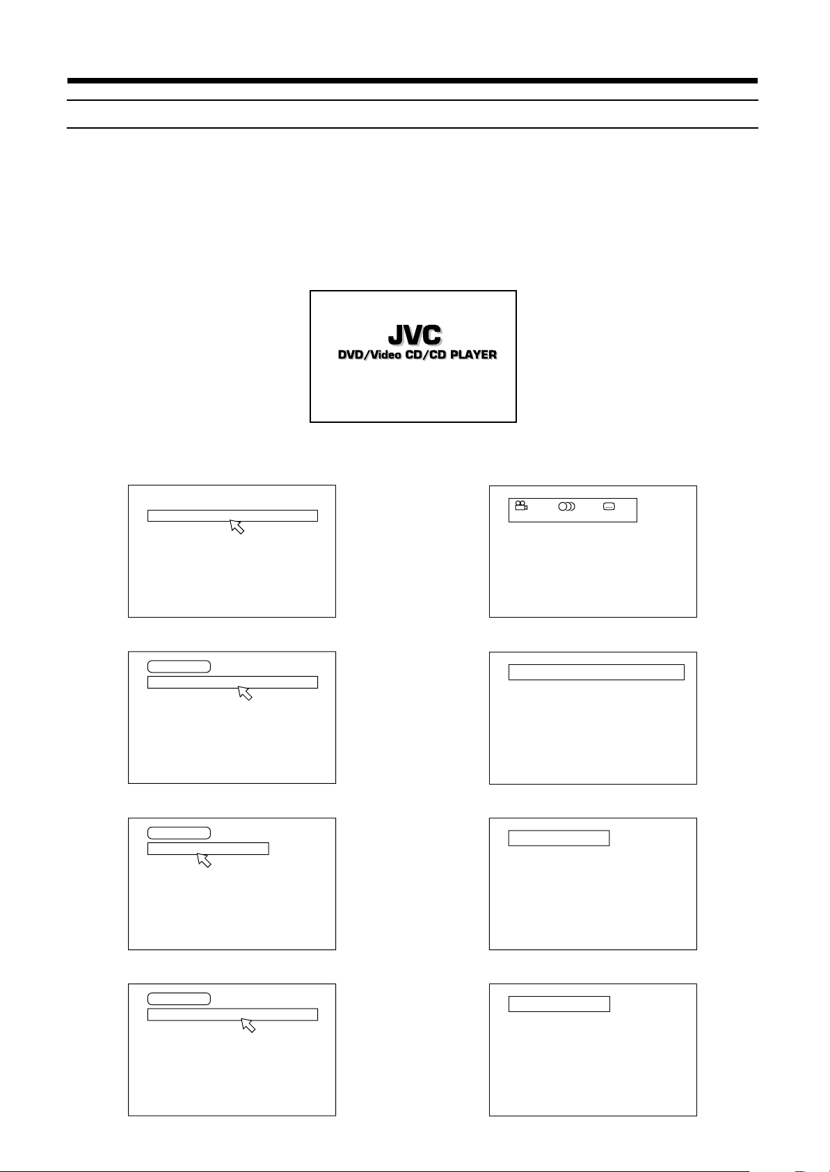
On-screen displays
The center unit provides several on-screen displays.
With some displays, you can set or select preferences or functions, while the others are display-only.
Opening screens
The Opening screen appears automatically in some conditions.
At the bottom, the following information are indicated depending on the center unit’s status.
• NOW READING: The center unit is now reading the disc information (TOC).
• REGION CODE ERROR!: The DVD disc loaded cannot be played because the region code of the disc does not match the center unit.
• OPEN: The disc cover is now opening.
• CLOSE: The disc cover is now closing.
Opening display
NOW READING
Play mode displays
While stopped
REPEAT PROGRAM RANDOM
During DVD playback
DVD CONTROL
REPEAT A-B REPEAT TIME SEARCH CHAP. SEARCH
During Audio CD playback
CD CONTROL
REPEAT A-B REPEAT TIME SEARCH
Status displays
DVD function status
1 / 2 1 / 2 1 / 2
ENGLISH ENGLISH
Disc/time (DVD)
TITLE CHAP. TIME BITRATE
1 25 2:25:25 3.3
Disc/time (Audio CD/Video CD without PBC)
1 0:08
TRACK TIME
EACH
REMAIN
Mbps
During Video CD playback
VCD CONTROL
REPEAT A-B REPEAT TIME SEARCH PBC CALL
Disc/time (Video CD with PBC)
TRACK TIME
1 25:25 PBC
15
15
1515
EnglishEnglishEnglishEnglishEnglishEnglishEnglish
Page 18
Principles of operation
Principles of operation
Principles of operationPrinciples of operation
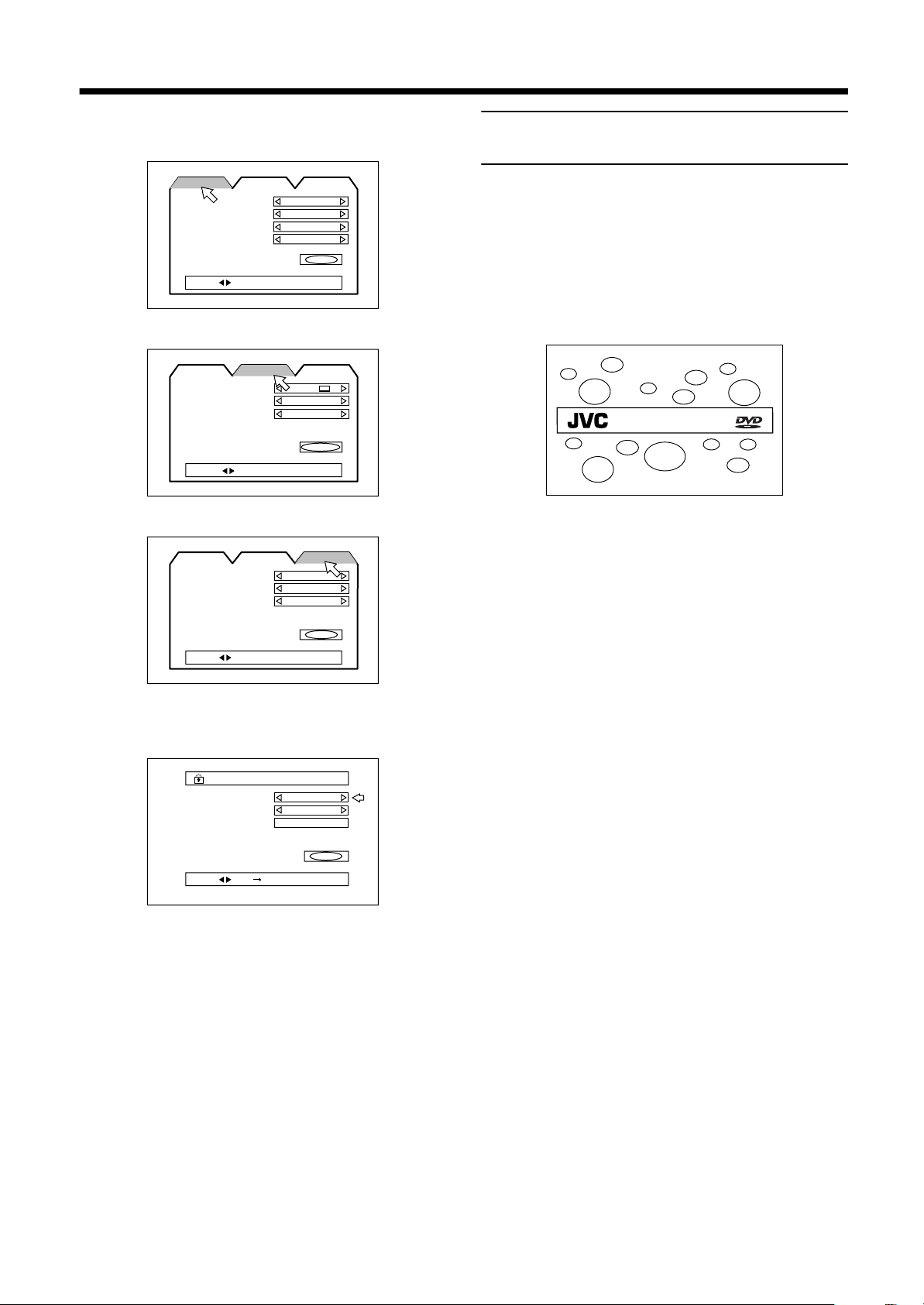
On-screen menus for setting preferences
EnglishEnglishEnglishEnglishEnglishEnglishEnglish
LANGUAGE
LANGUAGE
MENU LANGUAGE
AUDIO LANGUAGE
SUBTITLE
ON SCREEN LANGUAGE
PRESS KEY
DISPLAY
LANGUAGE
MONITOR TYPE
SCREEN SAVER
ON SCREEN GUIDE
PRESS KEY
SYSTEM
LANGUAGE
AUTO STANDBY
RESUME
AV COMPULINK MODE
DISPLAY SYSTEM
ENGLISH
ENGLISH
ENGLISH
ENGLISH
DISPLAY
4:3 LB
MODE 2
ON
DISPLAY
OFF
OFF
DVD 1
EXIT
SYSTEM
EXIT
SYSTEM
Preventing screen burn-out with
the screen saver [SCREEN SAVER]
A television monitor screen may be burned out if a static picture is
displayed for a long time. To prevent this, the center unit
automatically activates the screen saver function if a static picture,
such as an on-screen display or menu, is displayed for over 5
minutes.
• Pressing any button on the center unit or the remote control unit
will release the screen saver function and return to the previous
display.
• You can select one of several screen saver modes available (see
page 46).
DVD/Video CD/CD PLAYER
Note:
• The screen saver does not work during playing back an
Audio CD or while stopped after played back an Audio CD.
EXIT
PRESS KEY
On-screen menus for setting parental lock
PARENTAL LOCK
PARENTAL LOCK
Country Code
Set Level
PASSWORD
PRESS KEY ENTER
GB
—
----
EXIT
On-screen menus for using discs
The disc status and items are displayed as follows on the on-screen
menus for using the disc.
16
16
1616
Page 19
■■
DVD
VCR
DECODE
SUBTITLE
TITLE
AUDIO
TIME
DIGEST
ZOOM
VCR
CONTROL
SUBWOOFER
EFFECT
CENTER
TEST
DISPLAY
CHOICEANGLERETURN
SOUND
FM/AM
AUX
AUDIOTV
STANDBY/ON
TV
TUNING
UPDOWN
REC
/REW
FF/
PAUSE
TV/VIDEO
MUTING
F.SEARCHB.SEARCH
PLAY
CHANNELTV VOL VOLUME
PLAY
MODE
THEATER
POSITION
DSP
MODE
PTY SEARCH
RDS DISPLAY
PTY
-
+PTY
RDS
ENTER
EON
VOLUME + / –
VOLUME + / –
Basic operations
The basic operations for this system are as follows.
IMPORTANT
Check that remote control mode selector is set to “DVD” except
when you use the RDS (Radio Data System) for receiving FM
stations.
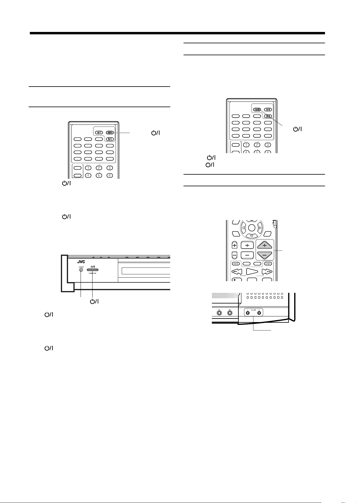
To turn the system power supply
ON and OFF (standby)
From the remote control:
STANDBY/ON
AUDIOTV
AUX
TITLE
ZOOM
CONTROL
VCR
TV
FM/AM
SUBTITLE
DIGEST
SUBWOOFER
CENTER
DVD
DECODE
TIME
CHOICEANGLERETURN
VCR
AUDIO
DISPLAY
SOUND
EFFECT
TEST
Press AUDIO to turn power on.
The STANDBY lamp goes off, and the current source name
(DVD, AM or FM station frequency, or AUX) appears on the
display window. At this time, the disc cover slides backwards and
the top buttons on the center unit appears.
Press AUDIO again to turn power off (standby).
The STANDBY lamp is lit.
The disc cover slides forward to cover the top buttons on the center
unit and the center unit turns off.
On the center unit:
AUDIO
To turn TV power ON and OFF
JVC TVs may be used as is with the remote control. TVs from
other manufacturers require changes to the transmittable signals
before they can be used with the remote control. See page 55 for
details of changing the transmittable signals.
From the remote control:
Press TV to turn power on.
Press TV again to turn power off.
Adjusting volume [VOLUME]
The volume level can be adjusted within the range of “0”
(minimum) to “80” (maximum).
Common:
From the remote control
DVD DIGITAL CINEMA SYSTEM TH-A9R
STANDBY lamp
Press to turn power on.
The STANDBY lamp goes off, and the current source name
(DVD, AM or FM station frequency, or AUX) appears on the
display window. At this time, the disc cover slides backwards and
the top buttons on the center unit appears.
Press again to turn power off (standby).
The STANDBY lamp is lit.
The disc cover slides forward to cover the top buttons on the center
unit and the center unit turns off.
Notes:
• The powered sub-woofer power supply is linked to the
center unit. The green POWER ON lamp on the powered
sub-woofer lights when power is turned on, and goes off
when power is turned off.
• A small amount of power is consumed in the standby
mode (center unit only). Remove the AC power cord from
the AC outlet to turn the center unit off completely.
On the center unit
Press VOLUME + or –.
Press VOLUME + to increase volume.
Press VOLUME – to decrease volume.
CAUTION:
Always set the volume to the minimum before starting
any source.
If the volume is set at its high level, the sudden blast
of sound energy can permanently damage your
hearing and/or ruin your speakers.
EnglishEnglishEnglishEnglishEnglishEnglishEnglish
17
17
1717
Page 20
Basic operations
PTY
PTY
ENTER
Selected source name appears
DVD
VCR
DECODE
SUBTITLE
TITLE
AUDIO
TIME
DIGEST
ZOOM
VCR
TV
SLEEP
SETTING
CONTROL
SUBWOOFER
EFFECT
CENTER
TEST
REAR-R
REAR-L
DISPLAY
CHOICEANGLERETURN
SOUND
FM/AM
AUX
AUDIOTV
STANDBY/ON
Source selecting buttons
SOURCE
Basic operations
Basic operationsBasic operations
Sub-woofer volume control and
EnglishEnglishEnglishEnglishEnglishEnglishEnglish
phase setting
Use the VOLUME knob and PHASE button at the rear of the
powered sub-woofer.
VOLUME knob
Mark
PHASE button
VOLUME
PHASE
REVERSR
NOMAL
SUB WOOFER
CONNECTOR
FROM XV - THA9
MAX
MIN
Volume control
Turn the VOLUME knob.
Adjust to a volume appropriate for balance with the other
speaker(s).
The mark indicates the volume position in normal use.
• Adjust when the volume from the sub-woofer is too high or too
low in relation to the volume from the front speaker.
Phase setting
Play sound through the sub-woofer and adjust the PHASE button
to a position (_ REVERSE or — NORMAL) at which the lowest
frequency is heard best.
Note:
• Phase is closely related to the distance from the listening
position to the front speaker and sub-woofer.
While listening, adjust until the lowest frequency is heard
best.
Muting the sound [MUTING]
Selecting the source to play
From the remote control:
Press one of the source selecting buttons.
DVD
FM/AM
AUX
Notes:
• When you press one of the source selecting buttons on the
remote control, the system automatically turns on.
• The cooling fan in the center unit turns on as long as the
DVD is selected as the playback source. It stops when
other playback source (FM/AM or AUX) is selected.
On the center unit:
Select the DVD player.
Select an FM or AM broadcast.
Each time you press the button, the band
alternates between FM and AM.
Select a component connected to the AUX
jacks.
From the remote control only:
Press MUTING to mute the sound through all speakers
connected.
“MUTING” appears on the display window and volume turns off.
To restore the sound, press MUTING again so that “OFF” appears
on the display.
• Pressing VOLUME +/– also restores the sound.
18
18
1818
THEATER
POSITION
RDS DISPLAY
EON
PTY SEARCH
CHANNELTV VOL VOLUME
TV/VIDEO
MUTING
/REW
PLAY
TUNING
REC
STOP
DVD MENU
+
F.SEARCHB.SEARCH
FF/
PAUSE
STROBEMEMORY
DSP
MODE
UPDOWN
MUTING
Press SOURCE until the source name you want appears on
the display.
The source changes as shown below each time the button is
pressed.
====
DVD
====
AM
====
FM
====
==== (back to the beginning)
AUX
Note:
• When AM or FM is selected, the receiving frequency
appears on the display window. At the same time, the AM
or FM indicator lights up on the display window.
Page 21

Basic operations
Basic operations
Basic operationsBasic operations
Changing the decode mode
[DECODE]
You can change the decode mode for digital audio playback.
From the remote control only:
STANDBY/ON
AUDIOTV
DECODE
TIME
CHOICEANGLERETURN
VCR
AUDIO
DISPLAY
SOUND
EFFECT
TEST
FM/AM
1
2
Press DVD to select DVD as the source.
1
Press DECODE to select the decode mode.
2
AUX DVD
SUBTITLE
TITLE
DIGEST
ZOOM
SUBWOOFER
CONTROL
VCR
CENTER
The display changes as shown below each time the button is
pressed.
====
AUTO/PCM
AUTO/PCM
====
==== (back to the beginning)
DTS
Optimized for all discs playable on this
system. (Default)
DTS
Select this mode when playing a DVD disc
recorded in DTS Surround.
The DTS decoder will be selected as the
internal decoder.
Audio channel display indicator
The audio channel indicator shows the audio channel
configuration for the disc currently playing.
The indicators refer to the speaker channel as follows.
Left front speaker channel
L:
Right front speaker channel
R:
Center speaker channel
C:
Right surround speaker channel
RS:
Left surround speaker channel
LS:
Rear speaker channel (monaural)
S:
Sub-woofer channel
LFE:
The audio channel indicator indicates the type of disc currently
playing as follows.
With Dolby digital 5.1 ch or DTS digital 5.1 ch
surround
When to try changing the decode mode
When the decode mode is set to the default AUTO/PCM setting
and a DVD recorded in Dolby Digital Surround or DTS Digital
Surround is played, the internal decoder will be automatically
selected before audio playback begins. Depending on the disc
recorded in DTS Digital Surround, this may result in a brief loss of
audio after playback starts. This is due to lost audio signals that
were inputted during internal decoder selection.
In these instances, lost audio can be prevented by manually
selecting “DTS” beforehand.
However, please note that when the decode mode is set
to DTS, you will be unable to playback audio from discs
recorded in a mode other than the DTS Digital Surround.
After changing the decode mode and playing back a disc, return
the decode mode to “AUTO/PCM”.
Note:
• Changing the playback source (e.g. AM/FM) will
automatically return the decode mode to “AUTO/PCM”.
When a decode mode which differs from the type
of disc being played is selected
Insert a DVD disc in the center unit to display the type of audio
being played in the Decode mode indicator on the display window.
Audio cannot be played if a decode mode which differs from the
displayed mode is selected.
The selected decode mode flashes to indicate that the selected
decode mode does not allow audio playback.
Example:
Flashes
When DTS is selected as the decode mode for Dolby
digital audio.
With Dolby digital (Lt/Rt*)
With stereo sound (e.g. Audio CD)
* Lt/Rt refers to the downmix output when connected
to a device that uses Dolby Pro Logic.
Note:
• The audio channel indicator does not show the actual
speaker channel that is producing sound.
EnglishEnglishEnglishEnglishEnglishEnglishEnglish
19
19
1919
Page 22

Basic operations
DECODE
SUBTITLE
TITLE
AUDIO
O
Refrections from
behind
Early reflections
Direct sounds
Basic operations
Basic operationsBasic operations
Using the Sleep Timer [SLEEP]
EnglishEnglishEnglishEnglishEnglishEnglishEnglish
Using the Sleep Timer, you can fall asleep to music and know the
system will turn off by itself rather than play all night.
From the remote control:
TIME
DIGEST
ZOOM
SUBWOOFER
CONTROL
VCR
TV
SLEEP
SLEEP
SETTING
TV RETURN FM MODE
PLAY
MODE
-
PTY
EON SELECT
Press SLEEP repeatedly.
The shut-off time changes as follows (in minutes):
====
====
====
====
10
20
30
(Canceled) ==== (back to the beginning)
OFF
60
====
90
When the shut-off time comes
The system turns off automatically.
To check or change the time remaining until
the shut-off time
Press SLEEP once.
The remaining time until the shut-off time appears in minutes.
• To change the shut-off time, press SLEEP repeatedly.
CENTER
REAR-L
REAR-R
ENTER
E
====
CHOICEANGLERETURN
N
120
DISPLAY
SOUND
EFFECT
TEST
100+
DVD
RDS
+PTY
====
150
====
called MPEG2-Audio. (MPEG stands for “Motion Picture Expert
Group” and has been originally developed for compressing video
signals.) To watch the soundtracks of video software bearing the
mark , the center unit can provide you with MPEG
Multichannel decoder.
Note:
• Change the decode mode from “AUTO/PCM” to “DTS”
before playing an Audio CD recorded with DTS Digital
Surround. For details, see page 19.
* Manufactured under license from Dolby
Laboratories. “Dolby”, “Pro Logic”, and the double-D
symbol are trademarks of Dolby Laboratories.
Confidential Unpublished Works. c1992-1998 Dolby
Laboratories, Inc. All rights reserved.
**Manufactured under license from Digital Theater
Systems, Inc. US Pat. No. 5,451,942 and other
world-wide patents issues and pending. “DTS” and
“DTS Digital Surround” are trademarks of Digital
Theater Systems, Inc. c1996 Digital Theater
Systems, Inc. All rights reserved.
DAP modes
The sound heard in a concert hall or club consists of direct sound
and indirect sound — early reflections and reflections from
behind. Direct sounds reach the listener directly without any
reflection. On the other hand, indirect sounds are delayed by the
distances of the ceiling and walls. These direct sounds and indirect
sounds are the most important elements of the acoustic surround
effects. The DAP mode can create these important elements, and
gives you a real “being there” feeling.
To cancel the Sleep Timer
Press SLEEP repeatedly until “SLEEP OFF” appears on the
display window.
• Turning off the power also cancels the Sleep Timer.
Using the DSP Modes [DSP MODE]
The built-in Surround Processor provides two types of the DSP
(Digital Signal Processor) mode — Surround mode and DAP
(Digital Acoustic Processor) mode.
Surround modes
With this system, you can use two types of the Surround mode.
Dolby Surround (Dolby Digital and Dolby Pro
Logic)*
Used to watch the soundtracks of software encoded with Dolby
Digital (bearing the mark ) or with Dolby Surround
(bearing the mark ).
Dolby Digital and Dolby Pro Logic can be selected automatically
according to software played back.
DTS Digital Surround**
DTS Digital Surround is a discrete 5.1 channel digital audio format
available on CD and DVD software.
To watch the soundtracks of video software bearing the mark ,
the system can provide you with DTS Digital Surround decoder.
DTS Digital Surround is automatically selected according to
software played back.
MPEG Multichannel
MPEG Multichannel is another discrete 5.1 channel digital audio
format available on DVD software, and uses encoding method
THEATER:
LIVE CLUB:
Gives the feeling of a large theater.
Gives the feeling of a live music club with
a low ceiling.
DANCE CLUB:
HALL:
Gives a throbbing bass beat.
Gives clear vocal and the feeling of a
concert hall.
PAVILION:
Give the spacious feeling of a pavilion with
a high ceiling.
Notes:
• The DSP modes have no effect on monaural sources.
• The DOLBY DIGITAL indicator lights up when the signals
encoded with Dolby Digital come into the system.
• The PRO LOGIC indicator lights up when the signals
encoded with Dolby Pro Logic decoder built in this system
is activated.
• The dts indicator lights up when the signals encoded with
DTS Digital Surround come into the system.
• The effects can be adjusted when the DAP mode is
selected (see page 54).
20
20
2020
Page 23

Basic operations
Basic operations
Basic operationsBasic operations
To select the DSP mode
From the remote control:
Press DSP MODE.
The currently selected DSP mode appears on the display when the
button is pressed, and changes as follows each time the button is
pressed subsequently.
====
SURROUND ON
DANCE CLUB
(back to the beginning)
• “PRO LOGIC”, rather than “SURROUND ON”, is displayed
when a source other than DVD is selected.
• Select “SURROUND ON” when playing a video with audio
recorded in Dolby Pro Logic, Dolby digital, or DTS digital
surround audio.
Selecting “OFF” loses any surround effect, and stereo playback
takes place.
SETTING
PLAY
MODE
PTY
THEATER
POSITION
RDS DISPLAY
====
HALL
-
====
TV RETURN FM MODE
EON SELECT
PTY SEARCH
CHANNELTV VOL VOLUME
TV/VIDEO
ENTER
EON
MUTING
+PTY
F.SEARCHB.SEARCH
100+
DSP
MODE
THEATER
====
PAVILION
DVD
RDS
====
LIVE CLUB
====
DSP MODE
DSP OFF
====
====
When selecting DAP:
Press DSP MODE.
The currently selected DAP mode appears on the display when the
button is pressed, and changes as follows each time the button is
pressed subsequently.
====
THEATER
====
PAVILION
====
LIVE CLUB
====
DSP OFF
====
DANCE CLUB
====
==== (back to the beginning)
HALL
Notes:
• The DSP mode indicator lights up when DAP mode is
selected.
• The SURROUND indicator lights up when SURROUND
mode is selected.
Notes:
• It is possible to select only “SURROUND ON” and
“SURROUND OFF” when playing a Dolby digital audio or
DTS digital audio DVD.
• The DSP mode indicator lights up when DSP mode other
than SURROUND is selected.
• The SURROUND indicator lights up when SURROUND
mode is selected.
On the center unit:
SURROUND
From the unit, SURROUND ON/OFF and DAP mode can be
selected independently.
When playing a DVD disc with audio recorded in
Dolby surround, Dolby digital, or DTS digital
surround audio:
Press SURROUND.
The current status (e.g. “SURROUND OFF”) appears on the
display when the button is pressed, and changes between
“SURROUND ON” and “SURROUND OFF” each time the
button is pressed subsequently.
• “PRO LOGIC”, rather than “SURROUND ON”, is displayed
when a source other than DVD is selected.
DSP MODE
EnglishEnglishEnglishEnglishEnglishEnglishEnglish
21
21
2121
Page 24

■■
Using the DVD player
and represent disc types.
EnglishEnglishEnglishEnglishEnglishEnglishEnglish
To turn on the system and TV
From the remote control:
2
STANDBY/ON
AUDIOTV
DVD
DECODE
TIME
CHOICEANGLERETURN
VCR
AUDIO
DISPLAY
SOUND
FM/AM
AUX
SUBTITLE
TITLE
DIGEST
ZOOM
Press AUDIO üüüü to turn power on.
1
• Pressing ü
Press TV üüüü to turn TV on.
2
• On the TV, select the TV input source to VIDEO (e.g.
VIDEO 1).
• To turn on the other manufacturer’s TV with TV ü, you
need to change the transmittable signal codes beforehand.
See page 55.
ü on the center unit also turns on power.
üü
1
Press OPEN/CLOSE to close the disc cover.
3
• When the current playback source is DVD, “CLOSE”
appears on the display window. On the TV, “CLOSE”
message appears on the opening on-screen.
• After the disc cover is closed, “READING” appears on the
display window. Then, the disc information is read and, if
the current playback source is DVD, the information is
displayed as described in “Display when a disc is inserted”
on page 23. On the TV, while disc information is reading,
“NOW READING” message appears on the opening onscreen.
Remove the disc after playback has finished.
4
Press OPEN/CLOSE to open the disc cover.
Then, remove the disc as shown below:
After that, press OPEN/CLOSE to close the disc cover.
CAUTION:
Do not put anything on the disc cover since it slides
back and forth, or opens. Doing so may result in
damage to the unit.
Notes:
• When you use Audio CDs, since no screen other than
opening screen is displayed, turning on the TV may not be
required.
• For detailed power on operation including the STANDBY
indicator illumination, see page 17.
To insert a disc
After turning on the system and the TV, insert a disc as follows:
On the center unit:
OPEN/CLOSE
Press OPEN/CLOSE to open the disc cover.
1
• When the current playback source is DVD, “OPEN”
appears on the display window. On the TV, “OPEN”
message appears on the opening on-screen.
Notes:
• The system can play back DVD, Audio CD, Video CD, CDR/CD-RW (audio-formatted) discs only. Do not insert other
disc types.
For details about playable disc types, see page 5.
• When OPEN/CLOSE is pressed to close the disc cover,
playback automatically begins with some discs.
• You can insert a disc while playing other source (FM/AM
or AUX).
• When the disc cover is open, you can directly play the disc
by pressing DVD on the remote control or by selecting
“DVD” with SOURCE on the center unit.
• If the Region Code of the disc does not match your
system, “REGION CODE ERROR!” appears on the
opening on-screen on the TV. This means that you cannot
play the disc.
• When OPEN/CLOSE is pressed in standby mode, the
center unit automatically turns on and the disc cover slides
backwards and opens.
Place a disc.
2
Place a disc with label side up so that it is securely seated.
22
22
2222
Page 25

Using the DVD player
DVD MENU
TUNING
UPDOWN
REC
/REW
FF/
PAUSE
STROBEMEMORY
TV/VIDEO
MUTING
F.SEARCHB.SEARCH
PLAY
CHANNELTV VOL VOLUME
STOP
THEATER
POSITION
DSP
MODE
PTY SEARCH
RDS DISPLAY
PTY
-
+PTY
ENTER
EON
DVD
VCR
DECODE
SUBTITLE
TITLE
AUDIO
TIME
DIGEST
ZOOM
VCR
TV
SLEEP
CONTROL
SUBWOOFER
EFFECT
CENTER
TEST
REAR-L
DISPLAY
CHOICEANGLERETURN
SOUND
FM/AM
AUX
AUDIOTV
STANDBY/ON
DVD
PLAY
STOP
7
3
Using the DVD player
Using the DVD playerUsing the DVD player
Display when a disc is inserted
Opening on-screen:
NOW READING
When a DVD is inserted
Display window:
“READING”
====
“DVD”
Note:
• Playback begins immediately with some DVD discs.
When a Video CD is inserted:
Display window:
“READING”
(total number of tracks and total time display)
====
“VCD 12 48:12”
+
“VCD 1 4:12”
After 4 seconds
To play a disc
From the remote control:
Press PLAY or DVD.
Playback begins from the first track.
On the center unit:
(first track time)
When an Audio CD is inserted
Display window:
“READING”
(total number of tracks and total time display)
====
“CD 12 48:12”
After 4 seconds
+
“CD 1 4:12”
(first track time)
Press 3333.
Playback begins from the first track.
To stop the disc
On the remote control: Press STOP.
On the center unit: Press 7.
Note:
• For DVD, or Video CDs recorded with PBC (playback
control), pressing PLAY or
TV. You may select items from the menu screen thus
displayed and call up the locations to be viewed (see
pages 25 and 26 for details).
may display the menu on the
3
EnglishEnglishEnglishEnglishEnglishEnglishEnglish
23
23
2323
Page 26

Using the DVD player
PTY
PTY
ENTER
DVD MENU
TUNING
UPDOWN
REC
/REW
FF/
PAUSE
STROBEMEMORY
TV/VIDEO
MUTING
F.SEARCHB.SEARCH
PLAY
CHANNELTV VOL VOLUME
STOP
THEATER
POSITION
DSP
MODE
PTY SEARCH
RDS DISPLAY
PTY
-
+PTY
ENTER
EON
1
or
¡
4, ¢
DVD MENU
TUNING
UPDOWN
REC PAUSE
STROBEMEMORY
TV/VIDEO
MUTING
F.SEARCHB.SEARCH
PLAY
STOP
FF/
/REW
RM-STHA9R
4
/REW, FF/
¢
Using the DVD player
Using the DVD playerUsing the DVD player
On-screen guide icons
During DVD playback, you may see icons displayed over the
EnglishEnglishEnglishEnglishEnglishEnglishEnglish
picture. These have the following meanings.
Displayed at the beginning of a scene recorded from
multiple angles (see page 33).
Displayed at the beginning of a scene recorded with
multiple audio languages (see page 32).
Displayed at the beginning of a scene recorded with
multiple subtitle languages (see page 31).
A setting is possible to suppress display of these icons. The setting
is entered in the on-screen menu under “On-screen guide settings”
(see page 46 for details).
About invalid operation icon
When you press a button, if the unit does not accept its operation,
appears on your television screen.
Operations are occasionally unacceptable even if is not
displayed.
Note that some operations may not be accepted. For example,
some discs may not allow fast forward, fast backward or slow
motion playback.
Pausing
Fast forward and backward
❏During playback
From the remote control:
Press ¡¡¡¡ or 1111.
Each time you press the button, the fast forward or backward speed
changes as follows:
2× = 5× = 10× = 20× = 60×
To return to the normal speed
Press PLAY.
On the center unit:
From the remote control:
-
THEATER
POSITION
RDS DISPLAY
CHANNELTV VOL VOLUME
TV/VIDEO
/REW
REC
EON
PTY SEARCH
PLAY
TUNING
STOP
DVD MENU
MUTING
+
F.SEARCHB.SEARCH
FF/
PAUSE
STROBEMEMORY
DSP
MODE
UPDOWN
PAUSE
Press PAUSE.
On the center unit:
8
Press 8888 .
Playback is paused.
When using a DVD or Video CD disc, pressing PAUSE or 8 while
paused moves to the next still picture.
Continuously press ¢¢¢¢ or 4444.
Continuously pressing the button increases the fast forward or
backward speed as follows:
5× = 20×
To return to the normal speed
Release ¢ or 4.
Locating the beginning
Locates the beginning of the title or
chapter with DVDs.
Locates the beginning of the track with Audio CDs and Video
CDs.
❏For DVD: During playback
For Audio CD: During playback or when stopped
For Video CD: During playback or when stopped
From the remote control:
To resume playback
From remote control: Press PLAY.
On the center unit: Press 3.
24
24
2424
Press FF/¢¢¢¢ or 4444/REW.
Page 27

Using the DVD player
TUNING
UPDOWN
REC
/REW
FF/
PAUSE
STROBEMEMORY
TV/VIDEO
MUTING
F.SEARCHB.SEARCH
PLAY
CHANNELTV VOL VOLUME
STOP
PLAY
MODE
THEATER
POSITION
DSP
MODE
DVD MENU
PTY SEARCH
EON SELECT
RDS DISPLAY
PTY
-
+PTY
RDS
DVD
ENTER
EON
DVD
VCR
DECODE
SUBTITLE
AUDIO
TIME
DIGEST
ZOOM
VCR
TV
CONTROL
SUBWOOFER
EFFECT
CENTER
TEST
DISPLAY
CHOICEANGLERETURN
SOUND
FM/AM
AUX
TITLE
AUDIOTV
STANDBY/ON
1
2
1
Using the DVD player
Using the DVD playerUsing the DVD player
On the center unit:
4, ¢
Press ¢¢¢¢ or 4444.
Press 4 to locate the beginning of the current chapter, title, or
track. Press 4 twice quickly to locate the beginning of the
previous one.
Press ¢ to locate the beginning of the next chapter, title, or track.
Note:
• When you play a Video CD with PBC function or a DVD
disc, the center unit may locate different place, but it will
generally locate the beginning of the title or chapter or
track.
Resuming playback
The center unit stores the position on a disc where you want to
interrupt playback at, and resumes playback from that position
later.
To let work the resuming playback, the item RESUME in the
SYSTEM menu must be set to ON beforehand. Otherwise, set it to
OFF. See page 47.
To clear the stored position
To clear the stored position, perform one of the following
operations:
The RESUME indicator on the display window will go out.
• Open the disc cover.
• While stopped, press STOP on the remote control or 7 on the
center unit once again.
• In standby mode, press AUDIO on the remote control or
on the center unit once again to turn on the system.
Selecting playback from the DVD
menu
DVD discs generally have their own menus which show the disc
contents. These menus contain various items such as titles of a
movie, names or songs, or artist information, and display them on
the TV.
You can locate a desired scene by using the menu.
❏During playback
From the remote control only:
To store the playback position
During playback, press STOP or AUDIO on the remote
control.
Or
During playback, press 7777 or on the center unit.
The center unit stores the position at which STOP or 7 is pressed,
and the RESUME indicator on the display window is lit. The last
stored memory overrides the previous memory.
Note:
• The interrupted position is stored even when AUDIO
on the remote control, or on the center unit, is
pressed to switch power OFF (standby).
To resume playback from the stored position
While stopped, press PLAY on the remote control or press
3333 on the center unit.
Playback begins from the stored position.
• When the center unit is in standby mode, you can activate
resuming playback by pressing PLAY on the remote control.
• Changing the source during playback also stores the interrupted
position. To resume playback from the stored position, press
PLAY or DVD on the remote control. Selecting “DVD” by
pressing SOURCE or pressing 3 on the center unit will also
resume playback.
Notes:
• When you perform the resuming operation for a Video CD
• Resuming playback does not work for Audio CDs.
• Resuming playback does not work for program play and
with the PBC function, the center unit may resume
playback from a point slightly earlier than the resume point
you stored.
random play.
1
Press DVD MENU or TITLE.
The menu appears on the TV screen.
Example
2
Press the
2222/3333/5555/∞∞∞∞
cursors to select a
desired item, then press ENTER.
The center unit starts playback of the selected item.
• With some discs, you can also select items by entering the
corresponding number using the number buttons, which
may cause the unit to automatically start playback.
About menu
Normally, a DVD disc which contains more than one title may
have a “title” menu which lists the titles. In this case, the menu
appears on the TV by pressing TITLE . Some DVD discs may also
have a different menu which appears by pressing DVD MENU.
See the instructions of each DVD disc for its particular menu.
Notes:
• When appears on the TV by pressing TITLE in step
1:
The disc does not have a menu listing the titles.
•
When appears on the TV by pressing DVD MENU in
step 1:
The disc does not have a menu.
25
25
2525
EnglishEnglishEnglishEnglishEnglishEnglishEnglish
Page 28

Using the DVD player
1
Using the DVD player
Using the DVD playerUsing the DVD player
Selecting the location to view from
EnglishEnglishEnglishEnglishEnglishEnglishEnglish
the Video CD menu
When playing back Video CDs recorded with PBC (playback
control), a list of the recorded contents may appear on the TV as a
menu. The location to view may be conveniently called up from
this menu screen.
❏When the menu appears on the TV during playback with PBC.
From the remote control only:
TIME
DIGEST
ZOOM
RETURN
Use the number buttons (1~10, +10) to select
1
CONTROL
VCR
TV
SLEEP
SETTING
ANGLERETURN
SUBWOOFER
TV RETURN FM MODE
the desired number of the item.
To select 3 on menu : Press 3.
To select 11 on menu : Press +10 = 1.
Playback starts from the selected item.
Example
Press RETURN to return to the menu screen.
When “NEXT” or “PREVIOUS” appears on the TV, the
center unit generally works as follows:
• Pressing ¢ turns to the next page.
• Pressing 4 returns to the previous page.
The method of the operation is different depending on the
disc.
Activating the PBC function
To activate the PBC function when a PBC-compatible Video
CD is being played back without the PBC function, press
STOP then press PLAY.
When the PBC function is activated, “PBC” appears on the
display window.
You can also activate the PBC function using the on-screen
display as follows:
1. Press PLAY MODE.
2. Press the 2222/3333 cursors to move the pointer to [PBC CALL],
then press ENTER.
During Video CD playback
CENTER
REAR-L
REAR-R
CHOICE
DISPLAY
SOUND
EFFECT
TEST
100+
1
To specify the title, chapter, or
track number for playback
Use the number buttons to specify the title (DVDs) or track
number (CDs) to begin playback from the desired location.
❏For DVD: While stopped (for title playback)
During playing back a screen other than the
menu screen (for chapter playback)
For Audio CD: During playback or while stopped
For Video CD: During playback without PBC function or
while stopped
From the remote control only:
CHOICEANGLERETURN
CENTER
REAR-L
REAR-R
SOUND
EFFECT
TEST
100+
SUBWOOFER
CONTROL
VCR
TV
SLEEP
SETTING
TV RETURN FM MODE
Press the number buttons (1~10, +10) to select
1
the desired title, chapter, or track number.
Selecting numbers
Selecting 1~10:
Press the relevant button between 1 and 10.
Selecting 11 or higher:
To select 13: Press +10 = 3 .
To select 24: Press +10 = +10 = 4.
To select 40: Press +10 = +10 = +10 = 10.
The specified title, chapter, or track number appears on the display
window, and playback begins from that location.
• You can also see the selected title, chapter, or track number on
the on-screen display.
Notes:
• When appears on the TV.
The title, chapter, or track you have selected is not
contained in the disc.
• This function does not work during Video CD playback
with PBC function.
VCD CONTROL
REPEAT A-B REPEAT TIME SEARCH PBC CALL
Cancelling the PBC function
If you want to play back a PBC-compatible Video CD without
activating the PBC function, start playback by using the
number buttons instead of the PLAY button.
26
26
2626
Page 29

Using the DVD player
CHOICEANGLERETURN
SOUND
GO TO CHAPTER =
DVD CONTROL
REPEAT A-B REPEAT TIME SEARCH CHAP. SEARCH
EON SELECT
RDS DISPLAY
PTY
-
+PTY
VCR
TV
SLEEP
SETTING
TV RETURN FM MODE
100+
RDS
DVD
CONTROL
SUBWOOFER
EFFECT
CENTER
TEST
REAR-R
ENTER
EON
THEATER
POSITION
DSP
MODE
REAR-L
PLAY
MODE
1
3
2, 4
Using the DVD player
Using the DVD playerUsing the DVD player
To play from the beginning of a
title, chapter, or track
The beginning of previous or later titles, chapters, or tracks may be
skipped.
❏For DVD: During playback
For Audio CD: During playback or while stopped
For Video CD: During playback without PBC function or
From the remote control only:
Press ¢
1
• Press ¢ the required number of times to move to a later
title, chapter, or track.
• Press 4 the required number of times to return to the
previous title, chapter, or track.
• Press 4 once to return to the beginning of the title,
chapter, or track currently playing.
Notes:
• Press ¢ or 4 on the center unit for the same
operation.
• This function may not work with some DVD discs.
• This function does not work during Video CD playback
with PBC function.
To specify the chapter number for
playback [CHAP. SEARCH]
If the current title of a DVD disc being played is divided into
chapters, you can skip to a desired chapter by specifying the
chapter number using the on-screen display.
❏During playback
From the remote control only:
Press PLAY MODE.
1
The on-screen display appears on the TV.
Press the 2222/3333 cursors to move the pointer to
2
[CHAP. SEARCH], then press ENTER.
¢ or 4
¢¢
1
while stopped
CHANNELTV VOL VOLUME
TV/VIDEO
/REW
PLAY
TUNING
REC PAUSE
STOP
DVD MENU
1
4.
44
SUBWOOFER
CONTROL
VCR
CENTER
TV
REAR-L
SLEEP
REAR-R
SETTING
TV RETURN FM MODE
EON SELECT
PLAY
MODE
ENTER
-
PTY
EON
THEATER
POSITION
RDS DISPLAY
MUTING
F.SEARCHB.SEARCH
FF/
UPDOWN
STROBEMEMORY
EFFECT
TEST
100+
DVD
RDS
+PTY
DSP
MODE
3
2, 4
“GO TO CHAPTER = ” appears under the menu.
Press the number buttons (0 ~ 9) to enter the
3
desired chapter number.
The selected chapter number appears in the message area.
Example:
To select chapter number 8: Press 8.
To select chapter number 37: Press 3 = 7.
Press ENTER.
4
The center unit starts playback from the selected chapter.
To return to the regular display
Press PLAY MODE again.
Notes:
• When the chapter number is incorrect in step 3:
Overwrite the incorrect number with the correct number.
• When is displayed in the TV screen in step 4:
The chapter you have selected is not contained in the disc,
or chapter search does not work on the disc.
• With some discs, the center unit automatically starts
searching for the chapter after entering the chapter
number in step 3.
To specify the time for playback
[TIME SEARCH]
You can play a disc from the desired position by specifying the
elapsed time from the beginning of the disc use the TIME
SEARCH function.
Note that some DVD discs do not contain time information, and
the TIME SEARCH function cannot be used.
❏For DVD: During playback
For Audio CD: During playback
For Video CD: During playback without PBC function
From the remote control only:
Press PLAY MODE.
1
The on-screen display appears on the TV.
Press the 2222/3333 cursors to move the pointer to
2
[TIME SEARCH], then press ENTER.
“GO TO” appears under the menu.
27
27
2727
EnglishEnglishEnglishEnglishEnglishEnglishEnglish
Page 30

Using the DVD player
TUNING
UPDOWN
REC PAUSE
STROBEMEMORY
TV/VIDEO
MUTING
F.SEARCHB.SEARCH
PLAY
CHANNELTV VOL VOLUME
STOP
DVD
DECODE
SUBTITLE
TITLE
AUDIO
TIMEZOOM
VCR
TV
SLEEP
SETTING
TV RETURN FM MODE
100+
CONTROL
SUBWOOFER
EFFECT
CENTER
TEST
REAR-R
PLAY
MODE
THEATER
POSITION
DSP
MODE
REAR-L
DISPLAY
CHOICEANGLERETURN
SOUND
FM/AM
AUX
DVD MENU
/REW
FF/
DIGEST
PTY SEARCH
EON SELECT
RDS DISPLAY
PTY
-
+PTY
RDS
DVD
ENTER
EON
1
2,3
FF/
¢4
/REW
Using the DVD player
Using the DVD playerUsing the DVD player
EnglishEnglishEnglishEnglishEnglishEnglishEnglish
(for DVD)
DVD CONTROL
REPEAT A-B REPEAT TIME SEARCH CHAP. SEARCH
GO TO 2 : 3 4 : 0 0
Selected time
(for Audio CD)
CD CONTROL
REPEAT A-B REPEAT TIME SEARCH
GO TO 0 2 : 3 4
Selected time
(for Video CD)
VCD CONTROL
REPEAT A-B REPEAT TIME SEARCH PBC CALL
GO TO 0 2 : 3 4
3
Use the number buttons (0~9) to enter the
Selected time
time.
The specified time appears in the message area.
Example (for DVD):
To playback from 2(H):34(M):00(S)
To select the screen for playback
from the digest screen [DIGEST]
The unit can display the opening scene of each title or chapter on
a DVD or each track of a Video CD.
You can select a desired title, chapter or track from the opening
scenes displayed on the TV.
❏For DVD: While stopped or during playback
For Video CD: While stopped or during playback without
PBC function.
From the remote control only:
You do not have to press “0” to
enter the trailing zeros (for the
last two digits in the example).
Press “2”
Of course, it is possible to enter
them.
• You can specify the time in
Press “3”
hour/minute/second format
for DVD discs, and in
minute/second format for
Press “4”
Audio and Video CDs.
Press ENTER
When you make a mistake:
Press the 2 cursor to move the cursor to an incorrect number
and enter the correct number.
4
Press ENTER.
The center unit starts playback from the selected time.
To return to the regular display
Press PLAY MODE again.
Notes:
• When appears on the TV in step 2:
The time you have selected is not contained on the disc,
or the TIME SEARCH function does not work on the disc.
• During program play or random play, the TIME SEARCH
function does not work.
1
Press DIGEST.
• DVD is stopped
Up to nine first scenes of
each title may be
displayed.
• DVD is playing
Up to nine first scenes of
each chapter in the
current title may be
displayed.
• Video CD
Up to nine first scenes of
each track may be
displayed.
28
28
2828
Page 31

2
DVD MENU
TUNING
UPDOWN
REC
STROBEMEMORY
TV/VIDEO
MUTING
F.SEARCHB.SEARCH
PLAY
CHANNELTV VOL VOLUME
STOP
FF/
/REW
PAUSE
PTY SEARCH
RDS DISPLAY
2
1
Press the 2222/3333/5555/∞∞∞∞ cursors to select the
desired title, chapter, or track.
When the disc contains more than 9 titles, chapters, or tracks,
the digest screen will have more than one page.
In this case, display a different page of the digest with the
method described below.
To display the next page: Press
To display the previous page: Press
¢¢¢¢
.
4444
.
Or
When the selected title, chapter or track is in the upper lefthand corner of the screen, press the 2 cursor.
When the selected title,
chapter, or track is in
the lower right-hand
corner for the screen,
press the 3 cursor.
3
Press ENTER.
The center unit starts playback from the selected title, chapter
or track.
To return to the regular display before pressing
ENTER in step 3:
Press DIGEST again.
Note:
• With some discs, depending on the contents, it may take
some time until all the scenes appear on the screen.
To advance the picture one frame
at a time
Advancing a paused still picture one frame at a time.
❏During playback
From the remote control:
THEATER
POSITION
RDS DISPLAY
PTY SEARCH
DSP
MODE
Using the DVD player
Using the DVD player
Using the DVD playerUsing the DVD player
Slow-Motion Playback [SLOW]
❏During playback
From the remote control only:
1
Press PAUSE at the section you wish to view
in slow motion.
The image will pause.
2
Press ¡¡¡¡ or 1111.
Pressing ¡ will playback your selection in slow motion,
starting from the paused frame.
Pressing 1 will playback your selection in reverse slow
motion (DVD only).
Each time you press either button during slow-motion, the
playback speed will increase as follows:
Forward:
Reverse:
Pausing slow-motion playback
Press PAUSE to pause slow-motion playback.
Restoring regular playback
Press PLAY to resume normal playback.
Notes:
• Audio is automatically muted during slow-motion
playback.
• Video CDs cannot be played in reverse slow-motion.
1/32 = 1/16 = 1/8 = 1/4 = 1/3 = 1/2
1/16 = 1/12 = 1/8 = 1/4 = 1/3
CHANNELTV VOL VOLUME
TV/VIDEO
MUTING
PLAY
TUNING
STOP
DVD MENU
F.SEARCHB.SEARCH
FF/
PAUSE
STROBEMEMORY
UPDOWN
1,2
/REW
REC
1
Press PAUSE at the location at which the
picture is to be advanced.
The picture is paused.
2
Press PAUSE again.
Each time you press PAUSE, the still picture advances to the
next frame.
Press PLAY to return to normal playback.
Note:
• You can perform the above operation using 8 button on
the center unit.
29
29
2929
EnglishEnglishEnglishEnglishEnglishEnglishEnglish
Page 32

Using the DVD player
Using the DVD player
Using the DVD playerUsing the DVD player
To display Continuous Photos
EnglishEnglishEnglishEnglishEnglishEnglishEnglish
[STROBE]
Nine still pictures may be displayed one after the other.
❏During playback
From the remote control:
CHANNELTV VOL VOLUME
TV/VIDEO
MUTING
F.SEARCHB.SEARCH
PLAY
TUNING
STOP
DVD MENU
FF/
PAUSE
STROBEMEMORY
UPDOWN
/REW
REC
Press PAUSE continuously to display
1
continuous photos.
When the screen appears displaying the nine pictures, release
PAUSE.
The screen plays back the nine pictures in strobe-like action.
1
• Press PAUSE during strobe playback to pause.
• Press PAUSE to display the next nine still pictures.
• Press PLAY to resume strobe playback.
To clear the strobe screen,
press PAUSE continuously until
the normal screen appears.
Notes:
• Audio is not played during strobe playback.
• You can perform the above operation using 8 button on
the center unit.
30
30
3030
Page 33

Using the DVD player
DVD
DECODE
TITLE
AUDIO
TIME
DIGEST
VCR
TV
SLEEP
SETTING
TV RETURN FM MODE
100+
CONTROL
SUBWOOFER
EFFECT
CENTER
TEST
REAR-R
PLAY
MODE
THEATER
POSITION
DSP
MODE
REAR-L
DISPLAY
CHOICEANGLERETURN
SOUND
FM/AM
AUX
SUBTITLE
ZOOM
PTY SEARCH
EON SELECT
RDS DISPLAY
PTY
-
+PTY
RDS
DVD
ENTER
EON
1
2,3
Using the DVD player
Using the DVD playerUsing the DVD player
Zooming a scene [ZOOM]
❏During playback or while paused.
From the remote control only:
TITLE
ZOOM
CONTROL
VCR
TV
SLEEP
SETTING
PLAY
MODE
PTY
THEATER
POSITION
RDS DISPLAY
Press ZOOM.
1
1
2
“ZOOM” appears on the TV.
The unit zooms in to the center part of the scene to produce a
double-sized image.
SUBTITLE
DIGEST
SUBWOOFER
CENTER
REAR-L
REAR-R
TV RETURN FM MODE
EON SELECT
ENTER
EON
PTY SEARCH
DECODE
TIME
CHOICEANGLERETURN
AUDIO
DISPLAY
SOUND
EFFECT
TEST
100+
+PTY
DSP
MODE
DVD
RDS
Changing the Subtitle Language
[SUBTITLE]
Some DVD discs contain subtitles. With such discs, you can
choose which kind of subtitles to display (or turn off subtitles
entirely). At the beginning of subtitled parts, appears on the
TV.
❏During playback
From the remote control only:
Press SUBTITLE.
1
The on-screen display appears on the TV.
ZOOM
Press the 2222/3333/5555/∞∞∞∞ cursors to move the
2
zoomed-in scene.
To pause zoom play
Press PAUSE.
To resume zoom play, press PLAY.
To return to normal playback
Press ZOOM again.
Note:
• During Zoom play, the picture may be garbled or noisy.
Press the 2222/3333 cursors to select the desired
2
subtitle.
Each time you press the 2/3 cursors, the subtitle changes.
Example:
ENGLISH
1/3 ENGLISH
2/3 FRENCH
3/3 SPANISH
–/3 (off)
Press ENTER.
3
The Subtitle selection display disappears on the TV.
Turning subtitles ON/OFF
Press SUBTITLE.
Pressing SUBTITLE toggles subtitle display ON and OFF.
Notes:
• When appears on the TV:
You cannot select the subtitle.
• The selected language may abbreviated on the TV. See
“Appendix A: Table of languages and their abbreviations”
in this manual.
• The Subtitle selection display will automatically disappear
if you do not change the subtitle for 10 seconds.
1 / 3ON
31
31
3131
EnglishEnglishEnglishEnglishEnglishEnglishEnglish
Page 34

Using the DVD player
DVD
VCR
DECODE
TITLE
TIME
DIGEST
VCR
TV
SLEEP
SETTING
TV RETURN FM MODE
100+
CONTROL
SUBWOOFER
EFFECT
CENTER
TEST
REAR-R
PLAY
MODE
THEATER
POSITION
DSP
MODE
REAR-L
DISPLAY
CHOICEANGLERETURN
SOUND
FM/AM
AUX
SUBTITLE
ZOOM
AUDIO
EON SELECT
PTY
-
+PTY
RDS
DVD
ENTER
EON
1
2,3
Using the DVD player
Using the DVD playerUsing the DVD player
Changing the audio language or
EnglishEnglishEnglishEnglishEnglishEnglishEnglish
sound [AUDIO]
Some DVD discs contain multiple audio tracks. With such discs,
you can choose which audio track to listen to during playback.
At the beginning of “multi-audio language” parts, appears on
the TV.
❏During playback
From the remote control only:
FM/AM
AUX
TITLE
SUBTITLE
DIGEST
ZOOM
SUBWOOFER
CONTROL
VCR
CENTER
TV
SLEEP
SETTING
TV RETURN FM MODE
EON SELECT
PLAY
MODE
PTY
-
THEATER
POSITION
Press AUDIO.
1
The on-screen display appears on the TV.
Press AUDIO or the 2222/3333 cursors to select
2
the desired audio language or sound.
Each time you press the button, the audio language or sound
changes.
Example:
REAR-L
REAR-R
ENTER
EON
DVD
DECODE
TIME
CHOICEANGLERETURN
VCR
AUDIO
DISPLAY
SOUND
EFFECT
TEST
100+
+PTY
DSP
MODE
DVD
RDS
1
2,3
Changing the audio channel
[AUDIO]
For in some karaoke Video CDs, one of the audio channels
includes a vocal while the other does not.
With such discs, you can choose to enjoy karaoke without the
vocal or with the vocal by selecting the audio channel to be played
back.
❏During playback
From the remote control only:
Press AUDIO.
1
The on-screen display appears on the TV.
Select the audio channel(s) to be played
2
back using AUDIO or the 2222/3333 cursors.
Each time you press the button, the audio channel changes.
Example:
1 / 3 ENGLISH
Press ENTER.
3
The Audio selection display disappears on the TV.
Notes:
• When appears on the TV:
You cannot select the audio.
• The selected language may abbreviated on the TV. See
“Appendix A: Table of languages and their abbreviations”
in this manual.
• The Audio selection display will automatically disappear if
you do not change the subtitle for 10 seconds.
32
32
3232
STEREO
STEREO
L
R
STEREO:
You hear normal stereo playback.
You hear the L (Left) channel signal played back
L:
from both the left and right speakers.
You hear the R (Right) channel signal played
R:
back from both the left and right speakers.
Press ENTER.
3
The Audio selection display disappears on the TV.
Notes:
• When appears on the TV:
You cannot select the audio.
• The Audio selection display will automatically disappear if
you do not change the subtitle for 10 seconds.
Page 35

Using the DVD player
DECODE
TITLE
AUDIO
SUBTITLE
TIME
DIGEST
VCR
TV
SLEEP
SETTING
TV RETURN FM MODE
100+
CONTROL
SUBWOOFER
EFFECT
CENTER
TEST
REAR-R
PLAY
MODE
THEATER
POSITION
DSP
MODE
REAR-L
DISPLAY
CHOICERETURN
SOUND
ZOOM
ANGLE
PTY SEARCH
EON SELECT
RDS DISPLAY
PTY
-
+PTY
RDS
DVD
ENTER
EON
1
2,3
The selected camera angle
Using the DVD player
Using the DVD playerUsing the DVD player
Viewing from Multiple Angles
[ANGLE]
You can enjoy a variety of scene angles if the DVD disc contains
“multi-angle” parts, where multiple cameras were used to shoot
the same scene from different angles. You can select one of these
viewing angles from the normal screen or on-screen display.
At the beginning of “multi-angle” parts, appears on the TV.
Using the ANGLE button
❏During playback
From the remote control only:
TIME
1
2,3
ZOOM
CONTROL
VCR
TV
SLEEP
SETTING
PLAY
MODE
-
PTY
THEATER
POSITION
RDS DISPLAY
DIGEST
ANGLE
SUBWOOFER
TV RETURN FM MODE
EON SELECT
PTY SEARCH
CENTER
REAR-L
REAR-R
ENTER
EON
DISPLAY
SOUND
CHOICERETURN
EFFECT
TEST
100+
DVD
RDS
+PTY
DSP
MODE
Selecting an angle from the angle list display
❏During playback
From the remote control only:
Hold down ANGLE for more than 1 second.
1
Up to nine camera angles recorded on a disc appear on the TV.
Press ANGLE.
1
The on-screen display appears on the TV.
Press ANGLE or the 2222/3333 cursors to select
2
the desired angle.
Each time you press the button, the angle changes.
Example:
1 / 3
2 / 3
3 / 3
Press ENTER.
3
The Angle selection display disappears on the TV.
Note:
• When appears on the TV:
The current scene is not recorded from multiple angles.
• The Angle selection display will automatically disappear if
you do not change the subtitle for 10 seconds.
1 / 3
Press the 2222/3333/5555/∞∞∞∞ cursors to select the
2
desired angle.
Press ENTER.
3
The selected angle appears on the TV.
Note:
• When appears on the TV:
The current scene is not recorded from multiple angles.
• During the operation above, audio is muted.
EnglishEnglishEnglishEnglishEnglishEnglishEnglish
33
33
3333
Page 36

Using the DVD player
THEATER 1
THEATER 2
THEATER 3
THEATER OFF
SETTING
TV RETURN FM MODE
100+
THEATER
POSITION
DSP
MODE
PLAY
MODE
PTY SEARCH
EON SELECT
RDS DISPLAY
PTY
-
+PTY
RDS
DVD
ENTER
EON
2
1
REPEAT TITLE
DVD CONTROL
REPEAT A-B REPEAT TIME SEARCH CHAP. SEARCH
REPEAT TITLE (current title repeat)
REPEAT CHAPTER (current chapter repeat)
No indication (off)
The selected repeat
mode appears on the
TV.
REPEAT ALL
CD CONTROL
REPEAT A-B REPEAT TIME SEARCH
Selected repeat mode
REPEAT ALL
VCD CONTROL
REPEAT A-B REPEAT TIME SEARCH PBC CALL
Selected repeat mode
Using the DVD player
Using the DVD playerUsing the DVD player
Selecting the Picture Character
EnglishEnglishEnglishEnglishEnglishEnglishEnglish
[THEATER POSITION]
You can select the quality of the image from among four options
(OFF, 1, 2, and 3) according to the type of programming, picture
tone or personal preferences.
❏During playback
From the remote control only:
1
Press THEATER POSITION to select the
1
desired picture character.
Each time you press the button, the picture character changes
as follows:
SETTING
PLAY
MODE
-
PTY
THEATER
POSITION
RDS DISPLAY
TV RETURN FM MODE
EON SELECT
ENTER
EON
PTY SEARCH
THEATER 1
+PTY
100+
DSP
MODE
DVD
RDS
Repeating a current title, chapter
or track, or all tracks [REPEAT]
❏For DVD: During playback
For Audio CD: During playback or while stopped
For Video CD: During playback without PBC function or while
stopped
From the remote control only:
Press PLAY MODE.
1
The on-screen display appears on the TV.
Press the 2222/3333 cursors to move the pointer to
2
[REPEAT], then press ENTER.
Each time you press ENTER, the repeat mode changes as
follows:
For DVD
“THEATER OFF” is the normal position.
Selecting a higher number results in a darker picture
character.
To turn off the on-screen display
Press ENTER.
• The THEATER POSITION screen will automatically close if
left idle for more than 5 seconds.
34
34
3434
Selected picture character
The current title or chapter will be repeated.
For Audio CD and Video CD
(for Audio CD)
(for Video CD)
REPEAT ALL (all track repeat)
REPEAT 1 (current track repeat)
No indication
(off)
The current track or all tracks is/are played repeatedly.
Page 37

Using the DVD player
CD CONTROL
REPEAT A-B REPEAT TIME SEARCH
A 0:0:16 B 0:1:31
Point A Point B
VCD CONTROL
REPEAT A-B REPEAT TIME SEARCH PBC CALL
A 0:0:16 B 0:1:31
Point A Point B
Using the DVD player
Using the DVD playerUsing the DVD player
To stop repeat playback
Press STOP.
• When a DVD disc is set, the center unit stops playback and
quits repeat mode.
• When an Audio or Video CD is set, the center unit stops
playback but remains in repeat mode.
To quit repeat playback without stopping playback
Move the pointer to [REPEAT] and press ENTER repeatedly until
the [REPEAT] display turns off.
Tu turn off the on-screen display
Press PLAY MODE.
Notes:
• If appears when pressing ENTER in step 2 during
DVD playback.
You cannot repeat the title or chapter because of the disc
contents.
• With some DVD discs, repeat function does not work.
• Repeat play function cannot be used during Video CD
playback with PBC function.
Repeating a desired part [A-B
REPEAT]
❏During playback
From the remote control only:
1
1
Press PLAY MODE.
The on-screen display appears on the TV.
2
Press the 2222/3333 cursors to move the pointer to
[A-B REPEAT], then press ENTER at the
beginning of the part you want to repeat
(point A).
SETTING
PLAY
MODE
-
PTY
THEATER
POSITION
RDS DISPLAY
TV RETURN FM MODE
EON SELECT
ENTER
EON
PTY SEARCH
+PTY
100+
DSP
MODE
DVD
RDS
2,3
(for Audio CD)
(for Video CD)
To quit A-B repeat playback
Press STOP. The center unit stops playback and quits A-B repeat
mode.
Quitting A-B repeat mode without stopping
playback
Move the pointer to [A-B REPEAT] and press ENTER.
Pressing the 4 or ¢ will also quit A-B repeat mode.
To turn off the on-screen display
Press PLAY MODE.
Notes:
• If appears when pressing ENTER in step 2 during
DVD playback.
You cannot repeat the selected portion because of the
disc contents.
• The A-B REPEAT function cannot be used during program
or random playback.
• With DVD discs, A-B repeat playback is possible only
within a single title.
3
Press ENTER at the end of the part you want
to repeat (point B).
The unit locates “A” and starts repeat playback between “A”
and “B”.
(for DVD)
DVD CONTROL
REPEAT A-B REPEAT TIME SEARCH CHAP. SEARCH
A 0:00:16 B 0:01:16
Point A Point B
35
35
3535
EnglishEnglishEnglishEnglishEnglishEnglishEnglish
Page 38

Using the DVD player
CHOICEANGLERETURN
SOUND
REPEAT PROGRAM RANDOM
Using the DVD player
Using the DVD playerUsing the DVD player
Programming the Playing Order
EnglishEnglishEnglishEnglishEnglishEnglishEnglish
[PROGRAM]
You can play titles or tracks on a disc in the desired order using the
Program function.
❏While stopped
From the remote control only:
SUBWOOFER
CENTER
REAR-L
REAR-R
ENTER
EON
PLAY
TUNING
STOP
3
9
15
3
9
15
MUTING
10
16
10
16
EFFECT
TEST
100+
DVD
RDS
+PTY
DSP
MODE
F.SEARCHB.SEARCH
FF/
UPDOWN
PAUSE
STROBEMEMORY
6
5
4
12
11
18
17
6
5
4
12
11
18
17
CONTROL
VCR
TV
SLEEP
SETTING
TV RETURN FM MODE
EON SELECT
PLAY
1
Press PLAY MODE.
1
MODE
-
PTY
THEATER
POSITION
RDS DISPLAY
CHANNELTV VOL VOLUME
TV/VIDEO
/REW
REC
PTY SEARCH
The on-screen display appears on the TV.
Press the 2222/3333 cursors to move the pointer to
2
[PROGRAM] and press ENTER.
REPEAT PROGRAM RANDOM
2
1
3
8
7
14
13
The program table appears under the menu bar (as shown
above).
The PROGRAM indicator appears on the display window.
Select the titles or tracks in the desired order
3
using the number buttons (1~10, +10).
Up to 18 titles or tracks can be programmed. You may select
the same titles or track more than once.
2
1
3
8
7
14
13
3
2
4
Selecting numbers
Selecting 1~10:
Press the relevant button between 1 and 10.
Selecting 11 or higher:
To select 13: Press +10 = 3 .
To select 24: Press +10 = +10 = 4.
To select 40: Press +10 = + 10 = +10 = 10.
If you mistakenly select the wrong title or track number press
STOP to delete the entered program.
Then re-select the titles or tracks you wish.
Press PLAY to start program play.
4
When all of the programmed titles or tracks have finished
playback, the center unit stops. Since the program remains,
program playback can be used again.
• You can use repeat playback together with program
playback for DVDs, Audio CDs and Video CDs. Select
REPEAT ALL to repeatedly play back the all programmed
tracks. For details, see page 34.
To turn off the on-screen display
Press PLAY MODE.
To quit program playback and clear the program
Press STOP and then PLAY MODE to display the on-screen on
the TV. Then, press STOP once again. Now, the program is
cleared. Then, press ENTER.
The PROGRAM indicator on the display window goes off.
Turning off the power, switching source, or opening the disc cover
will also clear the program.
To temporarily exit program playback and clear
the program
There are two ways to do this operation:
• While stopped and the on-screen play mode menu is not
displayed on TV, press STOP.
• While stopped, press PLAY MODE to display the on-screen on
the TV. Then, move the pointer to [PROGRAM] and press
ENTER to exit the program playback. Since the program
remains, program playback can be used again.
Notes:
• With some DVD discs, program playback does not work.
• During program playback, you can skip to the next title or
track by pressing
beginning of the current title or track by pressing
cannot skip back to the previous title or track.)
• During program playback, you can see the current title or
track by pressing the PLAY MODE. The current title or
track illuminates in yellow on the on-screen display. (To
turn off the on-screen display, press PLAY MODE again.)
. Also, you can skip back to the
¢
4
. (You
36
36
3636
The programmed title/track number is shown
under each program number.
Page 39

Using the DVD player
SETTING
DVD
VCR
DECODE
SUBTITLE
TITLE
AUDIO
TIME
DIGEST
ZOOM
CONTROL
SUBWOOFER
EFFECT
DISPLAY
CHOICEANGLERETURN
SOUND
FM/AM
AUX
AUDIOTV
STANDBY/ON
1
ENGLISH ENGLISH
1 / 2 1 / 2 1 / 2
Using the DVD player
Using the DVD playerUsing the DVD player
Random Play [RANDOM]
You can play titles or tracks in random order.
❏While stopped
From the remote control only:
1
Press PLAY MODE.
1
The on-screen display appears on the TV.
Press the 2222/3333 cursors to move the pointer to
2
[RANDOM] and press ENTER.
“RANDOM” appears on the display window, and random
playback begins.
TV RETURN FM MODE
EON SELECT
PLAY
MODE
-
PTY
THEATER
POSITION
RDS DISPLAY
PTY SEARCH
CHANNELTV VOL VOLUME
REPEAT PROGRAM RANDOM
ENTER
EON
+PTY
100+
DSP
MODE
DVD
RDS
2
To check the DVD function status
You can check the DVD function status of the DVD disc.
❏During DVD playback
From the remote control only:
Press DISPLAY once.
1
The on-screen display appears on the TV, and the current
selections of the camera angle, audio language and subtitle
language are displayed.
• When all tracks have been played once, random play ends.
• You can use repeat playback together with random
playback. Select REPEAT ALL to repeatedly play back
the all tracks on the disc. For details, see page 34.
To quit random playback
Press STOP.
Note:
• The same track will not be played back more than once
during random play.
To turn off the DVD function status display
Press DISPLAY twice.
EnglishEnglishEnglishEnglishEnglishEnglishEnglish
37
37
3737
Page 40

Using the DVD player
DVD
VCR
DECODE
SUBTITLE
TITLE
AUDIO
TIME
DIGEST
ZOOM
VCR
CONTROL
SUBWOOFER
EFFECT
CENTER
TEST
DISPLAY
CHOICEANGLERETURN
SOUND
FM/AM
AUX
AUDIOTV
STANDBY/ON
1
2
(
)
Using the DVD player
Using the DVD playerUsing the DVD player
To check the disc information
EnglishEnglishEnglishEnglishEnglishEnglishEnglish
You can check the disc information of the disc.
❏During playback
From the remote control only:
STANDBY/ON
AUDIOTV
DVD
DECODE
TIME
CHOICEANGLERETURN
Time
VCR
AUDIO
DISPLAY
SOUND
EFFECT
FM/AM
AUX
SUBTITLE
TITLE
DIGEST
ZOOM
SUBWOOFER
CONTROL
VCR
Press DISPLAY once for a Audio CD or Video
1
CD, or twice for a DVD disc.
The disc information display appears on the TV.
(for DVD)
TITLE CHAP. TIME BITRATE
1 25 2:25:25 3.3
Current chapter number
Current title number
1
Mbps
Transmission rate
To check the time information
You can check the time information of the disc.
❏For Audio CD: During playback
For Video CD: During playback without PBC function.
From the remote control only:
Press DISPLAY once.
1
The time information display appears on the TV.
Press TIME.
2
Each time you press the button, the time indication changes as
follows:
For Audio CD
EACH
(current track elapsed time)
EACH REMAIN
(current track remaining time)
(for Audio CD or Video CD playing without PBC)
1 0:08
TRACK TIME
EACH
Time mode
Time
Current track number
(for Video CD playing with PBC)
TRACK TIME
1 25:25 PBC
PBC on status
Time
Current track number
To turn off the on-screen display
Press DISPLAY again.
Note:
• With DVD discs, you can directly enter the disc information
on-screen by pressing TIME during playback.
TOTAL
(disc elapsed time)
TOTAL REMAIN
disc remaining time
For Video CD playing without PBC
EACH
(current track elapsed time)
EACH REMAIN
(current track remaining time)
The selected time information is displayed on the TV, as well
as on the display window.
To turn off the on-screen display
Press DISPLAY again.
38
38
3838
Page 41

To check time on the display window
You can check the time information on the display window, rather
than using the on-screen menu.
❏During playback or while stopped
From the remote control only:
STANDBY/ON
AUDIOTV
DVD
DECODE
TIME
CHOICEANGLERETURN
VCR
AUDIO
DISPLAY
SOUND
EFFECT
1
FM/AM
AUX
SUBTITLE
TITLE
DIGEST
ZOOM
SUBWOOFER
CONTROL
VCR
1
Press TIME repeatedly.
Each time you press the button, the time indication changes as
follows:
= EACH = EACH REMAIN = No indication (TOTAL) =
REMAIN = (back to the beginning)
The time indicator (REMAIN/EACH) lights up on the display
window.
During playback
REMAIN: Disc remaining time
TOTAL: Disc elapsed time
EACH: Current track elapsed time
EACH REMAIN: Current track remaining time
While stopped
REMAIN: Total playback time of the disc
EACH/TOTAL: 0:00
EACH REMAIN: Playback time of the current track
By pressing ¢ or 4, playback time for
other tracks can be check.
Using the DVD player
Using the DVD player
Using the DVD playerUsing the DVD player
39
39
3939
EnglishEnglishEnglishEnglishEnglishEnglishEnglish
Page 42

■■
TUNING
UPDOWN
PAUSE
STROBEMEMORY
TV/VIDEO
MUTING
F.SEARCHB.SEARCH
PTY SEARCH
EON SELECT
RDS DISPLAY
PTY
-
+PTY
PLAY
CHANNELTV VOL VOLUME
STOP
DVD
AUDIOTV
STANDBY/ON
VCR
DECODE
SUBTITLE
TITLE
AUDIO
TIME
DIGEST
ZOOM
VCR
TV
SLEEP
SETTING
TV RETURN FM MODE
100+
RDS
DVD
CONTROL
SUBWOOFER
EFFECT
CENTER
TEST
REAR-R
ENTER
EON
PLAY
MODE
THEATER
POSITION
DSP
MODE
REAR-L
DISPLAY
CHOICEANGLERETURN
SOUND
AUX
FM/AM
REC
/REW
FF/
1
3
2,4
1
Receiving radio broadcasts
You can browse through all the stations or use the preset function to go immediately to a particular station.
EnglishEnglishEnglishEnglishEnglishEnglishEnglish
Tuning in stations manually
Using preset tuning
From the remote control only:
STANDBY/ON
AUDIOTV
VCR
1
Press FM/AM to select the band.
1
AUX
TITLE
ZOOM
CONTROL
VCR
TV
SLEEP
SETTING
PLAY
MODE
PTY
THEATER
POSITION
RDS DISPLAY
/REW
REC
DVD
FM/AM
DECODE
SUBTITLE
TIME
DIGEST
CHOICEANGLERETURN
SUBWOOFER
CENTER
REAR-L
REAR-R
TV RETURN FM MODE
EON SELECT
ENTER
EON
PTY SEARCH
CHANNELTV VOL VOLUME
TV/VIDEO
MUTING
PLAY
TUNING
STOP
AUDIO
DISPLAY
SOUND
EFFECT
TEST
100+
+PTY
DSP
MODE
F.SEARCHB.SEARCH
FF/
UPDOWN
PAUSE
DVD
RDS
2
Each time you press the button, the band alternates between
FM and AM.
Once a station is assigned to a channel number, the station can be
quickly tuned. You can preset up to 30 FM and 15 AM stations.
To store the preset stations
Before you start, remember...
• There is a time limit in doing the following steps. If the setting
is canceled before you finish, start from step 1 again.
From the remote control only:
Press TUNING UP (FF/¢
2
DOWN (4
4/REW) repeatedly until you find
44
¢) or TUNING
¢¢
the frequency you want.
• When you hold down the button, the frequency keeps
changing. When you releases the button, tuning
automatically stops at the next station of sufficient signal
strength.
You can use the sound effect, if you want. See “Using the
DSP Modes [DSP MODE]” on page 20.
Note:
• When a station of sufficient signal strength is tuned in, the
TUNED indicator lights up on the display window.
• When an FM stereo program is received, the STEREO
indicator also lights up.
• On the unit, FM and AM can be selected by repeatedly
pressing SOURCE. The frequency last tuned appears on
the display window, but you cannot tune in to the other
station using
or 4 on the center unit.
¢
Tune in the station you want to preset (see
1
“Tuning in stations manually”).
If you want to store the FM reception mode for this stations,
select the FM reception mode you want. See “Selecting the
FM reception mode” on page 41.
Press MEMORY (¶¶¶¶ REC).
2
“CH - -” flashes and the channel number position starts
flashing on the display window for about 10 seconds.
Use the number buttons (1~10, +10) to select a
3
channel number while the channel number
position is flashing.
• For channel number 5, press 5.
• For channel number 15, press +10 = 5.
• For channel number 20, press +10 = 10.
• For channel number 30, press +10 = +10 = 10.
40
40
4040
Page 43

4
VCR
TV
SLEEP
SETTING
TV RETURN FM MODE
100+
CONTROL
SUBWOOFER
EFFECT
CENTER
TEST
REAR-R
PLAY
REAR-L
EON SELECT
DVD
1
DVD
AUDIOTV
STANDBY/ON
VCR
DECODE
SUBTITLE
TITLE
AUDIO
TIME
DIGEST
ZOOM
VCR
TV
SLEEP
SETTING
TV RETURN FM MODE
100+
CONTROL
SUBWOOFER
EFFECT
CENTER
TEST
REAR-R
REAR-L
DISPLAY
CHOICEANGLERETURN
SOUND
AUX
FM/AM
1
Press MEMORY (¶¶¶¶ REC) again while the
selected channel number is flashing.
The selected channel number stops flashing.
The station is assigned to the selected channel number.
5
Repeat steps 1 to 4 until you store all the
stations you want.
To erase a stored preset station
Storing a new station on a used number erases the previously
stored one.
Note:
• The preset stations will be erased in a few days, if the
system is unplugged or power failure occurs.
To tune in a preset station
From the remote control only:
STANDBY/ON
AUDIOTV
VCR
1
1
Press FM/AM.
AUX
TITLE
ZOOM
CONTROL
VCR
TV
SLEEP
SETTING
Each time you press the button, the band alternates between
FM and AM.
2
Press the number buttons (1~10, +10) to select
DVD
FM/AM
DECODE
SUBTITLE
TIME
DIGEST
CHOICEANGLERETURN
SUBWOOFER
CENTER
REAR-L
REAR-R
TV RETURN FM MODE
EON SELECT
AUDIO
DISPLAY
SOUND
EFFECT
TEST
2
100+
a preset channel number.
• For channel number 5, press 5.
• For channel number 15, press +10 = 5.
• For channel number 20, press +10 = 10.
• For channel number 30, press +10 = +10 = 10.
Receiving radio broadcasts
Receiving radio broadcasts
Receiving radio broadcastsReceiving radio broadcasts
Selecting the FM reception mode
When an FM stereo broadcast is hard to receive or noisy
You can change the FM reception mode while receiving an FM
broadcast.
• You can store the FM reception mode for each preset station.
From the remote control only:
1
Press FM MODE.
Each time you press the button, the FM reception mode
alternates between “AUTO” and “MONO.”
AUTO:
“AUTO MUTING” appears on the display
window and the AUTO MUTING indicator lights
up on the display window.
When a program is broadcasted in stereo, you will
hear stereo sound; when in monaural, you will hear
monaural sounds. This mode is also useful to
suppress static noise between stations.
MONO:
“MONO” appears on the display window and the
AUTO MUTING indicator goes off on the display
window.
Reception will be improved although you will lose
the stereo effect. In this mode, you will hear noise
while tuning into the stations.
Beat cut
When listening to an AM broadcast with a lot of noise interference,
you can change the BEAT CUT mode to reduce the noise.
From the remote control only:
1
Press FM MODE.
Each time you press the button, operation toggles between
“BEAT CUT 1” and “BEAT CUT 2” on the display window.
Choose the setting that gives clearer sound.
41
41
4141
EnglishEnglishEnglishEnglishEnglishEnglishEnglish
Page 44

Receiving radio broadcasts
EON SELECT
CHANNELTV VOL VOLUME
VCR
TV
SLEEP
SETTING
TV RETURN FM MODE
100+
CENTER
TEST
REAR-R
PLAY
MODE
THEATER
POSITION
DSP
MODE
REAR-L
PTY SEARCH
EON SELECT
RDS DISPLAY
PTY
-
+PTY
RDS
DVD
ENTER
EON
2
2
1,3
RDS
selected
Receiving radio broadcasts
Receiving radio broadcastsReceiving radio broadcasts
Using the RDS (Radio Data System)
EnglishEnglishEnglishEnglishEnglishEnglishEnglish
to receive FM stations
RDS allows FM stations to send an additional signal along with
their regular program signals. For example, the stations send their
station names, as well as information about what type of program
they broadcast, such as sports or music, etc.
When tuned to an FM station which provides the RDS service, the
RDS indicator lights up on the display window.
With the center unit, you can receive the following types of RDS
signals.
PS (Program Service):
Shows commonly known
station names.
PTY (Program Type):
Shows types of broadcast
programs.
RT (Radio Text):
Shows text messages the
station sends.
EON (Enhanced Other Network):
See page 43.
Notes:
• RDS is not available for AM (MW) broadcasts.
• RDS may not operate correctly if the station tuned is not
transmitting RDS signal properly or if the signal strength is
weak.
IMPORTANT
Set the remote cotnrol mode selector to RDS before using RDS.
What information can RDS signals
provide?
You can see the RDS signals the station sends on the display.
From the remote control only:
DVD
RDS
+PTY
EON
DSP
MODE
RDS
selected
RDS
DISPLAY
MODE
(THEATER
POSITION)
PLAY
MODE
-
PTY
THEATER
POSITION
RDS DISPLAY
CHANNELTV VOL VOLUME
ENTER
PTY SEARCH
About characters shown in the display
window
When the display shows PS, PTY, or RT signals, the following
characters are used.
• The display window cannot differentiate upper case and lower
case letters and always uses upper case letters.
• The display window cannot show accented letters, “A,” for
instance, may stand for accented “A’s” like “Å, Ä, Ã, Á, À, and
Â.”
Note:
• If searching finishes at once, “PS”, “PTY”, and “RT” will not
appear on the display window.
Searching for a program by PTY
codes
One of the advantages of the RDS service is that you can locate a
particular kind of program from the preset channels (see page 40)
by specifying the PTY codes.
To search for a program using the PTY codes
Before you start, remember...
• The PTY Search is only applicable to preset stations.
• To stop searching any time during the process, press PTY
SEARCH while searching.
• There is a time limit in doing the following steps. If the setting
is cancelled before you finish, start from step 1 again.
• When pressing the buttons on the primary remote control, make
sure that you have selected the FM station using the primary
remote control.
From the remote control only:
TV/VIDEO
MUTING
To show the RDS signals
Press RDS DISPLAY MODE (THEATER POSITION) while
listening to an FM station.
• Each time you press the button, the display change to show you
the following information:
= PS = PTY = RT = Frequency = (back to the beginning)
PS (Program Service):
PTY (Program Type):
RT (Radio Text):
Frequency:
42
42
4242
While searching, “PS” appears and
then the station names will be
displayed. “NO PS” appears if no
signal is sent.
While searching, “PTY” appears and
then the type of the broadcast program
will be displayed. “NO PTY” appears if
no signal is sent.
While searching, “RT” appears and
then text messages the station sends
will be displayed. “NO RT” appears if
no signal is sent.
Station frequency (non-RDS service)
1
Press PTY SEARCH while listening to an FM
station.
“PTY SELECT” flashes on the display window.
2
Press and hold PTY – or PTY + until the PTY
code you want appears on the display
window, while “PTY SELECT” is flashing.
The display gives you the PTY codes described to the right.
3
Press PTY SEARCH again, while the PTY
code selected in the previous step is still on
the display window.
While searching, “SEARCH” and the selected PTY code
alternate on the display window.
The center unit searches 30 preset FM stations, stops when it
finds the one you have selected, and tunes in that station.
To continue searching after the first stop
Press PTY SEARCH again while the indications on the display
window are flashing.
If no program is found, “NOT FOUND” appears on the display
window.
Page 45

PTY codes
Receiving radio broadcasts
Receiving radio broadcasts
Receiving radio broadcastsReceiving radio broadcasts
Press EON SELECT until the program type you
2
want appears on the display window.
!
• Each time you press the button, the display changes to
show the following:
=
TA = NEWS = INFO = TA/NEWS = TA/INFO =
=
NEWS/INFO
TA/NEWS/INFO = (back to the beginning)
Switching to a broadcast program
of your choice temporarily
Another convenient RDS service is called “EON (Enhanced Other
Network)”.
The EON indicator lights up while receiving a station with the
EON code.
This allows the center unit to switch temporarily to a broadcast
program of your choice (NEWS, TA, and/or INFO) from a
different station except in the following cases:
• When you are listening to non-RDS stations (all AM (MW) and
some FM stations).
• When listening to sources other than FM broadcasts.
• When the center unit is in standby mode.
Before you start, remember...
• The EON function is only applicable to preset stations.
From remote control only:
Press EON (ENTER) so that the last selected
1
program type appears on the display window.
The center unit enters EON standby mode. When the center
unit is in EON standby mode, the center unit is ready to
receive the EON data (TA/NEWS/INFO) you select.
SLEEP
SETTING
TV RETURN FM MODE
PLAY
MODE
-
PTY
THEATER
POSITION
RDS DISPLAY
CHANNELTV VOL VOLUME
REAR-R
EON SELECT
ENTER
EON
PTY SEARCH
+PTY
100+
DSP
MODE
DVD
RDS
2
RDS
selected
1
TA:
NEWS:
INFO:
Traffic Announcement in your area.
News.
Program the purpose of which is to import advice
on the widest sense.
CASE 1:
When the program you have selected is broadcast
on another station while FM is selected.
«
When a station starts broadcasting the program you
have selected, the center unit automatical ly
switches to the station. The indicator for the
received program type starts flashing.
«
When the program is over, the center unit returns
to the previously selected station, but still remains
in the EON standby mode. The indicator for the
received program type stops flashing an remains
lit.
CASE 2:
When the selected program is broadcast on the
station you have selected.
«
The center unit continues to receive the station, but
the indicator for the received program type starts
flashing.
«
When the program is over, the indicator for the
received program type stops flashing and remains lit,
but the center unit remains in the EON standby mode.
To stop listening to the program selected by EON
Press EON so that the program type (TA/NEWS/INFO) indicator
goes off from the display window. The center unit enters EON off
mode and goes back to the previously selected station.
• Each time you press EON, the EON mode alternates between
standby mode and off mode.
Notes:
• EON data sent from some stations may not be compatible
with the center unit.
• In EON standby mode, if you change the source, EON
standby mode is canceled temporarily.
• While listening to a program tuned in by the EON function,
you cannot use source selected buttons and PTY
SEARCH button.
When an emergency broadcast (ALARM signal) is
sent from an FM station:
Emergency broadcasts are selected automatically only when an
FM station broadcasting the RDS signal is selected.
Emergency broadcasts are not selected while AM (MW) and
non-RDS stations are selected, while other sources are selected,
or while the center unit is in the standby mode.
The TEST signal is used for equipment test —
whether it can receive the ALARM signal correctly.
The TEST signal makes the center unit work in the same way as
the ALARM signal does. If the TEST signal is received, the
center unit automatically switches to the station broadcasting
the TEST signal.
While receiving the test signal, “TEST” appears on the display
window.
EnglishEnglishEnglishEnglishEnglishEnglishEnglish
43
43
4343
Page 46

■■
Referred to as a “tab”.
This arrow is referred to as a “pointer”.
Items
Preference settings
You can set various preferences for playback via three dedicated
on-screen displays.
EnglishEnglishEnglishEnglishEnglishEnglishEnglish
Using the preference setting
menus
The procedure how to set the preferences is explained here.
From the remote control only:
STANDBY/ON
AUDIOTV
ENTER
EON
DVD
DECODE
TIME
CHOICE
VCR
AUDIO
DISPLAY
SOUND
EFFECT
TEST
100+
+PTY
DSP
MODE
DVD
RDS
4
FM/AM
AUX
TITLE
SUBTITLE
DIGEST
ZOOM
RETURN
CONTROL
VCR
TV
SLEEP
SETTING
TV RETURN FM MODE
PLAY
MODE
-
PTY
THEATER
POSITION
RDS DISPLAY
CHANNELTV VOL VOLUME
ANGLE
SUBWOOFER
CENTER
REAR-L
REAR-R
EON SELECT
PTY SEARCH
1
2
3,5
On-screen menu components
LANGUAGE
MENU LANGUAGE
AUDIO LANGUAGE
SUBTITLE
ON SCREEN LANGUAGE
PRESS KEY
DISPLAY SYSTEM
LANGUAGE
LANGUAGE
MENU LANGUAGE
AUDIO LANGUAGE
SUBTITLE
ON SCREEN LANGUAGE
PRESS KEY
DISPLAY SYSTEM
DISPLAY
ENGLISH
ENGLISH
ENGLISH
ENGLISH
ENGLISH
ENGLISH
ENGLISH
ENGLISH
EXIT
EXIT
Press DVD.
1
If no disc is inserted, proceed to the next step.
If a DVD or Video CD disc is inserted, press STOP.
If an Audio CD disc is inserted, remove it.
Press CHOICE.
2
One of the preference menus appears on the TV.
There are three preference menus: LANGUAGE, DISPLAY
and SYSTEM.
Move the pointer to the desired tab using the
3
2222/3333 cursors.
The selected preference menu opens.
Move the pointer to the desired item using
4
the 5555/∞∞∞∞ cursors.
Press the 2222/3333 cursors to select the desired
5
option in the item.
When you select one of options, it is set for the item.
Repeat settings for other items.
6
• To continue settings in the same menu screen, repeat steps
4 and 5.
• To change the menu screen, press the 5/∞ cursors until
the pointer moves to the tab.
To close the preference menu screen
Press CHOICE again.
Or
Move the pointer to “EXIT” by pressing the 5/∞ cursors, then
press ENTER.
SYSTEM
LANGUAGE
MONITOR TYPE
SCREEN SAVER
ON SCREEN GUIDE
PRESS KEY
LANGUAGE
AUTO STANDBY
RESUME
AV COMPULINK MODE
PRESS KEY
DISPLAY
DISPLAY
4:3 LB
MODE 2
OFF
OFF
DVD 1
SYSTEM
ON
EXIT
SYSTEM
EXIT
44
44
4444
Page 47

■■
MENU LANGUAGE
ENGLISH
ENGLISH
ENGLISH
ENGLISH
EXIT
AUDIO LANGUAGE
SUBTITLE
ON SCREEN LANGUAGE
DISPLAY SYSTEM
PRESS KEY
LANGUAGE
MENU LANGUAGE
ENGLISH
ENGLISH
ENGLISH
ENGLISH
EXIT
AUDIO LANGUAGE
SUBTITLE
ON SCREEN LANGUAGE
DISPLAY SYSTEM
PRESS KEY
LANGUAGE
ENGLISH
FRANCAIS (French)
DEUTSCH (German)
English
German
French
LANGUAGE MENU settings
Choosing menu language
Some DVD discs feature menu display in multiple languages.
With these discs, it is possible to set the default language for menu
display.
Open the LANGUAGE menu.
1
See “Using the preference setting menus” on page 44.
Move the pointer to MENU LANGUAGE using
2
the 5555/∞∞∞∞ cursors.
PRESS KEY
DISPLAY SYSTEM
ENGLISH
ENGLISH
ENGLISH
ENGLISH
EXIT
LANGUAGE
MENU LANGUAGE
AUDIO LANGUAGE
SUBTITLE
ON SCREEN LANGUAGE
Press the 2222/3333 cursors to select a default
3
menu language.
Pressing the cursors toggles between the following options.
j
j ENGLISH jjjj SPANISH jjjj FRENCH jjjj
jj
CHINESE jjjj GERMAN jjjj ITALIAN jjjj JAPANESE
j
j language code (AA ~ ZU) jjjj
jj
(See “Appendix A: Table of languages and their abbreviations”.)
Note:
• When the selected language is not available on the disc,
display will switch to an available language.
Choosing subtitle language
Some DVD discs feature subtitle display in multiple languages.
With these discs, it is possible to set the default language for
subtitle display.
Open the LANGUAGE menu.
1
See “Using the preference setting menus” on page 44.
Move the pointer to SUBTITLE LANGUAGE
2
using the 5555/∞
Press the 2222/3333 cursors to select a default
3
menu language.
Pressing the cursors toggles between the following options.
j
j ENGLISH jjjj SPANISH jjjj FRENCH jjjj
jj
CHINESE jjjj GERMAN jjjj ITALIAN jjjj JAPANESE
j
j language code (AA ~ ZU) j
jj
(See “Appendix A: Table of languages and their abbreviations”.)
Note:
• When the selected language is not available on the disc,
subtitle display will switch to an available language.
∞ cursors.
∞ ∞
j
jj
Choosing audio language
Some DVD discs feature audio playback in multiple languages.
With these discs, it is possible to set the default language for audio
playback.
Open the LANGUAGE menu.
1
See “Using the preference setting menus” on page 44.
Move the pointer to AUDIO LANGUAGE using
2
the 5555/∞∞∞∞ cursors.
PRESS KEY
DISPLAY SYSTEM
ENGLISH
ENGLISH
ENGLISH
ENGLISH
EXIT
j
jj
LANGUAGE
MENU LANGUAGE
AUDIO LANGUAGE
SUBTITLE
ON SCREEN LANGUAGE
Press the 2222/3333 cursors to select a default
3
menu language.
Pressing the cursors toggles between the following options.
j
j ENGLISH jjjj SPANISH jjjj FRENCH jjjj
jj
CHINESE jjjj GERMAN jjjj ITALIAN jjjj JAPANESE
j
j language code (AA ~ ZU) j
jj
(See “Appendix A: Table of languages and their abbreviations”.)
Note:
• When the selected language is not available on the disc,
audio playback will switch to an available language.
Choosing on-screen language
You can select the on-screen display language to be displayed.
Open the LANGUAGE menu.
1
See “Using the preference setting menus” on page 44.
Move the pointer to ON SCREEN LANGUAGE
2
using the 5555/∞
Press the 2222/3333 cursors to select the on-
3
screen language you want to display.
∞ cursors.
∞ ∞
BILDSCHIRMMENUE-SPRACHE
DEUTSCH
EnglishEnglishEnglishEnglishEnglishEnglishEnglish
45
45
4545
Page 48

■■
MONITOR TYPE
4:3 LB
MODE 2
ON
EXIT
SCREEN SAVER
ON SCREEN GUIDE
PRESS KEY
SYSTEM
LANGUAGE
DISPLAY
MONITOR TYPE
4:3 LB
MODE 2
ON
EXIT
SCREEN SAVER
ON SCREEN GUIDE
PRESS KEY
SYSTEM
LANGUAGE
DISPLAY
DISPLAY MENU settings
Select monitor type
EnglishEnglishEnglishEnglishEnglishEnglishEnglish
Most movie DVD discs are recorded for wide-screen TVs with a
height/width ratio of 16:9. It is possible to optimize playback of
these wide-screen TV images for viewing on a regular TV with a
height/width ratio of 4:3.
Open the DISPLAY menu.
1
See “Using the preference setting menus” on page 44.
Move the pointer to MONITOR TYPE using the
2
5555/∞∞∞∞ cursors.
LANGUAGE
MONITOR TYPE
SCREEN SAVER
ON SCREEN GUIDE
PRESS KEY
Press the 2222/3333 cursors to select monitor
3
type.
Pressing the cursors toggles between the following monitor
configurations.
4:3 LB (Letter Box Conversion):
SYSTEM
DISPLAY
4:3 LB
MODE 2
ON
EXIT
Select this option for playback on
a TV with a height/width ratio of
4:3.
The image will be displayed with
a black bar at the top and bottom
of the screen. The left and right
edges of the image are preserved.
Screen saver settings
Set the screen saver to prevent screen burn.
Open the DISPLAY menu.
1
See “Using the preference setting menus” on page 44.
Move the pointer to SCREEN SAVER using the
2
5555/∞∞∞∞ cursors.
Press the 2222/3333 cursors to select a screen
3
saver mode.
Pressing the cursors toggles between the following screen
saver modes:
MODE 1:
MODE 2:
OFF:
Notes:
• Please be wary of screen burn when the screen saver is
turned OFF.
• The screen saver function does not work for Audio CDs.
The picture gets dark.
The “screen saver” picture appears and its
brightness changes.
The screen saver function is off.
On-screen guide settings
4:3 PS (Pan-scan Conversion):
Select this option for playback on
a TV with a height/width ratio of
4:3.
The image will be displayed with
the right and left edges cropped.
No black gap will appear at the
top and bottom of the screen.
16:9 WIDE (Wide Television Screen 16:9):
Select this option for
playback on a widescreen TV.
Note:
• If the DVD disc is not optimized for Pan-scan, the image
will be shown in 4:3 LB (Letter Box Conversion), even if
4:3 PS (Pan-scan Conversion) is selected.
During DVD playback, an on-screen guide displaying symbols or
letters over the DVD image can be set ON or OFF.
Open the DISPLAY menu.
1
See “Using the preference setting menus” on page 44.
Move the pointer to ON SCREEN GUIDE using
2
the 5555/∞∞∞∞ cursors.
Press the 2222/3333 cursors to select ON or OFF.
3
Pressing the cursors toggles between ON and OFF.
Icons and letters are displayed.
ON:
Icons and letters are not displayed.
OFF:
Examples of “on-screen guide”
, ,
icons or characters:
46
46
4646
Page 49

■■
AUTO STANDBY
OFF
OFF
EXIT
RESUME
DVD 1
AV COMPULINK MODE
PRESS KEY
DISPLAY
LANGUAGE
SYSTEM
AV COMPU LINK jacks
These jacks are provided for use in the future. They are
currently not used.
SYSTEM MENU setting
AUTO STANDBY
When the system is stopped for more than 30 minutes or 60
minutes in the source DVD, the system enters standby mode
automatically.
Open the SYSTEM menu.
1
See “Using the preference setting menus” on page 44.
Move the pointer to AUTO STANDBY using
2
the 5555/∞∞∞∞ cursors.
DISPLAY
DVD 1
OFF
OFF
SYSTEM
EXIT
LANGUAGE
AUTO STANDBY
RESUME
AV COMPULINK MODE
PRESS KEY
Press the 2222/3333 cursors to select the time.
3
Pressing the cursor toggles between the following options:
Time is set to 60 minutes.
60:
Time is set to 30 minutes.
30:
The auto standby function is off.
OFF:
RESUME
You can select the resume function to be on or off. See page 25.
AV COMPULINK MODE
This mode is prepared for use in the future. To set this mode is
unnecessary.
AV
COMPU LINK
Open the SYSTEM menu.
1
See “Using the preference setting menus” on page 44.
Move the pointer to RESUME using the 5555/∞∞∞∞
2
cursors.
DISPLAY
DVD 1
OFF
OFF
SYSTEM
EXIT
LANGUAGE
AUTO STANDBY
RESUME
AV COMPULINK MODE
PRESS KEY
Press the 2222/3333 cursors to select ON or OFF.
3
Pressing the cursor toggles between “ON” and “OFF”.
Pressing PLAY while stopped or on standby starts
ON:
playback from the resume point if it is memorized.
Pressing PLAY while stopped or on standby starts
OFF:
playback from the beginning of the disc.
EnglishEnglishEnglishEnglishEnglishEnglishEnglish
47
47
4747
Page 50

■■
TIME
DIGEST
DISPLAY
ZOOM
GB
Country Code
GB
—
----
EXIT
Set Level
PASSWORD
PARENTAL LOCK
CURRENT PASSWORD? PRESS 0 9KEY
Limiting playback by children
This function restricts playback of DVD discs which contain
violent (and other) scenes according to the level set by the user.
EnglishEnglishEnglishEnglishEnglishEnglishEnglish
For example, if a movie which includes violent scenes supports the
parental lock feature, such scenes which you do not want to let
children view can be cut or replaced with other scenes.
To set Parental Lock for the first
time [PARENTAL LOCK]
❏While a DVD disc is stopped or no disc is inserted
From the remote control only:
RETURN
ANGLE
SUBWOOFER
CONTROL
VCR
TV
SLEEP
SETTING
TV RETURN FM MODE
EON SELECT
PLAY
MODE
-
PTY
THEATER
POSITION
RDS DISPLAY
PTY SEARCH
CHANNELTV VOL VOLUME
TV/VIDEO
/REW
REC
Press ENTER while holding down STOP.
1
The PARENTAL LOCK on-screen display appears on the
TV.
CENTER
REAR-L
REAR-R
ENTER
EON
PLAY
TUNING
STOP
CHOICE
MUTING
SOUND
EFFECT
TEST
100+
+PTY
DSP
MODE
F.SEARCHB.SEARCH
FF/
UPDOWN
PAUSE
DVD
RDS
5
1,2,3,
4,6
Press ENTER or the ∞∞∞∞ cursor.
4
Enter your 4-digit password using the number
5
buttons (0~9).
If you enter an undesired password, reenter the password.
Press ENTER.
6
The parental level and password are set.
The pointer moves to “EXIT”.
To turn off the PARENTAL LOCK on-screen
display
Press ENTER again.
To change the settings
❏While a DVD disc is stopped or no disc is inserted
Press ENTER while holding down STOP.
1
The Parental Lock on-screen display appears on the TV.
Enter your current 4-digit password using the
2
number buttons (0 to 9) and press ENTER.
If you enter the wrong password, “WRONG! RETRY……”
appears on the TV, and you cannot go to next step.
Press the 5555/∞∞∞∞ cursors to move the pointer to
2
“Country Code”, then press the 2222/3333 cursors
to select “GB” for country code and press
ENTER or the ∞∞∞∞ cursor.
(See “Appendix B: Country code list for parental lock”.)
GB
Country code
Press the 5555/∞∞∞∞ cursors to move the pointer to
3
“Set Level”, then press the 2222/3333 cursors to
select the parental lock level.
Each time you press the 2/3 cursors, the parental level
changes as follows:
=
= “1” ~ “8” ==== “–” (No restriction) =
==
beginning)
GB
(back to the
=
==
Use the 5555/∞∞∞∞ cursors to move the pointer to
3
“Set Level”, then use the 2222/3333 cursors to
select the parental lock level.
Press ENTER.
4
Enter your new 4-digit password using the
5
number buttons (0 to 9) and press ENTER.
The new setting is effective.
To turn off the PARENTAL LOCK on-screen
display
Press ENTER again.
Notes:
• When you enter the wrong password more than 3 times in
step 2 above, the pointer moves to “EXIT” automatically
/
and the
Parental Lock on-screen and repeat from the first step.
• If you forget your password in step 2, enter “8888.”
cursors do not work. Press EXIT to exit
5
∞
• “1” is the strictest level.
Discs rated higher than the level you selected are
restricted.
48
48
4848
Selected level
Page 51

To temporarily release the Parental
lock
When you set the parental level strictly, some discs may not be
played back at all. When you insert such a disc and try to play it,
the Parental Lock on-screen display appears on the TV, and the
unit will ask you whether you want the parental lock to be
temporarily released or not.
Use the 5555/∞∞∞∞ cursors to move the pointer to
1
select YES or NO, then press ENTER.
If you select YES, the pointer moves to the PASSWORD
field. When selecting NO, remove the disc.
Enter your 4-digit password using the number
2
buttons (0 to 9).
If you enter the wrong password, “WRONG! RETRY…”
appears on the TV, and you cannot go to next step.
• The Parental lock is released, and the center unit starts
playback.
Limiting playback by children
Limiting playback by children
Limiting playback by childrenLimiting playback by children
Note:
• When you enter the wrong password more than 3 times in
step 2 above, the pointer moves to “NO” automatically and
/
the
Lock on-screen and remove the disc.
cursors do not work. Press EXIT to exit Parental
5
∞
EnglishEnglishEnglishEnglishEnglishEnglishEnglish
49
49
4949
Page 52

■■
Amplifier settings
Perform amplifier settings (balance, tone, speaker size and delay
time, crossover frequency, LFE (Low Frequency Effect) level and
EnglishEnglishEnglishEnglishEnglishEnglishEnglish
dynamic range) for the powered sub-woofer unit to obtain
optimum listening performance.
Note:
• Before starting settings, be sure that each speaker is
properly installed and your listening position is fixed, since
some setting items should be changed according to your
listening position with respect to the installed speakers.
Basic operation for setting
amplifier
The basic operation for setting each item is as follows:
❏While stopped or during playback
From the remote control only:
1
2
CONTROL
VCR
TV
SLEEP
SETTING
TV RETURN FM MODE
PLAY
MODE
-
PTY
THEATER
POSITION
RDS DISPLAY
CHANNELTV VOL VOLUME
SUBWOOFER
CENTER
REAR-L
REAR-R
EON SELECT
ENTER
EON
PTY SEARCH
EFFECT
TEST
100+
+PTY
DSP
MODE
DVD
RDS
3
CROSSOVER*
When using a small speaker with weak bass as a front, center
or rear speaker, you can redirect bass audio to the sub-woofer.
LFE ATT. LFE (Low Frequency Effect) attenuator
When bass sound is distorted while playing back the program
recorded in Dolby Digital or DTS surround, you can lower the
sound level using LFE attenuator.
D.RANGE COMP.
You can compress the dynamic range. This may be used when
you play back surround effects at night. This function work
only for the program recorded in Dolby Digital.
* When you use the supplied speakers with this
system, you do not need to change the initial
settings for these items.
Press the 2222/3333 cursors to select the desired
3
option.
When you select one of options, it is set for the item.
To exit power amplifier setting mode
Press SETTING again.
Setting balance
Adjust the balance between the front L/R speakers.
Press SETTING.
1
The system enters power amplifier setting mode and the
setting item you have lastly selected appears on the display
window.
Press SETTING.
1
The system enters power amplifier setting mode and the setting
item you have lastly selected appears on the display window.
Press the 5555/∞∞∞∞ cursors to select the desired
2
item.
Each time you press the button, the setting item shown on the
display window changes as follows:
j
j L/R BALANCE jjjj BASS jjjj TREBLE jjjj FRONT
jj
SPK jjjj CENTER SPK jjjj REAR SPK jjjj CENTER
DELAY jjjj REAR DELAY jjjj CROSSOVER jjjj LFE
ATT. jjjj D.RANGE COMP. j
L/R BALANCE
Balance between the right and left front speakers
BASS
Bass (low frequency sound) for the front speakers
TREBLE
Treble (high frequency sound) for the front speakers
FRONT SPK*
Setting the size of the front speakers
CENTER SPK*
Setting the size of the center speaker
REAR SPK*
Setting the size of the rear speakers
CENTER DELAY
Setting the delay time for the center speaker
REAR DELAY
Setting the delay time for the rear speakers
j
jj
Press the 5555/∞∞∞∞ cursors until “L/R BALANCE”
2
appears on the display window.
• After a while, the current setting appears.
Within 5 seconds, press the 2222/3333 cursors to
3
adjust the balance.
Each time you press the button, the balance level changes as
follows:
R-21 to R-1 jjjj CNTR jjjj L-1 to L-21
• R-21 to R-1:
• CNTR:
• L-1 to L-21:
Holding down the button continuously changes the level.
To exit power amplifier setting mode
Press SETTING again.
The output from the right speaker
decreases. (R-21: R channel signal is
muted.)
The outputs from both speakers are the
same.
The output from the left speaker decreases.
(L-21: L channel signal is muted.)
50
50
5050
Page 53

Amplifier settings
Amplifier settings
Amplifier settingsAmplifier settings
Setting tone
Adjust the tone (bass and treble) for the front speakers.
Press SETTING.
1
Press the 5555/∞∞∞∞ cursors until “BASS” or
2
“TREBLE” appears on the display.
or
• After a while, the current setting value appears.
Within 5 seconds, press the 2222/3333 cursors to
3
adjust the bass or treble.
Each time you press the button, the setting value changes 2
steps at a time between –10 and +10. (0: flat level)
Holding down the button continuously changes the value.
To exit power amplifier setting mode
Press SETTING again.
Setting speaker size
Select the speaker size according to the speakers you are using.
• When you use the supplied speakers with this system, set the
speaker size as follows:
FRONT SPK: SMALL
CENTER SPK: SMALL
REAR SPK: SMALL
CAUTION:
When using this system’s front, center, or rear
speakers, select “SMALL” for each.
Selecting “LARGE” may result in speaker damage.
• CENTER SPK
Pressing the button toggles between the following settings.
When the FRONT SPK is selected “SMALL”:
SMALL* jjjj NONE
When the FRONT SPK is selected “LARGE”:
j
j LARGE jjjj SMALL* jjjj NONE j
jj
• REAR SPK
Pressing the button toggles between the following settings.
When the FRONT SPK is selected “SMALL”:
SMALL* jjjj NONE
When the FRONT SPK is selected “LARGE”:
j
j LARGE jjjj SMALL* jjjj NONE j
jj
* Select when the supplied speakers with this system
are used.
To exit power amplifier setting mode
Press SETTING again.
j
jj
j
jj
Adjusting delay time
The delay time for the center speaker and rear speakers is
calculated by comparing the distance between the rear/center
speakers and the listening point with the distance between the front
speakers and the listening point.
Press SETTING.
1
Press the 5555/∞∞∞∞ cursors until the following
2
item appears on the display window.
• CENTER DELAY
For setting the delay time for the center speaker
• REAR DELAY
For setting the delay time for the rear speakers
• After a while, the current setting appears.
Press SETTING.
1
Press the 5555/∞∞∞∞ cursors until the following
2
item appears on the display window.
• FRONT SPK
For setting the left and right front speaker size
• CENTER SPK
For setting the center speaker size
• REAR SPK
For setting the left and right rear speaker size
• After a while, the current setting appears.
Within 5 seconds, press the 2222/3333 cursors to
3
select the speaker size.
Select “LARGE” when the cone speaker imbedded in the
speaker being used has a diameter of 12 cm or more.
Select “SMALL” when the diameter is less than 12 cm.
Select “NONE” when the speaker is not connected, or is not
in use.
• When the speakers supplied with this system are used,
select “SMALL” for each speaker.
• FRONT SPK
Pressing the button toggles between the following settings.
SMALL* jjjj LARGE
Within 5 seconds, press the 2222/3333 cursors to
3
select the delay time.
• CENTER DELAY
Pressing the button changes the delay time between 0 ms
and 5 ms.
When the distance between the listening point and the
center speaker is close to the distance to the front speakers,
set the delay time to 0 ms. Increase the delay time when the
distance to the center speaker is shorter.
• A 1ms increase/decrease of delay time is equivalent to a
30 cm change in distance.
• REAR DELAY
Pressing the button changes the delay time between 0 ms
and 15 ms.
When the distance between the listening point and the rear
speakers is close to the distance to the front speakers, set the
delay time to 0ms. Increase the delay time when the
distance to the rear speakers is shorter.
• A 1ms increase/decrease of delay time is equivalent to a
30 cm change in distance.
To exit power amplifier setting mode
Press SETTING again.
Notes:
• When the center speaker size is set to “NONE” (not used),
you cannot adjust CENTER DELAY.
• When the rear speaker size is set to “NONE” (not used),
you cannot adjust REAR DELAY.
EnglishEnglishEnglishEnglishEnglishEnglishEnglish
51
51
5151
Page 54

Amplifier settings
Amplifier settings
Amplifier settingsAmplifier settings
Adjusting crossover
EnglishEnglishEnglishEnglishEnglishEnglishEnglish
When using a small speaker with weak bass as a front, center, or rear
speaker, you can redirect bass audio to the sub-woofer. Select a
crossover frequency to match the size of the small speaker being used.
• When you use the supplied speakers with this system, set the
crossover frequency as follows:
CROSSOVER: 200Hz
Press SETTING.
1
Press the 5555/∞∞∞∞ cursors until “CROSSOVER”
2
appears on the display window.
• After a while, the current setting appears.
Within 5 seconds, press the 2222/3333 cursors to
3
select the crossover frequency.
Pressing the button changes the crossover frequency as follows:
j
j 200Hz jjjj 120Hz jjjj 100Hz j
jj
Crossover frequency Speaker diameter
100Hz approx. 10 cm (4”)
120Hz approx. 8 cm (3-3/16”)
200Hz* approx. 4 cm (1-5/8”)
* Select when the supplied speakers with this system
are used.
To exit power amplifier setting mode
Press SETTING again.
j
jj
Adjusting dynamic range
You can compress the dynamic range. This may be used when you
play back surround effects at night. This function work only for the
program recorded in Dolby Digital.
• The initial setting of D. RANGE COMP is “MID”.
Press SETTING.
1
Press the 5555/∞∞∞∞ cursors until “D. RANGE
2
COMP” appears on the display window.
• After a while, the current setting appears.
Within 5 seconds, press the 2222/3333 cursors to
3
select the setting.
Pressing the button changes the dynamic range compression
as follows:
j
j MAX jjjj MID jjjj OFF j
jj
The dynamic range is fully compressed.
MAX:
The dynamic range is compressed a little. (Initial
MID:
setting)
The dynamic range is not compressed.
OFF:
To exit power amplifier setting mode
Press SETTING again.
Note:
• To enjoy original sound, you should set to “MID” or “OFF”.
j
jj
Note:
• When “LARGE” is set for the front, center and rear
speakers, you cannot adjust CROSSOVER.
Adjusting LFE attenuator
When bass sound is distorted while playing back the program
recorded in Dolby Digital or DTS surround, you can lower the
sound level through the LFE attenuator.
• Normally, LFE ATT should be set to “OFF”.
Press SETTING.
1
Press the 5555/∞∞∞∞ cursors until “LFE ATT.”
2
appears on the display window.
• After a while, the current setting appears.
Within 5 seconds, press the 2222/3333 cursors to
3
select “ON” or “OFF”.
Pressing the button toggles between “ON” and “OFF”.
Select when bass sound is distorted.
ON:
Select to turn off LFE ATT. effect.
OFF:
To exit power amplifier setting mode
Press SETTING again.
52
52
5252
Page 55

■■
DVD
VCR
DECODE
SUBTITLE
TITLE
AUDIO
TIME
DIGEST
ZOOM
VCR
TV
SLEEP
SETTING
TV RETURN FM MODE
100+
CONTROL
SUBWOOFER
EFFECT
CENTER
TEST
REAR-R
REAR-L
DISPLAY
CHOICEANGLERETURN
FM/AM
AUX
SOUND
AUDIOTV
STANDBY/ON
2,4
1
3
Sound settings
You can adjust the sub-woofer output level, output level of each
speaker using a test tone, and DSP effect, to obtain preferable
sound for you.
Note that you need to adjust them at the position you will listen to.
Adjusting sub-woofer level
You can adjust the sub-woofer output level to increase or decrease
the sound volume from the sub-woofer.
STANDBY/ON
AUDIOTV
VCR
DVD
FM/AM
AUX
DECODE
SUBTITLE
TITLE
DIGEST
ZOOM
SUBWOOFER
CONTROL
VCR
TV
SLEEP
SETTING
TV RETURN FM MODE
EON SELECT
PLAY
MODE
-
PTY
THEATER
POSITION
RDS DISPLAY
PTY SEARCH
Press SOUND.
1
The system enters sound setting mode.
Press SUBWOOFER +/– to adjust the level.
2
You can adjust the sub-woofer output level between +10 dB
and –10 dB. (0 dB: Rated level)
• After 5 seconds, the display returns to the one before
entering the sound setting mode.
CENTER
REAR-L
REAR-R
ENTER
EON
CHOICEANGLERETURN
TIME
AUDIO
DISPLAY
SOUND
EFFECT
TEST
100+
DVD
RDS
+PTY
DSP
MODE
1
2
Adjusting speaker level
While playing a noise-like test tone, you can adjust the output level
of each speaker by increasing or decreasing the sound volume
from the speaker.
Press SOUND.
1
The system enters sound setting mode.
Press TEST to play a test tone.
2
“TEST TONE L” appears on the display window and the test
tone is played from the speakers in the following order.
jjjj
TEST TONE L
jjjj
R
TEST TONE RS
• The speaker which is set to “OFF” (not used) in “Setting
speaker size” will be skipped. See page 51.
While listening, adjust each speaker level.
3
You can adjust each speaker output level between +10 dB and
–10 dB. (0 dB: Rated level)
When you press the following button, the current setting value
appears on the display window.
• TEST TONE L (Left front speaker)
Just listen for your reference.
• TEST TONE C (Center speaker)
Press CENTER +/– to adjust the level.
• TEST TONE R (Right front speaker)
Just listen for your reference.
• TEST TONE RS (Right rear speaker)
Press REAR R +/– to adjust the level.
• TEST TONE LS (Left rear speaker)
Press REAR L +/– to adjust the level.
jjjj
TEST TONE C
jjjj
TEST TONE LS
jjjj
TEST TONE
jjjj
Press TEST to stop the test tone.
4
• After 5 seconds, the display returns to the one before
entering the sound setting mode.
Note:
• You can adjust the speaker level without playing a test
tone. In this case, perform only steps 1 and 3.
53
53
5353
EnglishEnglishEnglishEnglishEnglishEnglishEnglish
Page 56

Sound settings
Sound settings
Sound settingsSound settings
Adjusting DSP effect
EnglishEnglishEnglishEnglishEnglishEnglishEnglish
You can adjust the strength of DSP (Digital Signal Processor)
effect for each DAP mode so that you can customize sound effect.
About the DAP, See “Using the DSP Modes [DSP MODE]” on
page 20.
STANDBY/ON
AUDIOTV
VCR
DVD
FM/AM
AUX
DECODE
SUBTITLE
TITLE
ZOOM
CONTROL
VCR
TV
SLEEP
SETTING
PLAY
MODE
-
PTY
THEATER
POSITION
RDS DISPLAY
DIGEST
SUBWOOFER
CENTER
TV RETURN FM MODE
EON SELECT
PTY SEARCH
REAR-L
REAR-R
ENTER
EON
AUDIO
TIME
DISPLAY
SOUND
CHOICEANGLERETURN
EFFECT
TEST
100+
DVD
RDS
+PTY
DSP
MODE
2
3
1
Press DSP MODE to select one of DSP
1
modes.
The current DSP mode appears on the display window. Each
time you press the button, DSP mode changes as follows.
====
SURROUND ON*
DANCE CLUB
====
HALL
====
THEATER
=
=
PAVILION
= =
====
LIVE CLUB
====
DSP OFF
====
====
(back to the beginning)
* “PRO LOGIC” appears when the current source is
not DVD.
Press SOUND.
2
The system enters sound setting mode.
Press EFFECT to select the desired effect
3
level.
The current effect level appears on the display window. Each
time you press the button, the effect level changes as follows.
jjjj
DSP EFFECT 1
EFFECT 3
jjjj
• The greater number, the greater effect.
Repeat steps 1-3 for other DSP mode.
4
• After 5 seconds, the display returns to the one before
entering the sound setting mode.
Note:
• If DAP mode is not selected, you cannot adjust the DSP
effect.
jjjj
DSP EFFECT 2
DSP EFFECT 4
jjjj
DSP
jjjj
DSP EFFECT 5
jjjj
54
54
5454
Page 57

■■
Operating Other Manufacturers’ Video Equipment
This remote control supplied with the receiver can transmit control
signals for other manufacturers’ VCRs and TVs. By changing the
transmittable signals from preset ones to the other manufacturers’,
you can operate the other manufacturer’s components using this
remote control.
When operating the other manufacturers’ components, refer also
to the manuals supplied with them. To operate these components
with the remote control, first you need to set the manufacturer’s
code each for VCR and TV.
STANDBY/ON
AUDIOTV
ENTER
EON
STOP
DVD
DECODE
TIME
CHOICEANGLERETURN
MUTING
AUDIO
DISPLAY
SOUND
EFFECT
TEST
+PTY
MODE
F.SEARCHB.SEARCH
FF/
PAUSE
STROBEMEMORY
VCR
100+
DVD
RDS
DSP
UPDOWN
FM/AM
AUX
SUBTITLE
TITLE
DIGEST
ZOOM
SUBWOOFER
CONTROL
VCR
CENTER
TV
REAR-L
SLEEP
REAR-R
SETTING
TV RETURN FM MODE
EON SELECT
PLAY
MODE
-
PTY
THEATER
POSITION
RDS DISPLAY
PTY SEARCH
CHANNELTV VOL VOLUME
TV/VIDEO
/REW
PLAY
TUNING
REC
DVD MENU
RM-STHA9R
DVD CINEMA SYSTEM
To change the transmittable signals for
operating another manufacturer’s TV
Press and hold TV .
1
Keep press until step 3 is finished.
Press TV.
2
Enter manufacturer’s code (2 digits) using
3
buttons 1 - 9, and 0.
See the list below to find the code.
Examples: For a JVC product, press 0, then 1.
For a Hitachi product, press 0, then 7.
Release TV .
4
The following buttons can be used for operating the TV:
TV :
TV VOL +/–:
TV/VIDEO:
Turns on and off the TV.
Adjusts the volume.
Sets the input mode (either TV or VIDEO).
After pressing TV, you can perform the following operations
on a TV:
CHANNEL +/– :
1 - 10, 0, 100+ (+10):
Changes the channels.
Selects the channels.
100+ (+10) button will function as
the ENTER button if your TV
requires pressing ENTER after
selecting a channel number.
Note:
• Refer to the manual supplied with your TV.
Try to operate your TV by pressing TV .
5
When your TV turns on or off, you have entered the correct
code.
If there are more than one code listed for your brand
try each one until the correct one is entered.
of TV,
Manufacturer Code
JVC 01
AKAI 02, 05
BLAUPANKT 03
FENNER 04, 31, 32
FISHER 05
GRUNDIG 06
HITACHI 07, 08
INNO-HIT 09
IRRADIO 02, 05
MAGNAVOX 10
MITSUBISHI 11, 33
MIVER 03
NOKIA 12, 34
NORDMENDE 13, 14, 18, 26, 27, 28
OKANO 09
ORION 15
PANASONIC 16, 17
PHILIPS 10
SABA 13, 14, 18, 26, 27, 28
SAMSUNG 10, 19, 32
SANYO 05
SCHNEIDER 02, 05
SHARP 20
SONY 21, 22, 23, 24, 25
TELEFUNKEN 13, 14, 18, 26, 27, 28
THOMSON 13, 14, 18, 26, 27, 28, 30
TOSHIBA 29
DEAWOO 10, 31, 32
Manufactures’ codes are subject to change without notice. If
they are changed, this remote control cannot operate the
equipment.
EnglishEnglishEnglishEnglishEnglishEnglishEnglish
55
55
5555
Page 58

Operating Other Manufacturers’ Video Equipment
Operating Other Manufacturers’ Video Equipment
Operating Other Manufacturers’ Video EquipmentOperating Other Manufacturers’ Video Equipment
To change the transmittable signals for
operating another manufacturer’s VCR
EnglishEnglishEnglishEnglishEnglishEnglishEnglish
1
Press and hold VCR .
Keep press until step 3 is finished.
2
Press VCR.
3
Enter manufacturer’s code (2 digits) using
buttons 1 - 9, and 0.
See the list below to find the code.
Examples:
For a JVC product, press 0, then 1.
For a PHILIPS product, press 0, then 5.
4
Release VCR .
Following button can be used for operating the VCR:
VCR : Turns on and off the VCR.
After pressing VCR, you can perform the following
operations on the VCR:
PLAY:
1111
:
¡¡¡¡
:
STOP:
PAUSE:
¶¶¶¶
REC:
CHANNEL +/– :
1 - 10, 0, 100+ (+10):
Note:
• Refer to the manual supplied with your VCR.
Starts playback.
Rewinds a video tape.
Fast winds a video tape.
Stops operation.
Pauses.
Starts recording or enters recording
pause.
Changes the TV channels on the VCR.
Selects the TV channels.
100+ (+10) button will function as
the ENTER button if your VCR
requires pressing ENTER after
selecting a channel number.
5
Try to operate your VCR by pressing VCR .
When your VCR turns on or off, you have entered the correct
code.
If there are more than one code listed for your brand
of VCR,
JVC 01
AIWA 02, 20
BELL+HOWELL 03, 16
BLAUPUNKT 04
CGM 03, 05, 16
DIGTAL 05
FISHER 03, 16
G.E. 06
GRUNDIG 07
HITACHI 08, 09
LOEWE 10, 11, 05
MAGNAVOX 04, 05
MITSUBISHI 12, 13, 14, 15
NOKIA 16
NORDMENDE 17, 18, 19, 31
ORION 20
PANASONIC 21
PHILIPS 05, 22
PHONOLA 05
SABA 23, 17, 18, 19, 31
SAMSUNG 24, 25
SANYO 03, 16
SHARP 26, 27
SIEMENS 07
SONY 28, 29, 30, 35
TELEFUNKEN 17, 18, 19, 31, 32
TOSHIBA 33
DEAWOO 34
Manufactures’ codes are subject to change without notice. If
they are changed, this remote control cannot operate the
equipment.
try each one until the correct one is entered.
Manufacturer Code
56
56
5656
Page 59

■■
Care and handling of discs
How to handle discs
When handling a disc, do not touch the surface of the disc.
Since discs are made of plastic, they are easily damaged.
If a disc gets dirty, dusty, scratched or warped, the image sand sound will not be
picked up correctly, and such a disc may cause the player to malfunction.
Label side
Do not damage the label side, stick paper to or use any adhesive on its surface.
Storage
Make sure that discs are kept in their cases. If discs are piled on top of one another without their protective cases, they can be damaged. Do
not put discs in a location where they may be exposed to direct sunlight, or in a place where the humidity or temperature is high. Avoid
leaving discs in your car!
Maintenance of discs
If there are fingerprints or other dirt adhering to a disc, wipe with a soft dry cloth,
moving from the center outwards.
If a disc is difficult to clean, wipe with a cloth moistened with water.
Never use record cleaners, petrol, alcohol or any anti-static agents.
Cleaning the lens
If the lens in the laser pickup is dirty, video image irregularities, sound dropout, etc., could occur.
Open the disc cover and clean the lens as shown below:
• Use a blower (available from a camera store) to blow dust off the lens.
Blower
Lens
• If there are fingerprints, etc. on the lens, gently wipe clean with a cotton swab.
Cotton swab
CAUTIONS:
• Do not use irregular shape discs (heat-shape , octagonal, etc.). Using these discs can damage the center unit.
• Sometimes during playback, noise or images may be garbled. This is sometimes due to the disc. (It may not be up
to industry standards.)
These symptoms are caused by the discs, not by the malfunction of the center unit.
57
57
5757
EnglishEnglishEnglishEnglishEnglishEnglishEnglish
Page 60

■■
Use this chart to help you solve daily operational problems. If there is any problem you cannot solve, contact your JVC service center.
PROBLEM POSSIBLE CAUSE SOLUTION
EnglishEnglishEnglishEnglishEnglishEnglishEnglish
Power does not come on. The power cord. Insert the plug into the socket.
Power is not supplied to the powered sub-
woofer
The remote control does not work. It is too far from the center unit, or is not
The remote control does not work as
expected.
No sound. The system cable is not connected. Check the connection.
Sound is emitted from only one speaker. The speaker cord is not connected correctly. Connect the cord properly.
No video. The video cord is not connected properly. Connect the cord properly.
Cannot play a disc.A non-PAL disc has been inserted.
Video and audio are distorted. The disc is dirty. Clean the disc.
The edge is missing on the video image. Initial setup (monitor type) was incorrect. Run through initial setup again correctly.
Continuous static during FM broadcasts. The received signal is too weak. Connect an external FM antenna, or contact
Unit does not work correctly. Lightning or electronic noise interferes with
Troubleshooting
The power cord has been pulled out of the
AC outlet.
The system cable is not connected.
facing the center unit.
There is something obstructing the remote
sensor.
The battery is flat. Replace the battery.
The battery has been inserted the wrong way
round (+/–).
Sunlight is falling directly on the detector. Shade the remote control from direct
The entered manufacturer’s code number is
incorrect.
The remote control mode selector position is
incorrect.
The speaker cord is not connected. Check the connection.
There is a short in the speaker cord. Reconnect the speaker cord and press on the
The powered sub-woofer power supply is off. Insert the plug firmly into the socket and
The audio cord is not connected properly. Connect the cord properly.
An incorrect source has been selected. Select the correct source.
Muting is on. Press MUTING to cancel mute.
Left-right balance is incorrect. Adjust balance.
TV input selection is incorrect. Select the correct input.
The unit and disc region numbers (local
numbers) are incompatible.
A video deck is connected between the center
unit and the TV.
The TV has been set up incorrectly. Set up the TV correctly.
The station is too far away. Select another station.
The antenna is not connected correctly. Check the connection.
operation of the microcomputer.
Immediately after beginning to heat the
room, the unit was moved to a cold location
causing condensation to form inside.
Press the on the center unit to switch
power OFF, and then press it again to switch
power ON.
Avoid any obstacles within approximately 5
m of the detector on the remote control.
Insert the battery correctly.
sunlight.
Enter the correct code number.
Set it to the correct position. Normally, it
should be set to “DVD” unless you use the
RDS (Radio Data System) for receiving FM
stations.
center unit to restart the system.
press on the center unit to switch power
off, and then press it again to switch power
on.
Replace the disc.
Connect the center unit and TV directly.
your dealer.
Switch power off, and remove and re-insert
the power plug in the socket.
Switch power off and leave the unit a few
hours before switching power on again.
Note:
• Problem may be caused by the components connected to the system. So, please read the manuals for the components
carefully.
58
58
5858
Page 61

■■
Center unit (XV-THA9R)
Specifications
Audio section
Total Harmonic Distortion 0.02 %
AUX Input Level 290 mV/47 kΩ
Video section
Horizontal Resolution 500 lines
Signal-to-Noise Ratio 68 dB
Output Level S-video-Y: 1.0 Vp-p/75 Ω
Tuner section
Tuning Range FM: 87.5 MHz to 108.0 MHz
Usable Sensitivity FM: 17.8 dbf (2.1 µV/75 Ω)
Dimensions (W × H × D) 360 mm × 77 mm × 253 mm (14-3/16 inches × 3-1/16 inches × 9-31/32 inches)
Power Requirements AC 230 V Ó, 50 Hz
Power Consumption 20 W (at operation)
S-video-C: 0.286 Vp-p/75 Ω
Composite: 1.0 Vp-p/75 Ω
AM: 522 kHz to 1,629 kHz
AM loop antenna: 630 µV/m
Mass 3.0 kg (6.6 lbs)
1.9 W (in standby mode)
Powered Sub-woofer (SP-PWA9)
Amplifier section
Output Power Front/Rear/Center: 20 W × 5, 4 Ω, 1 kHz, 0.7 % THD
: 30 W × 5, 4 Ω, 1 kHz, 10 % THD
Sub-woofer : 100 W, 4 Ω, 100 Hz, 0.7 % THD
: 140 W, 4 Ω, 100 Hz, 10 % THD
Speaker section
Speaker 20 cm (7.9 inches), bass-reflex
Frequency Range 25 Hz to 200 Hz
Dimensions (W × H × D) 240 mm × 435 mm × 455 mm (9-1/2 inches × 17-3/16 inches × 17-15/16 inches)
Mass 16.5 kg (36.4 lbs)
Power Requirements AC 230 V Ó, 50 Hz
Power Consumption 120 W (at operation)
0 W (in standby mode)
Satellite Speakers (SP-XSA9)
Speakers 7 cm × 4 cm (2-15/16 inches × 1-5/8 inches) bass-reflex, Magnetically Shielded
Power Handling Capacity 30 W
Frequency Range 95 Hz to 20 kHz
Dimensions (W × H × D) 65 mm × 122 mm × 117 mm (2-9/16 inches × 4-13/16 inches × 4-5/8 inches)
Mass 360 g (0.79 lbs)
Center Speaker (SP-XCA9)
Speakers 7 cm × 4 cm (2-3/4 inches × 1-5/8 inches) bass-reflex, Magnetically Shielded
Power Handling Capacity 30 W
Frequency Range 95 Hz to 20 kHz
Dimensions (W × H × D) 122 mm × 65 mm × 115 mm (4-13/16 inches × 2-9/16 inches × 4-9/16 inches)
Mass 360 g (0.79 lbs)
Designs & specifications are subject to change without notice.
EnglishEnglishEnglishEnglishEnglishEnglishEnglish
59
59
5959
Page 62

■■
Appendix A: Table of languages and their abbreviations
When you select the subtitle language or sound, the languages shown below are displayed as abbreviations.
To select the desired language, select the abbreviation corresponding the language you want to.
EnglishEnglishEnglishEnglishEnglishEnglishEnglish
AA
AB
AF
AM
AR
AS
AY
AZ
BA
BE
BG
BH
BI
BN
BO
BR
CA
CO
CS
CY
DA
DZ
EL
EO
ET
EU
FA
FI
FJ
FO
FY
GA
GD
GL
GN
GU
HA
HI
HR
HU
HY
IA
IE
Afar
Abkhazian
Afrikaans
Ameharic
Arabic
Assamese
Aymara
Azerbaijani
Bashkir
Byelorussian
Bulgarian
Bihari
Bislama
Bengali, Bangla
Tibetan
Breton
Catalan
Corsican
Czech
Welsh
Danish
Bhutani
Greek
Esperanto
Estonian
Basque
Persian
Finnish
Fiji
Faroese
Frisian
Irish
Scots Gaelic
Galician
Guarani
Gujarati
Hausa
Hindi
Croatian
Hungarian
Armenian
Interlingua
Interlingue
IK
IN
IS
IW
JI
JW
KA
KK
KL
KM
KN
KO
KS
KU
KY
LA
LN
LO
LT
LV
MG
MI
MK
ML
MN
MO
MR
MS
MT
MY
NA
NE
NL
NO
OC
OM
OR
PA
PL
PS
PT
QU
RM
Inupiak
Indonesian
Icelandic
Hebrew
Yiddish
Javanese
Georgian
Kazakh
Greenlandic
Cambodian
Kannada
Korean (KOR)
Kashmiri
Kurdish
Kirghiz
Latin
Lingala
Laothian
Lithuanian
Latvian, Lettish
Malagasy
Maori
Macedonian
Malayalam
Mongolian
Moldavian
Marathi
Malay (MAY)
Maltese
Burmese
Nauru
Nepali
Dutch
Norwegian
Occitan
(Afan) Oromo
Oriya
Panjabi
Polish
Pashto, Pushto
Portuguese
Quechua
Rhaeto-Romance
RN
RO
RU
RW
SA
SD
SG
SH
SI
SK
SL
SM
SN
SO
SQ
SR
SS
ST
SU
SV
SW
TA
TE
TG
TH
TI
TK
TL
TN
TO
TR
TS
TT
TW
UK
UR
UZ
VI
VO
WO
XH
YO
ZU
Kirundi
Rumanian
Russian
Kinyarwanda
Sanskrit
Sindhi
Sangho
Serbo-Croatian
Singhalese
Slovak
Slovenian
Samoan
Shona
Somali
Albanian
Serbian
Siswati
Sesotho
Sundanese
Swedish
Swahili
Tamil
Telugu
Tajik
Thai
Tigrinya
Turkmen
Tagalog
Setswana
Tonga
Turkish
Tsonga
Tatar
Twi
Ukrainian
Urdu
Uzbek
Vietnamese
Volapuk
Wolof
Xhosa
Yoruba
Zulu
64
64
6464
Page 63

■■
Appendix B: Country code list for parental lock
This list is used for the parental Lock operation. For details, see page 48.
AD
AE
AF
AG
AI
AL
AM
AN
AO
AQ
AR
AS
AT
AU
AW
AZ
BA
BB
BD
BE
BF
BG
BH
BI
BJ
BM
BN
BO
BR
BS
BT
BV
BW
BY
BZ
CA
CC
CF
CG
CH
CI
CK
CL
Andorra
United Arab Emirates
Afghanistan
Antigua and Barbuda
Anguilla
Albania
Armenia
Netherlands Antilles
Angola
Antarctica
Argentina
American Samoa
Austria
Australia
Aruba
Azerbaijan
Bosnia and Herzegovina
Barbados
Bangladesh
Belgium
Burkina Faso
Bulgaria
Bahrain
Burundi
Benin
Bermuda
Brunei Darussalam
Bolivia
Brazil
Bahamas
Bhutan
Bouvet Island
Botswana
Belarus
Belize
Canada
Cocos (Keeling) Islands
Central African Republic
Congo
Switzerland
Côte d’Ivoire
Cook Islands
Chile
CM
CN
CO
CR
CU
CV
CX
CY
CZ
DE
DJ
DK
DM
DO
DZ
EC
EE
EG
EH
ER
ES
ET
FI
FJ
FK
FM
FO
FR
FX
GA
GB
GD
GE
GF
GH
GI
GL
GM
GN
GP
GQ
Cameroon
China
Colombia
Costa Rica
Cuba
Cape Verde
Christmas Island
Cyprus
Czech Republic
Germany
Djibouti
Denmark
Dominica
Dominican Republic
Algeria
Ecuador
Estonia
Egypt
Western Sahara
Eritrea
Spain
Ethiopia
Finland
Fiji
Falkland Islands
(Malvinas)
Micronesia
(Fedelated States of)
Faroe Islands
France
France, Metropolitan
Gabon
United Kingdom
Grenada
Georgia
French Guiana
Ghana
Gibraltar
Greenland
Gambia
Guinea
Guadeloupe
Equatorial Guinea
GR
GS
GT
GU
GW
GY
HK
HM
HN
HR
HT
HU
ID
IE
IL
IN
IO
IQ
IR
IS
IT
JM
JO
JP
KE
KG
KH
KI
KM
KN
KP
KR
KW
KY
KZ
LA
LB
LC
Greece
South Georgia and the
South Sandwich Islands
Guatemala
Guam
Guinea-Bissau
Guyana
Hong Kong
Heard Island and
McDonald Islands
Honduras
Croatia
Haiti
Hungary
Indonesia
Ireland
Israel
India
British Indian Ocean
Territory
Iraq
Iran (Islamic Republic of)
Iceland
Italy
Jamaica
Jordan
Japan
Kenya
Kyrgyzstan
Cambodia
Kiribati
Comoros
Saint Kitts and Nevis
Korea, Democratic
People’s Republic of
Korea, Republic of
Kuwait
Cayman Islands
Kazakhstan
Lao People’s Democratic
Republic
Lebanon
Saint Lucia
65
65
6565
EnglishEnglishEnglishEnglishEnglishEnglishEnglish
Page 64

EnglishEnglishEnglishEnglishEnglishEnglishEnglish
LI
LK
LR
LS
LT
LU
LV
LY
MA
MC
MD
MG
MH
ML
MM
MN
MO
MP
MQ
MR
MS
MT
MU
MV
MW
MX
MY
MZ
NA
NC
NE
NF
NG
NI
NL
NO
NP
NR
NU
NZ
OM
PA
Liechtenstein
Sri Lanka
Liberia
Lesotho
Lithuania
Luxembourg
Latvia
Libyan Arab Jamahiriya
Morocco
Monaco
Moldova, Republic of
Madagascar
Marshall Islands
Mali
Myanmar
Mongolia
Macau
Northern Mariana
Islands
Martinique
Mauritania
Montserrat
Malta
Mauritius
Maldives
Malawi
Mexico
Malaysia
Mozambique
Namibia
New Caledonia
Niger
Norfolk Island
Nigeria
Nicaragua
Netherlands
Norway
Nepal
Nauru
Niue
New Zealand
Oman
Panama
PE
PF
PG
PH
PK
PL
PM
PN
PR
PT
PW
PY
QA
RE
RO
RU
RW
SA
SB
SC
SD
SE
SG
SH
SI
SJ
SK
SL
SM
SN
SO
SR
ST
SV
SY
SZ
TC
TD
TF
TG
TH
Peru
French Polynesia
Papua New Guinea
Philippines
Pakistan
Poland
Saint Pierre and
Miquelon
Pitcairn
Puerto Rico
Portugal
Palau
Paraguay
Qatar
Réunion
Romania
Russian Federation
Rwanda
Saudi Arabia
Solomon Islands
Seychelles
Sudan
Sweden
Singapore
Saint Helena
Slovenia
Svalbard and Jan Mayen
Slovakia
Sierra Leone
San Marino
Senegal
Somalia
Suriname
Sao Tome and Principe
El Salvador
Syrian Arab Republic
Swaziland
Turks and Caicos Islands
Chad
French Southern
Territories
Togo
Thailand
TJ
TK
TM
TN
TO
TP
TR
TT
TV
TW
TZ
UA
UG
UM
US
UY
UZ
VA
VC
VE
VG
VI
VN
VU
WF
WS
YE
YT
YU
ZA
ZM
ZR
ZW
Tajikistan
Tokelau
Turkmenistan
Tunisia
Tonga
East Timor
Turkey
Trinidad and Tobago
Tuvalu
Taiwan, Province of
China
Tanzania, United
Republic of
Ukraine
Uganda
United States Minor
Outlying Islands
United States
Uruguay
Uzbekistan
Vatican City State
(Holy See)
Saint Vincent and the
Grenadines
Venezuela
Virgin Islands (British)
Virgin Islands (U.S.)
Viet Nam
Vanuatu
Wallis and Futuna
Islands
Samoa
Yemen
Mayotte
Yugoslavia
South Africa
Zambia
Zaire
Zimbabwe
66
66
6666
Page 65

SAFETY INSTRUCTIONS
“SOME DOS AND DON’TS ON THE SAFE USE OF EQUIPMENT”
This equipment has been disigned and manufactured to meet internatio nal safety standards but, like any
electrical equipment, care must be taken if you are to obtain the best results and safety is to be assured.
✮✮✮✮✮✮✮✮✮✮✮✮✮✮✮✮✮✮✮✮✮✮✮✮✮✮✮✮✮✮✮✮✮✮✮✮✮✮✮✮✮✮✮✮✮✮✮
Do read the operating instructions before you attempt to use the equipment.
Do ensure that all electrical connections (including the mains plu g, extension leads and interconnections
between pieces of equipment) are properly made an d in accordance with the manu facturer ’s instructio ns.
Switch off and withdraw the mains plug when making or changing connections.
Do consult your dealer if you are ever in doubt about the installation, operation or safety of your equipment.
Do be careful with glass panels or doors on equipment.
✮✮✮✮✮✮✮✮✮✮✮✮✮✮✮✮✮✮✮✮✮✮✮✮✮✮✮✮✮✮✮✮✮✮✮✮✮✮✮✮✮✮✮✮✮✮✮
DON’T continue to operate the equipment if you are in any doubt about it working norma lly, or if it is
damaged in any way–switch off, withdraw the mains plug and consult your dealer.
DON’T remove any fixed cover as this may expose dangerous voltages.
DON’T leave equipment switched on when it is unattended unless it is specifically stated that it is designed
for unattended operation or has a standby mode.
Switch off using the switch on the equipment and make sure that your family know how to do this.
Special arrangements may need to be made for infirm or handicapped people.
DON’T use equipment such as personal stereos or radios so that you are distracted from the requirements
of traffic safety. It is illegal to watch television whilst driving.
DON’T listen to headphones at high volume as such use can permanently damage your hearing.
DON’T obstruct the ventilation of the equipment, for example with curtains or soft furnishings.
Overheating will cause damage and shorten the life of the equipmen t.
DON’T use makeshift stands and NEVER fix legs with wood screws — to ensure complete safety always
fit the manufacturer’s approved stand or legs with the fixings provided according to the instructions.
DON’T allow electrical equipment to be exposed to rain or moisture.
ABOVE ALL
— NEVER let anyone, especially children, push anything into holes, slots or any other opening in the
case -this could result in a fatal electrical shock.;
— NEVER guess or take chances with electrical equipment of any kind -it is better to be safe than sorry!
EN
VICTOR COMPANY OF JAPAN, LIMITED
0101YKMCREJSC
 Loading...